JP5545984B2 - Fundus imaging device with wavefront compensation - Google Patents

Fundus imaging device with wavefront compensation Download PDF

Info

Publication number
JP5545984B2
JP5545984B2 JP2010124871A JP2010124871A JP5545984B2 JP 5545984 B2 JP5545984 B2 JP 5545984B2 JP 2010124871 A JP2010124871 A JP 2010124871A JP 2010124871 A JP2010124871 A JP 2010124871A JP 5545984 B2 JP5545984 B2 JP 5545984B2
Authority
JP
Japan
Prior art keywords
fundus
wavefront
light
optical system
eye
Prior art date
Legal status (The legal status is an assumption and is not a legal conclusion. Google has not performed a legal analysis and makes no representation as to the accuracy of the status listed.)
Expired - Fee Related
Application number
JP2010124871A
Other languages
Japanese (ja)
Other versions
JP2011250845A (en
JP2011250845A5 (en
Inventor
秀雄 迎
Current Assignee (The listed assignees may be inaccurate. Google has not performed a legal analysis and makes no representation or warranty as to the accuracy of the list.)
Nidek Co Ltd
Original Assignee
Nidek Co Ltd
Priority date (The priority date is an assumption and is not a legal conclusion. Google has not performed a legal analysis and makes no representation as to the accuracy of the date listed.)
Filing date
Publication date
Application filed by Nidek Co Ltd filed Critical Nidek Co Ltd
Priority to JP2010124871A priority Critical patent/JP5545984B2/en
Publication of JP2011250845A publication Critical patent/JP2011250845A/en
Publication of JP2011250845A5 publication Critical patent/JP2011250845A5/ja
Application granted granted Critical
Publication of JP5545984B2 publication Critical patent/JP5545984B2/en
Expired - Fee Related legal-status Critical Current
Anticipated expiration legal-status Critical

Links

Images

Description

本発明は、被検眼の波面収差を補正した状態で被検眼の眼底像を撮影する波面補償付眼底撮影装置に関する。   The present invention relates to a fundus imaging apparatus with wavefront compensation that captures a fundus image of a subject's eye while correcting the wavefront aberration of the subject's eye.

波面センサを用いて眼の波面収差を検出し、その検出結果に基づいて波面補償デバイスを制御し、波面補償後の眼底画像を細胞レベルで撮影する装置が開示されている(例えば、特許文献1参照)。   An apparatus that detects wavefront aberration of an eye using a wavefront sensor, controls a wavefront compensation device based on the detection result, and photographs a fundus image after wavefront compensation at a cellular level is disclosed (for example, Patent Document 1). reference).

特表2001−507258号公報JP-T-2001-507258

ところで、検者は、波面補償デバイスによる補償結果が良好な結果を示すまで、被検眼と装置との位置合わせを細かく調整する必要があった。そして、この調整は、検者及び被検者にとって負担であった。   By the way, the examiner needs to finely adjust the alignment between the eye to be examined and the apparatus until the result of compensation by the wavefront compensation device shows a satisfactory result. This adjustment was a burden on the examiner and the subject.

本発明は、上記問題点を鑑み、波面収差が補正された状態の眼底画像をスムーズに撮影できる波面補償付眼底撮影装置を提供することを技術課題とする。   In view of the above problems, an object of the present invention is to provide a fundus photographing apparatus with wavefront compensation that can smoothly photograph a fundus image in a state where wavefront aberration is corrected.

上記課題を解決するために、本発明は以下のような構成を備えることを特徴とする。   In order to solve the above problems, the present invention is characterized by having the following configuration.

(1) 本発明の第1態様に係る波面補償付眼底撮影装置は、被検眼眼底からの反射光を受光して眼底像を撮像する眼底撮像光学系と、前記眼底撮像光学系の光路中に配置され、入射光の波面を制御して被検眼の波面収差を補償する波面補償デバイスと、被検眼眼底に向けて測定光を投光しその反射光を波面センサにより指標パターン像として受光する検出光学系と、記波面補償デバイスの補償可能領域の外周と前記波面センサによる指標パターン像の受光領域の外周とのずれ情報に基づいて、前記ずれ情報が許容範囲内に収まるように前記検出光学系と被検眼との位置関係を相対的に調整する位置調整手段と、を備えることを特徴とする。
(2) 本発明の第2態様に係る波面補償付眼底撮影装置は、被検眼眼底からの反射光を受光して眼底像を撮像する眼底撮像光学系と、前記眼底撮像光学系の光路中に配置され、入射光の波面を制御して被検眼の波面収差を補償する波面補償デバイスと、被検眼眼底に向けて測定光を投光しその反射光を波面センサにより指標パターン像として受光する検出光学系と、前記波面補償デバイスの補償可能領域と前記波面センサによる指標パターン像の受光領域とのずれ情報に基づいて、前記ずれ情報が許容範囲内に収まるように前記検出光学系と被検眼との位置関係を相対的に調整する位置調整手段と、表示手段の画面上にて、前記眼底撮像光学系よって撮像される眼底像と共に、前記波面補償デバイスによる収差補正の補正度合を前記波面センサの検出結果に基づいて表示する表示制御部と、を備えることを特徴とする。
(1) A fundus imaging apparatus with wavefront compensation according to a first aspect of the present invention includes a fundus imaging optical system that receives reflected light from the fundus of a subject's eye and images a fundus image, and an optical path of the fundus imaging optical system. is arranged, and the wavefront compensation device for compensating the wavefront aberration of the eye to control the wavefront of the incident light, you received as target pattern image by the wavefront sensor light reflected light projecting basil measurement light toward the fundus a test Idemitsu Gakukei, based on the displacement information of the outer periphery of the light receiving area of the front Symbol index pattern image by the wavefront sensor and the outer circumference of the compensating region of the wavefront compensation device, wherein as the displacement information is within the allowable range And a position adjusting means for relatively adjusting the positional relationship between the detection optical system and the eye to be examined.
(2) A fundus imaging apparatus with wavefront compensation according to a second aspect of the present invention includes a fundus imaging optical system that receives reflected light from the fundus of the subject's eye and images a fundus image, and an optical path of the fundus imaging optical system. A wavefront compensation device that is arranged and controls the wavefront of the incident light to compensate for the wavefront aberration of the subject's eye, and a detection that projects measurement light toward the fundus of the subject's eye and receives the reflected light as an index pattern image by the wavefront sensor The detection optical system and the eye to be examined so that the deviation information falls within an allowable range based on deviation information between the optical system and the compensation area of the wavefront compensation device and the light receiving area of the index pattern image by the wavefront sensor. A position adjustment unit that relatively adjusts the positional relationship of the image and a fundus image captured by the fundus imaging optical system on the screen of the display unit, along with the correction degree of the aberration correction by the wavefront compensation device, along with the fundus image. Characterized in that it comprises a display control unit for displaying on the basis of the detection result.

本発明は、上記問題点を鑑み、波面収差が補正された状態の眼底画像をスムーズに撮影できる。   In view of the above problems, the present invention can smoothly shoot a fundus image in a state where wavefront aberration is corrected.

本発明の実施形態を説明する。図1は、本実施形態の眼底撮影装置の外観図を示しており、本装置は、基台21の上に顔支持ユニット20と撮影部400が備えられている。なお、本実施形態においては、被検眼の奥行き方向をZ方向(光軸L1方向)、水平方向をX方向、鉛直方向をY方向として説明する。被検者の顔を顔支持ユニット20には、顎台22がXYZ軸方向の各方向に移動可能に支持された顎台22と、額当て、が設けられている。   An embodiment of the present invention will be described. FIG. 1 is an external view of a fundus imaging apparatus according to the present embodiment. The apparatus includes a face support unit 20 and an imaging unit 400 on a base 21. In the present embodiment, the depth direction of the eye to be examined is described as the Z direction (the optical axis L1 direction), the horizontal direction is the X direction, and the vertical direction is the Y direction. The face support unit 20 is provided with a chin rest 22 on which the chin rest 22 is supported so as to be movable in each direction of the XYZ axes, and a forehead support.

また、本装置には、顎台22を被検眼に対してXYZの三次元方向にそれぞれ移動させる電動移動機構(Y軸移動機構34/X軸移動機構36/Z軸移動機構39)が設けられている。   The apparatus is also provided with an electric movement mechanism (Y-axis movement mechanism 34 / X-axis movement mechanism 36 / Z-axis movement mechanism 39) that moves the chin rest 22 in the three-dimensional directions of XYZ with respect to the eye to be examined. ing.

図2(a)は顔支持ユニット20を検者側から見たときの外観図であり、図2(b)は、顎台22のY軸移動機構34を示す概略断面図を示している。   2A is an external view when the face support unit 20 is viewed from the examiner side, and FIG. 2B is a schematic cross-sectional view showing the Y-axis moving mechanism 34 of the chin rest 22.

支基26には送りネジ21が立設されており、これに螺合する雌ネジを持つ支柱23が支基26にガイドされてY方向に移動可能に取り付けられている。支柱23の上に顎台22が固定されている。送りネジ21の下方にはギヤ29が設けられており、このギヤ29にY駆動部35(例えば、モーター)側のギヤと噛み合っている。また、支柱26には溝25があり、この溝25と回転止め用のビス24により支柱26が回転するのを防止している。Y駆動部35の回転により送りネジ21が回転し、これによって支柱26と共に顎台22がY軸方向に移動する。支柱23の下方には遮光板27が取り付けられており、支基20側には遮光板27を検知するフォトセンサ28a、28b、28cが設けられている。フォトセンサ28aは、遮光板27を検知することにより、顎台22が下限に下がったことを検知する。また、フォトセンサ28bは、遮光板27を検知することにより、顎台22が初期位置に復帰したことを検知する。また、フォトセンサ28cは、遮光板27を検知することにより、顎台22が上限に上がったことを検知する。   A feed screw 21 is erected on the support base 26, and a support 23 having a female screw screwed to the feed screw 21 is guided by the support base 26 and attached to be movable in the Y direction. A chin rest 22 is fixed on the support post 23. A gear 29 is provided below the feed screw 21 and meshes with the gear 29 on the Y drive unit 35 (for example, motor) side. Further, the support column 26 has a groove 25, and the support column 26 is prevented from rotating by the groove 25 and the screw 24 for rotation prevention. The feed screw 21 is rotated by the rotation of the Y driving unit 35, and thereby the chin base 22 is moved in the Y-axis direction together with the column 26. A light shielding plate 27 is attached below the column 23, and photosensors 28a, 28b, and 28c for detecting the light shielding plate 27 are provided on the support base 20 side. The photo sensor 28a detects that the chin rest 22 has been lowered to the lower limit by detecting the light shielding plate 27. Further, the photo sensor 28b detects that the chin rest 22 has returned to the initial position by detecting the light shielding plate 27. The photo sensor 28c detects that the chin rest 22 has been raised to the upper limit by detecting the light shielding plate 27.

また、X軸移動機構36は、X軸方向に延びる送りネジ37、送りネジ37に連結されたX駆動部(例えば、モーター)38、を備え、筐体内に取り付けられている。そして、送りネジ37は、支基26の下端に形成された雌ネジと嵌め合わされており、X駆動部38の駆動により送りネジ37が回転されると、支柱26がX軸方向に移動される。これにより、顎台22は、X軸方向に移動される。なお、Z軸移動機構39は、X軸移動機構36の下部に配置され、X軸移動機構36と同様な機構により、支基26とX軸移動機構36とを一体的にZ方向に移動させる。   The X-axis moving mechanism 36 includes a feed screw 37 extending in the X-axis direction and an X drive unit (for example, a motor) 38 connected to the feed screw 37, and is attached to the housing. The feed screw 37 is fitted with a female screw formed at the lower end of the support base 26. When the feed screw 37 is rotated by driving the X drive unit 38, the support 26 is moved in the X-axis direction. . Thereby, the chin rest 22 is moved in the X-axis direction. The Z-axis moving mechanism 39 is disposed below the X-axis moving mechanism 36, and moves the support base 26 and the X-axis moving mechanism 36 integrally in the Z direction by a mechanism similar to the X-axis moving mechanism 36. .

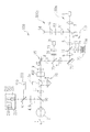
図3は、本実施形態の眼底撮影装置の光学系を示した模式図である。本実施形態の眼底撮影装置は、大別して、被検眼の眼底からの反射光に基づいて被検眼の眼底を撮像する眼底撮像光学系100と、被検眼の波面収差を検出するための波面センサ73を有し、被検眼眼底に測定光を投光し、その反射光を波面センサ73にて指標パターン像として受光する波面収差検出光学系(以下、収差検出光学系と記載する。)110と、被検眼の収差を補正するために眼底撮像光学系100に配置された収差補正ユニット10,72と、眼底撮像光学系100で得られる眼底画像(以下、第1眼底画像と記す)の撮影位置を指定するための眼底の観察画像(以下、第2眼底画像と記す)を得るための第2撮影ユニット200、撮影される被検眼Eの固視微動等による位置ずれの経時変化を検出し、移動位置情報を得るトラッキング用ユニット(位置検出部)300、を備える。ここで、眼底撮像光学系100は、被検眼Eの眼底を高解像度(高分解能)・高倍率で撮影する。また、収差補正ユニットは、被検眼の低次収差(視度:例えば、球面度数)を補正するための視度補正部10と、被検眼の高次収差を補正するための高次収差補正部(波面補償デバイス)72と、に大別される。   FIG. 3 is a schematic diagram showing an optical system of the fundus imaging apparatus of the present embodiment. The fundus imaging apparatus of the present embodiment is broadly divided into a fundus imaging optical system 100 that images the fundus of the subject's eye based on the reflected light from the fundus of the subject's eye, and a wavefront sensor 73 for detecting the wavefront aberration of the subject's eye. A wavefront aberration detection optical system (hereinafter referred to as an aberration detection optical system) 110 that projects measurement light onto the fundus of the eye to be examined and receives the reflected light as an index pattern image by the wavefront sensor 73; Aberration correction units 10 and 72 arranged in the fundus imaging optical system 100 to correct the aberration of the eye to be examined, and a photographing position of a fundus image obtained by the fundus imaging optical system 100 (hereinafter referred to as a first fundus image) are shown. A second imaging unit 200 for obtaining an observation image of the fundus for designating (hereinafter referred to as a second fundus image), detecting a time-dependent change in position shift due to fixation eye movement of the eye E to be imaged, and moving To obtain location information Kkingu for unit (position detection unit) 300 comprises a. Here, the fundus imaging optical system 100 captures the fundus of the eye E with high resolution (high resolution) and high magnification. The aberration correction unit includes a diopter correction unit 10 for correcting low-order aberrations (diopter: for example, spherical power) of the eye to be examined, and a high-order aberration correction unit for correcting high-order aberrations of the eye to be examined. (Wavefront compensation device) 72.

眼底撮像光学系100は、被検眼Eに照明光(照明光束)を照射し眼底を2次元的に照明する第1照明光学系100aと、眼底に照射された照明光の反射光(反射光束)を受光して第1眼底画像を得るための第1撮影光学系100bと、収差補正部72と、を備える。眼底撮像光学系100は、例えば、共焦点光学系を用いた走査型レーザ検眼鏡の構成とされる。   The fundus imaging optical system 100 includes a first illumination optical system 100a that irradiates the eye E with illumination light (illumination light beam) to illuminate the fundus two-dimensionally, and reflected light (reflected light beam) of the illumination light irradiated on the fundus. And a first correction optical system 100b for obtaining a first fundus image and an aberration correction unit 72. The fundus imaging optical system 100 has, for example, a scanning laser ophthalmoscope configuration using a confocal optical system.

第1照明光学系100aは、眼底を照明するための照明光を出射する光源1(第1光源),照明光(スポット光)を眼底上で2次元的に走査する走査部15を有する。光源1は、被検眼に視認されにくい近赤外域の照明光を出射する。本実施形態では光源1は、波長840nmのSLD(Super Luminescent Diode)光源が用いられる。なお、光源としては、収束性の高い特性を持つスポット光を出射するものであればよく、例えば、半導体レーザ等であってもよい。   The first illumination optical system 100a includes a light source 1 (first light source) that emits illumination light for illuminating the fundus and a scanning unit 15 that two-dimensionally scans the illumination light (spot light) on the fundus. The light source 1 emits near-infrared illumination light that is hardly visible to the eye to be examined. In the present embodiment, the light source 1 is an SLD (Super Luminescent Diode) light source having a wavelength of 840 nm. The light source may be any light source that emits spot light having a high convergence property, and may be, for example, a semiconductor laser.

はじめに、第1照明光学系100aを説明する。光源1から眼底に到るまでの光路には、レンズ2、ビームスプリッタ3、偏光板4、レンズ5、ビームスプリッタ71、レンズ6、波面補償デバイス72、レンズ7、ビームスプリッタ75が配置される。そしてさらに、レンズ8、走査部15、レンズ9、2次元状に走査される照明光の走査位置を補正するための偏向部400、2枚のプリズムからなる視度補正部10、レンズ11、第2撮影ユニット200等の光路を第1照明光学系と略同軸にするビームスプリッタ90が配置される。なお、ビームスプリッタ3は、本実施形態では、ハーフミラーとされている。   First, the first illumination optical system 100a will be described. In the optical path from the light source 1 to the fundus, a lens 2, a beam splitter 3, a polarizing plate 4, a lens 5, a beam splitter 71, a lens 6, a wavefront compensation device 72, a lens 7, and a beam splitter 75 are arranged. Further, the lens 8, the scanning unit 15, the lens 9, the deflection unit 400 for correcting the scanning position of the illumination light scanned two-dimensionally, the diopter correction unit 10 composed of two prisms, the lens 11, 2 A beam splitter 90 is disposed so that the optical path of the photographing unit 200 or the like is substantially coaxial with the first illumination optical system. The beam splitter 3 is a half mirror in this embodiment.

光源1から出射された照明光は、レンズ2により平行光とされた後、ビームスプリッタ3を介し、本実施形態では偏光板4によりS偏光成分のみの光束とされる。偏光板4を経た照明光は、レンズ5により一旦集光し、ビームスプリッタ71を介してレンズ6により平行光束とされ、波面補償デバイス72に入射する。波面補償デバイス72にて反射した照明光は、レンズ7、レンズ8によりリレーされ、走査部15に向かう。   Illumination light emitted from the light source 1 is converted into parallel light by the lens 2 and then converted into a light beam of only the S-polarized component by the polarizing plate 4 in this embodiment via the beam splitter 3. The illumination light that has passed through the polarizing plate 4 is once condensed by the lens 5, converted into a parallel light beam by the lens 6 through the beam splitter 71, and enters the wavefront compensation device 72. The illumination light reflected by the wavefront compensation device 72 is relayed by the lens 7 and the lens 8 and travels toward the scanning unit 15.

走査部15は、照明光を眼底上で2次元的に走査する構成とされ、ここでは、図示するように、眼底でXY方向に照明光を走査する。本実施形態では、照明光を眼底にて水平方向(X方向)に偏向させ走査するための偏向部材となるレゾナントミラーと、水平方向の走査方向に対して垂直方向(Y方向)に偏向させ走査するための偏向部材となるガルバノミラーと、各ミラーを駆動する駆動部を備える。走査部15を経た照明光は、レンズ9にて再び集光される。偏向部400は、走査部15を経た照明光を水平方向及び垂直方向に対して所定量だけさらに偏向させる役目を持ち、本実施形態では2枚のガルバノミラーにより構成されている。偏向部400を経た照明光は、視度補正部10、レンズ11、ビームスプリッタ90を経て被検眼Eの眼底に集光し、走査部15によって眼底上を2次元的に走査することとなる。なお、視度補正部10は、駆動部10aを有し、一方のプリズムが図示する矢印方向に移動することにより、光路長を変えることができ、視度補正の役目を果たしている。なお、視度補正部10は、駆動部と、駆動部の駆動によって光軸方向に移動可能なレンズからなる構成であってもよい。また、ビームスプリッタ90は、本実施形態ではダイクロイックミラーであり、後述する第2撮影ユニット200、及びトラッキング用ユニット300からの光束を反射させ、光源1及び後述する光源76からの光束を透過させる特性を持つ。なお、光源1及び光源76の出射端と被検眼Eとは共役とされている。このようにして、照明光を眼底に2次元的に照射する第1照明光学系が形成される。   The scanning unit 15 is configured to scan illumination light two-dimensionally on the fundus, and here, as illustrated, scans illumination light in the XY direction on the fundus. In the present embodiment, a resonant mirror serving as a deflecting member for deflecting and scanning illumination light in the horizontal direction (X direction) on the fundus, and scanning by deflecting the illumination light in a direction perpendicular to the horizontal scanning direction (Y direction). A galvanometer mirror serving as a deflection member and a drive unit for driving each mirror. The illumination light that has passed through the scanning unit 15 is condensed again by the lens 9. The deflecting unit 400 has a function of further deflecting the illumination light having passed through the scanning unit 15 by a predetermined amount with respect to the horizontal direction and the vertical direction, and is configured by two galvanometer mirrors in the present embodiment. The illumination light that has passed through the deflection unit 400 is condensed on the fundus of the eye E through the diopter correction unit 10, the lens 11, and the beam splitter 90, and is scanned two-dimensionally on the fundus by the scanning unit 15. The diopter correction unit 10 includes a drive unit 10a, and one prism moves in the direction of the arrow shown in the figure, so that the optical path length can be changed and plays a role in diopter correction. The diopter correction unit 10 may be configured by a driving unit and a lens that can move in the optical axis direction by driving the driving unit. In addition, the beam splitter 90 is a dichroic mirror in the present embodiment, and reflects the light beam from the second imaging unit 200 and tracking unit 300 described later, and transmits the light beam from the light source 1 and the light source 76 described later. have. Note that the emission ends of the light source 1 and the light source 76 and the eye E to be examined are conjugate. In this way, the first illumination optical system that irradiates the fundus with illumination light two-dimensionally is formed.

次に、第1撮影光学系100bを説明する。第1撮影光学系100は、第1照明光学系100aにて説明したビームスプリッタ90からビームスプリッタ3までの光路を共通とし、さらにレンズ51、眼底と共役な位置に置かれるピンホール板52、集光レンズ53、受光素子54を含む。なお、本実施形態では、受光素子54はAPD(アバランシェフォトダイオード)が用いられている。   Next, the first photographing optical system 100b will be described. The first photographing optical system 100 has a common optical path from the beam splitter 90 to the beam splitter 3 described in the first illumination optical system 100a, and further includes a lens 51, a pinhole plate 52 placed at a position conjugate with the fundus, and a light collecting unit. An optical lens 53 and a light receiving element 54 are included. In this embodiment, the light receiving element 54 is an APD (avalanche photodiode).

光源1から出射された照明光における眼底からの反射光は、前述した第1照明光学系100aを逆に辿り、偏光板4にてS偏光の光だけ透過された後、ビームスプリッタ3により一部の光束が反射される。この反射光は、レンズ51を介してピンホール板52のピンホールに焦点を結ぶ。ピンホールにて焦点を結んだ反射光は、レンズ53を経て受光素子54に受光される。なお、照明光の一部は角膜上で反射されるが、ピンホール板52により大部分が除去され、角膜反射の画像への悪影響が低減される。このため、受光素子54は、角膜反射の影響を抑えて、眼底からの反射光を受光できる。なお、ビームスプリッタ3は、ホールミラーとされてもよい。この場合、ホールミラーのホールは、角膜反射光を第1撮影光学系100に入射することを抑制する。   The reflected light from the fundus of the illumination light emitted from the light source 1 traces the first illumination optical system 100a in the reverse direction and is transmitted by the polarizing plate 4 only for S-polarized light, and then partially reflected by the beam splitter 3. Is reflected. This reflected light is focused on the pinhole of the pinhole plate 52 through the lens 51. The reflected light focused at the pinhole is received by the light receiving element 54 through the lens 53. Although a part of the illumination light is reflected on the cornea, most of the illumination light is removed by the pinhole plate 52, and the adverse effect of the corneal reflection on the image is reduced. For this reason, the light receiving element 54 can receive reflected light from the fundus while suppressing the influence of corneal reflection. The beam splitter 3 may be a hall mirror. In this case, the hole of the Hall mirror suppresses the incident corneal reflection light from entering the first imaging optical system 100.

このようにして、第1撮影光学系100bが形成される。第1撮影光学系100bで受光された処理された画像が第1眼底画像となる。なお、第1撮影ユニット100で取得する眼底画像(眼底像)の画角が所定の角度となるように走査部15におけるミラーの振れ角(揺動角度)を定める。ここでは、眼底の所定の範囲を高倍率で観察、撮影する(ここでは、細胞レベルでの観察等をする)ために、画角を1度〜5度程度とする。本実施形態では、1.5度とする。被検眼の視度等にもよるが、第1眼底画像の撮影範囲は、500μm角程度とされる。   In this way, the first photographing optical system 100b is formed. The processed image received by the first imaging optical system 100b becomes the first fundus image. Note that the mirror swing angle (swing angle) in the scanning unit 15 is determined so that the angle of view of the fundus image (fundus image) acquired by the first photographing unit 100 is a predetermined angle. Here, in order to observe and photograph a predetermined range of the fundus at a high magnification (here, observation at a cell level or the like), the angle of view is set to about 1 to 5 degrees. In this embodiment, the angle is 1.5 degrees. Although depending on the diopter of the eye to be examined, the imaging range of the first fundus image is about 500 μm square.

次に、第2撮影ユニット200を説明する。第2撮影ユニットは、第1撮影ユニットの画角よりも広画角の眼底画像(第2眼底画像)を取得するためのユニットであり、取得される第2眼底画像は、前述した狭画角の第1眼底画像を得るための位置指定、及び位置確認用の画像として用いられる。このような第2眼底画像を取得するための第2撮影ユニット200は、被検眼Eの眼底画像を観察用として広画角(例えば20度〜60度程度)でリアルタイムに取得できればよい。したがって第2撮影ユニット200は、既存の眼底カメラの観察・撮影光学系や走査型レーザー検眼鏡(Scanning Laser Ophthalmoscope:SLO)の光学系、及び制御系を用いることができる。   Next, the second photographing unit 200 will be described. The second imaging unit is a unit for acquiring a fundus image (second fundus image) having a wider angle of view than the angle of view of the first imaging unit, and the acquired second fundus image has the narrow angle of view described above. Used for position designation and position confirmation for obtaining the first fundus image. The second imaging unit 200 for acquiring such a second fundus image only needs to be able to acquire the fundus image of the eye E to be examined in real time with a wide angle of view (for example, about 20 to 60 degrees). Therefore, the second imaging unit 200 can use an observation / imaging optical system of an existing fundus camera, an optical system of a scanning laser ophthalmoscope (SLO), and a control system.

次に、収差検出光学系110について説明する。前述のように、収差検出光学系110は、一部の光学素子を第1照明光学系100aの光路上に持ち、第1照明光学系100aと光路を一部共用している。収差検出光学系110は、波面センサ73、偏光板74、光源76、レンズ77、偏光板78、レンズ79、を含み、第1照明光学系の光路上に置かれるビームスプリッタ71からビームスプリッタ90までの光学部材を共用することにより構成されている。なお、波面センサ73は、例えば、多数のマイクロレンズからなるマイクロレンズアレイと、マイクロレンズアレイを透過した光束を受光させるための二次元撮像素子73a(2次元受光素子)からなる。また、収差検出用光源(第3光源)である光源76は、光源1と異なる赤外域の光を発する光源とされる。本実施形態では光源76は波長780nmのレーザ光を出射するレーザダイオードを用いている。光源76から出射したレーザ光は、レンズ77により平行光束とされ、偏光板78により光源1からの照明光と直交する偏光方向(P偏光)とされ、ビームスプリッタ75により第1照明光学系の光路に導かれる。なお、レンズ7、8の間に眼底共役位置があり、光源76の出射端はこの眼底共役位置と共役な関係とされる。なお、ビームスプリッタ75は、本実施形態ではハーフミラーとされている。偏光板78は、眼底へと照射される第3光源の光を所定の偏光方向とする役割を持ち、波面補償部が備える第1偏光手段の役割を持つ。   Next, the aberration detection optical system 110 will be described. As described above, the aberration detection optical system 110 has some optical elements on the optical path of the first illumination optical system 100a, and shares a part of the optical path with the first illumination optical system 100a. The aberration detection optical system 110 includes a wavefront sensor 73, a polarizing plate 74, a light source 76, a lens 77, a polarizing plate 78, and a lens 79. From the beam splitter 71 to the beam splitter 90 placed on the optical path of the first illumination optical system. These optical members are shared. The wavefront sensor 73 includes, for example, a microlens array composed of a number of microlenses and a two-dimensional imaging element 73a (two-dimensional light receiving element) for receiving a light beam that has passed through the microlens array. A light source 76 that is an aberration detection light source (third light source) is a light source that emits light in an infrared region different from that of the light source 1. In the present embodiment, the light source 76 uses a laser diode that emits laser light having a wavelength of 780 nm. The laser light emitted from the light source 76 is converted into a parallel light beam by the lens 77, and the polarization direction (P-polarized light) is orthogonal to the illumination light from the light source 1 by the polarizing plate 78, and the optical path of the first illumination optical system by the beam splitter 75. Led to. Note that there is a fundus conjugate position between the lenses 7 and 8, and the emission end of the light source 76 has a conjugate relationship with this fundus conjugate position. The beam splitter 75 is a half mirror in this embodiment. The polarizing plate 78 has a role of making the light of the third light source irradiated to the fundus a predetermined polarization direction, and has a role of a first polarizing means provided in the wavefront compensation unit.

ビームスプリッタ75により反射したレーザ光は、第1照明光学系100aの光路を経て被検眼Eの眼底に集光される。眼底で反射されたレーザ光は、第1照明光学系100aの各光学部材を経て波面補償デバイス72にて反射し、ビームスプリッタ71により第1照明光学系100aの光路から外れ、レンズ79、S偏光成分のみを通す偏光板74を経て波面センサ73へと導かれる。偏光板74は、波面補償部に備えられた第2偏光手段であり、眼底へと照射される第3光源の光が持つ偏光方向(P偏光光)を遮断し、この偏光方向に直交する偏光方向(S偏光光)を透過し、波面センサ73へと導光する役割を持つ。なお、ビームスプリッタ71は、光源1の波長の光(840nm)を透過し、収差検出用の光源76の波長の光(780nm)を反射する特性とされる。従って、波面センサ73では、照射したレーザ光の眼底での散乱光のうちS偏光成分を持つ光が検出される。このようにして、角膜や光学素子で反射される光が波面センサ73に検出されることを抑制している。また、走査部15、波面補償デバイス72の反射面、及び波面センサ73のマイクロレンズアレイは、被検眼の瞳と略共役とされる。また、波面センサ73の受光面は被検眼Eの眼底と略共役とされる。波面センサ73には、低次収差及び高次収差を含む波面収差が検出できる素子、例えば、ハルトマンシャック検出器や光強度の変化を検出する波面曲率センサ等を用いる。   The laser beam reflected by the beam splitter 75 is condensed on the fundus of the eye E through the optical path of the first illumination optical system 100a. The laser beam reflected from the fundus is reflected by the wavefront compensation device 72 through each optical member of the first illumination optical system 100a, deviated from the optical path of the first illumination optical system 100a by the beam splitter 71, the lens 79, and S-polarized light. The light is guided to the wavefront sensor 73 through the polarizing plate 74 through which only the component passes. The polarizing plate 74 is a second polarization unit provided in the wavefront compensation unit, and blocks the polarization direction (P-polarized light) of the light of the third light source irradiated to the fundus and is polarized perpendicular to the polarization direction. It plays the role of transmitting the direction (S-polarized light) and guiding it to the wavefront sensor 73. Note that the beam splitter 71 transmits light (840 nm) having the wavelength of the light source 1 and reflects light (780 nm) having the wavelength of the light source 76 for detecting aberration. Accordingly, the wavefront sensor 73 detects light having an S-polarized component from the scattered light on the fundus of the irradiated laser light. In this way, light reflected by the cornea and the optical element is suppressed from being detected by the wavefront sensor 73. The scanning unit 15, the reflection surface of the wavefront compensation device 72, and the microlens array of the wavefront sensor 73 are substantially conjugate with the pupil of the eye to be examined. The light receiving surface of the wavefront sensor 73 is substantially conjugate with the fundus of the eye E. As the wavefront sensor 73, an element capable of detecting wavefront aberration including low-order aberration and high-order aberration, for example, a Hartmann Shack detector, a wavefront curvature sensor that detects a change in light intensity, or the like is used.

また、波面補償デバイス72は、例えば、液晶空間光変調器とし、反射型のLCOS(Liquid Crystal On Silicon)等を用いるものとしている。そして、波面補償デバイス72は、眼底撮像光学系100の光路中に配置され、入射光の波面を制御して被検眼の波面収差を補償する。なお、波面補償デバイス72は、光源1からの照明光(S偏光光)、照明光の眼底での反射光(S偏光光)、波面収差検出用光の反射光(S偏光成分)等の所定の直線偏光(S偏光)に対して収差を補償することが可能な向きに配置される。これにより、波面補償デバイス72は、入射する光のS偏光成分を変調できる。また、波面補償デバイス72は、その液晶層内の液晶分子の配列方向が入射する反射光の偏光面と略平行であり、さらに、液晶分子が液晶層への印加電圧の変化に応じて回転する所定の面が、波面補償デバイス72に対する眼底からの反射光の入射光軸及び反射光軸と、波面補償デバイス72が持つミラー層の法線と、を含む平面に対して略平行になるように、配置されている。   The wavefront compensation device 72 is, for example, a liquid crystal spatial light modulator and uses a reflective LCOS (Liquid Crystal On Silicon) or the like. The wavefront compensation device 72 is disposed in the optical path of the fundus imaging optical system 100 and controls the wavefront of incident light to compensate for the wavefront aberration of the eye to be examined. The wavefront compensation device 72 is a predetermined unit such as illumination light from the light source 1 (S-polarized light), reflected light from the fundus of the illumination light (S-polarized light), reflected light from wavefront aberration detection light (S-polarized light component), or the like. Are arranged in a direction capable of compensating the aberration with respect to the linearly polarized light (S-polarized light). As a result, the wavefront compensation device 72 can modulate the S-polarized component of the incident light. Further, the wavefront compensation device 72 has a liquid crystal molecule arrangement direction in the liquid crystal layer substantially parallel to the polarization plane of the incident reflected light, and the liquid crystal molecules rotate in accordance with a change in voltage applied to the liquid crystal layer. The predetermined surface is substantially parallel to a plane including the incident optical axis and the reflected optical axis of the reflected light from the fundus to the wavefront compensation device 72, and the normal of the mirror layer of the wavefront compensation device 72. Have been placed.

なお、本実施例においては、波面補償デバイス72は、液晶変調素子とし、反射型のLCOS(Liquid Crystal On Silicon)等を用いるものとしているが、これに限るものではない。反射型の波面補償デバイスであればよい。例えば、MEMS(Micro Electro Mechanical Systems)の一形態であるデフォーマブルミラーを用いてもよい。また、反射型の波面補償デバイスではなく、眼底からの反射光を透過させて波面収差を補償するような透過型の波面補償デバイスを用いることもできる。   In this embodiment, the wavefront compensation device 72 is a liquid crystal modulation element and uses a reflective LCOS (Liquid Crystal On Silicon) or the like, but is not limited thereto. Any reflective wavefront compensation device may be used. For example, a deformable mirror that is a form of MEMS (Micro Electro Mechanical Systems) may be used. Further, instead of a reflection type wavefront compensation device, a transmission type wavefront compensation device that transmits reflected light from the fundus and compensates for wavefront aberration can also be used.

なお、以上の説明では、収差検出用光源として、第1光源とは異なる波長の照明光を出射する光源を用いたが、第1光源を収差検出用光源として用いてもよい。   In the above description, a light source that emits illumination light having a wavelength different from that of the first light source is used as the aberration detection light source. However, the first light source may be used as the aberration detection light source.

なお、以上説明した本実施形態では、波面センサ及び波面補償デバイスを被検眼の瞳共役としたが、被検眼の前眼部の所定部位と略共役な位置であればよく、例えば、角膜共役であってもよい。   In the present embodiment described above, the wavefront sensor and the wavefront compensation device are the pupil conjugate of the eye to be examined. However, the position may be a position that is substantially conjugate with a predetermined part of the anterior eye portion of the eye to be examined. There may be.

次に、眼底撮影装置の制御系を説明する。図4は、本実施形態の眼底撮影装置の制御系を示したブロック図である。装置全体の制御を行う制御部80には、光源1、走査部15、受光素子51、波面補償デバイス72、波面センサ73、光源76、第2撮影ユニット200、受光素子251、トラッキング用ユニット300、偏向部400、偏向部410、視度補正部10、Y駆動部35、X駆動部38、Z軸移動機構39の駆動部、が接続される。また、記憶部81、コントロール部82、画像処理部83、モニタ85、が接続される。画像処理部83は受光素子51、第2撮影ユニット200にて受光した信号に基づきモニタ85に画角の異なる被検眼眼底の画像、つまり、第1眼底画像及び第2眼底画像を形成する。記憶部81には種々の設定情報や撮影画像が保存される。なお、モニタ85には、例えば、外部のパ−ソナルコンピューターのモニタや装置に備えられているモニタが考えられる。モニタ85には、所定のフレームレートにて更新される眼底画像(第1眼底画像、及び第2眼底画像)が表示される。フレームレートとしては、例えば、10〜100Hzとされる。このようにして、動画として眼底画像が表示される。本実施形態では、制御部80は、モニタ85の表示制御部80、偏向部400、410の駆動制御部80、光源1、76等の出射制御部80の機能を兼ねる。   Next, a control system of the fundus imaging apparatus will be described. FIG. 4 is a block diagram showing a control system of the fundus imaging apparatus of the present embodiment. The control unit 80 that controls the entire apparatus includes a light source 1, a scanning unit 15, a light receiving element 51, a wavefront compensation device 72, a wavefront sensor 73, a light source 76, a second imaging unit 200, a light receiving element 251, a tracking unit 300, The deflection unit 400, the deflection unit 410, the diopter correction unit 10, the Y drive unit 35, the X drive unit 38, and the drive unit of the Z-axis moving mechanism 39 are connected. A storage unit 81, a control unit 82, an image processing unit 83, and a monitor 85 are connected. The image processing unit 83 forms, on the monitor 85, images of the fundus oculi having different angles of view, that is, a first fundus image and a second fundus image, based on signals received by the light receiving element 51 and the second imaging unit 200. Various setting information and captured images are stored in the storage unit 81. As the monitor 85, for example, a monitor of an external personal computer or a monitor provided in an apparatus can be considered. The fundus images (first fundus image and second fundus image) updated at a predetermined frame rate are displayed on the monitor 85. The frame rate is, for example, 10 to 100 Hz. In this way, the fundus image is displayed as a moving image. In the present embodiment, the control unit 80 also functions as the display control unit 80 of the monitor 85, the drive control unit 80 of the deflection units 400 and 410, and the emission control unit 80 such as the light sources 1 and 76.

なお、波面補償デバイス72を制御する場合、波面センサ73で検出された波面収差に基づいて、波面補償デバイス72が制御され、光源76の反射光のS偏光成分と共に、光源1から出射される照明光とその反射光の高次収差が取り除かれる。このようにして、光源1から出射された照明光とその反射光が持つ収差が取り除かれる。言い換えると、被検眼Eの高次収差が取り除かれた(波面補償された)高解像度の第1眼底画像が得られることとなる。この場合、視度補正部10によって低次収差が補正される。   When the wavefront compensation device 72 is controlled, the wavefront compensation device 72 is controlled based on the wavefront aberration detected by the wavefront sensor 73, and the illumination emitted from the light source 1 together with the S-polarized component of the reflected light of the light source 76. Higher order aberrations of the light and its reflected light are removed. In this way, the aberration of the illumination light emitted from the light source 1 and the reflected light is removed. In other words, a high-resolution first fundus image from which the high-order aberration of the eye E is removed (wavefront compensated) is obtained. In this case, the low-order aberration is corrected by the diopter correction unit 10.

また、検者が顎台22を電動駆動でXYZの三次元方向へ移動させる時に使用するX方向顎台操作スイッチ47a、Y方向顎台操作スイッチ47b、Z方向顎台操作スイッチ47cがそれぞれ設けられている。   In addition, an X-direction chin rest operation switch 47a, a Y-direction chin rest operation switch 47b, and a Z-direction chin rest operation switch 47c that are used when the examiner moves the chin rest 22 in the three-dimensional directions of XYZ by electric drive are provided. ing.

以上のような構成の眼底撮影装置において、その動作を図5に示すフローチャートを用いて説明する。   The operation of the fundus imaging apparatus having the above configuration will be described with reference to the flowchart shown in FIG.

検者により、初めに、モニタ85の画面上に表示された図示無き前眼部画像を観察しながら、各顎台操作スイッチ47a〜47cを操作し、顎台22の位置調整を行い、粗くアライメントを行う。また、検者は、被検者が図示無き固視標を固視するように指示する。   First, the examiner operates the chin rest operation switches 47a to 47c while observing the anterior eye part image (not shown) displayed on the screen of the monitor 85, adjusts the position of the chin rest 22, and performs rough alignment. I do. Further, the examiner instructs the subject to fixate a fixation target (not shown).

顎台22による粗いアライメントが完了し、検者により図示無き測定スイッチが選択されると、制御部80により、視度補正部10を用いて視度補正が行われ、次いで、収差補正に必要な波面検出を行う。   When rough alignment by the chin rest 22 is completed and a measurement switch (not shown) is selected by the examiner, diopter correction is performed by the control unit 80 using the diopter correction unit 10, and then necessary for aberration correction. Perform wavefront detection.

図6は、波面センサ上の指標パターン像と補償可能領域の具体例について説明する図である。図7はモニタ85の画面上に表示された収差補正画面40を示した図である。収差補正画面40には、波面センサ73の二次元撮像素子73aに受光された指標パターン像(本実施例においては、ハルトマン像とし、以下、ハルトマン像と記載する)と、収差補正の補正度合をグラフィック表示した収差補正グラフィック41と、実際に撮影されている眼底の細胞像画像42と、が表示されている。   FIG. 6 is a diagram for explaining a specific example of the index pattern image on the wavefront sensor and the compensable region. FIG. 7 is a diagram showing the aberration correction screen 40 displayed on the screen of the monitor 85. On the aberration correction screen 40, the index pattern image received by the two-dimensional imaging device 73a of the wavefront sensor 73 (in this embodiment, a Hartmann image, hereinafter referred to as a Hartmann image) and the correction degree of the aberration correction are displayed. An aberration correction graphic 41 displayed graphically and a cell image image 42 of the fundus that is actually photographed are displayed.

ハルトマン像(ドットパターン像)31は、波面センサ73上に受光された複数の点像31aの集まりを示す。レンズアレイを通過した眼底反射光は、波面センサ73の二次元撮像素子73aに受光され、ハルトマン像として撮像される。そして、ハルトマン像31は、モニタ85上に表示される。なお、波面センサ73によって点像31aが検出された領域では、収差検出が可能である。   A Hartmann image (dot pattern image) 31 represents a group of a plurality of point images 31 a received on the wavefront sensor 73. The fundus reflection light that has passed through the lens array is received by the two-dimensional imaging device 73a of the wavefront sensor 73 and captured as a Hartmann image. The Hartmann image 31 is displayed on the monitor 85. In the region where the point image 31a is detected by the wavefront sensor 73, aberration detection is possible.

円32は、二次元撮像素子73a上において、波面補償デバイス72によって収差補正可能な領域を仮想的に示したものである。そして、円32に対応するグラフィックが、モニタ85上のハルトマン像に重合されて表示される。円32の中心に位置するマークは、波面センサ73上における補償可能領域の中心位置を示すグラフィックである。   A circle 32 virtually indicates an area in which aberration correction can be performed by the wavefront compensation device 72 on the two-dimensional image sensor 73a. The graphic corresponding to the circle 32 is superimposed on the Hartmann image on the monitor 85 and displayed. The mark located at the center of the circle 32 is a graphic indicating the center position of the compensable region on the wavefront sensor 73.

そして、円32の外周、領域、波面センサ73上におけるその位置情報が予め記憶部81に設定されている。これらは、キャリブレーション又はシミュレーションなどにより予め求めておけばよい。なお、波面補償デバイス72において、補償可能領域は、入射光全体の内、ある一部の領域(例えば、瞳孔上における直径4mm領域)の光束に制限される。このため、他の入射光については、受光素子54に向けて反射されるが、波面は補償されない。   Then, the outer circumference, area, and position information of the circle 32 on the wavefront sensor 73 are set in the storage unit 81 in advance. These may be obtained in advance by calibration or simulation. In the wavefront compensation device 72, the compensable region is limited to a light beam in a certain region (for example, a 4 mm diameter region on the pupil) of the entire incident light. For this reason, other incident light is reflected toward the light receiving element 54, but the wavefront is not compensated.

ここで、収差補正は、波面センサ73による収差検出結果に基づいて行われる。すなわち、円32の領域内においてハルトマン像31が形成された領域では、波面の状態が検出可能である(図6(b)参照)。一方、円32の領域内において、ハルトマン像31が形成されていない領域Sにおいては、波面の状態が検出されない。ここで、波面データの一部が欠損している場合、波面全体の情報が得られないため、波面補正領域における波面収差が適正に測定されない(図6(a)参照)。よって、図7(a)に示すように、収差補正が実行されても、収差補正グラフィック41に示されるように適正に収差が除去されない。また、細胞像画像42に示されるように撮影が困難となる。   Here, the aberration correction is performed based on the aberration detection result by the wavefront sensor 73. That is, in the region where the Hartmann image 31 is formed in the region of the circle 32, the wavefront state can be detected (see FIG. 6B). On the other hand, in the region of the circle 32, in the region S where the Hartmann image 31 is not formed, the wavefront state is not detected. Here, when a part of the wavefront data is missing, information on the entire wavefront cannot be obtained, so that the wavefront aberration in the wavefront correction region is not properly measured (see FIG. 6A). Therefore, as shown in FIG. 7A, even when the aberration correction is performed, the aberration is not properly removed as shown in the aberration correction graphic 41. In addition, as shown in the cell image 42, photographing becomes difficult.

以下に、円32の領域内をハルトマン像31で満たすための処置方法について説明する。制御部80は、波面センサ73上に設定された波面補償デバイス72の補償可能領域(例えば、円32)と波面センサ73による指標パターン像(例えば、ハルトマン像31)の受光領域とのずれ情報を検出する。そして、制御部80は、検出結果に基づいてY軸移動機構34/X軸移動機構36を制御し、そのずれ情報が許容範囲内に収まるように顎台22を移動させる。   A treatment method for filling the area of the circle 32 with the Hartmann image 31 will be described below. The control unit 80 obtains deviation information between the compensation area (for example, the circle 32) of the wavefront compensation device 72 set on the wavefront sensor 73 and the light receiving area of the index pattern image (for example, the Hartmann image 31) by the wavefront sensor 73. To detect. Then, the control unit 80 controls the Y-axis moving mechanism 34 / X-axis moving mechanism 36 based on the detection result, and moves the jaw table 22 so that the deviation information is within the allowable range.

具体的に説明すると、初めに、制御部80は、波面センサ73で受光されたハルトマン像31の内で最も外側で受光された点像位置を順に検出していきハルトマン像外周31bの位置情報を検出する。これにより、ハルトマン像31の検出領域が求められる。   Specifically, first, the control unit 80 sequentially detects the position of the point image received at the outermost side among the Hartmann images 31 received by the wavefront sensor 73, and obtains positional information of the Hartmann image outer periphery 31b. To detect. Thereby, the detection area of the Hartmann image 31 is obtained.

次いで、制御部80は、ハルトマン像外周31bの位置情報と円32(収差補正可能領域)の位置情報を比較して、その比較結果に基づいて波面測定領域が収差補正可能領域を許容範囲以上満たしているかを判定する。これにより、眼Eの収差を補正できるか否かが判定される。   Next, the control unit 80 compares the position information of the Hartmann image outer periphery 31b with the position information of the circle 32 (aberration correctable region), and based on the comparison result, the wavefront measurement region satisfies the aberration correctable region beyond the allowable range. Judge whether it is. Thereby, it is determined whether or not the aberration of the eye E can be corrected.

より具体的には、制御部80は、ハルトマン像外周31bに囲まれた領域(点線参照)と円32に囲まれた領域を比較する。ここで、制御部80は、円32の成す領域がハルトマン像外周31bの成す領域内に収まっている場合には、十分である(OK)と判定する(図6(b)参照)。また、制御部80は、円32の成す領域が外周31bの成す領域内に収まっていない場合には、不十分である(NG)と判定する(図6(a)参照)。   More specifically, the control unit 80 compares the region surrounded by the Hartmann image outer periphery 31b (see the dotted line) with the region surrounded by the circle 32. Here, the control unit 80 determines that it is sufficient (OK) when the region formed by the circle 32 is within the region formed by the Hartmann image outer periphery 31b (see FIG. 6B). Moreover, the control part 80 determines with it being inadequate (NG), when the area | region which the circle | round | yen 32 comprises is not settled in the area | region which the outer periphery 31b comprises (refer Fig.6 (a)).

制御部80は、NGと判定すると、ハルトマン像31の外周31bの成す領域内に円32の成す領域が入るように、X駆動部35、Y駆動部38を駆動させ、顎台22をXY方向に移動させる。これにより、図6(b)に示されるように、ハルトマン像外周31a内に円32が収まり、収差補正可能な状態となる。また、図7(b)に示すように、収差補正グラフィック41に示されるように収差が除去された状態となり、細胞像画像42においても、収差が除去された画像が表示される。   If the control unit 80 determines that NG, the X drive unit 35 and the Y drive unit 38 are driven so that the region formed by the circle 32 enters the region formed by the outer periphery 31b of the Hartmann image 31, and the jaw table 22 is moved in the XY direction. Move to. As a result, as shown in FIG. 6B, the circle 32 is contained in the Hartmann image outer periphery 31a, and the aberration can be corrected. Further, as shown in FIG. 7B, the aberration is removed as shown in the aberration correction graphic 41, and an image from which the aberration is removed is also displayed in the cell image 42.

上記のように顎台22の位置が調整された後、制御部80は、波面センサ73の検出結果に基づいて眼Eの波面収差を検出し、その検出結果に基づいて波面補償デバイス72を制御する。以上のようにして波面収差が補償され、所定のトリガ信号が出力されると、眼底の細胞像が動画像又は静止画像として撮影される。   After the position of the chin rest 22 is adjusted as described above, the control unit 80 detects the wavefront aberration of the eye E based on the detection result of the wavefront sensor 73 and controls the wavefront compensation device 72 based on the detection result. To do. When wavefront aberration is compensated as described above and a predetermined trigger signal is output, a cell image of the fundus is captured as a moving image or a still image.

なお、撮影中において、眼Eの固視方向が大きく変化され、被検眼の位置がずれることで、ハルトマン像31の外周31a内から円32が外れる場合がある。そこで、制御部80は、再びハルトマン像31内に円32が収まるように顎台22を移動させる。すなわち、制御部80は、顎台22を用いたトラッキングを行う。   During imaging, the fixation direction of the eye E is greatly changed, and the position of the eye to be inspected is displaced, so that the circle 32 may come off from the outer periphery 31a of the Hartmann image 31. Therefore, the control unit 80 moves the jaw table 22 so that the circle 32 is again accommodated in the Hartmann image 31. That is, the control unit 80 performs tracking using the chin rest 22.

以上のような構成によれば、被検眼の固視方向の変化によって波面補償領域における眼Eの収差情報が取得できなくなっても、顎台22の移動によって測定位置のずれが補正されるので、眼底の微小領域がスムーズに撮影される。   According to the above configuration, even if the aberration information of the eye E in the wavefront compensation region cannot be acquired due to the change in the fixation direction of the eye to be examined, the shift of the measurement position is corrected by the movement of the jaw table 22, A small area of the fundus is photographed smoothly.

なお、上記判定において、制御部80は、ハルトマン像外周31bの全ての点像位置座標が円32の位置座標より外側又は同位置であり、且つ、ハルトマン像31外周の成す領域が円32外周の成す領域内に入っている場合には、OKと判定するようにしてもよい。また、制御部80は、ハルトマン像31外周の点像の位置座標が円32外周の位置座標より内側である場合には、NGと判定するようにしてもよい。   In the above determination, the control unit 80 determines that all point image position coordinates of the Hartmann image outer periphery 31b are outside or the same position as the position coordinates of the circle 32, and the area formed by the outer periphery of the Hartmann image 31 is the outer periphery of the circle 32. If it is within the area to be formed, it may be determined as OK. Further, the control unit 80 may determine that the position coordinates of the point image on the outer periphery of the Hartmann image 31 are inside the position coordinates on the outer periphery of the circle 32 as NG.

また、制御部80は、ハルトマン像31の中心座標を算出し、円32の中心座標と一致されるように顎台22を移動させても構わない。   The control unit 80 may calculate the center coordinates of the Hartmann image 31 and move the jaw table 22 so as to coincide with the center coordinates of the circle 32.

また、補償可能領域と波面センサによる指標パターン像の受光領域とのずれを検出する構成として、前眼部撮像光学系が用いられるようにしてもよい。例えば、前眼部撮像カメラ上に補償可能領域が設定され、前眼部像から画像処理により瞳孔部分が抽出され、補償可能領域の位置情報と瞳孔外周の位置情報とが比較されることにより各領域間のずれが検出されてもよい。   Further, an anterior ocular segment imaging optical system may be used as a configuration for detecting a shift between the compensable region and the light receiving region of the index pattern image by the wavefront sensor. For example, a compensable area is set on the anterior segment imaging camera, a pupil part is extracted from the anterior segment image by image processing, and the position information of the compensable area is compared with the position information of the outer periphery of the pupil, thereby A shift between regions may be detected.

なお、本実施例においては、顔支持ユニットを撮影部400に対して移動させる構成により、撮影部3の大型化・重量化によって撮影部3の移動が困難な場合であっても、眼Eに対する位置あわせができる。この場合、例えば、額あてや頬あてを移動させる駆動機構を設けてもよい。   In the present embodiment, the configuration in which the face support unit is moved with respect to the imaging unit 400 enables the eye E to be moved even when the imaging unit 3 is difficult to move due to the increase in size and weight of the imaging unit 3. Can be aligned. In this case, for example, a drive mechanism that moves the forehead and cheek pads may be provided.

なお、上記判定において、指標パターン像が補償可能領域を100%満たしていなくてもよく、一定の精度にて波面収差が測定されればよい(例えば、95%の領域)。そして、判定結果にてずれが検出された場合、制御部80は、X駆動部35、Y駆動部38を駆動させ、補償可能領域内におけるある許容範囲(例えば、一定の割合以上)を超えて指標パターン像が受光されるように顎台22を移動させる。   In the above determination, the index pattern image may not satisfy 100% of the compensable region, and the wavefront aberration may be measured with a certain accuracy (for example, 95% region). When a deviation is detected in the determination result, the control unit 80 drives the X drive unit 35 and the Y drive unit 38 to exceed a certain allowable range (for example, a certain ratio or more) within the compensation range. The jaw table 22 is moved so that the index pattern image is received.

なお、以上の説明において、検出光学系110と被検眼との位置関係が相対的に調整される構成であればよい。例えば、ずれ情報が許容範囲内に収まるように撮影部400を眼Eに対して移動する構成であってもよい。また、検出光学系110の光路中に、測定光束の進行方向を変更する光偏向部を設け、光偏向部の駆動により位置関係が調整されてもよい。   In the above description, any configuration may be used as long as the positional relationship between the detection optical system 110 and the eye to be examined is relatively adjusted. For example, the configuration may be such that the photographing unit 400 is moved with respect to the eye E so that the shift information is within an allowable range. In addition, a light deflection unit that changes the traveling direction of the measurement light beam may be provided in the optical path of the detection optical system 110, and the positional relationship may be adjusted by driving the light deflection unit.

また、以上の説明において、ずれ情報に基づいて位置関係が相対的に調整されればよい。例えば、制御部80は、モニタ40を制御し、波面センサ73による指標パターン像の受光結果(例えば、ハルトマン像31)と、波面センサ73上の波面補償領域を示すグラフィック(例えば、円32、又は円32の中心マーク)と、をモニタ40のある表示領域に表示し、ずれ情報として出力する(例えば、図7参照)。   In the above description, the positional relationship may be relatively adjusted based on the deviation information. For example, the control unit 80 controls the monitor 40 to receive the index pattern image received by the wavefront sensor 73 (for example, the Hartmann image 31) and the graphic indicating the wavefront compensation area on the wavefront sensor 73 (for example, the circle 32, or The center mark of the circle 32) is displayed in a display area of the monitor 40, and is output as deviation information (see, for example, FIG. 7).

このようにすれば、検者は、波面補償デバイス72による補償可能領域が波面センサ73上のどの位置に対応するか把握できる。そして、検者は、モニタ40に表示されたずれ情報を確認しながら、顎台操作スイッチ47を操作する。なお、円32のような外周を示すグラフィックにより、検者は、位置合わせをさらに容易に行える。   In this way, the examiner can grasp to which position on the wavefront sensor 73 the area that can be compensated by the wavefront compensation device 72 corresponds. Then, the examiner operates the chin rest operation switch 47 while confirming the deviation information displayed on the monitor 40. It should be noted that the examiner can perform alignment more easily by the graphic indicating the outer periphery such as the circle 32.

なお、以上の説明においては、眼底撮像光学系100として、被検眼眼底と略共役な位置に配置された共焦点開口を介して被検眼眼底で反射した光束を受光して被検眼眼底の共焦点正面画像を撮影する共焦点光学系(SLO光学系)を用いるものとしたが、これに限るものではない(例えば、特表2001−507258号公報参照)。   In the above description, the fundus imaging optical system 100 receives the light beam reflected from the fundus of the eye to be examined through the confocal aperture disposed at a position substantially conjugate to the fundus of the eye to be examined, and confocals the fundus of the eye to be examined. Although a confocal optical system (SLO optical system) that captures a front image is used, the present invention is not limited to this (see, for example, JP 2001-507258 A).

例えば、被検眼眼底で反射した光束を二次元撮像素子により受光して被検眼の眼底正面画像を撮影する眼底カメラ光学系であってもよい。また、被検眼眼底で反射した光束と参照光による干渉光を受光して被検眼の断層画像を撮影する光干渉光学系(OCT光学系)であってもよい。   For example, a fundus camera optical system that captures a frontal image of the fundus of the subject's eye by receiving a light beam reflected from the fundus of the subject's eye with a two-dimensional image sensor. Further, it may be an optical interference optical system (OCT optical system) that captures a tomographic image of the eye to be inspected by receiving the light beam reflected from the fundus of the eye to be examined and the interference light by the reference light.

本実施形態の眼底撮影装置の外観図である。It is an external view of the fundus imaging apparatus of the present embodiment. 本実施形態の顔支持ユニットの移動機構を示す図である。It is a figure which shows the moving mechanism of the face support unit of this embodiment. 本実施形態の眼底撮影装置の光学系を示した模式図である。It is the schematic diagram which showed the optical system of the fundus imaging apparatus of this embodiment. 本実施形態の眼底撮影装置の制御系を示したブロック図である。It is the block diagram which showed the control system of the fundus imaging apparatus of this embodiment. 本装置における動作を示すフローチャートである。It is a flowchart which shows the operation | movement in this apparatus. モニタの画面上に表示された収差補正画面を示す図である。It is a figure which shows the aberration correction screen displayed on the screen of a monitor. ハルトマン像外周内に収差補正可能領域が収まっており、収差補正可能な状態を示す図である。It is a figure which shows the state which the aberration correction possible area | region has settled in the outer periphery of a Hartmann image, and an aberration correction is possible.

10 視度補正部
15 走査部
20 顔支持ユニット
22 顎台
34 Y軸方向移動機構
36 X軸方向移動機構
39 Z軸方向移動機構
40 収差補正画面
47 顎台操作スイッチ
72 波面補償デバイス
73 波面センサ
76 光源
80 制御部
85 モニタ
100 眼底撮像光学系
200 第2撮影ユニット
300 トラッキング用ユニット
400、410 偏向部
500 前眼部撮像光学系
DESCRIPTION OF SYMBOLS 10 Diopter correction | amendment part 15 Scan part 20 Face support unit 22 Jaw stage 34 Y-axis direction movement mechanism 36 X-axis direction movement mechanism 39 Z-axis direction movement mechanism 40 Aberration correction screen 47 Jaw stage operation switch 72 Wavefront compensation device 73 Wavefront sensor 76 Light source 80 Control unit 85 Monitor 100 Fundus imaging optical system 200 Second imaging unit 300 Tracking unit 400, 410 Deflection unit 500 Anterior segment imaging optical system

Claims (2)

被検眼眼底からの反射光を受光して眼底像を撮像する眼底撮像光学系と、
前記眼底撮像光学系の光路中に配置され、入射光の波面を制御して被検眼の波面収差を補償する波面補償デバイスと、
被検眼眼底に向けて測定光を投光しその反射光を波面センサにより指標パターン像として受光する検出光学系と、
記波面補償デバイスの補償可能領域の外周と前記波面センサによる指標パターン像の受光領域の外周とのずれ情報に基づいて、前記ずれ情報が許容範囲内に収まるように前記検出光学系と被検眼との位置関係を相対的に調整する位置調整手段と、を備えることを特徴とする波面補償付眼底撮影装置。
A fundus imaging optical system that receives reflected light from the fundus of the subject's eye and captures a fundus image;
A wavefront compensation device that is disposed in the optical path of the fundus imaging optical system and that controls the wavefront of incident light to compensate the wavefront aberration of the eye to be examined;
A test Idemitsu Gakukei you received as target pattern image by the wavefront sensor light reflected light projecting basil measurement light toward the fundus,
Based on the displacement information of the outer periphery of the light receiving area of the target pattern image by the wavefront sensor and the outer circumference of the compensable region before Symbol wavefront compensation device, said detection optical system and the eye to be examined so that the shift information is within the allowable range And a position adjusting means for relatively adjusting the positional relationship with the fundus imaging apparatus with wavefront compensation.
被検眼眼底からの反射光を受光して眼底像を撮像する眼底撮像光学系と、
前記眼底撮像光学系の光路中に配置され、入射光の波面を制御して被検眼の波面収差を補償する波面補償デバイスと、
被検眼眼底に向けて測定光を投光しその反射光を波面センサにより指標パターン像として受光する検出光学系と、
記波面補償デバイスの補償可能領域と前記波面センサによる指標パターン像の受光領域とのずれ情報に基づいて、前記ずれ情報が許容範囲内に収まるように前記検出光学系と被検眼との位置関係を相対的に調整する位置調整手段と、
表示手段の画面上にて、前記眼底撮像光学系よって撮像される眼底像と共に、前記波面補償デバイスによる収差補正の補正度合を前記波面センサの検出結果に基づいて表示する表示制御部と、を備えていることを特徴とする波面補償付眼底撮影装置。
A fundus imaging optical system that receives reflected light from the fundus of the subject's eye and captures a fundus image;
A wavefront compensation device that is disposed in the optical path of the fundus imaging optical system and that controls the wavefront of incident light to compensate the wavefront aberration of the eye to be examined;
A test Idemitsu Gakukei you received as target pattern image by the wavefront sensor light reflected light projecting basil measurement light toward the fundus,
Based on the displacement information of the previous SL wavefront compensation device compensating region and the light-receiving area of the target pattern image by the wavefront sensor, the positional relationship between the detection optical system and the eye to be examined so that the shift information is within the allowable range Position adjusting means for relatively adjusting
A display control unit for displaying, on the screen of the display means, a fundus image captured by the fundus imaging optical system and a correction degree of aberration correction by the wavefront compensation device based on a detection result of the wavefront sensor. A fundus imaging apparatus with wavefront compensation.
JP2010124871A 2010-05-31 2010-05-31 Fundus imaging device with wavefront compensation Expired - Fee Related JP5545984B2 (en)

Priority Applications (1)

Application Number Priority Date Filing Date Title
JP2010124871A JP5545984B2 (en) 2010-05-31 2010-05-31 Fundus imaging device with wavefront compensation

Applications Claiming Priority (1)

Application Number Priority Date Filing Date Title
JP2010124871A JP5545984B2 (en) 2010-05-31 2010-05-31 Fundus imaging device with wavefront compensation

Publications (3)

Publication Number Publication Date
JP2011250845A JP2011250845A (en) 2011-12-15
JP2011250845A5 JP2011250845A5 (en) 2013-07-11
JP5545984B2 true JP5545984B2 (en) 2014-07-09

Family

ID=45415325

Family Applications (1)

Application Number Title Priority Date Filing Date
JP2010124871A Expired - Fee Related JP5545984B2 (en) 2010-05-31 2010-05-31 Fundus imaging device with wavefront compensation

Country Status (1)

Country Link
JP (1) JP5545984B2 (en)

Families Citing this family (6)

* Cited by examiner, † Cited by third party
Publication number Priority date Publication date Assignee Title
JP6292799B2 (en) * 2012-10-26 2018-03-14 キヤノン株式会社 Ophthalmic apparatus and control method thereof
JP6116227B2 (en) * 2012-12-14 2017-04-19 キヤノン株式会社 Aberration measuring apparatus and method
JP6108810B2 (en) * 2012-12-14 2017-04-05 キヤノン株式会社 Ophthalmic apparatus and control method thereof
JP6230262B2 (en) * 2012-12-28 2017-11-15 キヤノン株式会社 Image processing apparatus and image processing method
JP6572560B2 (en) * 2015-03-02 2019-09-11 株式会社ニデック Fundus imaging device with wavefront compensation
JP6556179B2 (en) * 2017-03-22 2019-08-07 キヤノン株式会社 Aberration measuring apparatus and method

Family Cites Families (6)

* Cited by examiner, † Cited by third party
Publication number Priority date Publication date Assignee Title
US5777719A (en) * 1996-12-23 1998-07-07 University Of Rochester Method and apparatus for improving vision and the resolution of retinal images
JP4510534B2 (en) * 2004-06-22 2010-07-28 株式会社トプコン Optical characteristic measuring device and fundus image observation device
JP4988305B2 (en) * 2006-10-31 2012-08-01 株式会社ニデック Ophthalmic measuring device
JP2008161406A (en) * 2006-12-28 2008-07-17 Topcon Corp Ophthalmologic apparatus
JP5207916B2 (en) * 2008-10-24 2013-06-12 株式会社トプコン Wavefront aberration measuring apparatus and method
JP5207917B2 (en) * 2008-10-24 2013-06-12 株式会社トプコン Wavefront aberration measuring apparatus and method

Also Published As

Publication number Publication date
JP2011250845A (en) 2011-12-15

Similar Documents

Publication Publication Date Title
JP5259484B2 (en) Fundus photographing device
US8801178B2 (en) Fundus photographing apparatus
JP5845608B2 (en) Ophthalmic imaging equipment
JP6220248B2 (en) Ophthalmic apparatus and control method
JP5038703B2 (en) Ophthalmic equipment
JP5879830B2 (en) Fundus imaging device with wavefront compensation
JP5654271B2 (en) Ophthalmic equipment
JP6442960B2 (en) Fundus imaging device with wavefront compensation
JP5545984B2 (en) Fundus imaging device with wavefront compensation
JP2013169332A (en) Optical image photographing apparatus
JP6108811B2 (en) Imaging device
JP2011104135A (en) Optical image capturing method and apparatus thereof
JP6422629B2 (en) Fundus photographing device
US8777410B2 (en) Fundus photographing apparatus with wavefront compensation
JP5727197B2 (en) Fundus imaging device with wavefront compensation
JP2013070941A (en) Ophthalmologic photographing apparatus
JP2011115301A (en) Fundus imaging apparatus
JP2016067764A (en) Fundus photographing apparatus with wavefront compensation
JP6102369B2 (en) Fundus photographing device
JP7129162B2 (en) fundus imaging device
JP2013154063A (en) Ophthalmography device
JP5915034B2 (en) Fundus imaging device with wavefront compensation
JP6839902B2 (en) Ophthalmic microscope
JP6436293B2 (en) Fundus imaging device with wavefront compensation
JP2019202062A (en) Eyeground imaging apparatus and control method therefor

Legal Events

Date Code Title Description
A521 Written amendment

Free format text: JAPANESE INTERMEDIATE CODE: A523

Effective date: 20130527

A621 Written request for application examination

Free format text: JAPANESE INTERMEDIATE CODE: A621

Effective date: 20130527

A131 Notification of reasons for refusal

Free format text: JAPANESE INTERMEDIATE CODE: A131

Effective date: 20131112

A521 Written amendment

Free format text: JAPANESE INTERMEDIATE CODE: A523

Effective date: 20131225

TRDD Decision of grant or rejection written
A01 Written decision to grant a patent or to grant a registration (utility model)

Free format text: JAPANESE INTERMEDIATE CODE: A01

Effective date: 20140415

A61 First payment of annual fees (during grant procedure)

Free format text: JAPANESE INTERMEDIATE CODE: A61

Effective date: 20140512

R150 Certificate of patent or registration of utility model

Ref document number: 5545984

Country of ref document: JP

Free format text: JAPANESE INTERMEDIATE CODE: R150

R250 Receipt of annual fees

Free format text: JAPANESE INTERMEDIATE CODE: R250

R250 Receipt of annual fees

Free format text: JAPANESE INTERMEDIATE CODE: R250

R250 Receipt of annual fees

Free format text: JAPANESE INTERMEDIATE CODE: R250

LAPS Cancellation because of no payment of annual fees