JP2019202062A - Eyeground imaging apparatus and control method therefor - Google Patents

Eyeground imaging apparatus and control method therefor Download PDF

Info

Publication number
JP2019202062A
JP2019202062A JP2018100677A JP2018100677A JP2019202062A JP 2019202062 A JP2019202062 A JP 2019202062A JP 2018100677 A JP2018100677 A JP 2018100677A JP 2018100677 A JP2018100677 A JP 2018100677A JP 2019202062 A JP2019202062 A JP 2019202062A
Authority
JP
Japan
Prior art keywords
focus
oct
optical system
slo
focus adjustment
Prior art date
Legal status (The legal status is an assumption and is not a legal conclusion. Google has not performed a legal analysis and makes no representation as to the accuracy of the status listed.)
Granted
Application number
JP2018100677A
Other languages
Japanese (ja)
Other versions
JP7123628B2 (en
Inventor
宏佳 田中
Hiroyoshi Tanaka
宏佳 田中
Current Assignee (The listed assignees may be inaccurate. Google has not performed a legal analysis and makes no representation or warranty as to the accuracy of the list.)
Canon Inc
Original Assignee
Canon Inc
Priority date (The priority date is an assumption and is not a legal conclusion. Google has not performed a legal analysis and makes no representation as to the accuracy of the date listed.)
Filing date
Publication date
Application filed by Canon Inc filed Critical Canon Inc
Priority to JP2018100677A priority Critical patent/JP7123628B2/en
Publication of JP2019202062A publication Critical patent/JP2019202062A/en
Application granted granted Critical
Publication of JP7123628B2 publication Critical patent/JP7123628B2/en
Active legal-status Critical Current
Anticipated expiration legal-status Critical

Links

Images

Abstract

To provide an eyeground imaging apparatus which, in focus adjustment in an OCT-SLO complex device, facilitates discrimination between a mode in which both focuses can be adjusted at the same time and a mode in which one of both focuses can be adjusted.SOLUTION: The eyeground imaging apparatus includes: an OCT optical system for acquiring tomographic information of a subject eye by using OCT measurement light; an SLO optical system for acquiring eyeground information of the subject eye by using SLO measurement light; first focus adjustment means for adjusting the focus of the OCT measurement light; second focus adjustment means for adjusting the focus of the SLO measurement light; control means for controlling the first focus adjustment means and the second focus adjustment means; selection means for selecting any mode from a first mode for controlling the first focus adjustment means in conjunction with the second focus adjustment means and a second mode for controlling one of the first focus adjustment means and the second focus adjustment means; and notification means for notifying the state of selection.SELECTED DRAWING: Figure 1

Description

本発明は、眼底撮影装置およびその制御方法に関する。   The present invention relates to a fundus imaging apparatus and a control method thereof.

眼科分野において、多波長光波干渉を利用した光コヒーレンストモグラフィ(OCT:Optical Coherence Tomography)が知られている。OCTでは、試料(特に眼底)の断層画像を高分解能に得ることができる。以下、このようなOCTにより断層画像を撮影する装置をOCT装置と記す。   In the field of ophthalmology, optical coherence tomography (OCT: Optical Coherence Tomography) using multiwavelength lightwave interference is known. In OCT, a tomographic image of a sample (particularly the fundus) can be obtained with high resolution. Hereinafter, an apparatus for taking a tomographic image by OCT will be referred to as an OCT apparatus.

また、共焦点レーザー顕微鏡の原理を利用した眼科装置である走査型レーザー検眼鏡(SLO:Scanning Laser Ophthalmoscope)も知られている。SLOでは、レーザーを測定光として用いて、眼底に対してラスタースキャンを行い、その戻り光の強度から眼底の平面画像を高分解能かつ高速に得ることができる。以下、このような平面画像を撮影する装置をSLO装置と記す。   In addition, a scanning laser opthalmoscope (SLO), which is an ophthalmologic apparatus using the principle of a confocal laser microscope, is also known. In SLO, a raster scan is performed on the fundus using a laser as measurement light, and a planar image of the fundus can be obtained with high resolution and high speed from the intensity of the return light. Hereinafter, an apparatus that captures such a planar image is referred to as an SLO apparatus.

近年、眼底を撮影する機器として、OCT装置やSLO装置等、測定光を走査して眼底を撮影する装置が盛んに用いられている。また、これらの眼底撮影装置において測定光のビーム径を大きくすることにより、横分解能を向上させた網膜の画像を取得することが可能になってきた。   In recent years, as an apparatus for photographing the fundus, an apparatus for photographing the fundus by scanning measurement light, such as an OCT apparatus or an SLO apparatus, has been actively used. Further, it has become possible to acquire a retina image with improved lateral resolution by increasing the beam diameter of the measurement light in these fundus imaging apparatuses.

しかしながら、測定光のビーム径の大径化に伴い、眼底画像の取得において、被検眼の収差による画像のSN比及び分解能の低下が問題になる。これを解決するために、波面センサを用いて被検眼の収差をリアルタイムで測定し、被検眼にて発生する測定光やその戻り光の収差を波面補正デバイスで補正する補償光学系を有する補償光学OCT装置や補償光学SLO装置が開発されている(特許文献1)。これらの装置を用いることで、測定光のビーム径の大型化による被検眼の収差を補償することができ、高横分解能な画像を取得することができる。   However, with the increase in the diameter of the measurement light beam, in obtaining the fundus image, there is a problem that the SN ratio and the resolution of the image are reduced due to the aberration of the eye to be examined. In order to solve this problem, compensation optics having a compensation optical system that measures the aberration of the subject's eye in real time using a wavefront sensor and corrects the aberration of the measurement light generated in the subject's eye and its return light with a wavefront correction device OCT devices and adaptive optics SLO devices have been developed (Patent Document 1). By using these devices, it is possible to compensate for the aberration of the eye to be inspected due to the increase in the beam diameter of the measurement light, and it is possible to acquire an image with high lateral resolution.

ここで、補償光学OCT装置において、横分解能を向上させるために測定光のビーム径を大きくすると、焦点深度が浅くなる。焦点深度が浅くなると、SN比のよい画像が得られる深さ方向の範囲が限定される。そのため、補償光学OCT装置を用いてよりSN比のよい画像を取得するためには、OCT測定光の焦点位置を眼底網膜の撮影したい層により正確に合わせることが重要である。   Here, in the adaptive optics OCT apparatus, when the beam diameter of the measurement light is increased in order to improve the lateral resolution, the depth of focus becomes shallow. When the depth of focus becomes shallow, the range in the depth direction in which an image with a good SN ratio is obtained is limited. Therefore, in order to acquire an image with a better S / N ratio using the adaptive optical OCT apparatus, it is important to accurately match the focal position of the OCT measurement light with the layer to be photographed on the fundus retina.

一方、このような眼底撮影装置では、撮影開始から終了まで多少の時間がかかる。このため、固視微動と呼ばれる不随意的な眼球運動や固視不良による眼球運動、あるいは顔の動きの影響を受けやすくなり、眼底の動きを追尾する眼底トラッキングがより重要になる。特に補償光学OCT装置や補償光学SLO装置等、高横分解能な画像の取得を行う装置では、より高い精度の眼底トラッキングが重要になる。   On the other hand, in such a fundus imaging apparatus, it takes some time from the start to the end of imaging. For this reason, it becomes easy to be influenced by involuntary eye movements called fixation fixation micromotion, eye movements due to poor fixation, or facial movements, and fundus tracking for tracking the fundus movement becomes more important. In particular, in an apparatus that acquires an image with high lateral resolution, such as an adaptive optics OCT apparatus or an adaptive optics SLO apparatus, higher-accuracy fundus tracking is important.

特許文献2で、本出願人は、補償光学OCTと補償光学SLOとを複合化した装置において精度のよい眼底トラッキングを実行しながら所望の層にOCT測定光を合焦することができる装置を提案している。   In Patent Document 2, the present applicant proposes a device capable of focusing OCT measurement light on a desired layer while executing accurate fundus tracking in a device in which the compensation optical OCT and the compensation optical SLO are combined. doing.

特開2015−221091JP2015-221091A 特願2017‐239694Japanese Patent Application No. 2017-239694

特許文献2では、OCT装置の光学系とSLO装置の光学系の一部を共通の光路とし、その共通光路に視度補正光学系を構成したうえで、別途、一方の光学系の光路にもう一つの視度補正光学系を構成している。これにより、SLO装置による眼底正面画像を眼底トラッキンに好適な焦点位置に保持したまま、OCT装置による眼底断層画像の焦点位置を個別に制御して所望の層に合わせることを可能にしている。   In Patent Document 2, a part of the optical system of the OCT apparatus and the optical system of the SLO apparatus are used as a common optical path, and a diopter correction optical system is configured in the common optical path. One diopter correction optical system is configured. Thereby, it is possible to individually adjust the focal position of the fundus tomographic image by the OCT apparatus to match a desired layer while holding the fundus front image by the SLO apparatus at a focal position suitable for the fundus track.

しかしながら、OCT装置とSLO装置の複合装置における撮影では、被検眼の状態、撮影対象の層や部位、撮影の流れ(撮影プロトコル)によって、OCT装置とSLO装置の焦点調整を個別に行うことが好ましい場合と、そうでない場合とが錯綜する。特許文献2では2つのフォーカス機構の連動とその解除について開示されているが、その設定及び設定状態表示に関するユーザインターフェイスについて言及がない。したがって撮影途中でのフォーカスの連動状態の把握が容易でない課題があった。   However, in imaging with a combined apparatus of an OCT apparatus and an SLO apparatus, it is preferable to individually adjust the focus of the OCT apparatus and the SLO apparatus depending on the state of the eye to be examined, the layer or region to be imaged, and the imaging flow (imaging protocol). There is a confusion between cases and cases that are not. Japanese Patent Application Laid-Open No. 2004-228561 discloses the interlocking and release of the two focus mechanisms, but does not mention the user interface related to the setting and setting state display. Therefore, there is a problem that it is not easy to grasp the interlocking state of the focus during shooting.

本発明の目的は、SLO装置とOCT装置それぞれの焦点位置の調整を連動させるモードと連動させないモードのいずれのモードに設定されているか、操作者にとって判別が容易となる装置を提供することにある。   An object of the present invention is to provide an apparatus that makes it easy for an operator to determine which mode is set to a mode in which adjustment of the focal position of each of the SLO device and the OCT device is linked or not. .

本発明の一実施態様による眼底撮影装置は、OCT測定光を用いて被検眼の断層情報を取得するOCT光学系と、SLO測定光を用いて前記被検眼の眼底情報を取得するSLO光学系と、前記OCT測定光のフォーカスを調整する第1のフォーカス調整手段と、前記SLO測定光のフォーカスを調整する第2のフォーカス調整手段と、前記第1のフォーカス調整手段と前記第2のフォーカス調整手段とを制御する制御手段と、前記第1のフォーカス調整手段と前記第2のフォーカス調整手段とを連動して制御する第1のモードと、前記第1のフォーカス調整手段と前記第2のフォーカス調整手段のいずれか一方を制御する第2のモードから何れかのモードを選択する選択手段と、前記選択の状態を報知する報知手段を有する。   A fundus imaging apparatus according to an embodiment of the present invention includes an OCT optical system that acquires tomographic information of an eye to be examined using OCT measurement light, and an SLO optical system that acquires fundus information of the eye to be examined using SLO measurement light. First focus adjustment means for adjusting the focus of the OCT measurement light, second focus adjustment means for adjusting the focus of the SLO measurement light, the first focus adjustment means, and the second focus adjustment means A first mode for controlling the first focus adjustment unit and the second focus adjustment unit in conjunction with each other, the first focus adjustment unit and the second focus adjustment. Selection means for selecting any mode from the second mode for controlling any one of the means, and notification means for notifying the selection state.

本発明によれば、SLO測定光のフォーカス調整とOCT測定光のフォーカス調整を連動させるモードと連動させないモードのいずれに設定されているかを容易に判別することができる。   According to the present invention, it is possible to easily determine which mode is set to the mode in which the focus adjustment of the SLO measurement light and the focus adjustment of the OCT measurement light are linked or not.

第1の実施形態による眼底撮影装置の概略的な構成を示す。1 shows a schematic configuration of a fundus imaging apparatus according to a first embodiment. 眼底撮影装置におけるOCT光学系とSLO光学系の撮影範囲を概略的に示す。1 schematically shows an imaging range of an OCT optical system and an SLO optical system in a fundus imaging apparatus. 第1の実施形態に係る眼底の撮影手順を示したフローチャートである。3 is a flowchart illustrating a fundus imaging procedure according to the first embodiment. 第1の実施形態に係る制御ソフトの画面を示した模式図である。It is the schematic diagram which showed the screen of the control software which concerns on 1st Embodiment. 第1の実施形態に係るボタンの表示変化によるモード報知を示した模式図である。It is the schematic diagram which showed the mode alerting | reporting by the display change of the button which concerns on 1st Embodiment. 第1の実施形態に係るモード報知の例を示した模式図である。It is the schematic diagram which showed the example of the mode alerting | reporting which concerns on 1st Embodiment. 第2の実施形態による眼底撮影装置の概略的な構成を示す。3 shows a schematic configuration of a fundus imaging apparatus according to a second embodiment. 第2の実施形態に係る眼底の撮影手順を示したフローチャートである。6 is a flowchart illustrating a fundus photographing procedure according to the second embodiment. 第2の実施形態に係る制御ソフトの画面を示した模式図である。It is the schematic diagram which showed the screen of the control software which concerns on 2nd Embodiment. 第2の実施形態に係るスライドバーの形態変化によるモード報知を示した模式図である。It is the schematic diagram which showed the mode alert | report by the form change of the slide bar which concerns on 2nd Embodiment. 第2の実施形態に係るモード報知の例を示した模式図である。It is the schematic diagram which showed the example of the mode alerting | reporting which concerns on 2nd Embodiment. 第2の実施形態に係るモード報知の例を示した模式図である。It is the schematic diagram which showed the example of the mode alerting | reporting which concerns on 2nd Embodiment. 第2の実施形態に係るモード報知の例を示した模式図である。It is the schematic diagram which showed the example of the mode alerting | reporting which concerns on 2nd Embodiment. 第2の実施形態に係るモード報知の例を示した模式図である。It is the schematic diagram which showed the example of the mode alerting | reporting which concerns on 2nd Embodiment.

以下、本発明を実施するための例示的な実施形態を、図面を参照して詳細に説明する。ただし、以下の実施形態で説明する寸法、材料、形状、及び構成要素の相対的な位置等は任意であり、本発明が適用される装置の構成又は様々な条件に応じて変更できる。また、図面において、同一であるか又は機能的に類似している要素を示すために図面間で同じ参照符号を用いる。   Hereinafter, exemplary embodiments for carrying out the present invention will be described in detail with reference to the drawings. However, dimensions, materials, shapes, and relative positions of components described in the following embodiments are arbitrary, and can be changed according to the configuration of the apparatus to which the present invention is applied or various conditions. Also, in the drawings, the same reference numerals are used between the drawings to indicate the same or functionally similar elements.

なお、以下において、人眼の網膜を被検査物として説明するが、被検査物はこれに限られず、例えば、人眼の前眼部等を被検査物としてもよい。   In the following description, the retina of the human eye is described as the inspection object, but the inspection object is not limited thereto, and for example, the anterior eye portion of the human eye may be the inspection object.

[第1の実施形態]
図1乃至6を参照しながら、被検眼の眼底等の画像の取得に用いられる、本発明の第1の実施形態による眼底撮影装置について、以下に詳細に説明する。本実施形態はOCTとSLOの共通光路上とSLOの専用光路上にそれぞれフォーカス機構を備えた眼底撮影装置において、OCTとSLOのフォーカスが連動するモードとOCTのフォーカスを調整するモードとをモード切替えボタンの指示により切り換えを実行し、選択されているモードを表示状態によって報知することで、現在のモードを検者にとって判りやすくする例である。
[First Embodiment]
The fundus imaging apparatus according to the first embodiment of the present invention used for acquiring an image of the fundus of the eye to be examined will be described in detail below with reference to FIGS. In this embodiment, in a fundus imaging apparatus having a focus mechanism on a common optical path of OCT and SLO and a dedicated optical path of SLO, the mode is switched between a mode in which the focus of OCT and SLO are interlocked and a mode of adjusting the focus of OCT. This is an example in which the current mode is easily understood by the examiner by performing switching according to an instruction of a button and notifying the selected mode according to the display state.

(装置構成)
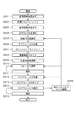
本実施形態による眼底撮影装置の一態様としての眼底撮影装置100について、図1を用いて説明する。本実施形態の眼底撮影装置100には、OCT光学系、SLO光学系、前眼観察光学系、固視灯光学系、制御部190(制御手段)、表示部198(表示手段)、及び入力部199が設けられている。なお、本実施形態では、光学系の全体は、主にミラーを用いた反射光学系で構成されている。
(Device configuration)
A fundus imaging apparatus 100 as one aspect of the fundus imaging apparatus according to the present embodiment will be described with reference to FIG. The fundus imaging apparatus 100 of this embodiment includes an OCT optical system, an SLO optical system, an anterior eye observation optical system, a fixation lamp optical system, a control unit 190 (control unit), a display unit 198 (display unit), and an input unit. 199 is provided. In the present embodiment, the entire optical system is mainly composed of a reflective optical system using a mirror.

また、制御部190は、汎用のコンピュータを用いて構成されてもよいし、眼底撮影装置100の専用のコンピュータとして構成されてもよい。同様に表示部198と入力部199はそれぞれ汎用のディスプレイとマウスやキーボードを用いて構成されてもよいし、装置専用のモニタと操作パネルやボタンとして構成されてもよい。なお、制御部190、表示部198、入力部199は、OCT光学系、SLO光学系、前眼観察光学系、及び固視灯光学系を備えた撮影部と別個に構成されてもよいし、一体的に構成されてもよい。   The control unit 190 may be configured using a general-purpose computer, or may be configured as a dedicated computer for the fundus imaging apparatus 100. Similarly, the display unit 198 and the input unit 199 may be configured using a general-purpose display, a mouse, and a keyboard, respectively, or may be configured as a device-dedicated monitor, an operation panel, and buttons. The control unit 190, the display unit 198, and the input unit 199 may be configured separately from the imaging unit including the OCT optical system, the SLO optical system, the anterior eye observation optical system, and the fixation lamp optical system, You may comprise integrally.

まず、眼底撮影装置100のOCT光学系について説明する。光源101は、光(低コヒーレント光)を発生させるための光源である。本実施形態では、光源101として、中心波長が830nm、帯域が50nmであるSLD(Super Luminescent Diode)を用いている。本実施形態ではSLDを選択したが、光源の種類としては、低コヒーレント光を出射できる光源であればよく、ASE(Amplified Spontaneous Emission)等も用いることができる。なお、光源101は制御部190に接続されており、制御部190によって制御される。   First, the OCT optical system of the fundus imaging apparatus 100 will be described. The light source 101 is a light source for generating light (low coherent light). In this embodiment, an SLD (Super Luminescent Diode) having a center wavelength of 830 nm and a band of 50 nm is used as the light source 101. Although the SLD is selected in the present embodiment, the light source may be any light source that can emit low-coherent light, and ASE (Amplified Spontaneous Emission) or the like can also be used. The light source 101 is connected to the control unit 190 and is controlled by the control unit 190.

また、光源101から出射される光の波長は、眼を測定することを鑑みて近赤外光に対応する波長とすることができる。さらに光源101から出射される光の波長は、得られる断層画像の横方向の分解能に影響するため、なるべく短波長とすることができ、本実施形態では中心波長を830nmとする。なお、観察対象の測定部位によっては、他の波長を選んでもよい。また、波長の帯域は広いほど深さ方向の分解能が良くなる。一般的に中心波長が830nmの場合、50nmの帯域では6μmの分解能、100nmの帯域では3μmの分解能である。なお、光源101の中心波長や帯域はこれに限られず、所望の構成に応じて変更されてよい。   Further, the wavelength of light emitted from the light source 101 can be set to a wavelength corresponding to near-infrared light in view of measuring the eye. Furthermore, since the wavelength of the light emitted from the light source 101 affects the lateral resolution of the obtained tomographic image, it can be made as short as possible. In this embodiment, the center wavelength is set to 830 nm. Other wavelengths may be selected depending on the measurement site to be observed. The wider the wavelength band, the better the resolution in the depth direction. In general, when the center wavelength is 830 nm, the resolution is 6 μm in the 50 nm band and 3 μm in the 100 nm band. The central wavelength and band of the light source 101 are not limited to this, and may be changed according to a desired configuration.

光源101から出射された光は、シングルモードファイバー142を通って、光分割手段である光カプラー141に導かれる。光源101から出射された光は、光カプラー141において強度比90:10で分割され、それぞれ参照光103及びOCT測定光104となる。なお、分割の比率はこれに限らず、被検査物に合わせて適切に選択されることができる。   The light emitted from the light source 101 passes through the single mode fiber 142 and is guided to the optical coupler 141 which is a light splitting unit. The light emitted from the light source 101 is divided by the optical coupler 141 at an intensity ratio of 90:10, and becomes the reference light 103 and the OCT measurement light 104, respectively. The division ratio is not limited to this, and can be appropriately selected according to the inspection object.

次に、参照光103の光路について説明する。光カプラー141にて分割された参照光103はシングルモードファイバー143を通って、レンズ151に導かれ、平行光として出射される。次に、参照光103は、分散補償用ガラス159を透過し、ミラー111,112によって、参照ミラーであるミラー124に導かれる。本実施形態では、参照ミラーとして平面ミラーを用いている。ミラー124で反射された光は、再び、ミラー112及びミラー111に順次反射され、分散補償用ガラス159を透過して、光カプラー141に導かれる。   Next, the optical path of the reference light 103 will be described. The reference light 103 divided by the optical coupler 141 is guided to the lens 151 through the single mode fiber 143 and emitted as parallel light. Next, the reference light 103 passes through the dispersion compensation glass 159 and is guided by the mirrors 111 and 112 to the mirror 124 which is a reference mirror. In this embodiment, a plane mirror is used as the reference mirror. The light reflected by the mirror 124 is again sequentially reflected by the mirror 112 and the mirror 111, passes through the dispersion compensation glass 159, and is guided to the optical coupler 141.

分散補償用ガラス159は、OCT測定光104が被検眼Eとレンズ154を往復したときの分散を、参照光103に対して補償することができる。   The dispersion compensation glass 159 can compensate the reference light 103 for dispersion when the OCT measurement light 104 reciprocates between the eye E and the lens 154.

ミラー124は、電動ステージ125に搭載されており、光路長調整手段を構成する。電動ステージ125は、矢印で図示しているように参照光103の光軸方向に移動することができ、ミラー124の位置を移動させることで参照光103の光路長を調整することができる。電動ステージ125は制御部190によって制御される。   The mirror 124 is mounted on the electric stage 125 and constitutes an optical path length adjusting means. The electric stage 125 can move in the optical axis direction of the reference light 103 as shown by an arrow, and the optical path length of the reference light 103 can be adjusted by moving the position of the mirror 124. The electric stage 125 is controlled by the control unit 190.

次に、OCT測定光104の光路について説明する。光カプラー141により分割されたOCT測定光104は、シングルモードファイバー145を介して、レンズ154に導かれ、平行光として出射される。   Next, the optical path of the OCT measurement light 104 will be described. The OCT measurement light 104 divided by the optical coupler 141 is guided to the lens 154 via the single mode fiber 145 and emitted as parallel light.

次に、OCT測定光104は、ダイクロイックミラー177及びビームスプリッター171を透過し、ミラー113,114によって反射され、収差補正手段であるデフォーマブルミラー182に入射する。ここで、デフォーマブルミラー182は、収差測定手段である波面センサ181にて検知した収差に基づいて、OCT測定光104とOCT戻り光105との収差を、ミラー形状を自在に変形させることで補正するミラーデバイスである。   Next, the OCT measurement light 104 passes through the dichroic mirror 177 and the beam splitter 171, is reflected by the mirrors 113 and 114, and enters the deformable mirror 182 as aberration correction means. Here, the deformable mirror 182 corrects the aberration of the OCT measurement light 104 and the OCT return light 105 by freely deforming the mirror shape based on the aberration detected by the wavefront sensor 181 that is an aberration measurement means. It is a mirror device to be used.

本実施形態では、収差補正手段としてデフォーマブルミラーを用いたが、収差補正手段は収差を補正できればよく、液晶を用いた空間光位相変調器等を用いることもできる。また、本実施形態では、収差測定手段としてシャックハルトマン型の波面センサ181を用いている。しかしながら、収差測定手段はこれに限られず、収差を測定するための既知の任意のセンサ等を用いて構成されてよい。デフォーマブルミラー182及び波面センサ181は、制御手段である制御部190により制御される。   In the present embodiment, a deformable mirror is used as the aberration correction unit. However, the aberration correction unit is only required to correct the aberration, and a spatial light phase modulator using liquid crystal can also be used. In this embodiment, a Shack-Hartmann wavefront sensor 181 is used as the aberration measuring means. However, the aberration measuring means is not limited to this, and may be configured using any known sensor or the like for measuring aberration. The deformable mirror 182 and the wavefront sensor 181 are controlled by a control unit 190 which is a control unit.

OCT測定光104は、デフォーマブルミラー182によって反射された後、ミラー115,116によって反射され、ダイクロイックミラー173に入射する。ここで、ダイクロイックミラー173,174は、光の波長に応じて、光源101からの光を反射し、光源102からの光を透過させる。   The OCT measurement light 104 is reflected by the deformable mirror 182, then reflected by the mirrors 115 and 116, and enters the dichroic mirror 173. Here, the dichroic mirrors 173 and 174 reflect the light from the light source 101 and transmit the light from the light source 102 according to the wavelength of the light.

ダイクロイックミラー173で反射されたOCT測定光104は、Xスキャナ132(第2の走査手段)に入射する。OCT測定光104の中心はXスキャナ132の回転中心と一致するように調整されており、Xスキャナ132を回転させることで、OCT測定光104を用いて被検眼Eの網膜Er上を光軸に垂直な方向にスキャンすることができる。ここでは、Xスキャナ132としてガルバノミラーを用いる。Xスキャナ132は、他の任意の偏向ミラーによって構成されてもよい。なお、図示しないがXスキャナ132は制御部190に接続されており、制御部190によって制御される。   The OCT measurement light 104 reflected by the dichroic mirror 173 enters the X scanner 132 (second scanning means). The center of the OCT measurement light 104 is adjusted so as to coincide with the rotation center of the X scanner 132. By rotating the X scanner 132, the OCT measurement light 104 is used to set the retina Er of the eye E to be examined as the optical axis. Scan in the vertical direction. Here, a galvanometer mirror is used as the X scanner 132. The X scanner 132 may be configured by any other deflection mirror. Although not shown, the X scanner 132 is connected to the control unit 190 and is controlled by the control unit 190.

Xスキャナ132によって反射されたOCT測定光104は、ダイクロイックミラー174によって反射された後、ミラー117〜120によって順次反射される。   The OCT measurement light 104 reflected by the X scanner 132 is reflected by the dichroic mirror 174 and then sequentially reflected by the mirrors 117 to 120.

ミラー119,120は、電動ステージ126に搭載されており、第1のフォーカス手段を構成する。電動ステージ126は、矢印で図示しているように、ミラー118,121に近づく又はこれらから離れる方向に移動することができる。電動ステージ126は制御部190により制御される。なお、ミラー119,120は、OCT光学系とSLO光学系の共通光路内に配置されている。そのため、電動ステージ126によりミラー119,120を移動させることで、被検眼Eの視度に対応してOCT測定光104及びSLO測定光106のフォーカス状態を調整することができる。   The mirrors 119 and 120 are mounted on the electric stage 126 and constitute first focusing means. The electric stage 126 can move toward or away from the mirrors 118 and 121 as shown by the arrows. The electric stage 126 is controlled by the control unit 190. The mirrors 119 and 120 are disposed in a common optical path of the OCT optical system and the SLO optical system. Therefore, the focus states of the OCT measurement light 104 and the SLO measurement light 106 can be adjusted corresponding to the diopter of the eye E by moving the mirrors 119 and 120 by the electric stage 126.

本実施形態では、電動ステージ126の移動範囲を160mmとしており、被検眼Eの−12D〜+7Dの視度範囲に対応してOCT測定光104及びSLO測定光106のフォーカス位置を調整することができる。なお、電動ステージ126の移動範囲は所望の構成により任意に設定されてよい。   In this embodiment, the movement range of the electric stage 126 is 160 mm, and the focus positions of the OCT measurement light 104 and the SLO measurement light 106 can be adjusted corresponding to the diopter range of −12D to + 7D of the eye E. . The moving range of the electric stage 126 may be arbitrarily set depending on a desired configuration.

ここで、本実施形態において、OCT光学系とSLO光学系の共通光路に配置される第1のフォーカス手段は、ミラー119,120の反射光学系によるバダル光学系によって構成される。反射光学系を用いることにより、波面センサ181へ不要な迷光が入ることを防ぐことができ、精度のよい収差測定及び収差補正を行うことができる。   Here, in the present embodiment, the first focusing means disposed in the common optical path of the OCT optical system and the SLO optical system is configured by a Badal optical system that is a reflection optical system of the mirrors 119 and 120. By using the reflection optical system, unnecessary stray light can be prevented from entering the wavefront sensor 181, and accurate aberration measurement and aberration correction can be performed.

ミラー120によって反射されたOCT測定光104は、ミラー121,122によって反射され、Yスキャナ133(第1の走査手段)に入射する。OCT測定光104の中心はYスキャナ133の回転中心と一致するように調整されており、Yスキャナ133を回転させることで、OCT測定光104を用いて網膜Er上を光軸及びXスキャナ132のスキャン方向と垂直な方向にスキャンすることができる。ここでは、Yスキャナ133としてガルバノミラーを用いる。Yスキャナ133は、他の任意の偏向ミラーによって構成されてもよい。   The OCT measurement light 104 reflected by the mirror 120 is reflected by the mirrors 121 and 122 and enters the Y scanner 133 (first scanning means). The center of the OCT measurement light 104 is adjusted so as to coincide with the rotation center of the Y scanner 133. By rotating the Y scanner 133, the OCT measurement light 104 is used to move the optical axis on the retina Er and the X scanner 132. It is possible to scan in a direction perpendicular to the scan direction. Here, a galvanometer mirror is used as the Y scanner 133. The Y scanner 133 may be configured by any other deflection mirror.

なお、図示しないがYスキャナ133は制御部190に接続されており、制御部190によって制御される。Xスキャナ132及びYスキャナ133は、OCT測定光104を被検眼Eの眼底上で二次元方向に走査する、OCT走査手段を構成する。   Although not shown, the Y scanner 133 is connected to the control unit 190 and is controlled by the control unit 190. The X scanner 132 and the Y scanner 133 constitute an OCT scanning unit that scans the OCT measurement light 104 on the fundus of the eye E in a two-dimensional direction.

Yスキャナ133によって反射されたOCT測定光104は、ミラー123に反射され、ダイクロイックミラー175,176を透過し、被検眼Eへ入射する。Xスキャナ132、Yスキャナ133、及びミラー117〜123はOCT測定光104を用いて網膜Erをスキャンするための光学系として機能する。当該光学系により、OCT測定光104を用いて、瞳孔Epの付近を支点として網膜Erをスキャンすることができる。   The OCT measurement light 104 reflected by the Y scanner 133 is reflected by the mirror 123, passes through the dichroic mirrors 175 and 176, and enters the eye E to be examined. The X scanner 132, the Y scanner 133, and the mirrors 117 to 123 function as an optical system for scanning the retina Er using the OCT measurement light 104. With this optical system, the retina Er can be scanned using the OCT measurement light 104 around the pupil Ep as a fulcrum.

OCT測定光104は被検眼Eに入射すると、網膜Erによって反射又は散乱され、OCT戻り光105として、OCT測定光104の光路を戻り、再び光カプラー141に導かれる。   When the OCT measurement light 104 enters the eye E, the OCT measurement light 104 is reflected or scattered by the retina Er, returns as the OCT return light 105 through the optical path of the OCT measurement light 104, and is guided to the optical coupler 141 again.

参照光103とOCT戻り光105とは、光カプラー141にて合波され、干渉光となる。ここで、OCT測定光104及びOCT戻り光105の光路長と参照光103の光路長とがほぼ等しい状態となったときに、OCT戻り光105と参照光103は互いに干渉し、干渉光となる。制御部190は電動ステージ125を制御しミラー124を移動させることで、被検眼Eの被測定部によって変わるOCT測定光104及びOCT戻り光105の光路長に参照光103の光路長を合わせることができる。合波された光108(干渉光)は、シングルモードファイバー144から空間光として出射され、レンズ152を通って透過型グレーティング161に導かれる。そして、光108は、透過型グレーティング161によって波長毎に分光され、レンズ153で集光され、ラインカメラ191に入射する。   The reference beam 103 and the OCT return beam 105 are combined by an optical coupler 141 to become interference light. Here, when the optical path lengths of the OCT measurement light 104 and the OCT return light 105 are substantially equal to the optical path length of the reference light 103, the OCT return light 105 and the reference light 103 interfere with each other and become interference light. . The control unit 190 controls the electric stage 125 to move the mirror 124 so that the optical path length of the reference light 103 is matched with the optical path lengths of the OCT measurement light 104 and the OCT return light 105 that change depending on the measurement target part of the eye E. it can. The combined light 108 (interference light) is emitted as spatial light from the single mode fiber 144, and is guided to the transmissive grating 161 through the lens 152. Then, the light 108 is split for each wavelength by the transmission grating 161, condensed by the lens 153, and enters the line camera 191.

ラインカメラ191に入射した光108は、ラインカメラ191上の位置(波長)毎に光強度に応じた電圧信号(干渉信号)に変換される。具体的には、ラインカメラ191上には波長軸上のスペクトル領域の干渉縞が観察されることになる。得られた電圧信号群はデジタル値に変換される。制御部190は、デジタル値に変換された干渉信号にデータ処理を施すことで、被検眼Eの断層情報である断層画像を生成することができる。また、制御部190は、生成した断層画像(断層情報)を表示部198に表示する情報表示制御部を兼ねる。なお、断層画像を生成する際のデータ処理は、干渉信号から断層画像(断層情報)を生成するための既知の任意のデータ処理であってよい。   The light 108 incident on the line camera 191 is converted into a voltage signal (interference signal) corresponding to the light intensity for each position (wavelength) on the line camera 191. Specifically, interference fringes in the spectral region on the wavelength axis are observed on the line camera 191. The obtained voltage signal group is converted into a digital value. The control unit 190 can generate a tomographic image that is tomographic information of the eye E by performing data processing on the interference signal converted into a digital value. The control unit 190 also serves as an information display control unit that displays the generated tomographic image (tomographic information) on the display unit 198. Note that the data processing when generating the tomographic image may be any known data processing for generating a tomographic image (tomographic information) from the interference signal.

なお、シングルモードファイバー142及び143には、偏光調整用パドル183,184が設けられている。偏光調整用パドル183,184はシングルモードファイバー142,143を通る光の偏光を調整することができる。偏光調整用パドル183,184を用いることで、光源101からの光の偏光状態を調整したり、OCT戻り光105と参照光103の偏光状態が一致するように、参照光103の偏光を調整したりすることができる。なお、偏光調整用パドルを設ける位置はこれに限られず、シングルモードファイバー145等に設けられてもよい。   The single mode fibers 142 and 143 are provided with polarization adjustment paddles 183 and 184. The polarization adjustment paddles 183 and 184 can adjust the polarization of light passing through the single mode fibers 142 and 143. By using the polarization adjustment paddles 183 and 184, the polarization state of the light from the light source 101 is adjusted, or the polarization of the reference light 103 is adjusted so that the polarization states of the OCT return light 105 and the reference light 103 match. Can be. The position where the polarization adjustment paddle is provided is not limited to this, and may be provided in the single mode fiber 145 or the like.

ところで、OCT戻り光105は、OCT測定光104の光路を戻る際に、ビームスプリッター171によって分割され、一部が波面センサ181に入射する。波面センサ181は、入射したOCT戻り光105の収差を測定する。本実施形態において、ビームスプリッター171は、OCT戻り光105の一部を反射し、後述するSLO戻り光107を透過させる。これにより、OCT戻り光105の収差を選択的に測定することができる。波面センサ181は制御部190に電気的に接続されている。制御部190は、波面センサ181からの出力をツェルニケ多項式に当てはめることで、波面センサ181によって測定された被検眼Eの有する収差を把握する。   Incidentally, the OCT return light 105 is split by the beam splitter 171 when returning through the optical path of the OCT measurement light 104, and a part of the OCT return light 105 enters the wavefront sensor 181. The wavefront sensor 181 measures the aberration of the incident OCT return light 105. In the present embodiment, the beam splitter 171 reflects a part of the OCT return light 105 and transmits SLO return light 107 described later. Thereby, the aberration of the OCT return light 105 can be selectively measured. The wavefront sensor 181 is electrically connected to the control unit 190. The control unit 190 applies the output from the wavefront sensor 181 to the Zernike polynomial so as to grasp the aberration of the eye E measured by the wavefront sensor 181.

制御部190は、ツェルニケ多項式のデフォーカスの成分について、電動ステージ126を用いてミラー119,120の位置を制御して、被検眼Eの視度を補正する。また、制御部190は、デフォーカス以外の成分については、デフォーマブルミラー182の表面形状を制御して補正する。これにより、制御部190は、高横分解能な断層画像を生成(取得)することができる。   The control unit 190 corrects the diopter of the eye E by controlling the positions of the mirrors 119 and 120 using the electric stage 126 for the defocus component of the Zernike polynomial. Further, the control unit 190 controls and corrects the surface shape of the deformable mirror 182 for components other than defocus. Thereby, the control unit 190 can generate (acquire) a tomographic image with high lateral resolution.

ここで、瞳孔Ep、Xスキャナ132、Yスキャナ133、波面センサ181、及びデフォーマブルミラー182が光学的に共役になるように、ミラー113〜123が配置される。これにより、波面センサ181は被検眼Eの有する収差を測定することができる。   Here, the mirrors 113 to 123 are arranged so that the pupil Ep, the X scanner 132, the Y scanner 133, the wavefront sensor 181, and the deformable mirror 182 are optically conjugate. As a result, the wavefront sensor 181 can measure the aberration of the eye E.

次に、SLO光学系について説明する。光源102は、光源101とは異なる波長の光を発生させるための光源である。本実施形態では、光源102として波長780nmのSLDを用いる。SLO光学系の光源102の種類は、これに限られず、光源102としてLD(Laser Diode)等を用いることもできる。また、光源102の波長もこれに限られず、所望の構成に応じて変更されてよい。なお、光源102は制御部190に接続されており、制御部190によって制御される。   Next, the SLO optical system will be described. The light source 102 is a light source for generating light having a wavelength different from that of the light source 101. In the present embodiment, an SLD having a wavelength of 780 nm is used as the light source 102. The type of the light source 102 of the SLO optical system is not limited to this, and an LD (Laser Diode) or the like can be used as the light source 102. Further, the wavelength of the light source 102 is not limited to this, and may be changed according to a desired configuration. The light source 102 is connected to the control unit 190 and is controlled by the control unit 190.

光源102から出射された光はレンズ155に導かれ、平行光として出射される。レンズ155を透過した光は、ビームスプリッター172に導かれ、透過光と反射光(SLO測定光106)の強度比が90:10で分割される。ビームスプリッター172によって反射されたSLO測定光106は、フォーカスレンズ157及びレンズ158を透過する。   The light emitted from the light source 102 is guided to the lens 155 and emitted as parallel light. The light transmitted through the lens 155 is guided to the beam splitter 172, and is divided at an intensity ratio of 90:10 between the transmitted light and the reflected light (SLO measurement light 106). The SLO measurement light 106 reflected by the beam splitter 172 passes through the focus lens 157 and the lens 158.

フォーカスレンズ157は、電動ステージ127に搭載されており、第2のフォーカス手段を構成する。電動ステージ127は、矢印で図示しているようにSLO測定光106の光軸方向に移動することができ、SLO測定光106のフォーカス状態を調整することができる。電動ステージ127は制御部190によって制御される。   The focus lens 157 is mounted on the electric stage 127 and constitutes a second focus unit. The electric stage 127 can move in the optical axis direction of the SLO measurement light 106 as shown by the arrow, and the focus state of the SLO measurement light 106 can be adjusted. The electric stage 127 is controlled by the control unit 190.

制御部190は、電動ステージ127を制御してフォーカスレンズ157を移動させることで、OCT測定光104のフォーカス位置と異なる位置にSLO測定光106のフォーカス位置を合わせることができる。ここでは、電動ステージ127の移動範囲を10mmとし、当該移動範囲は−2D〜+2Dの視度範囲に対応している。なお、電動ステージ127の移動範囲はこれに限られず、電動ステージ126の移動範囲よりも狭い任意の移動範囲に設定されてよい。   The control unit 190 can adjust the focus position of the SLO measurement light 106 to a position different from the focus position of the OCT measurement light 104 by moving the focus lens 157 by controlling the electric stage 127. Here, the moving range of the electric stage 127 is 10 mm, and the moving range corresponds to a diopter range of −2D to + 2D. The moving range of the electric stage 127 is not limited to this, and may be set to an arbitrary moving range narrower than the moving range of the electric stage 126.

本実施形態では、第1のフォーカス手段を用いてOCT測定光104及びSLO測定光106のフォーカス調整を行い被検眼Eの視度補正を行うため、第2のフォーカス手段のフォーカス調整範囲は狭く抑えることができる。そのため、電動ステージ127の移動範囲は、電動ステージ126の移動範囲に対して狭くすることができる。従って、より小型のステージを用いてOCT光学系及びSLO光学系の焦点位置を異なる位置に合わせることができるため、光学系を小型化することができる。   In the present embodiment, the focus adjustment range of the second focus unit is narrowed because the first focus unit is used to adjust the focus of the OCT measurement light 104 and the SLO measurement light 106 to correct the diopter of the eye E. be able to. Therefore, the movement range of the electric stage 127 can be narrower than the movement range of the electric stage 126. Therefore, since the focal positions of the OCT optical system and the SLO optical system can be adjusted to different positions using a smaller stage, the optical system can be reduced in size.

なお、図1ではフォーカスレンズ157を凸レンズ、レンズ158を凹レンズとして図示しているが、フォーカスレンズ157及びレンズ158の構成はこれに限らない。フォーカスレンズ157を凹レンズ、レンズ158を凸レンズとしてもよいし、両方を凸レンズにして、これらの間に中間像を形成する構成としてもよい。   In FIG. 1, the focus lens 157 is illustrated as a convex lens, and the lens 158 is illustrated as a concave lens. However, the configurations of the focus lens 157 and the lens 158 are not limited thereto. The focus lens 157 may be a concave lens, the lens 158 may be a convex lens, or both may be convex lenses, and an intermediate image may be formed between them.

フォーカスレンズ157及びレンズ158を透過した光は、ダイクロイックミラー177へ向かう。ダイクロイックミラー177は、光の波長に応じて、光源101からの光を透過させ、光源102からの光を反射する。ダイクロイックミラー177で反射されたSLO測定光106は、OCT測定光104との共通光路を通って、ダイクロイックミラー173に入射する。ここで、SLO測定光106とOCT測定光104の共通光路には、ダイクロイックミラー177、ビームスプリッター171、ミラー113,114、デフォーマブルミラー182、ミラー115,116、及びダイクロイックミラー173が含まれる。   The light transmitted through the focus lens 157 and the lens 158 goes to the dichroic mirror 177. The dichroic mirror 177 transmits light from the light source 101 and reflects light from the light source 102 according to the wavelength of light. The SLO measurement light 106 reflected by the dichroic mirror 177 enters the dichroic mirror 173 through a common optical path with the OCT measurement light 104. Here, the common optical path of the SLO measurement light 106 and the OCT measurement light 104 includes a dichroic mirror 177, a beam splitter 171, mirrors 113 and 114, deformable mirror 182, mirrors 115 and 116, and a dichroic mirror 173.

ダイクロイックミラー173,174は、光の波長に応じて、光源101からの光を反射させ、光源102からの光を透過させる。このため、ミラー116で反射されたSLO測定光106は、ダイクロイックミラー173を透過し、Xスキャナ131(第3の走査手段)に入射する。SLO測定光106の中心はXスキャナ131の回転中心と一致するように調整されており、Xスキャナ131を回転させることで、SLO測定光106を用いて網膜Er上を光軸に垂直な方向にスキャンすることができる。なお、図示しないがXスキャナ131は制御部190に接続されており、制御部190によって制御される。Xスキャナ131及びYスキャナ133はSLO測定光106を被検眼Eの眼底上で二次元方向に走査するSLO走査手段を構成する。   The dichroic mirrors 173 and 174 reflect the light from the light source 101 and transmit the light from the light source 102 according to the wavelength of the light. Therefore, the SLO measurement light 106 reflected by the mirror 116 passes through the dichroic mirror 173 and enters the X scanner 131 (third scanning means). The center of the SLO measuring beam 106 is adjusted to coincide with the rotation center of the X scanner 131. By rotating the X scanner 131, the SLO measuring beam 106 is used to move the retina Er in a direction perpendicular to the optical axis. Can be scanned. Although not shown, the X scanner 131 is connected to the control unit 190 and is controlled by the control unit 190. The X scanner 131 and the Y scanner 133 constitute SLO scanning means that scans the SLO measuring light 106 on the fundus of the eye E in a two-dimensional direction.

本実施形態では、ダイクロイックミラー173によりOCT測定光104の光路とSLO測定光106の光路を分岐させ、OCT測定光104のXスキャナ132とSLO測定光106のXスキャナ131を別に配置する構成としている。OCT測定光104のスキャン速度は、ラインカメラ191の読み出し速度により制限される。これに対し、OCT測定光104のXスキャナ132とSLO測定光106のXスキャナ131を別にすることで、SLO測定光106のスキャン速度を上げることができる。これにより、SLO光学系を用いた眼底正面画像の取得のフレームレートを上げることができる。本実施形態では、Xスキャナ131として共振ミラーを用いているが、所望の構成に応じて任意の偏向ミラーを用いてもよい。   In this embodiment, the optical path of the OCT measurement light 104 and the optical path of the SLO measurement light 106 are branched by the dichroic mirror 173, and the X scanner 132 of the OCT measurement light 104 and the X scanner 131 of the SLO measurement light 106 are separately arranged. . The scanning speed of the OCT measurement light 104 is limited by the reading speed of the line camera 191. On the other hand, the scanning speed of the SLO measuring light 106 can be increased by separately providing the X scanner 132 for the OCT measuring light 104 and the X scanner 131 for the SLO measuring light 106. As a result, the frame rate for acquiring the fundus front image using the SLO optical system can be increased. In the present embodiment, a resonance mirror is used as the X scanner 131, but an arbitrary deflection mirror may be used according to a desired configuration.

Xスキャナ131で反射されたSLO測定光106は、ダイクロイックミラー174を透過し、再びOCT測定光104との共通光路を通って被検眼Eへ入射する。ここで、SLO測定光106とOCT測定光104との共通光路には、ダイクロイックミラー174、ミラー117〜122、Yスキャナ133、ミラー123、及びダイクロイックミラー175,176が含まれる。ここで、SLO測定光106とOCT測定光104との共通光路についてまとめると、当該共通光路には、ダイクロイックミラー177〜ダイクロイックミラー173の光路、及びダイクロイックミラー174〜ダイクロイックミラー176の光路が含まれる。   The SLO measurement light 106 reflected by the X scanner 131 passes through the dichroic mirror 174 and enters the eye E again through a common optical path with the OCT measurement light 104. Here, the common optical path of the SLO measurement beam 106 and the OCT measurement beam 104 includes a dichroic mirror 174, mirrors 117 to 122, a Y scanner 133, a mirror 123, and dichroic mirrors 175 and 176. Here, to summarize the common optical path of the SLO measurement light 106 and the OCT measurement light 104, the common optical path includes the optical path of the dichroic mirror 177 to the dichroic mirror 173 and the optical path of the dichroic mirror 174 to the dichroic mirror 176.

SLO測定光106は、被検眼Eに入射すると網膜Erによって反射又は散乱され、SLO戻り光107として、SLO測定光106の光路を戻り、ダイクロイックミラー177で反射された後、ビームスプリッター172を透過する。ビームスプリッター172を透過したSLO戻り光107は、レンズ156で集光されピンホール板178を通過する。ピンホール板178のピンホール位置は眼底と共役な位置に調整されており、ピンホール板178は共役点以外からの不要な光を遮光する共焦点絞りとして作用する。   When entering the eye E, the SLO measurement light 106 is reflected or scattered by the retina Er, returns as the SLO return light 107, returns to the optical path of the SLO measurement light 106, is reflected by the dichroic mirror 177, and then passes through the beam splitter 172. . The SLO return light 107 transmitted through the beam splitter 172 is collected by the lens 156 and passes through the pinhole plate 178. The pinhole position of the pinhole plate 178 is adjusted to a position conjugate with the fundus oculi, and the pinhole plate 178 functions as a confocal stop that blocks unnecessary light from other than the conjugate point.

ピンホール板178を通過したSLO戻り光107は、受光素子192で受光される。本実施形態では、受光素子192としてAPD(Avalanche Photo Diode)を用いるが、所望の構成に応じて他の任意の受光素子が用いられてもよい。受光素子192は受光した光を光強度に応じて電圧信号に変換する。得られた電圧信号群はデジタル値に変換される。制御部190はデジタル値に変換された受光素子192の出力信号にデータ処理を施し、眼底正面画像を生成することができる。また、制御部190は、生成した眼底正面画像を表示部198に表示する。なお、眼底正面画像を生成する際のデータ処理は、受光素子192からの出力信号から眼底正面画像を生成するための既知の任意のデータ処理であってよい。   The SLO return light 107 that has passed through the pinhole plate 178 is received by the light receiving element 192. In the present embodiment, an APD (Avalanche Photo Diode) is used as the light receiving element 192, but any other light receiving element may be used according to a desired configuration. The light receiving element 192 converts the received light into a voltage signal according to the light intensity. The obtained voltage signal group is converted into a digital value. The control unit 190 can perform data processing on the output signal of the light receiving element 192 converted into a digital value, and generate a fundus front image. In addition, the control unit 190 displays the generated fundus front image on the display unit 198. The data processing when generating the fundus front image may be any known data processing for generating the fundus front image from the output signal from the light receiving element 192.

次に、固視灯光学系について説明する。固視灯光学系は、ダイクロイックミラー175及び固視灯パネル194から構成される。   Next, the fixation lamp optical system will be described. The fixation lamp optical system includes a dichroic mirror 175 and a fixation lamp panel 194.

ダイクロイックミラー175は、光の波長に応じて、固視灯パネル194の可視光を反射し、光源101及び光源102からの光を透過させる。これにより、固視灯パネル194に表示されるパターンがダイクロイックミラー175を介して被検眼Eの網膜Erに投影される。固視灯パネル194に所望のパターンを表示することで、被検眼Eの固視方向を指定し、撮影する網膜Erの範囲を設定することができる。本実施形態では、固視灯パネル194として有機ELパネルを用いるが、他のディスプレイが用いられてもよい。なお、固視灯パネル194は制御部190に接続されており、制御部190によって制御される。   The dichroic mirror 175 reflects the visible light of the fixation lamp panel 194 according to the wavelength of the light and transmits the light from the light source 101 and the light source 102. Thereby, the pattern displayed on the fixation lamp panel 194 is projected onto the retina Er of the eye E through the dichroic mirror 175. By displaying a desired pattern on the fixation lamp panel 194, the fixation direction of the eye E can be specified and the range of the retina Er to be photographed can be set. In this embodiment, an organic EL panel is used as the fixation lamp panel 194, but other displays may be used. The fixation lamp panel 194 is connected to the control unit 190 and is controlled by the control unit 190.

次に、前眼観察光学系について説明する。前眼観察光学系は、ダイクロイックミラー176、前眼観察カメラ193及び不図示の前眼照明光源から構成される。   Next, the anterior eye observation optical system will be described. The anterior eye observation optical system includes a dichroic mirror 176, an anterior eye observation camera 193, and an anterior eye illumination light source (not shown).

ダイクロイックミラー176は、光の波長に応じて、前眼照明光源の赤外光を反射させ、固視灯パネル194の可視光、並びに光源101及び光源102からの光を透過させる。前眼観察カメラ193の光軸は、OCT光学系及びSLO光学系の光軸と一致するように調整されている。このため、前眼観察カメラ193からの出力に基づく被検眼Eの前眼部の画像を表示部上で観察して基準位置に合わせることで、被検眼Eに対するOCT光学系及びSLO光学系のX方向及びY方向の位置合わせ(アライメント)を行うことができる。なお、前眼観察カメラ193は制御部190に接続されており、制御部190によって制御される。   The dichroic mirror 176 reflects the infrared light of the anterior eye illumination light source according to the wavelength of light, and transmits the visible light of the fixation lamp panel 194 and the light from the light source 101 and the light source 102. The optical axis of the anterior eye observation camera 193 is adjusted to coincide with the optical axes of the OCT optical system and the SLO optical system. For this reason, the image of the anterior eye part of the eye E to be examined based on the output from the anterior eye observation camera 193 is observed on the display unit and matched with the reference position, so that the X of the OCT optical system and the SLO optical system for the eye E to be examined The alignment in the direction and the Y direction can be performed. The anterior eye observation camera 193 is connected to the control unit 190 and is controlled by the control unit 190.

また、前眼観察カメラ193のフォーカスは、OCT光学系及びSLO光学系のワーキングディスタンス(Z方向の作動距離)と一致したときに、被検眼Eの虹彩にピントが合うように調整されている。そのため、前眼部の画像における虹彩を表示部上で観察してピントを合わせることで、OCT光学系及びSLO光学系のZ方向の位置合わせを行うことができる。本実施形態では前眼照明光源として波長が970nmのLEDを用い、前眼観察カメラ193としてCCDカメラを用いる。しかしながら、前眼照明光源及び前眼観察カメラはこれに限られず、他の光源や撮影素子等を用いることもできる。また、前眼照明光源の波長もこれに限られず、所望の構成に応じて変更されてよい。   Further, the focus of the anterior eye observation camera 193 is adjusted so that the iris of the eye E is in focus when it matches the working distance (working distance in the Z direction) of the OCT optical system and the SLO optical system. Therefore, the OCT optical system and the SLO optical system can be aligned in the Z direction by observing the iris in the anterior eye image on the display unit and focusing. In this embodiment, an LED having a wavelength of 970 nm is used as the anterior eye illumination light source, and a CCD camera is used as the anterior eye observation camera 193. However, the anterior eye illumination light source and the anterior eye observation camera are not limited to this, and other light sources, imaging elements, and the like can be used. Further, the wavelength of the anterior illumination light source is not limited to this, and may be changed according to a desired configuration.

(撮影範囲の関係)
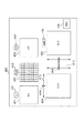
次に、図2を参照して、本実施形態におけるOCT光学系とSLO光学系の撮影範囲の関係について説明する。図2において、実線がOCT光学系の撮影範囲220、破線の枠内がSLO光学系の撮影範囲210を示しており、OCT光学系で1ライン撮影したときのOCT光学系の撮影範囲220とSLO光学系の撮影範囲210との関係を模式的に示している。
(Relationship of shooting range)
Next, the relationship between the imaging ranges of the OCT optical system and the SLO optical system in this embodiment will be described with reference to FIG. In FIG. 2, the solid line indicates the imaging range 220 of the OCT optical system, and the inside of the broken line indicates the imaging range 210 of the SLO optical system, and the imaging range 220 and SLO of the OCT optical system when one line is captured with the OCT optical system. The relationship with the imaging | photography range 210 of an optical system is shown typically.

OCT光学系とSLO光学系は、Yスキャナ133を共通光路に配置しているため、Y方向(図2の紙面上下方向)には同時にスキャンされる。一方、Xスキャナとしては、Xスキャナ132とXスキャナ131の別々のスキャナを用いているため、OCT光学系とSLO光学系のX方向(図2の紙面左右方向)の撮影範囲はそれぞれ独立に設定されることができる。例えば、図2では、SLO光学系の撮影範囲210の略中央にOCT光学系の撮影範囲220を設定しているが、X方向の撮影範囲の関係はこれに限らない。OCT光学系の撮影範囲220はSLO光学系の撮影範囲210に関わらず、任意に設定してよい。   In the OCT optical system and the SLO optical system, the Y scanner 133 is disposed in the common optical path, so that scanning is simultaneously performed in the Y direction (the vertical direction in the drawing of FIG. 2). On the other hand, since the X scanner 132 and the X scanner 131 are used as the X scanner, the photographing ranges in the X direction (left and right direction in FIG. 2) of the OCT optical system and the SLO optical system are set independently. Can be done. For example, in FIG. 2, the imaging range 220 of the OCT optical system is set approximately at the center of the imaging range 210 of the SLO optical system, but the relationship between the imaging ranges in the X direction is not limited to this. The imaging range 220 of the OCT optical system may be arbitrarily set regardless of the imaging range 210 of the SLO optical system.

また、Xスキャナ131の共振ミラーは、ガルバノミラーよりスキャン速度が速いため、1回のY方向のスキャンの間に、SLO測定光106はX方向に複数回スキャンされる。そのため、例えば、長さLのOCT光学系の撮影範囲(1ライン)をm点のサンプリング(Aスキャン)で撮影し、L×LのSLO撮影範囲をm回のXスキャンで撮影することができる。これにより、OCT光学系で長さLの1ラインの断層画像を撮影する間に、SLO光学系でL×Lの眼底正面画像(二次元画像)を取得することができる。なお、L及びmの数値は、所望の構成に応じて任意に設定されてよい。   In addition, since the resonance mirror of the X scanner 131 has a higher scanning speed than the galvanometer mirror, the SLO measurement light 106 is scanned a plurality of times in the X direction during one Y-direction scan. Therefore, for example, an imaging range (one line) of an OCT optical system having a length L can be imaged by sampling (A scan) at m points, and an L × L SLO imaging range can be imaged by m X scans. . As a result, an L × L fundus front image (two-dimensional image) can be acquired by the SLO optical system while a one-line tomographic image having a length L is captured by the OCT optical system. In addition, the numerical values of L and m may be arbitrarily set according to a desired configuration.

また、3Dボリューム画像を撮影する場合は、Yスキャナ133のスキャンに加えて、Xスキャナ132でOCT測定光104をスキャンし、上述したY方向の1ラインの撮影をXスキャナ132のスキャン位置を変更して繰り返す。例えば、X方向にLの範囲でmライン撮影することで、L×Lの3Dボリューム画像を取得することができる。また、この間にSLO光学系を用いてm枚のL×Lの眼底正面画像(二次元画像)を取得することができる。   In addition, when shooting a 3D volume image, in addition to the scan of the Y scanner 133, the OCT measurement light 104 is scanned by the X scanner 132, and the scan position of the X scanner 132 is changed for the above-described shooting of one line in the Y direction. And repeat. For example, an L × L 3D volume image can be acquired by photographing m lines in the range of L in the X direction. During this period, m L × L fundus front images (two-dimensional images) can be acquired using the SLO optical system.

(トラッキングの手順)
次に、SLO光学系を用いて取得した眼底正面画像(二次元画像)に基づく位置ずれ補正(トラッキング)の方法について説明する。
(Tracking procedure)
Next, a method of positional deviation correction (tracking) based on the fundus front image (two-dimensional image) acquired using the SLO optical system will be described.

本実施形態のトラッキング処理では、制御部190は、OCT光学系を用いて同じ位置のライン断層画像を複数回撮影する際の1回目の撮影時に、SLO光学系を用いて取得した被検眼Eの眼底情報(第1の眼底情報)に基づく眼底正面画像を参照画像とする。次に、制御部190は、OCT光学系を用いた2回目以降の撮影時にSLO光学系を用いて取得した眼底情報(第2の眼底情報)に基づく眼底正面画像を位置ずれ検出のための対象画像とする。制御部190は、参照画像に対する対象画像の位置ずれ量を算出する。位置ずれ量の算出は、パターンマッチング等の画像処理で行うことができる。   In the tracking process of the present embodiment, the control unit 190 uses the OLO optical system to capture the eye E to be examined acquired using the SLO optical system during the first imaging when imaging the line tomographic image at the same position a plurality of times. A fundus front image based on fundus information (first fundus information) is set as a reference image. Next, the control unit 190 uses the fundus front image based on the fundus information (second fundus information) acquired using the SLO optical system during the second and subsequent imaging using the OCT optical system as a target for detecting displacement. An image. The control unit 190 calculates the amount of positional deviation of the target image with respect to the reference image. The calculation of the amount of displacement can be performed by image processing such as pattern matching.

制御部190は、算出された位置ずれ量を補正するように、Xスキャナ132及びYスキャナ133を制御する。これにより、制御部190は、固視微動等による眼底の移動に基づく断層画像の撮影位置のずれを補正する眼底トラッキングを行うことができる。なお、取得された複数枚の同じ位置のライン断層画像は、重ね合わせによる断層画像のノイズ低減処理等に用いることができる。   The control unit 190 controls the X scanner 132 and the Y scanner 133 so as to correct the calculated displacement amount. As a result, the control unit 190 can perform fundus tracking that corrects a shift in the photographing position of the tomographic image based on the movement of the fundus due to fixation fine movement or the like. Note that a plurality of acquired line tomographic images at the same position can be used for noise reduction processing of the tomographic image by overlaying.

この眼底トラッキングは、OCT光学系を用いて3Dボリューム画像を取得する場合も同様に適用することができる。この場合には、前述のように、OCT光学系を用いてX方向の位置を変えながらY方向の1ラインの断層画像を繰り返し取得する。このとき、制御部190は、1回目(1ライン目)の撮影時に取得した被検眼Eの眼底情報に基づく眼底正面画像を参照画像とする。また、制御部190は、2回目(2ライン目)以降の撮影時に取得した眼底情報に基づく眼底正面画像を対象画像とする。制御部190は、参照画像と対象画像の位置ずれ量を算出し、眼底トラッキングを行う。これにより、3Dボリューム画像を取得する場合にも、被検眼Eの網膜Erに対する断層画像の撮影位置のずれを補正することができる。   This fundus tracking can be similarly applied when acquiring a 3D volume image using an OCT optical system. In this case, as described above, a one-line tomographic image in the Y direction is repeatedly acquired using the OCT optical system while changing the position in the X direction. At this time, the control unit 190 uses a fundus front image based on the fundus information of the eye E acquired at the first (first line) imaging as a reference image. Further, the control unit 190 sets the fundus front image based on the fundus information acquired at the time of the second and subsequent (second line) photographing as the target image. The control unit 190 calculates the amount of positional deviation between the reference image and the target image, and performs fundus tracking. Thereby, also when acquiring a 3D volume image, the shift | offset | difference of the imaging position of the tomographic image with respect to the retina Er of the eye E to be examined can be corrected.

なお、参照画像として、OCT光学系を用いた1回目の撮影時に、SLO光学系を用いて取得した眼底正面画像の全域を用いてもよいし、眼底正面画像の部分画像を用いてもよい。同様に、対象画像についても、SLO光学系を用いて取得した眼底正面画像の全域を用いてもよいし、眼底正面画像の部分画像を用いてもよい。なお、対象画像として眼底正面画像の部分画像を用いる場合には、対象画像の取得間隔を短縮することができ、眼底トラッキングの制御レートを上げることができる。これにより、眼底のより速い動きによる位置ずれを補正しやすくなる。   Note that, as the reference image, the entire area of the fundus front image acquired using the SLO optical system at the time of the first imaging using the OCT optical system may be used, or a partial image of the fundus front image may be used. Similarly, for the target image, the entire area of the fundus front image acquired using the SLO optical system may be used, or a partial image of the fundus front image may be used. When a partial image of the fundus front image is used as the target image, the acquisition interval of the target image can be shortened and the fundus tracking control rate can be increased. This makes it easier to correct misalignment due to faster movement of the fundus.

また、ここで、参照画像の画像サイズを対象画像の画像サイズより大きく設定してもよい。この場合、対象画像の画像サイズを小さく抑えて制御レートを維持しつつ、参照画像と対象画像の位置ずれ量が大きくても両画像の重なり領域を大きく確保しやすくなり、眼底の大きな動きによる位置ずれを補正しやすくなる。なお、眼底の動きが遅く、眼底トラッキングの制御レートに余裕がある場合は、対象画像の画像サイズを参照画像の画像サイズより大きく設定してもよい。この場合でも、眼底の大きな動きによる位置ずれの補正がしやすくなる。言い換えると、参照画像及び対象画像の一方の画像サイズを他方の画像サイズより大きく設定することで、眼底の大きな動きによる位置ずれを補正しやすくなる。   Here, the image size of the reference image may be set larger than the image size of the target image. In this case, while maintaining the control rate while keeping the image size of the target image small, it is easy to ensure a large overlap area between the reference image and the target image even if the positional deviation amount between the reference image and the target image is large. It becomes easy to correct the deviation. When the fundus movement is slow and the fundus tracking control rate is sufficient, the image size of the target image may be set larger than the image size of the reference image. Even in this case, it becomes easy to correct a positional shift due to a large movement of the fundus. In other words, by setting one image size of the reference image and the target image to be larger than the other image size, it becomes easy to correct a positional shift due to a large movement of the fundus.

(眼底の撮影手順)
次に、図3及び図4を参照して、眼底撮影装置100における眼底の撮影手順を説明する。図3は、本実施形態に係る眼底の撮影手順のフローチャートであり、図4は表示部198に表示される制御ソフトの画面である。
(Fundus procedure)
Next, with reference to FIGS. 3 and 4, a fundus photographing procedure in the fundus photographing apparatus 100 will be described. FIG. 3 is a flowchart of a fundus photographing procedure according to the present embodiment, and FIG. 4 is a screen of control software displayed on the display unit 198.

まず、ステップS301において、検者が前眼照明光源ボタン411を押すと、制御部190は不図示の前眼照明光源を点灯する。前眼照明光源を点灯すると制御部190は、前眼観察カメラ193の出力に基づいて被検眼Eの前眼部の画像を生成し、表示部198に表示される制御ソフト画面の前眼部画像表示部401に表示させる。   First, in step S301, when the examiner presses the anterior eye illumination light source button 411, the control unit 190 turns on an anterior eye illumination light source (not shown). When the anterior eye illumination light source is turned on, the control unit 190 generates an anterior eye image of the eye E based on the output of the anterior eye observation camera 193, and the anterior eye image of the control software screen displayed on the display unit 198. It is displayed on the display unit 401.

ステップS302において、制御部190は、表示部401に表示された前眼部の画像に基づいて、OCT光学系及びSLO光学系が設けられた撮影部を被検眼Eに対してX、Y、及びZ方向の位置合わせ(前眼XYZアライメント)を行う。具体的には、検者が前眼部の画像を観察し、検者の入力に応じて制御部190が撮影部の不図示の駆動機構を制御して、被検眼Eに対して撮影部のアライメントを行う。前述したように、前眼観察カメラ193は、OCT光学系及びSLO光学系に対してX、Y、及びZ方向の位置が調整されている。そのため、検者は表示部401上に表示された前眼部の画像のXY位置及びピント(Z位置)が合うように撮影部のX、Y、及びZ方向の位置を調整することで、OCT光学系及びSLO光学系のX、Y、及びZ方向の位置合わせを行うことができる。なお、撮影部の位置合わせは不図示の撮影部の駆動機構を検者が操作して行ってもよい。   In step S <b> 302, the control unit 190 performs X, Y, and X on the eye E with respect to the imaging unit provided with the OCT optical system and the SLO optical system based on the anterior segment image displayed on the display unit 401. Alignment in the Z direction (anterior eye XYZ alignment) is performed. Specifically, the examiner observes the image of the anterior segment, and the control unit 190 controls a driving mechanism (not shown) of the imaging unit according to the input of the examiner, so that the imaging unit Align. As described above, the position of the anterior eye observation camera 193 in the X, Y, and Z directions is adjusted with respect to the OCT optical system and the SLO optical system. Therefore, the examiner adjusts the position of the imaging unit in the X, Y, and Z directions so that the XY position and the focus (Z position) of the image of the anterior segment displayed on the display unit 401 are aligned, thereby obtaining the OCT. The alignment of the optical system and the SLO optical system in the X, Y, and Z directions can be performed. The positioning of the imaging unit may be performed by an examiner operating a driving mechanism of the imaging unit (not shown).

前眼XYZアライメントが完了したら、ステップS303において、検者が前眼照明光源ボタン411を再度押すことに応じて、制御部190が前眼照明光源を消灯する。   When the anterior eye XYZ alignment is completed, in step S303, the control unit 190 turns off the anterior eye illumination light source in response to the examiner pressing the anterior eye illumination light source button 411 again.

前眼照明光源を消灯したら、ステップS304において、検者が制御ソフト画面の光源ボタン412を押すことに応じて、制御部190がOCT光学系の光源101及びSLO光学系の光源102を点灯する。なお、OCT光学系の光源101を点灯するタイミングは、これに限らない。例えば、後述するステップS306のラフフォーカス調整の後に光源101を点灯してもよい。   When the anterior eye illumination light source is turned off, in step S304, the control unit 190 turns on the light source 101 of the OCT optical system and the light source 102 of the SLO optical system in response to the examiner pressing the light source button 412 on the control software screen. Note that the timing of turning on the light source 101 of the OCT optical system is not limited to this. For example, the light source 101 may be turned on after rough focus adjustment in step S306 described later.

SLO光学系の光源102が点灯したら、ステップ305において、検者が行う固視標位置の設定に応じて固視灯パネル194に表示する固視標の位置を設定し、撮影する網膜Erの範囲を設定する。具体的には検者は制御ソフト画面の固視灯位置調整部402のグリッドに対し、入力部199を用いて所望の位置を指定することで、指定された位置に対応した固視灯パネル194の領域に十字の固視標を点灯する。   When the light source 102 of the SLO optical system is turned on, in step 305, the position of the fixation target displayed on the fixation lamp panel 194 is set according to the fixation target position setting performed by the examiner, and the range of the retina Er to be photographed. Set. Specifically, the examiner designates a desired position using the input unit 199 with respect to the grid of the fixation lamp position adjustment unit 402 on the control software screen, thereby fixing the fixation lamp panel 194 corresponding to the designated position. Turn on the cross fixation target in the area of.

次に制御部190は受光素子192の出力に基づいて眼底正面画像を生成し、制御ソフト画面の眼底表示部405に表示させる。ステップS306において、制御部190は、405に表示される眼底正面画像に基づく検者の入力に応じて、SLO光学系及びOCT光学系の大よそのフォーカス調整(ラフフォーカス調整)を行う。   Next, the control unit 190 generates a fundus front image based on the output of the light receiving element 192 and displays it on the fundus display unit 405 of the control software screen. In step S <b> 306, the control unit 190 performs general focus adjustment (rough focus adjustment) of the SLO optical system and the OCT optical system in accordance with the examiner's input based on the fundus front image displayed on 405.

具体的には、検者が表示部405の眼底正面画像を観察し、制御ソフト画面のフォーカス調整入力部415のフォーカス調整バー416を動かすことに応じて、制御部190が電動ステージ126を移動させる。電動ステージ126及びミラー119,120は、OCT測定光104とSLO測定光106との共通光路に配置されており、SLO測定光106のフォーカス調整を行うことにより、OCT測定光104も同時にラフフォーカス調整が行われる。ここでは、眼底正面画像の輝度が最大になるようにフォーカス調整を行う。   Specifically, the control unit 190 moves the electric stage 126 according to the examiner observing the fundus front image of the display unit 405 and moving the focus adjustment bar 416 of the focus adjustment input unit 415 of the control software screen. . The motorized stage 126 and the mirrors 119 and 120 are disposed in a common optical path for the OCT measurement light 104 and the SLO measurement light 106. By adjusting the focus of the SLO measurement light 106, the OCT measurement light 104 is also simultaneously adjusted for rough focus. Is done. Here, focus adjustment is performed so that the luminance of the fundus front image is maximized.

なお、この際、制御部190は、SLO光学系に設けられた電動ステージ127を予め設定された初期状態の位置に配置しておく。ここでは、電動ステージ127の初期状態の位置として、OCT測定光104とSLO測定光106のフォーカス位置が略一致するような電動ステージ127の位置が設定されている。   At this time, the control unit 190 places the electric stage 127 provided in the SLO optical system at a preset initial position. Here, as the position of the electric stage 127 in the initial state, the position of the electric stage 127 is set such that the focus positions of the OCT measurement light 104 and the SLO measurement light 106 substantially coincide.

ラフフォーカス調整を行ったら、ステップS307において、制御部190は、制御ソフト画面に表示される波面センサ181の表示部403に表示されたハルトマン像の位置に基づく検者の入力に応じて、被検眼Eに対する撮影部のXYファインアライメントを行う。XYファインアライメントでは、検者が表示部403のハルトマン像の位置を観察し、制御部190が検者の入力に応じて被検眼Eに対し撮影部のX方向及びY方向の細密な位置合わせを行う。   After performing the rough focus adjustment, in step S307, the control unit 190 determines the eye to be examined according to the input of the examiner based on the position of the Hartmann image displayed on the display unit 403 of the wavefront sensor 181 displayed on the control software screen. XY fine alignment of the photographing unit with respect to E is performed. In the XY fine alignment, the examiner observes the position of the Hartmann image on the display unit 403, and the control unit 190 performs fine alignment in the X and Y directions of the imaging unit with respect to the eye E according to the examiner's input. Do.

ここで波面センサ181は、波面センサ181の中心位置がOCT光学系及びSLO光学系の光軸と合うように調整されている。そのため、検者はハルトマン像が波面センサ181の中心に合うように、被検眼Eに対して撮影部の位置を調整することで、OCT光学系及びSLO光学系のX方向及びY方向の位置合わせを行うことができる。なお、表示部403には、波面センサ181の中心位置に対応する指標等及びハルトマン像が表示されてよい。   Here, the wavefront sensor 181 is adjusted so that the center position of the wavefront sensor 181 matches the optical axes of the OCT optical system and the SLO optical system. Therefore, the examiner adjusts the position of the imaging unit with respect to the eye E so that the Hartmann image is aligned with the center of the wavefront sensor 181, thereby aligning the OCT optical system and the SLO optical system in the X direction and the Y direction. It can be performed. The display unit 403 may display an index or the like corresponding to the center position of the wavefront sensor 181 and a Hartmann image.

XYファインアライメントを行ったら、ステップS308において、検者が制御ソフト画面の波面補正ボタン412を押すことに応じて、制御部190がデフォーマブルミラー182による波面補正を開始する。ここで制御部190は、波面センサ181で測定された収差に基づいてデフォーマブルミラー182の形状を変形させ、デフォーカス成分以外の被検眼Eの収差を補正する。ここで、デフォーマブルミラーを用いた収差補正の手法に関しては、既存の手法により行ってよいため、説明を省略する。   After performing the XY fine alignment, in step S308, the control unit 190 starts wavefront correction by the deformable mirror 182 in response to the examiner pressing the wavefront correction button 412 on the control software screen. Here, the control unit 190 deforms the shape of the deformable mirror 182 based on the aberration measured by the wavefront sensor 181 to correct the aberration of the eye E other than the defocus component. Here, the aberration correction method using the deformable mirror may be performed by an existing method, and thus the description thereof is omitted.

デフォーマブルミラー182は、OCT測定光104とSLO測定光106との共通光路に配置されている。このため、OCT測定光104についてデフォーマブルミラー182の形状を変形させて被検眼Eの収差を補正することにより、SLO測定光106についても被検眼Eの収差を補正することができる。   The deformable mirror 182 is disposed in a common optical path for the OCT measurement light 104 and the SLO measurement light 106. For this reason, the aberration of the eye E can be corrected also for the SLO measurement light 106 by correcting the aberration of the eye E by changing the shape of the deformable mirror 182 for the OCT measurement light 104.

波面補正が開始されたら、ステップS309において、制御部190は参照光103の光路長を調整する。具体的には、検者が制御ソフト画面の参照光路長調整部413の参照光路長調整バー414を動かすことに応じて、制御部190が電動ステージ125を制御して参照光103の光路長を調整する。ここでは、制御部190は、OCT光学系を用いて取得された断層画像を制御ソフト画面の断層画像表示部404に表示し、検者による入力に応じて、断層画像における所望の層の像が断層画像表示領域内の所望の位置に合うように、参照光103の光路長を調整する。   When the wavefront correction is started, the control unit 190 adjusts the optical path length of the reference light 103 in step S309. Specifically, when the examiner moves the reference optical path length adjustment bar 414 of the reference optical path length adjustment unit 413 on the control software screen, the control unit 190 controls the electric stage 125 to change the optical path length of the reference light 103. adjust. Here, the control unit 190 displays the tomographic image acquired using the OCT optical system on the tomographic image display unit 404 of the control software screen, and an image of a desired layer in the tomographic image is displayed according to the input by the examiner. The optical path length of the reference light 103 is adjusted so as to match a desired position in the tomographic image display area.

参照光103の光路長が調整されたら、ステップS310において、制御部190はSLO光学系及びOCT光学系のフォーカス調整を行う。具体的には、検者が眼底正面画像および断層画像に基づいてフォーカス調整バー416を動かすことに応じて制御部190が電動ステージ126を制御してSLO光学系とOCT光学系の細密なフォーカス調整を行う。高横分解能の補償光学SLOの光学系では、眼底における測定光のNAが大きく焦点深度が浅いため、網膜Erの深さ方向について合焦位置付近の領域のみが画像化される。ステップS310では特に眼底正面画像について、検者が意図する網膜Erの深さ位置の画像が取得されるよう、フォーカス調整を行う。例えば、網膜表層の神経線維層を撮影したい場合、眼底正面画像に神経線維が描出されるよう、制御部190が電動ステージ126を制御してフォーカスを調整する。   When the optical path length of the reference light 103 is adjusted, in step S310, the control unit 190 performs focus adjustment of the SLO optical system and the OCT optical system. Specifically, when the examiner moves the focus adjustment bar 416 based on the fundus front image and the tomographic image, the control unit 190 controls the electric stage 126 to finely adjust the focus of the SLO optical system and the OCT optical system. I do. In the optical system of the compensation optical SLO with high lateral resolution, since the NA of the measurement light at the fundus is large and the depth of focus is shallow, only the region near the in-focus position in the depth direction of the retina Er is imaged. In step S310, focus adjustment is performed so that an image of the depth position of the retina Er intended by the examiner is acquired particularly for the fundus front image. For example, when a nerve fiber layer on the surface layer of the retina is to be imaged, the control unit 190 controls the electric stage 126 to adjust the focus so that the nerve fiber is depicted in the fundus front image.

眼底正面画像のフォーカスが調整されたら、ステップS311において、検者が制御ソフト画面の撮影ボタン418を押すことに応じて、制御部190は眼底トラッキングを実行しながら、同時に眼底断層画像及び眼底正面画像の取得を行う。具体的には、眼球運動検出手段として機能する制御部190が、上述のように、SLO光学系を用いて取得した眼底正面画像の特徴点から位置ずれ量を算出し、算出したずれ量に基づいてXスキャナ132及びYスキャナ133を制御することにより眼底トラッキングを行う。これと同時にOCT測定光104と参照光103との干渉光(光108)は、ラインカメラ191で受光され、電圧信号に変換される。さらに、得られた電圧信号群はデジタル値に変換されて、制御部190にてデータの保存及び処理が行われる。制御部190は干渉光に基づくデータを処理することで眼底断層画像を生成する。また、SLO戻り光107は、受光素子192で受光され、電圧信号に変換される。さらに、得られた電圧信号群はデジタル値に変換されて、制御部190にてデータの保存及び処理が行われる。制御部190はSLO戻り光107に基づくデータを処理することで眼底正面画像を生成する。眼底トラッキングと画像取得の同時実行により眼底撮影装置100は、画像の重ね合わせによるノイズ処理に用いる複数画像や、動画、断層画像の3Dボリューム等を、位置ずれを小さく抑えて取得できる。所定の数の平面画像と断層画像の取得が完了すると、制御部190は眼底トラッキングを終了する。なお、ステップ311での撮影は主に眼底正面画像取得を目的とした撮影である。同時に取得される断層画像はOCT測定光104とSLO測定光106のフォーカス位置が略一致しているから、眼底正面画像に映る網膜Erの深さ位置に対応した層にフォーカスが合った断層画像となる。   When the focus of the fundus front image is adjusted, in step S311, the control unit 190 performs fundus tracking in response to the examiner pressing the photographing button 418 on the control software screen, and simultaneously performs the fundus tomographic image and the fundus front image. Get the. Specifically, as described above, the control unit 190 that functions as an eye movement detection unit calculates a positional shift amount from the feature points of the fundus front image acquired using the SLO optical system, and based on the calculated shift amount. The fundus tracking is performed by controlling the X scanner 132 and the Y scanner 133. At the same time, interference light (light 108) between the OCT measurement light 104 and the reference light 103 is received by the line camera 191 and converted into a voltage signal. Further, the obtained voltage signal group is converted into a digital value, and data is stored and processed in the control unit 190. The control unit 190 generates a fundus tomographic image by processing data based on the interference light. Further, the SLO return light 107 is received by the light receiving element 192 and converted into a voltage signal. Further, the obtained voltage signal group is converted into a digital value, and data is stored and processed in the control unit 190. The control unit 190 processes the data based on the SLO return light 107 to generate a fundus front image. By simultaneously executing fundus tracking and image acquisition, the fundus imaging apparatus 100 can acquire a plurality of images used for noise processing by image superposition, a moving image, a 3D volume of a tomographic image, and the like with a small positional shift. When the acquisition of the predetermined number of planar images and tomographic images is completed, the control unit 190 ends the fundus tracking. Note that the shooting at step 311 is mainly for the purpose of acquiring the fundus front image. Since the tomographic images acquired at the same time have the focus positions of the OCT measurement light 104 and the SLO measurement light 106 substantially coincident with each other, the tomographic image in which the layer corresponding to the depth position of the retina Er reflected in the fundus front image is in focus Become.

トラッキングの終了処理が終わるとステップ310に戻り、検者が深さ位置を変えて再び眼底正面画像を取得したい場合にはステップS310のSLO光学系及びOCT光学系のフォーカス調整及びステップS311の撮影が繰り返し実行される。   When the tracking end processing is completed, the process returns to step 310, and when the examiner wants to acquire the fundus front image again by changing the depth position, the focus adjustment of the SLO optical system and the OCT optical system in step S310 and the imaging in step S311 are performed. Repeatedly executed.

ここで、ステップS312とステップS310の関係について注釈する。S312とS310は眼底撮影装置100の処理としては全く同じである。但し、検者が目的とするフォーカスの調整状態が異なるためステップ番号は分けて記載している。従ってステップS311からステップS310に戻る矢印と、ステップS312に進む矢印は同じ状態遷移を表しており、遷移はS311でトラッキングの終了処理が完了した段階で発生する。ステップS310は先に記したように、眼底正面画像を検者が意図する深さ位置に合わせることが目的であるのに対し、ステップS312は次に記すように、眼底正面画像をトラッキングに適した位置に調整することが目的である。   Here, the relationship between step S312 and step S310 is annotated. S312 and S310 are exactly the same as the processing of the fundus imaging apparatus 100. However, since the focus adjustment state intended by the examiner is different, the step numbers are described separately. Therefore, the arrow that returns from step S311 to step S310 and the arrow that advances to step S312 represent the same state transition, and the transition occurs when the tracking end processing is completed in S311. As described above, step S310 is intended to match the fundus front image to the depth position intended by the examiner, whereas step S312 is suitable for tracking the fundus front image as described below. The purpose is to adjust the position.

ステップS312では、SLO光学系を用いて取得された眼底正面画像が眼底トラキングに適した画像になるようフォーカス調整が行われる。具体的には、検者がフォーカス調整バー416を動かすことに応じて、制御部190が電動ステージ126を制御する。ここでは、表示部上に表示された眼底正面画像の視細胞のコントラストが高くなるように、フォーカス調整が行われる。なお、SLO光学系のフォーカスを合わせる位置は、視細胞に限らない。SLO光学系のフォーカスを合わせる位置は、所望のトラッキング精度が達成できる為の特徴をもった眼底正面画像が取得できれば良く、血管等、他の特徴点を有する位置であってもよい。   In step S312, focus adjustment is performed so that the fundus front image acquired using the SLO optical system becomes an image suitable for fundus tracking. Specifically, the control unit 190 controls the electric stage 126 in response to the examiner moving the focus adjustment bar 416. Here, focus adjustment is performed so that the contrast of photoreceptor cells in the fundus front image displayed on the display unit is increased. Note that the position where the SLO optical system is focused is not limited to the photoreceptor cell. The focus position of the SLO optical system may be a position having another feature point such as a blood vessel as long as a fundus front image having a characteristic for achieving a desired tracking accuracy can be acquired.

眼底正面画像の視細胞のコントラストが高くなるようフォーカスが調整されたら、制御部190はステップS313においてフォーカス調整のモードを切替える。具体的には、検者がモードを選択する手段である制御ソフト画面のモード切替えボタン417を押下することによりモードが切り替わる。押下前はフォーカス調整バー416を動かすことによりSLO光学系とOCT光学系の両方のフォーカスが調整される第1のモードであるのに対し、押下後はOCT光学系のみが調整される第2のモードとなる。また、表示制御手段でもある制御部190は押下によってモード切替えボタン417を図5の450に示す表示に切替え、ボタン色とテキストで現在のモードを検者に報知する。   When the focus is adjusted so that the contrast of photoreceptor cells in the fundus front image is increased, the control unit 190 switches the focus adjustment mode in step S313. Specifically, the mode is switched when the examiner presses a mode switching button 417 on the control software screen which is a means for selecting the mode. This is the first mode in which the focus of both the SLO optical system and the OCT optical system is adjusted by moving the focus adjustment bar 416 before pressing, whereas only the OCT optical system is adjusted after pressing. It becomes a mode. The control unit 190, which is also a display control unit, switches the mode switching button 417 to a display indicated by 450 in FIG. 5 when pressed, and notifies the examiner of the current mode with the button color and text.

ここで、それぞれのモードについて詳細を説明する。第1のモードではフォーカス調整バー416の操作に伴い、制御部190が共通光路上に設けられた第1のフォーカス手段である電動ステージ126を制御し、SLO光学系とOCT光学系の両方のフォーカスを調整する。この第1のモードはOCTのフォーカスを調整する第1のフォーカス調整手段とSLOのフォーカスを調整する第2のフォーカス調整手段が連動するモードある。第2のモードではフォーカス調整バー416の操作に伴い、制御部190が共通光路上に設けられた第1のフォーカス手段である電動ステージ126を制御する。同時に、共通光路から分岐したSLO光学系の専用光路に配置された第2のフォーカス手段である電動ステージ127も制御する。この時、電動ステージ126による調整を打ち消す方向に電動ステージ127を制御することで、SLO光学系のフォーカス状態を変えることなく、OCT光学系のフォーカスだけを調整することができる。この第2のモードはOCTのフォーカスを調整する第1のフォーカス調整手段のみを制御するモードある。   Here, the details of each mode will be described. In the first mode, in accordance with the operation of the focus adjustment bar 416, the control unit 190 controls the electric stage 126, which is the first focusing means provided on the common optical path, and focuses on both the SLO optical system and the OCT optical system. Adjust. This first mode is a mode in which the first focus adjusting means for adjusting the OCT focus and the second focus adjusting means for adjusting the SLO focus are interlocked. In the second mode, in accordance with the operation of the focus adjustment bar 416, the control unit 190 controls the electric stage 126 that is the first focusing means provided on the common optical path. At the same time, the motorized stage 127, which is the second focusing means arranged in the dedicated optical path of the SLO optical system branched from the common optical path, is also controlled. At this time, by controlling the electric stage 127 in a direction to cancel the adjustment by the electric stage 126, it is possible to adjust only the focus of the OCT optical system without changing the focus state of the SLO optical system. This second mode is a mode for controlling only the first focus adjusting means for adjusting the focus of the OCT.

なお、本実施形態では表示部198に表示されるモード設定部である切替えボタン417が色とテキストの変化によってモードの報知手段も兼ねるが、構成はこれに限らない。例えば図6に示すように、ボタン417が押下されると眼底正面画像表示部405を囲う枠451を表示しても良い。他にも制御ソフトの背景色やデザインの変化、フォーカス調整入力部415の変化などに加え、装置100に付帯するランプや音声機能、検者が認識可能な装置100の挙動変化など、表示部198への表示に限られない他の任意の報知手段で実現可能である。また、モード切替えボタン417も同様にトグルスイッチやチェックボックス等のソフトスイッチでも良いし、装置100に実装されたハードウェアのスイッチやボタン、レバーやタッチパッド、音声認識等の任意の切替え手段が適用可能である。   In this embodiment, the switching button 417, which is a mode setting unit displayed on the display unit 198, also serves as a mode notification unit depending on a change in color and text, but the configuration is not limited thereto. For example, as shown in FIG. 6, when a button 417 is pressed, a frame 451 surrounding the fundus front image display unit 405 may be displayed. In addition to changes in the background color and design of the control software, changes in the focus adjustment input unit 415, etc., a display unit 198 such as lamps attached to the device 100, voice functions, changes in the behavior of the device 100 that can be recognized by the examiner, etc. It is realizable with the other arbitrary alerting | reporting means not restricted to the display to. Similarly, the mode switching button 417 may be a soft switch such as a toggle switch or a check box, or any switching means such as a hardware switch or button, lever, touch pad, or voice recognition mounted on the apparatus 100 can be applied. Is possible.

OCTのフォーカスのみが調整される第2のモードにすると、次にステップS314において、OCT光学系のフォーカス調整を行う。具体的には、検者が断層画像に基づいてフォーカス調整バー416を動かすことに応じて、制御部190が電動ステージ126と127を制御してOCT光学系だけのフォーカス調整を行う。補償光学OCTについても焦点深度の浅さから、網膜Erの深さ方向においてフォーカスが合う範囲は限定的となる。そのため、ステップS314では、特に撮影したい網膜Erの層にOCT測定光104のフォーカスが合うようにフォーカス調整が行われる。例えば、網膜表層の血管を撮影したい場合、断層画像を確認しながらその部分の輝度が最大になるように、制御部190が電動ステージ126と127を制御してOCT測定光104のフォーカスを調整する。ステップS314では第2のモードであるから電動ステージ127は電動ステージ126の調整を打ち消す方向に制御され、SLO光学系のフォーカスはステップS312で調整された位置から変化しない。   In the second mode in which only the OCT focus is adjusted, the focus adjustment of the OCT optical system is performed in step S314. Specifically, in response to the examiner moving the focus adjustment bar 416 based on the tomographic image, the control unit 190 controls the electric stages 126 and 127 to perform focus adjustment only for the OCT optical system. Also in the compensation optical OCT, the range of focus in the depth direction of the retina Er is limited due to the shallow depth of focus. Therefore, in step S314, focus adjustment is performed so that the OCT measurement light 104 is focused on the layer of the retina Er that is particularly desired to be photographed. For example, when a blood vessel on the surface layer of the retina is to be imaged, the control unit 190 controls the electric stages 126 and 127 to adjust the focus of the OCT measurement light 104 so that the luminance of that portion is maximized while checking the tomographic image. . Since step S314 is the second mode, the electric stage 127 is controlled to cancel the adjustment of the electric stage 126, and the focus of the SLO optical system does not change from the position adjusted in step S312.

OCT光学系のフォーカス調整が済んで検者が制御ソフト画面の撮影ボタン418を押下すると、ステップS315に進み、制御部190は眼底トラッキングを実行しながら、同時に眼底断層画像及び眼底正面画像の取得を行う。ここでの処理はステップS311と同じだが、眼底正面画像はステップS312により眼底トラキングに適した網膜Erの深さ位置にフォーカスされた状態を保ちつつ、正面画像とは異なるフォーカス位置で断層画像が取得できる。つまり、補償光学SLOの光学系を用いて取得した眼底正面画像を用いて精度のよい眼底トラッキングを行いながら、補償光学OCTの光学系を用いて、網膜Erの所望の層にフォーカスを合わせて高解像度でSN比のよい眼底断層画像を撮影できる。所定の数の平面画像と断層画像の取得が完了すると、制御部190は眼底トラッキングを終了し、ステップS314に戻る。   When the focus adjustment of the OCT optical system is completed and the examiner presses the photographing button 418 on the control software screen, the process proceeds to step S315, and the control unit 190 simultaneously acquires fundus tomographic images and fundus front images while performing fundus tracking. Do. The processing here is the same as in step S311, but the tomographic image is acquired at a focus position different from the front image while the fundus front image remains focused at the depth position of the retina Er suitable for fundus tracking in step S312. it can. That is, while performing accurate fundus tracking using the fundus front image acquired using the adaptive optics SLO optical system, the adaptive optics OCT optical system is used to focus on the desired layer of the retina Er. A fundus tomographic image having a good SN ratio and high resolution can be taken. When the acquisition of the predetermined number of planar images and tomographic images is completed, the control unit 190 ends the fundus tracking and returns to step S314.

ここで、検者が網膜Erの別の層にフォーカスを変えて再び断層画像を取得したい場合にはステップS314のOCT光学系のフォーカス調整及びステップS315の撮影が繰り返される。   Here, when the examiner wants to change the focus to another layer of the retina Er and acquire a tomographic image again, the focus adjustment of the OCT optical system in step S314 and the imaging in step S315 are repeated.

次に、以下のいずれかのケースでは検者が制御ソフト画面のモード切替えボタン450を押下することにより、ステップS316に進み、フォーカス調整のモードの切替えが実行される。
ケース1:ステップS314とS315を繰返して撮影を進めるにつれ、被検眼や被験者の状態により眼底正面画像がステップS312で調整した眼底トラキングに適した深さ位置から外れたり、コントラストが低下したりした場合
ケース2:ステップS314とS315を繰返して撮影を進めるにつれ、被検眼や被験者の状態により断層画像のコントラスト低下やフォーカス位置の把握が困難となり、一度SLO光学系とOCT光学系を同じフォーカス位置に戻したい場合
ケース3:眼底上の撮影位置を変え、これに伴い眼底正面画像のフォーカスを再調整したい場合
Next, in any of the following cases, when the examiner presses the mode switch button 450 on the control software screen, the process proceeds to step S316, and the focus adjustment mode is switched.
Case 1: When photographing is repeated by repeating steps S314 and S315, the fundus front image deviates from the depth position suitable for fundus tracking adjusted in step S312 or the contrast decreases depending on the state of the subject's eye or the subject. Case 2: As steps S314 and S315 are repeated and imaging proceeds, it becomes difficult to determine the contrast of the tomographic image and the focus position depending on the condition of the subject's eye and the subject. Case 3: Case where the shooting position on the fundus is changed and the focus of the fundus front image is readjusted accordingly

ステップS316では、検者が制御ソフト画面のモード切替えボタン450を押下することにより、SLO光学系とOCT光学系の両方のフォーカスが調整される第1のモードへの切替えが実行される。また、押下によってモード切替えボタンは450の表示から417の表示に戻り、モード1であることを検者に報知する。またステップS316において制御部190は電動ステージ127を制御して、OCT光学系とSLO光学系のフォーカス位置が略一致するような電動ステップ127の初期状態の位置に戻す。これにより前述のケース1、2、3において、それぞれステップS312、S310、S305に戻って再度フォーカス調整を行う際に、前回これらを実施した時と同じく、SLO光学系とOCT光学系のフォーカス位置が略一致した状態でフォーカス調整が可能になる。なお、本実施例ではステージ127だけを初期状態へ帰還することでステップS314において設定されたOCT光学系のフォーカス位置に略一致するようにSLO光学系のフォーカス位置が変更される構成とした。しかしながら、ステージ127の初期状態への帰還と同時にステージ126も位置調整してステップS312で設定されたSLO光学系のフォーカス位置に略一するようにSLO光学系のフォーカス位置を変更しても良い。また、ステージ127の初期状態を設定で可変としても良いし、フォーカスの帰還方式を、帰還しない設定も含めて複数用意して、選択可能としても良い。   In step S316, when the examiner presses the mode switching button 450 on the control software screen, switching to the first mode in which the focus of both the SLO optical system and the OCT optical system is adjusted is executed. Further, when pressed, the mode switching button returns from the display of 450 to the display of 417 to notify the examiner that the mode 1 is set. In step S316, the control unit 190 controls the electric stage 127 to return to the initial position of the electric step 127 so that the focus positions of the OCT optical system and the SLO optical system substantially coincide. As a result, in the cases 1, 2, and 3, when the focus adjustment is performed again after returning to steps S312, S310, and S305, respectively, the focus positions of the SLO optical system and the OCT optical system are the same as when the above were performed. Focus adjustment can be performed in a substantially matched state. In this embodiment, the focus position of the SLO optical system is changed so as to substantially match the focus position of the OCT optical system set in step S314 by returning only the stage 127 to the initial state. However, the focus position of the SLO optical system may be changed so as to be substantially equal to the focus position of the SLO optical system set in step S312 by adjusting the position of the stage 126 simultaneously with the return of the stage 127 to the initial state. In addition, the initial state of the stage 127 may be variable by setting, or a plurality of focus feedback methods may be prepared including a setting that does not perform feedback.

また、本実施形態では、SLO測定光のフォーカスを固定するモードについて説明したが、OCT光学系の光路側にフォーカス機構を設けて、OCT測定光のフォーカスを固定する構成としてもよい。それにより、SLO光学系により異なるフォーカス位置の複数の眼底正面画像を取得できる。   In the present embodiment, the mode for fixing the focus of the SLO measurement light has been described. However, a focus mechanism may be provided on the optical path side of the OCT optical system to fix the focus of the OCT measurement light. Thereby, a plurality of fundus front images at different focus positions can be acquired by the SLO optical system.

以上のように、本実施形態では、補償光学を有するSLOとOCTの複合装置において、SLOとOCTの両フォーカスが連動するモードとOCTのフォーカスとSLOのフォーカスが連動しないモードとを切替えながら撮影する際に、現在のモード、即ち、フォーカス調整の対象画像が検者にとって判りやすくなる。   As described above, in this embodiment, in an SLO / OCT composite apparatus having adaptive optics, shooting is performed while switching between a mode in which both SLO and OCT focus are linked and a mode in which the OCT focus and SLO focus are not linked. At this time, the current mode, that is, the focus adjustment target image is easily understood by the examiner.

[第2の実施形態]
図7乃至14を参照しながら、本発明の第2の実施形態による眼底撮影装置700について説明する。本実施形態はOCTとSLOの各々の専用光路にフォーカス手段を備えた眼底撮影装置において、OCTとSLOのフォーカスが連動するモードとOCTのフォーカスを調整するモードとをフォーカス調整部の表示によって報知することで、現在のモードを検者にとって判りやすくする例である。第1の実施形態とはフォーカス手段の構成とモード報知のための表示内容において異なる。
[Second Embodiment]
A fundus photographing apparatus 700 according to the second embodiment of the present invention will be described with reference to FIGS. In this embodiment, in a fundus imaging apparatus provided with focusing means on the dedicated optical paths of OCT and SLO, the mode in which the focus of OCT and SLO are linked and the mode of adjusting the focus of OCT are notified by display on the focus adjustment unit. This is an example of making the current mode easy to understand for the examiner. It differs from the first embodiment in the configuration of the focusing means and the display contents for mode notification.

(装置構成)
以下、図7を参照して、本実施形態による眼底撮影装置700について、第1の実施形態による眼底撮影装置100との相違点を中心に説明する。図7は本実施形態による眼底撮影装置700の概略的な構成を示す。なお、第1の実施形態による眼底撮影装置100と同様の構成については、同一の参照符号を用いて説明を省略する。
(Device configuration)
Hereinafter, with reference to FIG. 7, the fundus imaging apparatus 700 according to the present embodiment will be described focusing on differences from the fundus imaging apparatus 100 according to the first embodiment. FIG. 7 shows a schematic configuration of a fundus imaging apparatus 700 according to the present embodiment. In addition, about the structure similar to the fundus imaging apparatus 100 by 1st Embodiment, description is abbreviate | omitted using the same referential mark.

眼底撮影装置700の基本構成は、第1の実施形態に係る眼底撮影装置100と同様である。ただし、眼底撮影装置700は、OCT光学系とSLO光学系の共通光路にフォーカス手段を配置せず、OCT光学系の専用光路に第1のフォーカス手段を配置する点で、眼底撮影装置100と異なる。眼底撮影装置700では、OCT光学系とSLO光学系との共通光路から分岐されたOCT光学系の専用光路に、第1のフォーカス手段としてフォーカスレンズ757が配置される。これに伴い、SLO光学系の視度調整範囲を確保できるよう、電動ステージ127は、移動範囲が−12D〜+7Dに対応するよう拡充されている。   The basic configuration of the fundus imaging apparatus 700 is the same as that of the fundus imaging apparatus 100 according to the first embodiment. However, the fundus imaging apparatus 700 is different from the fundus imaging apparatus 100 in that the focus unit is not disposed in the common optical path of the OCT optical system and the SLO optical system, and the first focus unit is disposed in the dedicated optical path of the OCT optical system. . In the fundus imaging apparatus 700, a focus lens 757 is disposed as a first focusing unit on a dedicated optical path of the OCT optical system branched from a common optical path of the OCT optical system and the SLO optical system. Accordingly, the electric stage 127 has been expanded so that the movement range corresponds to −12D to + 7D so that the diopter adjustment range of the SLO optical system can be secured.

本実施形態では、OCT測定光104の光路におけるレンズ154とダイクロイックミラー177との間において、フォーカスレンズ757及びレンズ758が設けられている。フォーカスレンズ757は電動ステージ727に搭載されている。電動ステージ727は制御部190の制御により、矢印で図示しているようにOCT測定光104の光軸方向に移動することができる。   In the present embodiment, a focus lens 757 and a lens 758 are provided between the lens 154 and the dichroic mirror 177 in the optical path of the OCT measurement light 104. The focus lens 757 is mounted on the electric stage 727. The electric stage 727 can be moved in the optical axis direction of the OCT measurement light 104 as shown by an arrow under the control of the control unit 190.

なお、図7ではフォーカスレンズ757を凸レンズ、レンズ758を凹レンズとして図示しているが、フォーカスレンズ757及びレンズ758の構成はこれに限らない。フォーカスレンズ757を凹レンズ、レンズ758を凸レンズとしてもよいし、両方を凸レンズにして、これらの間に中間像を形成する構成としてもよい。   In FIG. 7, the focus lens 757 is shown as a convex lens, and the lens 758 is shown as a concave lens, but the configuration of the focus lens 757 and the lens 758 is not limited to this. The focus lens 757 may be a concave lens, the lens 758 may be a convex lens, or both may be convex lenses, and an intermediate image may be formed between them.

(眼底の撮影手順)
次に、図8及び図9を参照して、本実施形態の眼底撮影装置700における眼底の撮影手順を説明する。図8は、本実施形態に係る眼底の撮影手順のフローチャートであり、図9は表示部198に表示される制御ソフトの画面である。ここでも第1の実施形態と同様のステップや構成については、同一の参照符号を用いて説明を省略する。
(Fundus procedure)
Next, with reference to FIG. 8 and FIG. 9, a fundus photographing procedure in the fundus photographing apparatus 700 of the present embodiment will be described. FIG. 8 is a flowchart of a fundus imaging procedure according to the present embodiment, and FIG. 9 is a screen of control software displayed on the display unit 198. Here, the same reference numerals are used for the same steps and configurations as in the first embodiment, and the description thereof is omitted.

撮影が開始され、ステップS301〜S305において、アライメントや固視灯位置の調整が行われて制御部190が受光素子192の出力に基づいて眼底正面画像を生成し、制御ソフト画面の眼底表示部405に表示させると、処理はステップS806に移行する。   Shooting is started, and in steps S301 to S305, alignment and fixation lamp position adjustment are performed, the control unit 190 generates a fundus front image based on the output of the light receiving element 192, and the fundus display unit 405 of the control software screen. If displayed, the process proceeds to step S806.

ステップS806において、制御部190は、表示部405に表示される眼底正面画像に基づく検者の入力に応じて、SLO光学系及びOCT光学系の大よそのフォーカス調整(ラフフォーカス調整)を行う。具体的には、検者が表示部405の眼底正面画像を観察し、制御ソフト画面のフォーカス調整入力部915のフォーカス調整バー916を動かすことに応じて、制御部190が電動ステージ126と電動ステージ727を移動させる。ここで制御部190は電動ステージ126の駆動によるSLO光学系のフォーカス調整量と、電動ステージ727の駆動によるOCT光学系のフォーカス調整量と略一致させながら両者を駆動する連動駆動を実行する。これにより、SLO測定光106のフォーカス調整を行うことで、OCT測定光104も同時にラフフォーカス調整が行われる。ここでは、眼底正面画像の輝度が最大になるようにフォーカス調整を行う。   In step S806, the control unit 190 performs general focus adjustment (rough focus adjustment) of the SLO optical system and the OCT optical system in accordance with the examiner's input based on the fundus front image displayed on the display unit 405. Specifically, in response to the examiner observing the fundus front image of the display unit 405 and moving the focus adjustment bar 916 of the focus adjustment input unit 915 of the control software screen, the control unit 190 controls the electric stage 126 and the electric stage. 727 is moved. Here, the control unit 190 performs interlocking driving that drives both of the focus adjustment amounts of the SLO optical system driven by the electric stage 126 and the focus adjustment amounts of the OCT optical system driven by the electric stage 727. Thus, by performing focus adjustment of the SLO measurement light 106, the OCT measurement light 104 is also subjected to rough focus adjustment at the same time. Here, focus adjustment is performed so that the luminance of the fundus front image is maximized.

なお、この際、制御部190は、2つの電動ステージ127と727の相対位置を予め設定された初期状態の位置関係に配置しておく。ここでは初期状態の位置関係として、OCT測定光104とSLO測定光106のフォーカス位置が略一致するような両ステージの位置関係が設定されている。   At this time, the control unit 190 places the relative positions of the two electric stages 127 and 727 in a preset initial positional relationship. Here, as the positional relationship in the initial state, the positional relationship between the two stages is set such that the focus positions of the OCT measurement light 104 and the SLO measurement light 106 substantially coincide.

ラフフォーカス調整を行ったら、ステップS307〜S309において、ハルトマン像403の位置に基づくXYファインアライメントから参照光103の光路長の調整を終える。   When the rough focus adjustment is performed, the adjustment of the optical path length of the reference light 103 is completed from the XY fine alignment based on the position of the Hartmann image 403 in steps S307 to S309.

参照光路長調整が済むと、ステップS810において、制御部190はSLO光学系及びOCT光学系のフォーカス調整を行う。具体的には、検者が眼底正面画像および断層画像に基づいてフォーカス調整バー916を動かす。それに応じて制御部190が電動ステージ127及び727をステップS806と同様に連動させた制御をしてSLO光学系とOCT光学系の細密なフォーカス調整を行う。検者が意図する網膜Erの深さ位置の眼底正面画像が取得されるよう、フォーカス調整が行われる。   When the reference optical path length adjustment is completed, in step S810, the control unit 190 performs focus adjustment of the SLO optical system and the OCT optical system. Specifically, the examiner moves the focus adjustment bar 916 based on the fundus front image and the tomographic image. In response to this, the control unit 190 controls the electric stages 127 and 727 in the same manner as in step S806 to perform fine focus adjustment of the SLO optical system and the OCT optical system. Focus adjustment is performed so that the fundus front image at the depth position of the retina Er intended by the examiner is acquired.

眼底正面画像のフォーカスが調整されたら、ステップS311において、検者が制御ソフト画面の撮影ボタン418を押すことに応じて、制御部190は眼底トラッキングを実行しながら、同時に眼底断層画像及び眼底正面画像の取得を行う。所定数の画像取得が終了すると、制御部190は眼底トラッキングを終了し、ステップS810に戻る。   When the focus of the fundus front image is adjusted, in step S311, the control unit 190 performs fundus tracking in response to the examiner pressing the photographing button 418 on the control software screen, and simultaneously performs the fundus tomographic image and the fundus front image. Get the. When the acquisition of the predetermined number of images is completed, the control unit 190 ends the fundus tracking and returns to step S810.

検者が深さ位置を変えて再び眼底正面画像を取得したい場合には、検者の操作に応じてステップS310のSLO光学系及びOCT光学系のフォーカス調整及びステップS311の撮影が繰り返し実行される。   When the examiner wants to acquire the fundus front image again by changing the depth position, the focus adjustment of the SLO optical system and the OCT optical system in step S310 and the imaging in step S311 are repeatedly executed according to the operation of the examiner. .

ここでも第1の実施形態と同様にステップS810とS812は同じ処理であり、眼底正面画像を検者が意図する深さ位置に合わせるか、トラッキングに適した位置に調整するかの目的が異なるだけである。意図した深さの眼底正面画像の取得を全て終えると、検者の操作によってステップS812の工程が実行されることになる。   Here, as in the first embodiment, steps S810 and S812 are the same processing, and only the purpose of adjusting the fundus front image to a depth position intended by the examiner or a position suitable for tracking is different. It is. When all the acquisition of the fundus front image of the intended depth is completed, the process of step S812 is executed by the examiner's operation.

ステップS812では、制御部190はSLO光学系を用いて取得された眼底正面画像が眼底トラキングに適した画像になるようフォーカス調整を行う。具体的には、検者がフォーカス調整バー916を動かすことに応じて、制御部190が電動ステージ127及び727をステップS806と同様に連動して制御する。必要なトラッキング精度を達成するために視細胞のコントラストが高い眼底正面画像になるように、フォーカス調整を行う。   In step S812, the control unit 190 performs focus adjustment so that the fundus front image acquired using the SLO optical system becomes an image suitable for fundus tracking. Specifically, in response to the examiner moving the focus adjustment bar 916, the control unit 190 controls the electric stages 127 and 727 in conjunction with step S806. In order to achieve the required tracking accuracy, focus adjustment is performed so that a fundus front image with high contrast of photoreceptor cells is obtained.

眼底正面画像の視細胞のコントラストが高くなるようフォーカスが調整されたら、制御部190はステップS813においてフォーカス調整のモードを切替える。具体的には、検者が制御ソフト画面のモード切替えボタン419を押下することによりモードが切り替わる。押下前はフォーカス調整バー916を動かすことによりSLO光学系とOCT光学系の両方のフォーカスが連動して調整される第1のモードであるのに対し、押下後はOCT光学系のフォーカスみが調整される第2のモードとなる。また、表示制御手段でもある制御部190は押下によってフォーカス調整入力部を図10の917に示す表示に切替え、フォーカス調整バー916から918の形態変化でいずれのフォーカス調整が有効なモードであるか報知する。第2のモードは、制御部190がフォーカス調整バー918の操作によって電動ステージ727のみを駆動することで、OCT光学系のフォーカスだけが調整される。   When the focus is adjusted so that the contrast of the photoreceptor cells in the fundus front image is increased, the control unit 190 switches the focus adjustment mode in step S813. Specifically, the mode is switched when the examiner presses the mode switching button 419 on the control software screen. This is the first mode in which the focus of both the SLO optical system and the OCT optical system is adjusted in conjunction with each other by moving the focus adjustment bar 916 before pressing, whereas the focus of the OCT optical system is adjusted after pressing. Is the second mode. The control unit 190, which is also a display control unit, switches the focus adjustment input unit to the display indicated by 917 in FIG. 10 when pressed, and notifies which focus adjustment is in effect by changing the form of the focus adjustment bars 916 to 918. To do. In the second mode, only the focus of the OCT optical system is adjusted when the control unit 190 drives only the electric stage 727 by operating the focus adjustment bar 918.

なお、本実施形態では表示部198に表示されるフォーカス調整入力部915がその形態の変化によってモードの報知手段も兼ねるが、構成はこれに限らない。図11に示すように枠461でフォーカス調整入力部の有効範囲を明示するような報知状態や、図12に示すような他方のフォーカス調整バーをグレーアウトしてその無効を明示するような報知状態、図13に示すようなフォーカス調整入力部の表示位置でOCTとSLOのいずれに対して有効であるか明示するような報知状態、図14に示すような画像表示部の枠の色でモードを明示するような報知状態など、任意の報知状態が適用できる。   In this embodiment, the focus adjustment input unit 915 displayed on the display unit 198 also serves as a mode notification unit depending on the change in the form, but the configuration is not limited thereto. As shown in FIG. 11, a notification state in which the effective range of the focus adjustment input unit is clearly indicated by a frame 461, or a notification state in which the other focus adjustment bar as shown in FIG. The notification mode for clearly indicating whether the focus adjustment input unit is effective for OCT or SLO at the display position of the focus adjustment input unit as shown in FIG. 13, and the mode is specified by the color of the frame of the image display unit as shown in FIG. Any notification state, such as a notification state such as, can be applied.

OCT光学系のみが調整される第2のモードになると、次のステップS814に移り、OCT光学系のフォーカス調整が行われる。具体的には、検者が断層画像に基づいてフォーカス調整バー918を動かすことに応じて、制御部190が電動ステージ127を制御してOCT光学系だけのフォーカス調整を行う。撮影したい網膜Erの層にOCT測定光104のフォーカスが合うようにフォーカス調整が行われる。   In the second mode in which only the OCT optical system is adjusted, the process proceeds to the next step S814, and the focus adjustment of the OCT optical system is performed. Specifically, in response to the examiner moving the focus adjustment bar 918 based on the tomographic image, the control unit 190 controls the electric stage 127 to perform focus adjustment only for the OCT optical system. Focus adjustment is performed so that the OCT measurement light 104 is focused on the layer of the retina Er to be photographed.

OCT光学系のフォーカス調整が済んで検者が制御ソフト画面の撮影ボタン418を押下すると、ステップS315に進み、制御部190は眼底トラッキングを実行しながら、同時に眼底断層画像及び眼底正面画像の取得を行う。所定の数の平面画像と断層画像の取得が完了すると、制御部190は眼底トラッキングを終了し、ステップS814に戻る。ここで、検者が網膜Erの別の層にフォーカスを変えて再び断層画像を取得したい場合にはステップS814のOCT光学系のフォーカス調整及びステップS315の撮影が繰り返される。   When the focus adjustment of the OCT optical system is completed and the examiner presses the photographing button 418 on the control software screen, the process proceeds to step S315, and the control unit 190 simultaneously acquires fundus tomographic images and fundus front images while performing fundus tracking. Do. When the acquisition of the predetermined number of planar images and tomographic images is completed, the control unit 190 ends fundus tracking and returns to step S814. Here, when the examiner wants to change the focus to another layer of the retina Er and acquire a tomographic image again, the focus adjustment of the OCT optical system in step S814 and the imaging in step S315 are repeated.

次に、第1の実施形態に記載したいずれかのケースでは検者が制御ソフト画面のモード切替えボタン419を押下することにより、ステップS816に進み、フォーカス調整のモードの切替えが実行される。具体的には、制御部190はフォーカス調整のモードをSLO光学系とOCT光学系の両方のフォーカスが調整される第1のモードに切替える。また、フォーカス調整入力部は917の表示から915の表示に戻し、モード1であることを検者に報知する。さらに制御部190は電動ステージ727を制御して、SLO光学系のフォーカス位置に対してOCT光学系のフォーカス位置を略一致させることで、2つの電動ステージ127と727の相対位置を初期状態の位置関係に戻す。   Next, in any case described in the first embodiment, when the examiner presses the mode switch button 419 on the control software screen, the process proceeds to step S816, and the focus adjustment mode is switched. Specifically, the control unit 190 switches the focus adjustment mode to the first mode in which the focus of both the SLO optical system and the OCT optical system is adjusted. In addition, the focus adjustment input unit returns from the display 917 to the display 915 to notify the examiner that the mode 1 is set. Further, the control unit 190 controls the electric stage 727 so that the focus position of the OCT optical system substantially coincides with the focus position of the SLO optical system, thereby setting the relative position of the two electric stages 127 and 727 to the initial position. Return to relationship.

以上のような報知機能によって、本実施形態では、補償光学を有するSLOとOCTの複合装置において、SLOとOCTの両フォーカスが連動するモードとOCTのフォーカスのみが操作できるモードとを切替えながら撮影する際に、現在のモードが検者にとって判りやすくなる。   With the notification function as described above, in this embodiment, in the SLO and OCT combined apparatus having adaptive optics, shooting is performed while switching between a mode in which both SLO and OCT focus are linked and a mode in which only the OCT focus can be operated. In this case, the current mode becomes easier for the examiner to understand.

[変形例1]
第1の実施形態では、OCT光学系とSLO光学系の共通光路に配置された電動ステージ126に搭載されたミラー119,120を第1のフォーカス手段とし、これらを移動させることによりラフフォーカス調整及びファインフォーカス調整を行った。しかしながら、これらフォーカス調整に用いる第1のフォーカス手段はこれに限らない。例えば、第1のフォーカス手段としてOCT光学系とSLO光学系の共通光路に配置されたデフォーマブルミラー182を用いることもできる。
[Modification 1]
In the first embodiment, the mirrors 119 and 120 mounted on the electric stage 126 disposed in the common optical path of the OCT optical system and the SLO optical system are used as the first focusing means, and these are moved to perform rough focus adjustment and Fine focus adjustment was performed. However, the first focusing means used for these focus adjustments is not limited to this. For example, a deformable mirror 182 disposed in the common optical path of the OCT optical system and the SLO optical system can be used as the first focusing unit.

特にファインフォーカス調整は、デフォーマブルミラー182を変形させることにより行ってもよい。この場合、制御部190は、波面センサ181の測定値に基づいたデフォーマブルミラー182の目標形状に、デフォーカス成分のオフセットを与えて制御する。これにより、被検眼Eの収差を補正しつつ、OCT光学系とSLO光学系のフォーカス位置を変更することができる。なお、ラフフォーカス調整においても、フォーカスの調整量が少なくて済む場合には、同様にデフォーマブルミラー182を用いることができる。   In particular, fine focus adjustment may be performed by deforming the deformable mirror 182. In this case, the control unit 190 controls the target shape of the deformable mirror 182 based on the measurement value of the wavefront sensor 181 by giving a defocus component offset. Thereby, it is possible to change the focus positions of the OCT optical system and the SLO optical system while correcting the aberration of the eye E. In the rough focus adjustment, the deformable mirror 182 can be used in the same manner if the focus adjustment amount is small.

また、第1のフォーカス手段として、フォーカスレンズや電気光学素子、ピエゾ素子、液晶光学素子、可変形状ミラー等、他の任意のフォーカス手段を用いてもよい。   Further, as the first focusing means, any other focusing means such as a focus lens, an electro-optical element, a piezo element, a liquid crystal optical element, a deformable mirror, or the like may be used.

なお、上記実施形態及び変形例では、検者の入力に応じて制御部190が各種アライメントや、光路長調整、フォーカス調整を行った。しかしながら、上述の各種アライメントや、光路長調整、フォーカス調整において用いられた前眼部の画像、眼底正面画像、ハルトマン像、及び断層画像等に基づいて、制御部190が自動的にこれらのアライメントや調整を行ってもよい。この場合には、例えば、制御部190が上述のアライメントや調整と同様に、眼底正面画像の輝度や撮影すべき層等に基づいて、これらのアライメントや調整を行うことができる。   In the embodiment and the modification described above, the control unit 190 performs various types of alignment, optical path length adjustment, and focus adjustment according to the input of the examiner. However, based on the above-described various alignments, the optical path length adjustment, the image of the anterior segment used in the focus adjustment, the fundus front image, the Hartmann image, the tomographic image, and the like, the control unit 190 automatically performs these alignments. Adjustments may be made. In this case, for example, the control unit 190 can perform these alignments and adjustments based on the luminance of the fundus front image, the layer to be photographed, and the like, in the same manner as the alignment and adjustment described above.

また、上記実施形態及び変形例では、OCT光学系として、SLDを光源として用いたスペクトラルドメインOCT(SD−OCT)光学系について述べたが、本発明によるOCT光学系の構成はこれに限られない。例えば、出射光の波長を掃引することができる波長掃引光源を用いた波長掃引型OCT(SS−OCT)光学系等の他の任意の種類のOCT光学系にも本発明を適用することができる。   In the above-described embodiments and modifications, the spectral domain OCT (SD-OCT) optical system using an SLD as a light source has been described as the OCT optical system. However, the configuration of the OCT optical system according to the present invention is not limited thereto. . For example, the present invention can be applied to any other type of OCT optical system such as a wavelength sweep type OCT (SS-OCT) optical system using a wavelength swept light source capable of sweeping the wavelength of emitted light. .

(その他の実施形態)
本発明は、上述の実施形態の1以上の機能を実現するプログラムを、ネットワーク又は記憶媒体を介してシステム又は装置に供給し、そのシステム又は装置のコンピュータにおける1つ以上のプロセッサーがプログラムを読出し実行する処理でも実現可能である。また、1以上の機能を実現する回路(例えば、ASIC)によっても実現可能である。
(Other embodiments)
The present invention supplies a program that realizes one or more functions of the above-described embodiments to a system or apparatus via a network or a storage medium, and one or more processors in a computer of the system or apparatus read and execute the program This process can be realized. It can also be realized by a circuit (for example, ASIC) that realizes one or more functions.

以上、実施形態を参照して本発明について説明したが、本発明は上記実施形態に限定されるものではない。本発明の趣旨に反しない範囲で変更された発明、及び本発明と均等な発明も本発明に含まれる。また、上述の各実施形態及び変形例は、本発明の趣旨に反しない範囲で適宜組み合わせることができる。また、各実施形態及び変形例で説明されている特徴の組み合わせの全てが本発明の解決手段に必須のものとは限らない。   Although the present invention has been described above with reference to the embodiments, the present invention is not limited to the above embodiments. Inventions modified within the scope not departing from the spirit of the present invention and inventions equivalent to the present invention are also included in the present invention. Moreover, each above-mentioned embodiment and modification can be combined suitably in the range which is not contrary to the meaning of this invention. In addition, not all combinations of features described in the embodiments and the modifications are essential for the solution means of the present invention.

Claims (12)

OCT測定光を用いて被検眼の断層情報を取得するOCT光学系と、
SLO測定光を用いて前記被検眼の眼底情報を取得するSLO光学系と、
前記OCT測定光のフォーカスを調整する第1のフォーカス調整手段と、
前記SLO測定光のフォーカスを調整する第2のフォーカス調整手段と、
前記第1のフォーカス調整手段と前記第2のフォーカス調整手段とを制御する制御手段と、
前記第1のフォーカス調整手段と前記第2のフォーカス調整手段とを連動して制御する第1のモードと、前記第1のフォーカス調整手段と前記第2のフォーカス調整手段のいずれか一方を制御する第2のモードから何れかのモードを選択する選択手段と、
前記選択の状態を報知する報知手段を有することを特徴とする眼底撮影装置。
An OCT optical system for acquiring tomographic information of the eye to be examined using OCT measurement light;
An SLO optical system for acquiring fundus information of the eye to be examined using SLO measurement light;
First focus adjustment means for adjusting the focus of the OCT measurement light;
Second focus adjustment means for adjusting the focus of the SLO measurement light;
Control means for controlling the first focus adjustment means and the second focus adjustment means;
The first mode for controlling the first focus adjustment unit and the second focus adjustment unit in conjunction with each other, and one of the first focus adjustment unit and the second focus adjustment unit are controlled. Selecting means for selecting any mode from the second mode;
An ocular fundus imaging apparatus comprising an informing means for informing the selection state.
前記OCT光学系と前記SLO光学系の共通光路上に設けられた第1のフォーカス手段と、
前記SLO光学系の光路上であって前記OCT光学系には含まれない光路上に設けられた第2のフォーカス手段を更に有し、
前記第1のフォーカス調整手段は前記第1のフォーカス手段を調整することによりOCT測定光のフォーカスを調整し、前記第2のフォーカス調整手段は前記第1のフォーカス手段及び第2のフォーカス手段を調整することによりSLO測定光のフォーカスを調整することを特徴とする請求項1に記載の眼底撮影装置。
First focusing means provided on a common optical path of the OCT optical system and the SLO optical system;
A second focusing means provided on the optical path of the SLO optical system and not included in the OCT optical system;
The first focus adjustment means adjusts the focus of the OCT measurement light by adjusting the first focus means, and the second focus adjustment means adjusts the first focus means and the second focus means. The fundus imaging apparatus according to claim 1, wherein the focus of the SLO measurement light is adjusted.
前記OCT測定光の収差を測定する収差測定手段と、
前記共通光路上に設けられ、前記収差を補正する収差補正手段と、
を更に備え、
前記制御手段は、前記収差測定手段により測定された前記収差に基づいて、前記収差補正手段を制御することを特徴とする請求項1または2のいずれか一項に記載の眼底撮影装置。
An aberration measuring means for measuring the aberration of the OCT measurement light;
An aberration correction unit that is provided on the common optical path and corrects the aberration;
Further comprising
The fundus imaging apparatus according to claim 1, wherein the control unit controls the aberration correction unit based on the aberration measured by the aberration measurement unit.
前記第1のフォーカス手段の少なくとも一部として前記収差補正手段が用いられることを特徴とする請求項3に記載の眼底撮影装置。   The fundus imaging apparatus according to claim 3, wherein the aberration correction unit is used as at least part of the first focusing unit. モード設定部を表示手段に表示する表示制御手段を更に有し、
前記選択手段は、前記モード設定部が設定されることにより何れかを選択することを特徴とする請求項1乃至4のいずれか一項に記載の眼底撮影装置。
It further has display control means for displaying the mode setting section on the display means,
The fundus imaging apparatus according to any one of claims 1 to 4, wherein the selection unit selects one of the modes by setting the mode setting unit.
前記被検眼の断層情報と前記被検眼の眼底情報を表示手段に表示する情報表示制御手段を更に有し、
前記報知手段は、前記情報表示制御手段に表示する情報を前記選択の状態に応じて変えることを特徴とする請求項1乃至5のいずれか一項に記載の眼底撮影装置。
Further comprising information display control means for displaying the tomographic information of the eye to be examined and the fundus information of the eye to be examined on a display means,
The fundus imaging apparatus according to claim 1, wherein the notification unit changes information displayed on the information display control unit according to the selection state.
フォーカス調整入力部を表示手段に表示する手段を更に有し、
前記報知手段は、前記フォーカス調整入力部の表示を前記選択の状態に応じて変えることを特徴とする請求項1乃至6のいずれか一項に記載の眼底撮影装置。
A means for displaying the focus adjustment input section on the display means;
The fundus imaging apparatus according to claim 1, wherein the notification unit changes the display of the focus adjustment input unit in accordance with the selection state.
前記SLO測定光を前記被検眼の眼底上で二次元方向に走査する走査手段を更に有し、
前記制御手段は、
前記被検眼の前記眼底情報に基づいて眼底の動きを検出し、
前記検出した眼底の動きに基づいて前記走査手段を制御することを特徴とする請求項1乃至7のいずれか一項に記載の眼底撮影装置。
Scanning means for scanning the SLO measurement light in a two-dimensional direction on the fundus of the eye to be examined;
The control means includes
Detecting the movement of the fundus based on the fundus information of the eye to be examined;
The fundus imaging apparatus according to claim 1, wherein the scanning unit is controlled based on the detected movement of the fundus.
前記制御手段は前記第2のモードから前記第1のモードにモードを切替えるときに、前記OCT測定光のフォーカスと前記SLO測定光のフォーカスを予め決められた位置関係に調整することを特徴とする請求項1乃至8のいずれか一項に記載の眼底撮影装置。   The control means adjusts the focus of the OCT measurement light and the focus of the SLO measurement light to a predetermined positional relationship when switching the mode from the second mode to the first mode. The fundus imaging apparatus according to any one of claims 1 to 8. 前記予め決められた位置関係は、前記OCT測定光のフォーカスと前記SLO測定光のフォーカスのうちのいずれか一方をもう一方のフォーカスと一致させた位置であることを特徴とする請求項9に記載の眼底撮影装置。   10. The predetermined positional relationship is a position where one of the focus of the OCT measurement light and the focus of the SLO measurement light coincides with the other focus. Fundus photographing device. OCT測定光を用いて被検眼の断層情報を取得するOCT光学系と、SLO測定光を用いて前記被検眼の眼底情報を取得するSLO光学系と、前記OCT測定光のフォーカスを調整する第1のフォーカス調整手段と、前記SLO測定光のフォーカスを調整する第2のフォーカス調整手段と、前記第1のフォーカス調整手段と前記第2のフォーカス調整手段とを制御する制御手段とを有する眼底撮影装置の制御方法であって、
前記第1のフォーカス調整手段と前記第2のフォーカス調整手段とを連動して制御する第1のモードと、前記第1のフォーカス調整手段と前記第2のフォーカス調整手段のいずれか一方を制御する第2のモードから何れかのモードを選択する工程と、
前記選択の状態を報知する報知工程を有することを特徴とする眼底撮影装置の制御方法。
An OCT optical system that obtains tomographic information of the eye to be examined using OCT measurement light, an SLO optical system that obtains fundus information of the eye to be examined using SLO measurement light, and a first that adjusts the focus of the OCT measurement light. Fundus imaging apparatus comprising: a focus adjustment unit; a second focus adjustment unit that adjusts the focus of the SLO measurement light; and a control unit that controls the first focus adjustment unit and the second focus adjustment unit. Control method,
The first mode for controlling the first focus adjustment unit and the second focus adjustment unit in conjunction with each other, and one of the first focus adjustment unit and the second focus adjustment unit are controlled. Selecting any mode from the second mode;
A method for controlling a fundus imaging apparatus, comprising: a notification step of notifying the selection state.
請求項1乃至10に記載の眼底撮影装置の各手段を、コンピュータで実現するためのプログラム。   A program for realizing each means of the fundus imaging apparatus according to claim 1 by a computer.
JP2018100677A 2018-05-25 2018-05-25 Fundus imaging device and its control method Active JP7123628B2 (en)

Priority Applications (1)

Application Number Priority Date Filing Date Title
JP2018100677A JP7123628B2 (en) 2018-05-25 2018-05-25 Fundus imaging device and its control method

Applications Claiming Priority (1)

Application Number Priority Date Filing Date Title
JP2018100677A JP7123628B2 (en) 2018-05-25 2018-05-25 Fundus imaging device and its control method

Publications (2)

Publication Number Publication Date
JP2019202062A true JP2019202062A (en) 2019-11-28
JP7123628B2 JP7123628B2 (en) 2022-08-23

Family

ID=68725627

Family Applications (1)

Application Number Title Priority Date Filing Date
JP2018100677A Active JP7123628B2 (en) 2018-05-25 2018-05-25 Fundus imaging device and its control method

Country Status (1)

Country Link
JP (1) JP7123628B2 (en)

Cited By (1)

* Cited by examiner, † Cited by third party
Publication number Priority date Publication date Assignee Title
CN114847867A (en) * 2022-05-06 2022-08-05 山东探微医疗技术有限公司 Human eye focusing and imaging device and method of visible light OCT

Citations (8)

* Cited by examiner, † Cited by third party
Publication number Priority date Publication date Assignee Title
US20070046948A1 (en) * 2005-08-26 2007-03-01 University Of Kent Optical mapping apparatus
JP2013034855A (en) * 2011-07-14 2013-02-21 Canon Inc Imaging control apparatus, ophthalmic imaging apparatus, imaging control method, and program
JP2013188316A (en) * 2012-03-13 2013-09-26 Nidek Co Ltd Fundus photographing apparatus
JP2013212313A (en) * 2012-04-03 2013-10-17 Canon Inc Optical coherence tomography device, control method, and program
JP2015221091A (en) * 2014-05-22 2015-12-10 株式会社トプコン Ophthalmologic apparatus
JP2016032609A (en) * 2014-07-31 2016-03-10 株式会社ニデック Ophthalmologic apparatus
JP2017080561A (en) * 2011-03-31 2017-05-18 キヤノン株式会社 Ophthalmic imaging device and control method thereof
JP2019103746A (en) * 2017-12-14 2019-06-27 キヤノン株式会社 Fundus imaging apparatus

Patent Citations (8)

* Cited by examiner, † Cited by third party
Publication number Priority date Publication date Assignee Title
US20070046948A1 (en) * 2005-08-26 2007-03-01 University Of Kent Optical mapping apparatus
JP2017080561A (en) * 2011-03-31 2017-05-18 キヤノン株式会社 Ophthalmic imaging device and control method thereof
JP2013034855A (en) * 2011-07-14 2013-02-21 Canon Inc Imaging control apparatus, ophthalmic imaging apparatus, imaging control method, and program
JP2013188316A (en) * 2012-03-13 2013-09-26 Nidek Co Ltd Fundus photographing apparatus
JP2013212313A (en) * 2012-04-03 2013-10-17 Canon Inc Optical coherence tomography device, control method, and program
JP2015221091A (en) * 2014-05-22 2015-12-10 株式会社トプコン Ophthalmologic apparatus
JP2016032609A (en) * 2014-07-31 2016-03-10 株式会社ニデック Ophthalmologic apparatus
JP2019103746A (en) * 2017-12-14 2019-06-27 キヤノン株式会社 Fundus imaging apparatus

Cited By (2)

* Cited by examiner, † Cited by third party
Publication number Priority date Publication date Assignee Title
CN114847867A (en) * 2022-05-06 2022-08-05 山东探微医疗技术有限公司 Human eye focusing and imaging device and method of visible light OCT
CN114847867B (en) * 2022-05-06 2024-02-13 山东探微医疗技术有限公司 Visible light OCT human eye focusing and imaging device and method

Also Published As

Publication number Publication date
JP7123628B2 (en) 2022-08-23

Similar Documents

Publication Publication Date Title
JP4819478B2 (en) Ophthalmic imaging equipment
JP6049309B2 (en) Measuring device, ophthalmic imaging device, control method, and program
JP6151897B2 (en) Optical tomographic imaging apparatus and control method thereof
JP6049310B2 (en) Imaging apparatus, control method, and program
JP2010012109A (en) Ocular fundus photographic apparatus
US20140118697A1 (en) Ophthalmologic apparatus and method for controlling the same
US20200297209A1 (en) Imaging apparatus and control method therefor
JP4949504B2 (en) Ophthalmic imaging equipment
JP7195769B2 (en) Imaging device and its operating method
JP2011245183A (en) Fundus imaging apparatus
JP5654271B2 (en) Ophthalmic equipment
JP2013208316A (en) Fundus photographing apparatus
JP7027698B2 (en) Ophthalmologic photography equipment
JP6040562B2 (en) Attachment for fundus photography device
JP6407631B2 (en) Ophthalmic equipment
JP6421919B2 (en) Ophthalmic imaging equipment
US11134841B2 (en) Image acquisition apparatus and method for controlling the same
JP7129162B2 (en) fundus imaging device
JP5255711B2 (en) Ophthalmic imaging equipment
JP2016049368A (en) Ophthalmological photographing apparatus
JP7123628B2 (en) Fundus imaging device and its control method
JP2018023675A (en) Optical tomographic imaging apparatus
JP5319010B2 (en) Ophthalmic imaging equipment
JP2020168266A (en) Ophthalmologic light interference tomographic device and control method of ophthalmologic light interference tomographic device
JP7179523B2 (en) Fundus imaging device, fundus imaging method and program

Legal Events

Date Code Title Description
A621 Written request for application examination

Free format text: JAPANESE INTERMEDIATE CODE: A621

Effective date: 20210518

A977 Report on retrieval

Free format text: JAPANESE INTERMEDIATE CODE: A971007

Effective date: 20220222

A131 Notification of reasons for refusal

Free format text: JAPANESE INTERMEDIATE CODE: A131

Effective date: 20220301

A521 Request for written amendment filed

Free format text: JAPANESE INTERMEDIATE CODE: A523

Effective date: 20220420

TRDD Decision of grant or rejection written
A01 Written decision to grant a patent or to grant a registration (utility model)

Free format text: JAPANESE INTERMEDIATE CODE: A01

Effective date: 20220712

A61 First payment of annual fees (during grant procedure)

Free format text: JAPANESE INTERMEDIATE CODE: A61

Effective date: 20220810

R151 Written notification of patent or utility model registration

Ref document number: 7123628

Country of ref document: JP

Free format text: JAPANESE INTERMEDIATE CODE: R151