JP7195769B2 - Imaging device and its operating method - Google Patents

Imaging device and its operating method Download PDF

Info

Publication number
JP7195769B2
JP7195769B2 JP2018099493A JP2018099493A JP7195769B2 JP 7195769 B2 JP7195769 B2 JP 7195769B2 JP 2018099493 A JP2018099493 A JP 2018099493A JP 2018099493 A JP2018099493 A JP 2018099493A JP 7195769 B2 JP7195769 B2 JP 7195769B2
Authority
JP
Japan
Prior art keywords
light
light source
image
control unit
interference
Prior art date
Legal status (The legal status is an assumption and is not a legal conclusion. Google has not performed a legal analysis and makes no representation as to the accuracy of the status listed.)
Active
Application number
JP2018099493A
Other languages
Japanese (ja)
Other versions
JP2019201952A (en
JP2019201952A5 (en
Inventor
耕平 竹野
Current Assignee (The listed assignees may be inaccurate. Google has not performed a legal analysis and makes no representation or warranty as to the accuracy of the list.)
Canon Inc
Original Assignee
Canon Inc
Priority date (The priority date is an assumption and is not a legal conclusion. Google has not performed a legal analysis and makes no representation as to the accuracy of the date listed.)
Filing date
Publication date
Application filed by Canon Inc filed Critical Canon Inc
Priority to JP2018099493A priority Critical patent/JP7195769B2/en
Priority to PCT/JP2019/017726 priority patent/WO2019225290A1/en
Publication of JP2019201952A publication Critical patent/JP2019201952A/en
Publication of JP2019201952A5 publication Critical patent/JP2019201952A5/ja
Application granted granted Critical
Publication of JP7195769B2 publication Critical patent/JP7195769B2/en
Active legal-status Critical Current
Anticipated expiration legal-status Critical

Links

Images

Classifications

    • AHUMAN NECESSITIES
    • A61MEDICAL OR VETERINARY SCIENCE; HYGIENE
    • A61BDIAGNOSIS; SURGERY; IDENTIFICATION
    • A61B3/00Apparatus for testing the eyes; Instruments for examining the eyes
    • A61B3/10Objective types, i.e. instruments for examining the eyes independent of the patients' perceptions or reactions

Description

本発明は、光源からの光を用いて測定対象の撮影を行う撮影装置及びその作動方法に関するものである。 TECHNICAL FIELD The present invention relates to an imaging apparatus for imaging an object to be measured using light from a light source, and an operating method thereof.

生体等の測定対象における断層画像を非破壊、非侵襲で取得する方法として、光干渉断層撮影法(Optical Coherence Tomography,以下、「OCT」と呼ぶ)が実用化されている。このOCTの主要な応用先の1つである眼科の分野においては、眼底の断層画像が、緑内障や網膜疾患といった疾病の診断を的確に行うのに有用であり、診断には欠かせないものとなっている。 Optical coherence tomography (hereinafter referred to as “OCT”) has been put into practical use as a method for nondestructively and noninvasively acquiring a tomographic image of a measurement object such as a living body. In the field of ophthalmology, one of the major applications of OCT, tomographic images of the fundus are useful and essential for the accurate diagnosis of diseases such as glaucoma and retinal diseases. It's becoming

OCTは、光源からの光を測定光と参照光とに分岐させた後、測定対象からの測定光の戻り光と参照鏡から反射した参照光とを干渉させ、その干渉光の強度を解析することによって測定対象の断層画像を得るものである。このOCTを用いた光干渉断層撮影装置としては、参照鏡の位置を変えることで測定対象の深さ情報を得るタイムドメインOCT(Time Domain OCT:TD-OCT)装置、干渉光を分光し、深さ情報を周波数情報に置き換えて取得するスペクトラルドメインOCT(Spectral Domain OCT:SD-OCT)装置、先に波長を分光して出力する波長掃引型(波長走査型(波長スキャン型))OCT(Swept Source OCT:SS-OCT)装置等が知られている。なお、SD-OCTとSS-OCTは、総称してFD-OCT(Fourier Domain OCT)とも呼ばれる。 OCT splits the light from the light source into measurement light and reference light, then causes the return light of the measurement light from the object to be measured to interfere with the reference light reflected from the reference mirror, and analyzes the intensity of the interference light. Thus, a tomographic image of the object to be measured is obtained. As an optical coherence tomography apparatus using this OCT, a time domain OCT (TD-OCT) apparatus that obtains depth information of a measurement target by changing the position of a reference mirror, an interference light is dispersed, and a depth information is obtained. Spectral domain OCT (SD-OCT) device that acquires the information by replacing it with frequency information, wavelength sweeping type (wavelength scanning type (wavelength scanning type)) OCT (Swept Source) that disperses the wavelength first and outputs OCT: SS-OCT) devices and the like are known. SD-OCT and SS-OCT are also collectively called FD-OCT (Fourier Domain OCT).

近年では、例えば眼科用のOCT装置において撮影の高速化が望まれており、例えばSS-OCTでは、高速化の実現のために波長掃引(波長スキャン)が可能な光源を搭載することで、撮影時間を短縮する開発が行われている。 In recent years, for example, there has been a demand for higher imaging speeds in ophthalmic OCT devices. Developments are being made to reduce the time.

また、OCT装置の撮影の高速化を実現する他の方法として、測定対象に対して測定光を点ではなく2次元領域で照射し、測定対象からの測定光の戻り光を2次元センサーで受光する全視野型OCT(Full Field OCT:FF-OCT)がある。このFF-OCTでは、信号を並行して同時に取得するため、さらなる高速化が期待される。特に、高速な撮影が可能な2次元センサーと上述した波長掃引(波長スキャン)方式を併用した、SS-FF-OCTは、高速化における好適な選択肢の1つである。 In addition, as another method for realizing high-speed imaging with an OCT apparatus, the measurement light is irradiated to the measurement target in a two-dimensional area instead of a point, and the return light of the measurement light from the measurement target is received by a two-dimensional sensor. Full Field OCT (FF-OCT) is available. In this FF-OCT, since signals are acquired in parallel and at the same time, further speeding up is expected. In particular, SS-FF-OCT, which uses a two-dimensional sensor capable of high-speed imaging in combination with the above-described wavelength sweeping (wavelength scanning) method, is one of the preferred options for speeding up.

このように、測定光を測定対象の2次元領域に照射し、測定対象からの測定光の戻り光を2次元センサーで受光する従来の技術として、例えば、特許文献1や非特許文献1に記載の技術が知られている。 In this way, conventional techniques for irradiating a two-dimensional area of a measurement target with measurement light and receiving the return light of the measurement light from the measurement target with a two-dimensional sensor are described, for example, in Patent Document 1 and Non-Patent Document 1. technique is known.

特許第4597744号公報Japanese Patent No. 4597744

"Common approach for compensation of axial motion artifacts in swept-source OCT and dispersion in Fourier-domain OCT", Dierck Hillmann et.al,Optics Express,Vol.20,Issue 6(2012)pp.6761―6776"Common approach for compensation of axial motion artifacts in swept-source OCT and dispersion in Fourier-domain OCT", Dierck Hillmann et. al, Optics Express, Vol. 20, Issue 6 (2012) pp. 6761-6776

具体的に、特許文献1には、偏光を分割して受光するように構成され、干渉光のビート信号に基づき画像化を行う技術が記載されているが、この特許文献1の技術は、本質的にはタイムドメイン方式であるため、断層画像の撮影の高速化が難しい。 Specifically, Patent Document 1 describes a technique configured to receive polarized light by splitting and performing imaging based on beat signals of interference light. Since it is a time-domain system, it is difficult to speed up tomographic imaging.

また、非特許文献1には、波長掃引型(波長スキャン型)の光源と2次元センサーで構成される波長掃引(波長スキャン)方式のFF-OCT(SS-FF-OCT)の技術が記載されている。しかしながら、非特許文献1の技術では、例えば光源の波長掃引開始のタイミングと2次元センサーの露光開始のタイミングがずれる等することによって、画像信号の取得効率が損なわれ、その結果、良好な画質の断層画像を取得することができない場合があった。 In addition, Non-Patent Document 1 describes a wavelength sweeping (wavelength scanning) type FF-OCT (SS-FF-OCT) technology composed of a wavelength sweeping (wavelength scanning) light source and a two-dimensional sensor. ing. However, in the technique of Non-Patent Document 1, for example, the timing of starting the wavelength sweep of the light source and the timing of starting the exposure of the two-dimensional sensor are deviated, thereby impairing the acquisition efficiency of the image signal, resulting in poor image quality. In some cases, a tomographic image could not be acquired.

本発明は、このような問題点に鑑みてなされたものであり、高速な撮影で良好な画質の断層画像を取得できる仕組みを提供すること目的とする。 SUMMARY OF THE INVENTION The present invention has been made in view of such problems, and an object of the present invention is to provide a mechanism capable of obtaining a tomographic image of good image quality by high-speed imaging.

本発明の撮影装置は、単一の波長区間を切り替えて階段状に掃引した光を出力する光源と、前記光源からの光を測定光と参照光とに分岐する光分岐手段と、前記測定光を測定対象の2次元領域に照射する照射手段と、2次元状に配置された受光素子を含み構成され、前記測定対象からの前記測定光の戻り光と前記参照光とを干渉させることにより得られる干渉光を所定の露光タイミングで検出する検出手段と、前記所定の露光タイミングが前記単一の波長区間内になるように、前記光源の動作と前記検出手段の動作とを連動させる制御を行う制御手段と、を有する。
また、本発明は、上述した撮影装置の作動方法を含む。
The imaging apparatus of the present invention includes a light source that outputs light swept stepwise by switching a single wavelength interval, a light branching unit that branches the light from the light source into measurement light and reference light, and the measurement light. irradiating means for irradiating a two-dimensional area of a measurement target, and light receiving elements arranged two-dimensionally, and obtained by causing the return light of the measurement light from the measurement target to interfere with the reference light. detecting means for detecting the interfering light at a predetermined exposure timing; and controlling the operation of the light source and the operation of the detecting means to be interlocked so that the predetermined exposure timing is within the single wavelength interval. and a control means.
The invention also includes a method of operating an imaging device as described above.

本発明によれば、高速な撮影で良好な画質の断層画像を取得することができる。 According to the present invention, it is possible to obtain a tomographic image with good image quality by high-speed imaging.

本発明の実施形態に係る撮影装置の機能構成の一例を示すブロック図である。It is a block diagram showing an example of functional composition of an imaging device concerning an embodiment of the present invention. 本発明の実施形態に係る撮影装置の外観構成の一例を示す図である。It is a figure showing an example of the appearance composition of the imaging device concerning the embodiment of the present invention. 図1に示す光学系の内部構成の一例を示す図である。2 is a diagram showing an example of the internal configuration of the optical system shown in FIG. 1; FIG. 本発明の実施形態を示し、干渉画像、干渉信号及び断層信号の一例を示す図である。It is a figure which shows embodiment of this invention and shows an example of an interference image, an interference signal, and a tomographic signal. 本発明の実施形態を示し、図1に示す表示部に表示される表示画面の一例を示す図である。3 is a diagram showing an embodiment of the present invention and showing an example of a display screen displayed on the display unit shown in FIG. 1; FIG. 本発明の実施形態に係る撮影装置の撮影方法における処理手順の一例を示すフローチャートである。4 is a flow chart showing an example of a processing procedure in a photographing method of the photographing device according to the embodiment of the present invention; 本発明の実施形態を示し、ボリュームデータの取得方法を説明するための図である。FIG. 4 is a diagram showing an embodiment of the present invention and explaining a volume data acquisition method; 本発明の実施形態に係る撮影装置の単一3次元断層画像の生成方法における処理手順の一例を示すフローチャートである。4 is a flow chart showing an example of a processing procedure in a method for generating a single three-dimensional tomographic image of the imaging device according to the embodiment of the present invention; 本発明の実施形態に係る撮影装置の3次元断層画像の生成方法における処理手順の一例を示すフローチャートである。4 is a flow chart showing an example of a processing procedure in a method for generating a three-dimensional tomographic image of the imaging device according to the embodiment of the present invention; 本発明の実施形態を示し、図3に示す光源と2次元センサーの動作方法の一例を示すタイミングチャートである。4 is a timing chart showing the embodiment of the present invention and showing an example of the operation method of the light source and the two-dimensional sensor shown in FIG. 3. FIG.

以下に、図面を参照しながら、本発明を実施するための形態(実施形態)について説明する。なお、以下に記載する本発明の実施形態の説明は、本質的に、説明的及び例示的なものに過ぎず、いかなる形態でも、本開示及びその用途又は使用を限定することを意図していない。また、以下に記載する本発明の実施形態において示されるコンポーネントの相対的構成、並びに、ステップ、数値表現及び数値は、別段の具体的な記載がない限り、本開示の範囲を限定するものではない。また、当業者によってよく知られている技法、方法及びデバイスは、当業者がこれらの詳細を知る必要がないため、以下に記載する本発明の実施形態においては、これらの詳細な記載を省略している場合がある。 EMBODIMENT OF THE INVENTION Below, the form (embodiment) for implementing this invention is demonstrated, referring drawings. It should be noted that the descriptions of the embodiments of the invention set forth below are merely illustrative and exemplary in nature and are not intended to limit the disclosure or its application or uses in any way. . Also, the relative configuration of components, steps, numerical expressions and numerical values shown in the embodiments of the invention described below are not intended to limit the scope of the disclosure unless specifically stated otherwise. . In addition, techniques, methods and devices that are well known by those skilled in the art do not require those skilled in the art to know these details, so detailed descriptions thereof are omitted in the embodiments of the present invention described below. may be

[撮影装置10の全体構成]
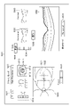
図1は、本発明の実施形態に係る撮影装置10の機能構成の一例を示すブロック図である。撮影装置10は、図1に示すように、光学系100、入力部200、全体制御部300、画像生成部400、表示制御部500、記憶部600、及び、表示部700の各機能構成部を有して構成されている。
[Overall configuration of photographing device 10]
FIG. 1 is a block diagram showing an example of the functional configuration of an imaging device 10 according to an embodiment of the invention. As shown in FIG. 1, the photographing apparatus 10 includes an optical system 100, an input unit 200, an overall control unit 300, an image generation unit 400, a display control unit 500, a storage unit 600, and a display unit 700. It is configured with

光学系100は、全体制御部300の制御に基づいて、測定対象Tに対して測定光を照射し、測定対象Tからの測定光の戻り光を検出等する構成部である。入力部200は、全体制御部300等に対して、各種の情報等を入力する構成部である。この入力部200は、例えば、ユーザーが操作入力を行えるキーボードやマウス等から構成されている。全体制御部300は、例えば入力部200から入力された情報等に基づいて、撮影装置10の動作を統括的に制御等する構成部である。画像生成部400は、全体制御部300の制御に基づいて、光学系100の出力である信号Sを処理して画像IMを生成する構成部である。表示制御部500は、例えば画像生成部400で生成された画像IMや入力部200から入力された情報等を表示部700に表示する制御を行う構成部である。なお、図1に示す例では、全体制御部300とは別構成で表示制御部500を設ける例について示しているが、例えば、表示制御部500の機能を全体制御部300の中に組み入れて全体制御部300が表示部700に対する表示制御を行う形態であってもよい。記憶部600は、全体制御部300、画像生成部400及び表示制御部500が各種の処理を行う際に必要なプログラムや各種の情報等を記憶している構成部である。また、記憶部600は、全体制御部300、画像生成部400及び表示制御部500が各種の処理を行うことによって取得した各種の情報等を記憶する構成部である。例えば、記憶部600は、画像生成部400で生成された画像IMとともに測定対象Tを特定する情報を記憶する。表示部700は、例えば、液晶ディスプレイ等の表示デバイスを含み構成されている構成部である。 The optical system 100 is a component that irradiates the measurement target T with measurement light and detects the return light of the measurement light from the measurement target T under the control of the overall control unit 300 . The input unit 200 is a component for inputting various information and the like to the general control unit 300 and the like. The input unit 200 is composed of, for example, a keyboard, a mouse, and the like with which the user can input operations. The overall control unit 300 is a component that controls the overall operation of the imaging device 10 based on, for example, information input from the input unit 200 . The image generator 400 is a component that processes the signal S output from the optical system 100 and generates an image IM under the control of the overall controller 300 . The display control unit 500 is a component that performs control for displaying, for example, an image IM generated by the image generation unit 400 and information input from the input unit 200 on the display unit 700 . Note that the example shown in FIG. 1 shows an example in which the display control unit 500 is provided separately from the overall control unit 300. The control unit 300 may be configured to perform display control on the display unit 700 . The storage unit 600 is a configuration unit that stores programs and various types of information necessary for the overall control unit 300, the image generation unit 400, and the display control unit 500 to perform various types of processing. Further, the storage unit 600 is a component that stores various kinds of information and the like acquired by various processes performed by the overall control unit 300, the image generation unit 400, and the display control unit 500. FIG. For example, the storage unit 600 stores information specifying the measurement target T together with the image IM generated by the image generation unit 400 . The display unit 700 is, for example, a component including a display device such as a liquid crystal display.

図2は、本発明の実施形態に係る撮影装置10の外観構成の一例を示す図である。この図2において、図1に示す構成と同様の構成については同じ符号を付しており、その詳細な説明は省略する。撮影装置10は、図2に示すように、光学ヘッド11、ステージ部12、ベース部13、PC(パーソナルコンピュータ)14、顔受け15、入力部200、及び、表示部700の各外観構成部を有して構成されている。また、図2には、3次元空間における位置を定めるためのXYZ座標系を示している。なお、図2に示す例は、図1に示す測定対象Tとして、被検者の眼(被検眼)Eを適用した例を示し、この場合、撮影装置10として眼科撮影装置を適用した例となる。 FIG. 2 is a diagram showing an example of the external configuration of the photographing device 10 according to the embodiment of the present invention. In FIG. 2, the same reference numerals are assigned to the same components as those shown in FIG. 1, and detailed description thereof will be omitted. As shown in FIG. 2, the photographing apparatus 10 includes an optical head 11, a stage section 12, a base section 13, a PC (personal computer) 14, a face support 15, an input section 200, and a display section 700. It is configured with FIG. 2 also shows an XYZ coordinate system for determining positions in a three-dimensional space. The example shown in FIG. 2 shows an example in which the subject's eye (eye to be examined) E is applied as the measurement target T shown in FIG. Become.

光学ヘッド11は、図1に示す光学系100を含む筐体である。ステージ部12は、例えば図1に示す全体制御部300の制御に基づいて、光学ヘッド11を、ベース部13に対してXYZ方向にモータ等により移動する構成部である。ベース部13は、ステージ部12を介して、光学ヘッド11を支持する構成部である。また、このベース部13は、顔受け15も支持する構成部となっている。顔受け15は、被検者の顔Fを固定するための構成部である。 The optical head 11 is a housing containing the optical system 100 shown in FIG. The stage unit 12 is a component that moves the optical head 11 in the XYZ directions with respect to the base unit 13 by a motor or the like, based on the control of the general control unit 300 shown in FIG. 1, for example. The base portion 13 is a component that supports the optical head 11 via the stage portion 12 . Further, the base portion 13 is a component that also supports the face support 15 . The face support 15 is a component for fixing the face F of the subject.

PC14は、図1に示す全体制御部300、画像生成部400、表示制御部500及び記憶部600を含み構成されたコンピュータである。PC14は、例えば、図1に示す全体制御部300、画像生成部400及び表示制御部500を、CPU等のハードウェアで実現可能なソフトウェアモジュールとして実現することができる。なお、以下に記載する本発明の実施形態では、PC14のCPU(不図示)が記憶部600に記憶されているプログラムを実行することによって当該ソフトウェアモジュールを実現する例について説明を行うが、本発明はこの形態に限定されるものではない。例えば、画像生成部400をASIC等の専用のハードウェアで実現してもよいし、表示制御部を当該CPUとは異なるGPU等の専用プロセッサーによって実現してもよい。また、光学ヘッド11内に設けられている光学系100とPC14との接続は、例えばネットワークを介した構成によって実現する形態も、本発明に適用可能である。 The PC 14 is a computer including the overall control unit 300, the image generation unit 400, the display control unit 500, and the storage unit 600 shown in FIG. The PC 14 can realize, for example, the overall control unit 300, the image generation unit 400, and the display control unit 500 shown in FIG. 1 as software modules that can be realized by hardware such as a CPU. In the embodiment of the present invention described below, an example in which the CPU (not shown) of the PC 14 executes a program stored in the storage unit 600 to implement the software module will be described. is not limited to this form. For example, the image generation unit 400 may be realized by dedicated hardware such as ASIC, and the display control unit may be realized by a dedicated processor such as GPU different from the CPU. Further, a configuration in which the connection between the optical system 100 provided in the optical head 11 and the PC 14 is realized by a configuration via a network, for example, is also applicable to the present invention.

次に、図1に示す各構成部の詳細について説明を行う。 Next, details of each component shown in FIG. 1 will be described.

<光学系100>
まず、図1に示す光学系100について説明する。
図3は、図1に示す光学系100の内部構成の一例を示す図である。なお、図3に示す例も、図2と同様に、図1に示す測定対象Tとして被検眼Eを適用した例を示す。
<Optical system 100>
First, the optical system 100 shown in FIG. 1 will be described.
FIG. 3 is a diagram showing an example of the internal configuration of the optical system 100 shown in FIG. Note that the example shown in FIG. 3 also shows an example in which the subject's eye E is applied as the measurement target T shown in FIG. 1, similarly to FIG.

光学系100は、光源101、光ファイバー102-1~102-3、カプラー103、コリメートレンズ104、ビームスプリッター105、アパーチャ107、接眼光学系140、参照光学系150、及び、受光光学系160を有して構成されている。なお、図3には、図示していないが、光学系100は、被検眼Eの眼底Erの撮影位置を確認するための広画角眼底撮影部、アライメントを容易にするための前眼部観察部、被検眼Eに固視位置を提示する固視灯光学系も更に有して構成されている。そして、これらの広画角眼底撮影部、前眼部観察部及び固視灯光学系は、本実施形態においては公知の構成を用いることができ、また、本発明の中心的な構成ではないため、その説明は省略する。 The optical system 100 has a light source 101, optical fibers 102-1 to 102-3, a coupler 103, a collimator lens 104, a beam splitter 105, an aperture 107, an eyepiece optical system 140, a reference optical system 150, and a light receiving optical system 160. configured as follows. Although not shown in FIG. 3, the optical system 100 includes a wide-angle fundus photographing unit for confirming the photographing position of the fundus Er of the eye E to be examined, and an anterior eye observation unit for facilitating alignment. A fixation lamp optical system for presenting the eye E to be examined with a fixation position is also provided. The wide-field-angle fundus photographing unit, the anterior segment observation unit, and the fixation lamp optical system can use known configurations in the present embodiment, and are not core configurations of the present invention. , the description of which is omitted.

光源101は、出力する光の波長を変更可能に構成された波長掃引光源(波長スキャン光源)である。この光源101は、全体制御部300の制御に基づき、例えば、1回のスキャンにおけるスキャンを開始する波長及び波長幅、さらに1秒当たりのスキャン回数であるスキャン速度等のパラメータを変更することが可能である。本実施形態では、毎秒25スキャンを標準スキャン速度としている。また、本実施形態では、予め、光源101の波長ごとの光強度データ(以下、「スペクトルデータ」と呼ぶ)が測定され、記憶部600に記憶されている。 The light source 101 is a wavelength swept light source (wavelength scanning light source) that can change the wavelength of light to be output. The light source 101 can change parameters such as the wavelength and wavelength width at which scanning is started in one scan, and the scan speed, which is the number of scans per second, under the control of the overall control unit 300. is. In this embodiment, the standard scanning speed is 25 scans per second. Further, in this embodiment, light intensity data for each wavelength of the light source 101 (hereinafter referred to as “spectrum data”) is measured in advance and stored in the storage unit 600 .

光源101から射出された光は、シングルモードの光ファイバー102-1を介して、カプラー103に入射する。カプラー103は、光源からの光を測定光121と参照光123とに分岐する光分岐手段である。そして、カプラー103で分岐された測定光121は、シングルモードの光ファイバー102-2を介して、コリメートレンズ104に導かれ、その後、アパーチャ107を介してビームスプリッター105に導かれる。また、カプラー103で分岐された参照光123は、シングルモードの光ファイバー102-3を介して、参照光学系150に導かれる。 Light emitted from the light source 101 enters the coupler 103 via the single-mode optical fiber 102-1. The coupler 103 is an optical splitter that splits the light from the light source into the measurement light 121 and the reference light 123 . The measurement light 121 split by the coupler 103 is guided to the collimator lens 104 via the single-mode optical fiber 102-2 and then guided to the beam splitter 105 via the aperture 107. FIG. Reference light 123 branched by coupler 103 is guided to reference optical system 150 via single-mode optical fiber 102-3.

アパーチャ107は、測定光121の強度分布が概略均一な領域を切り出すために設けられている。本実施形態においては、測定光121がガウシアン分布をしているため、ピーク強度の半分程度以上となる測定光121の領域がアパーチャ107を通過するように構成されている。さらに、本実施形態においては、アパーチャ107は、アパーチャ径が可変に構成されており、眼底Erを照射する領域を変更することが可能となっている。この構成により、被検眼Eが近視や遠視などの場合においても、被検眼Eが正視の場合と同様の照射領域となるように、全体制御部300が制御を行い得る。なお、アパーチャ107の制御は、フォーカス調整機構141と連動して行い得る。 Aperture 107 is provided to cut out a region where the intensity distribution of measurement light 121 is substantially uniform. In this embodiment, since the measurement light 121 has a Gaussian distribution, the aperture 107 is configured to pass through the area of the measurement light 121 where the peak intensity is about half or more. Furthermore, in the present embodiment, the aperture 107 is configured to have a variable aperture diameter, which makes it possible to change the irradiation area of the fundus Er. With this configuration, even when the subject's eye E is myopic or hyperopic, the overall control unit 300 can perform control so that the illumination region is the same as when the subject's eye E is emmetropic. Note that the control of the aperture 107 can be performed in conjunction with the focus adjustment mechanism 141 .

また、本実施形態においては、コリメートレンズ104の焦点距離は、アパーチャ107のアパーチャ径が最も大きくなる条件において測定光121の強度分布が概略均一となるように選択されている。なお、より高出力の光源101を使用することで、ピーク強度に対する強度の低下許容量を厳しくし、より均一な領域を選択して使用してもよい。 In this embodiment, the focal length of the collimator lens 104 is selected so that the intensity distribution of the measurement light 121 is approximately uniform under the condition that the aperture diameter of the aperture 107 is maximized. By using a higher output light source 101, the allowable decrease in intensity with respect to the peak intensity may be tightened, and a more uniform region may be selected and used.

測定光121は、ビームスプリッター105を透過した後、接眼光学系140に導かれる。具体的に、接眼光学系140に導かれた測定光121は、フォーカス調整機構141、スキャナ142、リレー光学系143、スキャナ144、接眼レンズ145及びアパーチャ146を介して、被検眼Eに導光され、眼底Erの2次元領域を照射する。ここで、本実施形態においては、接眼光学系140は、測定光121を測定対象Tである被検眼E(より詳細には、被検眼Eの眼底Er)の2次元領域に照射する照射手段である。 The measurement light 121 is guided to the eyepiece optical system 140 after passing through the beam splitter 105 . Specifically, the measurement light 121 guided to the eyepiece optical system 140 is guided to the subject's eye E via a focus adjustment mechanism 141, a scanner 142, a relay optical system 143, a scanner 144, an eyepiece lens 145, and an aperture 146. , irradiate a two-dimensional area of the fundus Er. Here, in the present embodiment, the eyepiece optical system 140 is irradiation means for irradiating a two-dimensional region of the eye to be examined E (more specifically, the fundus Er of the eye to be examined E), which is the measurement target T, with the measurement light 121. be.

被検眼Eの眼底Erで反射した測定光121は、測定光の戻り光122として、測定光121が辿った光路を逆順に辿る。具体的に、測定光の戻り光122は、接眼光学系140に入射して、アパーチャ146、接眼レンズ145、スキャナ144、リレー光学系143、スキャナ142及びフォーカス調整機構141を介して、ビームスプリッター105に導かれる。そして、ビームスプリッター105に導かれた戻り光122は、ビームスプリッター105を介して、受光光学系160に入射する。なお、図3では、戻り光122として、測定光121で照射した眼底Erの2次元領域のうちの一部で反射した光が2次元センサー162に結像されることを模式的に示しているが、実際には、本実施形態では、測定光121で照射した眼底Erの2次元領域で反射した戻り光122は全て2次元センサー162に結像するように構成されている。 The measuring light 121 reflected by the fundus Er of the eye to be examined E follows the optical path followed by the measuring light 121 in reverse order as return light 122 of the measuring light. Specifically, the return light 122 of the measurement light enters the eyepiece optical system 140, passes through the aperture 146, the eyepiece lens 145, the scanner 144, the relay optical system 143, the scanner 142, and the focus adjustment mechanism 141, and passes through the beam splitter 105. led to. The return light 122 guided to the beam splitter 105 enters the light receiving optical system 160 via the beam splitter 105 . Note that FIG. 3 schematically shows that light reflected by a part of the two-dimensional area of the fundus Er irradiated with the measurement light 121 is imaged on the two-dimensional sensor 162 as the return light 122 . Actually, however, in this embodiment, all the return light 122 reflected by the two-dimensional region of the fundus Er irradiated with the measurement light 121 is formed as an image on the two-dimensional sensor 162 .

フォーカス調整機構141は、ミラー141-1及び141-2、ステージ141-3、並びに、プリズム141-4を含み構成されており、眼底Erと2次元センサー162との結像関係を調整する機構である。光源101の側からフォーカス調整機構141に入射した測定光121は、プリズム141-4の一方の面で反射された後、ミラー141-1及びミラー141-2で順次反射され、プリズム141-4の他方の面で反射される。このミラー141-1及びミラー141-2は、図3に示すように、ステージ141-3に配置されている。例えば、全体制御部300が、入力部200からの入力等に基づき、ステージ141-3を図2の矢印に示す方向に動かすことで、測定光121の光路長を変更することができるようになっている。 The focus adjustment mechanism 141 includes mirrors 141-1 and 141-2, a stage 141-3, and a prism 141-4. be. The measurement light 121 incident on the focus adjustment mechanism 141 from the light source 101 side is reflected by one surface of the prism 141-4, then sequentially reflected by the mirrors 141-1 and 141-2. Reflected on the other side. The mirrors 141-1 and 141-2 are arranged on a stage 141-3 as shown in FIG. For example, the overall control unit 300 can change the optical path length of the measurement light 121 by moving the stage 141-3 in the direction indicated by the arrow in FIG. ing.

スキャナ142及びスキャナ144は、例えば、光を反射する反射面の角度が可変なガルバノスキャナである。このスキャナ142及びスキャナ144は、全体制御部300の制御によって、それぞれ、測定光121による眼底Erの照射位置を相互に直交するX方向(水平方向)及びY方向(垂直方向)の2方向に移動(ステアリング)することができる。また、このスキャナ142及びスキャナ144は、リレー光学系143及び接眼レンズ145により、被検眼Eの瞳Pと共役関係となるように配置されている。この構成により、全体制御部300は、スキャナ142及びスキャナ144によるステアリングに関わらず、被検眼Eに入射する測定光121が瞳Pの概略同じ領域を通過するように制御することができる。また、この制御により、測定光121が被検眼Eにおいて部分的に遮られることがなくなり、効率良くステアリングを行うことができる。 The scanner 142 and the scanner 144 are, for example, galvanometer scanners with variable angles of reflecting surfaces that reflect light. The scanner 142 and the scanner 144 are controlled by the overall control unit 300 to move the irradiation position of the measurement light 121 on the fundus Er in two mutually orthogonal X-direction (horizontal) and Y-direction (vertical) directions. (steering). Further, the scanner 142 and the scanner 144 are arranged so as to have a conjugate relationship with the pupil P of the subject's eye E by means of a relay optical system 143 and an eyepiece lens 145 . With this configuration, the overall control unit 300 can control the measurement light 121 incident on the subject's eye E to pass through approximately the same region of the pupil P regardless of steering by the scanner 142 and the scanner 144 . In addition, this control prevents the measurement light 121 from being partially blocked by the subject's eye E, so that efficient steering can be performed.

アパーチャ146は、測定光121の被検眼Eに近接した集光点の略近傍に配置されており、眼底Erを好適に照射できるように構成されている。 The aperture 146 is arranged substantially near the condensing point of the measuring light 121 close to the subject's eye E, and is configured to suitably irradiate the fundus Er.

一方、シングルモードの光ファイバー102-3から射出された参照光123は、上述したように、参照光学系150に導かれる。具体的に、参照光学系150に入射した参照光123は、コリメートレンズ151、アパーチャ153、分散補償ガラス154及び転送光学素子155に導かれる。その後、参照光123は、転送光学素子155を介して、ビームスプリッター105に導かれる。 On the other hand, the reference light 123 emitted from the single-mode optical fiber 102-3 is guided to the reference optical system 150 as described above. Specifically, the reference light 123 incident on the reference optical system 150 is guided to the collimator lens 151 , the aperture 153 , the dispersion compensating glass 154 and the transfer optical element 155 . Reference beam 123 is then directed to beam splitter 105 via transfer optics 155 .

分散補償ガラス154は、被検眼Eや光学系100を構成する光学素子による分散を補償するために用いられる。また、図3に示すように、光ファイバー102-3の射出端及びコリメートレンズ151は、ステージ152に配置されている。例えば、全体制御部300が、入力部200からの入力等に基づき、被検者の被検眼Eにおける眼軸長の相違等に対応してステージ152を光軸方向に駆動することで、コヒーレンスゲート位置を調整することができるようになっている。ここで、コヒーレンスゲート位置とは、測定光121と戻り光122の光路長に対する参照光123の光路長の差が無くなる位置を表す。なお、本実施形態では、参照光123の光路長を変更しているが、本発明においてはこの形態に限定されるものではなく、測定光121と戻り光122の光路長と参照光123の光路長との光路長差を変更できればよい。 The dispersion compensating glass 154 is used to compensate for dispersion due to the eye E to be examined and the optical elements forming the optical system 100 . Also, as shown in FIG. 3, the exit end of the optical fiber 102-3 and the collimator lens 151 are arranged on a stage 152. FIG. For example, the overall control unit 300 drives the stage 152 in the optical axis direction based on the input from the input unit 200 and the like in accordance with the difference in the axial length of the subject's eye E to be examined. The position can be adjusted. Here, the coherence gate position represents a position where the difference in the optical path length of the reference light 123 with respect to the optical path lengths of the measurement light 121 and the return light 122 disappears. In this embodiment, the optical path length of the reference light 123 is changed, but the present invention is not limited to this embodiment. It suffices if the difference in optical path length can be changed.

また、本実施形態では、ステージ152を動かすことによって光ファイバー102-3の射出端及びコリメートレンズ151を動かす構成としたが、本発明においてはこの形態に限定されるものではない。例えば、アパーチャ153の直前にオプトメータを配置する構成であってもよく、後述する縦トラッキングの動作速度を上げるため、重量の少ない素子をステージ152に搭載する構成を採用することが望ましい。 Further, in this embodiment, the exit end of the optical fiber 102-3 and the collimator lens 151 are moved by moving the stage 152, but the present invention is not limited to this form. For example, an optometer may be arranged immediately before the aperture 153, and it is desirable to adopt a configuration in which a light weight element is mounted on the stage 152 in order to increase the operating speed of longitudinal tracking, which will be described later.

ビームスプリッター105は、接眼光学系140から入射した戻り光122と参照光学系150から入射した参照光123とを合波して、干渉光124を生成する合波手段である。そして、ビームスプリッター105で生成された干渉光124は、受光光学系160に導かれる。 The beam splitter 105 is combining means for combining the return light 122 incident from the eyepiece optical system 140 and the reference light 123 incident from the reference optical system 150 to generate interference light 124 . Interference light 124 generated by beam splitter 105 is guided to light receiving optical system 160 .

受光光学系160に導かれた干渉光124は、結像光学系161を介して2次元センサー162で受光される。2次元センサー162は、入射した干渉光124を干渉信号として検出する検出手段である。そして、2次元センサー162は、検出した干渉信号のデータを内部メモリ163に蓄積する。ここで、2次元センサー162は、2次元状に配置された複数の受光素子(以下、この受光素子を「画素」と呼ぶ)を含み構成されており、各画素は、露光タイミングに従って入射した干渉光124を干渉信号に変換する。 The interference light 124 guided to the light receiving optical system 160 is received by the two-dimensional sensor 162 via the imaging optical system 161 . The two-dimensional sensor 162 is detection means for detecting the incident interference light 124 as an interference signal. Then, the two-dimensional sensor 162 accumulates the detected interference signal data in the internal memory 163 . Here, the two-dimensional sensor 162 includes a plurality of light-receiving elements arranged two-dimensionally (the light-receiving elements are hereinafter referred to as “pixels”). It converts the light 124 into an interference signal.

図4は、本発明の実施形態を示し、干渉画像、干渉信号及び断層信号の一例を示す図である。具体的に、図4(a)に干渉画像810の一例を示し、図4(b)に干渉信号820の一例を示し、図4(c)に断層信号830の一例を示している。 FIG. 4 shows an embodiment of the present invention, and is a diagram showing an example of an interference image, an interference signal, and a tomographic signal. Specifically, FIG. 4A shows an example of an interference image 810, FIG. 4B shows an example of an interference signal 820, and FIG. 4C shows an example of a tomographic signal 830. As shown in FIG.

図4(a)に示すように、2次元センサー162の1回の露光により生成される信号は、眼底Erの正面図に干渉縞が重畳した干渉画像810となる。また、図4(a)に示す干渉画像810の座標812は、2次元センサー162の各画素に対応しており、インデックスi=1,2,・・・,Nを用いて、(Xi,Yi)と表される。ここで、Nは、干渉画像810の総座標数であり、干渉画像810の左上が基準座標811(X1,Y1)となっている。 As shown in FIG. 4A, the signal generated by one exposure of the two-dimensional sensor 162 becomes an interference image 810 in which interference fringes are superimposed on the front view of the fundus Er. Coordinates 812 of the interference image 810 shown in FIG. 4(a) correspond to each pixel of the two-dimensional sensor 162, and using indices i=1, 2, . ). Here, N is the total number of coordinates of the interference image 810, and the upper left of the interference image 810 is the reference coordinate 811 (X1, Y1).

また、図4(a)に示す眼底画像である干渉画像810の座標812(Xi,Yi)における1回の波長スキャンの信号は、図4(b)に示す干渉信号820となる。また、この図4(b)に示す干渉信号820を演算処理することにより、図4(c)に示す断層信号830が得られ、複数の断層信号830から断層画像が生成される。ここで、図4(c)の横軸に示す断層方向は、被検眼E(より具体的に本実施形態では、被検眼Eの眼底Er)の深さ方向(Z方向)に相当する方向である。 The signal of one wavelength scan at the coordinates 812 (Xi, Yi) of the interference image 810, which is the fundus image shown in FIG. 4(a), becomes the interference signal 820 shown in FIG. 4(b). 4B, a tomographic signal 830 shown in FIG. 4C is obtained, and a tomographic image is generated from a plurality of tomographic signals 830. FIG. Here, the tomographic direction indicated by the horizontal axis in FIG. 4C is the direction corresponding to the depth direction (Z direction) of the subject's eye E (more specifically, in this embodiment, the fundus Er of the subject's eye E). be.

人眼は、固視微動等による揺れが存在するため、被検眼Eを完全に静止した状態で撮影を行うことは難しい。良好な画質の画像を得るためには、固視微動等の人眼の動きの影響を受けない撮影速度にすることが望ましく、例えば、2次元センサー162によって毎秒4000フレーム以上の撮影速度で撮影を行うことが好ましい。 Since the human eye fluctuates due to involuntary eye movement or the like, it is difficult to photograph the subject's eye E in a completely stationary state. In order to obtain an image of good quality, it is desirable to set the shooting speed to be unaffected by the movement of the human eye such as involuntary eye movement. preferably.

なお、図5を用いて後述するプレビュー領域922におけるユーザーの指定等に基づき、図4(a)に示す干渉画像810の部分領域813のデータが画像生成部400にリアルタイムに送られ画像化される。この画像は、さらに、表示部700にリアルタイムに表示される。この構成により膨大なデータ転送が不要となり、ユーザーにリアルタイムにプレビュー画像を提示することができる。また、ユーザーは、このプレビュー画像に基づき、フォーカスや、コヒーレンスゲート位置あるいは上述したステアリングにおいて、コヒーレンスゲート位置等が適切か否かを判断することが可能である。 Data of a partial area 813 of the interference image 810 shown in FIG. 4A is sent to the image generation unit 400 in real time and imaged based on user's designation in the preview area 922, which will be described later with reference to FIG. . This image is further displayed on the display unit 700 in real time. This configuration eliminates the need to transfer a large amount of data, and can present a preview image to the user in real time. Also, based on this preview image, the user can determine whether the coherence gate position or the like is appropriate in terms of focus, coherence gate position, or steering described above.

なお、本実施形態においては、コリメートレンズ151とアパーチャ153を適切に選択することにより、参照光123は、2次元センサー162上で、測定光121よりも広い領域に結像される構成となっている。この構成により、光学系の調整に求められる精度が緩和され、より安定して撮影を行うことが可能である。 In this embodiment, by appropriately selecting the collimating lens 151 and the aperture 153, the reference light 123 is imaged in a wider area than the measurement light 121 on the two-dimensional sensor 162. there is With this configuration, the accuracy required for adjusting the optical system is relaxed, and more stable imaging can be performed.

<全体制御部300>
次に、図1に示す全体制御部300について説明する。
本実施形態においては、全体制御部300は、上述したように、PC14のCPUによって実現されるソフトウェアモジュールとして構成されており、図3に示す光学系100の各構成部を制御する。さらに、本実施形態においては、全体制御部300は、撮影装置10の全体の動作を制御するとともに、各種の選択処理や各種の計測処理、各種の演算処理を行う手段としても機能する。また、全体制御部300は、撮影装置10を操作するユーザーの入力を入力部200を介して受け付けるものとする。具体的に、例えば、全体制御部300には、入力部200を介して、被検眼Eを特定する患者ID等の情報、撮影に必要なパラメータ、眼底Erをスキャンするパターンの選択等が入力される。そして、全体制御部300は、この入力部200を介して入力された各種の情報に基づいて、撮影装置10の各構成部を制御するとともに、得られた信号、画像等のデータを記憶部600に保存する機能を有する。
<Overall Control Unit 300>
Next, the overall control unit 300 shown in FIG. 1 will be described.
In this embodiment, as described above, the overall control unit 300 is configured as a software module realized by the CPU of the PC 14, and controls each component of the optical system 100 shown in FIG. Furthermore, in the present embodiment, the overall control unit 300 controls the overall operation of the photographing apparatus 10 and also functions as means for performing various selection processes, various measurement processes, and various arithmetic processes. Also, the overall control unit 300 receives input from the user who operates the photographing device 10 via the input unit 200 . Specifically, for example, the overall control unit 300 receives, via the input unit 200, information such as a patient ID that identifies the eye E to be examined, parameters necessary for imaging, selection of a pattern for scanning the fundus Er, and the like. be. The overall control unit 300 controls each component of the photographing apparatus 10 based on various types of information input via the input unit 200, and stores data such as obtained signals and images in the storage unit 600. It has the function of saving to

<画像生成部400>
次に、図1に示す画像生成部400について説明する。
画像生成部400は、光学系100から出力された信号Sに対して様々な処理を行うことによって、被検眼Eに関する画像を生成し出力する。
<Image generator 400>
Next, the image generator 400 shown in FIG. 1 will be described.
The image generator 400 performs various processes on the signal S output from the optical system 100 to generate and output an image of the subject's eye E. FIG.

<表示制御部500>
次に、図1に示す表示制御部500について説明する。
表示制御部500は、上述したように、全体制御部300の制御に基づいて、画像生成部400から取得した画像を表示部700に表示する制御を行う。
<Display control unit 500>
Next, the display control unit 500 shown in FIG. 1 will be described.
As described above, the display control unit 500 performs control to display the image acquired from the image generation unit 400 on the display unit 700 under the control of the overall control unit 300 .

図5は、本発明の実施形態を示し、図1に示す表示部700に表示される表示画面900の一例を示す図である。なお、この図5に示す表示画面900とは別に、全体制御部300によって入力される患者ID等の被検眼Eの特定情報の入力画面も表示部700に表示されうるが、この入力画面は、公知の構成を用いることができ、また、本発明の中心的な構成ではないため、その説明は省略する。 FIG. 5 shows an embodiment of the present invention, and is a diagram showing an example of a display screen 900 displayed on the display unit 700 shown in FIG. Note that, apart from the display screen 900 shown in FIG. 5, an input screen for specific information of the subject's eye E such as the patient ID input by the overall control unit 300 can also be displayed on the display unit 700. This input screen is A known configuration can be used, and since it is not the core configuration of the present invention, the description thereof will be omitted.

図5に示す表示画面900には、画像の表示領域910,920,930,940及び950、並びに、ユーザーが操作可能なユーザーインタフェース901~908が設けられている。具体的に、ユーザーが操作可能なユーザーインタフェースとして、左右眼の切り替えボタン901、アライメント調整部902、フォーカス調整スライダーバー903、コヒーレンスゲート調整スライダーバー904、コヒーレンスゲート自動調整ボタン905、表示モードプルダウンメニュー906、スキャンモードプルダウンメニュー907、及び、撮影ボタン908が設けられている。また、表示領域910,920,930,940及び950に表示される各画像は、画像生成部400で生成される。 A display screen 900 shown in FIG. 5 is provided with image display areas 910, 920, 930, 940 and 950, and user interfaces 901 to 908 that can be operated by the user. Specifically, as a user interface that can be operated by the user, a left/right eye switching button 901 , an alignment adjustment section 902 , a focus adjustment slider bar 903 , a coherence gate adjustment slider bar 904 , a coherence gate automatic adjustment button 905 , and a display mode pull-down menu 906 . , a scan mode pull-down menu 907, and a shooting button 908 are provided. Images displayed in the display areas 910 , 920 , 930 , 940 and 950 are generated by the image generator 400 .

表示領域910には、被検眼Eの前眼部画像が表示され、光学ヘッド11と被検眼Eとのアライメントを確認することができるようになっている。また、全体制御部300が測定光121の角膜での散乱光を自動で検出し、これを表示領域910の前眼部画像上に輝点911として強調表示させることで、測定光121が被検眼Eに入射する瞳孔における位置をユーザーが容易に視認できるようになっている。また、表示領域910には、被検眼Eの瞳孔の目標位置を提示する目標円912が前眼部画像上に重畳表示されており、アライメントが適切かどうかをユーザーが容易に判断できるようになっている。さらに、表示領域910には、マーク913が前眼部画像上に重畳表示されており、輝点911がマーク913と重なるようにアライメントすることで、角膜反射の写り込みの少ない眼底画像を取得することができるようになっている。また、被検眼Eの瞳孔中心からの距離を表示領域910の前眼部画像上に重畳表示し、測定光121の入射位置をユーザーが容易に把握できるようにしてもよい。なお、本実施形態の光学系100は、前眼部観察部と測定光121とを分離するダイクロイックミラー(不図示)の反射率を適切に選択し、表示領域910に表示される角膜の反射光の輝度値が飽和しないように構成されている。 An image of the anterior segment of the eye E to be examined is displayed in the display area 910 so that the alignment between the optical head 11 and the eye E to be examined can be confirmed. Further, the overall control unit 300 automatically detects scattered light from the cornea of the measurement light 121 and highlights it as a bright spot 911 on the anterior segment image of the display area 910, so that the measurement light 121 can The user can easily visually recognize the position in the pupil where E is incident. In addition, in the display area 910, a target circle 912 presenting the target position of the pupil of the subject's eye E is superimposed on the anterior segment image, allowing the user to easily determine whether the alignment is appropriate. ing. Furthermore, in the display area 910, a mark 913 is displayed superimposed on the anterior segment image, and by aligning the bright spot 911 so as to overlap the mark 913, a fundus image with little reflection of corneal reflection is obtained. It is possible to do so. Further, the distance from the center of the pupil of the subject's eye E may be superimposed on the anterior segment image in the display area 910 so that the user can easily grasp the incident position of the measurement light 121 . Note that the optical system 100 of the present embodiment appropriately selects the reflectance of a dichroic mirror (not shown) that separates the anterior segment observation part and the measurement light 121, and the reflected light from the cornea displayed in the display area 910 is is configured so that the luminance value of is not saturated.

表示領域920には、被検眼Eの眼底Erにおける広域の眼底平面画像がリアルタイムに表示され、また、この眼底平面画像上には断層画像の撮影領域921及びプレビュー領域922が重畳表示されている。 A wide-area fundus plane image of the fundus Er of the subject's eye E is displayed in real time in the display area 920, and a tomographic image capturing area 921 and a preview area 922 are superimposed on the fundus plane image.

撮影領域921は、ユーザーが入力部200を用いて指定する、断層画像を撮影する対象となる領域である。また、プレビュー領域922は、表示領域930及び940に、対応するそれぞれの矢印に示す方向の断層画像をプレビュー表示する位置を指定するものであり、ユーザーが入力部200を用いて指定する。 An imaging region 921 is a target region for imaging a tomographic image, specified by the user using the input unit 200 . Also, the preview area 922 designates the position for previewing the tomographic images in the directions indicated by the corresponding arrows in the display areas 930 and 940 , and is designated by the user using the input unit 200 .

以下、撮影領域921で指定される領域に基づき取得される一連の干渉画像をボリュームデータと呼ぶ。また、1回の波長スキャンで取得される一連の干渉画像を単一ボリュームデータと呼ぶ。この際、ボリュームデータは、複数の単一ボリュームから生成される。なお、以下では、ボリュームデータを取得することを撮影と呼び、単一ボリュームデータを取得することを単一撮影と呼ぶ。 A series of interference images acquired based on the area designated by the imaging area 921 is hereinafter referred to as volume data. A series of interference images obtained by one wavelength scan is called single volume data. At this time, volume data is generated from a plurality of single volumes. In the following description, acquisition of volume data will be referred to as imaging, and acquisition of single volume data will be referred to as single imaging.

撮影領域921とプレビュー領域922は、連動して動かすことも独立に動かすこともでき、また、不図示のスイッチにより連動と独立の動作を切り替えることが可能である。また、プレビュー領域922は、測定光121が眼底Erを照射する領域(2次元領域)に連動して自動で大きさが変わり、ステアリングを行わない単一撮影でデータが取得できる範囲をユーザーが容易に判別できるようになっている。 The photographing area 921 and the preview area 922 can be moved together or independently, and can be switched between combined and independent operations by a switch (not shown). In addition, the size of the preview area 922 is automatically changed in conjunction with the area (two-dimensional area) where the measurement light 121 irradiates the fundus Er, and the user can easily determine the range in which data can be acquired in a single shot without steering. can be discriminated.

表示モードプルダウンメニュー906は、表示領域950に表示する断層画像の種類を選択することができるものである。例えば、表示モードプルダウンメニュー906によって、撮影領域921で指定した領域の水平方向や鉛直方向の断層画像の他、3次元断層画像を選択することができる。 A display mode pull-down menu 906 allows selection of the type of tomographic image to be displayed in the display area 950 . For example, the display mode pull-down menu 906 allows selection of a three-dimensional tomographic image as well as horizontal and vertical tomographic images of the region specified by the imaging region 921 .

表示領域950に断層画像が表示された場合には、表示領域920の眼底平面画像上に重畳して表示されている十字線を動かすことにより、表示する断層画像の位置を変更することが可能である。本実施形態では、単一ボリュームデータから計算される水平方向(Horizontal)の断層画像が表示領域930に表示され、垂直方向(Vertical)の断層画像が表示領域940に表示される。さらに、プレビュー領域922には、矢印が重畳表示されており、断層画像の取得データの方向が容易に判別できるようになっている。さらに、本実施形態では、断層画像の移動や、拡大/縮小、コントラストの調整等を行うことが可能である。 When a tomographic image is displayed in the display area 950, the position of the tomographic image to be displayed can be changed by moving the crosshairs superimposed and displayed on the fundus plane image in the display area 920. be. In this embodiment, a horizontal tomographic image calculated from single volume data is displayed in the display area 930 , and a vertical tomographic image is displayed in the display area 940 . Furthermore, an arrow is superimposed on the preview area 922 so that the direction of the acquired data of the tomographic image can be easily determined. Furthermore, in this embodiment, it is possible to move the tomographic image, enlarge/reduce the image, adjust the contrast, and the like.

また、表示領域950に3次元断層画像が表示された場合には、入力部200を操作することにより、表示領域950上で3次元断層画像の移動や、回転、拡大/縮小、コントラストの調整が行える他、被検眼Eの眼底Erにおける特定の網膜層のみを表示することも可能である。 Further, when a three-dimensional tomographic image is displayed in the display area 950, by operating the input unit 200, the three-dimensional tomographic image can be moved, rotated, enlarged/reduced, and contrast can be adjusted on the display area 950. Besides, it is also possible to display only a specific retinal layer in the fundus Er of the eye E to be examined.

なお、ここでは、ユーザーからの指示によって表示する画像を変更する場合について説明を行ったが、例えば、診断したい疾病を不図示のメニューから選択(疾病名を選択)することにより、疾病に対して予め優先順位付けられた画像を表示するようにしてもよい。 Here, the case where the displayed image is changed according to an instruction from the user has been described. Pre-prioritized images may be displayed.

この図5に示す表示画面900を用いることによって、画像生成部400で生成される各画像をユーザーに効率よく提示することができる。また、ユーザーが必要とする画像を簡単な操作で選択することができる。さらに、例えば予め疾病名と表示する画像を対応付けておくことで更に操作が簡単となる。 By using the display screen 900 shown in FIG. 5, each image generated by the image generation unit 400 can be efficiently presented to the user. In addition, the user can select the desired image with a simple operation. Furthermore, for example, the operation is further simplified by associating the name of the disease with the image to be displayed in advance.

[撮影装置10の制御方法(撮影方法)]
図6は、本発明の実施形態に係る撮影装置10の撮影方法における処理手順の一例を示すフローチャートである。なお、図6には記載していないが、広画角眼底撮影部による眼底Erの広画角眼底画像の取得が図6に示すフローチャートの処理に先立ち開始され、所定のフレームレートで取得された広画角眼底画像がリアルタイムに表示領域920に表示される。
[Method for controlling photographing device 10 (imaging method)]
FIG. 6 is a flow chart showing an example of the processing procedure in the imaging method of the imaging device 10 according to the embodiment of the present invention. Although not shown in FIG. 6, acquisition of a wide-angle fundus image of the fundus Er by the wide-angle fundus imaging unit was started prior to the processing of the flowchart shown in FIG. 6, and was acquired at a predetermined frame rate. A wide-angle fundus image is displayed in the display area 920 in real time.

<ステップS101(左右眼の選択)>
顔受け15に被検者の顔Fが固定された状態で、ユーザーが左右眼の切り替えボタン901を押下すると、全体制御部300は、左右眼の切り替えボタン901に操作に基づき、撮影対象の被検眼Eとして右眼(R)または左眼(L)の選択を行う。その後、全体制御部300は、この左右眼の選択に基づき、予め記憶部600に記憶されていたデータを用いて光学ヘッド11を移動させる。なお、この際、全体制御部300は、前眼部観察部の取得データ等を用いて移動量を算出し、より精度良く光学ヘッド11を移動させてもよい。
<Step S101 (selection of left and right eyes)>
When the user presses the left/right eye switching button 901 while the subject's face F is fixed on the face support 15, the overall control unit 300 changes the subject to be photographed based on the operation of the left/right eye switching button 901. Right eye (R) or left eye (L) is selected as eye examination E. After that, the overall control unit 300 moves the optical head 11 using the data stored in advance in the storage unit 600 based on the selection of left and right eyes. At this time, the overall control unit 300 may calculate the amount of movement using the data acquired by the anterior segment observation unit and the like, and move the optical head 11 more accurately.

<ステップS102(撮影モードの選択)>
続いて、ユーザーがスキャンモードプルダウンメニュー907から撮影モードを指定すると、全体制御部300は、当該指定に基づき撮影モードを選択する。ここで、撮影モードとしては、例えば、標準スキャン速度で撮影を行う標準撮影モード(Standard Mode)や、網膜Erの断層方向の分解能を向上させた高分解能モード(High Resolution Mode)、標準スキャン速度よりも速く撮影を行う高速撮影モード(High Speed Mode)等を選択することができる。
<Step S102 (selection of shooting mode)>
Subsequently, when the user specifies a shooting mode from the scan mode pull-down menu 907, the overall control unit 300 selects the shooting mode based on the specification. Here, the imaging modes include, for example, a standard imaging mode in which imaging is performed at a standard scanning speed, a high resolution mode in which the resolution in the tomographic direction of the retina Er is improved, and a standard scanning speed. It is possible to select a high-speed photographing mode (High Speed Mode) or the like in which photographing is performed as quickly as possible.

なお、本実施形態では、ユーザーが撮影モードを指定するものとしたが、診断したい疾病を不図示のメニューから選択(疾病名を選択)することにより、疾病に対して予め優先順位付けられたパラメータで撮影するようにしてもよい。 In the present embodiment, the user designates the imaging mode. However, by selecting a disease to be diagnosed from a menu (not shown) (selecting the name of the disease), the user can select parameter parameters that are prioritized in advance for the disease. You can shoot with .

<ステップS103(光源の波長掃引開始)>
続いて、全体制御部300は、光源101を点灯し、光源101から出力する光の波長掃引(波長スキャン)を開始する。具体的に、全体制御部300は、ステップS102で選択した撮影モードに基づき、予め記憶部600に記憶されている光源101のスキャン速度や、2次元センサー162の撮影領域(ROI)等のパラメータを用いて、光源101から出力する光の波長スキャンを開始する。
<Step S103 (start of wavelength sweep of light source)>
Subsequently, the overall control unit 300 turns on the light source 101 and starts wavelength sweeping (wavelength scanning) of the light output from the light source 101 . Specifically, based on the imaging mode selected in step S102, the overall control unit 300 sets parameters such as the scanning speed of the light source 101 and the imaging region (ROI) of the two-dimensional sensor 162, which are stored in advance in the storage unit 600. is used to initiate a wavelength scan of the light output from the light source 101 .

また、全体制御部300は、プレビュー領域922に基づいて部分領域813のデータを取得し、画像生成部400が画像化した画像を表示領域930及び940に表示させる。 Further, the overall control unit 300 acquires data of the partial area 813 based on the preview area 922 and causes the images generated by the image generation unit 400 to be displayed in the display areas 930 and 940 .

<ステップS104(アライメント調整)>
続いて、ユーザーが入力部200を介して表示領域910に表示された前眼部画像の瞳孔中心をクリックすると、全体制御部300は、当該クリックの位置に基づき、瞳孔中心が適切にアライメントされるように光学ヘッド11を移動させる。このとき、全体制御部300は、測定光121の入射位置が角膜頂点からずれるように制御を行い、被検眼Eの角膜による測定光121の反射光が2次元センサー162に到達しないように自動で調整する。
<Step S104 (alignment adjustment)>
Subsequently, when the user clicks the center of the pupil of the anterior segment image displayed in the display area 910 via the input unit 200, the overall control unit 300 appropriately aligns the center of the pupil based on the position of the click. The optical head 11 is moved as shown. At this time, the overall control unit 300 performs control so that the incident position of the measuring light 121 is shifted from the corneal vertex, and automatically prevents the reflected light of the measuring light 121 from the cornea of the eye to be examined E from reaching the two-dimensional sensor 162 . adjust.

また、ユーザーは、入力部200を介してアライメント調整部902のボタンをクリックすることで、アライメントの微調整を行うことができる。また、表示領域910には、上述したように、瞳孔の目標位置を提示する目標円912が前眼部画像上に重畳表示されており、アライメントが適切かどうかをユーザーが容易に判断できるようになっている。さらに、表示領域910には、上述したように、マーク913が前眼部画像上に重畳表示されており、輝点911がマーク913と重なるようにアライメントすることで、角膜反射の写り込みの少ない眼底画像を取得することができるようになっている。このマーク913は、記憶部600に記憶されたパラメータに基づく位置に表示されており、不図示のスイッチで表示と非表示を切り替えることが可能となっている。 Further, the user can perform fine alignment adjustment by clicking the button of the alignment adjustment section 902 via the input section 200 . Further, in the display area 910, as described above, the target circle 912 presenting the target position of the pupil is displayed superimposed on the anterior segment image so that the user can easily determine whether the alignment is appropriate. It's becoming Furthermore, in the display area 910, the mark 913 is superimposed on the anterior segment image as described above, and by aligning the bright spot 911 so as to overlap the mark 913, the corneal reflection is less reflected. A fundus image can be acquired. The mark 913 is displayed at a position based on the parameters stored in the storage unit 600, and can be switched between display and non-display with a switch (not shown).

<ステップS105(フォーカス調整)>
続いて、ユーザーが表示領域920に表示される広画角眼底画像を参照しながらフォーカス調整スライダーバー903を操作すると、全体制御部300は、ユーザーの操作入力値に基づき、広画角眼底撮影部のフォーカスを調整する。さらに、全体制御部300は、広画角眼底撮影部のフォーカス調整に連動して、フォーカス調整機構141を駆動する。
<Step S105 (focus adjustment)>
Subsequently, when the user operates the focus adjustment slider bar 903 while referring to the wide-angle fundus image displayed in the display area 920, the overall control unit 300 controls the wide-angle fundus imaging unit based on the user's operation input value. adjust the focus of Furthermore, the overall control unit 300 drives the focus adjustment mechanism 141 in conjunction with the focus adjustment of the wide-angle fundus imaging unit.

さらに、全体制御部300は、フォーカス調整機構141の動きに連動して、アパーチャ107のアパーチャ径の調整を行う。例えば、被検眼Eが近視眼の場合、眼底Erの照射領域が狭まるため、この場合、アパーチャ107のアパーチャ径が大きくなるように調整を行う。また、全体制御部300は、このアパーチャ107のアパーチャ径に連動して、被検眼Eへの入射光量が概略一定となるように光源101を制御する。本実施形態においては、フォーカス調整機構141とアパーチャ107との連動は、予め記憶部600に記憶されたパラメータに基づき行われる。 Furthermore, the overall control unit 300 adjusts the aperture diameter of the aperture 107 in conjunction with the movement of the focus adjustment mechanism 141 . For example, when the subject's eye E is myopic, the irradiation area of the fundus Er is narrowed. In this case, the aperture diameter of the aperture 107 is adjusted to be large. In addition, the overall control unit 300 controls the light source 101 in conjunction with the aperture diameter of the aperture 107 so that the amount of light incident on the subject's eye E is approximately constant. In this embodiment, the interlocking between the focus adjustment mechanism 141 and the aperture 107 is performed based on parameters stored in advance in the storage unit 600 .

なお、本実施形態においては、アパーチャ107のアパーチャ径は、手動で調整することも可能な構成となっており、被検眼Eの縮瞳等の条件によって眼底Erの照射領域を変更し、より効率的に撮影を行うことが可能となっている。 In the present embodiment, the aperture diameter of the aperture 107 can be manually adjusted, and the irradiation area of the fundus Er can be changed according to the conditions such as miosis of the eye E to be examined to improve the efficiency. It is possible to take pictures in real time.

アパーチャ107のアパーチャ径の調整が自動/手動のいずれの場合においても、プレビュー領域922の大きさは測定光121が眼底Erを照射する領域に連動して表示されるため、ユーザーは単一撮影での撮影範囲を容易に視認することが可能である。 Regardless of whether the aperture diameter of the aperture 107 is adjusted automatically or manually, the size of the preview area 922 is displayed in conjunction with the area where the measurement light 121 irradiates the fundus Er. It is possible to easily visually recognize the shooting range of .

なお、フォーカス調整機構141は、光路長を変化させるため、後述するステップS107で実施されるコヒーレンスゲート調整よりも先にフォーカスを調整することで調整が容易となる。また、本ステップとは異なるタイミングでフォーカスが調整された場合、コヒーレンスゲートを連動して調整することが望ましい。 Note that since the focus adjustment mechanism 141 changes the optical path length, adjustment is facilitated by adjusting the focus prior to the coherence gate adjustment performed in step S107, which will be described later. Also, if the focus is adjusted at a timing different from this step, it is desirable to adjust the coherence gate in conjunction with it.

<ステップS106(撮影位置選択)>
続いて、ユーザーが入力部200を介して所望のプレビュー位置となるよう指定を行うと、全体制御部300は、当該指定に基づきプレビュー領域922の位置の調整を行う。
<Step S106 (selection of shooting position)>
Subsequently, when the user designates a desired preview position via the input unit 200, the overall control unit 300 adjusts the position of the preview area 922 based on the designation.

<ステップS107(コヒーレンスゲート調整)>
続いて、ユーザーがコヒーレンスゲート自動調整ボタン905を押下すると、全体制御部300は、画像の輝度値に基づいてコヒーレンスゲート位置を判断し、ステージ152を駆動する。
<Step S107 (coherence gate adjustment)>
Subsequently, when the user presses the coherence gate automatic adjustment button 905 , the general control section 300 determines the coherence gate position based on the brightness value of the image and drives the stage 152 .

さらに、ユーザーは、入力部200を用いてコヒーレンスゲート調整スライダーバー904をスライドさせることで、コヒーレンスゲートの微調整を行うことができる。 Furthermore, the user can finely adjust the coherence gate by sliding the coherence gate adjustment slider bar 904 using the input unit 200 .

<ステップS108(撮影領域調整)>
続いて、ユーザーが、表示領域930及び940に表示の画像を確認しながら、入力部200から所望の撮影範囲となるように撮影領域921の位置と大きさ及びプレビュー領域922の位置の指定を行うと、全体制御部300は、当該指定に基づく調整を行う。
<Step S108 (shooting area adjustment)>
Subsequently, while confirming the images displayed in the display areas 930 and 940, the user designates the position and size of the photographing area 921 and the position of the preview area 922 from the input unit 200 so that the desired photographing range is obtained. Then, the overall control unit 300 performs adjustment based on the designation.

<ステップS109(撮影開始)>
続いて、ユーザーが撮影ボタン908を押下すると、全体制御部300は、撮影領域921に基づき、被検眼Eの断層画像の撮影等を開始する。撮影領域921がプレビュー領域922よりも狭く指定されている場合、全体制御部300は、撮影領域921とプレビュー領域922の中心が一致するようにステアリングし、単一撮影を行って単一ボリュームデータを取得する。また、撮影領域921がプレビュー領域922よりも広く指定されている場合、全体制御部300は、撮影領域921におけるボリュームデータが取得できるように、撮影順序を自動で判断する。
<Step S109 (start of shooting)>
Subsequently, when the user presses an imaging button 908 , the overall control unit 300 starts imaging a tomographic image of the subject's eye E based on the imaging region 921 . If the imaging area 921 is specified to be narrower than the preview area 922, the overall control unit 300 steers so that the centers of the imaging area 921 and the preview area 922 are aligned, performs single imaging, and generates single volume data. get. Also, if the shooting area 921 is specified to be wider than the preview area 922, the overall control unit 300 automatically determines the shooting order so that the volume data in the shooting area 921 can be acquired.

図7は、本発明の実施形態を示し、ボリュームデータの取得方法を説明するための図である。この図7において、図5に示す構成と同様の構成については同じ符号を付している。 FIG. 7 shows an embodiment of the present invention and is a diagram for explaining a volume data acquisition method. In FIG. 7, the same reference numerals are assigned to the same configurations as those shown in FIG.

全体制御部300は、ステップS109の撮影開始後、例えば図7(a)に示すように、プレビュー領域922を非表示とし、撮影領域921におけるボリュームデータが取得されるように自動でステアリングと単一撮影を交互に繰り返す。ここで、ステアリングは、上述したように、全体制御部300の制御によって、スキャナ142及びスキャナ144が、それぞれ、測定光121による眼底Erの照射位置をX方向(水平方向)及びY方向(垂直方向)の2方向に移動することである。この際、全体制御部300は、記憶部600に予め記憶されているパラメータに基づき、ステアリングの移動量や単一ボリュームデータ間の重なり合いの量を設定し、撮影領域921を包含するように制御する。ここで、包含するとは、得られるボリュームデータが撮影領域921で指定される領域よりも広いことを意味する。このため、ユーザーが意図した領域を確実に撮影することが可能である。本実施形態においては、単一撮影を行う際のステアリング量等のパラメータは、単一ボリュームデータと関連付けられて記憶部600に記憶されている。 After the start of imaging in step S109, the overall control unit 300 hides the preview area 922, for example, as shown in FIG. Take pictures alternately. Here, as described above, the steering is controlled by the overall control unit 300 so that the scanner 142 and the scanner 144 move the irradiation position of the measurement light 121 on the fundus Er in the X direction (horizontal direction) and the Y direction (vertical direction). ) in two directions. At this time, the overall control unit 300 sets the amount of steering movement and the amount of overlap between single volume data based on parameters stored in advance in the storage unit 600, and performs control so that the imaging region 921 is included. . Here, including means that the obtained volume data is wider than the area designated by the imaging area 921 . Therefore, it is possible to reliably photograph the area intended by the user. In this embodiment, the parameters such as the amount of steering for single imaging are stored in the storage unit 600 in association with the single volume data.

さらに、全体制御部300は、撮影ボタン908が押下された直後、撮影領域921の概略中央の単一撮影を行い、部分領域813における断層画像をリファレンス断層画像として記憶部600に記憶する。以降の単一撮影では、全体制御部300は、既に撮影した単一ボリュームデータに隣接するように順次単一撮影を行う。また、全体制御部300は、部分領域813の断層画像をリファレンス断層画像と比較した結果に基づいて、次の隣接する撮影位置へステアリングする前に自動で、フォーカスとコヒーレンスゲート位置を調整する。また、全体制御部300は、フォーカスまたはコヒーレンスゲート位置が大幅にずれていると判断した場合、フォーカスまたはコヒーレンスゲート位置を調整して再撮影を行うように構成してもよい。この構成により、常に最適なフォーカス及びコヒーレンスゲート位置での単一撮影を行うことが可能となる。 Furthermore, immediately after the imaging button 908 is pressed, the overall control unit 300 performs single imaging of the approximate center of the imaging region 921, and stores the tomographic image in the partial region 813 in the storage unit 600 as a reference tomographic image. In subsequent single imaging, the overall control unit 300 sequentially performs single imaging so as to be adjacent to the already captured single volume data. Also, based on the result of comparing the tomographic image of the partial region 813 with the reference tomographic image, the overall control unit 300 automatically adjusts the focus and coherence gate position before steering to the next adjacent imaging position. Further, the overall control unit 300 may be configured to adjust the focus or coherence gate position and perform re-shooting when determining that the focus or coherence gate position has shifted significantly. With this configuration, it is possible to always perform single imaging at the optimum focus and coherence gate positions.

なお、図7(a)では、アパーチャ107のアパーチャ形状が矩形である場合を示したが、例えば、図7(b)に示すように、アパーチャ107のアパーチャ形状が円形である場合にも、同様の撮影手順が適用可能である。即ち、全体制御部300は、記憶部600に予め記憶されたパラメータに基づいて、ステアリングの移動量や単一ボリュームデータ間の重なり合いの量を設定し、撮影領域921を包含するように制御する。 Although FIG. 7A shows the case where the aperture shape of the aperture 107 is rectangular, for example, as shown in FIG. 7B, the aperture shape of the aperture 107 is also circular. is applicable. That is, the overall control unit 300 sets the amount of steering movement and the amount of overlap between single volume data based on parameters stored in advance in the storage unit 600, and controls to include the imaging region 921. FIG.

なお、図7(a)に示すアパーチャ形状が矩形の場合、撮影時のステアリングの移動量や単一ボリューム間の重なり合いの量が容易に設定できる。一方、図7(b)に示すアパーチャ形状が円形の場合、シングルモードの光ファイバー102-2から射出するガウシアンビームを有効に利用することが可能である。 If the shape of the aperture shown in FIG. 7A is rectangular, it is possible to easily set the amount of movement of the steering wheel and the amount of overlap between the single volumes during photographing. On the other hand, when the aperture shape shown in FIG. 7B is circular, it is possible to effectively use the Gaussian beam emitted from the single-mode optical fiber 102-2.

また、図7(a)及び図7(b)では、単一撮影が終了した領域を撮影済み領域923として示している。この撮影済み領域923は、例えば、表示領域920において半透明のカラーで表示され、ユーザーが単一撮影済みの領域かどうかを容易に判断することができるようになっている。 In addition, in FIGS. 7A and 7B, the area for which the single imaging has been completed is shown as an imaging completed area 923 . This photographed area 923 is displayed, for example, in a translucent color in the display area 920 so that the user can easily determine whether or not it is a single photographed area.

また、図7(a)及び図7(b)では、単一撮影を行っている領域を撮影中領域924として示している。この撮影中領域924は、例えば、撮影済み領域923とは異なるカラーで区別し得る態様で表示される。 In addition, in FIGS. 7A and 7B, an area in which single imaging is being performed is indicated as an area 924 during imaging. This shooting area 924 is displayed in a distinguishable manner in a color different from that of the shooting area 923, for example.

さらに、図7(a)及び図7(b)では、まだ単一撮影が行われていない領域を未撮影領域925として示している。この未撮影領域925は、例えば、撮影済み領域923及び撮影中領域924とは異なるカラーで区別し得る態様で表示される。 Furthermore, in FIGS. 7A and 7B, an area in which single imaging has not yet been performed is shown as an unimaging area 925 . The unphotographed area 925 is displayed in a distinguishable manner, for example, in a color different from that of the photographed area 923 and the photographed area 924 .

さらに、図7(a)及び図7(b)の表示領域920において、単一撮影に失敗した領域や、再撮影を行った領域について、撮影済み領域923、撮影中領域924及び未撮影領域925とは異なるカラー等で区別し得る態様で表示するようにしてもよい。 Furthermore, in the display area 920 in FIGS. 7A and 7B, a photographed area 923, a photographed area 924, and an unphotographed area 925 are displayed for areas where single-imaging failed and areas where re-imaging was performed. may be displayed in a distinguishable manner with a color different from that.

以上説明した図7(a)及び図7(b)の表示領域920における表示により、ユーザーは、撮影の進行状況を容易に把握することが可能である。なお、本実施形態では、カラー表示により各領域を区別する例について説明を行ったが、異なる表示方法、例えばテキストの重畳表示等により各領域を区別する方法を用いてもよい。 The display in the display area 920 shown in FIGS. 7A and 7B described above allows the user to easily grasp the progress of shooting. In this embodiment, an example of distinguishing each area by color display has been described, but a different display method, for example, a method of distinguishing each area by superimposing text, may be used.

また、全体制御部300は、ステップS109の撮影開始後、記憶部600に記憶されたリファレンス広画角眼底画像とリアルタイムに取得される広画角眼底画像とに基づいて、被検眼Eの動きを検出し、その動きを補正するトラッキングを行う。例えば、全体制御部300は、広画角眼底画像の一部が取得される度に、位相限定相関法を用いて被検眼Eの移動量を算出し、眼底Erの概略同じ位置を撮影するように、スキャナ142及び144を駆動制御するトラッキングを行う。このトラッキングは、X方向及びY方向におけるトラッキングに相当し、ここでは、横トラッキングと呼ぶ。この構成により、広画角眼底画像のフレームレートよりも高速な横トラッキングを実現することが可能である。 After the start of imaging in step S109, the overall control unit 300 controls the movement of the subject's eye E based on the reference wide-angle fundus image stored in the storage unit 600 and the wide-angle fundus image acquired in real time. Detect and track to compensate for motion. For example, every time a part of the wide-angle fundus image is acquired, the overall control unit 300 calculates the amount of movement of the subject's eye E using the phase-only correlation method, and captures an image of approximately the same position of the fundus Er. Then, tracking for driving and controlling the scanners 142 and 144 is performed. This tracking corresponds to tracking in the X and Y directions and is called lateral tracking here. With this configuration, it is possible to realize horizontal tracking at a higher speed than the frame rate of the wide-angle fundus image.

さらに、全体制御部300は、断層画像の輝度値に基づいて、コヒーレンスゲート位置を自動で検出し、ステージ152を駆動制御するトラッキングを行うようにしてもよい。このトラッキングは、Z方向におけるトラッキングに相当し、ここでは、縦トラッキングと呼ぶ。 Furthermore, the overall control unit 300 may automatically detect the coherence gate position based on the luminance value of the tomographic image and perform tracking to drive and control the stage 152 . This tracking corresponds to tracking in the Z direction and is called longitudinal tracking here.

<ステップS110(撮影終了判断)>
続いて、全体制御部300は、ユーザーから入力部200を介して撮影終了の指示があったか否かに応じて、撮影を終了するか否かを判断する。この判断の結果、撮影を終了しない場合には(S110/NO)、ステップS101に戻り、ステップS101以降の処理を再度行う。なお、この際、例えば、左右眼の選択(S101)や撮影モードの選択(S102)を省略する設定等がされている場合には、ステップS103に戻り、ステップS103以降の処理を再度行うようにしてもよい。
<Step S110 (determination of photographing end)>
Subsequently, the overall control unit 300 determines whether or not to end the shooting according to whether or not the user has issued an instruction to end the shooting via the input unit 200 . As a result of this determination, if the photographing is not to be ended (S110/NO), the process returns to step S101, and the processes after step S101 are performed again. It should be noted that at this time, for example, if the selection of the left and right eyes (S101) or the selection of the shooting mode (S102) is set to be omitted, the process returns to step S103, and the processes after step S103 are performed again. may

ステップS110の判断の結果、撮影を終了する場合には(S110/YES)、撮影を終了する処理を行った後、図6のフローチャートの処理を終了する。 As a result of the determination in step S110, if the photographing is to be ended (S110/YES), the processing of the flow chart of FIG.

[撮影装置10の制御方法(3次元断層画像の生成方法)]
図6のステップS110における撮影終了の後、全体制御部300は、2次元センサー162の内部メモリ163に格納されたボリュームデータを画像生成部400に転送する。そして、画像生成部400は、単一ボリュームデータから単一3次元断層画像を生成し、次に、複数の単一3次元断層画像の位置合わせ及び貼り合わせ等を行って、3次元断層画像を生成する。
[Method for Controlling Imaging Apparatus 10 (Method for Generating Three-Dimensional Tomographic Image)]
After the end of photographing in step S110 of FIG. Then, the image generator 400 generates a single three-dimensional tomographic image from the single volume data, and then aligns and stitches together a plurality of single three-dimensional tomographic images to generate a three-dimensional tomographic image. Generate.

まず、図8を用いて単一3次元断層画像の生成方法について説明する。
図8は、本発明の実施形態に係る撮影装置10の単一3次元断層画像の生成方法における処理手順の一例を示すフローチャートである。
First, a method for generating a single three-dimensional tomographic image will be described with reference to FIG.
FIG. 8 is a flow chart showing an example of a processing procedure in a method for generating a single three-dimensional tomographic image of the imaging device 10 according to the embodiment of the present invention.

<ステップS201(位置合わせ)>
まず、画像生成部400は、単一ボリュームデータにおける一連の干渉画像の位置合わせを行う。この際、画像生成部400は、光源101のスペクトルデータにおいて最も強度が高い波長で取得された干渉画像をリファレンス画像とし、干渉画像の相関計算を行って干渉画像間の位置合わせを行う。
<Step S201 (alignment)>
First, the image generator 400 aligns a series of interference images in a single volume data. At this time, the image generation unit 400 uses the interference image acquired at the wavelength with the highest intensity in the spectrum data of the light source 101 as a reference image, performs correlation calculation of the interference images, and aligns the interference images.

<ステップS202(座標(Xi,Yi)における干渉信号の取得)>
続いて、画像生成部400は、図4(a)に示す座標812(Xi,Yi)における干渉信号を取得する。
<Step S202 (Acquisition of interference signal at coordinates (Xi, Yi))>
Subsequently, the image generator 400 acquires an interference signal at coordinates 812 (Xi, Yi) shown in FIG. 4(a).

<ステップS203(スペクトル処理)>
続いて、画像生成部400は、ステップS202で取得した干渉信号のスペクトル処理を行う。具体的に、画像生成部400は、まず、スペクトルデータに適切な倍率をかけ、干渉信号から引き算する。また、本実施形態では、等波長間隔で干渉信号が取得されるため、画像生成部400は、等波数間隔の干渉信号となるようにリスケーリングを行う。さらに、画像生成部400は、予め測定し記憶部600に記憶されているパラメータに基づいて、干渉信号の分散補正を行う。
<Step S203 (spectrum processing)>
Subsequently, the image generator 400 performs spectral processing on the interference signal acquired in step S202. Specifically, the image generator 400 first multiplies the spectral data by an appropriate magnification and subtracts it from the interference signal. Further, in the present embodiment, since interference signals are acquired at equal wavelength intervals, the image generator 400 performs rescaling so that interference signals are obtained at equal wavenumber intervals. Furthermore, the image generation unit 400 performs dispersion correction of the interference signal based on parameters that are measured in advance and stored in the storage unit 600 .

<ステップS204(窓関数処理)>
続いて、画像生成部400は、ステップS203でスペクトル処理を行った干渉信号に、窓関数としてハニング関数を掛け算する。なお、ステップS204の処理に用いる窓関数としては、ここで例示したハニング関数に限らず、例えば、矩形関数やテューキー関数等を用いることも可能である。
<Step S204 (window function processing)>
Subsequently, the image generation unit 400 multiplies the interference signal, which has undergone spectral processing in step S203, by the Hanning function as a window function. Note that the window function used in the process of step S204 is not limited to the Hanning function exemplified here, and it is also possible to use, for example, a rectangular function, a Tukey function, or the like.

<ステップS205(FFT演算)>
続いて、画像生成部400は、ステップS204で窓関数処理を行った干渉信号をFFT演算し、断層信号を取得する。このステップS205で取得される断層信号の一例としては、図4(c)に示す断層信号830が挙げられる。
<Step S205 (FFT calculation)>
Subsequently, the image generation unit 400 performs FFT operation on the interference signal subjected to the window function processing in step S204 to obtain a tomographic signal. An example of the tomographic signal acquired in step S205 is the tomographic signal 830 shown in FIG. 4(c).

<ステップS206(記憶)>
続いて、画像生成部400は、ステップS205で取得した断層信号のデータを記憶部600に記憶する。
<Step S206 (storage)>
Subsequently, the image generation unit 400 stores the data of the tomographic signal acquired in step S205 in the storage unit 600. FIG.

<ステップS207(次の座標の計算の必要可否判断)>
続いて、例えば画像生成部400(或いは全体制御部300)は、インデックスiが座標の総数Nよりも小さいか否かを判断する。
<Step S207 (determination of necessity of calculation of next coordinates)>
Subsequently, for example, the image generation unit 400 (or the overall control unit 300) determines whether the index i is smaller than the total number N of coordinates.

<ステップS208(次の座標の設定)>
ステップS207の判断の結果、インデックスiが座標の総数Nよりも小さい場合には(S207/YES)、未だ計算処理を行っていない座標が存在すると判断し、ステップS208に進む。ステップS208に進むと、例えば画像生成部400(或いは全体制御部300)は、次のインデックスを設定する(i++)。その後、ステップS202に戻り、ステップS202以降の処理を再度行う。
<Step S208 (Set Next Coordinates)>
As a result of the determination in step S207, if the index i is smaller than the total number N of coordinates (S207/YES), it is determined that there are coordinates that have not yet been calculated, and the process proceeds to step S208. After proceeding to step S208, for example, the image generation unit 400 (or the overall control unit 300) sets the next index (i++). After that, the process returns to step S202, and the processes after step S202 are performed again.

一方、ステップS207の判断の結果、インデックスiが座標の総数Nよりも小さくない場合には(S207/NO)、全ての座標について計算処理を行ったと判断し、図8のフローチャートの処理を終了する。 On the other hand, as a result of the judgment in step S207, if the index i is not smaller than the total number N of coordinates (S207/NO), it is judged that calculation processing has been performed for all coordinates, and the processing of the flowchart of FIG. 8 ends. .

この図8のフローチャートの処理を行うことにより、単一3次元断層画像を生成することができる。 A single three-dimensional tomographic image can be generated by performing the processing of the flowchart of FIG.

次に、図9を用いて3次元断層画像の生成方法について説明する。
図9は、本発明の実施形態に係る撮影装置10の3次元断層画像の生成方法における処理手順の一例を示すフローチャートである。
Next, a method for generating a three-dimensional tomographic image will be described with reference to FIG.
FIG. 9 is a flow chart showing an example of a processing procedure in a method for generating a three-dimensional tomographic image of the imaging device 10 according to the embodiment of the present invention.

<ステップS301(位置合わせ)>
まず、画像生成部400は、記憶部600に記憶されたステアリング量や、重なり合いの量等のパラメータに基づいて、複数の単一3次元断層画像の位置合わせを行う。具体的に、画像生成部400は、ステアリング量から隣り合う単一3次元断層画像を特定し、重なり合うと見込まれる領域に基づいて相関計算を行い、単一3次元断層画像の位置を決定する。
<Step S301 (alignment)>
First, the image generating unit 400 aligns a plurality of single three-dimensional tomographic images based on parameters such as the amount of steering and the amount of overlap stored in the storage unit 600 . Specifically, the image generator 400 identifies adjacent single three-dimensional tomographic images from the steering amount, performs correlation calculation based on the expected overlapping region, and determines the position of the single three-dimensional tomographic image.

<ステップS302(貼り合わせ)>
続いて、画像生成部400は、ステップS301で決定した位置に基づいて、重なり合う領域については平均化処理を行い、単一3次元断層画像の貼り合わせを行う。その後、図9のフローチャートの処理を終了する。
<Step S302 (bonding)>
Subsequently, based on the position determined in step S301, the image generation unit 400 performs averaging processing on overlapping regions, and stitches together single three-dimensional tomographic images. After that, the processing of the flowchart of FIG. 9 ends.

この図9のフローチャートの処理を行うことにより、3次元断層画像を生成することができる。そして、生成された3次元断層画像は、表示制御部500の制御によって、撮影領域921で指定される大きさに基づいてトリミングされ、表示部700に表示される。 A three-dimensional tomographic image can be generated by performing the processing of the flowchart of FIG. Then, the generated three-dimensional tomographic image is trimmed based on the size specified by the imaging region 921 under the control of the display control unit 500 and displayed on the display unit 700 .

[光源101と2次元センサー162の動作]
次に、図10に示すタイミングチャートを用いて、図3に示す光源101と2次元センサー162の動作方法について説明する。
図10は、本発明の実施形態を示し、図3に示す光源101と2次元センサー162の動作方法の一例を示すタイミングチャートである。
[Operation of light source 101 and two-dimensional sensor 162]
Next, the operation method of the light source 101 and the two-dimensional sensor 162 shown in FIG. 3 will be described using the timing chart shown in FIG.
FIG. 10 shows the embodiment of the present invention and is a timing chart showing an example of the operation method of the light source 101 and the two-dimensional sensor 162 shown in FIG.

本実施形態では、ステアリングによる複数の単一撮影や、重ねあわせ処理による信号対雑音比の向上のため、被検眼Eの眼底Erの同一カ所について複数回の単一撮影を行う。また、コヒーレンスゲート位置の調整を行った場合の再撮影の場合等も含まれる。 In the present embodiment, a plurality of single shots are taken of the same location on the fundus Er of the subject's eye E in order to improve the signal-to-noise ratio by multiple single shots by steering and superposition processing. It also includes the case of re-imaging after adjustment of the coherence gate position.

<第1実施例>
まず、図3に示す光源101と2次元センサー162の動作方法における第1実施例について説明する。
<First embodiment>
First, a first embodiment of the operating method of the light source 101 and the two-dimensional sensor 162 shown in FIG. 3 will be described.

図10(1a)~(1c)は、本実施形態の第1実施例における光源101と2次元センサー162の動作方法の時系列動作を示すタイミングチャートである。具体的に、図10(1a)は、全体制御部300が発生させるトリガー信号のタイミングを示し、図10(1b)は、光源101の波長スキャン動作のタイミングを示し、図10(1c)は、2次元センサー162の露光動作のタイミングを示している。 FIGS. 10(1a) to 10(1c) are timing charts showing time-series operations of the operation method of the light source 101 and the two-dimensional sensor 162 in the first example of the present embodiment. Specifically, FIG. 10(1a) shows the timing of the trigger signal generated by the overall control unit 300, FIG. 10(1b) shows the timing of the wavelength scanning operation of the light source 101, and FIG. The timing of the exposure operation of the two-dimensional sensor 162 is shown.

第1実施例では、全体制御部300は、図10(a)に示すトリガー信号1001を基準として用いて、光源101の動作と2次元センサー162の動作とを連動(同期)させる制御を行う。具体的に、全体制御部300は、図10(1b)に示す光源101から出力する光の波長を変更する動作と、図10(1c)に示す2次元センサー162の露光動作と、を連動させる制御を行う。この際、全体制御部300は、光源101から出力する光の波長を変更する動作として、図10(1c)に示すように、光の波長を階段状に変更する動作の制御を行う。 In the first embodiment, the overall control unit 300 performs control to link (synchronize) the operation of the light source 101 and the operation of the two-dimensional sensor 162 using the trigger signal 1001 shown in FIG. 10(a) as a reference. Specifically, the overall control unit 300 interlocks the operation of changing the wavelength of the light output from the light source 101 shown in FIG. 10(1b) and the exposure operation of the two-dimensional sensor 162 shown in FIG. 10(1c). control. At this time, the overall control unit 300 controls the operation of changing the wavelength of the light output from the light source 101 in steps as shown in FIG. 10(1c).

第1実施例の処理について、以下に詳しく説明する。
全体制御部300は、図10(1a)に示すトリガー信号1001の立ち上がりを検出する。そして、全体制御部300は、当該検出及び予め設定されたパラメータに基づき、図10(1b)に示すように、光源101のスキャン開始波長1010から単一波長区間1011を切り替えて階段状に光源101の波長スキャンを行う。この図10(1b)に示すように波長スキャンを階段状にすることで、2次元センサー162の露光動作のタイミングの間は単一波長での信号とすることができるため、分解能を向上させることが可能である。
The processing of the first embodiment will be described in detail below.
The general control section 300 detects the rise of the trigger signal 1001 shown in FIG. 10(1a). Then, based on the detection and preset parameters, the overall control unit 300 switches the single wavelength section 1011 from the scan start wavelength 1010 of the light source 101 to stepwise scan the light source 101 as shown in FIG. 10(1b). wavelength scan. By making the wavelength scan stepwise as shown in FIG. 10(1b), it is possible to obtain a signal with a single wavelength during the timing of the exposure operation of the two-dimensional sensor 162, thereby improving the resolution. is possible.

2次元センサー162は、グローバルシャッターで動作し、図10(1c)に示す露光区間1081の間隔で動作する。全体制御部300は、トリガー信号1001に基づき、2次元センサー162に対して、露光区間1080に示す現在の露光動作を中断し、露光区間1081で改めて露光動作を開始させる。この制御によれば、露光が不十分なデータが、画像生成部400で生成する画像(断層画像等)から取り除かれ、良好な画質の断層画像等を取得することが可能である。 The two-dimensional sensor 162 operates with a global shutter and operates at intervals of the exposure section 1081 shown in FIG. 10(1c). Based on the trigger signal 1001 , the overall control unit 300 causes the two-dimensional sensor 162 to suspend the current exposure operation shown in the exposure interval 1080 and restart the exposure operation in the exposure interval 1081 . According to this control, data with insufficient exposure is removed from an image (such as a tomographic image) generated by the image generation unit 400, and it is possible to acquire a tomographic image or the like with good image quality.

全体制御部300は、光源101に対して、所定の波長ステップ数で波長スキャンを行った後、スキャン開始波長1010に戻す制御を行う。図10(1a)~図10(1c)において、区間1030が1回の波長スキャンに該当する。また、フライバック区間1020は、波長スキャンを行うために光源101の内部で使用されているスキャナ(不図示)が初期位置に戻るための動作区間である。このフライバック区間1020においては、全体制御部300は、光源101を消灯するように制御する。そして、この場合、光源101が消灯しているため、フライバック区間1020では、2次元センサー162において眼底Erが写らない露光区間1083となる。この制御によれば、無効なデータが、画像生成部400で生成する画像(断層画像等)から取り除かれ、良好な画質の断層画像等を取得することが可能である。 The overall control unit 300 controls the light source 101 to return to the scan start wavelength 1010 after performing wavelength scanning with a predetermined number of wavelength steps. In FIGS. 10(1a) to 10(1c), section 1030 corresponds to one wavelength scan. A flyback section 1020 is an operation section in which a scanner (not shown) used inside the light source 101 for wavelength scanning returns to its initial position. In this flyback section 1020, the overall control unit 300 controls the light source 101 to be turned off. In this case, since the light source 101 is turned off, the flyback section 1020 becomes an exposure section 1083 in which the two-dimensional sensor 162 does not capture the fundus Er. According to this control, invalid data is removed from an image (such as a tomographic image) generated by the image generating unit 400, and it is possible to acquire a tomographic image or the like with good image quality.

さらに、全体制御部300は、フライバック区間1020で、上述したステアリングが行われるように制御を行う。この制御によれば、効率の良い高速の撮影を行うことが可能である。また、全体制御部300は、フライバック区間1020で、部分領域813の断層画像に基づきコヒーレンスゲート位置の調整等を行ってもよく、この場合、さらに効率の良い高速の撮影を行うことが可能である。 Furthermore, overall control unit 300 performs control so that the above-described steering is performed in flyback section 1020 . According to this control, efficient high-speed imaging can be performed. In the flyback section 1020, the overall control unit 300 may adjust the coherence gate position based on the tomographic image of the partial region 813. In this case, more efficient high-speed imaging can be performed. be.

<第2実施例>
次に、図3に示す光源101と2次元センサー162の動作方法における第2実施例について説明する。なお、以下に記載する第2実施例の説明において、上述した第1実施例と共通する事項については説明を省略し、上述した第1実施例と異なる事項について説明を行う。
<Second embodiment>
Next, a second embodiment of the operation method of the light source 101 and the two-dimensional sensor 162 shown in FIG. 3 will be described. In the following description of the second embodiment, the description of matters common to the first embodiment will be omitted, and the differences from the first embodiment will be described.

図10(2a)~(2c)は、本実施形態の第2実施例における光源101と2次元センサー162の動作方法の時系列動作を示すタイミングチャートである。具体的に、図10(2a)は、2次元センサー162の露光動作のタイミングを示し、図10(2b)は、2次元センサー162が発生する露光タイミング信号を示し、図10(2c)は、光源101の波長スキャン動作のタイミングを示している。 FIGS. 10(2a) to 10(2c) are timing charts showing time-series operations of the operation method of the light source 101 and the two-dimensional sensor 162 in the second example of the present embodiment. Specifically, FIG. 10(2a) shows the timing of the exposure operation of the two-dimensional sensor 162, FIG. 10(2b) shows the exposure timing signal generated by the two-dimensional sensor 162, and FIG. The timing of the wavelength scanning operation of the light source 101 is shown.

上述した第1実施例では、全体制御部300は、自らの処理で発生させたトリガー信号1001を基準として、光源101の動作と2次元センサー162の動作とを連動させる制御を行うものであった。これに対して、第2実施例は、図10(2b)に示す2次元センサー162の露光タイミング信号を基準として、光源101の動作と2次元センサー162の動作とを連動させる制御を行うものである。この第2実施例では、全体制御部300は、2次元センサー162が発生する露光タイミング信号を基準として(即ち、2次元センサー162の露光動作に基づいて)、トリガー信号1001を発生させる態様を採りうる。 In the first embodiment described above, the overall control unit 300 performs control to link the operation of the light source 101 and the operation of the two-dimensional sensor 162 based on the trigger signal 1001 generated by its own processing. . On the other hand, in the second embodiment, the operation of the light source 101 and the operation of the two-dimensional sensor 162 are controlled based on the exposure timing signal of the two-dimensional sensor 162 shown in FIG. 10(2b). be. In the second embodiment, the overall control unit 300 generates the trigger signal 1001 based on the exposure timing signal generated by the two-dimensional sensor 162 (that is, based on the exposure operation of the two-dimensional sensor 162). sell.

第2実施例の処理について、以下に詳しく説明する。
2次元センサー162は、光を信号に変換する1回の露光ごとに、露光タイミング信号1005を発生する。全体制御部300は、光源101に対して、所定の回数の露光タイミング信号1005ごとに、波長スキャンを開始させる。また、第2実施例の場合、全体制御部300は、光源101の動作と2次元センサー162の動作とを連動させるため、光源101に対して、フライバック区間1020とは別に待機区間1021の間も消灯の状態を維持するように駆動させる。この制御により、光源101は、待機区間1021が経過した後の単一波長区間1012(単一波長区間1011と同一の波長)から階段状に光源101の波長スキャンを行う。そして、この制御により、光源101の単一波長区間1012の動作は、2次元センサー162の露光区間1081の動作と連動したものとなる。この制御によれば、2次元センサー162の露光動作を中断することなく、光源101の動作と連動させることができるため、効率の良い高速の撮影を行うことが可能である。
The processing of the second embodiment will be described in detail below.
The two-dimensional sensor 162 generates an exposure timing signal 1005 for each exposure that converts light into a signal. The overall control unit 300 causes the light source 101 to start wavelength scanning every predetermined number of exposure timing signals 1005 . Further, in the case of the second embodiment, the overall control unit 300 interlocks the operation of the light source 101 and the operation of the two-dimensional sensor 162 , so that the light source 101 is controlled during the standby interval 1021 separately from the flyback interval 1020 . are also driven to maintain the light-off state. With this control, the light source 101 performs wavelength scanning of the light source 101 stepwise from a single wavelength section 1012 (the same wavelength as the single wavelength section 1011) after the standby section 1021 has passed. By this control, the operation of the single wavelength section 1012 of the light source 101 is interlocked with the operation of the exposure section 1081 of the two-dimensional sensor 162 . According to this control, the exposure operation of the two-dimensional sensor 162 can be interlocked with the operation of the light source 101 without interruption.

<第3実施例>
次に、図3に示す光源101と2次元センサー162の動作方法における第3実施例について説明する。なお、以下に記載する第3実施例の説明において、上述した第1実施例及び第2実施例と共通する事項については説明を省略し、上述した第1実施例及び第2実施例と異なる事項について説明を行う。
<Third embodiment>
Next, a third embodiment of the operating method of the light source 101 and the two-dimensional sensor 162 shown in FIG. 3 will be described. In addition, in the description of the third embodiment described below, the description of matters common to the first and second embodiments described above will be omitted, and the matters different from those of the first and second embodiments described above will be omitted. I will explain about.

図10(3a)~(3b)は、本実施形態の第3実施例における光源101と2次元センサー162の動作方法の時系列動作を示すタイミングチャートである。具体的に、図10(3a)は、2次元センサー162の露光動作のタイミングを示し、図10(3b)は、光源101の波長スキャン動作のタイミングを示している。 FIGS. 10(3a) and 10(3b) are timing charts showing time-series operations of the operation method of the light source 101 and the two-dimensional sensor 162 in the third example of the present embodiment. Specifically, FIG. 10(3a) shows the timing of the exposure operation of the two-dimensional sensor 162, and FIG. 10(3b) shows the timing of the wavelength scanning operation of the light source 101. As shown in FIG.

上述した第1実施例及び第2実施例では、それぞれトリガー信号1001及び露光タイミング信号1005を用いて、光源101の動作と2次元センサー162の動作とを連動させる制御を行うものであった。これに対して、第3実施例は、トリガー信号1001や露光タイミング信号1005を用いずに、光源101の動作と2次元センサー162の動作とを連動させる制御を行うものである。この第3実施例では、全体制御部300は、2次元センサー162が干渉光124を検出して得た干渉信号に基づく干渉画像の輝度情報をリファレンス画像の輝度情報と比較した結果に基づいて、光源101から出力する光の波長を変更する動作の制御を行う。 In the first and second embodiments described above, the trigger signal 1001 and the exposure timing signal 1005 are used to control the operation of the light source 101 and the operation of the two-dimensional sensor 162 in conjunction with each other. On the other hand, in the third embodiment, the operation of the light source 101 and the operation of the two-dimensional sensor 162 are interlocked without using the trigger signal 1001 and the exposure timing signal 1005 . In this third embodiment, the overall control unit 300 compares the luminance information of the interference image based on the interference signal obtained by the two-dimensional sensor 162 detecting the interference light 124 with the luminance information of the reference image. It controls the operation of changing the wavelength of the light output from the light source 101 .

第3実施例の処理について、以下に詳しく説明する。
本実施形態では、撮影において、部分領域813の干渉画像が、リアルタイムに画像生成部400から全体制御部300に送られる。この際、全体制御部300は、受信した部分領域813の干渉画像から、部分領域813の干渉画像の輝度情報(以下、「部分輝度情報」と呼ぶ)を取得する。ここで、本実施形態では、部分輝度情報として、部分領域813の干渉画像の平均輝度を用いる。
The processing of the third embodiment will be described in detail below.
In the present embodiment, the interference image of the partial region 813 is sent from the image generation unit 400 to the overall control unit 300 in real time during imaging. At this time, the overall control unit 300 acquires luminance information of the interference image of the partial area 813 (hereinafter referred to as “partial luminance information”) from the received interference image of the partial area 813 . Here, in this embodiment, the average brightness of the interference image of the partial area 813 is used as the partial brightness information.

そして、全体制御部300は、取得した部分輝度情報をリファレンス部分輝度情報と比較して、図10(3a)に示す、部分輝度情報が低い露光区間1085を検出する。ここで、リファレンス部分輝度情報とは、予め取得され記憶部600に記憶された波長ごとの干渉画像(リファレンス画像)の平均輝度である。 Then, the overall control unit 300 compares the acquired partial brightness information with the reference partial brightness information, and detects an exposure section 1085 with low partial brightness information shown in FIG. 10(3a). Here, the reference partial brightness information is the average brightness of the interference image (reference image) for each wavelength acquired in advance and stored in the storage unit 600 .

露光タイミングが不適切な場合、図10(3a)に示す露光区間1086は、異なる複数の波長の干渉信号となるため、分解能が低下する。そのため、全体制御部300は、1回の波長スキャン終了時の露光区間1087、及び、露光区間1085に基づき、調整区間1022を設定する。第3実施例の場合、全体制御部300は、光源101の動作と2次元センサー162の動作とを連動させるため、光源101に対して、フライバック区間1020とは別に調整区間1022の間も消灯の状態を維持するように駆動させる。この制御により、光源101は、調整区間1022が経過した後の単一波長区間1013(単一波長区間1011と同一の波長)から階段状に光源101の波長スキャンを行う。そして、この制御により、光源101の単一波長区間1013の動作は、2次元センサー162の露光区間1088の動作と連動したものとなる。この制御によれば、2次元センサー162の露光動作を中断することなく、光源101の動作と連動させることができるため、効率の良い高速の撮影を行うことが可能である。 If the exposure timing is inappropriate, the exposure interval 1086 shown in FIG. 10(3a) becomes interference signals of a plurality of different wavelengths, resulting in reduced resolution. Therefore, the overall control section 300 sets the adjustment section 1022 based on the exposure section 1087 and the exposure section 1085 at the end of one wavelength scan. In the case of the third embodiment, in order to link the operation of the light source 101 and the operation of the two-dimensional sensor 162, the overall control unit 300 turns off the light source 101 during the adjustment interval 1022 in addition to the flyback interval 1020. drive to maintain the state of With this control, the light source 101 scans the wavelength of the light source 101 stepwise from a single wavelength section 1013 (the same wavelength as the single wavelength section 1011) after the adjustment section 1022 has passed. By this control, the operation of the single wavelength section 1013 of the light source 101 is linked to the operation of the exposure section 1088 of the two-dimensional sensor 162 . According to this control, the exposure operation of the two-dimensional sensor 162 can be interlocked with the operation of the light source 101 without interruption.

上述したように、本発明の実施形態に係る撮影装置10は、光源101からの光を測定光121と参照光123とに分岐するカプラー103(光分岐手段)と、測定光121を測定対象Tである被検眼E(より詳細には、被検眼Eの眼底Er)の2次元領域に照射する接眼光学系140(照射手段)と、2次元状に配置された受光素子を含み構成され、被検眼Eからの戻り光122と参照光123とを干渉させることにより得られる干渉光124を検出する2次元センサー162(検出手段)と、光源101の動作と2次元センサー162の動作とを連動させる制御を行う全体制御部300(制御手段)とを有して構成されている。
かかる構成よれば、高速な撮影で良好な画質の断層画像を取得することができる。
As described above, the imaging apparatus 10 according to the embodiment of the present invention includes the coupler 103 (light splitter) that splits the light from the light source 101 into the measurement light 121 and the reference light 123, and the measurement light 121 to the measurement target T. The ocular optical system 140 (irradiation means) for irradiating a two-dimensional area of the eye to be examined E (more specifically, the fundus Er of the eye to be examined E), and a light receiving element arranged two-dimensionally. A two-dimensional sensor 162 (detecting means) that detects interference light 124 obtained by causing interference between the return light 122 from the eye examination E and the reference light 123, and the operation of the light source 101 and the operation of the two-dimensional sensor 162 are interlocked. It is configured to have an overall control unit 300 (control means) that performs control.
According to such a configuration, it is possible to acquire a tomographic image with good image quality by high-speed imaging.

(その他の実施形態)
上述した本発明の実施形態では、測定対象Tとして被検眼Eを適用した例について説明を行ったが、本発明においては、この被検眼Eに限定されるものではない。本発明においては、光源101を用いて断層画像を撮影できる対象であれば、被検眼E以外の他の対象も、測定対象Tとして適用可能である。即ち、本発明においては、撮影装置10は、眼科撮影装置に限定されるものではない。
(Other embodiments)
In the embodiment of the present invention described above, an example in which the subject's eye E is applied as the measurement target T has been described, but the present invention is not limited to this subject's eye E. In the present invention, an object other than the subject's eye E can also be applied as the measurement object T as long as it is an object for which a tomographic image can be captured using the light source 101 . That is, in the present invention, the photographing device 10 is not limited to an ophthalmic photographing device.

本発明は、上述の実施形態の1以上の機能を実現するプログラムを、ネットワーク又は記憶媒体を介してシステム又は装置に供給し、そのシステム又は装置のコンピュータにおける1つ以上のプロセッサーがプログラムを読出し実行する処理でも実現可能である。また、1以上の機能を実現する回路(例えば、ASIC)によっても実現可能である。
このプログラム及び当該プログラムを記憶したコンピュータ読み取り可能な記憶媒体は、本発明に含まれる。
The present invention supplies a program that implements one or more functions of the above-described embodiments to a system or device via a network or a storage medium, and one or more processors in the computer of the system or device reads and executes the program. It can also be realized by processing to It can also be implemented by a circuit (for example, ASIC) that implements one or more functions.
This program and a computer-readable storage medium storing the program are included in the present invention.

10:撮影装置、100:光学系、101:光源101、102-1~102-3:光ファイバー、103:カプラー、104:コリメートレンズ、105:ビームスプリッター、107:アパーチャ、140:接眼光学系、150:参照光学系、160:受光光学系、200:入力部、300:全体制御部、400:画像生成部、500:表示制御部、600:記憶部、700:表示部、T:測定対象、E:被検眼、Er:眼底 10: Imaging Device, 100: Optical System, 101: Light Source 101, 102-1 to 102-3: Optical Fiber, 103: Coupler, 104: Collimating Lens, 105: Beam Splitter, 107: Aperture, 140: Eyepiece Optical System, 150 : reference optical system, 160: light receiving optical system, 200: input unit, 300: overall control unit, 400: image generation unit, 500: display control unit, 600: storage unit, 700: display unit, T: measurement target, E : eye to be examined, Er: fundus

Claims (8)

単一の波長区間を切り替えて階段状に掃引した光を出力する光源と、
前記光源からの光を測定光と参照光とに分岐する光分岐手段と、
前記測定光を測定対象の2次元領域に照射する照射手段と、
2次元状に配置された受光素子を含み構成され、前記測定対象からの前記測定光の戻り光と前記参照光とを干渉させることにより得られる干渉光を所定の露光タイミングで検出する検出手段と、
前記所定の露光タイミングが前記単一の波長区間内になるように、前記光源の動作と前記検出手段の動作とを連動させる制御を行う制御手段と、
を有することを特徴とする撮影装置。
a light source that outputs stepwise swept light by switching a single wavelength interval;
an optical branching means for branching the light from the light source into measurement light and reference light;
irradiating means for irradiating a two-dimensional area of a measurement target with the measurement light;
a detecting means including light receiving elements arranged two-dimensionally, and detecting interference light obtained by causing the return light of the measurement light from the object to be measured to interfere with the reference light at a predetermined exposure timing ; ,
control means for performing control to interlock the operation of the light source and the operation of the detection means so that the predetermined exposure timing is within the single wavelength interval ;
A photographing device characterized by comprising:
記制御手段は、前記光源から出力する前記光の波長を変更する動作と、前記検出手段の露光動作と、を連動させる制御を行うことを特徴とする請求項1に記載の撮影装置。 2. The photographing apparatus according to claim 1, wherein said control means performs control for interlocking an operation of changing the wavelength of said light output from said light source and an exposure operation of said detection means. 前記制御手段は、発生させたトリガー信号を用いて、前記光源の動作と前記検出手段の動作とを連動させる制御を行うことを特徴とする請求項1または2に記載の撮影装置。 3. The photographing apparatus according to claim 1, wherein the control means uses the generated trigger signal to perform control to interlock the operation of the light source and the operation of the detection means. 前記検出手段は、前記トリガー信号を用いた前記制御により、現在の動作を中断し、改めて当該動作を開始することを特徴とする請求項に記載の撮影装置。 4. The photographing apparatus according to claim 3 , wherein the detection means interrupts the current operation and restarts the operation by the control using the trigger signal. 前記制御手段は、前記検出手段の動作に基づき前記トリガー信号を発生させることを特徴とする請求項に記載の撮影装置。 4. A photographing apparatus according to claim 3 , wherein said control means generates said trigger signal based on the operation of said detection means. 前記制御手段は、前記検出手段が前記干渉光を検出することにより得た干渉信号に基づく干渉画像の輝度情報をリファレンス画像の輝度情報と比較した結果に基づいて、前記光源から出力する前記光の波長を変更する動作の前記制御を行うことを特徴とする請求項2に記載の撮影装置。 The control means controls the intensity of the light output from the light source based on a result of comparing luminance information of an interference image based on an interference signal obtained by detecting the interference light by the detection means with luminance information of a reference image. 3. The imaging apparatus according to claim 2, wherein said control of the operation of changing the wavelength is performed. 前記制御手段によって動作が前記制御された前記検出手段において前記干渉光を検出することにより得た干渉信号を用いて、前記測定対象の断層画像を生成する生成手段を更に有することを特徴とする請求項1乃至のいずれか1項に記載の撮影装置。 The apparatus further comprises generating means for generating a tomographic image of the measurement object using an interference signal obtained by detecting the interference light in the detecting means whose operation is controlled by the control means. Item 7. The imaging device according to any one of Items 1 to 6 . 単一の波長区間を切り替えて階段状に掃引した光を出力する光源と、前記光源からの光を測定光と参照光とに分岐する光分岐手段と、前記測定光を測定対象の2次元領域に照射する照射手段と、2次元状に配置された受光素子を含み構成され、前記測定対象からの前記測定光の戻り光と前記参照光とを干渉させることにより得られる干渉光を所定の露光タイミングで検出する検出手段と、を備える撮影装置の作動方法であって、
前記撮影装置が、前記所定の露光タイミングが前記単一の波長区間内になるように、前記光源の動作と前記検出手段の動作とを連動させる制御を行うことを特徴とする撮影装置の作動方法。
A light source that outputs light that is swept stepwise by switching a single wavelength interval, an optical splitter that splits the light from the light source into measurement light and reference light, and a two-dimensional area to be measured from the measurement light. and light receiving elements arranged two-dimensionally, wherein interference light obtained by causing the return light of the measurement light from the object to be measured to interfere with the reference light for a predetermined exposure A method of operating an imaging device comprising a detection means for detecting at timing,
A method of operating a photographing device, characterized in that the photographing device controls the operation of the light source and the operation of the detecting means to be interlocked so that the predetermined exposure timing is within the single wavelength interval. .
JP2018099493A 2018-05-24 2018-05-24 Imaging device and its operating method Active JP7195769B2 (en)

Priority Applications (2)

Application Number Priority Date Filing Date Title
JP2018099493A JP7195769B2 (en) 2018-05-24 2018-05-24 Imaging device and its operating method
PCT/JP2019/017726 WO2019225290A1 (en) 2018-05-24 2019-04-25 Imaging device and method for controlling same

Applications Claiming Priority (1)

Application Number Priority Date Filing Date Title
JP2018099493A JP7195769B2 (en) 2018-05-24 2018-05-24 Imaging device and its operating method

Publications (3)

Publication Number Publication Date
JP2019201952A JP2019201952A (en) 2019-11-28
JP2019201952A5 JP2019201952A5 (en) 2021-07-26
JP7195769B2 true JP7195769B2 (en) 2022-12-26

Family

ID=68616604

Family Applications (1)

Application Number Title Priority Date Filing Date
JP2018099493A Active JP7195769B2 (en) 2018-05-24 2018-05-24 Imaging device and its operating method

Country Status (2)

Country Link
JP (1) JP7195769B2 (en)
WO (1) WO2019225290A1 (en)

Families Citing this family (5)

* Cited by examiner, † Cited by third party
Publication number Priority date Publication date Assignee Title
JP7253252B2 (en) * 2019-11-07 2023-04-06 株式会社ユニバーサルエンターテインメント game machine
JP7253250B2 (en) * 2019-11-07 2023-04-06 株式会社ユニバーサルエンターテインメント game machine
JP7253253B2 (en) * 2019-11-07 2023-04-06 株式会社ユニバーサルエンターテインメント game machine
JP7253254B2 (en) * 2019-11-07 2023-04-06 株式会社ユニバーサルエンターテインメント game machine
JP7327521B2 (en) * 2020-01-22 2023-08-16 株式会社ニコン Optical coherence tomography and control method for optical coherence tomography

Citations (4)

* Cited by examiner, † Cited by third party
Publication number Priority date Publication date Assignee Title
WO2008151155A2 (en) 2007-05-31 2008-12-11 Board Of Regents, The University Of Texas System Polarization-sensitive spectral interferometry
JP2009042197A (en) 2007-08-13 2009-02-26 Topcon Corp Optical image measuring device
JP2013512441A (en) 2010-03-17 2013-04-11 ライトラブ イメージング, インコーポレイテッド Method and apparatus for reducing intensity noise for interference sensing and image acquisition systems
US20140028997A1 (en) 2012-07-27 2014-01-30 Praevium Research, Inc. Agile imaging system

Patent Citations (4)

* Cited by examiner, † Cited by third party
Publication number Priority date Publication date Assignee Title
WO2008151155A2 (en) 2007-05-31 2008-12-11 Board Of Regents, The University Of Texas System Polarization-sensitive spectral interferometry
JP2009042197A (en) 2007-08-13 2009-02-26 Topcon Corp Optical image measuring device
JP2013512441A (en) 2010-03-17 2013-04-11 ライトラブ イメージング, インコーポレイテッド Method and apparatus for reducing intensity noise for interference sensing and image acquisition systems
US20140028997A1 (en) 2012-07-27 2014-01-30 Praevium Research, Inc. Agile imaging system

Also Published As

Publication number Publication date
JP2019201952A (en) 2019-11-28
WO2019225290A1 (en) 2019-11-28

Similar Documents

Publication Publication Date Title
JP6354979B2 (en) Fundus photographing device
US7980697B2 (en) Fundus oculi observation device and ophthalmic image display device
JP7195769B2 (en) Imaging device and its operating method
US10849499B2 (en) Ophthalmologic apparatus and method of controlling the same
JP2010181172A (en) Optical image measuring device
JP2007275375A (en) Ophthalmologic device
JP6349878B2 (en) Ophthalmic photographing apparatus, ophthalmic photographing method, and ophthalmic photographing program
JP2016077666A (en) Data processing method and oct apparatus
JP2019201951A (en) Imaging apparatus and control method thereof
US10321819B2 (en) Ophthalmic imaging apparatus
JP6421919B2 (en) Ophthalmic imaging equipment
JP6946643B2 (en) Optical interference tomography imaging device
JP6604020B2 (en) Fundus imaging apparatus and fundus imaging program
JP2014039870A (en) Optical image measuring apparatus and imaging apparatus
JP6507536B2 (en) Ophthalmic imaging apparatus and ophthalmologic imaging program
JP6713297B2 (en) Ophthalmic equipment
JP2019170710A (en) Ophthalmologic apparatus
JP2012223428A (en) Ophthalmic apparatus
JP7119287B2 (en) Tomographic imaging device and tomographic imaging program
JP6431399B2 (en) Ophthalmic imaging equipment
JP2013154189A (en) Optical coherence tomographic imaging apparatus, method for controlling the optical coherence tomographic imaging apparatus, and program
JP7309404B2 (en) Imaging device and its control method
JP2012176162A (en) Fundus oculi observing device
JP6844949B2 (en) Ophthalmic equipment
JP2023050416A (en) Fundus imaging apparatus

Legal Events

Date Code Title Description
A521 Request for written amendment filed

Free format text: JAPANESE INTERMEDIATE CODE: A523

Effective date: 20210514

A621 Written request for application examination

Free format text: JAPANESE INTERMEDIATE CODE: A621

Effective date: 20210514

A131 Notification of reasons for refusal

Free format text: JAPANESE INTERMEDIATE CODE: A131

Effective date: 20220614

A521 Request for written amendment filed

Free format text: JAPANESE INTERMEDIATE CODE: A523

Effective date: 20220801

TRDD Decision of grant or rejection written
A01 Written decision to grant a patent or to grant a registration (utility model)

Free format text: JAPANESE INTERMEDIATE CODE: A01

Effective date: 20221115

A61 First payment of annual fees (during grant procedure)

Free format text: JAPANESE INTERMEDIATE CODE: A61

Effective date: 20221214

R151 Written notification of patent or utility model registration

Ref document number: 7195769

Country of ref document: JP

Free format text: JAPANESE INTERMEDIATE CODE: R151