JP5383294B2 - Image forming apparatus - Google Patents
Image forming apparatus Download PDFInfo
- Publication number
- JP5383294B2 JP5383294B2 JP2009094864A JP2009094864A JP5383294B2 JP 5383294 B2 JP5383294 B2 JP 5383294B2 JP 2009094864 A JP2009094864 A JP 2009094864A JP 2009094864 A JP2009094864 A JP 2009094864A JP 5383294 B2 JP5383294 B2 JP 5383294B2
- Authority
- JP
- Japan
- Prior art keywords
- image forming
- cartridge
- information
- memory
- forming apparatus
- Prior art date
- Legal status (The legal status is an assumption and is not a legal conclusion. Google has not performed a legal analysis and makes no representation as to the accuracy of the status listed.)
- Expired - Fee Related
Links
Images


Classifications
-
- G—PHYSICS
- G06—COMPUTING; CALCULATING OR COUNTING
- G06F—ELECTRIC DIGITAL DATA PROCESSING
- G06F12/00—Accessing, addressing or allocating within memory systems or architectures
- G06F12/02—Addressing or allocation; Relocation
- G06F12/0223—User address space allocation, e.g. contiguous or non contiguous base addressing
- G06F12/023—Free address space management
- G06F12/0238—Memory management in non-volatile memory, e.g. resistive RAM or ferroelectric memory
- G06F12/0246—Memory management in non-volatile memory, e.g. resistive RAM or ferroelectric memory in block erasable memory, e.g. flash memory
-
- G—PHYSICS
- G06—COMPUTING; CALCULATING OR COUNTING
- G06F—ELECTRIC DIGITAL DATA PROCESSING
- G06F2212/00—Indexing scheme relating to accessing, addressing or allocation within memory systems or architectures
- G06F2212/72—Details relating to flash memory management
- G06F2212/7211—Wear leveling
Description
本発明は、画像形成装置に関し、例えば複写機、プリンタ、FAX等に搭載される不揮発性メモリの制御方法に関する。 The present invention relates to images forming device, for example a copier, a printer, a control method of a nonvolatile memory mounted on FAX or the like.
従来、例えば画像形成装置においては、プリント枚数や使用時間等の各項目について測定し、測定した値をEEPROM(Electrically Erasable and Programmable ROM)等の不揮発性メモリに記憶している。そして、この記憶した値を参考にして部品の交換時期や修理等のメンテナンスを行うようにしている。この不揮発性メモリとして用いられるEEPROMは、書換え回数に制限がある素子である。その書換え制限回数は、1万から10万回程度と言われている。そこで、その書換え制限回数を超えないように不揮発性メモリを制御する方法が提案されている。 2. Description of the Related Art Conventionally, for example, in an image forming apparatus, each item such as the number of printed sheets and usage time is measured, and the measured values are stored in a nonvolatile memory such as an EEPROM (Electrically Erasable and Programmable ROM). Then, referring to the stored value, maintenance such as replacement time of parts and repair is performed. The EEPROM used as the nonvolatile memory is an element with a limited number of rewrites. It is said that the rewrite limit number is about 10,000 to 100,000 times. Therefore, a method of controlling the nonvolatile memory so as not to exceed the rewrite limit number has been proposed.
例えば、所定データを記憶する記憶領域を複数設け、その記憶領域を指定するポインタを設け、一つの記憶領域のデータが所定値となった時にポインタを変更する制御が提案されている(例えば、特許文献1参照)。 For example, there has been proposed a control in which a plurality of storage areas for storing predetermined data are provided, a pointer for specifying the storage area is provided, and the pointer is changed when data in one storage area reaches a predetermined value (for example, a patent) Reference 1).
また、不揮発性メモリを書換えるタイミングを制御することにより、書換え制限回数を超えないようにする制御方法も提案されている。例えば、不揮発性メモリに記憶するデータが所定量加算された場合、装置本体への電源供給がオフされた場合に不揮発性メモリを書換える制御が提案されている(例えば、特許文献2参照)。 A control method has also been proposed in which the rewrite limit number is not exceeded by controlling the timing of rewriting the nonvolatile memory. For example, when a predetermined amount of data stored in the nonvolatile memory is added, control for rewriting the nonvolatile memory when the power supply to the apparatus main body is turned off has been proposed (for example, see Patent Document 2).
しかしながら、ユーザの使用状態によっては、不揮発性メモリの書換え回数を見積もることが困難な場合がある。例えば、画像形成を行うための複数の交換可能なカートリッジを有し、各カートリッジに不揮発性メモリが装着されている画像形成装置における場合である。このような画像形成装置で、特定のカートリッジのみを用いて画像形成を行う場合に、他のカートリッジに装着される不揮発性メモリに対しても書換えを行う場合である。このような場合では、画像形成に用いないカートリッジは、画像形成に用いたカートリッジよりも消耗が少ないにもかかわらず、カートリッジを交換するまでの不揮発性メモリに書込みを行う回数が増加する。画像形成に用いない可能性のあるカートリッジの使用頻度はユーザにより異なるため、その不揮発性メモリの書換え回数を見積もることは困難である。尚、特定のカートリッジのみを用いて画像形成を行う場合において、他のカートリッジの不揮発性メモリに対しても書換えを行う構成の画像形成装置は、特許文献3に提案されている。
However, depending on the use state of the user, it may be difficult to estimate the number of times the nonvolatile memory is rewritten. For example, this is the case in an image forming apparatus having a plurality of replaceable cartridges for performing image formation, each of which has a nonvolatile memory. In such an image forming apparatus, when image formation is performed using only a specific cartridge, rewriting is also performed on a nonvolatile memory mounted in another cartridge. In such a case, the cartridge that is not used for image formation consumes less than the cartridge used for image formation, but the number of times of writing to the nonvolatile memory until the cartridge is replaced increases. Since the frequency of use of a cartridge that may not be used for image formation varies depending on the user, it is difficult to estimate the number of times the nonvolatile memory is rewritten. An image forming apparatus configured to rewrite the nonvolatile memory of another cartridge when performing image formation using only a specific cartridge is proposed in
特定のカートリッジのみを用いて画像形成を行う場合に、他のカートリッジの不揮発性メモリに対しても書換えを行う構成(特許文献3)では、次のことが必要である。すなわち、不揮発性メモリに記憶するデータの信頼性を確保するために、一般的な使用状態に基づく書換え回数に対して、書換え制限回数の多い不揮発性メモリを使用する必要がある。あるいは、書換え制限回数を超えないように、書換え頻度を下げて使用する必要がある。しかし、書換え制限回数の多い不揮発性メモリを使用することはコストアップに繋がる可能性がある。また、単純に書換え頻度を下げてしまうと、カートリッジの着脱動作や画像形成装置の電源オフ等により、書込みが終了していないデータを失う可能性が高くなる。 In the configuration (Patent Document 3) in which rewriting is performed on the nonvolatile memory of another cartridge when image formation is performed using only a specific cartridge, the following is necessary. That is, in order to ensure the reliability of data stored in the nonvolatile memory, it is necessary to use a nonvolatile memory having a large number of times of rewriting with respect to the number of times of rewriting based on a general use state. Alternatively, it is necessary to reduce the rewrite frequency so that the rewrite limit number is not exceeded. However, using a non-volatile memory with a large number of rewrite limits may lead to an increase in cost. If the frequency of rewriting is simply reduced, there is a high possibility that data that has not been written will be lost due to the operation of attaching / detaching the cartridge or turning off the power of the image forming apparatus.
本発明はこのような点に着目してなされたものであり、さまざまな使用状態において不揮発性メモリに書き込まれるデータの信頼性の低下を軽減、抑制できる不揮発性メモリの制御技術を提供することを目的とする。 The present invention has been made paying attention to such points, and provides a nonvolatile memory control technology capable of reducing and suppressing a decrease in reliability of data written to the nonvolatile memory in various usage states. Objective.
前記課題を解決するために、本発明は以下の構成を備える。 In order to solve the above problems, the present invention comprises the following arrangement.
(1)不揮発性メモリを有する複数の画像形成手段と、前記不揮発性メモリの書き込み動作を制御する制御手段と、を備え、前記制御手段は、前記複数の画像形成手段のうち、特定の画像形成手段を用いて画像形成を行う際に、前記画像形成に用いない他の画像形成手段の不揮発性メモリに、前記特定の画像形成手段の使用量に関する情報を記憶し、前記制御手段は、前記使用量に関する情報に従って、前記他の画像形成手段の不揮発性メモリの書き込み頻度を低下させることを特徴とする画像形成装置。 ( 1 ) a plurality of image forming means having a non-volatile memory; and a control means for controlling a writing operation of the non-volatile memory, wherein the control means is a specific image forming unit among the plurality of image forming means. When performing image formation using the means, information on the usage amount of the specific image forming means is stored in a nonvolatile memory of another image forming means not used for the image formation, and the control means An image forming apparatus, wherein the frequency of writing in the nonvolatile memory of the other image forming means is reduced according to the information on the amount.
(2)不揮発性メモリを有する複数のカートリッジが着脱可能であり、かつ、前記不揮発性メモリの書き込み動作を制御する制御手段を備える画像形成装置であって、前記複数のカートリッジのうち特定のカートリッジを用いて画像形成を行う第一の画像形成モードと、前記第一の画像形成モードで用いるカートリッジとは異なる他のカートリッジを用いて画像形成を行う第二の画像形成モードとを切り換え可能であり、前記制御手段は、前記複数のカートリッジの夫々の不揮発性メモリへのデータ書き込み動作を制御し、前記第一の画像形成モードで画像形成を行う際に、前記制御手段は、前記他のカートリッジの前記不揮発性メモリに前記特定のカートリッジの使用量に関する情報を記憶し、前記第二の画像形成モードで画像形成を行う際に、前記制御手段は、前記他のカートリッジの前記不揮発性メモリに前記他のカートリッジの使用量に関する情報を記憶し、前記不揮発性メモリに記憶された、前記特定のカートリッジの使用量に関する情報に応じて前記他のカートリッジの不揮発性メモリへの書き込み頻度を低下させることを特徴とする画像形成装置。 ( 2 ) An image forming apparatus including a plurality of cartridges having a non-volatile memory that is detachable and includes a control unit that controls a writing operation of the non-volatile memory, wherein a specific cartridge is selected from the plurality of cartridges. It is possible to switch between a first image forming mode for performing image formation using and a second image forming mode for performing image formation using a cartridge different from the cartridge used in the first image forming mode, wherein the control means controls the data write operation to the plurality of cartridges each of the nonvolatile memory, when an image is formed by the first image forming mode, the control means, wherein the other cartridges Information on the usage amount of the specific cartridge is stored in a nonvolatile memory, and image formation is performed in the second image formation mode. In this case, the control means stores information on the usage amount of the other cartridge in the nonvolatile memory of the other cartridge, and stores information on the usage amount of the specific cartridge stored in the nonvolatile memory. Accordingly, the image forming apparatus reduces the frequency of writing to the nonvolatile memory of the other cartridge.
本発明によれば、不揮発性メモリに書き込まれるデータの信頼性の低下を軽減または抑制することができる。 ADVANTAGE OF THE INVENTION According to this invention, the fall of the reliability of the data written in a non-volatile memory can be reduced or suppressed.
以下、図面を参照して、本発明の好適な実施形態を例示的に詳しく説明する。ただし、この実施の形態に記載されている構成要素はあくまで例示であり、本発明の技術的範囲は、特許請求の範囲によって確定されるのであって、以下の個別の実施形態によって限定されるわけではない。 Hereinafter, exemplary embodiments of the present invention will be described in detail with reference to the drawings. However, the constituent elements described in this embodiment are merely examples, and the technical scope of the present invention is determined by the scope of claims, and is limited by the following individual embodiments. is not.
以下、本発明に係る不揮発性メモリの制御装置及び画像形成装置を実施するための最良の形態を、図面を参照しながらさらに詳しく説明する。 The best mode for carrying out a nonvolatile memory control device and an image forming apparatus according to the present invention will be described below in more detail with reference to the drawings.
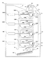
図1及び図2は、実施例1に係る不揮発性メモリの制御を行う画像形成装置の状態説明図であり、図1はカラー画像形成(多色画像形成)を行う画像形成装置の状態説明図であり、図2はモノクロ画像形成(単色画像形成)を行う画像形成装置の状態説明図である。 FIG. 1 and FIG. 2 are explanatory diagrams of the state of the image forming apparatus that controls the nonvolatile memory according to the first embodiment. FIG. 1 is an explanatory diagram of the state of the image forming apparatus that performs color image formation (multicolor image formation). FIG. 2 is an explanatory diagram of the state of the image forming apparatus that performs monochrome image formation (single color image formation).
(全体構成)
図1又は図2に示すカラー画像形成装置は、4個の感光ドラム101(101C,101Y,101M,101Bk)を備えており、4個の感光ドラム101は、図示しない駆動モータなどの駆動手段によって、図中反時計回りに回転駆動される。それぞれの感光ドラム101の周囲には、その回転方向に従って順に、次のようなものが構成される。まず、感光ドラム101表面を均一に帯電する帯電手段たる帯電ローラ104(104C,104Y,104M,104Bk)が配設される。また、画像情報に基づいてレーザビームを照射し感光ドラム101上の静電潜像を形成する露光手段たる露光装置108(108C,108Y,108M,108Bk)が配設される。また、静電潜像にトナーを付着させてトナー像として顕像化する現像手段たる現像器103(103C,103Y,103M,103Bk)が配設される。さらに、感光ドラム101上のトナー像を転写材に転写させる転写手段たる転写ローラ102(102C,102Y,102M,102Bk)が配設される。このようにして、画像形成手段たる画像形成部が構成されている。感光ドラム101と帯電ローラ104、現像器103は、一体的にカートリッジ化されカートリッジ106(106C,106Y,106M,106Bk)を形成している。これらのカートリッジは、画像形成装置本体に着脱可能である。
(overall structure)
The color image forming apparatus shown in FIG. 1 or 2 includes four photosensitive drums 101 (101C, 101Y, 101M, and 101Bk), and the four
給紙カセット150から給送された転写材は、搬送ベルト11aによって画像形成部へ搬送され、各色トナー像が順次転写されてカラー画像が記録された後、定着手段たる定着ユニット152で画像定着されて、排出ローラ対141によって排出部13へ排出される。
The transfer material fed from the
図3に画像形成装置100の構成を示すブロック図を示す。CPU200はROM201に格納されたプログラムを読み出し、後述する画像形成制御部210、搬送制御部211を制御して画像形成動作を行う。以下、各部の構成について順次説明する。
FIG. 3 is a block diagram illustrating the configuration of the
(画像形成部の構成)
像担持体としての各感光ドラム101は、直径30mmのアルミニウム製シリンダの外周面に有機光導伝体層(OPC)を塗布して構成したものである。感光ドラム101は、その両端部をフランジによって回転自在に支持されており、一方の端部に不図示の駆動モータから駆動力を伝達することにより、図の反時計回り方向に回転駆動される。
(Configuration of image forming unit)
Each
各帯電ローラ104は、ローラ状に形成された導電性ローラで、このローラを感光ドラム101表面に当接させるとともに、不図示の電源によって帯電バイアス電圧を印加することにより、感光ドラム101表面を一様に帯電させるものである。
Each charging roller 104 is a conductive roller formed in the shape of a roller. The roller is brought into contact with the surface of the
露光装置108は、不図示の駆動回路により、画像情報に基づいてレーザビームを照射し、感光ドラム101上に静電潜像を形成する。
The exposure device 108 irradiates a laser beam on the basis of image information with a drive circuit (not shown) to form an electrostatic latent image on the
現像器103は、それぞれブラック(Bk)、シアン(C)、マゼンタ(M)、イエロー(Y)の各色のトナーを収納したトナー収納部に位置し、感光ドラム101表面に隣接し、不図示の駆動部により回転駆動される。これとともに、図示しない現像バイアス電源により現像バイアス電圧を印加することにより現像を行う。トナー収納部には転写材の搬送方向上流側から順に、シアン、イエロー、マゼンタ、ブラックの各色トナーが収納されている。
The developing device 103 is positioned in a toner storage portion storing toner of each color of black (Bk), cyan (C), magenta (M), and yellow (Y), is adjacent to the surface of the
搬送ベルト11aの内側には、4個の感光ドラム101C、101Y、101M、101Bkに対応して、搬送ベルト11aに当接する転写ローラ102C、102Y、102M、102Bkがそれぞれ並設されている。これら転写ローラ102は、不図示の転写バイアス用電源で接続されており、転写ローラ102から正極性の電荷が搬送ベルト11aを介して転写材に印可される。そして、この電界により、感光ドラム101に接触中の転写材に、感光ドラム101上の負極性のトナー像が順次転写され、カラー画像が形成される。
Inside the
転写材に転写されたトナー画像は駆動回転する加熱ローラと従動回転する加圧ローラからなる定着ユニット152を通過する際に、熱及び圧力が印加されてトナー像が定着される。
When the toner image transferred to the transfer material passes through a fixing
(搬送部の構成)
転写材は給送部から給紙された後、搬送ベルト11aによって画像形成部へ搬送される。給紙部は、複数枚の転写材が給紙カセット150に収納されており、この給紙カセット150の近傍には、転写材を一枚ずつピックアップする半月状のピックアップローラ151が回転可能に設けられている。そしてピックアップローラ151の間欠回転によってピックアップされた転写材は、給送ローラ対140によって搬送ベルト11aへと給送される。
(Conveyor configuration)
The transfer material is fed from the feeding unit and then conveyed to the image forming unit by the
搬送手段を構成する転写材担持体としての搬送ベルト11aは、駆動ローラ11bと従動ローラ11c、11d、11eの4本のローラで張架支持され、全ての感光ドラム101C、101Y、101M、101Bkに対向して配設されている。この搬送ベルト11aは通常1010〜1014Ω・cmの体積固有抵抗を持たせた厚さ100〜150μmのエンドレスのフィルム状部材で構成される。そして、搬送ベルト11aは、感光ドラム101に対向する外周面に転写材を静電吸着して感光ドラム101に転写材を接触させるべく駆動ローラ11bによって循環移動する。これにより、転写材は搬送ベルト11aにより転写位置まで搬送され、感光ドラム101上のトナー像が転写される。
また、搬送ベルト11aの最上流位置には、搬送ベルト11aとともに転写材を挟持し、且つ転写材を搬送ベルト11aに吸着させる吸着ローラ153が配置されている。転写材の搬送に際しては、吸着ローラ153にバイアス電圧を印加することで、対向している接地された吸着ローラ153との間に電界を形成し、搬送ベルト11a及び転写材の間に誘電分極を発生させて両者に静電吸着力を生じさせるようになっている。
Further, an
(カラー画像形成時の構成とモノクロ画像形成時の構成)
カラー画像形成、及びモノクロ画像形成を行う場合の動作について説明する。
(Configuration for color image formation and monochrome image formation)
The operation when color image formation and monochrome image formation are performed will be described.
カラー画像形成を行う場合、現像離間板16により、4色全ての感光ドラム101と現像器103とを当接する位置に移動させ、4色全ての感光ドラム101にトナー像を形成する。
When color image formation is performed, the
一方、モノクロ画像形成を行う場合、画像形成には不必要なカートリッジ106C、106Y、106Mの性能劣化を低減するため、特定のカートリッジ106Bkのみを使用して画像形成を行う。従って、モノクロ画像形成時には、図2に示すように、現像離間板16によって、感光ドラム101Bkと現像器103Bkだけが当接するように移動することによって感光ドラム101Bk上にトナー像を形成する。その後、感光ドラム101上に形成された画像は、転写ローラ102により転写材上に転写され、定着ユニット152にてカラー画像及びモノクロ画像の定着が行われる。
On the other hand, when monochrome image formation is performed, image formation is performed using only a specific cartridge 106Bk in order to reduce performance deterioration of the
(カートリッジと不揮発性メモリの構成)
図4は、カートリッジ106が画像形成装置100に装着された状態を示す図である。カートリッジ106には不揮発性メモリ30(以下、単に「メモリ30」とする)(各色のカートリッジ106それぞれに、メモリ30Bk、メモリ30M、メモリ30Y、メモリ30Cを持つ)が搭載されている。カートリッジ106を画像形成装置100に装着すると、メモリ30と画像形成装置100の外部メモリ制御装置307(制御手段)が接続される構成となっている。メモリ30は、内部に不揮発性の記憶素子を内蔵しており、CPU200からの指示を受けて、外部メモリ制御装置307により、データの書込み、及びデータの読み出しを行う。
(Configuration of cartridge and non-volatile memory)
FIG. 4 is a diagram illustrating a state where the cartridge 106 is mounted on the
図5にメモリ30のデータ構造を示す。4色のカートリッジ106のメモリ30のメモリ格納領域には、アドレス00にモノクロ画像形成枚数(モノ画像形成枚数)、アドレス01にカラー画像形成枚数、アドレス02から08にその他のデータを記憶する。なお、モノクロ画像形成枚数とは、カートリッジ106Bkのみを使用して画像形成を行った際のカートリッジBkの使用状態を示す情報の一例である。また、カラー画像形成枚数とは、カートリッジ106M,Y,Cのいずれかを使用して画像形成を行った際のカートリッジM、Y、Cの使用状態を示す情報の一例である。使用状態に関する情報としては、画像形成枚数以外に、例えば、カートリッジを構成する部材の使用時間情報(駆動時間情報)であっても良い。
FIG. 5 shows the data structure of the memory 30. In the memory storage area of the memory 30 of the four-color cartridge 106, the number of monochrome images formed (number of mono images formed) at
また、アドレス09にはアドレス00から08までの値の誤り検知のためのチェックサム情報(チェックサムデータ)を記憶する。モノクロ画像形成枚数は、モノクロ画像形成を行った総数であり、モノクロ画像形成枚数を1枚単位で各色のメモリ30に記憶する。カラー画像形成枚数は、カラー画像形成を行った総数であり、カラー画像形成枚数を1枚単位で各色のメモリ30に記憶する。チェックサム情報はアドレス00から08までのデータの合計値を格納し、アドレス00から08までのデータの正当性のチェックに使用する。
Also, address 09 stores checksum information (checksum data) for error detection of
よって、アドレス00から08のいずれかを書換える場合には、アドレス09のチェックサム情報を書換える必要がある。つまり、アドレス00から08までのデータの書換え回数の総数が、アドレス09の書換え回数となり、アドレス09の書換え回数をメモリ30の書換え制限回数以下に制御する必要がある。本実施例では、メモリ30の書換え制限回数を1万回、カートリッジ106の印刷可能枚数を3千枚として説明する。
Therefore, when rewriting any of
カートリッジ106C、106M、106Yはカラー画像形成時に使用するカートリッジのため、カラー画像形成枚数が3千枚以上をカウントすると、寿命到達と判断して画像形成動作を停止し、ユーザにカートリッジ106の交換を要求する。カートリッジ106Bkは、カラー画像形成及びモノクロ画像形成に使用するため、カラー画像形成枚数とモノクロ画像形成枚数の合計が3千枚以上をカウントすると、寿命到達と判断して画像形成動作を停止し、ユーザにカートリッジの交換を要求する。モノクロ画像形成を行う場合には、カラー画像形成を行うカートリッジ106の印刷可能枚数は減少しないが、モノクロ画像形成枚数を書換える必要がある。よって、モノクロ画像形成の使用状況により、カラー画像形成を行うカートリッジ106(106C、106M、106Y)のメモリ30(30C、30M、30Y)の書換え回数は変化する。尚、本実施例ではメモリ30のアドレス02からアドレス08に対しては書換えを行わないものとして説明する。
Since the
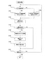
(不揮発性メモリ制御方法)
次に、本発明の特徴である不揮発性メモリの制御方法について図6、図7のフローチャートを用いて説明する。図6は画像形成装置の電源オン(ON)時の不揮発性メモリ制御に関わるフローチャートである。図7は画像形成動作時の不揮発性メモリ制御に関わるフローチャートである。なお、不揮発性メモリ制御とは、不揮発性メモリへのデータ書換え動作の制御を意味する。
(Nonvolatile memory control method)
Next, a non-volatile memory control method that is a feature of the present invention will be described with reference to the flowcharts of FIGS. FIG. 6 is a flowchart relating to nonvolatile memory control when the image forming apparatus is powered on. FIG. 7 is a flowchart relating to nonvolatile memory control during an image forming operation. Note that the nonvolatile memory control means control of data rewriting operation to the nonvolatile memory.
〜画像形成装置の電源オン時の不揮発性メモリの制御について〜
まず、図6を用いて画像形成装置100の電源オン時の不揮発性メモリ制御について説明する。
-Control of non-volatile memory at power-on of image forming device-
First, non-volatile memory control when the
CPU200は電源オン時に各メモリ30に記憶されたモノクロ画像形成枚数、カラー画像形成枚数を読み出し、読み出した結果をRAM202(図3参照)にそれぞれ記憶する(ステップ120、以下S120のように記す)。次に、各メモリ30を更新するタイミングを決定するためのカウンタ(以後、更新カウンタ、各カートリッジでカウント)の値をゼロに初期化する(S121)。次に、各メモリ30を更新するか否かを判断するために、前述した更新カウントと比較する更新しきい値C(各カートリッジで持つ)を図8のテーブルを用いて算出する(S121)。
The
図8のテーブルは、モノクロ画像形成枚数(書換え回数を類推できる情報)に応じて使用する更新しきい値Cを求めるテーブルである。モノクロ画像形成枚数が3000枚以下の場合は、カラー画像形成用カートリッジのメモリ30(30C、30M、30Y)は更新しきい値C=1、モノクロ画像形成用カートリッジのメモリ30(30Bk)は更新しきい値C=1となる。また、モノクロ画像形成枚数が3001枚以上6000枚以下の場合は、カラー画像形成用カートリッジのメモリ30は更新しきい値C=2、モノクロ画像形成用カートリッジのメモリ30は更新しきい値C=1となる。すなわち、モノクロ画像形成枚数が3001枚以上(所定回数以上)となったところで更新しきい値Cを変更する。以降の枚数の場合も同様にして求める。 The table of FIG. 8 is a table for obtaining an update threshold C to be used according to the number of monochrome image formations (information that can be used to infer the number of rewrites). When the number of monochrome image formations is 3000 or less, the memory 30 (30C, 30M, 30Y) of the color image formation cartridge is updated with the update threshold C = 1, and the memory 30 (30Bk) of the monochrome image formation cartridge is updated. The threshold value C = 1. When the number of monochrome image formation is 3001 or more and 6000 or less, the color image forming cartridge memory 30 has an update threshold value C = 2, and the monochrome image forming cartridge memory 30 has an update threshold value C = 1. It becomes. That is, the update threshold C is changed when the number of monochrome image formations reaches 3001 or more (a predetermined number of times or more). The same applies to the subsequent number of sheets.
〜画像形成動作時の不揮発性メモリの制御について〜
次に、図7を用いて画像形成時の不揮発性メモリ制御について説明する。
-Control of non-volatile memory during image forming operation-
Next, nonvolatile memory control during image formation will be described with reference to FIG.
まず、モノクロ画像形成を実施するか、カラー画像形成を実施するかを判断する(S130)。モノクロ画像形成を行う場合、RAM202上に記憶したそれぞれのカートリッジに対するモノクロ画像形成枚数を1カウントアップする(S131)。カラー画像形成を行う場合は、RAM202上に記憶したそれぞれのカートリッジに対するカラー画像形成枚数を1カウントアップする(S138)。次に、更新カウンタを1カウントアップする(S132)。
First, it is determined whether to perform monochrome image formation or color image formation (S130). When performing monochrome image formation, the number of monochrome image formations for each cartridge stored on the
次に、それぞれのカートリッジ106のメモリ30に対応する更新カウンタとそれぞれのカートリッジに対応する更新しきい値Cとを比較する(S133)。更新カウンタが更新しきい値C以上になったと判断した場合、RAM202に記憶したモノクロ画像形成枚数、カラー画像形成枚数の値をメモリ30に書き込んで書換え(S134)、更新カウンタをゼロに初期化する(S135)。そして、モノクロ画像形成枚数から図8のテーブルを用いて更新しきい値Cを再計算する(S136)。更新カウンタが更新しきい値C未満の場合は何も行わない。この動作を全ての画像形成が終了するまで繰り返す(S137)。
Next, the update counter corresponding to the memory 30 of each cartridge 106 is compared with the update threshold C corresponding to each cartridge (S133). When it is determined that the update counter is equal to or greater than the update threshold C, the values of the monochrome image formation number and the color image formation number stored in the
ここで、S133以降の処理を、モノクロ画像形成枚数が例えば4000枚程度となっている状態で説明する。この場合、図8に示すテーブルより、更新しきい値Cがカラー画像形成用カートリッジ106C、106M、106Yに対してはC=2、モノクロ画像形成用カートリッジ106Bkに対してはC=1となっている。S132で更新カウンタをカウントアップした結果、更新カウンタが1となったとすると、S133において、カラー画像形成用カートリッジ106C、106M、106Yに対しては更新カウンタが更新しきい値C未満となり、S137の処理に進む。
Here, the processing after S133 will be described in a state where the number of monochrome image formation is about 4000, for example. In this case, from the table shown in FIG. 8, the update threshold C is C = 2 for the color
一方、S133において、モノクロ画像形成用カートリッジ106Bkに対しては更新カウンタが更新しきい値C以上となり、S134以降の処理に進む。すなわち、S134でメモリ30Bkに対してのみ更新が行われる。また、モノクロ画像形成用カートリッジ106Bkに対する更新カウンタはS135で初期化される。尚、S136で算出されるモノクロ画像形成用カートリッジ106Bkに対する更新カウンタ値はC=1である。 On the other hand, in S133, for the monochrome image forming cartridge 106Bk, the update counter becomes equal to or greater than the update threshold C, and the process proceeds to S134 and subsequent steps. That is, only the memory 30Bk is updated in S134. The update counter for the monochrome image forming cartridge 106Bk is initialized in S135. Note that the update counter value for the monochrome image forming cartridge 106Bk calculated in S136 is C = 1.
画像形成が続行され、次にS133の処理を行う際には、S132で更新カウンタがカウントアップされた結果、カラー画像形成用カートリッジ106C、106M、106Yに対しては更新カウンタが2となる。
When image formation is continued and the next processing of S133 is performed, the update counter is incremented in S132, so that the update counter becomes 2 for the color
一方、モノクロ画像形成用カートリッジ106Bkに対しては、S135で初期化されたため更新カウンタは1となる。この場合、カラー画像形成用カートリッジ106C、106M、106Y、モノクロ画像形成用カートリッジ106Bkともに、S133でそれぞれの更新カウンタがそれぞれの更新しきい値C以上となる。このため、S134でメモリ30C、30M、30Y、30Bkの更新を行うことになる。
On the other hand, for the monochrome image forming cartridge 106Bk, the update counter becomes 1 because it was initialized in S135. In this case, in each of the color
このように、モノクロ画像形成枚数が4000枚程度の場合には、メモリ30C、30M、30Yの書換え頻度は2枚に1度となり、メモリ30Bkの書換え頻度(1枚毎)に比べて下がる。
As described above, when the number of monochrome images formed is about 4000, the rewriting frequency of the
以上の制御により、モノクロ画像形成枚数の増加に従い、更新しきい値Cの枚数を増やしていくことにより、カラー画像形成用カートリッジ106のメモリ30の更新頻度を下げている。 With the above control, the update frequency of the memory 30 of the color image forming cartridge 106 is lowered by increasing the number of update threshold values C as the number of monochrome image formation increases.
〜従来例との比較〜
図9に、本発明のモノクロ画像形成枚数によりメモリ30の更新頻度(図中、黒丸点で示す)を変更した場合のメモリ書換え回数(図中、実線で示す)と、他のメモリMの更新方法による書換え回数の比較結果を示す。比較する他のメモリMの更新方法として、最も書換え頻度の高い1枚毎の書換え(図中、破線で示す)と、3枚毎の書換え頻度による書換え回数(図中、一点鎖線で示す)を示す。
-Comparison with conventional examples-
FIG. 9 shows the number of times of memory rewriting (indicated by a solid line in the figure) when the update frequency of the memory 30 (indicated by a black dot in the figure) is changed according to the number of monochrome images formed according to the present invention, The comparison result of the number of rewrites by the method is shown. As another method of updating the memory M to be compared, the rewriting for each one with the highest rewriting frequency (indicated by a broken line in the figure) and the number of rewritings by the rewriting frequency for every three sheets (indicated by a one-dot chain line in the figure). Show.
図9で示す書換え回数は、カラー画像形成用カートリッジ106に対する書換え回数の見積もり数であり、カラー画像形成可能枚数3000枚を行うためのメモリ30の書換え回数最大値3000回を含んだ値となっている。最も書換え頻度の高い、1枚毎に書換える方法は、RAM202上のデータが不揮発性メモリに書き込まれる前に、カートリッジの着脱や画像形成装置本体の電源オフ等が発生した場合のデータ損失に対しては有効な制御である。
The number of rewrites shown in FIG. 9 is an estimated number of rewrites for the color image forming cartridge 106, and includes a maximum value of 3000 rewrites in the memory 30 for performing 3000 color image formable sheets. Yes. The most frequently rewritten method of rewriting for each sheet is for data loss when the cartridge is attached / detached or the image forming apparatus main unit is turned off before the data on the
しかしながら、モノクロ画像形成を7000枚実施した時点で、メモリMの書換え制限回数に到達してしまう。3枚毎に書換える方法では、1枚毎に書換える方法と比較して、約3倍のモノクロ画像形成によるメモリ30の書換えを可能にするものの、前述した例におけるデータ損失に対しては不利になる。本発明による方法では、モノクロ画像形成枚数が所定数に到達するまでは1枚毎にメモリ30の書換えを行い、モノクロ画像形成枚数の増加に従い、メモリ30の書換え頻度を下げている。この方法により、一般的な使用状況と推測されるモノクロ画像形成実施時には、データ損失をなるべく防止し、モノクロ画像形成を多用するユーザに対しても、カラー画像形成用カートリッジ106のメモリ30の書換え回数を抑えることが可能となる。 However, when 7000 monochrome images are formed, the memory M reaches the rewrite limit number. The method of rewriting every three sheets enables rewriting of the memory 30 by forming a monochrome image about three times as much as the method of rewriting every one sheet, but is disadvantageous for data loss in the above-described example. become. In the method according to the present invention, the memory 30 is rewritten one by one until the number of monochrome image formation reaches a predetermined number, and the frequency of rewriting of the memory 30 is reduced as the number of monochrome image formation increases. This method prevents data loss as much as possible during monochrome image formation, which is assumed to be a general usage situation, and allows the user who frequently uses monochrome image formation to rewrite the memory 30 of the color image forming cartridge 106. Can be suppressed.
尚、モノクロ画像形成を行うカートリッジ106Bkのメモリ30Bkは、カラー画像形成、モノクロ画像形成のどちらの使用においても、1枚画像形成を行う度にメモリ30Bkを更新しても書換え制限回数を超えることはない。これは、カートリッジの印刷可能枚数に対してメモリ30Bkの書換え制限回数の方か大きいためである。よって図8のテーブルのモノクロ画像形成用カートリッジに対する更新しきい値Cは、全て1として、データ損失の少ない値を使用している。 Note that the memory 30Bk of the cartridge 106Bk that performs monochrome image formation does not exceed the rewrite limit number even if the memory 30Bk is updated each time one image is formed, regardless of whether color image formation or monochrome image formation is used. Absent. This is because the rewrite limit number of the memory 30Bk is larger than the printable number of cartridges. Therefore, the update threshold values C for the monochrome image forming cartridges in the table of FIG. 8 are all set to 1, and values with less data loss are used.
上記説明した不揮発性メモリの制御方法により、モノクロ画像形成枚数より不揮発性メモリの書換え回数を判断し、書換え回数の増加に伴って書換え頻度を変更することにより、ユーザの使用状況に応じた不揮発性メモリの書換え頻度を使用することが可能となる。そして、データの信頼性の低下を軽減または抑えた不揮発性メモリ制御を実現することが可能となる。 The nonvolatile memory control method described above determines the number of times the nonvolatile memory is rewritten from the number of monochrome images formed, and changes the frequency of rewriting as the number of times of rewriting increases. It is possible to use the memory rewrite frequency. Then, it is possible to realize nonvolatile memory control that reduces or suppresses a decrease in data reliability.
実施例2においても、実施例1で、図1〜図5を参照して説明した画像形成装置のシステム構成が使用される。従って、画像形成装置及び画像形成装置の画像形成動作の説明は実施例1を援用し、ここでは再度の説明を省略する。また、不揮発性メモリの制御フローについても図6及び図7を援用するため説明を省略する。 Also in the second embodiment, the system configuration of the image forming apparatus described in the first embodiment with reference to FIGS. 1 to 5 is used. Accordingly, the description of the image forming apparatus and the image forming operation of the image forming apparatus uses the first embodiment, and the description thereof is omitted here. Also, the control flow of the nonvolatile memory will be omitted because it uses FIGS. 6 and 7.
実施例1では、図8のテーブルにより、モノクロ画像形成枚数に応じて更新しきい値Cを求め、不揮発性メモリの更新頻度を変更する方法について説明した。本実施例では、図8のかわりに、図10に示すテーブルにより更新しきい値Cを求めた場合の不揮発性メモリ制御方法について説明する。 In the first embodiment, the method of obtaining the update threshold C according to the number of monochrome images formed using the table of FIG. 8 and changing the update frequency of the nonvolatile memory has been described. In this embodiment, a nonvolatile memory control method when the update threshold value C is obtained using the table shown in FIG. 10 instead of FIG. 8 will be described.
(不揮発性メモリの制御方法)
〜本実施例における更新しきい値Cを求めるためのテーブル〜
実施例1で説明した通り、電源オン時の更新しきい値Cの算出(S121)(図6のフローチャート)、及び、画像形成時の更新しきい値Cの算出時(S136)(図7のフローチャート)において図10に示すテーブルにより更新しきい値Cを求める。図10は、モノクロ画像形成を行う際(第一の画像形成モード)のモノクロ画像形成枚数と、カラー画像形成を行う際(第二の画像形成モード)のカラー画像形成枚数の比に応じて更新しきい値Cを選択するテーブルである。モノクロ画像形成枚数がカラー画像形成枚数に対して、0倍から2倍以下の場合には、カラー画像形成用カートリッジのメモリ30は更新しきい値C=1を選択する。2倍より大きく5倍以下の場合には、カラー画像形成用カートリッジのメモリ30は更新しきい値C=2を選択する。
(Nonvolatile memory control method)
~ Table for obtaining the update threshold C in this embodiment ~
As described in the first embodiment, calculation of the update threshold value C when the power is turned on (S121) (flow chart of FIG. 6), and calculation of the update threshold value C during image formation (S136) (FIG. 7). In the flowchart, the update threshold value C is obtained from the table shown in FIG. FIG. 10 is updated according to the ratio of the number of monochrome images formed when forming a monochrome image (first image forming mode) and the number of color images formed when forming a color image (second image forming mode). It is a table for selecting a threshold value C. When the number of monochrome images formed is 0 to 2 times the number of color images formed, the memory 30 of the color image forming cartridge selects the update threshold C = 1. If it is greater than 2 times and less than 5 times, the memory 30 of the color image forming cartridge selects the update threshold C = 2.
すなわち、モノクロ画像形成枚数がカラー画像形成枚数に対して、2倍以上(所定値以上)となったところで、更新しきい値Cを変更する。以降の倍率の場合も同様にして更新しきい値Cを求める。一方、モノクロ画像形成用カートリッジのメモリ30は、いずれの比に対しても更新しきい値C=1となる。 That is, the update threshold value C is changed when the number of monochrome image formations becomes twice or more (predetermined value or more) with respect to the number of color image formations. The update threshold value C is obtained in the same manner for the subsequent magnifications. On the other hand, the memory 30 of the monochrome image forming cartridge has the update threshold C = 1 for any ratio.
以上の制御により、モノクロ画像形成枚数のカラー画像形成枚数に対する倍率の増加に従い、更新しきい値Cの枚数を増やしていくことにより、カラー画像形成用カートリッジ106のメモリ30の更新頻度を下げている。 With the above control, the update frequency of the memory 30 of the color image forming cartridge 106 is lowered by increasing the number of update threshold values C as the magnification of the monochrome image formation number increases with respect to the color image formation number. .
〜従来例との比較〜
図11に、本発明のモノクロ画像形成枚数とカラー画像形成枚数の比率により、メモリ30の更新頻度(図中、点線で示す)を変更した場合のメモリ書換え回数(図中、実線で示す)と、他のメモリMの更新方法による書換え回数の比較結果を示す。比較する他のメモリMの更新方法として、最も書換え頻度の高い1枚毎の書換え(図中、一点鎖線で示す)と、3枚毎の書換え頻度による書換え回数(図中、二点鎖線で示す)を示す。また、モノクロ画像形成枚数の最大値を破線で示す。
-Comparison with conventional examples-
FIG. 11 shows the number of times of memory rewriting (indicated by a solid line in the figure) when the update frequency of the memory 30 (indicated by a dotted line in the figure) is changed according to the ratio of the number of monochrome images to the number of color images formed in the present invention. The comparison result of the number of rewrites by another memory M update method is shown. As another method of updating the memory M to be compared, rewriting for each one with the highest rewriting frequency (indicated by a one-dot chain line in the figure) and the number of rewritings by the rewriting frequency for every three sheets (indicated by a two-dot chain line in the figure) ). Further, the maximum value of the number of monochrome images formed is indicated by a broken line.
図11で示す書換え回数は、カラー画像形成用カートリッジ106に対する書換え回数の見積もり数であり、カラー画像形成可能枚数3000枚を行うためのメモリ30の書換え回数最大値3000回を含んだ値となっている。最も書換え頻度の高い、1枚毎に書換える方法では、RAM202上のデータが不揮発性メモリに書き込まれる前に、カートリッジの着脱や画像形成装置本体の電源オフ等が発生した場合のデータ損失に対しては有効な制御である。しかしながら、モノクロ画像形成を7000枚実施した時点で、メモリMの書換え制限回数に到達してしまう。3枚毎に書換える方法では、1枚毎に書換える方法と比較して、約3倍のモノクロ画像形成によるメモリ30の書換えを可能にするものの、前述した例におけるデータ損失に対しては不利になる。本発明による方法では、モノクロ画像形成枚数のカラー画像形成枚数に対する比率が所定値に到達するまでは1枚毎にメモリ30の書換えを行い、比率の増加に従い、メモリ30の書換え頻度を下げている。この方法により、一般的な使用状況と推測されるモノクロ画像形成実施時には、データ損失をなるべく防止し、モノクロ画像形成を多用するユーザに対しても、カラー画像形成用カートリッジ106のメモリ30の書換え回数を抑えることが可能となる。
The number of rewrites shown in FIG. 11 is an estimated number of rewrites for the color image forming cartridge 106, and includes a maximum value of 3000 rewrites in the memory 30 for performing 3000 color image formable sheets. Yes. In the method of rewriting one by one, which is the most frequently rewritten, the data loss caused when the cartridge is attached or detached or the image forming apparatus main unit is turned off before the data on the
尚、モノクロ画像形成を行うカートリッジ106Bkのメモリ30Bkは、カラー画像形成、モノクロ画像形成のどちらの使用においても、1枚画像形成を行う度にメモリ30Bkを更新しても書換え制限回数を超えることはない。これは、カートリッジの印刷可能枚数に対してメモリ30Bkの書換え制限回数の方か大きいためである。よって図11のテーブルは全て1として、データ損失の少ない値を使用している。 Note that the memory 30Bk of the cartridge 106Bk that performs monochrome image formation does not exceed the rewrite limit number even if the memory 30Bk is updated each time one image is formed, regardless of whether color image formation or monochrome image formation is used. Absent. This is because the rewrite limit number of the memory 30Bk is larger than the printable number of cartridges. Therefore, all the tables in FIG. 11 are set to 1, and values with less data loss are used.
上記説明した不揮発性メモリの制御方法により、モノクロ画像形成枚数とカラー画像形成枚数から不揮発性メモリの書換え回数を判断し、モノクロ画像形成枚数のカラー画像形成枚数に対する比率より不揮発性メモリの書換え頻度を変更する。これにより、ユーザの使用状況に応じた不揮発性メモリの書換え頻度を使用することが可能となり、データの信頼性の低下を軽減、または、抑えた不揮発性メモリの制御を実現することが可能となる。 The nonvolatile memory control method described above determines the number of times the nonvolatile memory is rewritten from the number of monochrome images formed and the number of color images formed, and determines the rewrite frequency of the nonvolatile memory from the ratio of the number of monochrome images formed to the number of color images formed. change. As a result, it becomes possible to use the non-volatile memory rewriting frequency according to the usage status of the user, and it is possible to realize a control of the non-volatile memory that reduces or suppresses a decrease in data reliability. .
実施例3においても、実施例1で、図1〜図5を参照して説明した画像形成装置のシステム構成が使用される。従って、画像形成装置及び画像形成装置の画像形成動作の説明は実施例1を援用し、ここでは再度の説明は省略する。 Also in the third embodiment, the system configuration of the image forming apparatus described in the first embodiment with reference to FIGS. 1 to 5 is used. Accordingly, the description of the image forming apparatus and the image forming operation of the image forming apparatus uses the first embodiment, and the description thereof is omitted here.
次に、本発明の特徴である不揮発性メモリの制御方法について図12、図13のフローチャートを用いて説明する。図12は画像形成装置の電源オン(ON)時の不揮発性メモリ制御に関わるフローチャートである。図13は画像形成動作時の不揮発性メモリの制御に関わるフローチャートである。 Next, a non-volatile memory control method that is a feature of the present invention will be described with reference to the flowcharts of FIGS. FIG. 12 is a flowchart relating to nonvolatile memory control when the image forming apparatus is powered on. FIG. 13 is a flowchart relating to the control of the nonvolatile memory during the image forming operation.
(不揮発性メモリの制御方法)
〜画像形成装置の電源オン時の不揮発性メモリの制御について〜
まず、図12を用いて画像形成装置の電源オン時の不揮発性メモリ制御について説明する。
(Nonvolatile memory control method)
-Control of non-volatile memory at power-on of image forming device-
First, non-volatile memory control when the image forming apparatus is turned on will be described with reference to FIG.
CPU200は電源オン時に各メモリ30に記憶されたモノクロ画像形成枚数、カラー画像形成枚数を読み出し、読み出した結果をRAM202にそれぞれ記憶する(S100)。次に、メモリ30を更新するタイミングを決定するためのカウンタ(以後、更新カウンタ、各カートリッジでカウント)の値をゼロに初期化する(S101)。
The
〜画像形成動作時の不揮発性メモリの制御について〜
次に、図13を用いて画像形成時の不揮発性メモリ制御について説明する。
-Control of non-volatile memory during image forming operation-
Next, nonvolatile memory control during image formation will be described with reference to FIG.
まず、モノクロ画像形成を実施するか、カラー画像形成を実施するかを判断する(S110)。モノクロ画像形成を行う場合(単色画像形成モード)、RAM202上に記憶したそれぞれのカートリッジに対するモノクロ画像形成枚数を1カウントアップする(S111)。次に、前述した、更新カウンタをA値カウントアップする(S112)。カラー画像形成を行う場合(多色画像形成モード)は、RAM202上に記憶したカラー画像形成枚数を1カウントアップする(S117)。次に、更新カウンタをB値カウントアップする(S118)。
First, it is determined whether to perform monochrome image formation or color image formation (S110). When performing monochrome image formation (single color image formation mode), the number of monochrome image formations for each cartridge stored in the
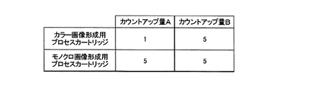
本実施例ではA値及びB値は、図14に示すテーブルの値を用いる。モノクロ画像形成を行うカートリッジ106Bkのメモリ30Bkに対しては、カウントアップ量A値、B値はともに5を用いる。カラー画像形成を行うカートリッジ106C、106Y、106Mのメモリ30C、メモリ30Y、メモリ30Mは、カウントアップ量A値=1、B値=5を用いる。次に、各メモリ30を更新するか否かを判断する更新しきい値Cと更新カウンタを比較する(S113)。本実施例ではC=5とする。更新カウンタが更新しきい値C以上になったと判断した場合、RAM202に記憶した値(所定の情報)でメモリ30を書換え(S114)、更新カウンタをゼロに初期化する(S115)。更新カウンタが更新しきい値C未満の場合は何も行わない。この動作を全ての画像形成が終了するまで繰り返す(S116)。
In this embodiment, the values in the table shown in FIG. 14 are used as the A value and the B value. For the memory 30Bk of the cartridge 106Bk that performs monochrome image formation, 5 is used as both the count-up amount A value and B value. The
ここで、具体的な値を用いて説明する。全ての更新カウンタが初期化された状態で画像形成動作が開始されたとする。S110でモノクロ画像形成を行う場合、図14により、モノクロ画像形成用カートリッジ106Bkに対してはA=5、カラー画像形成用カートリッジ106C、106M、106Yに対してはA=1が選択される。このため、S112では、モノクロ画像形成用カートリッジ106Bkに対する更新カウンタは5、カラー画像形成用カートリッジ106C、106M、106Yに対する更新カウンタは1となる。次に、S113の判断においては、モノクロ画像形成用カートリッジ106Bkでは、更新カウンタの値が更新しきい値C(=5)以上となり、S114でメモリ30Bkの書換え、更新を行いS115で更新カウンタを初期化する。
Here, description will be made using specific values. Assume that the image forming operation is started with all the update counters initialized. When monochrome image formation is performed in S110, A = 5 is selected for the monochrome image forming cartridge 106Bk and A = 1 is selected for the color
一方、カラー画像形成用カートリッジ106C、106M、106Yでは、更新カウンタの値が更新しきい値C未満となるので、メモリ30C、30Y、30Mの書換え、更新は行わず、S116の処理に進む。その後、モノクロ画像形成が引き続き行われるとする。そうすると、カラー画像形成用カートリッジ106C、106M、106Yの更新カウンタが1(=A)ずつカウントアップされ、5になったときにメモリ30C、30M、30Yに対して書換え、更新が行われることになる。
On the other hand, in the color
このように、モノクロ画像形成を行う場合には、メモリ30C、30M、30Yの書換え頻度は5枚に1度となり、メモリ30Bkの書換え頻度(1枚毎)に比べて下がる。
As described above, when monochrome image formation is performed, the rewrite frequency of the
一方、S110でカラー画像形成を行う場合は、図14よりカウントアップ量は、モノクロ画像形成用カートリッジ106Bk、カラー画像形成用カートリッジ106C、106M、106YともにB=5である。従って、S113で、ともに更新カウンタの値が更新しきい値C(=5)以上となるため、全てのメモリ30C、30Y、30M、30Bkに対して、書換え、更新が行われる。
On the other hand, when color image formation is performed in S110, the count-up amount is B = 5 for the monochrome image forming cartridge 106Bk and the color
以上の制御により、本実施例において用いたカウントアップ量A、B及び更新しきい値Cを用いると、カラー画像形成を行うカートリッジに対しては、カラー画像形成を行う場合には1枚画像形成を行う度にメモリ30の値を更新することになる。一方、モノクロ画像形成を行う場合には5枚画像形成を行う度にメモリ30の値を更新することになる。モノクロ画像形成を行うカートリッジに対しては、カラー画像形成、モノクロ画像形成どちらにおいても1枚画像形成を行う度にメモリ30の値を更新することになる。 With the above control, when the count-up amounts A and B and the update threshold value C used in the present embodiment are used, a single image is formed when a color image is formed for a cartridge that forms a color image. The value of the memory 30 is updated every time the operation is performed. On the other hand, when a monochrome image is formed, the value in the memory 30 is updated every time five images are formed. For a cartridge that performs monochrome image formation, the value of the memory 30 is updated each time one image is formed in both color image formation and monochrome image formation.
すると、カラー画像形成を行うカートリッジのメモリ30は、書込み制限回数1万回からカラー画像形成による印字可能枚数の書換えに必要な3千回を差し引いた7千回に対して、5枚に1回の割合でモノクロ画像形成による枚数を書換える。このため、約3万5千枚のモノクロ画像形成を行うまでデータの信頼性を保つことが可能となる。また、カラー画像形成を行う場合は、カートリッジの印刷可能枚数よりもメモリ30の書込み制限回数の方が大きいため、書換え制限回数を超えることはない。モノクロ画像形成を行うカートリッジのメモリ30Bkは、カートリッジの印刷可能枚数よりもメモリの書込み制限回数の方か大きい。このため、カラー画像形成、モノクロ画像形成どちらにおいても、1枚画像形成を行う度にメモリ30Bkを更新しても書換え制限回数を超えることはない。 Then, the memory 30 of the cartridge that performs the color image formation is once every five sheets, instead of 7,000 times obtained by subtracting 3,000 times necessary for rewriting the number of printable sheets by color image formation from the write limit number of 10,000 times. The number of sheets formed by monochrome image formation is rewritten at the rate of. Therefore, it is possible to maintain data reliability until approximately 35,000 monochrome images are formed. Further, when color image formation is performed, the number of times of writing in the memory 30 is larger than the number of printable sheets of the cartridge, so that the number of times of rewriting is not exceeded. The memory 30Bk of the cartridge that performs monochrome image formation has a larger number of memory write limits than the printable number of cartridges. Therefore, in both color image formation and monochrome image formation, even if the memory 30Bk is updated every time one image is formed, the rewrite limit number is not exceeded.
本制御により、モノクロ画像形成時とカラー画像形成時とで不揮発性メモリの書換え頻度を変化させる。これにより、一般的な使用状況と推測されるモノクロ画像形成枚数から、カラー画像形成を行うメモリ30の書換え頻度を一律下げた場合に比較して(例えば全て5枚に1回の割合で不揮発性メモリを更新する等の制御)、次のようなことが可能となる。 By this control, the rewrite frequency of the nonvolatile memory is changed between the monochrome image formation and the color image formation. As a result, compared to the case where the rewrite frequency of the memory 30 that performs color image formation is uniformly reduced from the number of monochrome images formed that is assumed to be a general use situation (for example, non-volatile at a rate of once every 5 sheets). Control such as updating the memory) makes it possible to:
すなわち、RAM202上のデータが不揮発性メモリに書き込まれる前に、カートリッジの着脱や画像形成装置本体の電源オフ等によってデータが損失してしまうことを削減させることが可能となる。また、モノクロ画像形成を多用するユーザに対しても、カラー画像形成用カートリッジの不揮発性メモリの信頼性を維持することが可能となる。本実施例で用いたカウントアップ量A,B及び更新しきい値Cは一例であり、この限りではない。
That is, it is possible to reduce the loss of data due to the attachment / detachment of the cartridge or the power-off of the image forming apparatus main body before the data on the
実施例1〜3において、不揮発性メモリに画像形成枚数を記憶し、画像形成枚数に応じた不揮発性メモリの制御方法を示した。もちろん、画像形成枚数に限定される訳ではない。例えば、装置の駆動時間やクラッチ等のオン/オフ回数等を記憶する構成においても、同様の効果を得ることが可能である。また、例えば、駆動時間や駆動回数等により、不揮発性メモリの書換え回数を判断して不揮発性メモリの更新処理の頻度を変化させる構成を用いても、同様の効果を得ることが可能である。 In the first to third embodiments, a method for storing the number of image formations in the nonvolatile memory and controlling the nonvolatile memory according to the number of image formations is shown. Of course, the number of images formed is not limited. For example, the same effect can be obtained even in a configuration that stores the drive time of the device, the number of times of ON / OFF of the clutch, and the like. Further, for example, the same effect can be obtained by using a configuration in which the frequency of renewal processing of the nonvolatile memory is changed by determining the number of times the nonvolatile memory is rewritten based on the driving time or the number of times of driving.
尚、本発明では、実施形態の機能を実現するソフトウェアのプログラムコードを記録した記憶媒体をシステム或は装置に提供する。そして、そのシステム或は装置のコンピュータ(又はCPUやMPU)が記憶媒体に格納されたプログラムコードを読み出し実行することによっても達成される。この場合、記憶媒体から読み出されたプログラムコード自体が前述した実施例の機能を実現することになり、そのプログラムコードを記憶した記憶媒体は本発明を構成することになる。このようなプログラムコードを供給するための記憶媒体としては、例えば、フロッピィ(登録商標)ディスク、ハードディスク、光ディスク、光磁気ディスク、CD−ROM、CD−R、磁気テープ、不揮発性のメモリカード、ROMなどを用いることができる。 In the present invention, a storage medium in which a program code of software that implements the functions of the embodiments is recorded is provided to the system or apparatus. This can also be achieved by the computer (or CPU or MPU) of the system or apparatus reading and executing the program code stored in the storage medium. In this case, the program code itself read from the storage medium realizes the functions of the above-described embodiments, and the storage medium storing the program code constitutes the present invention. As a storage medium for supplying such a program code, for example, a floppy (registered trademark) disk, hard disk, optical disk, magneto-optical disk, CD-ROM, CD-R, magnetic tape, nonvolatile memory card, ROM Etc. can be used.
また、コンピュータが読み出したプログラムコードを実行することにより、前述した実施例の機能が実現されるだけでなく、次のような場合も含まれる。すなわち、そのプログラムコードの指示に基づき、コンピュータ上で稼動しているOS(オペレーティングシステム)などが実際の処理の一部又は全部を行い、その処理によって前述した実施の形態の機能が実現される場合も含まれている。 Further, by executing the program code read by the computer, not only the functions of the above-described embodiments are realized, but also the following cases are included. That is, when the OS (operating system) running on the computer performs part or all of the actual processing based on the instruction of the program code, and the functions of the above-described embodiments are realized by the processing. Is also included.
さらに、記憶媒体から読み出されたプログラムコードが、コンピュータに挿入された機能拡張ボードやコンピュータに接続された機能拡張ユニットに備わるメモリに書きこまれた後、そのプログラムコードの指示に基づき、次のように実現される場合も含む。すなわち、その機能拡張ボードや機能拡張ユニットに備わるCPUなどが実際の処理の一部又は全部を行い、その処理によって前述した実施の形態の機能が実現される場合も含む。 Furthermore, after the program code read from the storage medium is written to the memory provided in the function expansion board inserted into the computer or the function expansion unit connected to the computer, the following is executed based on the instruction of the program code. It includes the case where it is realized. That is, the case where the CPU of the function expansion board or function expansion unit performs part or all of the actual processing and the functions of the above-described embodiments are realized by the processing.
また、上記実施例の機能を実現するソフトウェアのプログラムコードがネットワークを介して配信されることにより、次のように達成される。すなわち、システム又は装置のハードディスクやメモリ等の記憶手段又はCD−RW、CD−R等の記憶媒体に格納される。そして、そのシステム又は装置のコンピュータ(又はCPUやMPU)が当該記憶手段や当該記憶媒体に格納されたプログラムコードを読み出して実行することによっても、達成される。 Further, the program code of the software that realizes the functions of the above-described embodiments is distributed through the network, thereby achieving the following. That is, it is stored in a storage means such as a hard disk or a memory of a system or apparatus, or a storage medium such as a CD-RW or CD-R. This can also be achieved by the computer (or CPU or MPU) of the system or apparatus reading and executing the program code stored in the storage means or the storage medium.
11a 搬送ベルト
13 排出部
16 現像離間板
30 メモリ(不揮発性メモリ)
100 画像形成装置
101 感光ドラム
102 転写ローラ
103 現像器
104 帯電ローラ
106 カートリッジ
108 露光装置
141 排出ローラ対
150 給紙カセット
151 ピックアップローラ
152 定着ユニット
200 CPU
201 ROM
202 RAM
210 画像形成制御部
211 搬送制御部
307 外部メモリ制御装置(制御手段)
DESCRIPTION OF
201 ROM
202 RAM
210 Image
Claims (8)
前記不揮発性メモリの書き込み動作を制御する制御手段と、を備え、
前記制御手段は、前記複数の画像形成手段のうち、特定の画像形成手段を用いて画像形成を行う際に、前記画像形成に用いない他の画像形成手段の不揮発性メモリに、前記特定の画像形成手段の使用量に関する情報を記憶し、
前記制御手段は、前記使用量に関する情報に従って、前記他の画像形成手段の不揮発性メモリの書き込み頻度を低下させることを特徴とする画像形成装置。 A plurality of image forming means having a nonvolatile memory;
Control means for controlling a write operation of the nonvolatile memory,
When the control unit performs image formation using a specific image forming unit among the plurality of image forming units, the control unit stores the specific image in a non-volatile memory of another image forming unit not used for the image formation. Storing information about the amount of use of the forming means,
The image forming apparatus according to claim 1, wherein the control unit reduces the writing frequency of the non-volatile memory of the other image forming unit in accordance with the information on the usage amount.
前記複数のカートリッジのうち特定のカートリッジを用いて画像形成を行う第一の画像形成モードと、前記第一の画像形成モードで用いるカートリッジとは異なる他のカートリッジを用いて画像形成を行う第二の画像形成モードとを切り換え可能であり、
前記制御手段は、前記複数のカートリッジの夫々の不揮発性メモリへのデータ書き込み動作を制御し、
前記第一の画像形成モードで画像形成を行う際に、前記制御手段は、前記他のカートリッジの前記不揮発性メモリに前記特定のカートリッジの使用量に関する情報を記憶し、前記第二の画像形成モードで画像形成を行う際に、前記制御手段は、前記他のカートリッジの前記不揮発性メモリに前記他のカートリッジの使用量に関する情報を記憶し、前記不揮発性メモリに記憶された、前記特定のカートリッジの使用量に関する情報に応じて前記他のカートリッジの不揮発性メモリへの書き込み頻度を低下させることを特徴とする画像形成装置。 A plurality of cartridges having a nonvolatile memory are detachable, and an image forming apparatus comprising a control means for controlling a writing operation of the nonvolatile memory,
A first image forming mode in which image formation is performed using a specific cartridge among the plurality of cartridges, and a second image in which image formation is performed using a cartridge different from the cartridge used in the first image forming mode. The image formation mode can be switched,
Wherein the control means controls the data write operation to the plurality of cartridges each of the non-volatile memory,
When performing image formation in the first image forming mode, the control unit stores information on the usage amount of the specific cartridge in the nonvolatile memory of the other cartridge, and the second image forming mode When the image formation is performed, the control unit stores information on the usage amount of the other cartridge in the nonvolatile memory of the other cartridge, and stores the information on the specific cartridge stored in the nonvolatile memory. An image forming apparatus, wherein the frequency of writing to the nonvolatile memory of the other cartridge is reduced in accordance with information on the usage amount.
前記制御手段は、前記比較手段による比較結果により前記他のカートリッジの前記不揮発性メモリの書き込み頻度を低下させることを特徴とする請求項4に記載の画像形成装置。 Comparing means for comparing information on the usage amount of the specific cartridge and information on the usage amount of the other cartridge,
The image forming apparatus according to claim 4 , wherein the control unit reduces the writing frequency of the nonvolatile memory of the other cartridge based on a comparison result by the comparison unit.
前記複数の画像形成手段の夫々は、色の異なる現像剤を収容しており、前記特定の画像形成手段は、ブラックの現像剤を収容しており、前記使用量に関する情報は、現像剤を用いて画像を形成したシートの枚数を含むことを特徴とする請求項4乃至7のいずれか1項に記載の画像形成装置。 The image forming apparatus is a color image forming apparatus,
Each of the plurality of image forming units stores developers of different colors, the specific image forming unit stores a black developer, and information on the usage amount uses a developer. the image forming apparatus according to any one of claims 4 to 7, characterized in that it comprises a number of sheets having an image formed Te.
Priority Applications (3)
| Application Number | Priority Date | Filing Date | Title |
|---|---|---|---|
| JP2009094864A JP5383294B2 (en) | 2008-04-25 | 2009-04-09 | Image forming apparatus |
| US12/427,358 US8493607B2 (en) | 2008-04-25 | 2009-04-21 | Control apparatus of non-volatile memory and image forming apparatus |
| US13/926,907 US8995004B2 (en) | 2008-04-25 | 2013-06-25 | Control apparatus of non-volatile memory and image forming apparatus |
Applications Claiming Priority (3)
| Application Number | Priority Date | Filing Date | Title |
|---|---|---|---|
| JP2008115576 | 2008-04-25 | ||
| JP2008115576 | 2008-04-25 | ||
| JP2009094864A JP5383294B2 (en) | 2008-04-25 | 2009-04-09 | Image forming apparatus |
Publications (3)
| Publication Number | Publication Date |
|---|---|
| JP2009282505A JP2009282505A (en) | 2009-12-03 |
| JP2009282505A5 JP2009282505A5 (en) | 2012-05-31 |
| JP5383294B2 true JP5383294B2 (en) | 2014-01-08 |
Family
ID=41214701
Family Applications (1)
| Application Number | Title | Priority Date | Filing Date |
|---|---|---|---|
| JP2009094864A Expired - Fee Related JP5383294B2 (en) | 2008-04-25 | 2009-04-09 | Image forming apparatus |
Country Status (2)
| Country | Link |
|---|---|
| US (2) | US8493607B2 (en) |
| JP (1) | JP5383294B2 (en) |
Families Citing this family (6)
| Publication number | Priority date | Publication date | Assignee | Title |
|---|---|---|---|---|
| JP5171448B2 (en) * | 2007-07-31 | 2013-03-27 | キヤノン株式会社 | Image forming apparatus and control method thereof |
| JP2012226575A (en) * | 2011-04-20 | 2012-11-15 | Mitsubishi Electric Corp | Method for storing data in non-volatile memory and control device |
| US20120327451A1 (en) * | 2011-06-23 | 2012-12-27 | Steven Miller | Method of Transforming an Imaging Machine |
| JP5948976B2 (en) * | 2012-03-06 | 2016-07-06 | 富士ゼロックス株式会社 | Image forming apparatus and information processing apparatus |
| JP6141116B2 (en) * | 2013-06-20 | 2017-06-07 | キヤノン株式会社 | Image forming apparatus |
| JP7457212B2 (en) | 2022-02-24 | 2024-03-27 | 株式会社デンソートリム | engine control device |
Family Cites Families (15)
| Publication number | Priority date | Publication date | Assignee | Title |
|---|---|---|---|---|
| DE69034227T2 (en) * | 1989-04-13 | 2007-05-03 | Sandisk Corp., Sunnyvale | EEprom system with block deletion |
| JPH0573433A (en) * | 1991-09-12 | 1993-03-26 | Hitachi Ltd | Storage device |
| JP3251968B2 (en) * | 1992-01-20 | 2002-01-28 | 富士通株式会社 | Semiconductor storage device |
| JPH05216774A (en) * | 1992-02-04 | 1993-08-27 | Nec Eng Ltd | Memory protecting system |
| JP2866521B2 (en) | 1992-03-06 | 1999-03-08 | シャープ株式会社 | Copier memory system |
| JPH06138730A (en) | 1992-10-23 | 1994-05-20 | Murata Mach Ltd | Image forming device |
| JPH07271699A (en) | 1994-03-31 | 1995-10-20 | Canon Inc | Peripheral processor and information processor connected through network, and control method in peripheral processor and control method for peripheral processor |
| JP4395943B2 (en) * | 1998-11-26 | 2010-01-13 | セイコーエプソン株式会社 | Printing apparatus and information management method thereof |
| JP2001215862A (en) * | 2000-01-28 | 2001-08-10 | Canon Inc | Image forming apparatus and cartridge attachable to and detachable from this image forming apparatus |
| JP2004151944A (en) * | 2002-10-30 | 2004-05-27 | Denso Corp | Method for writing data in non-volatile storage device, its program and device, and onboard electronic controller |
| JP2004237667A (en) | 2003-02-07 | 2004-08-26 | Canon Inc | Data transfer method |
| JP2006056071A (en) * | 2004-08-18 | 2006-03-02 | Canon Inc | Recorder and waste ink estimation method |
| JP4947409B2 (en) * | 2006-10-02 | 2012-06-06 | 富士ゼロックス株式会社 | Image forming apparatus |
| US20080140918A1 (en) * | 2006-12-11 | 2008-06-12 | Pantas Sutardja | Hybrid non-volatile solid state memory system |
| JP5171448B2 (en) * | 2007-07-31 | 2013-03-27 | キヤノン株式会社 | Image forming apparatus and control method thereof |
-
2009
- 2009-04-09 JP JP2009094864A patent/JP5383294B2/en not_active Expired - Fee Related
- 2009-04-21 US US12/427,358 patent/US8493607B2/en not_active Expired - Fee Related
-
2013
- 2013-06-25 US US13/926,907 patent/US8995004B2/en not_active Expired - Fee Related
Also Published As
| Publication number | Publication date |
|---|---|
| US8493607B2 (en) | 2013-07-23 |
| US20130290616A1 (en) | 2013-10-31 |
| US20090268248A1 (en) | 2009-10-29 |
| US8995004B2 (en) | 2015-03-31 |
| JP2009282505A (en) | 2009-12-03 |
Similar Documents
| Publication | Publication Date | Title |
|---|---|---|
| JP5383294B2 (en) | Image forming apparatus | |
| US7251421B2 (en) | Image forming apparatus for performing calibration without reducing throughput in printing | |
| JP2003167394A (en) | Image forming apparatus | |
| JP2010032947A (en) | Image forming apparatus | |
| JP2006227325A (en) | Image forming apparatus | |
| JP2007047554A (en) | Image forming apparatus and image forming method | |
| JP2007316195A (en) | Image forming apparatus | |
| JP2003287986A (en) | Image forming apparatus | |
| JP4970312B2 (en) | Image forming apparatus | |
| JP2007193107A (en) | Image forming apparatus | |
| JP6141116B2 (en) | Image forming apparatus | |
| JP6118674B2 (en) | Image forming apparatus | |
| JP5146829B2 (en) | Image forming apparatus | |
| JP2006349779A (en) | Image developing device and image forming apparatus equipped therewith | |
| JP2011017847A (en) | Image forming apparatus | |
| JP4520181B2 (en) | Image forming apparatus | |
| JP4280588B2 (en) | Image forming apparatus | |
| JP2007233063A (en) | Image forming apparatus | |
| JP5768582B2 (en) | Developing device, process cartridge unit, and image forming apparatus | |
| JP6662734B2 (en) | Image forming apparatus, control program, and control method | |
| JP2003223086A (en) | Image forming apparatus with cleaning function | |
| JP6490568B2 (en) | Image forming apparatus | |
| JP2023162067A (en) | Image forming apparatus | |
| JP2006079002A (en) | Image forming apparatus and transfer conveyance belt position control method | |
| JP2006091758A (en) | Image forming apparatus and method |
Legal Events
| Date | Code | Title | Description |
|---|---|---|---|
| RD05 | Notification of revocation of power of attorney |
Free format text: JAPANESE INTERMEDIATE CODE: A7425 Effective date: 20120125 |
|
| RD03 | Notification of appointment of power of attorney |
Free format text: JAPANESE INTERMEDIATE CODE: A7423 Effective date: 20120208 |
|
| A521 | Written amendment |
Free format text: JAPANESE INTERMEDIATE CODE: A523 Effective date: 20120409 |
|
| A621 | Written request for application examination |
Free format text: JAPANESE INTERMEDIATE CODE: A621 Effective date: 20120409 |
|
| A977 | Report on retrieval |
Free format text: JAPANESE INTERMEDIATE CODE: A971007 Effective date: 20130426 |
|
| A131 | Notification of reasons for refusal |
Free format text: JAPANESE INTERMEDIATE CODE: A131 Effective date: 20130507 |
|
| A521 | Written amendment |
Free format text: JAPANESE INTERMEDIATE CODE: A523 Effective date: 20130701 |
|
| TRDD | Decision of grant or rejection written | ||
| A01 | Written decision to grant a patent or to grant a registration (utility model) |
Free format text: JAPANESE INTERMEDIATE CODE: A01 Effective date: 20130903 |
|
| A61 | First payment of annual fees (during grant procedure) |
Free format text: JAPANESE INTERMEDIATE CODE: A61 Effective date: 20131001 |
|
| R151 | Written notification of patent or utility model registration |
Ref document number: 5383294 Country of ref document: JP Free format text: JAPANESE INTERMEDIATE CODE: R151 |
|
| LAPS | Cancellation because of no payment of annual fees |