JP4280588B2 - Image forming apparatus - Google Patents
Image forming apparatus Download PDFInfo
- Publication number
- JP4280588B2 JP4280588B2 JP2003328751A JP2003328751A JP4280588B2 JP 4280588 B2 JP4280588 B2 JP 4280588B2 JP 2003328751 A JP2003328751 A JP 2003328751A JP 2003328751 A JP2003328751 A JP 2003328751A JP 4280588 B2 JP4280588 B2 JP 4280588B2
- Authority
- JP
- Japan
- Prior art keywords
- toner
- image
- image forming
- detector
- intermediate transfer
- Prior art date
- Legal status (The legal status is an assumption and is not a legal conclusion. Google has not performed a legal analysis and makes no representation as to the accuracy of the status listed.)
- Expired - Fee Related
Links
Images


Landscapes
- Electrostatic Charge, Transfer And Separation In Electrography (AREA)
- Control Or Security For Electrophotography (AREA)
- Color Electrophotography (AREA)
Description
本発明は、複写機、レーザービームプリンター等のタンデム方式のカラー画像形成装置、詳しくは、トナー濃度検出を行いその結果を利用して画像濃度制御を行うカラー画像形成装置に関する。 The present invention relates to a tandem color image forming apparatus such as a copying machine or a laser beam printer, and more particularly to a color image forming apparatus that detects toner density and controls image density using the result.
近年、電子写真方式でカラー画像出力を行う画像形成装置に対する高生産性の要求が高まっており、これに応える作像方式として、複数の像担持体及び現像装置を含む画像形成ユニットを転写ベルトに対向させた位置に並列に並べ、像担持体上のトナー像を転写紙(あるいは転写ベルト)上に順次転写させる構成のタンデム方式と呼ばれる画像形成装置が主流を占めるようになってきた。 In recent years, there has been an increasing demand for high productivity for image forming apparatuses that perform color image output by an electrophotographic method. As an image forming method that meets this demand, an image forming unit including a plurality of image carriers and developing devices is used as a transfer belt. An image forming apparatus called a tandem method, which is arranged in parallel at opposed positions and sequentially transfers toner images on an image carrier onto transfer paper (or transfer belt), has come to dominate.
また、このような画像形成装置において、像担持体上や中間転写体上に基準トナーパッチを形成し、光学的なトナー濃度センサを用いてそのトナー濃度の測定結果に基づいて画像濃度制御を行う技術が実用化されている(例えば、特許文献1参照)。 In such an image forming apparatus, a reference toner patch is formed on an image carrier or an intermediate transfer member, and image density control is performed based on the measurement result of the toner density using an optical toner density sensor. The technology has been put into practical use (for example, see Patent Document 1).
しかしながら、このような画像形成装置においては以下の課題がある。 However, such an image forming apparatus has the following problems.
(1)各感光体毎に配置するトナー濃度センサの位置を感光体の幅方向(中間転写ベルトの幅方向)に対して全て同じ位置にして、それらのトナー濃度センサが検出可能なように各感光体の幅方向での同位置に1又は複数の基準トナーパッチを各色を並行して作像すると、これら各色の基準トナーパッチが中間転写ベルト上で重なり、中間転写ベルトクリーニング、2次転写クリーニング部に対する入力トナー量が増えて、クリーニング不良、トナー飛散が発生し、その後の画像品質を劣化させる。 (1) The positions of the toner density sensors arranged for the respective photoconductors are all set to the same position with respect to the width direction of the photoconductor (the width direction of the intermediate transfer belt) so that the toner density sensors can be detected When one or a plurality of reference toner patches are formed in parallel at the same position in the width direction of the photoreceptor, the reference toner patches of the respective colors are overlapped on the intermediate transfer belt, and the intermediate transfer belt cleaning and the secondary transfer cleaning are performed. As a result, the amount of toner input to the portion increases, resulting in poor cleaning and toner scattering, and the image quality thereafter deteriorates.
(2)また、このような画像形成装置において、基準トナーパッチが中間転写ベルト上で重ならないように、まず、ある1色の1又は複数の基準トナーパッチの作像を終了してから、次の色の基準トナーパッチを作像する方法があるが、この方法では、空回し時間が必要となり、4色を使用する場合には、4色の基準トナーパッチを並行して作像する方式に比較して4倍近くの時間を要してしまい、ユーザーの待ち時間増加、生産性の低下につながる。 (2) Further, in such an image forming apparatus, first, after the image formation of one or a plurality of reference toner patches of one color is completed so that the reference toner patches do not overlap on the intermediate transfer belt, the next There is a method of forming a reference toner patch of four colors, but this method requires an idle rotation time, and when using four colors, a method of forming images of four color reference toner patches in parallel is used. Compared to this, it takes nearly four times longer, leading to an increase in user waiting time and a decrease in productivity.
(3)中間転写ベルトの幅方向に対して、各色に対応したトナー濃度センサの設置位置及び基準トナーパッチの作像位置をずらして、基準トナーパッチのトナー濃度の検出を行うものが開示されているが、中間転写ベルトは転写紙と擦れるために傷が付きやすく、これにより、転写ベルトの表面状態は不均一となり、中間転写ベルトの幅方向に対して異なる位置にある複数(色毎)のトナー濃度センサ間の検出にばらつきが大きくなり、検出が安定しない。 (3) An apparatus for detecting the toner density of the reference toner patch by shifting the installation position of the toner density sensor corresponding to each color and the image forming position of the reference toner patch with respect to the width direction of the intermediate transfer belt is disclosed. However, the intermediate transfer belt is easily scratched because it rubs against the transfer paper. As a result, the surface state of the transfer belt becomes non-uniform, and a plurality of (each color) at different positions in the width direction of the intermediate transfer belt. Variations in detection between toner density sensors become large, and detection is not stable.
(4)中間転写ベルト上でのトナー濃度を検出する画像形成装置においては、トナー濃度が変化した時に、その原因が現像装置内のトナー濃度なのか、感光体の電位なのか、中間転写ベルトへの転写率なのか等、不明確であり、例えば、原因として中間転写ベルトへの転写率が異常で中間転写ベルト上のトナー濃度が低い場合にも関わらず、現像装置内へのトナー補給量を増やしてトナー濃度を上げようとすれば、トナー飛散を生じてしまう場合がある。このように中間転写ベルト上でのトナー濃度の検出をする場合には問題が生じてしまう。 (4) In the image forming apparatus that detects the toner density on the intermediate transfer belt, when the toner density changes, whether the cause is the toner density in the developing device or the potential of the photosensitive member, to the intermediate transfer belt. For example, the toner replenishment amount in the developing device is reduced even if the transfer rate to the intermediate transfer belt is abnormal and the toner density on the intermediate transfer belt is low. Increasing the toner density by increasing it may cause toner scattering. Thus, a problem arises when detecting the toner density on the intermediate transfer belt.
そこで、上記問題を解決する画像形成装置が提案されている。即ち、回転駆動される複数の像担持体である感光体に電子写真方式で形成したトナー像を中間転写体に転写しカラー画像を得る画像形成装置において、トナー像を光学的に検出する検出器を感光体毎に感光体に対向するように互いに感光体の軸心方向にずらして配置する。そして、基準トナーパッチを感光体毎に感光体体の軸心方向にずらして形成し、形成した基準トナーパッチの濃度をそれぞれの基準トナーパッチに対応する検出器で検出する。そして、これらの検出器の検出結果に基づいて画像濃度制御を実行する。これにより、クリーニング不良を発生させず、かつ、安定したトナー濃度検出が可能な画像形成装置を提供することができる。 Therefore, an image forming apparatus that solves the above problem has been proposed. That is, a detector for optically detecting a toner image in an image forming apparatus for transferring a toner image formed by an electrophotographic method onto a photosensitive member as a plurality of rotationally driven image bearing members to an intermediate transfer member to obtain a color image Are arranged to be shifted from each other in the axial direction of the photosensitive member so as to face the photosensitive member. Then, the reference toner patches are formed by shifting in the axial direction of the photosensitive member for each photosensitive member, and the density of the formed reference toner patch is detected by a detector corresponding to each reference toner patch. Then, image density control is executed based on the detection results of these detectors. Accordingly, it is possible to provide an image forming apparatus that does not cause a cleaning failure and can detect toner density stably.
ところで、この画像形成装置では、像担持体である感光体毎に、感光体上のトナー像を検出する検出器が必要であるので、例えば、それぞれの検出器の受光特性や検出特性や感光体の表面特性値が経時や環境変化により変化した場合には、感光体毎にトナー付着量を検出し画像濃度を制御しても、色間でばらつきが生じ、結果的に画像濃度変動につながるおそれがある。このような問題は、感光体上のトナー像を検出する複数の検出器を互いずらして配置した画像形成装置に限らず、複数の検出器を互いにずらしていない画像形成装置においても発生する問題である。 By the way, in this image forming apparatus, a detector for detecting a toner image on the photoconductor is required for each photoconductor as an image carrier. For example, the light receiving characteristics and detection characteristics of each detector and the photoconductor If the surface property value of the toner changes due to aging or environmental changes, even if the toner adhesion amount is detected for each photoconductor and the image density is controlled, there is a possibility that variation occurs between colors, resulting in fluctuations in image density. There is. Such a problem occurs not only in an image forming apparatus in which a plurality of detectors for detecting a toner image on a photoconductor are shifted from each other but also in an image forming apparatus in which a plurality of detectors are not shifted from each other. is there.
本発明の目的は、トナー像の濃度を検出する複数の検出器の検出特性の違いなどに起因する画像濃度不良の発生を防止し、画像濃度の安定した画像形成装置を提供することである。 SUMMARY OF THE INVENTION An object of the present invention is to provide an image forming apparatus that prevents image density defects due to differences in detection characteristics of a plurality of detectors that detect the density of a toner image, and has a stable image density.
本発明の目的は、経時においてもクリーニング不良を発生させず、かつ、安定したトナー濃度検出が可能な画像形成装置を提供することである。 An object of the present invention is to provide an image forming apparatus that does not cause a cleaning failure over time and that can stably detect a toner density.
本発明の目的は、経時においてもクリーニング不良を発生させず、かつ、安定したトナー濃度検出を可能とし、これにより、ユーザーに対して待ち時間が少なく、生産性が高く、画質の安定した画像形成装置を提供することである。 An object of the present invention is to make it possible to detect a stable toner density without causing poor cleaning over time, thereby reducing the waiting time for the user, increasing the productivity, and stabilizing the image quality. Is to provide a device.
請求項1記載の発明は、回転駆動される複数の像担持体上に電子写真方式で形成したトナー像を中間転写体に転写しカラー画像を得る画像形成装置において、前記像担持体毎に前記像担持体に対向して設けられ、対向する前記像担持体に形成されたトナー像の濃度を光学的に検出する複数の第1の検出器と、前記中間転写体に対向して設けられ、前記中間転写体に転写されたトナー像の濃度を光学的に検出する第2の検出器と、トナー像である基準トナーパッチを各前記像担持体上に形成し中間転写体に転写させるトナーパッチ形成手段と、前記第2の検出器の検出結果に基づいて前記第1の検出器の検出結果を補正する補正手段と、補正された前記第1の検出器の検出結果に基づいて画像濃度制御を実行する画像濃度制御手段と、を備える。
The invention according to
請求項2記載の発明は、請求項1記載の画像形成装置において、前記第1の検出器のうちの少なくとも2つは、互いに前記像担持体の軸心方向にずらして配置され、前記トナーパッチ形成手段は、前記第1の検出器の配置に合わせて前記基準トナーパッチを形成する。 According to a second aspect of the present invention, in the image forming apparatus according to the first aspect, at least two of the first detectors are arranged so as to be shifted from each other in an axial direction of the image carrier, and the toner patch. The forming unit forms the reference toner patch in accordance with the arrangement of the first detector.
請求項3記載の発明は、請求項1又は2記載の画像形成装置において、前記第2の検出器は、全ての前記第1の検出器に対して前記像担持体の軸心方向にずらして配置され、前記トナーパッチ形成手段は、前記第1及び第2の検出器の配置に合わせて前記基準トナーパッチを形成する。 According to a third aspect of the present invention, in the image forming apparatus according to the first or second aspect, the second detector is shifted in the axial direction of the image carrier with respect to all the first detectors. The toner patch forming means is arranged to form the reference toner patch according to the arrangement of the first and second detectors.
請求項4記載の発明は、請求項1,2又は3記載の画像形成装置において、前記トナーパッチ形成手段は、前記第2の検出器が検出する基準トナーパッチを、複数の前記第1の検出器が検出する基準トナーパッチのうちの少なくとも1つと同じ作像条件で形成する。 According to a fourth aspect of the present invention, in the image forming apparatus according to the first, second, or third aspect, the toner patch forming means uses a plurality of the first detections as a reference toner patch detected by the second detector. The image forming condition is the same as that of at least one of the reference toner patches detected by the device.
請求項5記載の発明は、請求項1,2,3又は4記載の画像形成装置において、前記像担持体は、黒色を含む複数のトナーの色毎に対応して設けられ、黒色のトナー像が形成される前記像担持体に対応する前記第1の検出器と前記第2の検出器とは、全ての前記第1の検出器と前記第2の検出器とのうちで前記像担持体の軸心方向において最も離れた位置に配置されている。 According to a fifth aspect of the present invention, in the image forming apparatus according to the first, second, third or fourth aspect, the image carrier is provided for each of a plurality of toner colors including black, and a black toner image is provided. The first detector and the second detector corresponding to the image carrier on which is formed are the image carrier among all the first detectors and the second detectors. It is arrange | positioned in the most distant position in the axial center direction.
請求項1記載の発明によれば、複数の像担持体毎に設けられた第1の検出器の検出特性が異なっても、それらの検出結果が中間転写体上のトナー濃度を検出する第2の検出器の検出結果により補正されるので、複数の検出器の検出特性の違いなどに起因する画像濃度不良の発生を防止することができ、画像濃度の安定した画像形成装置を提供することができる。これにより、環境が変化しても経時にわたって画像濃度の安定した画像形成装置を提供することができる。 According to the first aspect of the present invention, even if the detection characteristics of the first detector provided for each of the plurality of image carriers are different, the detection result of the second detector detects the toner density on the intermediate transfer member. Therefore, it is possible to prevent an image density defect caused by a difference in detection characteristics of a plurality of detectors, and to provide an image forming apparatus having a stable image density. it can. Accordingly, it is possible to provide an image forming apparatus having a stable image density over time even when the environment changes.
請求項2記載の発明によれば、少なくとも2つの像担持体に対応する基準トナーパッチが互いにずれて形成され、これにより、それらの基準トナーパッチが中間転写ベルト上に互いにずれて転写されるので、中間転写クリーニング、2次転写クリーニングでのクリーニング不良や、各転写工程での転写散りによるトナー飛散が発生することを防止することができる。また、少なくとも2つの作像ユニットで並行して基準トナーパッチの作成ができるので、電位制御等のセルフチェックを実行する際のユーザーの待ち時間を短縮することができる。 According to the second aspect of the present invention, the reference toner patches corresponding to at least two image carriers are formed so as to be shifted from each other, and accordingly, these reference toner patches are transferred to be shifted from each other on the intermediate transfer belt. In addition, it is possible to prevent occurrence of poor cleaning in intermediate transfer cleaning and secondary transfer cleaning, and toner scattering due to transfer scattering in each transfer process. Further, since the reference toner patch can be created in parallel by at least two image forming units, it is possible to reduce the waiting time of the user when performing a self-check such as potential control.
請求項3記載の発明によれば、第1の検出器が検出する基準トナーパッチと、第2の検出器が検出する基準トナーパッチとを並行して作像することができ、これにより、基準トナーパッチの作成を伴う電位制御等の画像濃度制御を実行する際のユーザーの待ち時間を短縮することができる。 According to the third aspect of the present invention, the reference toner patch detected by the first detector and the reference toner patch detected by the second detector can be formed in parallel. It is possible to reduce the waiting time of the user when executing image density control such as potential control accompanied by toner patch creation.
請求項4記載の発明によれば、同じ作像条件の基準トナーパッチ同士に基づいて補正を行うので、補正精度を高くすることができる。 According to the fourth aspect of the present invention, the correction is performed based on the reference toner patches having the same image forming conditions, so that the correction accuracy can be increased.
請求項5記載の発明によれば、ブラックのトナーに比較して色変動に寄与の大きいその他のカラートナーに対応する第1の検出器と、第2の検出器との位置関係が、ブラックに対応する第1の検出器と第2の検出器との位置関係に比べて近くなるので、これにより、基準トナーパッチの作像位置による差を少なくして補正精度を高めることができる。 According to the fifth aspect of the present invention, the positional relationship between the first detector and the second detector corresponding to the other color toner that contributes more to the color variation than the black toner is black. Since the positional relationship between the corresponding first detector and the second detector becomes closer, it is possible to reduce the difference due to the image forming position of the reference toner patch and increase the correction accuracy.
本発明の一実施の形態を図面に基づいて説明する。本実施の形態は、画像形成装置として、タンデム型のフルカラーの電子写真複写機(以下、単に「複写機」という。)への適用例である。 An embodiment of the present invention will be described with reference to the drawings. The present embodiment is an application example to a tandem full-color electrophotographic copying machine (hereinafter simply referred to as “copying machine”) as an image forming apparatus.
まず、本実施の形態の複写機全体の構成について説明する。図1は、本実施の形態の複写機全体を示す概略構成図である。複写機は、画像形成を行う複写機本体100と、この複写機本体100が載置され複写機本体100に対して記録材である転写紙5の供給を行う給紙装置200と、複写機本体100上に取り付けられ原稿画像を読み取るスキャナ300と、このスキャナ300の上部に取り付けられる原稿自動搬送装置(ADF)400とを備えている。複写機本体100には、転写紙5を手差し給紙させるための手差しトレイ6、及び、画像形成済みの転写紙5が排紙される排紙トレイ7が設けられている。
First, the configuration of the entire copying machine according to the present embodiment will be described. FIG. 1 is a schematic configuration diagram showing the entire copying machine of the present embodiment. The copying machine includes a copying machine
図2は、複写機本体100の構成を示す拡大図である。複写機本体100には、中間転写体である無端ベルト状の中間転写ベルト10が設けられている。この中間転写ベルト10は、図3に示すように、ベース層11、弾性層12及びコート層13の3層構造となっている。ベース層11は、例えば伸びの少ないフッ素系樹脂や、伸びの大きなゴム材料に帆布などの伸びにくい材料を組み合わせた構成とされる。また、弾性層12は、例えばフッ素系ゴムやアクリロニトリルーブタジエン共重合ゴムなどで構成され、ベース層11の上に形成される。また、コート層13は、弾性層12の表面に、例えばフッ素系樹脂がコーティングされることで形成される。そして、この中間転写ベルト10は、3つの支持ローラ14,15,16に張架された状態で、図2中時計回り方向に回転駆動される。
FIG. 2 is an enlarged view showing the configuration of the copying machine
図2に示すように、支持ローラ14,15,16のうちの第1支持ローラ14と第2支持ローラ15との間のベルト張架部分には、イエロー、シアン、マゼンタ、ブラック(黒)の4色に対応した4つの画像形成ユニット18Y,18C,18M,18Kが並んで配置されている。これらの画像形成ユニット18Y,18C,18M,18Kの上方には、図1に示すように、露光装置21が設けられている。この露光装置21は、スキャナ300で読み取った原稿の画像情報に基づいて、レーザ制御部(図示せず)により半導体レーザ(図示せず)を駆動して書込光を出射し、各画像形成ユニット18Y,18C,18M,18Kに設けられる像担持体としての感光体ドラム20Y,20C,20M,20K上に静電潜像を形成するためのものである。ここで、書込光の出射は、レーザに限るものではなく、例えばLEDであってもよい。
As shown in FIG. 2, the belt stretched portion between the
画像形成ユニット18Y,18C,18M,18Kの構成について説明する。以下の説明では、黒色のトナー像を形成する画像形成ユニット18Kを例に挙げて説明するが、他の画像形成ユニット18Y,18C,18Mも同様の構成を有する。ここで、図4は隣り合う2つの画像形成ユニット18M,18Kの構成を示す拡大図である。なお、図中の符号では、色の区別を示す「M」及び「K」の記号を省略しており、以下の説明でも記号は適宜省略する。
The configuration of the
画像形成ユニット18には、感光体ドラム20の周囲に、帯電装置60、現像装置61、感光体クリーニング装置63及び除電装置64が設けられている。また、感光体ドラム20に対して中間転写ベルト10を介して対向する位置には、1次転写装置62が設けられている。
In the
帯電装置60は、帯電ローラを採用した接触帯電方式のものであり、感光体ドラム20に接触して電圧を印加することにより感光体ドラム20の表面を一様に帯電する。この帯電装置60には、非接触のスコロトロンチャージャなどを採用した非接触帯電方式のものも採用できる。
The charging
また、現像装置61では、磁性キャリアと非磁性トナーからなる二成分現像剤を使用している。なお、現像剤としては一成分現像剤を使用してもよい。この現像装置61は、現像ケース70内に設けられた攪拌部66と現像部67とに大別できる。攪拌部66では、二成分現像剤(以下、単に「現像剤」という)が攪拌されながら搬送されて現像剤担持体としての後述する現像スリーブ65上に供給される。この攪拌部66は、平行な2本のスクリュー68が設けられており、2本のスクリュー68の間には、両端部で互いが連通するように仕切るための仕切り板が設けられている。また、現像ケース70には現像装置61内の現像剤のトナー濃度を検出するためのトナー濃度センサ71が取り付けられている。一方、現像部67では、現像スリーブ65に付着した現像剤のうちのトナーが感光体ドラム20に転移される。この現像部67には、現像ケース70の開口を通して感光体ドラム20と対向する現像スリーブ65が設けられており、その現像スリーブ65内には図示しないマグネットが固定配置されている。また、現像スリーブ65に先端が接近するようにドクタブレード73が設けられている。本実施の形態では、このドクタブレード73と現像スリーブ65との間の最接近部における間隔が0.9mmとなるように設定されている。
The developing
この現像装置61では、現像剤を2本のスクリュー68で攪拌しながら搬送循環し、現像スリーブ65に供給する。現像スリーブ65に供給された現像剤は、マグネットにより汲み上げて保持される。現像スリーブ65に汲み上げられた現像剤は、現像スリーブ65の回転に伴って搬送され、ドクタブレード73により適正な量に規制される。なお、規制された現像剤は攪拌部66に戻される。このようにして感光体ドラム20と対向する現像領域まで搬送された現像剤は、マグネットにより穂立ち状態となり、磁気ブラシを形成する。現像領域では、現像スリーブ65に印加されている現像バイアスにより、現像剤中のトナーを感光体ドラム20上の静電潜像部分に移動させる現像電界が形成される。これにより、現像剤中のトナーは、感光体ドラム20上の静電潜像部分に転移し、感光体ドラム20上の静電潜像は可視像化され、トナー像が形成される。現像領域を通過した現像剤は、マグネットの磁力が弱い部分まで搬送されることで現像スリーブ65から離れ、攪拌部66に戻される。このような動作の繰り返しにより、攪拌部66内のトナー濃度が薄くなると、それをトナー濃度センサ71が検出し、その検出結果に基づいて攪拌部66にトナーが補給される。
In the developing
1次転写装置62は、1次転写ローラを採用しており、中間転写ベルト10を挟んで感光体ドラム20に押し当てるようにして設置されている。1次転写装置62は、ローラ形状のものでなくても、導電性のブラシ形状のものや、非接触のコロナチャージャなどを採用してもよい。
The
感光体クリーニング装置63は、先端を感光体ドラム20に押し当てられるように配置される、例えばポリウレタンゴム製のクリーニングブレード75を備えている。また、本実施の形態では、クリーニング性能を高めるために感光体ドラム20に接触する導電性のファーブラシ76を併用している。このファーブラシ76には、金属製の電界ローラ77からバイアスが印加されており、その電界ローラ77にはスクレーパ78の先端が押し当てられている。そして、クリーニングブレード75やファーブラシ76により感光体ドラム20から除去されたトナーは、感光体クリーニング装置63の内部に収容される。その後、回収スクリュー79により感光体クリーニング装置63の片側に寄せられ、トナーリサイクル装置を通じて現像装置61へと戻され、再利用する。
The
除電装置64は、除電ランプで構成されており、光を照射して感光体ドラム20の表面電位を初期化する。
The
また、画像形成ユニット18には、各感光体ドラム20に対応させて、第1の検出器であるトナー濃度センサ310と電位センサ320とが設けられている。詳しくは、図5に示すように、トナー濃度センサ310(310Y,310C,310M,310K)は、感光体ドラム20毎に感光体ドラム20に対向するように設けられ、互いに感光体ドラム20の軸心90方向にずらして配置されている。トナー濃度センサ310は、光学方式の赤外光反射型センサであり感光体ドラム20の表面に形成されたトナー像の濃度を光学的に検出するものである。電位センサ320(320Y,320C,320M,320K)も、同じく感光体ドラム20毎に感光体ドラム20に対向するように設けられ、互いに感光体ドラム20の軸心90方向にずらして配置されている。これらの電位センサ320は感光体ドラム20表面の電位を検出する。ここで、本実施の形態では、トナー濃度センサ310を配置するスペースを確保するために現像スリーブ65(図4参照)を感光体ドラム20の軸心90を通る水平線に対して約10度上方に配置している。
Further, the
画像形成ユニット18の具体的な設定について説明する。感光体ドラム20の直径は60mmであり、感光体ドラム20を282mm/sの線速で駆動している。また、現像スリーブ65の直径は25mmであり、現像スリーブ65を564mm/sの線速で駆動している。また、現像領域に供給される現像剤中のトナーの帯電量は、およそ−(マイナス)10〜−30μC/gの範囲となるのが好適である。また、感光体ドラム20と現像スリーブ65との間隙である現像ギャップは、0.5〜0.3mmの範囲で設定でき、値を小さくすることで現像効率の向上を図ることが可能である。また、感光体ドラム20の感光層の厚みは30μmであり、露光装置21の光学系のビームスポット径は50×60μmであり、その光量は約0.47mWである。一例として帯電装置60により、感光体ドラム20の表面は−700Vに一様帯電され、露光装置21によりレーザが照射された静電潜像部分の電位は、−120Vとなる。これに対して、現像バイアスの電圧を−470Vとし、350Vの現像ポテンシャルを確保する。このようなプロセス条件は電位制御の結果によって適時変更される。
Specific settings of the
以上の構成をもつ画像形成ユニット18では、感光体ドラム20の回転とともに、まず帯電装置60で感光体ドラム20の表面を一様に帯電する。次いでスキャナ300により読み取った画像情報に基づいて露光装置21からレーザによる書込光を照射し、感光体ドラム20上に静電潜像を形成する。その後、現像装置61により静電潜像が可視像化されてトナー像が形成される。このトナー像は、1次転写装置62により中間転写ベルト10上に1次転写される。1次転写後に感光体ドラム20の表面に残留した転写残トナーは、感光体クリーニング装置63により除去され、その後、感光体ドラム20の表面は、除電装置64により除電されて、次の画像形成に供される。
In the
次いで、図2に示すように、支持ローラのうちの第3支持ローラ16に対向する位置には、2次転写装置である2次転写ローラ24が設けられている。そして、中間転写ベルト10上のトナー像を転写紙5上に2次転写する際には、2次転写ローラ24を第3支持ローラ16に巻回された中間転写ベルト10部分に押し当てて2次転写を行う。なお、2次転写装置としては2次転写ローラ24を用いた構成でなくても、例えば転写ベルトや非接触の転写チャージャを用いた構成としてもよい。この2次転写ローラ24には、2次転写ローラ24に付着したトナーをクリーニングするローラクリーニング部91が当接している。
Next, as shown in FIG. 2, a
また、2次転写ローラ24の転写紙搬送方向下流側には、2つのローラ23a,23b間に無端ベルト状の搬送ベルト22が張架した構成を有する。また、このさらに搬送方向下流側には、転写紙5上に転写されたトナー像を定着させるための定着装置25が設けられている。この定着装置25は、加熱ローラ26に加圧ローラ27を押し当てた構成となっている。また、中間転写ベルト10の支持ローラのうちの第2支持ローラ15に対向する位置には、ベルトクリーニング装置17が設けられている。このベルトクリーニング装置17は、転写紙5に中間転写ベルト10上のトナー像を転写した後に中間転写ベルト10上に残留する残留トナーを除去するためのものである。
Further, on the downstream side of the
また、中間転写ベルト10における全ての感光体ドラム20よりも中間転写ベルト回転方向下流側には、中間転写ベルト10に対向して第2の検出器である補正用センサ330が設けられている。詳しくは、補正用センサ330は、中間転写ベルト10を介して第1支持ローラ14に対向する位置に配置されている。補正用センサ330は、トナー濃度センサ310と同じ構造であり光学方式の赤外光反射型センサであって中間転写ベルト10の表面に形成されたトナー像の濃度を光学的に検出するものである。ここで、図5には、この補正用センサ330とトナー濃度センサ310との位置関係を説明するために補正用センサ330を模式的に記載している。図5に示すように、補正用センサ330は、各トナー濃度センサ310Y,310C,310M,310Kに対して感光体ドラム20の軸心90方向にずらして配置されている。また、これらの補正用センサ330と各トナー濃度センサ310Y,310C,310M,310Kとは、感光体ドラム20の軸心90方向において、補正用センサ330、イエロー用のトナー濃度センサ310Y、シアン用のトナー濃度センサ310C、マゼンタ用のトナー濃度センサ310M、ブラック(黒)用のトナー濃度センサ310Kの順に配置されている。つまり、補正用センサ330とブラック用のトナー濃度センサ310Kとは、全てのトナー濃度センサ310と補正用センサ330とのうちで感光体ドラム20の軸心90方向において最も離れた位置に配置されている。
Further, a
また、図1に示すように、複写機本体100には、給紙装置200から給紙された転写紙5を2次転写ローラ24を経由して排紙トレイ7に案内する搬送路48が設けられており、この搬送路48に沿って、搬送ローラ49a、レジストローラ49b、排出ローラ56などが設けられている。搬送路48の下流側には、転写後の転写紙5の搬送方向を排紙トレイ7又は用紙反転装置93に切り替える切替爪55が設けられている。用紙反転装置93は、転写紙5を反転させて再び2次転写ローラ24に向けて送り出すものである。さらに、複写機本体100には、手差しトレイ6から搬送路48へ合流する手差し給紙路53が設けられ、この手差し給紙路53の上流側には、手差しトレイ6にセットされた転写紙5を一枚ずつ給紙するための給紙ローラ50及分離ローラ51が設けられている。
Further, as shown in FIG. 1, the copying machine
給紙装置200は、転写紙5を収納する複数の給紙カセット44、これらの給紙カセット44に収納された転写紙を一枚ずつ送り出す給紙ローラ42及び分離ローラ45、送り出された転写紙を給紙路46に沿って搬送する搬送ローラ47などから構成されている。給紙路46は、複写機本体100の搬送路48に接続している。
The
スキャナ300について図1に基づいて簡単に説明する。スキャナ300では、コンタクトガラス31上に載置される原稿(図示せず)の読取り走査を行うために、原稿照明用光源とミラーを搭載した第1及び第2の走行体33,34が往復移動する。これらの走行体33,34により走査された画像情報は、結像レンズ35によってその後方に設置されている読取センサ36の結像面に集光され、読取センサ36によって画像信号として読込まれる。
The
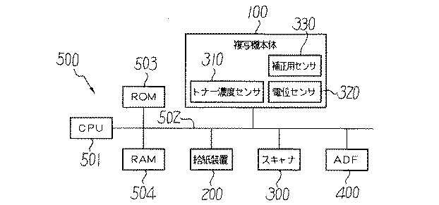
図6は本実施の形態の複写機が備える各部の電気的な接続を示すブロック図である。図6に示すように、本実施の形態の複写機には、コンピュータ構成のメイン制御部500が備えられており、このメイン制御部500が各部を駆動制御する。メイン制御部500は、各種演算や各部の駆動制御を実行するCPU(Central Processing Unit)501にバスライン502を介して、コンピュータプログラム等の固定的データを予め記憶するROM(Read Only Memory)503と各種データを書き換え自在に記憶するワークエリア等として機能するRAM(Random Access Memory)504とが接続されて構成されている。
FIG. 6 is a block diagram showing the electrical connection of each part provided in the copying machine of the present embodiment. As shown in FIG. 6, the copying machine of the present embodiment is provided with a
ROM503には、トナー濃度センサ310,補正用センサ330の出力値に対する単位面積当りのトナー付着量への換算に関する情報を記憶した換算テーブル(図示せず)が格納されている。
The
メイン制御部500には、複写機本体100の各部、給紙装置200、スキャナ300、原稿自動搬送装置400が接続されている。ここで、複写機本体100のトナー濃度センサ310、電位センサ320及び補正用センサ330は、検出した情報をメイン制御部500に送り出す。
Connected to the
次に、本実施の形態の複写機の動作について説明する。上記構成をもつ複写機を用いて原稿のコピーをとる場合、まず、原稿自動搬送装置400の原稿台30に原稿をセットする。または、原稿自動搬送装置400を開いてスキャナ300のコンタクトガラス31上に原稿をセットし、原稿自動搬送装置400を閉じてそれで押さえる。その後、ユーザーが図示しないスタートスイッチを押すと、原稿自動搬送装置400に原稿をセットしたときには、原稿がコンタクトガラス31上に搬送される。そして、スキャナ300が駆動して第1走行体33および第2走行体34が走行を開始する。これにより、第1走行体33からの光がコンタクトガラス31上の原稿で反射し、その反射光が第2走行体34のミラーで反射されて、結像レンズ35を通じて読取センサ36に案内される。このようにして原稿の画像情報を読み取る。
Next, the operation of the copying machine of this embodiment will be described. When copying a document using the copying machine having the above configuration, first, the document is set on the document table 30 of the
また、ユーザーによりスタートスイッチが押されると、図示しない駆動モータが駆動し、支持ローラ14,15,16のうちの1つが回転駆動して中間転写ベルト10が回転駆動する。また、これと同時に、各画像形成ユニット18Y,18C,18M,18Kの感光体ドラム20Y,20C,20M,20Kも回転駆動する。その後、スキャナ300の読取センサ36で読み取った画像情報に基づいて、露光装置21から、各画像形成ユニット18Y,18C,18M,18Kの感光体ドラム20Y,20C,20M,20K上に書込光がそれぞれ照射される。これにより、各感光体ドラム20Y,20C,20M,20Kには、それぞれ静電潜像が形成され、現像装置61Y,61C,61M,61Kにより可視像化される。そして、各感光体ドラム20Y,20C,20M,20K上には、それぞれ、イエロー、シアン、マゼンタ、ブラックのトナー像が形成される。
When the start switch is pressed by the user, a drive motor (not shown) is driven, and one of the
このようにして形成された各色トナー像は、各1次転写装置62Y,62C,62M,62Kにより、順次中間転写ベルト10上に重なり合うようにそれぞれ1次転写される。これにより、中間転写ベルト10上には、各色トナー像が重なり合った合成トナー像が形成される。なお、2次転写後の中間転写ベルト10上に残留した転写残トナーは、ベルトクリーニング装置17により除去される。
Each color toner image formed in this way is primarily transferred by the
また、ユーザーによりスタートスイッチが押されると、ユーザーが選択した転写紙5に応じた給紙装置200の給紙ローラ42が回転し、給紙カセット44の1つから転写紙5が送り出される。送り出された転写紙5は、分離ローラ45で1枚に分離して給紙路46に入り込み、搬送ローラ47により複写機本体100内の搬送路48まで搬送される。このようにして搬送された転写紙5は、レジストローラ49bに突き当たったところで止められる。なお、給紙カセット44にセットされていない転写紙5を使用する場合、手差しトレイ6にセットされた転写紙5を給紙ローラ50により送り出し、分離ローラ52で1枚に分離した後、手差し給紙路53を通って搬送される。そして、同じくレジストローラ49bに突き当たったところで止められる。
When the user presses the start switch, the
レジストローラ49bは、上述のようにして中間転写ベルト10上に形成された合成トナー画像が2次転写ローラ24に対向する2次転写部に搬送されるタイミングに合わせて回転を開始する。ここで、レジストローラ49bは、一般的には接地されて使用されることが多いが、転写紙5の紙粉除去のためにバイアスを印加するようにしてもよい。レジストローラ49bにより送り出された転写紙5は、中間転写ベルト10と2次転写ローラ24との間に送り込まれ、2次転写ローラ24により、中間転写ベルト10上の合成トナー像が転写紙5上に2次転写される。その後、転写紙5は、2次転写ローラ24に吸着した状態で定着装置25まで搬送され、定着装置25で熱と圧力が加えられてトナー像の定着処理が行われる。定着装置25を通過した転写紙5は、排出ローラ56により排紙トレイ7に排出されスタックされる。なお、トナー像が定着された面の裏面にも画像形成を行う場合には、定着装置25を通過した転写紙5の搬送方向を切替爪55により切り換え、用紙反転装置93に送り込む。転写紙5は、そこで反転し再び2次転写ローラ24に案内される。
The registration roller 49 b starts to rotate in accordance with the timing at which the composite toner image formed on the
次に、本実施の形態のCPU501がコンピュータプログラムに基づいて行う画像濃度制御であってセルフチェックである電位制御処理について図7ないし図17に基づいて説明する。ここで、図7は感光体ドラム20上のトナー付着量とセンサ出力との関係を示すグラフ、図8は感光体ドラム20の表面粗さとセンサ出力との関係を示すグラフ、図9は電位制御ルーチンを示すフローチャート、図10は感光体ドラム20上に形成するパッチパタンを説明する図、図11は中間転写ベルト10上に転写されるパッチパタンを示す平面図、図12はそのパッチパタンを示す拡大図、図15は電位制御時の電位データとトナー付着量データとの各パッチパタンにおける関係を示すグラフ、図16は電位制御時のトナー付着量データに対する電位データと制御電位データとの直線近似を示すグラフ、図17は電位制御テーブルを示す模式図である。
Next, potential control processing, which is image density control and self-check performed by the
電位制御処理は、トナー濃度センサ310の検出結果に基づいて電位制御を行う処理であるが、トナー濃度センサ310は様々な要因によりその出力特性が変わってしまうことがある。そこで、本実施の形態の電位制御処理では、補正用センサ330の検出結果に基づいてトナー濃度センサ310の検出結果を補正してその補正した検出結果を用いて処理を実行する。
The potential control process is a process for controlling the potential based on the detection result of the
ここで、トナー濃度センサ310の出力特性の変化について例を挙げて説明する。感光体ドラム20が新品の時、センサ特性は、図7においてラインaを示す。しかし、経時で感光体ドラム20の表面が荒れてくると、図8に示すように、感光体ドラム20の表面の光反射は拡散成分が増え、これによりトナー濃度センサ310のセンサ出力が高くなる。この結果、センサ出力特性は、図7においてラインbのような特性となる。本実施の形態の複写機においては、後述するように感光体ドラム20に対するトナー濃度センサ310の出力が一定になるようにVsg調整を定期的に行っているので、ラインbの特性は地肌出力がラインaと同等になるように調整される。このとき,トナー濃度センサ310の出力が低くなるようにトナー濃度センサ310のLED発光量を下げる調整が行われる為に、トナー濃度センサ310のセンサ出力特性は、図7においてラインcのような特性となる。この結果、同じセンサ出力に対して,その特性がラインa→ラインcのように変化する為、算出するトナー付着量が変わってくる。この変化が全色同時に起こればカラーバランスとしては大きく変化しないが、本実施の形態の複写機のように色毎に異なる感光体ドラム20を有する構成の場合は、それぞれの感光体ドラム20の表面の劣化の仕方も異なる。また、感光体ドラム20の表面の劣化の仕方が同じであるとしても、Vsg調整後電圧の色毎の誤差によっても、算出するトナー付着量が変わってくる。
Here, a change in the output characteristics of the
図9に示す電位制御のルーチンでは、基本的に、複写機の起動時、予め定められたコピー枚数の複写毎(つまり連続作像動作中における作像動作と作像動作との間)、一定時間毎等必要に応じて行うようになっている。ここでは起動時の実行動作について説明する。まず電源オン時の状態をジャム等の異常処理時と区別するために、ステップS701で電位制御の実行条件として定着装置25の定着温度を検出する。定着温度センサからの入力信号を基に、定着装置25の定着温度が100℃を越えているか否かを判断し、定着装置25の定着温度が100℃を越えている場合には(ステップS701のN)、異常と判定して電位制御を実行せずに処理を終了する。
In the potential control routine shown in FIG. 9, basically, at the time of starting the copying machine, a predetermined number of copies is made for each copy (that is, between the image forming operation and the image forming operation during the continuous image forming operation). This is done as needed, such as every hour. Here, the execution operation at the time of activation will be described. First, in order to distinguish the power-on state from an abnormal process such as a jam, the fixing temperature of the fixing
定着装置25の定着温度が100℃を越えていない場合には(ステップS701のY)、所定条件で一様に帯電された各感光体ドラム20の表面電位のチェックを電位センサ320により行い(ステップS702)、次に、ステップS703においてVsg調整を行う(ステップS703)。このVsg調整では、トナー濃度センサ310から感光体ドラム20の地肌部(表面)に対する出力値を取り込んでトナー濃度センサ310から感光体ドラム20の地肌部へ照射された光の反射光が一定値になるようにトナー濃度センサ310の発光量を調整する。ここでステップS702〜S703は各色の画像形成ユニット18で並列処理を行う。
If the fixing temperature of the fixing
ステップS704ではステップS702〜S703の処理において異常が無いかどうかチェックする。異常がある場合は(ステップS704のY)、ステップS718へ進み、エラーコードを設定して処理を終了する。 In step S704, it is checked whether there is any abnormality in the processing in steps S702 to S703. If there is an abnormality (Y in step S704), the process proceeds to step S718, an error code is set, and the process ends.
ステップS704において、ステップS702〜S703の処理において異常が無いと判断した場合には(ステップS704のY)、電位制御方式が自動に設定されているか、自動ではなく固定に設定されているかを判断する(ステップS705)。 If it is determined in step S704 that there is no abnormality in the processing in steps S702 to S703 (Y in step S704), it is determined whether the potential control method is set to automatic or fixed instead of automatic. (Step S705).
なお、先のステップS703〜S704では、電位制御方式に関わらず、他のトナー補給制御等で使用するためにステップS706に先立って動作を行ったものである。 In steps S703 to S704, the operation is performed prior to step S706 for use in other toner supply control regardless of the potential control method.
ステップS705で電位制御方式が自動ではなく固定であったと判断した場合は(ステップS705のN)、ステップS718でエラーコードを設定して処理を終了する。一方、ステップS705で電位制御方式が自動であったと判断した場合は(ステップS705のY)、ステップS706〜S707の処理を各色の画像形成ユニット18に対して並行して行う。
If it is determined in step S705 that the potential control method is not automatic but fixed (N in step S705), an error code is set in step S718, and the process ends. On the other hand, if it is determined in step S705 that the potential control method is automatic (Y in step S705), the processes in steps S706 to S707 are performed on the
ステップS706では、図5に示すように、各感光体ドラム20上にトナー像である基準トナーパッチとしてパッチパタン(潜像パタン)600を形成する。パッチパタン600は、感光体ドラム20の軸心90方向(幅方向)に対して色毎にずらして作像する。本実施の形態では、一つの色毎に例えば図10に示すようにN個の階調濃度を持つ静電潜像であるN個のパッチパタン600(600a,600b,600c・・・)を感光体ドラム20の回転方向に沿って所定の間隔で形成する。本実施の形態においては、16個の相異なる階調濃度を持つ各辺が15×20mmである矩形のパッチパタン600(600a,600b,600c・・・)を感光体ドラム20の回転方向に対して、10mmの間隔をおいて形成する。また、これらの色毎のパッチパタン600同士の感光体ドラム20の軸心90方向の間隔は、5mmに設定されている(図12参照)。このようにパッチパタン600同士を近接して形成して、それらの全体の幅をA6幅以内に収まるようにした。
In step S706, as shown in FIG. 5, a patch pattern (latent image pattern) 600 is formed on each
さらに、図5に示すように、これらのパッチパタン600に加えて、補正用の基準トナーであるパッチパタン601を各色毎に感光体ドラム20上に作像する。これらのパッチパタン601は、パッチパタン600に対して感光体ドラム20の軸心90方向にずれて形成される。詳しくは、パッチパタン601は、中間転写ベルト10に転写されたときに、感光体ドラム20の軸心90方向においてパッチパタン600Y,600C,600M,600Kが占める領域の外側に形成される。このときのパッチパタン600,601の感光体ドラム20の軸心方向の並びは、パッチパタン601、パッチパタン600Y,パッチパタン600C,パッチパタン600M,パッチパタン600Kである。なお、パッチパタン601の大きさやそれらの間隔はパッチパタン600と同様であり、パッチパタン601の作像条件は、パッチパタン600の作像条件と同じである。ここに、ステップS706によりトナーパッチ形成手段の機能が実行される。
Further, as shown in FIG. 5, in addition to these
このようにパッチパタン600,601を形成することにより、中間転写ベルト10にパッチパタン600,601が転写された際には、図11に示すように中間転写ベルト10上で各色のパッチパタン600,601が重なることなく形成される。ここで、図12に中間転写ベルト10上のパッチパタン600,601を拡大して示す。
By forming the
次のステップS707では、感光体ドラム20上のこれらのパッチパタン600の電位に対する電位センサ320の出力値を読み込んでRAM504に格納する。そして、感光体ドラム20上の4色分のパッチパタン600,601を並列動作で、黒現像装置61K、シアン現像装置61C、マゼンタ現像装置61M、イエロー現像装置61Yに現像させて顕像化させることにより各色のトナー像とする。
In the next step S 707, the output value of the
次いで、CPU501は、感光体ドラム20のパッチパタン600に対するトナー濃度センサ310によるトナーの濃度検出、及び、中間転写ベルト10に転写されたパッチパタン601に対する補正用センサによる濃度検出を行う(ステップS708)。このトナー濃度検出では、各色のトナー像であるパッチパタン600,601に対するトナー濃度センサ310,補正用センサ330の出力値を各色毎にVpi(i=1〜N)としてRAM504に格納する。
Next, the
次に、トナーの付着量を算出する(ステップS709)。すなわち、RAM504に格納したトナー濃度センサ310,補正用センサ330の出力値をROM503に格納されている換算テーブルを参照し、単位面積当りのトナー付着量に換算してRAM504に再び格納する。
Next, the toner adhesion amount is calculated (step S709). That is, referring to the conversion table stored in the
次に、ステップS709で算出したトナー濃度センサ310の検出値に基づく感光体ドラム20上のトナーの付着量を、補正用センサ330の検出値に基づいて補正する(ステップS710、補正手段)。まず、先に求めた感光体ドラム20上のトナー付着量(以後、ドラム上のトナー付着量ともいう)と、中間転写ベルト10上のトナー付着量(以後、ベルト上のトナー付着量ともいう)の関係は、4つのトナー濃度センサ310Y,310C,310M,310Kに対してそれぞれのトナー付着量の真値とのずれに相当する係数をA、感光体ドラム20から中間転写ベルト10へのトナーの転写率(%)をαとすると、次の式で示される。
ドラム上トナー付着量(K)=ベルト上トナー付着量(K)/α-----------(1)
ドラム上トナー付着量(M)=ベルト上トナー付着量(M)/α-----------(2)
ドラム上トナー付着量(C)=ベルト上トナー付着量(C)/α-----------(3)
ドラム上トナー付着量(Y)=ベルト上トナー付着量(Y)/α-----------(4)
Next, the toner adhesion amount on the
Amount of toner on drum (K) = Amount of toner on belt (K) / α ----------- (1)
Amount of toner on drum (M) = Amount of toner on belt (M) / α ----------- (2)
Toner adhesion amount on drum (C) = Toner adhesion amount on belt (C) / α ----------- (3)
Amount of toner on drum (Y) = Amount of toner on belt (Y) / α ----------- (4)
しかし、実際の検出結果にはそれぞれの検出誤差が加わる為、以下のようになる。ここで、補正用センサ330に対してそれぞれのトナー付着量真値とのずれに相当する係数をBとする。
ドラム上トナー付着量(K)×A(K)=ベルト上トナー付着量(K)×B(K)/α-----(5)
ドラム上トナー付着量(M)×A(M)=ベルト上トナー付着量(M)×B(M)/α-----(6)
ドラム上トナー付着量(C)×A(C)=ベルト上トナー付着量(C)×B(C)/α-----(7)
ドラム上トナー付着量(Y)×A(Y)=ベルト上トナー付着量(Y)×B(Y)/α-----(8)
However, since each detection error is added to the actual detection result, it is as follows. Here, a coefficient corresponding to a deviation from each true toner adhesion amount with respect to the
Amount of toner on drum (K) x A (K) = Amount of toner on belt (K) x B (K) / α ----- (5)
Amount of toner on drum (M) x A (M) = Amount of toner on belt (M) x B (M) / α ----- (6)
Amount of toner on drum (C) x A (C) = Amount of toner on belt (C) x B (C) / α ----- (7)
Amount of toner on drum (Y) x A (Y) = Amount of toner on belt (Y) x B (Y) / α ----- (8)
Bに関しては補正用センサ330が単一である為、色間での差は無いと言える。転写率αは本実施の形態においては、約95%である。そこでB=1として考えると、
ドラム上トナー付着量(K)×A(K)=ベルト上トナー付着量(K)/α---------(9)
ドラム上トナー付着量(M)×A(M)=ベルト上トナー付着量(M)/α---------(10)
ドラム上トナー付着量(C)×A(C)=ベルト上トナー付着量(C)/α---------(11)
ドラム上トナー付着量(Y)×A(Y)=ベルト上トナー付着量(Y)/α---------(12)
となる。
Regarding B, since the
Toner adhesion on drum (K) x A (K) = Toner adhesion on belt (K) / α --------- (9)
Amount of toner on drum (M) x A (M) = Amount of toner on belt (M) / α --------- (10)
Amount of toner on drum (C) x A (C) = Amount of toner on belt (C) / α --------- (11)
Amount of toner on drum (Y) x A (Y) = Amount of toner on belt (Y) / α --------- (12)
It becomes.
次に、これらの式を基にして、これまでに検出した感光体ドラム20上のトナー付着量と中間転写ベルト10上のトナー付着量とから、感光体ドラム20上のトナー付着量を補正した補正後トナー付着量を求める。まず、ブラック(K)を例に説明する。
Next, based on these formulas, the toner adhesion amount on the
ブラック(K)においては、トナーの高付着量部において、トナー濃度センサ310K、補正用センサ330の出力が飽和する為、トナーの低付着量域のデータを取るようにパッチパターン600,601の作像条件を設定し、作像する。このときのトナー濃度センサ310K、補正用センサ330の検出結果を表1に示す。この結果をグラフにすると図13のようになる。
In black (K), the output of the
ここで、A(K)=1.0497と求められる。 Here, A (K) = 1.0497 is obtained.
次に、マゼンタ(M)に関するトナー濃度センサ310M、補正用センサ330の検出結果を表2に示す。この結果をグラフにすると図14のようになる。
Next, Table 2 shows the detection results of the
ここでA(M)=1.025と求められる。同様にA(C)=1.057、A(Y)=1.002であった。 Here, A (M) = 1.025 is obtained. Similarly, A (C) = 1.057 and A (Y) = 1.002.
本実施の形態においては、上述した式(9)〜(12)を変形した次の式に基づいて、感光体ドラム20上のトナー付着量を算出する。
ドラム上トナー付着量(K)=ベルト上トナー付着量(K)/α/A(K)---------(13)
ドラム上トナー付着量(M)=ベルト上トナー付着量(M)/α/A(M)---------(14)
ドラム上トナー付着量(C)=ベルト上トナー付着量(C)/α/A(C)---------(15)
ドラム上トナー付着量(Y)=ベルト上トナー付着量(Y)/α/A(Y)---------(16)
In the present embodiment, the toner adhesion amount on the
Toner adhering amount on drum (K) = Toner adhering amount on belt (K) / α / A (K) --------- (13)
Toner adhesion amount on drum (M) = Toner adhesion amount on belt (M) / α / A (M) --------- (14)
Amount of toner on drum (C) = Amount of toner on belt (C) / α / A (C) --------- (15)
Toner adhesion amount on drum (Y) = Toner adhesion amount on belt (Y) / α / A (Y) --------- (16)
ベルト上トナー付着量を真値とすれば、補正後ドラム上トナー付着量は、次式によって求められる。
補正後ドラム上トナー付着量(K)=ドラム上トナー付着量(K)×α×A(K)---(17)
補正後ドラム上トナー付着量(M)=ドラム上トナー付着量(M)×α×A(M)---(18)
補正後ドラム上トナー付着量(C)=ドラム上トナー付着量(C)×α×A(C)---(19)
補正後ドラム上トナー付着量(Y)=ドラム上トナー付着量(Y)×α×A(Y)---(20)
If the toner adhesion amount on the belt is a true value, the corrected toner adhesion amount on the drum can be obtained by the following equation.
Amount of toner adhesion on drum after correction (K) = Amount of toner adhesion on drum (K) x α x A (K)-(17)
Toner adhering amount on drum after correction (M) = Toner adhering amount on drum (M) x α x A (M) --- (18)
Amount of toner adhering to drum after correction (C) = Amount of toner adhering to drum (C) x α x A (C) ---- (19)
Amount of toner adhesion on drum after correction (Y) = Amount of toner adhesion on drum (Y) x α x A (Y) --- (20)
例えば、感光体ドラム20上の(M)に対するトナー付着量検出結果が0.506であった場合、補正後の感光体ドラム20上のトナー付着量は式(18)に従い、0.506×1.025×0.95=0.493(mg/cm2)と求められる。
For example, when the toner adhesion amount detection result for (M) on the
ここで、補正の別の形態を説明する。この形態では、中間転写ベルト10上のカラートナー付着量検出の検出精度が低い場合を考慮し、カラーの付着量を(M)トナーを基準に設定する。これによってカラーの付着量検出バランスを保つ。具体的にはA(M)=1として考え、A(C)'=A(C)/A(M)=1.057/1.025=1.031、A(Y)'=A(Y)/A(M)=1.002/1.025=0.978となる。なお形態では色バランスに影響の少ない(K)の補正は行わない。
Here, another form of correction will be described. In this embodiment, in consideration of the case where the detection accuracy of the color toner adhesion amount detection on the
ここで、(M)の中間転写ベルト10上のトナー付着量を基準に考えると、補正後の感光体ドラム20上のトナー付着量は下式によって求められる。
補正後ドラム上トナー付着量(M)=ドラム上トナー付着量(M)×α×A(M)/A(M)-(21)
補正後ドラム上トナー付着量(C)=ドラム上トナー付着量(C)×α×A(C)/A(M)-(22)
補正後ドラム上トナー付着量(Y)=ドラム上トナー付着量(Y)×α×A(Y)/A(M)-(23)
Here, when the toner adhesion amount on the
Toner adhering amount on drum after correction (M) = Toner adhering amount on drum (M) x α x A (M) / A (M)-(21)
Toner adhering amount on drum after correction (C) = Toner adhering amount on drum (C) x α x A (C) / A (M)-(22)
Amount of toner adhesion on drum after correction (Y) = Amount of toner adhesion on drum (Y) x α x A (Y) / A (M)-(23)
例えば、感光体ドラム20上の(C)のトナー付着量検出結果が0.456であった場合、(C)の補正後ドラム上トナー付着量は式(22)に従い、0.456×1.031×0.95=0.447(mg/cm2)と求められる。
For example, when the toner adhesion amount detection result of (C) on the
このようにして上記2つの補正の方法などにより各色のトナー付着量を補正して算出した後、ステップS711〜S713を実行する。以下、これらのステップについて詳細に説明する。 In this way, after correcting and calculating the toner adhesion amount of each color by the above two correction methods, steps S711 to S713 are executed. Hereinafter, these steps will be described in detail.
ここで、図15はこれまでの処理で得られた感光体ドラム20上のパッチパタン600の電位データとトナー付着量データとの各パッチパタン600(600a,600b,600c・・・)における関係をX−Y平面上にプロットしたものである。X軸は電位ポテンシャル(現像バイアス電位VBと感光体ドラム20の表面電位との差)(単位V)を示し、Y軸は単位面積当りのトナー付着量(mg/cm2)を示している。本実施の形態においては、上述したように赤外光反射型センサのような光学方式のセンサでトナー濃度センサ310を構成しており、赤外光反射型センサは、一般的に、図15に示すように、トナー付着量が多い多付着部において飽和特性を示し、得られた検出値が実際のトナー付着量に対応しなくなる。このため、多付着部において得られたトナー濃度センサ310の検出値をそのまま用いてトナー付着量を算出してしまうと、実際の付着量とは異なった付着量を得ることになり、このトナー付着量を基に行うトナー補給制御を正確に行うことができなくなってしまう。
Here, FIG. 15 shows the relationship in the patch patterns 600 (600a, 600b, 600c,...) Between the potential data of the
そこで、本実施の形態におけるCPU501は、各色のパッチパタン600(600a,600b,600c・・・)毎に、電位センサ320とトナー濃度センサ310とから得られたパッチパタン600(600a,600b,600c・・・)の電位と、その顕像化後のトナー付着量のデータとを後述のように電位データXn(n=1〜10)とトナー付着量データYnとの関係(現像装置61の現像γ特性)の直線区間だけ選択し、この区間のデータに対して最小自乗法を適用することにより各現像装置61の現像特性の直線近似を後述するような方法によって行い、現像特性の近似直線方程式を各色毎に得、この近似直線方程式により各色毎に制御電位を計算するようにしている。
Therefore, the
最小自乗法の計算は次の式を用いる。
Xave=ΣXn/k---------(31)
Yave=ΣYn/k---------(32)
Sx=Σ(Xn−Xave)×(Xn−Xave)-----------(33)
Sy=Σ(Yn−Yave)×(Yn−Yave)-----------(34)
Sxy=Σ(Xn−Xave)×(Yn−Yave)---------(35)
電位センサ320とトナー濃度センサ310とから得られたパッチパタン600(600a,600b,600c・・・)の電位、顕像化後のトナー付着量のデータから求まる近似直線方程式をY=A1×X+B1としたとき、係数A1、B1は上記変数を用いて、
A1=Sxy/Sx------------------(36)
B1=Yave−A1×Xave------(37)
と表せる。
The following formula is used for the calculation of the least square method.
Xave = ΣXn / k -------- (31)
Yave = ΣYn / k --------- (32)
Sx = Σ (Xn-Xave) × (Xn-Xave) ---------- (33)
Sy = Σ (Yn-Yave) × (Yn-Yave) ---------- (34)
Sxy = Σ (Xn-Xave) × (Yn-Yave) -------- (35)
An approximate linear equation obtained from the data of the potential of the patch pattern 600 (600a, 600b, 600c...) Obtained from the
A1 = Sxy / Sx ------------------ (36)
B1 = Yave-A1 × Xave ----- (37)
It can be expressed.
また、近似直線方程式の相関係数Rは、
R×R=(Sxy×Sxy)/(Sx×Sy)---------(38)
と表わせる。本実施の形態では、CPU501は、ステップS709までにおいて、各色毎に電位センサ320とトナー濃度センサ310とから得られたパッチパタン600(600a,600b,600c・・・)の電位データXn、顕像化後のトナー付着量データYnの数値が若い方から5個のデータの組、
(X1〜X5、Y1〜Y5)
(X2〜X6、Y2〜Y6)
(X3〜X7、Y3〜Y7)
(X4〜X8、Y4〜Y8)
(X5〜X9、Y5〜Y9)
(X6〜X10、Y6〜Y10)
を取り出し、上述した式(31)〜(38)に従って直線近似計算を行うとともに、相関係数Rを算出して下記のような6組の近似直線方程式および相関係数(39)〜(44)を得る。
Y11=A11×X+B11;R11---------(39)
Y12=A12×X+B12;R12---------(40)
Y13=A13×X+B13;R13---------(41)
Y14=A14×X+B14;R14---------(42)
Y15=A15×X+B15;R15---------(43)
Y16=A16×X+B16;R16---------(44)
CPU501は、得られた6組の近似直線方程式のうちから相関係数R11〜R16内の最大値のものに対応する1組の近似直線方程式を近似直線方程式として選択する。
The correlation coefficient R of the approximate linear equation is
R × R = (Sxy × Sxy) / (Sx × Sy) -------- (38)
It can be expressed as In the present embodiment, until step S709, the
(X1-X5, Y1-Y5)
(X2-X6, Y2-Y6)
(X3-X7, Y3-Y7)
(X4 to X8, Y4 to Y8)
(X5 to X9, Y5 to Y9)
(X6-X10, Y6-Y10)
And performing linear approximation calculation according to the above equations (31) to (38) and calculating the correlation coefficient R to obtain the following six sets of approximate linear equations and correlation coefficients (39) to (44) Get.
Y11 = A11 × X + B11; R11 --------- (39)
Y12 = A12 × X + B12; R12 -------- (40)
Y13 = A13 × X + B13; R13 -------- (41)
Y14 = A14 × X + B14; R14 -------- (42)
Y15 = A15 × X + B15; R15 -------- (43)
Y16 = A16 × X + B16; R16 -------- (44)
The
次に、メイン制御部500(CPU501)は、ステップS711で、各色毎に上述の選択した近似直線方程式において、図16に示すようにYの値が必要最大トナー付着量Mmaxとなる時のXの値、すなわち現像ポテンシャルの値Vmaxを算出する。黒現像装置61K、シアン現像装置61C、マゼンタ現像装置61M、イエロー現像装置61Yの各現像バイアス電位VBと感光体ドラム20上の各色の画像露光による表面電位(露光電位)VLとは上述の式から次の式(45)、(46)で与えられる。
Vmax=(Mmax−B1)/A1--------------------(45)
VB−VL=Vmax=(Mmax−B1)/A1--------(46)
VBとVLとの関係は近似直線方式(E)の係数を用いて表わすことができる。したがって(46)式は、
Mmax=A1×Vmax+B1---------(47)
となる。
Next, in step S711, the main control unit 500 (CPU 501) uses the approximate linear equation selected for each color in the above-described approximate linear equation, as shown in FIG. 16, when the Y value becomes the required maximum toner adhesion amount Mmax. A value, that is, a development potential value Vmax is calculated. The developing bias potential VB of the black developing device 61K, the cyan developing device 61C, the magenta developing device 61M, and the yellow developing device 61Y and the surface potential (exposure potential) VL by image exposure of each color on the
Vmax = (Mmax-B1) / A1 ------ (45)
VB-VL = Vmax = (Mmax-B1) / A1 ------ (46)
The relationship between VB and VL can be expressed using the coefficient of the approximate linear method (E). Therefore, equation (46) is
Mmax = A1 * Vmax + B1 --------- (47)
It becomes.
ここで、感光体ドラム20の露光前の帯電電位VDと現像バイアス電位VBとの関係は、図16に示すような直線方程式、すなわち、
Y=A2*X+B2---------(48)
とX軸との交点のX座標VK(現像装置61の現像開始電圧)と、実験的に求めた地汚れ余裕電圧Vαとから、
VD−VB=VK+Vα---------(49)
で与えられる。
Here, the relationship between the charging potential VD before exposure of the
Y = A2 * X + B2 -------- (48)
From the X coordinate VK (development start voltage of the developing device 61) of the intersection of the X axis and the scumming margin voltage Vα obtained experimentally,
VD-VB = VK + Vα -------- (49)
Given in.
したがって、Vmax、VD、VB、VLの関係は、(46)、(49)式により決まる。この例ではVmaxを参照値として、これと各制御電圧VD、VB、VLの関係をあらかじめ実験等によって求め、図17に示すようにテーブル化して電位制御テーブルT1としてROM503に格納しておく。
Therefore, the relationship between Vmax, VD, VB, and VL is determined by the equations (46) and (49). In this example, using Vmax as a reference value, the relationship between this and each control voltage VD, VB, VL is obtained in advance through experiments or the like, tabulated as shown in FIG. 17, and stored in the
そして、CPU501はステップS712で、電位制御テーブルT1から各色毎に上記算出したVmaxに最も近いVmaxを選択し、その選択したVmaxに対応した各制御電圧(電位)VB、VD、VLを目標電位とする。
In step S712, the
次に、ステップS712で、露光装置21のレーザ制御部を介して半導体レーザのレーザ発光パワーを最大光量となるように制御し、電位センサ320の出力値を取り込むことにより感光体ドラム20の残留電位を検出する(ステップS713)。そして、ステップS714で、その残留電位が0でない時にはステップS712で決定した目標電位VB、VD、VLに対してその残留電位分の補正を行って目標電位とする。
Next, in step S712, the laser emission power of the semiconductor laser is controlled to the maximum light amount via the laser control unit of the
ステップS715では、以上のステップS705〜S714においてエラーが無いかどうか判断する。ここで1色でもエラーがあった場合は(ステップS715のN)、他の色だけ制御を行っても画像濃度変動が大きくなり、またこの後行うステップS716の動作が無駄になるために、エラーコードをセットして(ステップS718)、処理を終了する。この場合は作像条件は更新せず、次回セルフチェックが成功するまで前回と同じ作像条件で作像する。 In step S715, it is determined whether or not there is an error in steps S705 to S714. If there is an error even for one color (N in step S715), the image density fluctuation becomes large even if only the other colors are controlled, and the operation in step S716 to be performed thereafter is wasted. A code is set (step S718), and the process ends. In this case, the image forming conditions are not updated, and image forming is performed under the same image forming conditions as before until the next self-check is successful.
ステップS715において、エラー無しと判断した場合は(ステップS715のY)、ステップS716で、各色並行して感光体ドラム20の帯電装置60による帯電電位VDが上記目標電位になるように電源回路(図示せず)を調整し、レーザ制御部(図示せず)を介して半導体レーザにおけるレーザ発光パワーを感光体ドラム20の表面電位VLが上記目標電位になるように調整し、かつ、黒現像装置61K、シアン現像装置61C、マゼンタ現像装置61M、イエロー現像装置61Yの各現像バイアス電位VBがそれぞれ上記目標電位になるように電源回路を調整する(画像濃度制御手段)。
If it is determined in step S715 that there is no error (Y in step S715), in step S716, a power supply circuit (FIG. 5) is arranged so that the charging potential VD by the charging
そして、ステップS717では、ステップS716でエラーが有ったか否かを判断する。ステップS716でエラーが無かった場合には(ステップS717のY)、処理を終了する。一方、ステップS716でエラーが有った場合には(ステップS717のN)、ステップS718へ進みエラーコードを設定して処理を終了する。 In step S717, it is determined whether or not there is an error in step S716. If there is no error in step S716 (Y in step S717), the process ends. On the other hand, if there is an error in step S716 (N in step S717), the process proceeds to step S718, an error code is set, and the process is terminated.
このような電位制御は画像品質を一定に維持するために特にカラー画像形成装置においては重要な制御である。 Such potential control is an important control particularly in a color image forming apparatus in order to maintain a constant image quality.
以上説明したように、本実施の形態においては、複数の感光体ドラム20毎に設けられたトナー濃度センサ310Y,310C,310M,310Kの検出特性が異なっても、それらの検出結果が中間転写ベルト10上のトナー濃度を検出する補正用センサ330の検出結果により補正されるので、複数のトナー濃度センサ310Y,310C,310M,310Kの検出特性の違いなどに起因する画像濃度不良の発生を防止することができ、画像濃度の安定した複写機を提供することができる。これにより、環境が変化しても経時にわたって画像濃度の安定した複写機を提供することができる。
As described above, in the present exemplary embodiment, even if the detection characteristics of the
また、本実施の形態においては、画像濃度制御である電位制御を実行するための各感光体ドラム20に対応するパッチパタン600が図11に示すように、中間転写ベルト10上に互いにずれて転写されるので、ベルトクリーニング装置17、ローラクリーニング部91に対してかかる負荷が軽くなるので、それらでのクリーニング不良や、各転写工程での転写散りによるトナー飛散が発生することを防止することができる。また、各感光体ドラム20上に並行して各色のパッチパタン600の形成ができるので、電位制御を実行する際のユーザーの待ち時間を短縮することができる。
In the present embodiment, the
また、本実施の形態においては、パッチパタン600と、パッチパタン601とを並行して作像することができ、これにより、パッチパタン600の作成を伴う電位制御等の画像濃度制御を実行する際のユーザーの待ち時間を短縮することができる。
Further, in the present embodiment, the
また、本実施の形態においては、同じ作像条件のパッチパタン600,601同士に基づいてトナー濃度の補正を行うので、補正精度を高くすることができる。
In the present embodiment, the toner density is corrected based on the
また、本実施の形態においては、ブラック(K)に対応するトナー濃度センサ310Kが他のトナー濃度センサ310Y,310C,310Mよりも補正用センサ330から遠い位置に配置されているので、つまり、ブラック(K)のトナーに比較して色変動に寄与の大きいその他のカラー(Y,C,M)トナーに対応するトナー濃度センサ310Y,310C,310Mと、補正用センサ330との位置関係が、ブラック(K)に対応するトナー濃度センサ310Kと補正用センサ330との位置関係に比べて近くなるので、これにより、パッチパタン600,601の作像位置による差を少なくして補正精度を高めることができる。
In the present embodiment, the
また、本実施の形態においては、各色のパッチパタン600全体がA6幅以内に収まるようにしたので、通常出力される画像はA6幅以上であるため、これによって各色のパッチパタン600位置における変動が少なく、検出位置による色毎の検出誤差が少なくなり、高速で精度の高い複写機を提供することができる。
In the present embodiment, since the
なお、本実施の形態では、画像濃度制御である電位制御処理において、4色に対して電位センサ320、トナー濃度センサ310の出力を並列に処理するために、各チャンネルで独立したサンプリング周期4msecのA/Dを採用している。
In the present embodiment, in the potential control process that is the image density control, the outputs of the
また、本実施の形態は、画像形成装置として複写機を例に説明したが、これに限るものではなく、プリンタなどであってもよい。 In this embodiment, the copying machine is described as an example of the image forming apparatus. However, the present invention is not limited to this, and a printer or the like may be used.
10 中間転写ベルト(中間転写体)
20 感光体ドラム(像担持体)
90 軸心
310 トナー濃度センサ(第1の検出器)
330 補正用検出器(第2の検出器)
600,601 パッチパタン(基準トナーパッチ)
S706 トナーパッチ形成手段
S710 補正手段
S716 画像濃度制御手段
10 Intermediate transfer belt (intermediate transfer member)
20 Photosensitive drum (image carrier)
90
330 Detector for correction (second detector)
600, 601 Patch pattern (reference toner patch)
S706 Toner patch forming means S710 Correction means S716 Image density control means
Claims (5)
前記像担持体毎に前記像担持体に対向して設けられ、対向する前記像担持体に形成されたトナー像の濃度を光学的に検出する複数の第1の検出器と、
前記中間転写体に対向して設けられ、前記中間転写体に転写されたトナー像の濃度を光学的に検出する第2の検出器と、
トナー像である基準トナーパッチを各前記像担持体上に形成し中間転写体に転写させるトナーパッチ形成手段と、
前記第2の検出器の検出結果に基づいて前記第1の検出器の検出結果を補正する補正手段と、
補正された前記第1の検出器の検出結果に基づいて画像濃度制御を実行する画像濃度制御手段と、
を備えることを特徴とする画像形成装置。 In an image forming apparatus that obtains a color image by transferring a toner image formed by electrophotography on a plurality of rotationally driven image carriers to an intermediate transfer member,
A plurality of first detectors that are provided to face the image carrier for each image carrier and optically detect the density of a toner image formed on the opposite image carrier;
A second detector provided opposite to the intermediate transfer member and optically detecting the density of the toner image transferred to the intermediate transfer member;
A toner patch forming means for forming a reference toner patch, which is a toner image, on each of the image carriers and transferring it to an intermediate transfer member;
Correction means for correcting the detection result of the first detector based on the detection result of the second detector;
Image density control means for performing image density control based on the corrected detection result of the first detector;
An image forming apparatus comprising:
前記トナーパッチ形成手段は、前記第1の検出器の配置に合わせて前記基準トナーパッチを形成する、ことを特徴とする請求項1記載の画像形成装置。 At least two of the first detectors are arranged offset from each other in the axial direction of the image carrier;
The image forming apparatus according to claim 1, wherein the toner patch forming unit forms the reference toner patch in accordance with an arrangement of the first detector.
前記トナーパッチ形成手段は、前記第1及び第2の検出器の配置に合わせて前記基準トナーパッチを形成する、ことを特徴とする請求項1又は2記載の画像形成装置。 The second detector is arranged so as to be shifted in the axial direction of the image carrier with respect to all the first detectors,
The image forming apparatus according to claim 1, wherein the toner patch forming unit forms the reference toner patch in accordance with an arrangement of the first and second detectors.
黒色のトナー像が形成される前記像担持体に対応する前記第1の検出器と前記第2の検出器とは、全ての前記第1の検出器と前記第2の検出器とのうちで前記像担持体の軸心方向において最も離れた位置に配置されている、ことを特徴とする請求項1,2,3又は4記載の画像形成装置。
The image carrier is provided for each of a plurality of toner colors including black,
The first detector and the second detector corresponding to the image carrier on which a black toner image is formed are among all the first detectors and the second detectors. The image forming apparatus according to claim 1, wherein the image forming apparatus is disposed at a position farthest in the axial direction of the image carrier.
Priority Applications (2)
| Application Number | Priority Date | Filing Date | Title |
|---|---|---|---|
| JP2003328751A JP4280588B2 (en) | 2003-09-19 | 2003-09-19 | Image forming apparatus |
| US10/864,524 US7190912B2 (en) | 2003-06-12 | 2004-06-10 | Tandem type color image forming apparatus |
Applications Claiming Priority (1)
| Application Number | Priority Date | Filing Date | Title |
|---|---|---|---|
| JP2003328751A JP4280588B2 (en) | 2003-09-19 | 2003-09-19 | Image forming apparatus |
Publications (2)
| Publication Number | Publication Date |
|---|---|
| JP2005092118A JP2005092118A (en) | 2005-04-07 |
| JP4280588B2 true JP4280588B2 (en) | 2009-06-17 |
Family
ID=34458231
Family Applications (1)
| Application Number | Title | Priority Date | Filing Date |
|---|---|---|---|
| JP2003328751A Expired - Fee Related JP4280588B2 (en) | 2003-06-12 | 2003-09-19 | Image forming apparatus |
Country Status (1)
| Country | Link |
|---|---|
| JP (1) | JP4280588B2 (en) |
Families Citing this family (3)
| Publication number | Priority date | Publication date | Assignee | Title |
|---|---|---|---|---|
| JP4786979B2 (en) * | 2005-09-14 | 2011-10-05 | 株式会社リコー | Image forming apparatus |
| JP5050589B2 (en) * | 2007-03-15 | 2012-10-17 | 富士ゼロックス株式会社 | Recording medium, image forming apparatus, image defect position determining apparatus, image forming program, and image defect position determining program |
| JP5262671B2 (en) * | 2008-12-16 | 2013-08-14 | 株式会社リコー | Image forming apparatus and image forming method |
-
2003
- 2003-09-19 JP JP2003328751A patent/JP4280588B2/en not_active Expired - Fee Related
Also Published As
| Publication number | Publication date |
|---|---|
| JP2005092118A (en) | 2005-04-07 |
Similar Documents
| Publication | Publication Date | Title |
|---|---|---|
| JP5268020B2 (en) | Image forming apparatus | |
| US9134656B2 (en) | Image forming apparatus | |
| JP5279224B2 (en) | Image forming apparatus | |
| JP4027287B2 (en) | Image forming apparatus | |
| JP5376332B2 (en) | Image forming apparatus | |
| JP6137615B2 (en) | Image forming apparatus and image density control method | |
| JP2009116130A (en) | Image forming apparatus | |
| US8301047B2 (en) | Image forming apparatus and method of controlling development electric field strength therein | |
| JP2009294525A (en) | Image forming apparatus | |
| JP2008191214A (en) | Image forming apparatus | |
| JP2008040441A (en) | Image forming apparatus | |
| JP4280588B2 (en) | Image forming apparatus | |
| JP4520181B2 (en) | Image forming apparatus | |
| JP2018120219A (en) | Image forming apparatus | |
| JP2007101755A (en) | Image forming apparatus | |
| JP2005148281A (en) | Image forming apparatus | |
| JP2001324846A (en) | Image forming device | |
| JP2000147849A (en) | Image forming device | |
| JP2003076101A (en) | Image forming apparatus | |
| JP2004013033A (en) | Image forming apparatus | |
| JP2005275119A (en) | Image forming apparatus | |
| JP5317497B2 (en) | Image forming apparatus | |
| JP6032519B2 (en) | Image forming apparatus | |
| JP7240600B2 (en) | image forming device | |
| JP2013057759A (en) | Color image forming apparatus |
Legal Events
| Date | Code | Title | Description |
|---|---|---|---|
| RD01 | Notification of change of attorney |
Free format text: JAPANESE INTERMEDIATE CODE: A7421 Effective date: 20051021 |
|
| A621 | Written request for application examination |
Free format text: JAPANESE INTERMEDIATE CODE: A621 Effective date: 20060807 |
|
| RD01 | Notification of change of attorney |
Free format text: JAPANESE INTERMEDIATE CODE: A7421 Effective date: 20060810 |
|
| A977 | Report on retrieval |
Free format text: JAPANESE INTERMEDIATE CODE: A971007 Effective date: 20090219 |
|
| TRDD | Decision of grant or rejection written | ||
| A01 | Written decision to grant a patent or to grant a registration (utility model) |
Free format text: JAPANESE INTERMEDIATE CODE: A01 Effective date: 20090227 |
|
| A01 | Written decision to grant a patent or to grant a registration (utility model) |
Free format text: JAPANESE INTERMEDIATE CODE: A01 |
|
| A61 | First payment of annual fees (during grant procedure) |
Free format text: JAPANESE INTERMEDIATE CODE: A61 Effective date: 20090316 |
|
| FPAY | Renewal fee payment (event date is renewal date of database) |
Free format text: PAYMENT UNTIL: 20120319 Year of fee payment: 3 |
|
| R150 | Certificate of patent or registration of utility model |
Free format text: JAPANESE INTERMEDIATE CODE: R150 |
|
| FPAY | Renewal fee payment (event date is renewal date of database) |
Free format text: PAYMENT UNTIL: 20120319 Year of fee payment: 3 |
|
| FPAY | Renewal fee payment (event date is renewal date of database) |
Free format text: PAYMENT UNTIL: 20130319 Year of fee payment: 4 |
|
| FPAY | Renewal fee payment (event date is renewal date of database) |
Free format text: PAYMENT UNTIL: 20140319 Year of fee payment: 5 |
|
| LAPS | Cancellation because of no payment of annual fees |