JP4323624B2 - Sheet processing apparatus, control method, and image forming apparatus - Google Patents
Sheet processing apparatus, control method, and image forming apparatus Download PDFInfo
- Publication number
- JP4323624B2 JP4323624B2 JP20607499A JP20607499A JP4323624B2 JP 4323624 B2 JP4323624 B2 JP 4323624B2 JP 20607499 A JP20607499 A JP 20607499A JP 20607499 A JP20607499 A JP 20607499A JP 4323624 B2 JP4323624 B2 JP 4323624B2
- Authority
- JP
- Japan
- Prior art keywords
- sheet
- unit
- image
- processing
- inserter
- Prior art date
- Legal status (The legal status is an assumption and is not a legal conclusion. Google has not performed a legal analysis and makes no representation as to the accuracy of the status listed.)
- Expired - Fee Related
Links
Images


Classifications
-
- G—PHYSICS
- G03—PHOTOGRAPHY; CINEMATOGRAPHY; ANALOGOUS TECHNIQUES USING WAVES OTHER THAN OPTICAL WAVES; ELECTROGRAPHY; HOLOGRAPHY
- G03G—ELECTROGRAPHY; ELECTROPHOTOGRAPHY; MAGNETOGRAPHY
- G03G15/00—Apparatus for electrographic processes using a charge pattern
- G03G15/65—Apparatus which relate to the handling of copy material
- G03G15/6538—Devices for collating sheet copy material, e.g. sorters, control, copies in staples form
- G03G15/6541—Binding sets of sheets, e.g. by stapling, glueing
-
- B—PERFORMING OPERATIONS; TRANSPORTING
- B65—CONVEYING; PACKING; STORING; HANDLING THIN OR FILAMENTARY MATERIAL
- B65H—HANDLING THIN OR FILAMENTARY MATERIAL, e.g. SHEETS, WEBS, CABLES
- B65H7/00—Controlling article feeding, separating, pile-advancing, or associated apparatus, to take account of incorrect feeding, absence of articles, or presence of faulty articles
-
- G—PHYSICS
- G03—PHOTOGRAPHY; CINEMATOGRAPHY; ANALOGOUS TECHNIQUES USING WAVES OTHER THAN OPTICAL WAVES; ELECTROGRAPHY; HOLOGRAPHY
- G03G—ELECTROGRAPHY; ELECTROPHOTOGRAPHY; MAGNETOGRAPHY
- G03G15/00—Apparatus for electrographic processes using a charge pattern
- G03G15/65—Apparatus which relate to the handling of copy material
- G03G15/6582—Special processing for irreversibly adding or changing the sheet copy material characteristics or its appearance, e.g. stamping, annotation printing, punching
-
- B—PERFORMING OPERATIONS; TRANSPORTING
- B65—CONVEYING; PACKING; STORING; HANDLING THIN OR FILAMENTARY MATERIAL
- B65H—HANDLING THIN OR FILAMENTARY MATERIAL, e.g. SHEETS, WEBS, CABLES
- B65H2511/00—Dimensions; Position; Numbers; Identification; Occurrences
- B65H2511/20—Location in space
- B65H2511/24—Irregularities, e.g. in orientation or skewness
-
- B—PERFORMING OPERATIONS; TRANSPORTING
- B65—CONVEYING; PACKING; STORING; HANDLING THIN OR FILAMENTARY MATERIAL
- B65H—HANDLING THIN OR FILAMENTARY MATERIAL, e.g. SHEETS, WEBS, CABLES
- B65H2513/00—Dynamic entities; Timing aspects
- B65H2513/40—Movement
-
- B—PERFORMING OPERATIONS; TRANSPORTING
- B65—CONVEYING; PACKING; STORING; HANDLING THIN OR FILAMENTARY MATERIAL
- B65H—HANDLING THIN OR FILAMENTARY MATERIAL, e.g. SHEETS, WEBS, CABLES
- B65H2513/00—Dynamic entities; Timing aspects
- B65H2513/50—Timing
- B65H2513/51—Sequence of process
Description
【0001】
【発明の属する技術分野】
画像形成されたシートを積載するシート処理装置及び画像形成装置等に関する。
【0002】
【従来の技術】
従来、記録紙の先頭頁、最終頁、または、途中頁に、通常の記録紙とは別のシート(以下、特殊シート)を挿入する表紙モード、合紙モード等のモードを備えた複写装置がある。これらのモードを複写装置の操作部でユーザが設定することで、例えば、色の違う用紙やカラーコピー紙を表紙として挿入したり、任意の枚数毎に仕切り紙として挿入することが出来る。
【0003】
特殊シートの供給方法としては、複写装置本体側に設けられた特別のカセットから供給したり、特殊シートを供給する為の給紙部をフィニッシャ等のシート処理装置側に設け、該給紙部から特殊シートを供給する方法が提案されている。また、該給紙部から搬送される特殊シートに対してステイプル処理や穴あけ処理を行えるようにすることが提案されている。
【0004】
【発明が解決しようとする課題】
しかしながら、給紙部や特別のカセット等から搬送される特殊シートの斜行に対する十分な対策が成されていなかった為に、上記給紙部や特別のカセット等から特殊シートが斜行した状態で搬送されてしまった場合、搬送途中で紙詰まりが生じたり、例えば、穴あけ処理等がシート上の所望する位置に行われていない等の不具合が生じる可能性があり、これにより、ユーザが再度同一のシートを用意しなければならないといった不具合が生じ、ユーザに対する余計な手間や労力が増え、コスト高となる虞があった。
【0005】
【課題を解決するための手段】
上記問題を解決するため、本発明は、画像形成装置に接続可能であって、シートを積載する第1の積載手段と、前記第1の積載手段に積載されたシート及び前記画像形成装置により画像形成されたシートを搬送する搬送手段と、
前記搬送手段により搬送された前記第1の積載手段からのシート及び前記画像形成装置からのシートを積載する第2の積載手段とを有し、前記画像形成装置の動作モードに応じて前記搬送手段により搬送される前記第1の積載手段からのシート及び前記画像形成装置からのシートに対してシート加工処理が可能なシート処理装置において、前記第1の積載手段から搬送されるシートの斜行量を検出する検出手段と、前記シート加工処理を行うか否かを判定する判定手段と、前記検出手段により検出したシートの斜行量および前記判定手段による判定結果に基づいて、前記搬送手段によるシートの搬送を制御する制御手段と、を有し、前記制御手段は、前記検出手段により検出したシートの斜行量が第1の斜行量を越え、前記判定手段により前記シート加工処理を行うと判定した場合は、前記搬送手段によるシートの搬送動作を停止し、前記検出手段により検出したシートの斜行量が第1の斜行量を越え、前記判定手段により前記シート加工処理を行わないと判定した場合は、前記搬送手段によるシートの搬送動作を継続することを特徴とするシート処理装置を提供するものである。
【0008】
【発明の実施の形態】
図1は、本発明の実施形態である複写装置1000の内部構造を示す断面図である。複写装置1000は、原稿給送部100、イメージリーダ部200及びプリンタ部300、折り処理部400、フィニッシャ500、インサータ900を有する。
【0009】
図1を参照して、原稿給送部100のトレイ1001上には、ユーザから見て正立状態で、且つ、フェイスアップ状態(画像が形成されている面が上向きの状態)で原稿がセットされているものとし、原稿の綴じ位置は、原稿の左端部に位置するものとする。トレイ1001上にセットされた原稿は、原稿給送部100により先頭頁から順に1枚ずつ左方向(図の矢印方向)、即ち、綴じ位置を先端にして搬送される。そして、更に該原稿は、湾曲したパスを介してプラテンガラス102上を左方向から右方向へ搬送され、その後排紙トレイ112上に排出される。尚、この際、スキャナユニット104は、所定の位置に保持された状態にあり、該スキャナユニット104上を原稿が左から右へと通過することにより原稿の読取処理が行われる。上述した読み取り方法を原稿流し読みとする。原稿がプラテンガラス102上を通過する際、該原稿は、スキャナユニット104のランプ103により照射され、その原稿からの反射光がミラー105,106,107、レンズ108を介してイメージセンサ109に導かれる。
【0010】
尚、原稿給送部100により搬送した原稿をプラテンガラス102上に一旦停止させ、その状態でスキャナユニット104を左から右へと移動させることにより原稿の読取処理を行うことも出来る。この読み取り方法を原稿固定読みとする。原稿給送部100を使用しないで原稿の読み取りを行わせる場合、ユーザは、原稿給送部100を持ち上げ、プラテンガラス102上に原稿をセットする。この場合、上述した原稿固定読みが行なわれる。
【0011】
イメージセンサ109により読み取られた原稿の画像データは、所定の画像処理が施されて露光制御部110へ送られる。露光制御部110は、画像信号に応じたレーザ光を出力する。該レーザ光は、ポリゴンミラー110aにより走査されながら感光ドラム111上に照射される。感光ドラム111上には走査されたレーザ光に応じた静電潜像が形成される。
【0012】
感光ドラム111上に形成された静電潜像は、現像器113により現像され、トナー像として可視化される。一方、記録紙は、カセット114、115、手差し給紙部125、両面搬送パス124の何れかから転写部116へ搬送される。そして、可視化されたトナー像が転写部116において記録紙に転写される。転写後の記録紙は、定着部117にて定着処理が施される。
【0013】
そして、定着部117を通過した記録紙をフラッパ121により一旦パス122に導き、記録紙の後端がフラッパ121を抜けた後に、スイッチバックさせ、フラッパ121により排出ローラ118へ搬送する。そして、排出ローラ118により該記録紙をプリンタ部300から排出する。これによりトナー像が形成された面を下向きの状態(フェイスダウン)でプリンタ部300から排出できる。これを反転排紙と称する。
【0014】
上述したようにフェイスダウンで記録紙を機外に排出することにより、先頭頁から順に画像形成処理を行う場合、例えば、原稿給送部100を使用して画像形成処理を行う場合や、コンピュータからの画像データに対する画像形成処理を行う場合に頁順序を揃えることが出来る。
【0015】
尚、手差し給紙部125から搬送するOHPシート等の硬いシートに対して画像形成処理を行う場合は、パス122に該シートを導くことなく、トナー像が形成された面を上向きの状態(フェイスアップ)で排出ローラ118によりプリンタ部300から排出する。
【0016】
また、シートの両面に画像形成処理を行う場合は、シートを定着部117からまっすぐ排出ローラ118方向へと導き、シートの後端がフラッパ121を抜けた直後にシートをスイッチバックし、フラッパ121により両面搬送パスへと導く。
【0017】
次に、原稿固定読みの場合と原稿流し読みの場合の夫々の場合における画像形成処理方法について図2を参照しながら説明を行う。
【0018】
原稿固定読みの場合、スキャナユニット104を左から右へ走査することにより原稿の画像を走査する。即ち、図2(a)に示すように、原稿画像に対して、主走査方向をSy、副走査方向をSxとする読み取り走査が行なわれ、イメージセンサ109により原稿の画像が読み取られる。そして、イメージセンサ109により読み取られた画像に関しては、主走査方向Syに読み取った画像を露光制御部110で順次レーザ光に変換し、該レーザ光をポリゴンミラー110aで走査(図の矢印方向に走査)することにより感光ドラム111上に静電潜像を形成する。
【0019】
このようにして形成された静電潜像をトナー像として可視化して、シート上に該トナー像を形成すると、シート上には、鏡像ではない正像画像(非鏡像画像)が形成される。
【0020】
一方、原稿流し読みの場合、図2(b)に示すように、原稿画像に対して、主走査方向をSy、副走査方向Sxとする読み取り走査が行なわれ、イメージセンサ109により画像が読み取られる。原稿流し読みの時は、原稿が左から右に向けて搬送されるので、副走査方向に関しては、原稿固定読み時の副走査方向と逆の方向となる。従って、イメージセンサ109により読み取られた画像は、原稿画像に対して鏡像となるので、該鏡像を正像画像に修正する必要がある。そこで、原稿流し読みの場合は、イメージセンサ109にて読み取った画像を正像画像にする為の鏡像処理を行う。鏡像処理では、主走査方向を逆方向に入れ替える処理として、主走査方向の一方の向きに対して読み取った画像を、その主走査方向の一方の向きに対して逆向きに反転させるよう処理する。
【0021】
即ち、本形態の鏡像処理とは、図2(b)に示すように、読み取った画像を180度回転させて出力する為の処理であって、入力された画像を180度回転させる回転処理を本形態では、鏡像処理と呼ぶ。
【0022】
該鏡像処理によりイメージセンサ109で読み取った画像は、正像画像に変換され、感光ドラム111上には、鏡像処理後の静電潜像が形成される。このようにして形成された静電潜像をトナー像として可視化して、シート上に該トナー像を形成すると、シート上には、鏡像ではない正像画像が形成される。更に、該画像が形成されたシートを反転排紙することにより、トナー像が形成された面を下に向けた状態で機外(プリンタ部300)から排出することが出来る。そして、該反転排紙により排出されたシートの後端側を後述するフィニッシャ500のステイプラ601で綴じれば、画像が形成された面からシートを見た場合に、該画像に対してシートの左側を綴じることが出来る。
【0023】
尚、副走査方向を逆方向に入れ替えることにより鏡像処理を行うことも出来るが、この場合、原稿1頁分の画像の読取処理が終了しないと鏡像処理を行えないことや、反転排紙後の後端綴じにより画像に対してシートの左端側を綴じることを考慮すると主走査方向の入れ替えることによる鏡像処理が好ましい。
【0024】
図1を参照して、排出ローラ118によりプリンタ部300から排出されたシートは折り処理部400へ送り込まれる。折り処理部400では、シートをZ形に折りたたむように折り処理が行われる。例えば、A3サイズやB4サイズのシートで且つ折り処理の指定が操作部よりなされている場合は、プリンタ部300より排出されたシートに対して折り処理が行なわれる。一方それ以外の場合は、プリンタ部300から排出されたシートに対して折り処理を行うこと無く、そのままフィニッシャ500へと送り込む。
【0025】
該フィニッシャ500上には、インサータ900が設けられている。インサータ900は、記録紙の先頭頁、最終頁、または、途中頁に、通常の記録紙とは別のシートを挿入する為のものであり、プリンタ部300にて画像が形成されたシートとシートの間に合紙や表紙用のシートを挿入する為のものである。フィニッシャ本体500では、プリンタ部300から搬送されたシートやインサータ900からのシートを含んだシート束に対する製本処理や綴じ処理、穴あけ処理等の処理が行われる。
【0026】
図3は、複写装置1000のブロック図である。CPU回路部150は、CPU(不図示)を有し、ROM151に格納された制御プログラム及び操作部1の設定に従がい、原稿給送制御部101、イメージリーダ制御部201、画像信号制御部202、プリンタ制御部301、折り処理制御部401、フィニッシャ制御部501、外部I/F203を制御する。そして、原稿給送制御部101は原稿給送部100を、イメージリーダ制御部201はイメージリーダ部200を、プリンタ制御部301はプリンタ部300を、折り処理制御部401は折り処理部400を、フィニッシャ制御部501はフィニッシャ500を制御する。操作部1は、画像形成に関する各種機能を設定する為の複数のキー、設定状態を表示する為の表示部等を有し、ユーザによる各キーの操作に対応するキー信号をCPU回路部150に出力すると共に、CPU回路部150からの信号に基づき対応する情報を表示部に表示する。
【0027】
RAM152は、制御データを一時的に保持する為の領域や、制御に伴う演算の作業領域として用いられる。外部I/F203は、複写装置1000と外部のコンピュータ204とのインタフェースであり、コンピュータ204からのプリントデータをビットマップ画像に展開し、画像データとして画像信号制御部202へ出力する。また、イメージリーダ制御部201から画像信号制御部202へは、イメージセンサ209で読み取った原稿の画像が出力される。プリンタ制御部301は、画像信号制御部202からの画像データを露光制御部110へ出力する。
【0028】
図4は、画像信号制御部202の詳細な説明を行う為のブロック図である。画像信号制御部202は、画像処理部203、ラインメモリ204、ページメモリ205、ハードディスク206を有する。画像処理部203では、画像の補正処理や操作部1からの設定に従がい編集処理を行う。ラインメモリ204では、上述した、主走査方向を入れ替える処理即ち鏡像処理が行なわれる。ラインメモリ204から出力された画像は、ページメモリ205を介して、プリンタ制御部301へ入力される。尚、ハードディスク206は、頁順を入れ替える処理、即ち電子ソート等に使用される。
【0029】
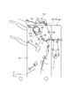
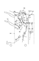
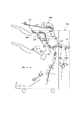
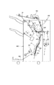
次に、折り処理部400及びフィニッシャ500の構成について、図5を参照しながら説明する。図5は、図1の折り処理部400及びフィニッシャ500の構成を示す図である。
【0030】
折り処理部400は、プリンタ部300から排出されたシートを導入し、フィニッシャ500側に導く為の搬送パス402を有する。搬送パス402上には、搬送ローラ対403及び404が設けられている。また、搬送ローラ対404の近傍に設けられた切替フラッパ410は、搬送ローラ対403により搬送されたシートを折りパス420またはフィニッシャ側500に導く為のものである。
【0031】
折り処理を行う場合、切替フラッパ410を折りパス420側に切り替え、シートを折りパス420に導く。折りパス420に導かれたシートは、折りローラ421まで搬送され、Z型に折り畳まれる。一方、折り処理を行わない場合は、切替フラッパ410をフィニッシャ側500に切り換え、プリンタ部300から排出されたシートを搬送パス402を介して、直接送り込む。
【0032】
フィニッシャ500の構成について説明する。フィニッシャ500は、折り処理部400を介して搬送されたプリンタ部300からのシートを取り込み、取り込んだ複数のシートを整合して1つのシート束として束ねる処理、シート束の後端側をステイプルするステイプル処理(綴じ処理)、ソート処理、ノンソート処理、製本処理等のシートの後処理を行う為のものである。また、フィニッシャ500内において、シート搬送路上にパンチユニット550を設け、パンチユニット550により、インサータ900またはプリンタ部300からのシートに対して穴あけ処理(パンチ処理と同義)を行うことが可能である。パンチユニット550は、パンチローラ(不図示)を有しており、パンチローラは、ダイス部とポンチ部で構成されている。パンチ処理を行う場合、シートの後端がパンチユニット550に達したら、上記パンチローラを1回転させることで、シートの後端部にパンチ穴を開ける。尚、穴あけ処理は、搬送されるシート1枚毎に行い、シートの搬送動作と共に行われる。
【0033】
図5に示すように、フィニッシャ500は、折り処理部400を介して搬送されたプリンタ部300からのシートを装置内部に取り込む為の入口ローラ対502を有する。入口ローラ対502の下流には、シートをフィニッシャパス552または、第1製本パス553に導く為の切替フラッパ551が設けられている。
【0034】
フィニッシャパス552に導かれたシートは、搬送ローラ対503を介し、バッファローラ505に向けて搬送される。尚、搬送ローラ対503とバッファローラ505は正逆転可能となるように構成されている。
【0035】
入口ローラ対502と搬送ローラ対503の間には、入り口センサ531が設けられている。尚、入り口センサ531の上流近傍において、フィニッシャパス552から第2製本パス554が分岐している。以下、この分岐点を分岐Aとする。
【0036】
分岐Aは、入口ローラ対502側から搬送ローラ対503側にシートを搬送する為の搬送路への分岐を成すが、搬送ローラ対503を逆方向に回転させ、シートを搬送ローラ対503側から入り口センサ531側に搬送する際には、第2製本パス554側にのみ搬送するようワンウェイ機構を有する分岐と成す。
【0037】
搬送ローラ対503とバッファローラ505の間には、パンチユニット550が設けられており、パンチユニットは操作部1にて設定された動作モードに応じて動作させ、搬送ローラ対503を介して搬送されたシートの後端付近に穴あけ(穿孔)処理を行う。
【0038】
バッファローラ505は、搬送ローラ対503を介して搬送されたシートを所定枚数巻き付けることが可能なローラであり、該ローラ505の回転中に押下コロ512,513,514によりシートが巻き付けられる。バッファローラ505に巻き付けられたシートは、バッファローラ505が回転する方向へ搬送される。
【0039】
押下コロ513と押下コロ514との間には、切替フラッパ510が設けられており、押下コロ514の下流側には、切替フラッパ511が設けられている。切替フラッパ510は、ファッファローラ505に巻き付けられたシートをバッファローラ505から剥離してノンソートパス521または、ソートパス522に導く為のものである。
【0040】
切替フラッパ511は、バッファローラ505に巻き付けられたシートをバッファローラ505から剥離してソートパス522に導く為のものである。また、バッファローラ505に巻き付けられたシートを巻き付けられた状態でバッファパス523に導く為のものでもある。
【0041】
切換フラッパ510によりノンソートパス521に導かれたシートは、排出ローラ対509を介して、サンプルトレイ701上に排出される。また、ノンソートパス521の途中には、ジャム検出などの為の排紙センサ533が設けられている。
【0042】
一方、切換フラッパ510によりソートパス522に導かれたシートは、搬送ローラ対506、507を介して中間トレイ(以下処理トレイ)630上に積載される。処理トレイ630上に束状に積載されたシート群は、操作部1からの設定に応じて、整合処理やステイプル処理が行なわれ、その後、排出ローラ680a、680bによりスタックトレイ700上に排出される。尚、上述したステイプル処理は、ステイプラ601により行われる。スタックトレイ700は、上下方向に自走可能に構成されている。
【0043】
第1製本パス553または第2製本パス554からのシートは、製本入り口センサ817を通過し、搬送ローラ対813を介して、収納ガイド820に収納される。尚、搬送ローラ813により搬送されるシートは、該シートの先端が可動式のシート位置決め部材823に接するまで搬送される。また、搬送ローラ813の上流側には、製本入り口センサ817が配置されている。また、搬送ローラ813の下流側、即ち、収納ガイド820の途中位置には、2対のステイプラ818が設けられており、ステイプラ818と対向する位置にはアンビル819が設けられている。該ステイプラ818はアンビル819と協働して、シート束の中央を綴じるように構成されている。
【0044】
ステイプラ818の下流側には、折りローラ対826が設けられており、折りローラ対826の対向位置には、突き出し部材825が設けられている。この突き出し部材825を収納ガイド820に収納されたシート束に向けて突出すことにより、該シート束は、折りローラ対826間に押し出され、折りローラ対826により折り畳まれる。そして、排紙ローラ827を介して、排出トレイ832に排出される。排紙ローラ827の下流側には、製本排紙センサ830が配置されている。
【0045】
また、ステイプラ818で綴じられたシート束を折り畳む場合は、ステイプル処理終了後に、シート束のステイプル位置が折りローラ対826の中央位置(ニップ点)にくるように、位置決め部材823を、ステイプル処理時の場所から所定距離降下させる。これによりステイプル処理を施した位置を中心にしてシート束を折り畳むことが出来る。
【0046】
次に、フィニッシャ500の上部に設けられたインサータ900に関する説明を行う。インサータ900は、トレイ901にセットされたシートをプリンタ部300を通さずにサンプルトレイ701、スタックトレイ700、トレイ832のいずれかに給送する為のものである。尚、本形態では、インサータ900のトレイ901にはユーザによりフェイスアップの状態(表面が上の状態)で表紙(または、合紙)用のシートがセットされるものとする。ユーザによりトレイ901上に積載されたシート束は、1枚づつ順次分離され、フィニッシャパス552、または、製本パス553へ搬送される。以下にインサータ900の構成を説明する。
【0047】
トレイ901に積載されたシート束は、給紙ローラ902により、搬送ローラ903及び分離ベルト904で構成される分離部に搬送される。そして、搬送ローラ903及び分離ベルト904により最上部のシートから1枚づつ分離される。そして、分離されたシートは分離部に近接する引き抜きローラ対905により搬送パス908へ搬送され、搬送ローラ対906を介して入口ローラ対502へ搬送される。
【0048】
尚、給紙ローラ902と搬送ローラ903の間には、シートがセットされたか否かを検知する為の用紙セットセンサ910が設けられている。また、引き抜きローラ対905の近傍には、引き抜きローラ対905によりシートが搬送されたか否かを検出する給紙センサ907が設けられている。更に、給紙センサ907の下流側に、斜行センサ930、931が設けられている。斜行センサ930、931は、シート搬送方向に直交する方向の同一線上の異なる位置に夫々配設されており、これらのセンサにより、インサータのトレイ901から給送されたシートの斜行検出(シートの斜行量の検出)を行っている。例えば、センサ930がシートの先端を検知した時間とセンサ931がシートの先端を検知した時間との検知時間の差に基づいて、シート給送方向に対するシートの斜行量を算出する。このように、本形態では、インサータ900からのシートを給送しながら該シートの斜行量(傾き量)を検出する。また、インサータ900からのシートを搬送する為の搬送パス908は、入り口ローラ対502の上流側近傍で、プリンタ部300からのシートを搬送する為の搬送パス402と合流する。
【0049】
次に、フィニッシャ500を駆動制御する為フィニッシャ制御部501の構成について図6を参照しながら説明する。図6は、図3のフィニッシャ制御部501の構成を示すブロック図である。
【0050】
フィニッシャ制御部501は、図に示すように、CPU511、ROM512、RAM513等で構成されるCPU回路部510を有する。CPU回路部510は、通信IC514を介して複写装置本体側に設けられたCPU回路部150と通信してデータ変換を行い、CPU回路部150からの指示に基づき、ROM512に格納されている各種プログラムを実行してフィニッシャ500の駆動制御を行う。また、CPU回路部510は、ジャムを検出する為の不図示のジャムタイマを有する。
【0051】
フィニッシャ500の駆動制御を行う際は、CPU回路部150に各種センサからの検出信号が入力される。各種センサとしては、入口センサ531、製本入口センサ817、製本排紙センサ830、給紙センサ907、用紙セットセンサ910、排紙センサ533、斜行センサ930、931がある(図5参照)。
【0052】
CPU回路部510には、ドライバ520が接続されており、ドライバ520は、CPU回路部510からの信号に基づいて、各種のモータ及びソレノイド及びクラッチCL1、クラッチCL10等を駆動させる為のものである。
【0053】
各種のモータとしては、入口ローラ対502、搬送ローラ対503、搬送ローラ対906の駆動源である入口モータM1と、バッファローラ505の駆動源であるバッファモータM2と、搬送ローラ対506、排出ローラ対507、排出ローラ対509の駆動源である排紙モータM3と、排出ローラ680a、680bの駆動源である束排出モータM4と、搬送ローラ対813の駆動源である搬送モータM10、シート位置決め部材823の駆動源である位置決めモータM11と、突出し部材825、折りローラ対826、折り排紙ローラ対827の駆動源である折りモータM12、インサータ900の給紙ローラ902、搬送ローラ903、分離ベルト904、引き抜きローラ対905の駆動源である給紙モータM20と、パンチユニット550内のパンチローラの駆動源であるパンチモータM30である。
【0054】
入口モータM1、バッファモータM2、排紙モータM3は、ステッピングモータからなり、励磁パルスレートを制御することによって各モータにて駆動されるローラ対を等速で回転させたり、独自の速度で回転させることが出来る。また、入口モータM1、バッファモータM2はドライバ520により正逆の夫々の回転方向に駆動可能である。
【0055】
搬送モータM10及び位置決めモータM11は、ステッピングモータからなり、折りモータM12はDCモータからなる。尚、搬送モータM10は、入口モータM1と速度同期してシート搬送が可能なように構成されている。
【0056】
給紙モータM20は、ステッピングモータからなり、入口モータM1と速度同期してシート搬送が可能なように構成されている。
【0057】
ソレノイドとしては、切換フラッパ510の切り換えを行うソレノイドSL1と、切替フラッパ511の切り換えを行うソレノイドSL2、切替フラッパ551の切り替えを行うソレノイドSL10、インサータ900の給紙シャッタ(不図示)を駆動させるソレノイドSL20、インサータ900の給紙ローラ902を昇降駆動させるソレノイドSL21がある。
【0058】
次に、図7を参照して、動作モードの設定方法に関する説明を行う。図7(a)及び図7(b)は、複写装置本体1000の操作部1の表示パネルに表示される画面を示したものである。該画面は、タッチパネルとなっており、それぞれ表示される機能の枠内を触れることにより、その機能が実行される。
【0059】
ユーザは、図7(a)に示す画面において、ノンソートモード、ソートモード、ステイプルソートモード(綴じモード)、製本モード、パンチモード(穴あけ処理モード)等の動作モードを選択することが出来る。
【0060】
また、図7(b)に示す画面において、表紙モード、合紙モードを設定でき、インサータ900または手差し給紙部125から表紙用、合紙用のシートを記録紙の先頭頁、最終頁、途中頁に挿入させるよう設定出来る。
【0061】
次に、インサータ900及びプリンタ部300からフィニッシャ500内の処理トレイ630へのシート搬送について図8乃至図13を参照しながら説明する。図8乃至図13は、インサータ900及びプリンタ部300から夫々シートが搬送され、フィニッシャ500の処理トレイ630上にインサータ900からのシートとプリンタ部300からのシートが収納される際のシートの流れを説明する為の図である。
【0062】
本形態では、インサータ900から搬送されるシートを表紙用のシートとし、インサータ900からのシート1枚とプリンタ部300から搬送されるシート2枚の計3枚を1部として、処理トレイに収納するものとする。
【0063】
プリンタ部300にて画像が形成されたシートにシート束Cのシートを表紙として挿入する場合は、図8(b)に示すように、シート束Cがユーザによりインサータ900のトレイ901にセットされる。尚、このとき、インサータ900のトレイ901上には、シート束Cがフェイスアップ(画像が形成されている面が上向き)の状態で、かつ、綴じ位置が左側になる、即ち正立状態になるようユーザによりセットされる(図8(a)参照)。トレイ901にセットされたシートは、図に示す矢印方向に搬送される。
【0064】
次に、図9を参照して、ユーザにより、シート束Cがトレイ901にセットされ、操作部1にて不図示のスタートキーが押下されると、インサータ900内の分離部(搬送ローラ903及び分離ベルト904)において、シート束Cの最上部のシート(以下、シートC1とする)から順次分離され搬送パス908へと搬送される。尚、この際、切替フラッパ551は、図のように、フィニッシャパス552側に切り替わっている。
【0065】
搬送パス908に搬送されたシート束Cの最上部のシートC1は、バッファローラ505側に搬送される。尚、図9に示すように、シートC1は、画像が形成された面が下向きの状態(フェイスダウン)でバッファローラ505へと搬送される。
【0066】
また、搬送パス906から入口ローラ対502を介して搬送されたシートC1の先端が入り口センサ531を通過したことに応じて(即ち、入口センサ531がON状態となったことに応じて)、プリンタ部300からフィニッシャ500内部へシートの搬送が開始される。尚、プリンタ部300からフィニッシャ500内部に搬送されるシートを、シートP1、シートP2とし(図10乃至図13を参照)、シートP1に引き続いてシートP2が搬送されるものとする。
【0067】
尚、図7(a)に示す、操作部1の後処理選択メニュー画面において、ユーザによりパンチモードが予め設定されている場合は、図32を参照して、入口センサ531がOFF状態になったか否か(即ち、シートC1の後端が入口センサ531を通過したか否か)をチェックし、シートC1の後端が入口センサ531を通過したことを確認したら、シートの後端がセンサ531を通過した時から所定時間経過したことに応じて、パンチモータM30(図6参照)の回転駆動を開始する。これによりシートC1の後端部がパンチユニット550内を通過する際に、パンチユニット550内のパンチローラ(不図示)が回転し、パンチローラ上のポンチ部とダイス部とがシート後端部の所定位置で合致することで、シートの後端部の所定位置にパンチ処理を施すことが出来る。パンチローラは1回転したら停止するように制御されており、次回のパンチ処理に備えて待機する。上述した処理は、シートC1に後続するシートP1、P2についても同様に各シート毎に行われる。
【0068】
このように、本形態では、シートの搬送経路内にパンチユニット550を設け、シートがパンチユニット550を通過する間にパンチ処理を行う。これにより、生産性が向上する。
【0069】
次に、図10を参照して、切替フラッパ510、511は、共に、ソートパス522側に切り替わっており、バッファローラ505に搬送されたシートC1は、ソートパス522へと導かれる。尚、この際、シートC1に引き続いて、プリンタ部300からのシートP1がフィニッシャ500内部に搬送される。また、図に示すように、シートP1は、画像が形成された面を下向きにしてフィニッシャ500へと導かれる。以下にその詳細を説明する。
【0070】
本形態では、原稿給送部100にセットされた原稿の読取処理をイメージリーダ部200にて行い、読み取った原稿の画像をシート上に形成するようプリンタ部300にて画像形成処理を行う。原稿の読取方法に関しては、原稿流し読みを行う。
【0071】
上述したように、原稿流し読みの場合は、シート上に正像画像が形成されるよう読み取った画像に対する鏡像処理(即ち、入力された画像を180度回転させる処理)を行う。そして、鏡像処理が行なわれた画像をシート上に形成する。また、画像が形成されたシートをプリンタ部300から排出する際は、画像が形成された面が下向きの状態(フェイスダウン)になるよう反転排紙を行う。従って、図10乃至図13に示すように、プリンタ部300からのシートP1及びシートP2は、画像が形成された面が下向きの状態で、フィニッシャ500へと送り込まれる。
【0072】
ソートパス522に搬送されたシートC1は、図11を参照して、処理トレイ630へ搬送される。一方、シートC1に後続して搬送されたプリンタ部300からのシートP1は、フィニッシャパス552を介して、バッファローラ505に搬送され、ソートパス522へと導かれる。また、この際、シートP1に引き続いて、プリンタ部300からフィニッシャ500内部へシートP2の搬送が開始される。尚、2部目を出力する場合は、この時点で、トレイ901上に積載されたシートC1に後続するシート(この場合、シートC2)の分離がインサータ900の分離部にて行われる。
【0073】
次に、図12を参照して、シートC1は、画像が形成された面が下向きで、且つ、綴じ位置がステイプラ601側の状態で収納トレイ630に収納される。また、シートC1に後続するシートP1は、シートC1と同様に、処理トレイ630に向けて搬送される。また、シートP1に後続するシートP2は、フィニッシャ500本体に導かれバッファローラ505へ向けて搬送される。これらシートP1及びシートP2は収納トレイ630へ順次搬送され収納される。
【0074】
尚、2部目を出力する場合は、この際に、2部目の表紙用としてのシートC2が、シートP2に後続して搬送パス908へと搬送されるが、シートP2が処理トレイ630へ搬送されている間は、搬送ローラ対906の手前付近で、一旦停止する。そして、先行する1部目のシートP2が収納トレイ630へ収納されたことに応じて、シートC2の搬送が再開される。
【0075】
次に、図13を参照して、シートP1は、既に処理トレイ630に収納されているシートC1の上に積み重ねられて収納され、シートP1に後続するシートP2はシートP1の上に積み重ねられて収納される(図13(a)参照)。尚、シートP1及びシートP2に形成された画像は、正像画像となるよう鏡像処理が施されている。また、プリンタ部300からフィニッシャ500へシートが搬送される場合は、プリンタ部300側で反転排紙されるので、シートC1と同様、シートP1及びシートP2は、画像が形成された面が下向き(フェイスダウン)で、且つ、綴じ位置がステイプラ601側の状態で処理トレイ630に収納される。
【0076】
後処理として、これら複数のシートからなるシート束に対して綴じ処理を行う場合は、シートP2が処理トレイ630に収納されたことに応じて、ステイプラ601により行う。ステイプラ601にて綴じ処理が行なわれたシート束を図13(a)に示す矢印方向から見ると、図13(b)に示すような状態になる。このようにインサータからのシートとプリンタ部300にて画像が形成されたシートからなるシート束に対してステイプル処理を行った場合に、本形態では、各シートの画像の向き及び綴じ位置が一致する。従って、インサータ900からのシートとプリンタ部300にて画像が形成されたシートを混載する場合において、先頭頁処理と後処理を両立することが出来る。
【0077】
以上説明したように、本形態では、インサータ900のトレイ901にセットされたシートの画像の向きとイメージリータ部200より入力された画像の向きとを揃える処理として、入力された画像を180度回転させる処理(本形態では、鏡像処理と呼ぶ)を行い、鏡像処理された画像をシート上に形成し、インサータ900からのシート及び画像が形成された該シートを処理トレイに630(または、後述する収納ガイド820)に積載する。
【0078】
これによりインサータ900からのシートとプリンタ部300からのシートを処理トレイ630(または、後述する収納ガイド820)に混載する場合に、インサータ900からのシートの画像の向きとプリンタ部300からのシートの画像の向きとを一致させることが出来る。従って、後処理時のシートの位置合わせが容易となり、インサータ900からのシートとプリンタ部300からのシートが混載されたシート束に対して後処理を行う場合に生じる不具合を防止できる。
【0079】
また、処理トレイ630へのシートの搬送に関しては、インサータ900にセットされたシートを反転して処理トレイ630に搬送し、同様に、プリンタ部300により画像が形成されたシートも反転して処理トレイ630へ搬送し、インサータ900からのシートの搬送をプリンタ部300からのシートの搬送に先立って行う。これにより、インサータ900からのシートとプリンタ部300にて画像が形成されたシートを混載する場合において、先頭頁処理と後処理を両立することが出来る。例えば、処理トレイ630に積載されたこれら複数のシートからなるシート束に対してステイプラ601にてステイプル処理を行った場合は、図13(b)に示すように、各シートの画像の向き及び綴じ位置を一致させることが出来る。
【0080】
また、原稿給送部100のトレイ1001にセットする原稿のセット方向(トレイ1001に対する原稿の積載方向)と、インサータ900のトレイ901にセットするシートのセット方向(トレイ901に対するシートの積載方向)は、同一方向であり(図1及び図8参照)、ユーザからみて、正立状態で且つ、フェイスアップ(画像が形成された面が上向き)の状態で、各トレイに夫々をセットすることが出来る。従って、表紙モード、合紙モードを使用する上で、ユーザの誤操作を防止し、ユーザに対する操作性を向上させることが出来る。
【0081】
また、本形態では、図1を参照して、原稿給送部100のトレイ1001に積載された原稿の給送方向(右から左)と、インサータ900のトレイ901に積載されたシートの給送方向(左から右)とが逆方向で、各トレイは夫々装置の外側に向くように構成しているので、装置を小型化にすると共に、インサータ900に対するシートのセット性を向上させることが出来る。
【0082】
尚、本形態では、イメージリーダ部200より原稿の画像が入力された場合について説明したが、図3を参照して、外部のコンピュータ210から画像データが入力された場合にも、本発明を適用できる。この場合も、インサータ900のトレイ901にセットされたシートの画像の向き及び綴じ位置を考慮して、必要に応じて、入力された画像に対する回転処理(本形態では、鏡像処理と呼ぶ)を行い、処理した画像をシート上に形成して、該シートに対する反転排紙を行い、フィニッシャ500へと排出する。これにより、インサータ900からのシートとプリンタ部300からのシートを混載する場合において、先頭頁処理及び後処理を両立することが出来る。そして、処理トレイ630に収納された複数のシートからなるシート束に対してステイプル処理等の後処理を行った際に、各シートの画像の向き、及び綴じ位置を一致させることが出来る。
【0083】
また、図8乃至図13では、表紙モードとして、プリンタ部300からのシートの先頭頁にインサータ900からのシートを挿入する場合について説明したが、合紙モードとして、プリンタ部300からのシートとシートの間に、インサータ900からのシートを合紙用の仕切り紙として挿入する場合でも本発明を適用できる。
【0084】
次に、図14を用いて、製本処理について説明する。この処理は、図7に示した操作部1の表示パネルにおいて、ユーザにより設定された動作モードが製本モードの場合に行なわれる。図14は、図1に示す複写装置1000における製本モード時の画像形成処理を説明する為の図である。
【0085】
製本モードが指定されると、原稿給送部100のトレイ1001にセットされた原稿を先頭頁から順次読み取り、読み取った原稿の画像を画像信号制御部202内のハードディスク206に順次記憶すると共に、読み取った原稿の枚数をカウントする。原稿の読取処理が終了したら、読み取った原稿画像を次の(1)式により分類し、画像形成順序、画像形成位置を決定する。
【0086】
M=n×4−k…(1)
(Mは原稿枚数を示す。nは1以上の整数であり、読み取った原稿の画像を形成する際に使用するシートの枚数を示す。kは0、1,2,3の何れかの値とする)。
【0087】
読み取り原稿枚数が8枚の場合を例にして、製本モード時における画像形成処理を説明すると、図14(a)に示すように、ハードディスク206には、8頁分の原稿画像データ(R1、R2、R3、R4、R5、R6、R7、R8)が、読み取った順番で記憶されている。
【0088】
そして、各画像データ(R1からR8)に対して、画像形成順序、画像形成位置が決定される。これにより、図14(b)に示すように、1頁目のシートP1の第1面(表面)には、その左半分にR4の画像が形成され、右半分には、R5の画像が形成される。尚、シート上に形成される画像は、上述したように鏡像処理が行われた後の画像である。
【0089】
R4及びR5の画像が形成された該シートP1は、両面搬送パス124を介して、再度転写部116に給送される。そして、該シートP1の第2面(裏面)には、その左半分にR6の画像が形成され、右半分にR3の画像が形成される。両面に画像が形成されたシートP1は、そのままの状態(即ち、裏面のまま)でプリンタ部300から排出され、フィニッシャ500の第1製本パス553に搬送される。
【0090】
プリンタ部300からフィニッシャ500へシートP1が搬送される際は、図14(C)に示すように、R6の画像及びR3が形成されている第2面を上向きに、且つ、R6の画像を先頭にして図中の矢印方向に搬送される。尚、図に示すように、R6の画像が形成された部分の裏側箇所には、R5の画像が形成され、R3の画像が形成された部分の裏側箇所には、R4が形成されている。
【0091】
上述した処理に引き続いて、2頁目のシートP2の第1面(表面)には、その左半分にR2の画像が、右半分にはR7の画像が形成される(図14(b)参照)。尚、シート上に形成される画像は、上述したように鏡像処理が行われた後の画像である。
【0092】
R2及びR7の画像が形成された該シートP2は、両面搬送パス124を介して、再度転写部116に給送される。そして、該シートP2の第2面(裏面)には、その左半分にR8の画像が形成され、右半分にR1の画像が形成される。両面に画像が形成されたシートP2は、そのままの状態(即ち、裏面のまま)でプリンタ部300から排出され、フィニッシャ500の第1製本パス553に搬送される。
【0093】
プリンタ部300からフィニッシャ500へシートP2が搬送される際は、図14(C)に示すように、R8の画像及びR1が形成されている第2面を上向きに、且つ、R8の画像を先頭にして図中の矢印方向に搬送される。尚、図に示すように、R8の画像が形成された部分の裏側箇所には、R7の画像が形成され、R1の画像が形成された部分の裏側箇所には、R2の画像が形成されている。
【0094】
シートP1及びシートP2は、フィニッシャ500の第1製本パス553を介して収納ガイド820内に順次導かれて収納される。収納ガイド820内においては、図14(d)に示すように、シートP1が突出し部材825側に、シートP1に後続するシートP2が、折りローラ対826側に夫々収納されるよう構成されている。また、各シートP1、P2の第1面(表面)が、突出し部材825側に向けられるよう収納される。尚、各シートP1、P2の収納ガイド820内の位置決めは、位置決め部材823により行われる。
【0095】
次に、該製本モード時のインサータ900及びプリンタ部300からフィニッシャ500内の収納ガイド820へのシート搬送について図15乃至図22を参照しながら説明する。図15乃至図21は、製本モード時のインサータ900及びプリンタ部300からフィニッシャ500内の収納ガイド820へのシートの流れを説明する為の図である。図22は、図5に示したフィニッシャ500において、綴じ処理及び折り処理を行い製本化する例を示す図である。
【0096】
シートC1を表紙として画像形成後のシートに挿入して製本化する場合は、図15(b)に示すように、シートC1がインサータ900のトレイ901にセットされる。該シートC1は、ユーザによりセットされるものであり、図15(a)に示すように、画像R及び画像Fが形成されている面を上向きにしてトレイ901にセットされ、画像Fを先頭にして給送される。
【0097】
即ち、シートC1は、ユーザからみて正立状態で且つフェイスアップの状態でセットされ、該シートのセット状態(トレイ901に対するシートの積載方向)は、原稿給送部100における原稿のセット状態(トレイ1001に対する原稿の積載方向)と同じである。従って、インサータ900にシートをセットする際の操作性を向上させることができる。
【0098】
ユーザにより、シートC1を含むシート束がトレイ901にセットされ、操作部1にて不図示のスタートキーが押下されると、図16に示すように、その最上部のシートC1の給紙が開始される。尚、この際、切替フラッパ551はフィニッシャパス552側に切り替えられる。シートC1は、搬送パス908から入口ローラ対を経てフィニッシャパス552に導かれる。そして、該シートC1の先端が入口センサ531により検出されれると、プリンタ部300からのシート(図17に示すシートP1)の給送が開始される。
【0099】
次に、図17を参照して、切替フラッパ510は、ノンソートパス521側に切り替えられている。そして、シートC1がバッファローラ505を介してノンソートパス521側に導かれると共に、プリンタ部300から搬送されたシートP1がフィニッシャ内に導かれる。
【0100】
シートC1がノンソートパス521側に導かれて、該シートの後端が入口センサ531を通過する位置まで搬送されると、図17に示すように、シートC1の搬送を一旦停止する。尚、シートC1を停止させる位置は、少なくとも入口ローラ対502からの駆動を受けない位置とする。
【0101】
一方、プリンタ部300からのシートP1は、フィニッシャ500内に導かれており、シートC1の搬送が停止された状態で、該シートP1は、図18に示すように、切替フラッパ551により第1製本パス553に導かれて収納ガイド820内に収納される。また、シートP1に引き続きシートP2が第1製本パス553へと導かれる。
【0102】
本形態では、インサータ900からのシートC1とプリンタ部300からのシートP1、及びP2の計3枚を一部として製本化する場合について例を挙げているが、2部目を出力する場合は、この時点で、インサータ900のトレイ901にセットされたシート束からシートC1に後続するシートC2を分離して搬送する。尚、インサータ900の分離部にて分離されたシートC2は、搬送ローラ対906の手前位置まで搬送されて、シートP1、シートP2、シートC1がすべて収納ガイド820に収納されるまでその場所(搬送ローラ対906の手前位置)で待機される。
【0103】
シートP1及びシートP2が収納ガイド820に収納されたことに応じて、シートC1の搬送を再開する。詳しくは、図19に示すように、シートC1が、収納トレイ820側へ反転給送され、分岐A、第2製本パス554を介して、収納ガイド820内へ導かれる。尚、シートP1及びシートP2は、図14(d)に示す状態で収納ガイド820に収納されている。
【0104】
また、この際、シートC1は、反転給送されているので、図20に示すように、画像R側を先頭にして搬送され、既に収納ガイド820に収納されているシートP1及びシートP2からなるシート束の上に重ね合わされて収納される。
【0105】
尚、2部目を出力する場合は、シートC1が収納ガイド820に収納されたことに応じて、シートC1に後続するシートC2を、バッファローラ505側へ搬送さするようシートC2の搬送を再開する。また、例えば、シートC2が所定サイズと異なるサイズであるような不適切なシートである場合、図21に示すように、そのままサンプルトレイ701に排出する。尚、このような場合、図18に示す状態において、シートC2の搬送を停止させること無く、そのままバッファローラ505を介しサンプルトレイ701上にシートC2を排出させる。
【0106】
収納ガイド820にシートC1が収納された後は、図22(a)を参照して、シートC1及びシートP1、P2からなるシート束に対して突出し部材825を突出し、該シート束を折りローラ対826に向けて押出す。折りローラ対826側に押出されたシート束は、折りローラ対826により中央部(画像面の画像境界部分)で折り畳まれ、サドル排出トレイ832に排出される。
【0107】
このようにして折り畳まれたシート束は、図22(b)に示すように、表紙頁にシートC1の画像Fが、最終頁にシートC1の画像Rが配置される。また、シートP1、P2の各画像が頁順に配置されることになり、これらシートC1、シートP1、P2の各画像の向きが一致する。
【0108】
このように、複数のシートからなるシート束に対して製本処理を行う場合において、インサータ900からのシートの給紙制御、プリンタ部300からのシートの搬送制御により、インサータ900からのシート(この場合、シートC1)の画像を先頭頁と最終頁に配置させ、プリンタ部300からの複数のシート(この場合、シートP1、P2)の画像を頁順に配置させると共に、各画像の向きを一致させることが出来る。
【0109】
尚、収納ガイド820にシートC1が収納された状態で、ステイプラ818により、シートC1及びシートP1、P2からなるシート束をその中央部で綴じることも出来る。この場合、図22(b)に示すように、製本化されたシート束の左端部が綴じ位置となる。
【0110】
次に、フィニッシャ500の駆動制御に関する処理について図23乃至図29を参照しながら説明する。
【0111】
図23は、フィニッシャ500に対する動作モードの判別処理に関するフローチャートである。該処理は、CPU回路部150からの指示に基づいて、フィニッシャ制御部501内のCPU回路部510により実行される。
【0112】
まず、フィニッシャ500に対する動作開始を指示する為のフィニッシャスタート信号がフィニッシャ制御部501に入力されたか否か調べる(ステップS2301)。ステップS2301の処理は、操作部1においてユーザにより複写開始を指示する為のスタートキーが押下され、CPU回路部150からフィニッシャ制御部501に対してフィニッシャスタート信号が入力されるまで繰り返される。
【0113】
ステップS2301において、フィニッシャ制御部501にフィニッシャスタート信号が入力されたと判断すると、入口モータM1の駆動を開始する(ステップS2302)。次に、通信IC514からのデータに基づいて、インサータ900に対する給紙要求があるか否かを判定する(ステップS2303)。インサータ900に対する給紙要求は、図7(b)に示した操作部1の表示パネルに表示される設定画面において、ユーザによりインサータが選択された場合に、フィニッシャ制御部501に送出される。
【0114】
ステップS2303において、インサータ900に対する給紙要求があると判定した場合は、インサータ前給紙処理を行う(ステップS2304)。尚、ステップS2304のインサータ前給紙処理に関する詳細な説明は、図29を用いて後述する。
【0115】
ステップS2303においてインサータ900に対する給紙要求が無いと判定した場合、または、ステップS2304においてインサータ前給紙処理が完了した場合は、通信IC514を介して、複写装置本体1000のCPU回路部150に給紙信号を出力する(ステップS2305)。該給紙信号を受けたCPU回路部150では、画像形成処理を開始する。
【0116】
次に、CPU回路部150から通信IC514を介して受信した後処理モードデータに基づき、操作部1にて設定された動作モードが製本モードであるか否かを判定する(ステップS2306)。尚、動作モードの設定に関しては、図7(a)に示した操作部1の表示パネルに表示される動作モード設定画面において、ユーザにより行われる。
【0117】
ステップS2306において、設定された動作モードが製本モードであると判定した場合、製本処理を行う(ステップS2307)。尚、ステップS2307の製本処理に関する詳細な説明は、図28を用いて後述する。ステップS2307の製本処理が完了したらステップS1に戻る。
【0118】
ステップS2306において、設定された動作モードが製本モードではないと判定した場合は、図7(a)に示す、後処理選択メニュー画面において、ユーザによりパンチモードが設定されているか否かを判定し(ステップS2313)、パンチモードが設定されている場合は、パンチモードフラグをONし(ステップS2314)、ステップS2308に移行し、一方、パンチモードが設定されていないと判定した場合は、そのままステップS2308に移行する。ステップS2308では、設定された動作モードがノンソートモード、ソートモード、ステイプルソートモードのいずれかのモードであるかを判定する。
【0119】
ステップS2308において、設定された動作モードがノンソートモードであると判定した場合は、ノンソート処理を行う(ステップS2309)。尚、ステップS2309のノンソート処理に関する詳細な説明は、図25を用いて後述する。
【0120】
ステップS2308において、設定された動作モードがソートモードであると判定した場合は、ソート処理を行う(ステップS2310)。尚、ステップS2310のソート処理に関する詳細な説明は、図26を用いて後述する。
【0121】
ステップS2308において、設定された動作モードがステイプルソートモードであると判定した場合は、ステイプルソート処理を行う(ステップS2311)。尚、ステップS2311のステイプルソート処理に関する詳細な説明は、図27を用いて後述する。
【0122】
ステップS2309においてノンソート処理が完了した場合、または、ステップS2310においてソート処理が完了した場合、または、ステップS2311においてステイプルソート処理が完了した場合は、入口モータM1の駆動を停止し、また、ステップS2314にてパンチモードフラグをONした場合は、パンチモードフラグをOFFする(ステップS2312)。そして、ステップS1に戻り、フィニッシャスタート信号の入力を待つ。
【0123】
尚、ステップS2307、ステップS2309、ステップS2310、ステップS2311の何れかの処理を行う場合でも、ステップS2303において、インサータ900に対する給紙要求があると判定した場合には、まず始めにステップS2304のインサータ前給紙処理を行う。
【0124】
次に、図24を用いて、上述したステップS2304のインサータ前給紙処理に関する詳細な説明を行う。図24は、図23のステップS2304のインサータ前給紙処理の詳細を説明する為のフローチャートである。この処理は、図23のステップS2303において、インサータ900に対する給紙要求があると判定した場合に行なわれる処理であり、フィニッシャ制御部501内のCPU回路部510により行われる。
【0125】
インサータ前給紙処理では、まず、給紙前チェックを行う(ステップS2400)。ステップS2400においては、インサータ900のトレイ901上にシートが有るか否かの確認、操作部1からのシート指定データ等に関する情報の確認を行い、複写装置本体1000のCPU回路部150に画像形成禁止信号を送る。
【0126】
ステップS2400にて給紙前チェックを行い、インサータ900からシートを給紙する為の給紙条件が成立していることを確認したら、分離前処理を行う(ステップS2401)。分離前処理としては、まず、インサータ900の給紙シャッタ(不図示)を開くようシャッタソレノイドSL20(図6参照)をオンする。次に、給紙ローラ902を降下させ、トレイ901のシートの上に着地させるようピックアップソレノイドSL21をオンする。また、給紙モータM20の駆動力を給紙ローラ902に伝達するようクラッチCL10をオンする。
【0127】
ステップS2401の処理が完了したら所定時間後に給紙モータM20の駆動を開始し、インサータ900内の分離ローラ903及び分離ベルト904及び引き抜きローラ対905を回転させる(ステップS2402)。ステップS2402の処理により、シート束(本形態では、シート束C)の最上部のシート(本形態では、シートC1とする)が分離され、搬送パス908に向けて搬送される。
【0128】
ステップS2402の処理を行ったら、斜行検知処理を行う(ステップS2413)。斜行検知処理の詳細な説明は、図31を用いて後述する。
【0129】
次に、第1搬送処理を行う(ステップS2403)。ステップS2403の処理では、給紙センサ907によりシートC1の搬送状況を監視し、該シートC1の先端が、給紙センサ907により検出されると、クラッチCL10をオフし、給紙モータM20に設けられているクロックセンサからのクロックのカウント動作を開始する。そして、カウントした値が所定値(以下、N1とする)に達したら、給紙モータM20の駆動を停止させる。尚、該カウント動作は、給紙センサ907によりシートC1の後端を検出するまで行われる。
【0130】
ステップS2403の処理は、引き抜きローラ対905を介して搬送されたインサータ900からのシートを搬送ローラ対906の手前位置(図18参照)で一旦停止させる為のステップである。
【0131】
複写装置本体1000側のCPU回路部150からインサータ900に対するシートC1の再給紙要求があるか否か調べる(ステップS2404)。ステップS2404の処理は、複写装置本体1000のCPU回路部150からフィニッシャ制御部501のCPU回路部510にシートC1の再給紙要求が発せられるまで繰り返される。
【0132】
ステップS2404において、シートC1の再給紙要求があった場合は、第2搬送処理を行う(ステップS2405)。ステップS2405の処理では、搬送ローラ対906の手前位置で停止しているシートC1を入口ローラ対502側へ導く為に給紙モータM20の駆動を再開し、それと共に、バッファモータM2及び、排紙モータM3を駆動させる。そして、給紙センサ907によりシートC1の後端を検出したら、ステップS2403の処理にて開始したカウント動作を終了し、カウント開始からカウント終了までにカウントした値に基づいて、シートC1の搬送方向長さを算出する。
【0133】
次に、ステップS2405にて算出したシートC1の搬送方向長さと、上述したステップS2400にて取得した指定サイズデータに基づいて、インサータ900からのシートC1が適正サイズであるか否かチェックする(ステップS2406)。
【0134】
ステップS2406にて、インサータ900からのシートC1が適正サイズではないと判断した場合は、切替フラッパ510をノンソートパス521側に切り換え、該シートC1をノンソートパス521を介してサンプルトレイ701上に排出する。また、それと共に、適正サイズではないシートがインサータ900から搬送された旨を複写装置本体1000のCPU回路部150に伝える(ステップS2407)。そして、インサータ停止処理を行い(ステップS2412)、この処理を終了して、上述した図23のステップS2305へと移行する。
【0135】
上述したステップS2412では、ステップS2400にてCPU回路部150に送出した画像形成信号禁止信号の解除を行うと共に、給紙モータM20の駆動を停止させる。また、用紙セットセンサ910によりインサータ900のトレイ901にシートがあるか否かを検出する。尚、シートがまだトレイ901にある場合は、シャッタソレノイドSL20をオンしつづける。
【0136】
一方、ステップS2406において、インサータ900からのシートC1が適正サイズであると判断した場合は、操作部1にて設定された動作モードの判別を行う(ステップS2408)。
【0137】
ステップS2408において、判別した動作モードがノンソートモードの場合は、ノンソート前給紙処理を実行する(ステップS2409)。ステップS2409の処理では、インサータ900からのシートC1をサンプルトレイ701上に排出する。ステップS2409の処理が終了したら、ステップS2412に移行する。
【0138】
また、ステップS2408において、判別した動作モードがソートモード或いはステイプルモードの場合は、スタック前給紙処理を実行し(ステップS2410)、ステップS2412に移行する。
【0139】
ステップS2410の処理では、切り換えフラッパ510及び511をソートパス522側に切り替え、該シートC1を処理トレイ630へと導く。尚、インサータ900からのシートC1は、画像が形成された面が下向きの状態で、処理トレイ630上に積載される。処理トレイ630上においては、シートの整合処理が行なわれる。また、ステイプラ601を用いて、該トレイに積載された複数のシートからなるシート束に対して綴じ処理を行うことで製本処理が可能となる。
【0140】
また、ステップS2408において、判別した動作モードが製本モードの場合は、製本前給紙処理を実行する(ステップS2411)。ステップS2411の処理では、切替フラッパ510をノンソートパス521側に切り換え、シートC1の先端がノンソートパス521に達する位置までシートC1を搬送する(図17参照)。そして、シートC1の後端が搬送ローラ対503を過ぎたことを検知したことに応じて、バッファモータM2、排紙モータM3の駆動を停止させ、シートC1をノンソートパス521内で待機させる。尚、製本モードにおいて、本形態では、インサータ900からのシートC1をノンソートパス521内で一旦待機させているが、インサータ900からのシートC1を一旦停止させる位置は、シートC1の後端が搬送ローラ対503を抜けて、搬送ローラ対503による搬送力を受けない位置とする。ステップS2411の処理を実行したら、ステップS2412に移行する。
【0141】
図24に示したインサータ前給紙処理は、プリンタ部300からフィニッシャ500へのシートの搬送に先立ってインサータ900からフィニッシャ500へのシートの搬送を行う為の処理である。特に、表紙モード時には、ステップS2406等の処理により、表紙サイズを事前に知ることが出来、インサータ900からのシートのサイズとプリンタ部300からのシートのサイズとの不一致におけるシステムダウンを最小限に抑えることが出来る。
【0142】
次に、図25のフローチャートを用いて、図23のステップS2309のノンソート処理について説明する。該処理は、図23のステップS2308において、動作モードがノンソートモードであると判別した場合に行われる処理である。
【0143】
ノンソート処理では、まず、サンプルトレイ701上にシートを排出する為に切替フラッパ510を駆動し(図5参照)、ノンソートパス521側に切替フラッパ510を切り替える(ステップS2501)。尚、この際、切替フラッパ551は、フィニッシャパス552側に切り替えられている。
【0144】
次に、フィニッシャ500に対するフィニッシャスタート信号がオン状態になったか否かを判定する(ステップS2502)。ステップS2502の処理は、プリンタ部300からフィニッシャ500へシートの搬送が行われるか否かを確認する為の処理である。ステップS2502において、フィニッシャスタート信号がオン状態になったと判定した場合は、入口センサ531がオン状態になった否かをチェックする(ステップS2503)。
【0145】
ステップS2503は、プリンタ部300からフィニッシャ500内へシートが搬送されたか否を検出する為のステップである。尚、入口センサ531の配置位置にプリンタ部300から搬送されたシートの先端が達したら、該センサ531はオン状態になる。また、入口センサ531は、シートが完全に該センサ531を通過するまで、即ち、シートの後端が該センサ531を抜けるまでオン状態となる。
【0146】
ステップS2503において、入口センサ531がオン状態ではないと判定した場合は、ステップS2502へ戻る。一方、ステップS2503において、入口センサ531がオン状態になったと判定した場合は、バッファモータM2、排紙モータM3を起動し、次いで、排紙センサ533がオフ状態になるまで(即ち、シートがセンサ533を通過するまで)待機し(ステップS2504)、オフ状態になったらステップS2502に戻る。
【0147】
そして、ステップS2502において、フィニッシャスタート信号がオフ状態になったと判定した場合は、プリンタ部300からのシートが全てサンプルトレイ701上に排出されたか否かチェックする(ステップS2505)。ステップS2505において、プリンタ部300からのシートが全てサンプルトレイ701上に排出されていないと判定した場合は、ステップS2502に戻る。
【0148】
ステップS2505において、プリンタ部300からのシートが全てサンプルトレイ701上に排出されたと判定した場合は、切替フラッパ510、バッファモータM2、排紙モータM3の駆動を停止させ(ステップS2506)、この処理を終了する。該処理終了後は、図23に示したステップS2312に移行する。
【0149】
次に、図26のフローチャートを用いて、図23のステップS2310のソート処理について説明する。該処理は、図23のステップS2308において、動作モードがソートモードであると判別した場合に行われる処理である。
【0150】
ソート処理では、まず、処理トレイ630上にシートを搬送する為に切替フラッパ511を駆動し(図5参照)、ソートパス522側に切替フラッパ511を切り替える(ステップS2601)。尚、この際、切替フラッパ551は、フィニッシャパス552側に切り替えられている。
【0151】
次に、フィニッシャ500に対するフィニッシャスタート信号がオン状態になったか否かを判定する(ステップS2602)。ステップS2602の処理は、プリンタ部300からフィニッシャ500へシートの搬送が行われるか否かを確認する為の処理である。ステップS2602において、フィニッシャスタート信号がオン状態になったと判定した場合は、入口センサ531がオン状態になった否かをチェックする(ステップS2603)。
【0152】
ステップS2603は、プリンタ部300からフィニッシャ500内へシートが搬送されたか否を検出する為のステップである。尚、入口センサ531の配置位置にプリンタ部300から搬送されたシートの先端が達したら、該センサ531はオン状態になる。また、入口センサ531は、シートが完全に該センサ531を通過するまで、即ち、シートの後端が該センサ531を抜けるまでオン状態となる。
【0153】
ステップS2603において、入口センサ531がオン状態ではないと判定した場合は、ステップS2602へ戻る。一方、ステップS2603において、入口センサ531がオン状態になったと判定した場合は、ソート紙シーケンスを起動する(ステップS2604)。
【0154】
ステップS2604のソート紙シーケンスとしては、CPU回路部510のCPU511によりマルチタスク処理が行なわれれ、バッファモータM2の起動及び停止、排紙モータM3の加減速制御が行われる。また、これらの処理を行うことで、処理トレイ630へ搬送すべきシートとそれに後続するシートとのシート間隔を調節し、更に、処理トレイ630にシートが収納される度に、該トレイ630に設けられた整合部材(不図示)によりシートに対して整合処理を行う。そして、処理トレイ630において、束積載が完了したことに応じて、スタックトレイ700への束排出処理を行う。
【0155】
ステップS2604の処理を実行したら、入口センサ531がオフ状態になるまで待機し(ステップS2605)、オフ状態になったらステップS2602に戻る。
【0156】
そして、ステップS2602において、フィニッシャスタート信号がオフ状態になったと判定した場合は、ステップS2604にて束排出処理すべきシート束が全てスタックトレイ700上に排出されたか否かチェックする(ステップS2606)。
【0157】
ステップS2606において、束排出処理すべきシート束が全てサンプルトレイ700上に排出されていないと判定した場合は、ステップS2602に戻る。一方、束排出処理すべきシート束が全てサンプルトレイ701上に排出されたと判定した場合は、切替フラッパ511の駆動を停止させ(ステップS2607)、この処理を終了する。該処理終了後は、図23に示したステップS2312に移行する。
【0158】
次に、図27のフローチャートを用いて、図23のステップS2311のステイプルソート処理について説明する。該処理は、図23のステップS2308において、動作モードがステイプルソートモードであると判別した場合に行われる処理である。
【0159】
ステイプルソート処理では、まず、処理トレイ630上にシートを搬送する為に切替フラッパ511を駆動し(図5参照)、ソートパス522側に切替フラッパ511を切り替える(ステップS2701)。尚、この際、切替フラッパ551は、フィニッシャパス552側に切り替えられている。
【0160】
次に、フィニッシャ500に対するフィニッシャスタート信号がオン状態になったか否かを判定する(ステップS2702)。ステップS2702の処理は、プリンタ部300からフィニッシャ500へシートの搬送が行われるか否かを確認する為の処理である。ステップS2702において、フィニッシャスタート信号がオン状態になったと判定した場合は、入口センサ531がオン状態になった否かをチェックする(ステップS2703)。
【0161】
ステップS2703は、プリンタ部300からフィニッシャ500内へシートが搬送されたか否を検出する為のステップである。尚、入口センサ531の配置位置にプリンタ部300から搬送されたシートの先端が達したら、該センサ531はオン状態になる。また、入口センサ531は、シートが完全に該センサ531を通過するまで、即ち、シートの後端が該センサ531を抜けるまでオン状態となる。
【0162】
ステップS2703において、入口センサ531がオン状態ではないと判定した場合は、ステップS2702へ戻る。一方、ステップS2603において、入口センサ531がオン状態になったと判定した場合は、ステイプルソート紙シーケンスを起動する(ステップS2704)。
【0163】
ステップS2704のステイプルソート紙シーケンスとしては、CPU回路部510のCPU511によりマルチタスク処理が行なわれれ、バッファモータM2の起動及び停止、排紙モータM3の加減速制御が行われる。また、これらの処理を行うことで、処理トレイ630へ搬送すべきシートとそれに後続するシートとのシート間隔を調節し、更に、処理トレイ630にシートが収納される度に、該トレイ630に設けられた整合部材(不図示)によりシートに対して整合処理を行う。そして、処理トレイ630において、束積載が完了したことに応じて、ステイプラ601によりシート束に対するステイプル処理を行い、スタックトレイ700への束排出処理を行う。
【0164】
ステップS2704の処理を実行したら、入口センサ531がオフ状態になるまで待機し(ステップS2705)、オフ状態になったらステップS2702に戻る。
【0165】
そして、ステップS2702において、フィニッシャスタート信号がオフ状態になったと判定した場合は、ステップS2704にて束排出処理すべきシート束が全てスタックトレイ700上に排出されたか否かチェックする(ステップS2706)。
【0166】
ステップS2706において、束排出処理すべきシート束が全てサンプルトレイ700上に排出されていないと判定した場合は、ステップS2702に戻る。一方、束排出処理すべきシート束が全てサンプルトレイ701上に排出されたと判定した場合は、切替フラッパ511の駆動を停止させ(ステップS2707)、この処理を終了する。該処理終了後は、図23に示したステップS2312に移行する。
【0167】
次に、図28のフローチャートを用いて、図23のステップS2307の製本処理について説明する。該処理は、図23のステップS2306において、動作モードが製本モードであると判別した場合に行われる処理である。
【0168】
製本処理では、まず、プリンタ部300からフィニッシャ500へ搬送されるシートのサイズが製本に適するサイズであるか否かをサイズ情報に基づき判定する(ステップS2801)。ステップS2801において、シートのサイズが製本に適するサイズではないと判定した場合は、この処理を終了して、図23のステップS2301に戻る。
【0169】
一方、ステップS2801において、シートのサイズが製本に適したサイズであると判定した場合は、製本初期動作を行う(ステップS2802)。ステップS2802の製本初期動作では、搬送モータM10を駆動して製本ローラ対813を回転させ、シートの搬送を可能な状態にする。また、それと共に、切換ソレノイドSL10を駆動させ切替フラッパ551を第1製本パス553側へ切り替え、プリンタ部300からのシートが収納ガイド820へ導かれるようにする。また、幅寄せ部材(不図示)をシート幅に対して所定量余裕を持たせた幅になるよう位置決めすると共に、シート位置決め部材823からステイプラ818のステイプル位置までの距離が、シート搬送方向長さの1/2となるよう位置決めモータM11を所定ステップ数分回転させる。
【0170】
ついで、製本入口センサ817からの信号により、収納ガイド820内にプリンタ部300からのシートが搬送されたか否かを判定し(ステップS2803)、シートが収納ガイド820内に搬送されていない場合は、ステップS2802に戻る。
【0171】
一方、ステップS2803において、収納ガイド820内にプリンタ部300からのシートが搬送されたと判定した場合は、所定時間経過後に幅寄せ部材(不図示)を動作させ、収納ガイド820に収納された該シートに対するシート幅方向の整合動作を行う(ステップS2804)。
【0172】
次に、ステップS2804にて処理されたシートが、1つの束として製本処理すべきシートの最終紙であるか否かを判定し(ステップS2805)、該シートが最終紙でなければ、ステップS2802に戻る。一方、ステップS2805において、該シートが最終紙であると判定した場合は、プリンタ部300からフィニッシャ500へのシートの搬送を行わないようCPU回路部150に画像形成禁止信号を出力する(ステップS2806)。
【0173】
次に、図7(b)に示す操作部1の画面において、ユーザによりインサータ900からの給紙が指定されているか否かを判定し(ステップS2807)、インサータ900からの給紙が指定されていると判定した場合は、インサータ給紙処理を行う(ステップS2808)。尚、ステップS2808のインサータ給紙処理については、図29のフローチャートを用いて後述する。
【0174】
一方、ステップS2807において、インサータ900からの給紙が指定されていないと判定した場合は、収納ガイド820内にて整合されたシート束に対してステイプラ818を用いてステイプル処理を実行する(ステップS2809)。
【0175】
ステップS2809の処理を実行したら、束搬送処理を実行する(ステップS2810)。ステップS2810の束搬送処理では、ステイプラ818のステイプル位置と折りローラ対826のニップ位置との距離分だけ該シート束を移送する為に、位置決めモータM1を駆動してシート位置決め部材823を下降させると共に、再度搬送モータM10を駆動して、搬送ローラ対813を回転させる。
【0176】
ステップS2810の処理を実行したら、折り制御処理を実行する(ステップS2811)。ステップS2811の折り制御処理では、クラッチCL1を駆動させると共に、折りモータM12を駆動させて、突出し部材825を折りローラ対826に向けて移動させる(図22(a)に示す矢印方向)。
【0177】
折り制御処理により、シート束の中心(即ち、シート上におけるステイプル位置)が、折りローラ対826のニップ点に案内され、該シート束は折りローラ対826により2つ折りされる。尚、突出し部材825は、カム機構により往復動作が可能となるように構成されており、該突出し部材825が一往復したことをセンサ(不図示)により検知すると、クラッチCL1の駆動を停止させる。
【0178】
ステップS2811の処理を実行したら、製本排紙センサ830からの検出信号に基づいて、2つ折りされた該シート束が排出トレイ832へ排出されたか否かをチェックする(ステップS2812)。尚、製本排紙センサ830は、2つ折りされたシートの後端検知を行う。ステップS2812は、シート束が排出トレイ832へ排出されたことを確認するまで繰り返される。
【0179】
一方、ステップS2812において、シート束が排出トレイ832へ排出されたと判定した場合は、折りモータM12の駆動を停止させ(ステップS2813)、該シート束は、製本処理すべき最後のシート束であるか否かを判定する(ステップS2814)。
【0180】
ステップS2814において、製本処理すべき最後のシート束であると判定した場合は、製本モードの終了処理を行う(ステップS2815)。ステップS2815の製本モードの終了処理では、上述した幅寄せ部材及びシート位置決め部材823をそれぞれ所定の待機位置に移動させる。また、切替フラッパ551をフィニッシャパス552側に切替える。そして、製本モードを終了する。ステップS2815の処理を実行したら、図23に示したフローチャートのステップS2301に戻る。
【0181】
一方、ステップS2814において、製本処理すべき最後のシート束ではないと判定した場合は、画像形成禁止信号の解除を行い、その旨をCPU回路部150に伝え(ステップS2816)、ステップS2802に戻る。
【0182】
次に、図29のフローチャートを用いて、図28のステップS2808のインサータ給紙処理について説明する。該処理は、図28のステップS2807において、インサータ900からの給紙が指定されていると判定した場合に行われる処理であり、インサータ900からのシートを収納ガイド820に導く為の処理である。
【0183】
本形態では、該インサータ給紙処理に先立って、図24に示すインサータ前給紙処理を実行している。図24のインサータ前給紙処理のステップS2411の製本前給紙処理により、インサータ900からのシートC1は、既にノンソートパス521内で待機している(図17参照)。
【0184】
インサータ給紙処理では、まず、ノンソートパス521内で待機しているインサータ900からのシートの反転搬送を開始する(ステップS2900)。ステップS2900の反転搬送では、ノンソートパス521内で待機しているインサータ900からのシートC1を、図19に示すように、第2製本パス554へ導く為に、入口モータM1及びバッファモータM2の回転方向を逆転方向に設定して、これらのモータの駆動を開始させる。また、同時に、搬送モータM10の駆動も開始する。
【0185】
次に、ノンソートパス521側から第2製本パス554側へ搬送されるインサータ900からのシートC1の後端が、入口センサ531により検出されたか否かを判定する(ステップS2901)。ステップS2901は、入口センサ531によりシートC1の後端を検出するまで繰り返される。
【0186】
ステップS2901において、入口センサ531によりインサータ900からのシートC1の後端が検出されると、フィニッシャ駆動停止処理を行う(ステップS2902)。ステップS2902のフィニッシャ駆動停止処理では、入口モータM1及びバッファモータM2の駆動を停止させる。即ち、ステップS2901において、インサータ900からのシートC1の後端が検出されるまでは、該シートC1の搬送を続ける。
【0187】
次に、現在処理中のシート束が製本処理すべき最後のシート束であるか否かを確認し(ステップS2903)、最後のシート束ではないと判定した場合は、上述したインサータ前給紙処理を起動する為の起動コマンドを発行する(ステップS2904)。尚、該起動コマンドが発行されると、上述した製本処理と並行して、インサータ前給紙処理が行われる。
【0188】
次いで、製本入口センサ817からの検出信号により、収納ガイド820内にインサータ900からのシートC1が搬送されたか否かを判定する(ステップS2905)。ステップS2905は、収納ガイド820内にインサータ900からのシートC1が搬送されるまで繰り返される。尚、製本入口センサ817はシートの後端検知を行う。また、ステップS2903において、現在処理中のシート束が製本処理すべき最後のシート束であると判定した場合は、ステップS2905へ移行する。
【0189】
ステップS2905において、収納ガイド820内にインサータ900からのシートC1が搬送されたと判定した場合は、所定時間経過後に幅寄せ部材(不図示)を動作させ、収納ガイド820に収納された該シートに対するシート幅方向の整合動作を行う(ステップS2906)。そして、この処理を終了し、図28のステップS2809に移行する。
【0190】
次に、図30に示すフローチャートを用いてパンチモード処理に関する説明を行う。該処理は、本体側のCPU回路部150からの指示に基づいて、フィニッシャ制御部501内のCPU回路部510により実行され、常時監視にて行われる。
【0191】
まず、フィニッシャ500に対する動作開始の指示がCPU回路部150からフィニッシャ制御部501内のCPU回路部510に入力され、フィニッシャスタート信号がONであるか否かをチェックする(ステップS3001)。ステップS3001の処理は、フィニッシャスタート信号がONするまで繰り返される。
【0192】
ステップS3001にてフィニッシャスタート信号がONであると判定した場合は、上述した図23に示すステップS2314の処理にてパンチモードフラグがONしているか否かを判定し(ステップS3002)、パンチモードフラグがONしていなければ、ステップS3001に戻る。一方、パンチモードフラグがONしている場合は、入口センサ531がONしているか否か(即ち、シートの先端が入口センサ531に達したか否か)を判定する(ステップS3003)。
【0193】
ステップS3003にて入口センサ531がONであると判定した場合は、シートの後端がセンサ531を抜けるのを待ち、即ち、入口センサ531がOFFになるのを待ち(ステップS3004)、入口センサ531がOFFになり、所定時間経過したことに応じてパンチモータM30を駆動させてパンチユニット550内のパンチローラを回転させる(ステップS3005)。そして、パンチローラが1回転したことを確認したら(ステップS3006)、パンチモータM30の駆動を停止させ(ステップS3007)、ステップS3003に戻る。
【0194】
一方、ステップS3003にて入口センサ531がONではないと判定した場合は、パンチモードフラグがOFFであるか否かを判定し(ステップS3008)、パンチモードフラグがOFFではないと判定した場合はステップS3003に戻り、一方、パンチモードフラグがOFFであると判定した場合は、フィニッシャスタート信号がOFFになるのを待ち(ステップS3009)、フィニッシャスタート信号がOFFとなればステップS3001に戻る。
【0195】
次に、図31に示すフローチャートを用いて、上述した図24のステップS2413の斜行検知処理の詳細な説明を行う。該処理は、図24のステップS2402の処理に引き続いて行われるものであり、フィニッシャ制御部501のCPU回路部510により実行される。
【0196】
まず、斜行センサ930がONしたか否か判定し(ステップS3101)、センサ930がONしていないと判定したら、センサ931がONしたか否かを判定し(ステップS3102)、センサ931がONしていないと判定したら再びステップS3101に戻る。ステップS3101及びステップS3102の処理は、センサ930及びセンサ931の何れかがON(シートの先端がセンサ930または931に達するまで)するまで繰り返される。センサ930とセンサ931は上述したように、シート搬送方向に直交する方向の同一線上の異なる位置に夫々配設されている。従って、インサータのトレイ901からシートが斜行して給送されれば、シートの先端がどちらかのセンサに先に到達する。
【0197】
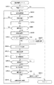
センサ930がセンサ931より先にONした場合は、ステップS3103に移行する。ステップS3103では、SKEW_CN(斜行検出用カウンタに相当)を0クリアする。次いで、skew_detectf_g(斜行検出中フラグに相当)をONし(ステップS3104)、その後、センサ931がONするのを待つ(ステップS3105)。
【0198】
一方、センサ931がセンサ930より先にONした場合は、ステップS3106に移行する。ステップS3106では、SKEW_CN(斜行検出用カウンタ)を0クリアする。次いで、skew_detectf_g(斜行検出中フラグ)をONし(ステップS3107)、その後、センサ930がONするのを待つ(ステップS3108)。
【0199】
ステップS3105でセンサ931がONしたことを判定した場合、または、ステップS3108でセンサ930がONしたことを判定した場合、skew_detectf_g(斜行検出中フラグ)をOFFする(ステップS3109)。次いで、skew_detectf_g(斜行検出中フラグ)のONからOFFまでの間にカウントしたSKEW_CN(斜行検出用カウンタ)のカウント値をチェックする(ステップS3110)。以上までの処理が、シートの斜行量を検出する為の処理である。このように本形態は、センサ930のシート検出時間とセンサ931のシート検出時間との間にカウントしたSKEW_CN(斜行検出用カウンタ)の値に基づいて、シート給送方向に対するシートの斜行量を算出している。
【0200】
そして、ステップS3110にてチェックしたSKEW_CN(斜行検出用カウンタ)の値が、SKEW_REF1(斜行基準値1に相当)以下の場合(SKEW_CN≦SKEW_REF1の場合)は、該処理を終了し、図24のステップ2403に移行する。
【0201】
また、ステップS3110にてチェックしたSKEW_CN(斜行検出用カウンタ)の値が、SKEW_REF2(斜行基準値2に相当)を越える場合(SKEW_REF2<SKEW_CNの場合)は、インサータ斜行ジャムをセットし、全負荷(例えば、モータM1〜M4、及びモータM10〜M12、及び給送モータM20、及びパンチモータM30、及び、クラッチCL1、CL10及び、ソレノイドSL1、SL2、SL10、SL20、SL21等)の停止を行うと共に、複写機本体側のCPU回路部150に緊急停止処理を促す(ステップS3111)。尚、フィニッシャ制御部501から情報を受け取った本体側のCPU回路部150は、その旨を操作部1の操作パネルに表示させ、ユーザに対する通知を行うと共に、フィニッシャ500内部にシートを送り込まないよう画像形成されたシートの搬送動作を停止させる。
【0202】
全負荷を停止させることで、インサータ900からのシートの給送動作や、フィニッシャ500内におけるシート搬送動作を停止し、また、パンチユニット550によるシートに対するパンチ処理や、ステイプラ601によるステイプル処理等を行うこともすべて禁止する。そして、ユーザによりシートが取り除かれるまでの間、上述したようなフィニッシャ500内における動作をすべて禁止する。尚、ユーザによるシートの除去作業が行われたことに応じてフィニッシャ500内における動作の禁止を解除し、その旨を本体側のCPU回路部150に通知する。フィニッシャ制御部501から情報を受け取った本体側のCPU回路部150は、その旨を操作部1の操作パネルに表示させ、ユーザに対する通知を行う。
【0203】
また、ステップS3110にてチェックしたSKEW_CN(斜行検出用カウンタ)の値が、SKEW_REF1(斜行基準値1に相当)を越え、且つ、SKEW_REF2(斜行基準値2に相当)以下の場合は(SKEW_REF1<SKEW_CN≦SKEW_REF2の場合)は、図7(a)に示した操作部1の後処理選択メニュー画面において、ユーザによりパンチモードが設定されているか否かを判定し(ステップS3112)、パンチモードが設定されていないと判定した場合は、このまま該処理を終了し、図24のステップ2403に移行する。
【0204】
一方、ステップS3112において、パンチモードが設定されていると判定した場合は、ステップS3111と同様、インサータ斜行ジャムをセットし、全負荷(例えば、モータM1〜M4、及びモータM10〜M12、及び給送モータM20、及びパンチモータM30、及び、クラッチCL1、CL10及び、ソレノイドSL1、SL2、SL10、SL20、SL21等)の停止を行うと共に、複写機本体側のCPU回路部150に緊急停止処理を促す(ステップS3113)。尚、フィニッシャ制御部501から情報を受け取った本体側のCPU回路部150は、その旨を操作部1の操作パネルに表示させ、ユーザに対する通知を行うと共に、フィニッシャ500内部にシートを送り込まないよう画像形成されたシートの搬送動作を停止させる。
【0205】
全負荷を停止させることで、インサータ900からのシートの給送動作や、フィニッシャ500内におけるシート搬送動作を停止し、また、パンチユニット550によるシートに対するパンチ処理や、ステイプラ601によるステイプル処理等を行うこともすべて禁止する。そして、ユーザによりシートが取り除かれるまでの間、上述したようなフィニッシャ500内における動作をすべて禁止する。尚、ユーザによるシートの除去作業が行われたことに応じてフィニッシャ500内における動作の禁止を解除し、その旨を本体側のCPU回路部150に通知する。フィニッシャ制御部501から情報を受け取った本体側のCPU回路部150は、その旨を操作部1の操作パネルに表示させ、ユーザに対する通知を行う。
【0206】
ステップS3112の処理に関し、例えば、SKEW_REF1<SKEW_CN≦SKEW_REF2の場合において、ユーザにより設定された動作モードがパンチモード以外のモード、例えば、ステイプルソートモード、ソートモード、製本モード等(図7(a)参照)の何れかであった場合には、全負荷を停止すること無く、そのままシートの搬送動作を継続する。
【0207】
これは、図5を参照して、例えば、ステイプル処理を行う場合、該処理に先行して処理トレイ630上でシートの整合処理が行われ、また、製本処理を行う場合も、該処理に先行して収納ガイド820内でシートの整合処理が行われるからであり、検出したシートの斜行量がSKEW_REF2(斜行基準値2に相当)以下であれば、最終的な処理を施す前にシートの斜行を補正することが可能だからである。即ち、ステイプルソート処理やソート処理や製本処理等のパンチ処理以外の処理を行う場合は、最終的な束処理におけるシートの整合性の品位が損なわれる心配が無い。
【0208】
一方、パンチ処理は、生産性及びコストを考量して、シート搬送経路上において、シートの搬送動作と共に行うものであり、上述したようなシートの整合処理を行っていない。このような理由により、本形態では、パンチ処理の場合、他の処理よりも斜行ジャム検出を厳密に行っている。尚、SKEW_REF2(斜行基準値2に相当)は、シートを搬送している最中に紙詰まりが生じる虞があることを考慮した値であり、この値を越える場合は全負荷を停止する。
【0209】
また、緊急停止処理を行った場合、実際にシートの紙詰まりが生じる前にシートの搬送動作を停止させることが可能なので、シートの品位が損なわれる可能性が少ない。従って、ユーザがフィニッシャ500内部からシートを取り除き、再び該シートをインサータのトレイ901にセットし直し、操作部1から処理再開の指示を出すことにより、該シートを再利用出来る。これにより、紙詰まりが発生したことによりシートが破れたり、汚れたりして、ユーザが再度同一のシートを用意しなければならない等の不具合が生じることを防止することが出来る。
【0210】
このように、本形態では、インサータ900からのシートの斜行量をセンサ930及びセンサ931により検出し、検出したシートの斜行量及びパンチ処理を行うか否かの判定結果に応じて制御を切り替えている。例えば、斜行基準値1を3mmとし、斜行基準値2を9mmとした場合に、センサ930及びセンサ931により検出したインサータ900からのシートの斜行量が、9mmを越えている場合は、シートの紙詰まりが生じる可能性があるので、緊急停止を行い、シートの給送処理及び搬送処理、パンチ処理等の処理を行うことを禁止する。また、検出したシートの斜行量が3mm以下の場合は、緊急停止を行わず、シートの給送処理及び搬送処理、パンチ処理等の処理を行うことを許可する。
【0211】
また更に、例えば、検出したシートの斜行量が3mmを越え9mm以下の場合において、パンチモードが予めユーザにより設定されている場合は、所望する位置に穴あけ処理を行うことが出来ない可能性があるので、緊急停止を行い、シートの給送動作及び搬送動作、パンチ処理等の処理を行うことを禁止する。これにより、所望する位置に穴あけ処理が行なわれなかった為にユーザが再度同一のシートを作成するといった余計な手間や労力を省くことが出来る。一方、検出したシートの斜行量が3mmを越え9mm以下の場合において、パンチ処理が予めユーザにより設定されていない場合は、シートの整合性の品位が損なわれる心配がないので、緊急停止は行わず、そのままシートの搬送動作を継続するよう制御し、生産性の向上をはかる。
【0212】
尚、図30及び図31を用いて説明した処理(機能)を実現する為のプログラムは、フィニッシャ制御部501のROM512にプログラムコードとして記憶し、フィニッシャ制御部のCPU511が該コードを読み出してその機能を実行しても良いし、複写機本体側のCPU回路部150のROM151に記憶し、CPU回路部150のCPU(不図示)が読み出して実行しても良い。
【0213】
以上説明したように、本形態により、インサータ900からシートが斜行した状態で搬送されたとしても、インサータ900からのシートを搬送している際に装置内部で紙詰まりが発生し、それによりシートが破損したり、汚れたりして、シートの品位が損なわれたりするといった不具合が生じることを防止出来ると共に、シート上の所望する位置に所定の加工処理(綴じ処理、パンチ処理、折り処理等)が施されていない等の不具合が生じることを防止出来る。従って、ユーザが再度同一のシートを用意しなければならないといった不具合が解消されるので、ユーザに対する余計な手間や労力を削減し、コスト高となることを防止することが出来る。
【0214】
また、インサータ900から供給されるシートは、付加価値の高い特殊なシート(例えば、写真のような画像が形成されているシートやカタログの表紙、光沢紙、色付きのシート等)や、現在使用している複写機(例えば、白黒複写機)では作成不可能なシート(例えば、カラー出力用紙)である可能性が高いので、上述したような効果が一層高まる。
【0215】
また、本形態におけるパンチ処理のように、シート整合処理を行わないでシートに対して加工処理を施すものであれば、本形態の構成は特に有効である。
【0216】
【発明の効果】
以上説明したように、本発明によれば、第1の積載手段から搬送されるシートの斜行量を検出し、シート加工処理を行うか否かを判定し、検出したシートの斜行量および判定結果に基づいて、搬送手段によるシートの搬送を制御するので、第1の積載手段からシートが斜行した状態で搬送されたとしても、ユーザに対する余計な手間や労力が増大することなく、コスト高となることを防止することが出来る。
【図面の簡単な説明】
【図1】複写装置の一例を示す断面図である。
【図2】原稿固定読みの場合と原稿流し読みの場合の夫々の場合における画像形成処理方法に関する説明を行う為の図である。
【図3】複写装置のブロック図である。
【図4】画像信号制御部の詳細な説明を行う為のブロック図である。
【図5】折り処理部及びフィニッシャの構成を示す図である。
【図6】フィニッシャ制御部の構成を示すブロック図である。
【図7】操作部の表示パネルを示す図である。
【図8】処理トレイ上にインサータからのシートとプリンタ部からのシートが収納される際のシートの流れを説明する為の図である。
【図9】処理トレイ上にインサータからのシートとプリンタ部からのシートが収納される際のシートの流れを説明する為の図である。
【図10】処理トレイ上にインサータからのシートとプリンタ部からのシートが収納される際のシートの流れを説明する為の図である。
【図11】処理トレイ上にインサータからのシートとプリンタ部からのシートが収納される際のシートの流れを説明する為の図である。
【図12】処理トレイ上にインサータからのシートとプリンタ部からのシートが収納される際のシートの流れを説明する為の図である。
【図13】処理トレイ上にインサータからのシートとプリンタ部からのシートが収納される際のシートの流れを説明する為の図である。
【図14】製本処理について説明する為の図である。
【図15】製本モード時のインサータ及びプリンタ部からフィニッシャ内の収納ガイドへのシートの流れを説明する為の図である。
【図16】製本モード時のインサータ及びプリンタ部からフィニッシャ内の収納ガイドへのシートの流れを説明する為の図である。
【図17】製本モード時のインサータ及びプリンタ部からフィニッシャ内の収納ガイドへのシートの流れを説明する為の図である。
【図18】製本モード時のインサータ及びプリンタ部からフィニッシャ内の収納ガイドへのシートの流れを説明する為の図である。
【図19】製本モード時のインサータ及びプリンタ部からフィニッシャ内の収納ガイドへのシートの流れを説明する為の図である。
【図20】製本モード時のインサータ及びプリンタ部からフィニッシャ内の収納ガイドへのシートの流れを説明する為の図である。
【図21】製本モード時のインサータ及びプリンタ部からフィニッシャ内の収納ガイドへのシートの流れを説明する為の図である。
【図22】製本モード時のインサータ及びプリンタ部からフィニッシャ内の収納ガイドへのシートの流れを説明する為の図である。
【図23】動作モード判別処理のフローチャートを示す図である。
【図24】インサータ前給紙処理のフローチャートを示す図である。
【図25】ノンソート処理のフローチャートを示す図である。
【図26】ソート処理のフローチャートを示す図である。
【図27】ステイプルソート処理のフローチャートを示す図である。
【図28】製本処理のフローチャートを示す図である。
【図29】インサータ給紙処理のフローチャートを示す図である。
【図30】パンチ処理のフローチャートを示す図である。
【図31】斜行検知処理のフローチャートを示す図である。
【図32】パンチ処理を説明する為の図である。
【符号の説明】
1000 複写装置
100 原稿給送部
200 イメージリーダ部
300 プリンタ部
400 折り処理部
500 フィニッシャ
900 インサータ
150 CPU回路部
151 ROM
152 RAM
501 フィニッシャ制御部
511 CPU
512 ROM
513 RAM
550 パンチユニット
930 斜行センサ
931 斜行センサ[0001]
BACKGROUND OF THE INVENTION
The present invention relates to a sheet processing apparatus, an image forming apparatus, and the like that stack sheets on which images are formed.
[0002]
[Prior art]
2. Description of the Related Art Conventionally, a copying apparatus having a mode such as a cover sheet mode or a slip sheet mode in which a sheet different from a normal recording sheet (hereinafter referred to as a special sheet) is inserted into the first page, the last page, or an intermediate page of a recording sheet. is there. When the user sets these modes on the operation unit of the copying apparatus, for example, different color sheets or color copy sheets can be inserted as a cover sheet, or can be inserted as a partition sheet every arbitrary number of sheets.
[0003]
As a special sheet supply method, a special cassette provided on the copying machine main body side is supplied, or a sheet feeding unit for supplying a special sheet is provided on the sheet processing apparatus side such as a finisher. A method for supplying a special sheet has been proposed. In addition, it has been proposed that stapling and punching can be performed on a special sheet conveyed from the paper feeding unit.
[0004]
[Problems to be solved by the invention]
However, due to insufficient measures against skew feeding of special sheets conveyed from the paper feed unit or special cassette, special sheets are skewed from the paper feed unit or special cassette. If it has been transported, paper jams may occur in the middle of transport, or there may be problems such as a hole punching process not being performed at a desired position on the sheet. There arises a problem that it is necessary to prepare the sheet, and there is a possibility that the extra labor and labor for the user increase and the cost increases.
[0005]
[Means for Solving the Problems]
In order to solve the above problem, the present invention provides: It can be connected to an image forming apparatus, A first stacking unit that stacks sheets; a transport unit that transports a sheet stacked on the first stacking unit and a sheet on which an image is formed by the image forming apparatus;
A second stacking unit configured to stack a sheet from the first stacking unit transported by the transporting unit and a sheet from the image forming apparatus; Have According to the operation mode of the image forming apparatus, from the first stacking unit conveyed by the conveying unit Sheet and sheet from the image forming apparatus for Sheet processing is possible In the sheet processing apparatus, a detection unit that detects a skew amount of a sheet conveyed from the first stacking unit, a determination unit that determines whether or not to perform the sheet processing, and a sheet that is detected by the detection unit Control means for controlling the conveyance of the sheet by the conveying means based on the skew amount and the determination result by the determining means, And when the control unit determines that the sheet skew detected by the detection unit exceeds the first skew amount and the determination unit performs the sheet processing, the sheet by the transport unit Is stopped, the skew amount of the sheet detected by the detecting means exceeds the first skew amount, and the determination means determines that the sheet processing is not performed, the sheet by the conveying means Continuing the transport operation A sheet processing apparatus characterized by the above is provided.
[0008]
DETAILED DESCRIPTION OF THE INVENTION
FIG. 1 is a cross-sectional view showing the internal structure of a copying
[0009]
Referring to FIG. 1, a document is set on
[0010]
It is also possible to perform document reading processing by temporarily stopping the document conveyed by the
[0011]
The document image data read by the
[0012]
The electrostatic latent image formed on the photosensitive drum 111 is developed by the developing
[0013]
The recording paper that has passed through the
[0014]
As described above, when the image forming process is performed sequentially from the first page by discharging the recording paper face-down as described above, for example, when performing the image forming process using the
[0015]
When image forming processing is performed on a hard sheet such as an OHP sheet conveyed from the manual
[0016]
When image forming processing is performed on both sides of the sheet, the sheet is guided straight from the
[0017]
Next, an image forming processing method in each of the case of fixed original reading and the case of original scanning will be described with reference to FIG.
[0018]
In the case of fixed document reading, the document image is scanned by scanning the
[0019]
When the electrostatic latent image thus formed is visualized as a toner image and the toner image is formed on the sheet, a normal image (non-mirror image) that is not a mirror image is formed on the sheet.
[0020]
On the other hand, in the case of original flow reading, as shown in FIG. 2B, the original image is read and scanned with the main scanning direction as Sy and the sub-scanning direction Sx, and the
[0021]
That is, the mirror image processing of the present embodiment is processing for rotating the read image by 180 degrees and outputting it, as shown in FIG. 2B, and rotating the input image by 180 degrees. In this embodiment, this is called mirror image processing.
[0022]
An image read by the
[0023]
Although the mirror image processing can be performed by switching the sub-scanning direction to the reverse direction, in this case, the mirror image processing cannot be performed unless the image reading processing for one page of the document is completed, Considering binding of the left end side of the sheet to the image by rear end binding, mirror image processing by switching the main scanning direction is preferable.
[0024]
With reference to FIG. 1, the sheet discharged from the
[0025]
An
[0026]
FIG. 3 is a block diagram of the
[0027]
The
[0028]
FIG. 4 is a block diagram for explaining the image
[0029]
Next, the configuration of the
[0030]
The
[0031]
When performing the folding process, the switching
[0032]
The configuration of the
[0033]
As shown in FIG. 5, the
[0034]
The sheet guided to the
[0035]
An
[0036]
Branch A branches from the
[0037]
A
[0038]
The
[0039]
A switching
[0040]
The switching
[0041]
The sheet guided to the
[0042]
On the other hand, the sheet guided to the
[0043]
Sheets from the
[0044]
A
[0045]
Further, when the sheet bundle bound by the
[0046]
Next, the
[0047]
A sheet bundle stacked on the
[0048]
A
[0049]
Next, the configuration of the
[0050]
The
[0051]
When the drive control of the
[0052]
A
[0053]
The various motors include an
[0054]
The entrance motor M1, the buffer motor M2, and the paper discharge motor M3 are stepping motors, and by rotating the pair of rollers driven by each motor at a constant speed by controlling the excitation pulse rate or rotating at a unique speed. I can do it. Further, the inlet motor M1 and the buffer motor M2 can be driven by the
[0055]
The conveyance motor M10 and the positioning motor M11 are stepping motors, and the folding motor M12 is a DC motor. The conveyance motor M10 is configured to be able to convey the sheet in synchronism with the inlet motor M1.
[0056]
The sheet feeding motor M20 is composed of a stepping motor, and is configured to be able to convey the sheet in synchronization with the inlet motor M1.
[0057]
Solenoids include a solenoid SL1 that switches the switching
[0058]
Next, an operation mode setting method will be described with reference to FIG. FIGS. 7A and 7B show screens displayed on the display panel of the operation unit 1 of the copying apparatus
[0059]
On the screen shown in FIG. 7A, the user can select an operation mode such as a non-sort mode, a sort mode, a staple sort mode (binding mode), a bookbinding mode, or a punch mode (drilling processing mode).
[0060]
In the screen shown in FIG. 7B, the cover page mode and the slip sheet mode can be set, and the cover sheet and the slip sheet are inserted from the
[0061]
Next, sheet conveyance from the
[0062]
In this embodiment, a sheet conveyed from the
[0063]
When the sheet of the sheet bundle C is inserted as a cover into the sheet on which an image is formed by the
[0064]
Next, referring to FIG. 9, when the sheet bundle C is set on the
[0065]
The uppermost sheet C1 of the sheet bundle C conveyed to the
[0066]
Further, in response to the leading edge of the sheet C1 conveyed from the
[0067]
In the post-processing selection menu screen of the operation unit 1 shown in FIG. 7A, if the punch mode is set in advance by the user, the
[0068]
Thus, in this embodiment, the
[0069]
Next, referring to FIG. 10, the switching
[0070]
In this embodiment, the
[0071]
As described above, in the case of document scanning, mirror image processing (that is, processing for rotating the input image by 180 degrees) is performed on the read image so that a normal image is formed on the sheet. Then, an image subjected to the mirror image processing is formed on the sheet. Further, when the sheet on which the image is formed is discharged from the
[0072]
The sheet C1 conveyed to the
[0073]
Next, referring to FIG. 12, the sheet C <b> 1 is stored in the
[0074]
In the case of outputting the second copy, at this time, the sheet C2 for the cover of the second copy is conveyed to the
[0075]
Next, referring to FIG. 13, the sheet P1 is stacked and stored on the sheet C1 already stored in the
[0076]
As a post-processing, when a binding process is performed on a sheet bundle composed of a plurality of sheets, it is performed by the
[0077]
As described above, in this embodiment, the input image is rotated by 180 degrees as a process for aligning the orientation of the sheet image set on the
[0078]
Thus, when the sheet from the
[0079]
Further, regarding the conveyance of the sheet to the
[0080]
Also, the setting direction of the document set on the
[0081]
In this embodiment, referring to FIG. 1, the feeding direction (from right to left) of the documents stacked on the
[0082]
In this embodiment, the case where an image of a document is input from the
[0083]
8 to 13, the case where the sheet from the
[0084]
Next, the bookbinding process will be described with reference to FIG. This process is performed when the operation mode set by the user is the bookbinding mode on the display panel of the operation unit 1 shown in FIG. FIG. 14 is a diagram for explaining image forming processing in the bookbinding mode in the
[0085]
When the bookbinding mode is designated, the original set on the
[0086]
M = n × 4-k (1)
(M represents the number of documents. N is an integer equal to or greater than 1, and represents the number of sheets used when forming an image of the read document. K is a value of 0, 1, 2, or 3. To do).
[0087]
The image forming process in the bookbinding mode will be described by taking the case where the number of read originals is eight as an example. As shown in FIG. 14A, the
[0088]
Then, the image forming order and the image forming position are determined for each image data (R1 to R8). As a result, as shown in FIG. 14B, an R4 image is formed on the left half of the first surface (front surface) of the sheet P1 of the first page, and an R5 image is formed on the right half. Is done. Note that the image formed on the sheet is an image after the mirror image processing is performed as described above.
[0089]
The sheet P1 on which the images R4 and R5 are formed is fed again to the
[0090]
When the sheet P1 is conveyed from the
[0091]
Subsequent to the processing described above, the R2 image is formed on the left half and the R7 image is formed on the right half of the first surface (front surface) of the sheet P2 of the second page (see FIG. 14B). ). Note that the image formed on the sheet is an image after the mirror image processing is performed as described above.
[0092]
The sheet P2 on which the images R2 and R7 are formed is fed again to the
[0093]
When the sheet P2 is conveyed from the
[0094]
The sheet P1 and the sheet P2 are sequentially guided and stored in the
[0095]
Next, sheet conveyance from the
[0096]
When the sheet C1 is inserted into a sheet after image formation as a cover and bound, the sheet C1 is set on the
[0097]
That is, the sheet C1 is set in an upright state and a face-up state as viewed from the user, and the sheet setting state (sheet stacking direction with respect to the tray 901) is a document setting state (tray in the document feeding unit 100). This is the same as the original stacking direction with respect to 1001. Therefore, the operability when setting a sheet on the
[0098]
When the user sets a sheet bundle including the sheet C1 on the
[0099]
Next, referring to FIG. 17, the switching
[0100]
When the sheet C1 is guided to the
[0101]
On the other hand, the sheet P1 from the
[0102]
In the present embodiment, an example is given of the case where bookbinding is performed with a total of three sheets, the sheet C1 from the
[0103]
When the sheet P1 and the sheet P2 are stored in the
[0104]
At this time, since the sheet C1 is reversely fed, as shown in FIG. 20, the sheet C1 is conveyed with the image R side as the head, and is composed of the sheet P1 and the sheet P2 that are already stored in the
[0105]
When outputting the second copy, the conveyance of the sheet C2 is resumed so that the sheet C2 following the sheet C1 is conveyed toward the
[0106]
After the sheet C1 is stored in the
[0107]
In the folded sheet bundle, as shown in FIG. 22B, the image F of the sheet C1 is arranged on the cover page, and the image R of the sheet C1 is arranged on the last page. In addition, the images of the sheets P1 and P2 are arranged in the page order, and the orientations of the images of the sheets C1 and P1 and P2 match.
[0108]
As described above, when the bookbinding process is performed on a sheet bundle composed of a plurality of sheets, the sheet from the inserter 900 (in this case) is controlled by the sheet feeding control from the
[0109]
In the state where the sheet C1 is stored in the
[0110]
Next, processing related to the drive control of the
[0111]
FIG. 23 is a flowchart regarding the operation mode determination processing for the
[0112]
First, it is checked whether or not a finisher start signal for instructing the
[0113]
If it is determined in step S2301 that a finisher start signal has been input to the
[0114]
If it is determined in step S2303 that there is a paper feed request for the
[0115]
If it is determined in step S2303 that there is no paper feed request for the
[0116]
Next, based on the post-processing mode data received from the
[0117]
If it is determined in step S2306 that the set operation mode is the bookbinding mode, bookbinding processing is performed (step S2307). A detailed description of the bookbinding process in step S2307 will be described later with reference to FIG. When the bookbinding process in step S2307 is completed, the process returns to step S1.
[0118]
If it is determined in step S2306 that the set operation mode is not the bookbinding mode, it is determined whether or not the punch mode is set by the user on the post-processing selection menu screen shown in FIG. In step S2313), if the punch mode is set, the punch mode flag is turned on (step S2314), and the process proceeds to step S2308. On the other hand, if it is determined that the punch mode is not set, the process proceeds to step S2308. Transition. In step S2308, it is determined whether the set operation mode is a non-sort mode, a sort mode, or a staple sort mode.
[0119]
If it is determined in step S2308 that the set operation mode is the non-sort mode, non-sort processing is performed (step S2309). A detailed description of the non-sort process in step S2309 will be described later with reference to FIG.
[0120]
If it is determined in step S2308 that the set operation mode is the sort mode, a sort process is performed (step S2310). A detailed description of the sorting process in step S2310 will be described later with reference to FIG.
[0121]
If it is determined in step S2308 that the set operation mode is the staple sort mode, staple sort processing is performed (step S2311). A detailed description of the staple sort process in step S2311 will be described later with reference to FIG.
[0122]
When the non-sort process is completed in step S2309, the sort process is completed in step S2310, or the staple sort process is completed in step S2311, the driving of the inlet motor M1 is stopped, and the process proceeds to step S2314. If the punch mode flag is turned ON, the punch mode flag is turned OFF (step S2312). Then, the process returns to step S1 and waits for the input of the finisher start signal.
[0123]
Even when any of the processes of step S2307, step S2309, step S2310, and step S2311 is performed, if it is determined in step S2303 that there is a paper feed request to the
[0124]
Next, with reference to FIG. 24, a detailed description will be given regarding the pre-inserter paper feed process in step S2304 described above. FIG. 24 is a flowchart for explaining the details of the pre-inserter paper feed process in step S2304 of FIG. This process is performed when it is determined in step S2303 in FIG. 23 that there is a paper feed request to the
[0125]
In the pre-inserter paper feed process, first, a pre-paper feed check is performed (step S2400). In step S2400, whether or not there is a sheet on the
[0126]
In step S2400, a pre-feed check is performed, and if it is confirmed that a paper feed condition for feeding sheets from the
[0127]
When the process of step S2401 is completed, the driving of the paper feed motor M20 is started after a predetermined time, and the
[0128]
If the process of step S2402 is performed, skew detection processing is performed (step S2413). Detailed description of the skew detection processing will be described later with reference to FIG.
[0129]
Next, a first transport process is performed (step S2403). In the processing of step S2403, the conveyance status of the sheet C1 is monitored by the
[0130]
The processing in step S2403 is a step for temporarily stopping the sheet from the
[0131]
It is checked whether there is a request for refeeding the sheet C1 to the
[0132]
In step S2404, if there is a request for refeeding the sheet C1, the second conveyance process is performed (step S2405). In step S2405, the sheet feeding motor M20 is restarted to guide the sheet C1 stopped before the conveying
[0133]
Next, based on the transport direction length of the sheet C1 calculated in step S2405 and the specified size data acquired in step S2400 described above, it is checked whether or not the sheet C1 from the
[0134]
If it is determined in step S2406 that the sheet C1 from the
[0135]
In step S2412 described above, the image formation signal inhibition signal sent to the
[0136]
On the other hand, when it is determined in step S2406 that the sheet C1 from the
[0137]
If the determined operation mode is the non-sort mode in step S2408, the non-sort paper feed process is executed (step S2409). In step S2409, the sheet C1 from the
[0138]
If the determined operation mode is the sort mode or the staple mode in step S2408, the pre-stack paper feed process is executed (step S2410), and the process proceeds to step S2412.
[0139]
In
[0140]
If the determined operation mode is the bookbinding mode in step S2408, the pre-bookbinding paper feed process is executed (step S2411). In the process of step S2411, the switching
[0141]
The inserter pre-feed process shown in FIG. 24 is a process for conveying a sheet from the
[0142]
Next, the non-sort process in step S2309 in FIG. 23 will be described using the flowchart in FIG. This process is performed when it is determined in step S2308 in FIG. 23 that the operation mode is the non-sort mode.
[0143]
In the non-sorting process, first, the switching
[0144]
Next, it is determined whether or not the finisher start signal for the
[0145]
Step S2503 is a step for detecting whether or not a sheet is conveyed from the
[0146]
If it is determined in step S2503 that the
[0147]
If it is determined in step S2502 that the finisher start signal has been turned off, it is checked whether all sheets from the
[0148]
If it is determined in step S2505 that all sheets from the
[0149]
Next, the sorting process in step S2310 in FIG. 23 will be described using the flowchart in FIG. This processing is performed when it is determined in step S2308 in FIG. 23 that the operation mode is the sort mode.
[0150]
In the sort process, first, the switching
[0151]
Next, it is determined whether or not the finisher start signal for the
[0152]
Step S2603 is a step for detecting whether or not a sheet is conveyed from the
[0153]
If it is determined in step S2603 that the
[0154]
As the sort sheet sequence in step S2604, multitask processing is performed by the
[0155]
If the process of step S2604 is performed, it will wait until the
[0156]
If it is determined in step S2602 that the finisher start signal has been turned off, it is checked in step S2604 whether all the sheet bundles that should be subjected to the bundle discharge process have been discharged onto the stack tray 700 (step S2606).
[0157]
If it is determined in step S2606 that all the sheet bundles to be subjected to bundle discharge processing have not been discharged onto the
[0158]
Next, the staple sort process in step S2311 in FIG. 23 will be described with reference to the flowchart in FIG. This process is performed when it is determined in step S2308 in FIG. 23 that the operation mode is the staple sort mode.
[0159]
In the staple sorting process, first, the switching
[0160]
Next, it is determined whether or not the finisher start signal for the
[0161]
Step S 2703 is a step for detecting whether or not a sheet is conveyed from the
[0162]
If it is determined in step S2703 that the
[0163]
As the staple sort paper sequence in step S2704, multitask processing is performed by the
[0164]
If the process of step S2704 is performed, it will wait until the
[0165]
If it is determined in step S2702 that the finisher start signal has been turned off, it is checked in step S2704 whether or not all the sheet bundles to be subjected to bundle ejection processing have been ejected onto the stack tray 700 (step S2706).
[0166]
If it is determined in step S2706 that all the sheet bundles to be subjected to bundle discharge processing have not been discharged onto the
[0167]
Next, the bookbinding process in step S2307 in FIG. 23 will be described using the flowchart in FIG. This processing is performed when it is determined in step S2306 in FIG. 23 that the operation mode is the bookbinding mode.
[0168]
In the bookbinding process, first, it is determined based on the size information whether the size of the sheet conveyed from the
[0169]
On the other hand, if it is determined in step S2801 that the sheet size is suitable for bookbinding, a bookbinding initial operation is performed (step S2802). In the bookbinding initial operation in step S2802, the conveyance motor M10 is driven to rotate the
[0170]
Next, it is determined whether or not the sheet from the
[0171]
On the other hand, if it is determined in step S2803 that the sheet from the
[0172]
Next, it is determined whether or not the sheet processed in step S2804 is the final sheet of the sheet to be bound as one bundle (step S2805). If the sheet is not the final sheet, the process proceeds to step S2802. Return. On the other hand, if it is determined in step S2805 that the sheet is the final sheet, an image formation prohibition signal is output to the
[0173]
Next, on the screen of the operation unit 1 shown in FIG. 7B, it is determined whether or not the user designates paper feed from the inserter 900 (step S2807), and paper feed from the
[0174]
On the other hand, if it is determined in step S2807 that the sheet feeding from the
[0175]
When the process of step S2809 is executed, a bundle transport process is executed (step S2810). In the bundle conveying process in step S2810, the positioning motor M1 is driven to lower the
[0176]
When the process of step S2810 is executed, a folding control process is executed (step S2811). In the folding control process in step S2811, the clutch CL1 is driven and the folding motor M12 is driven to move the protruding
[0177]
By the folding control process, the center of the sheet bundle (that is, the staple position on the sheet) is guided to the nip point of the
[0178]
When the process of step S2811 is executed, it is checked based on the detection signal from the bookbinding
[0179]
On the other hand, if it is determined in step S2812 that the sheet bundle has been discharged to the
[0180]
If it is determined in step S2814 that it is the last sheet bundle to be bound, the bookbinding mode is terminated (step S2815). In the bookbinding mode end process in step S2815, the above-described width adjusting member and
[0181]
On the other hand, if it is determined in step S2814 that the sheet bundle is not the last sheet bundle to be bound, the image formation prohibition signal is canceled, and the
[0182]
Next, the inserter paper feed process in step S2808 of FIG. 28 will be described using the flowchart of FIG. This process is performed when it is determined in step S2807 in FIG. 28 that the sheet feeding from the
[0183]
In this embodiment, prior to the inserter paper feed process, the pre-inserter paper feed process shown in FIG. 24 is executed. The sheet C1 from the
[0184]
In the inserter paper feed process, first, reverse conveyance of a sheet from the
[0185]
Next, it is determined whether or not the
[0186]
In step S2901, when the rear end of the sheet C1 from the
[0187]
Next, it is confirmed whether or not the currently processed sheet bundle is the last sheet bundle to be bound (step S2903). If it is determined that the sheet bundle is not the last sheet bundle, the above-described pre-inserter sheet feeding process is performed. An activation command for activating is issued (step S2904). When the activation command is issued, the pre-inserter paper feed process is performed in parallel with the bookbinding process described above.
[0188]
Next, based on the detection signal from the
[0189]
If it is determined in step S2905 that the sheet C1 from the
[0190]
Next, the punch mode process will be described with reference to the flowchart shown in FIG. The processing is executed by the
[0191]
First, an instruction to start the operation to the
[0192]
If it is determined in step S3001 that the finisher start signal is ON, it is determined whether or not the punch mode flag is ON in step S2314 shown in FIG. 23 (step S3002). If is not ON, the process returns to step S3001. On the other hand, if the punch mode flag is ON, it is determined whether the
[0193]
If it is determined in step S3003 that the
[0194]
On the other hand, if it is determined in step S3003 that the
[0195]
Next, with reference to the flowchart shown in FIG. 31, the skew detection process in step S2413 of FIG. 24 described above will be described in detail. This process is performed subsequent to the process of step S2402 in FIG. 24, and is executed by the
[0196]
First, it is determined whether or not the skew sensor 930 is turned on (step S3101). If it is determined that the sensor 930 is not turned on, it is determined whether or not the sensor 931 is turned on (step S3102), and the sensor 931 is turned on. If it is determined that it is not, the process returns to step S3101 again. The processes in steps S3101 and S3102 are repeated until either the sensor 930 or the sensor 931 is turned on (until the leading edge of the sheet reaches the sensor 930 or 931). As described above, the sensor 930 and the sensor 931 are disposed at different positions on the same line in the direction orthogonal to the sheet conveying direction. Therefore, if the sheet is fed obliquely from the
[0197]
When the sensor 930 is turned on before the sensor 931, the process proceeds to step S3103. In step S3103, SKEW_CN (corresponding to the skew detection counter) is cleared to zero. Next, skew_detectf_g (corresponding to the skew detection flag) is turned on (step S3104), and thereafter, it waits for the sensor 931 to be turned on (step S3105).
[0198]
On the other hand, when the sensor 931 is turned on before the sensor 930, the process proceeds to step S3106. In step S3106, SKEW_CN (skew detection counter) is cleared to zero. Next, skew_detectf_g (diagnosis detection flag) is turned on (step S3107), and thereafter, it waits for the sensor 930 to be turned on (step S3108).
[0199]
If it is determined in step S3105 that the sensor 931 has been turned on, or if it is determined in step S3108 that the sensor 930 has been turned on, skew_detectf_g (skew detection flag) is turned off (step S3109). Next, the count value of SKEW_CN (skew detection counter) counted from the time when skew_detectf_g (skew detection flag) is ON to OFF is checked (step S3110). The above processing is processing for detecting the skew amount of the sheet. As described above, in the present embodiment, the skew amount of the sheet with respect to the sheet feeding direction based on the value of SKEW_CN (counter for skew detection) counted between the sheet detection time of the sensor 930 and the sheet detection time of the sensor 931. Is calculated.
[0200]
If the value of SKEW_CN (skew detection counter) checked in step S3110 is equal to or less than SKEW_REF1 (corresponding to skew reference value 1) (when SKEW_CN ≦ SKEW_REF1), the processing is terminated, and FIG. The process proceeds to step 2403.
[0201]
Also, if the value of SKEW_CN (skew detection counter) checked in step S3110 exceeds SKEW_REF2 (corresponding to skew reference value 2) (when SKEW_REF2 <SKEW_CN), inserter skew jam is set, Stop all loads (for example, motors M1 to M4, motors M10 to M12, feed motor M20, punch motor M30, clutches CL1, CL10, solenoids SL1, SL2, SL10, SL20, SL21, etc.) At the same time, the
[0202]
By stopping the entire load, the sheet feeding operation from the
[0203]
If the value of SKEW_CN (skew detection counter) checked in step S3110 exceeds SKEW_REF1 (equivalent to skew reference value 1) and is less than or equal to SKEW_REF2 (equivalent to skew reference value 2) ( In the case of SKEW_REF1 <SKEW_CN ≦ SKEW_REF2), it is determined whether or not the punch mode is set by the user on the post-processing selection menu screen of the operation unit 1 shown in FIG. 7A (step S3112). If it is determined that is not set, the process is terminated as it is, and the process proceeds to step 2403 in FIG.
[0204]
On the other hand, if it is determined in step S3112 that the punch mode is set, the inserter skew jam is set and the full load (for example, motors M1 to M4 and motors M10 to M12, and the supply) is set as in step S3111. Feed motor M20, punch motor M30, clutches CL1, CL10, solenoids SL1, SL2, SL10, SL20, SL21, etc.) and urgently stop the
[0205]
By stopping the entire load, the sheet feeding operation from the
[0206]
Regarding the processing in step S3112, for example, when SKEW_REF 1 <
[0207]
Referring to FIG. 5, for example, when stapling is performed, sheet alignment processing is performed on the
[0208]
On the other hand, the punching process is performed together with the sheet conveying operation on the sheet conveying path in consideration of productivity and cost, and the sheet alignment process as described above is not performed. For this reason, in this embodiment, skew jam detection is performed more strictly than in other processes in the punch process. Note that SKEW_REF2 (corresponding to the skew reference value 2) is a value considering that there is a possibility that a paper jam may occur during the conveyance of the sheet. When this value is exceeded, the full load is stopped.
[0209]
Further, when the emergency stop process is performed, the sheet conveying operation can be stopped before the sheet is actually jammed, so that there is little possibility that the quality of the sheet is impaired. Accordingly, the user can reuse the sheet by removing the sheet from the
[0210]
As described above, in this embodiment, the skew amount of the sheet from the
[0211]
Still further, for example, when the detected skew amount of the sheet is more than 3 mm and not more than 9 mm, if the punch mode is set in advance by the user, there is a possibility that the punching process cannot be performed at a desired position. Therefore, an emergency stop is performed, and it is prohibited to perform processing such as sheet feeding operation and conveyance operation, and punch processing. As a result, since the punching process is not performed at a desired position, it is possible to save an extra effort and labor for the user to create the same sheet again. On the other hand, when the detected skew amount of the sheet is greater than 3 mm and equal to or less than 9 mm, if the punching process is not set in advance by the user, there is no concern that the integrity of the sheet will be deteriorated, so an emergency stop is performed. First, control is performed so as to continue the sheet conveying operation, and productivity is improved.
[0212]
A program for realizing the processing (function) described with reference to FIGS. 30 and 31 is stored as a program code in the
[0213]
As described above, according to the present embodiment, even when the sheet is conveyed from the
[0214]
The sheet supplied from the
[0215]
In addition, the configuration of the present embodiment is particularly effective as long as the sheet is processed without performing the sheet alignment process as in the punching process of the present embodiment.
[0216]
【The invention's effect】
As described above, according to the present invention, the skew amount of the sheet conveyed from the first stacking unit is detected and the sheet processing is performed. Or Since the conveyance of the sheet by the conveyance unit is controlled based on the detected skew amount of the sheet and the determination result, even if the sheet is conveyed in a skewed state from the first stacking unit, It is possible to prevent an increase in cost without increasing unnecessary labor and labor for the user.
[Brief description of the drawings]
FIG. 1 is a cross-sectional view illustrating an example of a copying apparatus.
FIG. 2 is a diagram for explaining an image forming processing method in each of a case of fixed original reading and a case of original scanning;
FIG. 3 is a block diagram of a copying apparatus.
FIG. 4 is a block diagram for explaining in detail an image signal control unit;
FIG. 5 is a diagram illustrating a configuration of a folding processing unit and a finisher.
FIG. 6 is a block diagram illustrating a configuration of a finisher control unit.
FIG. 7 is a diagram showing a display panel of an operation unit.
FIG. 8 is a diagram for explaining the flow of a sheet when a sheet from an inserter and a sheet from a printer unit are stored on a processing tray.
FIG. 9 is a diagram for explaining a sheet flow when a sheet from an inserter and a sheet from a printer unit are stored on a processing tray.
FIG. 10 is a diagram for explaining the flow of sheets when sheets from an inserter and sheets from a printer unit are stored on a processing tray.
FIG. 11 is a diagram for explaining the flow of sheets when sheets from the inserter and sheets from the printer unit are stored on the processing tray.
FIG. 12 is a diagram for explaining a sheet flow when a sheet from an inserter and a sheet from a printer unit are stored on a processing tray.
FIG. 13 is a diagram for explaining the flow of sheets when sheets from the inserter and sheets from the printer unit are stored on the processing tray.
FIG. 14 is a diagram for explaining bookbinding processing.
FIG. 15 is a diagram for explaining the flow of a sheet from the inserter and the printer unit to the storage guide in the finisher in the bookbinding mode.
FIG. 16 is a diagram for explaining the flow of a sheet from the inserter and the printer unit to the storage guide in the finisher in the bookbinding mode.
FIG. 17 is a diagram for explaining the flow of sheets from the inserter and the printer unit to the storage guide in the finisher in the bookbinding mode.
FIG. 18 is a diagram for explaining the flow of a sheet from the inserter and the printer unit to the storage guide in the finisher in the bookbinding mode.
FIG. 19 is a diagram for explaining the flow of a sheet from the inserter and the printer unit to the storage guide in the finisher in the bookbinding mode.
FIG. 20 is a diagram for explaining the flow of sheets from the inserter and the printer unit to the storage guide in the finisher in the bookbinding mode.
FIG. 21 is a diagram for explaining the flow of a sheet from the inserter and the printer unit to the storage guide in the finisher in the bookbinding mode.
FIG. 22 is a diagram for explaining the flow of a sheet from the inserter and the printer unit to the storage guide in the finisher in the bookbinding mode.
FIG. 23 is a diagram illustrating a flowchart of an operation mode determination process.
FIG. 24 is a diagram illustrating a flowchart of a pre-inserter paper feed process.
FIG. 25 is a diagram illustrating a flowchart of non-sort processing.
FIG. 26 is a diagram illustrating a flowchart of sort processing.
FIG. 27 is a diagram illustrating a flowchart of staple sorting processing;
FIG. 28 is a diagram illustrating a flowchart of bookbinding processing.
FIG. 29 is a diagram illustrating a flowchart of inserter paper feed processing.
FIG. 30 is a diagram showing a flowchart of punch processing.
FIG. 31 is a diagram illustrating a flowchart of skew detection processing;
FIG. 32 is a diagram for explaining punch processing.
[Explanation of symbols]
1000 Copying machine
100 Document feeder
200 Image reader
300 Printer section
400 Folding section
500 Finisher
900 Inserter
150 CPU circuit
151 ROM
152 RAM
501 Finisher control unit
511 CPU
512 ROM
513 RAM
550 punch unit
930 Skew sensor
931 Skew sensor
Claims (6)
シートを積載する第1の積載手段と、
前記第1の積載手段に積載されたシート及び前記画像形成装置により画像形成されたシートを搬送する搬送手段と、
前記搬送手段により搬送された前記第1の積載手段からのシート及び前記画像形成装置からのシートを積載する第2の積載手段とを有し、
前記画像形成装置の動作モードに応じて前記搬送手段により搬送される前記第1の積載手段からのシート及び前記画像形成装置からのシートに対してシート加工処理が可能なシート処理装置において、
前記第1の積載手段から搬送されるシートの斜行量を検出する検出手段と、
前記シート加工処理を行うか否かを判定する判定手段と、
前記検出手段により検出したシートの斜行量および前記判定手段による判定結果に基づいて、前記搬送手段によるシートの搬送を制御する制御手段と、を有し、
前記制御手段は、前記検出手段により検出したシートの斜行量が第1の斜行量を越え、前記判定手段により前記シート加工処理を行うと判定した場合は、前記搬送手段によるシートの搬送動作を停止し、前記検出手段により検出したシートの斜行量が第1の斜行量を越え、前記判定手段により前記シート加工処理を行わないと判定した場合は、前記搬送手段によるシートの搬送動作を継続することを特徴とするシート処理装置。 It can be connected to an image forming apparatus,
A first stacking means for stacking sheets;
A conveying unit configured to convey a sheet stacked on the first stacking unit and a sheet formed with an image by the image forming apparatus;
A second stacking unit configured to stack the sheet from the first stacking unit and the sheet from the image forming apparatus transported by the transporting unit;
In the sheet processing apparatus capable of sheet processing treatment for the sheet from the sheet and the image forming apparatus from said first stacking means it is conveyed by said conveying means in accordance with the operation mode of the image forming apparatus,
Detecting means for detecting a skew amount of a sheet conveyed from the first stacking means;
Determining means for determining whether to perform the sheet processing;
Control means for controlling the conveyance of the sheet by the conveyance means based on the skew amount of the sheet detected by the detection means and the determination result by the determination means ,
When the control unit determines that the skew amount of the sheet detected by the detection unit exceeds the first skew amount and the determination unit performs the sheet processing, the sheet transport operation by the transport unit is performed. When the sheet skew detected by the detecting unit exceeds the first skew amount and the determining unit determines that the sheet processing is not performed, the sheet conveying operation by the conveying unit is performed. The sheet processing apparatus characterized by continuing .
請求項1乃至5のいずれか1項に記載のシート処理装置と、備えたことを特徴とする画像形成装置。An image forming apparatus comprising: the sheet processing apparatus according to claim 1.
Priority Applications (2)
| Application Number | Priority Date | Filing Date | Title |
|---|---|---|---|
| JP20607499A JP4323624B2 (en) | 1999-07-21 | 1999-07-21 | Sheet processing apparatus, control method, and image forming apparatus |
| US09/610,375 US6353726B1 (en) | 1999-07-21 | 2000-07-05 | Sheet processing apparatus with control of sheet conveyance based on skew amount, control method, image forming apparatus, and storage medium |
Applications Claiming Priority (1)
| Application Number | Priority Date | Filing Date | Title |
|---|---|---|---|
| JP20607499A JP4323624B2 (en) | 1999-07-21 | 1999-07-21 | Sheet processing apparatus, control method, and image forming apparatus |
Publications (3)
| Publication Number | Publication Date |
|---|---|
| JP2001031291A JP2001031291A (en) | 2001-02-06 |
| JP2001031291A5 JP2001031291A5 (en) | 2008-01-31 |
| JP4323624B2 true JP4323624B2 (en) | 2009-09-02 |
Family
ID=16517407
Family Applications (1)
| Application Number | Title | Priority Date | Filing Date |
|---|---|---|---|
| JP20607499A Expired - Fee Related JP4323624B2 (en) | 1999-07-21 | 1999-07-21 | Sheet processing apparatus, control method, and image forming apparatus |
Country Status (2)
| Country | Link |
|---|---|
| US (1) | US6353726B1 (en) |
| JP (1) | JP4323624B2 (en) |
Families Citing this family (23)
| Publication number | Priority date | Publication date | Assignee | Title |
|---|---|---|---|---|
| US6557466B2 (en) * | 2001-01-04 | 2003-05-06 | Dst Output, Inc. | Crease plow folder |
| DE60230348D1 (en) | 2001-02-19 | 2009-01-29 | Canon Kk | An imaging system, control method and a storage media for storing a program of the control method |
| JP3684166B2 (en) * | 2001-03-13 | 2005-08-17 | キヤノン株式会社 | Hole punching apparatus, sheet processing apparatus and image forming apparatus provided with the apparatus |
| US6826374B2 (en) * | 2001-08-31 | 2004-11-30 | Canon Kabushiki Kaisha | Sheet processing apparatus with discharge sheet cover and control based on open/close state of cover |
| JP4035355B2 (en) * | 2002-04-08 | 2008-01-23 | キヤノン株式会社 | Image forming apparatus with abnormal sheet identification function |
| JP2004026320A (en) | 2002-06-21 | 2004-01-29 | Canon Inc | Sheet thickness detecting device, sheet processing device and image forming device provided with sheet thickness detecting device |
| JP4109922B2 (en) * | 2002-08-01 | 2008-07-02 | キヤノン株式会社 | Sheet processing apparatus and image forming apparatus provided with the apparatus |
| US7281708B2 (en) * | 2003-02-27 | 2007-10-16 | Canon Kabushiki Kaisha | Sheet handling apparatus and image forming apparatus |
| US7007948B2 (en) * | 2003-02-28 | 2006-03-07 | Canon Kabushiki Kaisha | Sheet stacking/aligning apparatus, sheet handling apparatus, and image forming apparatus |
| JP4136969B2 (en) * | 2003-03-03 | 2008-08-20 | キヤノン株式会社 | Fluid transfer device |
| ITBO20030368A1 (en) * | 2003-06-17 | 2004-12-18 | Qubica S P A | SYSTEM FOR THE MANAGEMENT OF AT LEAST ONE EVENT IN A BOWLING PLANT. |
| JP2005263457A (en) * | 2004-03-19 | 2005-09-29 | Canon Inc | Post-processing device, control method thereof, program, and storage medium |
| JP4796905B2 (en) * | 2005-09-20 | 2011-10-19 | 株式会社東芝 | Punch unit, paper post-processing apparatus including the punch unit, and punching method |
| JP4328755B2 (en) * | 2005-09-29 | 2009-09-09 | キヤノン株式会社 | Sheet processing apparatus and image forming apparatus |
| EP1842818B1 (en) * | 2006-04-07 | 2011-11-16 | Océ-Technologies B.V. | Method and apparatus for folding a medium |
| JP4865609B2 (en) * | 2007-03-14 | 2012-02-01 | 株式会社リコー | Paper punching apparatus and image forming apparatus |
| JP5410354B2 (en) * | 2009-04-10 | 2014-02-05 | キヤノンファインテック株式会社 | Sheet processing device |
| JP2013018653A (en) * | 2011-06-16 | 2013-01-31 | Canon Inc | Image forming apparatus, image forming system and post processing apparatus which perform skew feeding correction |
| JP5772459B2 (en) * | 2011-09-30 | 2015-09-02 | ブラザー工業株式会社 | Sheet transport device |
| JP6649103B2 (en) * | 2015-03-17 | 2020-02-19 | 理想科学工業株式会社 | Image data generation device |
| US9857744B2 (en) * | 2016-03-29 | 2018-01-02 | Xerox Corporation | Method for increasing the capacity of high capacity feeder trays for uneven stock |
| CN111315585B (en) * | 2017-09-01 | 2022-02-22 | 惠普发展公司,有限责任合伙企业 | Method for discharging jammed printing medium, finisher device, and printer device |
| US10652413B1 (en) * | 2019-05-02 | 2020-05-12 | Exela Technologies Inc. | System and method for page set separation based on identifier on scanned page |
Family Cites Families (6)
| Publication number | Priority date | Publication date | Assignee | Title |
|---|---|---|---|---|
| JP3337720B2 (en) | 1991-10-15 | 2002-10-21 | キヤノン株式会社 | Sheet transport device |
| US5455667A (en) | 1992-09-16 | 1995-10-03 | Canon Kabushiki Kaisha | Sheet handling apparatus with plural sheet storage units |
| JP3227220B2 (en) | 1992-09-24 | 2001-11-12 | キヤノン株式会社 | Sheet post-processing equipment |
| JPH07239584A (en) * | 1994-02-28 | 1995-09-12 | Minolta Co Ltd | Copying machine |
| US5761600A (en) | 1995-07-20 | 1998-06-02 | Canon Kabushiki Kaisha | Sheet storage apparatus having plural sheet storage trays with variable distance |
| JP3395027B2 (en) * | 1995-10-02 | 2003-04-07 | コニカ株式会社 | Image forming device |
-
1999
- 1999-07-21 JP JP20607499A patent/JP4323624B2/en not_active Expired - Fee Related
-
2000
- 2000-07-05 US US09/610,375 patent/US6353726B1/en not_active Expired - Lifetime
Also Published As
| Publication number | Publication date |
|---|---|
| JP2001031291A (en) | 2001-02-06 |
| US6353726B1 (en) | 2002-03-05 |
Similar Documents
| Publication | Publication Date | Title |
|---|---|---|
| JP4323624B2 (en) | Sheet processing apparatus, control method, and image forming apparatus | |
| JP4328755B2 (en) | Sheet processing apparatus and image forming apparatus | |
| JP2005263457A (en) | Post-processing device, control method thereof, program, and storage medium | |
| JP3937915B2 (en) | Paper processing apparatus, image forming apparatus, and control method of paper processing apparatus | |
| US6801748B2 (en) | Image forming apparatus, sheet processing apparatus, sheet processing method, and book-binding method | |
| JP3728244B2 (en) | Image forming apparatus | |
| JP2005271296A (en) | Printer, information processor, and printing system | |
| JP3880250B2 (en) | Sheet processing apparatus and image forming apparatus | |
| JP2006346903A (en) | Image forming system and method for controlling the same | |
| JP3748538B2 (en) | Image forming apparatus | |
| JP2007045580A (en) | Sheet feeder and sheet inserting device | |
| JP4086620B2 (en) | Sheet processing apparatus and image forming apparatus having the same | |
| JP3453542B2 (en) | Image forming system | |
| JP2007145578A (en) | Sheet treatment device and image forming device | |
| JP2005250271A (en) | Image formation system, and method for controlling the same | |
| JP4996170B2 (en) | Sheet processing apparatus and image forming apparatus | |
| JP2007062986A (en) | Sheet processing device and its control device, control method of sheet processing device, and control program | |
| JP5328374B2 (en) | Sheet processing device | |
| JP2000250360A (en) | Image forming device, image magnification control method and storage medium | |
| JP3839981B2 (en) | Image forming apparatus and bookbinding method | |
| JP3768708B2 (en) | Image forming apparatus, post-processing method, and sheet post-processing apparatus | |
| JP2004083212A (en) | Sheet processing method and device, and image formation device | |
| JP2003160272A (en) | Image forming device | |
| JP2007062919A (en) | Sheet handling device and image formation device | |
| JP2000246976A (en) | Image forming apparatus, image rotation control method and memory medium |
Legal Events
| Date | Code | Title | Description |
|---|---|---|---|
| A521 | Request for written amendment filed |
Free format text: JAPANESE INTERMEDIATE CODE: A523 Effective date: 20051220 |
|
| A621 | Written request for application examination |
Free format text: JAPANESE INTERMEDIATE CODE: A621 Effective date: 20051220 |
|
| A521 | Request for written amendment filed |
Free format text: JAPANESE INTERMEDIATE CODE: A523 Effective date: 20071207 |
|
| A131 | Notification of reasons for refusal |
Free format text: JAPANESE INTERMEDIATE CODE: A131 Effective date: 20080527 |
|
| A521 | Request for written amendment filed |
Free format text: JAPANESE INTERMEDIATE CODE: A523 Effective date: 20080725 |
|
| A131 | Notification of reasons for refusal |
Free format text: JAPANESE INTERMEDIATE CODE: A131 Effective date: 20090303 |
|
| TRDD | Decision of grant or rejection written | ||
| A01 | Written decision to grant a patent or to grant a registration (utility model) |
Free format text: JAPANESE INTERMEDIATE CODE: A01 Effective date: 20090602 |
|
| A01 | Written decision to grant a patent or to grant a registration (utility model) |
Free format text: JAPANESE INTERMEDIATE CODE: A01 |
|
| A61 | First payment of annual fees (during grant procedure) |
Free format text: JAPANESE INTERMEDIATE CODE: A61 Effective date: 20090605 |
|
| R150 | Certificate of patent or registration of utility model |
Free format text: JAPANESE INTERMEDIATE CODE: R150 |
|
| FPAY | Renewal fee payment (event date is renewal date of database) |
Free format text: PAYMENT UNTIL: 20120612 Year of fee payment: 3 |
|
| FPAY | Renewal fee payment (event date is renewal date of database) |
Free format text: PAYMENT UNTIL: 20120612 Year of fee payment: 3 |
|
| FPAY | Renewal fee payment (event date is renewal date of database) |
Free format text: PAYMENT UNTIL: 20130612 Year of fee payment: 4 |
|
| LAPS | Cancellation because of no payment of annual fees |