JP4125208B2 - Image processing apparatus and image processing method - Google Patents
Image processing apparatus and image processing method Download PDFInfo
- Publication number
- JP4125208B2 JP4125208B2 JP2003337977A JP2003337977A JP4125208B2 JP 4125208 B2 JP4125208 B2 JP 4125208B2 JP 2003337977 A JP2003337977 A JP 2003337977A JP 2003337977 A JP2003337977 A JP 2003337977A JP 4125208 B2 JP4125208 B2 JP 4125208B2
- Authority
- JP
- Japan
- Prior art keywords
- image
- color mode
- color
- mode
- manager
- Prior art date
- Legal status (The legal status is an assumption and is not a legal conclusion. Google has not performed a legal analysis and makes no representation as to the accuracy of the status listed.)
- Expired - Fee Related
Links
- 238000012545 processing Methods 0.000 title claims description 114
- 238000003672 processing method Methods 0.000 title claims description 5
- 239000002131 composite material Substances 0.000 claims description 59
- 239000000203 mixture Substances 0.000 claims description 30
- 230000015572 biosynthetic process Effects 0.000 claims description 28
- 238000003786 synthesis reaction Methods 0.000 claims description 27
- 238000006243 chemical reaction Methods 0.000 claims description 19
- 230000002194 synthesizing effect Effects 0.000 claims description 4
- 230000006870 function Effects 0.000 description 30
- 230000005540 biological transmission Effects 0.000 description 24
- 238000010586 diagram Methods 0.000 description 22
- 238000000034 method Methods 0.000 description 20
- 230000008569 process Effects 0.000 description 11
- 238000012937 correction Methods 0.000 description 9
- 239000011159 matrix material Substances 0.000 description 7
- 230000006835 compression Effects 0.000 description 6
- 238000007906 compression Methods 0.000 description 6
- 238000011161 development Methods 0.000 description 6
- 238000012546 transfer Methods 0.000 description 5
- 230000006837 decompression Effects 0.000 description 4
- 238000002360 preparation method Methods 0.000 description 3
- 238000009792 diffusion process Methods 0.000 description 2
- 238000003825 pressing Methods 0.000 description 2
- 230000002265 prevention Effects 0.000 description 2
- 230000009467 reduction Effects 0.000 description 2
- 230000004044 response Effects 0.000 description 2
- MHABMANUFPZXEB-UHFFFAOYSA-N O-demethyl-aloesaponarin I Natural products O=C1C2=CC=CC(O)=C2C(=O)C2=C1C=C(O)C(C(O)=O)=C2C MHABMANUFPZXEB-UHFFFAOYSA-N 0.000 description 1
- 230000004913 activation Effects 0.000 description 1
- 238000004891 communication Methods 0.000 description 1
- 230000003111 delayed effect Effects 0.000 description 1
- 230000001419 dependent effect Effects 0.000 description 1
- 239000002421 finishing Substances 0.000 description 1
- 238000013507 mapping Methods 0.000 description 1
- 230000000873 masking effect Effects 0.000 description 1
- 238000005259 measurement Methods 0.000 description 1
- 238000005192 partition Methods 0.000 description 1
Images


Classifications
-
- H—ELECTRICITY
- H04—ELECTRIC COMMUNICATION TECHNIQUE
- H04N—PICTORIAL COMMUNICATION, e.g. TELEVISION
- H04N1/00—Scanning, transmission or reproduction of documents or the like, e.g. facsimile transmission; Details thereof
- H04N1/387—Composing, repositioning or otherwise geometrically modifying originals
- H04N1/3871—Composing, repositioning or otherwise geometrically modifying originals the composed originals being of different kinds, e.g. low- and high-resolution originals
-
- H—ELECTRICITY
- H04—ELECTRIC COMMUNICATION TECHNIQUE
- H04N—PICTORIAL COMMUNICATION, e.g. TELEVISION
- H04N1/00—Scanning, transmission or reproduction of documents or the like, e.g. facsimile transmission; Details thereof
- H04N1/00912—Arrangements for controlling a still picture apparatus or components thereof not otherwise provided for
- H04N1/00915—Assigning priority to, or interrupting, a particular operation
-
- H—ELECTRICITY
- H04—ELECTRIC COMMUNICATION TECHNIQUE
- H04N—PICTORIAL COMMUNICATION, e.g. TELEVISION
- H04N1/00—Scanning, transmission or reproduction of documents or the like, e.g. facsimile transmission; Details thereof
- H04N1/32—Circuits or arrangements for control or supervision between transmitter and receiver or between image input and image output device, e.g. between a still-image camera and its memory or between a still-image camera and a printer device
- H04N1/333—Mode signalling or mode changing; Handshaking therefor
- H04N1/33307—Mode signalling or mode changing; Handshaking therefor prior to start of transmission, input or output of the picture signal only
-
- H—ELECTRICITY
- H04—ELECTRIC COMMUNICATION TECHNIQUE
- H04N—PICTORIAL COMMUNICATION, e.g. TELEVISION
- H04N1/00—Scanning, transmission or reproduction of documents or the like, e.g. facsimile transmission; Details thereof
- H04N1/387—Composing, repositioning or otherwise geometrically modifying originals
-
- H—ELECTRICITY
- H04—ELECTRIC COMMUNICATION TECHNIQUE
- H04N—PICTORIAL COMMUNICATION, e.g. TELEVISION
- H04N1/00—Scanning, transmission or reproduction of documents or the like, e.g. facsimile transmission; Details thereof
- H04N1/46—Colour picture communication systems
- H04N1/56—Processing of colour picture signals
- H04N1/60—Colour correction or control
-
- H—ELECTRICITY
- H04—ELECTRIC COMMUNICATION TECHNIQUE
- H04N—PICTORIAL COMMUNICATION, e.g. TELEVISION
- H04N2201/00—Indexing scheme relating to scanning, transmission or reproduction of documents or the like, and to details thereof
- H04N2201/0077—Types of the still picture apparatus
- H04N2201/0091—Digital copier; digital 'photocopier'
-
- H—ELECTRICITY
- H04—ELECTRIC COMMUNICATION TECHNIQUE
- H04N—PICTORIAL COMMUNICATION, e.g. TELEVISION
- H04N2201/00—Indexing scheme relating to scanning, transmission or reproduction of documents or the like, and to details thereof
- H04N2201/32—Circuits or arrangements for control or supervision between transmitter and receiver or between image input and image output device, e.g. between a still-image camera and its memory or between a still-image camera and a printer device
- H04N2201/333—Mode signalling or mode changing; Handshaking therefor
- H04N2201/33307—Mode signalling or mode changing; Handshaking therefor of a particular mode
- H04N2201/33314—Mode signalling or mode changing; Handshaking therefor of a particular mode of reading or reproducing mode
-
- H—ELECTRICITY
- H04—ELECTRIC COMMUNICATION TECHNIQUE
- H04N—PICTORIAL COMMUNICATION, e.g. TELEVISION
- H04N2201/00—Indexing scheme relating to scanning, transmission or reproduction of documents or the like, and to details thereof
- H04N2201/32—Circuits or arrangements for control or supervision between transmitter and receiver or between image input and image output device, e.g. between a still-image camera and its memory or between a still-image camera and a printer device
- H04N2201/333—Mode signalling or mode changing; Handshaking therefor
- H04N2201/33307—Mode signalling or mode changing; Handshaking therefor of a particular mode
- H04N2201/33378—Type or format of data, e.g. colour or B/W, halftone or binary, computer image file or facsimile data
Description
本発明は、複数の画像を合成して出力する画像処理装置及び画像処理方法に関するものであり、特に、スキャン入力画像やPDL入力画像に対して、予め登録された任意の画像、ページ番号、又は部番号を合成して出力する画像処理装置及び画像処理方法に関する。 The present invention relates to an image processing apparatus and an image processing method for combining and outputting a plurality of images, and in particular, an arbitrary image registered in advance, a page number, or a scan input image or a PDL input image. The present invention relates to an image processing apparatus and an image processing method for combining and outputting part numbers.
従来から、スキャン画像やPDL画像等の入力画像に対して、ウォーターマーク画像や背景画像等の予め登録された任意の画像データを合成する画像合成機能や、上記入力画像に対して、そのページ順にページ番号を合成するページ番号合成機能、上記入力画像を複数部数出力する際に、各部毎に部番号を合成する部番号合成機能等を有する画像処理装置が知られている(例えば、特許文献1参照)。 Conventionally, an image composition function for synthesizing arbitrary image data registered in advance such as a watermark image and a background image with an input image such as a scanned image or a PDL image, and a page order for the input image. An image processing apparatus having a page number combining function for combining page numbers and a part number combining function for combining a part number for each part when outputting a plurality of copies of the input image is known (for example, Patent Document 1). reference).
これらの画像処理装置では、スキャン入力画像やPDL入力画像を出力する際に、白黒画像として出力するか、カラー画像として出力するかを指定することができ、指定された色モードに応じてウォーターマーク画像やページ番号等が合成された合成画像を出力する機能を有している。その際、入力画像が白黒画像であるかカラー画像であるかが自動判定されていた。そして、合成画像を出力する際の色モードについて、自動カラー選択が設定された場合には、合成元となる画像の中に一つでもカラー画像が含まれている場合には、合成画像をカラー画像として出力していた。
すなわち、従来の画像処理装置では、ウォーターマーク画像、ページ番号、又は部番号等がカラー画像であるか白黒画像であるかに関わらず、スキャン入力画像やPDL入力画像の白黒カラー自動判定結果に応じて合成画像の色モードが決定されていた。そのため、例えば、合成画像の出力先が、白黒出力とカラー出力とで出力コストや課金料金が異なるカラープリンタである場合、入力画像が白黒と判定された場合であっても、その入力画像に合成される画像がカラー画像であれば合成画像はカラー出力されてしまい、ユーザの意図に添わない出力コスト、料金が課されるという問題があった。 In other words, in the conventional image processing apparatus, regardless of whether the watermark image, page number, or part number is a color image or a black and white image, it corresponds to the black and white color automatic determination result of the scan input image or the PDL input image. Thus, the color mode of the composite image has been determined. Therefore, for example, when the output destination of the composite image is a color printer with different output costs and charging charges for monochrome output and color output, even if the input image is determined to be monochrome, the composite image is combined with the input image. If the image to be processed is a color image, the synthesized image is output in color, and there is a problem in that an output cost and fee that do not meet the user's intention are imposed.
本発明は、このような事情を考慮してなされたものであり、入力画像の色モードに応じた合成画像出力を所望するユーザの意図に添った画像出力を可能とする画像処理装置及び画像処理方法を提供することを目的とする。 The present invention has been made in consideration of such circumstances, and an image processing apparatus and an image processing capable of outputting an image in accordance with the intention of a user who desires a composite image output corresponding to the color mode of the input image It aims to provide a method.
上記目的を達成するため、本発明に係る画像処理装置は、
原稿画像中のカラー画素数に基づいて、原稿画像の色モードを決定する原稿画像色モード決定手段と、
合成用画像のカラー画素数に基づいて、合成用画像の色モードを決定する合成用画像色モード決定手段と、
前記原稿画像色モード決定手段で原稿画像の色モードが白黒モードであると決定された場合に、前記合成用画像の色モードにかかわらず、前記原稿画像と前記合成用画像とを合成して得られる合成画像の色モードを白黒モードに設定する第1設定手段と、
前記合成用画像色モード決定手段で合成用画像の色モードがカラーモードであると決定された場合に、前記原稿画像の色モードにかかわらず、前記合成画像の色モードをカラーモードに設定する第2設定手段と、
前記原稿画像と前記合成用画像とを合成する合成手段と、
前記合成手段での合成により得られた合成画像を、合成画像に対して設定された色モードで色空間変換処理する色空間変換処理手段と、
を有することを特徴とする。
In order to achieve the above object, an image processing apparatus according to the present invention provides:
A document image color mode determining means for determining a color mode of the document image based on the number of color pixels in the document image;
An image color mode determining unit for combining that determines a color mode of the image for combining based on the number of color pixels of the image for combining;
When the original image color mode determining means determines that the color mode of the original image is the black and white mode, the original image and the image for synthesis are obtained regardless of the color mode of the image for synthesis. First setting means for setting the color mode of the synthesized image to black and white mode;
When the composition image color mode determining means determines that the color mode of the composition image is the color mode, the color mode of the composition image is set to the color mode regardless of the color mode of the original image. 2 setting means;
Combining means for combining the document image and the combining image;
Color space conversion processing means for performing color space conversion processing on a composite image obtained by the synthesis in the synthesis means in a color mode set for the composite image;
It is characterized by having.
上記目的を達成するため、本発明に係る画像処理方法は、
原稿画像中のカラー画素数に基づいて、原稿画像の色モードを決定する原稿画像色モード決定工程と、
合成用画像のカラー画素数に基づいて、合成用画像の色モードを決定する合成用画像色モード決定工程と、
前記原稿画像色モード決定工程で原稿画像の色モードが白黒モードであると決定された場合に、前記合成用画像の色モードにかかわらず、前記原稿画像と前記合成用画像とを合成して得られる合成画像の色モードを白黒モードに設定する第1設定工程と、
前記合成用画像色モード決定工程で合成用画像の色モードがカラーモードであると決定された場合に、前記原稿画像の色モードにかかわらず、前記合成画像の色モードをカラーモードに設定する第2設定工程と、
前記原稿画像と前記合成用画像とを合成する合成工程と、
前記合成工程での合成により得られた合成画像を、合成画像に対して設定された色モードで色空間変換処理する色空間変換処理工程と、
を有することを特徴とする。
In order to achieve the above object, an image processing method according to the present invention includes:
A document image color mode determination step for determining a color mode of the document image based on the number of color pixels in the document image;
A composition image color mode determination step for determining a color mode of the composition image based on the number of color pixels of the composition image;
When the color mode of the document image is determined to be the monochrome mode in the document image color mode determination step, the document image is obtained by combining the document image and the composition image regardless of the color mode of the composition image. A first setting step of setting the color mode of the composite image to be monochrome mode;
When the color mode of the composite image is determined to be the color mode in the composite image color mode determination step, the color mode of the composite image is set to the color mode regardless of the color mode of the document image. 2 setting steps;
A synthesis step of synthesizing the original image and the image for synthesis;
A color space conversion processing step of performing color space conversion processing on the composite image obtained by the synthesis in the synthesis step in a color mode set for the composite image;
It is characterized by having.
本発明によれば、入力画像の色モードに応じた合成画像出力を所望するユーザの意図に添った画像出力を可能とする。また、合成色モード優先設定を用いてユーザの所望する出力色モードに忠実な画像合成出力を実現可能とする。 According to the present invention, it is possible to output an image according to the intention of a user who desires a composite image output corresponding to the color mode of the input image. Further, it is possible to realize an image synthesis output faithful to the output color mode desired by the user using the synthesis color mode priority setting.
以下、図面を参照して、本発明の一実施形態について詳細に説明する。 Hereinafter, an embodiment of the present invention will be described in detail with reference to the drawings.
<第1の実施形態>
図1は、本発明の第1の実施形態に係る画像処理システムの全体構成を示すブロック図である。図1に示す画像処理システムは、本発明の第1の実施形態に係る画像処理装置200が、LAN2011を介して、画像処理装置200と同様の機器構成をもつ他の画像処理装置220、230、及び、パーソナルコンピュータ(以下、「PC」とする。)240が接続されており、FTP、SMBプロトコルを使用したファイルの送受信、電子メールの送受信等を行うことが可能である。
<First Embodiment>
FIG. 1 is a block diagram showing the overall configuration of the image processing system according to the first embodiment of the present invention. In the image processing system shown in FIG. 1, the
本実施形態に係る画像処理装置200は、画像入力デバイスであるスキャナ部2070、画像出力デバイスであるプリンタ部2095、コントローラユニット(Controller Unit)2000、ユーザインタフェースである操作部2012から構成される。そして、スキャナ部2070、プリンタ部2095、操作部2012は、それぞれ、コントローラユニット2000に接続され、コントローラユニット2000は、LAN2011等のネットワーク伝送手段や公衆回線に接続されている。尚、公衆回線からは、カラー画像送信を含むG3、G4ファクシミリによる送信が可能である。また、画像処理装置220、230は、それぞれスキャナ部2270、2370、プリンタ部2295、2395、操作部2212、2312を有し、画像処理装置200と同様に、それらがコントーラユニット2200、2300に接続されている。
The
図2は、図1に示す画像処理装置200の細部構成を示すブロック図である。尚、画像処理装置220、230についても同様である。図2において、コントローラユニット2000は、画像入力デバイスであるスキャナ部2015や画像出力デバイスであるプリンタ部2017と接続し、一方では、LAN2008や公衆回線(WAN)2051に接続することで、画像情報やデバイス情報の入出力を行うためのコントローラである。
FIG. 2 is a block diagram showing a detailed configuration of the
また、CPU2001は、画像処理装置200内のシステム全体を制御するコントローラである。RAM2002は、CPU2001が動作するためのシステムワークメモリであり、画像データを一時記憶するための画像メモリでもある。ROM2003は、ブートROMであり、システムのブートプログラムが格納されている。HDD2004は、ハードディスクドライブであり、システムソフトウェアや画像データ等を格納する。操作部I/F2005は、操作部(UI)2006とのインタフェース部であり、操作部2006に表示する画像データを操作部2006に対して出力する。また、操作部2006から本システム使用者が入力した情報を、CPU2001に伝える役割をする。
The
ネットワークI/F(Network I/F)2007は、LAN2008に接続し、情報の入出力を行う。モデム(Modem)2050は、公衆回線2051に接続し、画像情報の入出力を行う。2値画像回転部2052及び2値画像圧縮・伸長部2053は、モデム2053で2値画像を送信する前に画像の方向を変換したり、所定の解像度、或いは相手の能力に合わせた解像度に変換するためのものである。尚、圧縮・伸長は、JBIG、MMR、MR、MH等をサポートしている。
A network I /
DMAC2009は、DMAコントローラであり、RAM2002に格納されている画像をCPU2001を介することなく読み取り、イメージバスI/F(Image Bus I/F)2011に対して当該画像を転送する、若しくはイメージバスI/F2011からの画像をCPU2001を介することなくRAM2002に書き込む。以上のデバイスが、システムバス2008に接続されている。
A
一方、イメージバスI/F2011は、イメージバス2010を介して、高速な画像の入出力を制御するためのインタフェースである。圧縮器2012は、イメージバス2010に画像を送出する前に、32画素×32画素単位でJPEG圧縮するための圧縮器である。伸長器2013は、イメージバス2010を介して送られてきた画像を伸長するための伸長器である。
On the other hand, the image bus I / F 2011 is an interface for controlling high-speed image input / output via the
ラスターイメージプロセッサ(RIP)2018は、ホストコンピュータからのPDLコードをネットワークI/F2007を介して受け取り、システムバス2008を介して、CPU2001がRAM2002に格納する。CPU2001は、PDLを中間コードに変換し、再度システムバス2008を介してRIP2018に入力し、ビットマップイメージ(多値)に展開する。
A raster image processor (RIP) 2018 receives the PDL code from the host computer via the network I /
スキャナ画像処理部2014は、スキャナ部2015からのカラー画像又は白黒画像に対して、適切な各種画像処理(例えば、補正、加工、編集等)を行い、多値で出力する。同様に、プリンタ画像処理部2016は、プリンタ部2017に対して適切な各種画像処理(例えば、補正、加工、編集等)を行う。プリント時は伸長部2013で2値多値変換を行うので、プリンタ画像処理部2016はプリンタ部2017に対して2値又は多値出力が可能である。
The scanner
画像変換部2030は、RAM2002上にある画像を画像変換し、再度、RAM2002に書き戻すときに使われる各種画像変換機能を有する。画像変倍部2030において、回転器2019は、32画素×32画素単位の画像を指定された角度で回転でき、2値及び多値の入出力に対応している。変倍器2020は、画像の解像度を変換する機能(例えば、600dpiから200dpiへの変換機能)や、画像を変倍する機能(例えば、25%から400%までの変倍機能)を有する。尚、変倍する前には、32画素×32画素の画像を32ライン単位の画像に並び替える。
The
色空間変換器2021は、例えば、多値入力された画像をマトリクス演算及びLUTにより、メモリ上にあるYUV画像をLab画像に変換し、メモリ上に格納する。尚、この色空間変換器2021は、3×8のマトリクス演算及び1次元LUTを有しており、公知の下地とばしや裏写り防止を行うことができる。また、変換された画像は多値で出力される。
The
2値多値変換器2022は、1bitの2値画像を多値画像、例えば、8bit、256階調にする。逆に、多値2値変換器2025は、例えばメモリ上にある8bit、256階調の画像を誤差拡散処理等の手法により1bit、2階調の画像に変換し、メモリ上に格納する。合成器2023は、メモリ上の2枚の多値画像を合成し、1枚の多値画像にする機能を有する。例えば、メモリ上にある会社ロゴの画像と原稿画像を合成することで、原稿画像に簡単に会社ロゴを付加することができる。
The binary
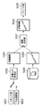
間引き器2024は、多値画像の画素を間引くことで、解像度変換を行うユニットであり、例えば、1/2、1/4、1/8等の多値画像を出力することが可能である。間引き器2024を変倍器2020と合わせて使うことで、より広範囲な画像の拡大、縮小処理を行うことができる。移動器2025は、入力された2値画像、多値画像に余白部分をつけたり、余白部分を削除したりして出力する。回転器2019、変倍器2020、色空間変換器2021、2値多値変換器2022、合成器2023、間引き器2024、移動器2025、多値2値変換器2026は、それぞれ連結して動作することが可能であり、例えばメモリ上の多値画像を画像回転、解像度変換する場合は、両処理をメモリを介さずに連結して行うことができる。
The thinning device 2024 is a unit that performs resolution conversion by thinning out pixels of a multi-valued image, and can output a multi-valued image such as 1/2, 1/4, 1/8, and the like. By using the thinning device 2024 in combination with the zooming device 2020, a wider range of image enlargement / reduction processing can be performed. The mobile unit 2025 adds a margin part to the input binary image or multi-valued image or deletes the margin part and outputs the result. A rotator 2019, a zoom 2020, a
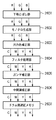
図3は、第1の実施形態で使用される画像の形式を説明するための図である。本実施形態で使用される画像の形式は、例えば特開2001−103473号公報で開示されている画像パケット構造を利用する。圧縮器2012では、ラスタ形式の画像を、図3に示すような32画素×32画素単位のパケットとして並び替え、パケット単位でJPEG圧縮を行う。
FIG. 3 is a diagram for explaining the format of an image used in the first embodiment. The image format used in the present embodiment uses, for example, an image packet structure disclosed in Japanese Patent Laid-Open No. 2001-103473. In the
図4は、第1の実施形態で使用されるパケットデータの構造を説明するための図である。圧縮器2012でJPEG圧縮を行う際には、図4に示すように、同時に、パケットにパケットの位置を示すID、色空間、QテーブルID、データ長等の情報を付加してヘッダ情報とする。さらに、文字、写真を示す2値のデータ(像域フラグ)も同様に圧縮して、JPEG情報の後に付随させる。
FIG. 4 is a diagram for explaining the structure of packet data used in the first embodiment. When JPEG compression is performed by the
一方、伸長器2013では、上記ヘッダ情報をもとにJPEG情報を展開し、ラスタ画像に並び替える。このようなパケット画像にすることで、画像回転のときにはパケット内部の画像のみを回転し、パケットIDの位置を変更することで、部分的に伸長圧縮で回転することができるため、非常に効率がよい。尚、イメージバス2010を流れる画像はすべてパケット画像になる。また、ファクシミリ送信や2値画像回転器2052、2値画像圧縮・伸長器2053等でラスタ画像が必要な場合は、パケット画像からラスタ画像への変換をソフトウェアによって行う。
On the other hand, the
図5は、第1の実施形態に係る画像処理装置200内のスキャナ画像処理部2014の細部構成を示すブロック図である。スキャナ部2015から入力されたRGB各8bitの輝度信号は、マスキング処理部2501によりCCDのフィルタ色に依存しない標準的なRGB色信号に変換される。フィルタ処理器2502ではたとえば9×9のマトリクスを使用し、画像をぼかしたり、メリハリをつける処理が行われる。
FIG. 5 is a block diagram illustrating a detailed configuration of the scanner
ヒストグラム処理部2503は、入力画像中の画像信号データのサンプリングをする処理部であり、入力画像の下地レベル判定に使用される。このモジュールでは、主走査方向、副走査方向にそれぞれ指定した開始点から終了点で囲まれた矩形領域内のRGBデータを、主走査方向、副走査方向に一定のピッチでサンプリングし、ヒストグラムを作成する。このヒストグラムは、下地とばしや、裏写り防止が指定されたときに読み出され、ヒストグラムから原稿の下地を推測し、下地とばしレベルとして、画像とともにメモリやHDDに保存、管理され、印刷や送信時の画像処理に使用される。ガンマ処理部2504では、画像全体の濃度を濃く、或いは薄くするような処理が行われる。例えば、入力画像の色空間を任意の色空間に変換したり、入力系の色味に関する補正処理を行う部分である。
The
一方、色空間変換部2505では、原稿がカラーか白黒かを判断するために変倍前の画像信号を公知のLabに変換する。このうち、a、bは色信号成分を表しており、比較器2506内の所定のレベル以上であれば有彩色、そうでなければ無彩色として、1bitの判定信号を比較器2506から出力する。カウンタ2507は、比較器2506からの出力を計測する。文字/写真判定部2508は、画像から文字エッジを抽出し、画像を文字と写真に分離する機能を有し、その出力として、文字写真判定信号が得られる。この信号も画像とともにメモリやHDDに格納され、印刷時に使用される。
On the other hand, the color
特定原稿判定部2509は、入力画像信号と判定部内部で持つパターンがどの程度一致するかを比較し、一致又は不一致という判定結果を読み出すことが可能である。そして、その判定結果に応じて、画像を加工し、紙幣や有価証券などの偽造を防止する。
The specific
図6は、第1の実施形態に係る画像処理装置200内のプリンタ画像処理部2016の細部構成を示すブロック図である。プリンタ画像処理部2016において、下地とばし部2601は、画像データの地色を飛ばし、不要な下地のカブリ除去を行う。例えば、下地とばし部2601は、3×8のマトリクス演算や、1次元LUTにより下地飛ばしを行う。モノクロ生成部2602は、カラー画像データをモノクロデータに変換する機能を有し、単色としてプリントする際に、カラー画像データ、例えばRGBデータをGray単色に変換する。例えば、RGBに任意の定数を掛け合わせ、Gray信号とする1×3のマトリクス演算から構成される。
FIG. 6 is a block diagram illustrating a detailed configuration of the printer
出力色補正部2603は、画像データを出力するプリンタ部2017の特性に合わせて色補正を行う機能を有する。例えば、出力色補正部2603は、4×8のマトリクス演算や、ダイレクトマッピングによる処理を行う。フィルタ処理部2604は、画像データの空間周波数を任意に補正する機能を有し、例えば9×9のマトリクス演算を行う処理を行う。また、ガンマ補正部2605は、出力するカラープリンタ2017の特性に合わせて、ガンマ補正を行う機能を有し、通常は1次元のLUTを用いて処理を行う。
The output
中間調補正部2608は、出力するプリンタ部2017の階調数に合わせて任意の中間調処理を行う機能を有し、2値化や32値化等の任意のスクリーン処理や、誤差拡散処理を行う。また、各処理は図示しない文字/写真判定信号によって切り替えることも可能である。ドラム間遅延メモリ2607は、CMYKの各色のドラムを持つカラープリンタにおいて、CMYKの印字タイミングをドラム間分だけずらすことで、CMYK画像を重ね合わせるためのメモリである。これにより、CMYK各色4ドラムを持つカラープリンタにおいて、画像の位置を合わせるために遅延させることができる。
The halftone correction unit 2608 has a function of performing arbitrary halftone processing in accordance with the number of gradations of the
図7は、第1の実施形態に係る画像処理装置200を実現した画像入出力デバイスの外観図である。画像入力デバイスであるスキャナ部2015は、原稿となる紙上の画像を照明し、不図示のCCDラインセンサを走査することで、ラスタイメージデータとして電気信号に変換する。尚、原稿用紙は、原稿フィーダ2701のトレイ2702にセットし、装置使用者が操作部2006から読み取り起動指示することにより、CPU2001がスキャナ部2015に指示を与え、フィーダ2071のトレイ2702から、原稿用紙を1枚ずつフィードし、原稿画像の読み取り動作を行う。
FIG. 7 is an external view of an image input / output device that implements the
画像出力デバイスであるプリンタ部2017は、ラスタイメージデータを用紙上の画像に変換する処理部であり、その方式は、感光体ドラムや感光体ベルトを用いた電子写真方式、微少ノズルアレイからインクを吐出して用紙上に直接画像を印字するインクジェット方式等があるが、どの方式でも構わない。プリント動作の起動は、CPU2001からの指示によって開始する。また、プリンタ部2017は、異なる用紙サイズや異なる用紙向きを選択することができるように複数の給紙段を持ち、例えば、それに対応した用紙カセット2703、2704、2705がある。また、排紙トレイ2706は印字し終わった用紙を受ける排紙トレイである。
The
図8は、第1の実施形態に係る画像処理装置200内の操作部2006の外観図である。図8に示すように、操作部2006上のLCD表示部2801は、LCD上にタッチパネルシート2802が貼られており、システムの操作画面及びソフトキーを表示するとともに、表示されているキーが押されると、その位置情報をCPU2001に伝える。また、スタートキー2803は、原稿画像の読み取り動作を開始する時などに用いる。スタートキー2803中央部には、例えば、緑と赤の2色LED2804があり、その色によってスタートキー2803が使える状態にあるかどうかを示す。ストップキー2805は、稼働中の動作を止める働きをする。IDキー2806は、使用者のユーザIDを入力する時に用いられる。リセットキー2807は、操作部2006からの設定を初期化する時に用いられる。
FIG. 8 is an external view of the
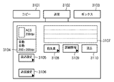
図9は、第1の実施形態に係る画像処理装置の操作部2006に表示される初期画面を示す図である。また、同図は、各画像処理機能設定後に戻ってくる標準画面でもある。図9において、コピータブ3101は、タッチされることにより、コピー設定を行うための画面への切り替えを行う。送信タブ3102は、タッチされることにより、スキャンした画像をファクシミリや電子メール等で送信する設定を行うための画面への切り替えを行う。ボックスタブ3103は、タッチされることにより、内蔵HDDにスキャン画像、PDL画像を格納する、或いは格納されたスキャン画像、PDL画像を印字、或いは送信する、或いは編集する設定を行うための画面への切り替えを行う。
FIG. 9 is a diagram illustrating an initial screen displayed on the
ウィンドウ3104は、読込設定タブ3105によって設定された画像読み込み時の設定を表示するためのウィンドウである。読込設定タブ3105は、画像読み込み時の解像度、濃度等を設定する。送信設定タブ3106は、タイマー送信時のタイマー設定、HDD或いはプリンタに印字する場合の設定等を行う。表示領域3107は、宛先表タブ3108によって指定された送信宛先の表示を行うエリアである。詳細情報タブ3109は、表示領域3107に表示された一宛先の詳細な情報の表示を行う。消去タブ3110は、表示領域3107に表示された一宛先の消去を行う。
A
図10は、図9に示す読込設定タブ3105を押下したときに表示されるポップアップウィンドウを示す図である。図10において、タブ3201は、読み取り原稿サイズをポップアップの中から選択して入力するためのタブであり、領域3202は、設定された読み取りサイズが表示される領域である。タブ3203は、原稿の読み取りモードを選択するためのタブであり、押下すると例えば、カラー/ブラック(白黒)/自動(ACS)の3種類の読み取りモードのいずれかが選択できる。尚、色モードに関しては、前述したコピー、ボックスでも同様に選択ができる。自動の読み取りモードが設定された場合は、前述したスキャナ画像処理部2014におけるカウンタ2507の計測結果が、所定値よりも小さければ白黒原稿、大きければカラー原稿と判断し、その結果を蓄積する。また、カラー読み取りモードが設定された場合はカラー画像を、ブラック読み取りモードが設定された場合には白黒画像を蓄積する。
FIG. 10 is a view showing a pop-up window displayed when the
また、タブ3204は、読み取りの解像度を指定するために、ポップアップ表示から選択した解像度の入力が可能である。スライダー3205は、原稿の読み取り濃度を調整するためのスライダーであり、例えば、9段階の調整を行うことができる。タブ3206は、例えば新聞のように下地がかぶった画像を読み込む場合に、濃度を自動的に決定するために用いられる。尚、タブ3206については、コピーでも同様の設定が可能である。
A
図11は、コピータブ3101が押下された場合に表示される画面を示す図である。図11において、領域3301はコピーできる状態が否かを示すところであり、同時に設定したコピー部数も表示される。また、タブ3302はタブ3206と同等の機能であり、下地除去を自動的にするか否かを選択するためのタブである。スライダー3303は前述のスライダー3205と同様の機能であり、例えば濃度を9段階等に分けて調整することが可能である。
FIG. 11 is a diagram showing a screen displayed when the
タブ3304は、原稿のタイプを選択するところであり、文字・写真・地図、文字、印画紙写真、印刷写真等が選択できる。タブ3305は、応用モードタブであり、縮小レイアウト(すなわち、複数枚の原稿を1枚の用紙に縮小印字する機能)や、カラーバランス(すなわち、CMYKの各色微調整)等を設定することができる。また、タブ3306は、各種フィニッシングに関する設定を行うためのタブであり、シフトソート、ステープルソート、グループソート等が設定できる。さらに、タブ3307は、両面読み込み、及び、両面印刷に関する設定を行うためのタブである。
A tab 3304 is used to select a document type, and can select text / photo / map, text, photographic paper photo, printed photo, and the like. A
図12は、図9に示すボックスタブ3103を押下したときに表示される画面の一例を示す図である。図12において、3401はHDDを論理的に区分した各フォルダタブを示す。各フォルダにはフォルダ番号があらかじめ割り振られており、3401は0番のフォルダを示している。また、フォルダ番号の横にはフォルダで使用しているディスク容量の割合が表示されている。さらに、フォルダには任意の名前をつけることができ、名前もここに表示される。3402は、HDD全体の使用量が表示される。この表示は、図12に示すように、図示であっても数値等で表示するようにしてもよい。
FIG. 12 is a diagram illustrating an example of a screen displayed when the
図13は、図12に示す画面において0番フォルダタブ3401を押下したときに表示される画面の一例を示す図である。図13において、3501及び3502は、0番フォルダに格納されている文書を示す。文書は複数のページで構成されている。尚、3501はスキャンした文書であり、スキャン文書であることを示すアイコン表示、及びHDD使用量、さらにユーザが任意に設定できる文書名表示を表示している。一方、3502はPDLから格納したPDL文書であるアイコン(すなわち、スキャン文書を示すアイコンと異なるアイコン)が表示されている。これらのアイコンを押下することで、その文書が選択されたことが、例えば反転表示等によって示される。
FIG. 13 is a diagram showing an example of a screen displayed when the
また、タブ3503は、選択された文書を送信するためのボタンである。タブ3504は、スキャナから原稿を読み込み、文書を生成するためのタブである。ボタン3505は、フォルダ内のすべての文書を選択するためのタブである。タブ3506は、選択された文書を削除するためのタブである。タブ3507は、選択された文書を印刷するためのタブである。
A tab 3503 is a button for transmitting the selected document. A
タブ3508は、選択された文書を編集するためのタブである。すなわち、タブ3508を押下することによって、例えば2つの文書を選択して、1つの文書に結合して保存したり、特定のページを削除する処理が行われる。また
タブ3509は、最後に選択された文書の詳細情報を表示するためのタブである。尚、タブ3509では、文書名以外にも解像度、原稿サイズ、カラーなどの情報を表示させることができる。
A
図14は、第1の実施形態に係る画像処理装置のソフトウェア構成を示すブロック図である。図14において、4010は、表示操作部を制御するUI制御部である。また、4020、4021及び4022は、それぞれUI制御部4010からの指示を受け、コピー動作、送信動作、ボックス画面からのスキャン、プリントを実行するコピーアプリケーション部4020、送信アプリケーション部4021、ボックスアプリケーション部4022である。また、4022は、ネットワークアプリケーション部4120からのPDLプリントデータを受け、PDLプリントジョブを投入するPDLアプリケーション部である。
FIG. 14 is a block diagram illustrating a software configuration of the image processing apparatus according to the first embodiment. In FIG. 14,
4030は、機器制御部分の機器依存部分を吸収するための共通インタフェース、4040は、共通インタフェース4030から受け取ったジョブ情報を整理し、下位層のドキュメント処理部に伝達するジョブマネージャである。
ドキュメント処理としては、(1)ローカルコピーであればスキャンマネージャ4050とプリントマネージャ4090が処理部となり、(2)リモートコピーの送信ジョブ、或いは送信ジョブであればスキャンマネージャ4050とファイルストアマネージャ4100が処理部となり、(3)リモートコピーの受信ジョブであればファイルリードマネージャ4060とプリントマネージャ4090が処理部となり、(4)LISPやPostScript等のPDLプリントではPDLマネージャ4070とプリントマネージャ4090が処理部となる。
As document processing, (1) for local copy, the
また、各ドキュメントマネージャ間の同期とり、及び各種画像処理を行うイメージマネージャ4110への画像処理の依頼はシンクマネージャ4080を介して行う。尚、スキャン、プリント時の画像処理や画像ファイルの格納はイメージマネージャ4110が行う。
Further, synchronization between the document managers and a request for image processing to the
以下では、本実施形態の画像処理装置における上記ドキュメント処理の詳細な手順について説明する。 Hereinafter, a detailed procedure of the document processing in the image processing apparatus of the present embodiment will be described.
最初に、(1)ローカルコピーのソフト処理について説明する。 First, (1) local copy software processing will be described.
まず、使用者の指示によりUI制御部4010からコピー指示とともにコピーの設定がコピーアプリケーション部4020に伝えられる。コピーアプリケーション部4020は、UI制御部4010からの情報を共通インタフェース4030を介して、機器制御を行うジョブマネージャ4040に伝える。ジョブマネージャ4040は、スキャンマネージャ4050とプリントマネージャ4090にジョブの情報を伝達する。
First, a copy setting and a copy setting are transmitted from the
次いで、スキャンマネージャ4050は、不図示のデバイスI/F(尚、デバイスI/Fは、コントローラ2000とスキャナ部2015、及びコントローラ2000とプリンタ部2017を結ぶシリアルI/F)を介して、スキャナ部2070にスキャン要求を行う。また、同時に、シンクマネージャ4080を介してイメージマネージャ4110にスキャン用の画像処理要求を出す。イメージマネージャ4110は、スキャンマネージャ4050の指示に従って、スキャナ画像処理部2014の設定を行う。そして、設定が完了した後、シンクマネージャ4080を介してスキャン準備完了を伝える。その後、スキャンマネージャ4050は、スキャナ部2070に対してスキャンを指示する。
Next, the
スキャン画像転送完了は、不図示のハードウェアからの割り込み信号によってイメージマネージャ4110に伝わる。イメージマネージャ4110からのスキャン完了を受けて、シンクマネージャ4080はスキャン完了をスキャンマネージャ4050、プリントマネージャ4090に伝える。同時に、シンクマネージャ4080は、RAM2002に蓄積された圧縮画像をHDD2004にファイル化するため、イメージマネージャ4110に指示する。イメージマネージャ4110は、指示に従ってメモリ上の画像をHDD2004に格納する。尚、文字/写真判定信号も格納される。また、画像の付随情報として不図示のSRAMにカラー判定/白黒判定結果、下地とばしを行うための下地とばしレベル、画像入力元としてスキャン画像、色空間RGBを格納する。
The completion of the scan image transfer is transmitted to the
また、HDD2004への格納が終了し、スキャナ部2070からのスキャン完了を受けた場合、イメージマネージャ4110は、シンクマネージャ4080を介してスキャンマネージャ4050にファイル化終了を通知する。スキャンマネージャ4050は、ジョブマネージャ4040に対して終了通知を返し、ジョブマネージャ4040は、共通インタフェース4030を介してコピーアプリケーション部4020へ返す。
In addition, when the storage in the
プリントマネージャ4090は、メモリに画像が入った時点でデバイスI/Fを介して、プリンタ部2095に印刷要求を出す。同時に、シンクマネージャ4080にプリント画像処理要求を行う。シンクマネージャ4080は、プリントマネージャ4090から要求を受けた場合、画像処理設定をイメージマネージャ4110に依頼する。イメージマネージャ4110は、前述した画像の付随情報に従って、プリンタ画像処理部2015の設定を行い、シンクマネージャ4080を介して、プリントマネージャ4090にプリント準備完了を伝える。プリントマネージャ4090は、プリンタに対して印刷指示を出す。
The
プリント画像転送完了は不図示のハードウェアからの割り込み信号によってイメージマネージャ4110に伝わる。イメージマネージャ4110からのプリント完了を受けて、シンクマネージャ4080は、プリント完了をプリントマネージャ4090に伝える。プリントマネージャ4090は、プリンタ部からの排紙完了を受け、ジョブマネージャ4040に対して終了通知を返す。ジョブマネージャ4040は、共通インタフェース4030を介して、コピーアプリケーション部4020へ返す。コピーアプリケーション部4020は、スキャン、プリントが終了した後、ジョブ終了をUI制御部4010に通知する。
The completion of print image transfer is transmitted to the
次に、(2)リモートコピーのスキャンジョブ、送信ジョブの場合について説明する。 Next, (2) the case of a remote copy scan job and transmission job will be described.
まず、プリントマネージャ4090に代わってストアマネージャ4100がジョブマネージャ4040からの要求を受ける。そして、スキャン画像をHDDに格納し終わった時点で、シンクマネージャ4080から格納完了通知を受け、それを共通インタフェース4030を介して、リモートコピーの場合はコピーアプリケーション部4020に、送信ジョブの場合は送信アプリケーション部4021に通知する。コピーアプリケーション部4020及び送信アプリケーション4021はこの通知の後、ネットワークアプリケーション4420に対してHDDに格納されたファイルの送信を依頼する。
First, the store manager 4100 receives a request from the
次に、依頼を受けたネットワークアプリケーション4420がファイルを送信する。ネットワークアプリケーション4420は、ジョブ開始時にコピーアプリケーション部4020からコピーに関する設定情報を受け、それをリモート側の機器に通知する。ネットワークアプリケーション4420は、リモートコピーの場合、機器固有の通信プロトコルを使用して送信を行う。また、送信ジョブの場合は、FTP、SMBのような標準的なファイル転送プロトコルを使用する。
Next, the network application 4420 that has received the request transmits the file. The network application 4420 receives setting information related to copying from the
ファクシミリ送信する場合は、ファイル格納後、送信アプリケーション4021から共通インタフェース4030、ジョブマネージャ4040を介して、ファクシミリ(FAX)マネージャ4041に送信が指示される。FAXマネージャ4041は、モデム2050を介して、相手機器とネゴシエーションし、必要な画像処理(例えば、カラー画像の白黒変換、多値2値変換、回転、変倍等)をイメージマネージャ4110に依頼し、変換後の画像をモデム2050を使って送信する。
In the case of facsimile transmission, transmission is instructed from the
また、送信先にプリンタがある場合、送信アプリケーションは、共通インタフェース4030を介して、プリントジョブとしてプリントの指示を行う。そのときの動作は、以下で説明するリモートコピーのプリントジョブの場合と同様である。また、送信宛先が機器内のボックス宛先になっているときは、ファイルストアマネージャ4100によって機器内のファイルシステムに格納する。
When there is a printer at the transmission destination, the transmission application issues a print instruction as a print job via the
一方、FAX受信時は、FAXマネージャ4041がモデム2050を使って画像を受信し、画像ファイルとしてHDD2004に格納する。HDD2004格納後にボックスアプリケーション4021に通知すると、ボックスアプリケーション4021から受信プリントの指示が、共通インタフェース4030を介して、ジョブマネージャ4040になされる。その後は、通常のボックスプリントジョブと同じ動作になるため省略する。
On the other hand, at the time of FAX reception, the
次いで、(3)リモートコピーのプリントジョブの場合について説明する。 Next, (3) the case of a remote copy print job will be described.
この場合は、送信側からの画像をネットワークアプリケーション4420がHDDに保存するとともに、コピーアプリケーション部4020に対してジョブを発行する。コピーアプリケーション部4020は、共通インタフェース4030を介して、ジョブマネージャ4040にプリントジョブを投入する。ローカルコピーとは異なり、スキャンマネージャ4050に代わってファイルリードマネージャ4060が、ジョブマネージャ4040からの要求を受ける。そして、受信画像をHDDからメモリに展開するための要求をシンクマネージャ4080を介して、イメージマネージャ4110に行う。
In this case, the network application 4420 saves the image from the transmission side in the HDD and issues a job to the
また、イメージマネージャ4110はメモリに画像を展開する。イメージマネージャ4110は展開が終了した時点で、展開終了をシンクマネージャ4080を経由して、ファイルリードマネージャ4060とプリントマネージャ4090に伝える。プリントマネージャ4090は、メモリに画像が入った時点でデバイスI/Fを介して、プリンタ2017にジョブマネージャ4040から指示された給紙段、若しくはその用紙サイズを有する段等を選択し、印刷要求を指す。尚、自動用紙の場合には、画像サイズから給紙段を決定し印刷要求を出すようにする。
The
イメージマネージャ4110は、同時にシンクマネージャ4080にプリント画像処理要求を行う。シンクマネージャ4080は、プリントマネージャ4090から要求を受けた後、プリント画像処理設定をイメージマネージャ4110に依頼する。尚、この場合に例えば最適サイズ用紙がなくなり、回転が必要になれば別途回転指示も依頼する。そして、回転指示があった場合には、イメージマネージャ4110が画像回転部2019を使って画像を回転する。
The
さらに、イメージマネージャ4110は、プリンタ画像処理部2090の設定を行い、シンクマネージャ4080を介して、プリントマネージャ4090にプリント準備完了を伝える。プリントマネージャ4090は、プリンタに対して印刷指示を出す。プリント画像転送完了は、不図示のハードウェアからの割り込み信号によってイメージマネージャ4110に伝えられる。イメージマネージャ4110からのプリント完了を受けてシンクマネージャ4080は、プリント完了をファイルリードマネージャ4060とプリントマネージャ4090に伝える。そして、ファイルリードマネージャ4060は、終了通知をジョブマネージャ4040に返す。
Further, the
プリントマネージャ4090は、プリンタ部からの排紙完了を受け、ジョブマネージャ4040に対して終了通知を返す。ジョブマネージャ4040は、共通インタフェース4030を介して、コピーアプリケーション部4020へ終了通知を返す。コピーアプリケーション部4020は、スキャン、プリントが終了した後、ジョブ終了をUI制御部4010に通知する。
In response to the completion of paper discharge from the printer unit, the
次いで、(4)PDLデータ展開格納ジョブの場合について説明する。 Next, the case of (4) a PDL data development storage job will be described.
この場合、まず、PDLプリントを投入したホストPCからの要求が、ネットワークアプリケーション4120を経由してPDLアプリケーション4023に伝達される。PDLアプリケーション4023が、PDLデータ展開格納ジョブを共通インタフェース4030を介して、ジョブマネージャ4040に指示する。このとき、PDLマネージャ4070とストアマネージャ4100がジョブマネージャ4040からの要求を受ける。尚、画像のRIPが終了した後の画像入力する部分に関しては、前述のスキャンジョブと同様である。
In this case, first, a request from the host PC that has input the PDL print is transmitted to the
そして、メモリ上の画像を文字/写真判定信号を含めてHDD2004に格納する。この際、画像の付随情報として不図示のSRAMに、カラー/白黒情報、画像入力元としてPDL画像、色空間CMYK若しくはRGBを格納しておく。PDL画像をHDD2004に格納し終わった時点で、シンクマネージャ4080から格納完了通知を受け、それを共通インタフェース4030を介して、PDLアプリケーション4023に通知する。PDLアプリケーション4023は、この通知の後、ネットワークアプリケーション4420にHDD2004に格納完了を通知し、PDLプリントを投入したホストPCへこの情報が伝達される。また、PDLプリントジョブの場合には、PDLマネージャ4070とプリントマネージャによって、メモリ上に展開された画像を印字する。
Then, the image on the memory is stored in the
PDL展開され、格納された画像のプリントは、UIで印刷指示された格納文書をボックスアプリケーション部4022に対してプリントジョブとして発行する。ボックスアプリケーション部4022は、共通インタフェース4030を介して、ジョブマネージャ4040にプリントジョブを投入する。ローカルコピーとは異なり、スキャンマネージャ4050に代わってファイルリードマネージャ4060がジョブマネージャ4040からの要求を受ける。そして、印刷指示された画像をHDD2004からメモリに展開するための要求をシンクマネージャ4080を介して、イメージマネージャ4110に行う。この後の動作は、リモートコピーのプリントジョブで説明した動作と同様のため省略する。
For printing an image developed and stored in PDL, a stored document instructed to be printed on the UI is issued to the
図15は、本発明の第1の実施形態に係る画像合成処理を行う画像処理装置の構成を示すブロック図である。図15に示すように、スキャナ部5001又はPDL展開部5002から入力される画像は、画像入力処理部5003によって選択的に入力され、ここで既知の入力画像処理が行われる。ここでの処理には、入力画像が白黒画像であるかカラー画像であるかを自動判別する自動白黒カラー判定処理も含まれる。入力画像処理が施された原稿画像5004は、画像メモリ上に格納される。一方、原稿画像5004に合成されるウォーターマーク画像5006は、ハードディスク5005に格納されており、合成処理を行うためにメモリ上に展開される。そして、画像合成部5007は、原稿画像5004とウォーターマーク画像5006とを合成し、合成画像5008を出力する。そして、プリンタ部5009は、合成画像を印字出力する。
FIG. 15 is a block diagram showing a configuration of an image processing apparatus that performs image composition processing according to the first embodiment of the present invention. As shown in FIG. 15, an image input from the
図16は、スキャン画像とハードディスクに予め格納された画像とを合成する画像合成処理を例にとって、本発明の第1の実施形態に係る画像処理装置による画像合成処理手順を説明するためのフローチャートである。 FIG. 16 is a flowchart for explaining an image composition processing procedure by the image processing apparatus according to the first embodiment of the present invention, taking as an example an image composition process for compositing a scanned image and an image stored in the hard disk in advance. is there.
まず、操作部2006から画像合成設定を行い、コピースタートキー2014の押下により、合成コピーを開始する(ステップS5000)。次に、原稿画像をスキャンし、入力画像処理を行った画像をメモリに格納する(ステップS5001)。このとき、スキャン画像中のカラー画素数を計数する入力画像処理が行われる。そして、ステップS5001で計数した原稿画像中のカラー画素数を元に、原稿画像がカラー画像であるか白黒画像であるかの判定を行い、スキャン画像の色モードを決定する(ステップS5002)。
First, image composition setting is performed from the
一方、スキャン画像と合成する合成用画像をハードディスクからメモリに読み出す(ステップS5011)。尚、読み出す際に、合成用画像データ自身と合わせて記憶されている当該合成用画像の色モードを読み出し、合成用画像の色モードを確定する(ステップS5012)。ここで、合成用画像の色モードについては、あらかじめカラーモード及び白黒モードとして設定されたものと、前述した原稿画像の判定と同様に、自動判定の結果、カラーモード又は白黒モードと判定された場合が存在する。そこで、ハードディスクには、これらの4つのパターンで合成用画像の色モードが記憶されている。このため、あらかじめ、合成用画像を生成し、合成用画像の色モードの設定又は合成用画像の色モードの判定を行い、設定された色モードでハードディスクに保存する、又は、判定された色モードとしてハードディスクに保存しておく。 On the other hand, a synthesis image to be synthesized with the scanned image is read from the hard disk to the memory (step S5011). At the time of reading, the color mode of the image for synthesis stored together with the image data for synthesis itself is read, and the color mode of the image for synthesis is determined (step S5012). Here, as for the color mode of the image for composition, when the color mode or the black and white mode is determined as a result of automatic determination as in the case of the determination of the original image and the color mode and the black and white mode previously set. Exists. Therefore, the color mode of the composition image is stored in the hard disk in these four patterns. For this reason, an image for synthesis is generated in advance, the color mode of the image for synthesis is set or the color mode of the image for synthesis is determined, and stored in the hard disk in the set color mode, or the determined color mode Save it to your hard disk as
そして、スキャン画像と合成用画像の色モードが共に確定した時点で、合成出力画像の色モードの判定を行う(ステップS5003)。そして、スキャン画像と合成用画像の合成処理を行う(ステップS5004)。次いで、出力された合成画像に対して、ステップS5003で確定した合成出力画像の色モードに対応する色空間に変換するための色空間変換処理を行う(ステップS5005)。そして、色空間変換処理後の画像をプリント出力し(ステップS5006)、合成コピー処理が終了する(ステップS5007)。 Then, when the color modes of both the scan image and the composition image are determined, the color mode of the composite output image is determined (step S5003). Then, a composition process of the scan image and the composition image is performed (step S5004). Next, color space conversion processing for converting the output composite image into a color space corresponding to the color mode of the composite output image determined in step S5003 is performed (step S5005). Then, the image after the color space conversion process is printed out (step S5006), and the composite copy process ends (step S5007).
図17は、第1の実施形態における合成色モード優先設定手段により入力画像優先設定がなされたときの合成画像の色モードを示す図である。本実施形態では、図17に示すように、入力画像(スキャン画像)優先設定がなされたであって、原稿画像の色モードにカラーが選択されている場合には、合成用画像の色モードが何であるかによらず、合成画像の色モードは原稿画像の色モードであるカラーとなる。反対に、原稿画像の色モードに白黒が選択された場合には、合成用画像の色モードが何であるかによらず、合成画像の色モードは白黒となる。 FIG. 17 is a diagram illustrating the color mode of the composite image when the input image priority setting is performed by the composite color mode priority setting unit according to the first embodiment. In the present embodiment, as shown in FIG. 17, when the input image (scanned image) priority setting is made and the color is selected as the color mode of the document image, the color mode of the image for synthesis is set. Regardless of what it is, the color mode of the composite image is the color that is the color mode of the original image. On the other hand, when black and white is selected as the color mode of the original image, the color mode of the composite image is black and white regardless of what the color mode of the composite image is.
また、原稿画像の色モードに自動カラー選択(ACS)が設定されている場合は、白黒カラー判定結果に応じて合成画像の色モードが選択される。すなわち、原稿画像がカラーと判定された時には、合成用画像の色モードが何であるかによらず、合成画像の色モードはカラーとなる。また、原稿画像が白黒と判定された時には、合成用画像の色モードが何であるかによらず、合成画像の色モードは白黒となる。 When automatic color selection (ACS) is set as the color mode of the original image, the color mode of the composite image is selected according to the monochrome color determination result. That is, when the original image is determined to be color, the color mode of the composite image is color regardless of what the color mode of the composite image is. When the original image is determined to be black and white, the color mode of the composite image is black and white regardless of the color mode of the composite image.
図18は、第1の実施形態における合成色モード優先設定手段により合成画像優先設定がなされたときの合成画像の色モードを示す図である。図18に示すように、合成画像優先設定がなされた場合、原稿画像又は合成画像の色モードのいずれか一方にカラーが選択されている場合、及び自動カラー選択(ACS)でカラー判定の場合、合成画像の色モードは合成画像の色モードであるカラーとなる。反対に、原稿画像及び合成画像の両方の色モードとして白黒、又は、自動カラー選択(ACS)で白黒が選択されている場合は、合成画像の色モードは白黒となる。 FIG. 18 is a diagram illustrating a color mode of a composite image when composite image priority setting is performed by the composite color mode priority setting unit according to the first embodiment. As shown in FIG. 18, when the composite image priority setting is made, when the color is selected in one of the color modes of the original image or the composite image, and when color determination is performed by automatic color selection (ACS), The color mode of the composite image is a color that is the color mode of the composite image. On the other hand, when monochrome is selected as the color mode for both the original image and the synthesized image, or when monochrome is selected by automatic color selection (ACS), the color mode of the synthesized image is monochrome.
<その他の実施形態>
尚、本発明は、複数の機器(例えば、ホストコンピュータ、インタフェース機器、リーダ、プリンタ等)から構成されるシステムに適用しても、一つの機器からなる装置(例えば、複写機、ファクシミリ装置等)に適用してもよい。
<Other embodiments>
Note that the present invention can be applied to a system composed of a plurality of devices (for example, a host computer, an interface device, a reader, a printer, etc.), but a device (for example, a copier, a facsimile machine, etc.) composed of a single device. You may apply to.
また、本発明の目的は、前述した実施形態の機能を実現するソフトウェアのプログラムコードを記録した記録媒体(又は記憶媒体)を、システム或いは装置に供給し、そのシステム或いは装置のコンピュータ(又はCPUやMPU)が記録媒体に格納されたプログラムコードを読み出し実行することによっても、達成されることは言うまでもない。この場合、記録媒体から読み出されたプログラムコード自体が前述した実施形態の機能を実現することになり、そのプログラムコードを記録した記録媒体は本発明を構成することになる。また、コンピュータが読み出したプログラムコードを実行することにより、前述した実施形態の機能が実現されるだけでなく、そのプログラムコードの指示に基づき、コンピュータ上で稼働しているオペレーティングシステム(OS)等が実際の処理の一部又は全部を行い、その処理によって前述した実施形態の機能が実現される場合も含まれることは言うまでもない。 Also, an object of the present invention is to supply a recording medium (or storage medium) on which a program code of software that realizes the functions of the above-described embodiments is recorded to a system or apparatus, and the computer (or CPU or CPU) of the system or apparatus. Needless to say, this can also be achieved when the MPU) reads and executes the program code stored in the recording medium. In this case, the program code itself read from the recording medium realizes the functions of the above-described embodiment, and the recording medium on which the program code is recorded constitutes the present invention. Further, by executing the program code read by the computer, not only the functions of the above-described embodiments are realized, but also an operating system (OS) or the like running on the computer based on an instruction of the program code. It goes without saying that a case where the function of the above-described embodiment is realized by performing part or all of the actual processing and the processing is included.
さらに、記録媒体から読み出されたプログラムコードが、コンピュータに挿入された機能拡張カードやコンピュータに接続された機能拡張ユニットに備わるメモリに書き込まれた後、そのプログラムコードの指示に基づき、その機能拡張カードや機能拡張ユニットに備わるCPU等が実際の処理の一部又は全部を行い、その処理によって前述した実施形態の機能が実現される場合も含まれることは言うまでもない。 Further, after the program code read from the recording medium is written into a memory provided in a function expansion card inserted into the computer or a function expansion unit connected to the computer, the function expansion is performed based on the instruction of the program code. It goes without saying that the case where the CPU or the like provided in the card or the function expansion unit performs part or all of the actual processing and the functions of the above-described embodiments are realized by the processing.
本発明を上記記録媒体に適用する場合、その記録媒体には、先に説明したフローチャートに対応するプログラムコードが格納されることになる。 When the present invention is applied to the recording medium, program code corresponding to the flowchart described above is stored in the recording medium.
5001 スキャナ部
5002 PDL展開部
5003 画像入力処理部
5004 原稿画像
5005 ハードディスク
5006 ウォーターマーク画像
5007 画像合成部
5008 合成画像
5009 プリンタ部
5001
Claims (5)
合成用画像のカラー画素数に基づいて、合成用画像の色モードを決定する合成用画像色モード決定手段と、
前記原稿画像色モード決定手段で原稿画像の色モードが白黒モードであると決定された場合に、前記合成用画像の色モードにかかわらず、前記原稿画像と前記合成用画像とを合成して得られる合成画像の色モードを白黒モードに設定する第1設定手段と、
前記合成用画像色モード決定手段で合成用画像の色モードがカラーモードであると決定された場合に、前記原稿画像の色モードにかかわらず、前記合成画像の色モードをカラーモードに設定する第2設定手段と、
前記原稿画像と前記合成用画像とを合成する合成手段と、
前記合成手段での合成により得られた合成画像を、合成画像に対して設定された色モードで色空間変換処理する色空間変換処理手段と、
を有することを特徴とする画像処理装置。 A document image color mode determining means for determining a color mode of the document image based on the number of color pixels in the document image;
An image color mode determining unit for combining that determines a color mode of the image for combining based on the number of color pixels of the image for combining;
When the original image color mode determining means determines that the color mode of the original image is the black and white mode, the original image and the image for synthesis are obtained regardless of the color mode of the image for synthesis. First setting means for setting the color mode of the synthesized image to black and white mode;
When the composition image color mode determining means determines that the color mode of the composition image is the color mode, the color mode of the composition image is set to the color mode regardless of the color mode of the original image. 2 setting means;
Combining means for combining the document image and the combining image;
Color space conversion processing means for performing color space conversion processing on a composite image obtained by the synthesis in the synthesis means in a color mode set for the composite image;
An image processing apparatus comprising:
合成用画像のカラー画素数に基づいて、合成用画像の色モードを決定する合成用画像色モード決定工程と、
前記原稿画像色モード決定工程で原稿画像の色モードが白黒モードであると決定された場合に、前記合成用画像の色モードにかかわらず、前記原稿画像と前記合成用画像とを合成して得られる合成画像の色モードを白黒モードに設定する第1設定工程と、
前記合成用画像色モード決定工程で合成用画像の色モードがカラーモードであると決定された場合に、前記原稿画像の色モードにかかわらず、前記合成画像の色モードをカラーモードに設定する第2設定工程と、
前記原稿画像と前記合成用画像とを合成する合成工程と、
前記合成工程での合成により得られた合成画像を、合成画像に対して設定された色モードで色空間変換処理する色空間変換処理工程と、
を有することを特徴とする画像処理方法。 A document image color mode determination step for determining a color mode of the document image based on the number of color pixels in the document image;
A composition image color mode determination step for determining a color mode of the composition image based on the number of color pixels of the composition image;
When the color mode of the document image is determined to be the monochrome mode in the document image color mode determination step, the document image is obtained by combining the document image and the composition image regardless of the color mode of the composition image. A first setting step of setting the color mode of the composite image to be monochrome mode;
When the color mode of the composite image is determined to be the color mode in the composite image color mode determination step, the color mode of the composite image is set to the color mode regardless of the color mode of the document image. 2 setting steps;
A synthesis step of synthesizing the original image and the image for synthesis;
A color space conversion processing step of performing color space conversion processing on the composite image obtained by the synthesis in the synthesis step in a color mode set for the composite image;
An image processing method comprising:
Priority Applications (3)
| Application Number | Priority Date | Filing Date | Title |
|---|---|---|---|
| JP2003337977A JP4125208B2 (en) | 2003-09-29 | 2003-09-29 | Image processing apparatus and image processing method |
| US10/953,149 US7599078B2 (en) | 2003-09-29 | 2004-09-28 | Image processing apparatus and image processing method |
| US12/549,705 US8004698B2 (en) | 2003-09-29 | 2009-08-28 | Image forming apparatus for combining a scanned image with other image data and printing the combined image in black and white or color based on a set mode |
Applications Claiming Priority (1)
| Application Number | Priority Date | Filing Date | Title |
|---|---|---|---|
| JP2003337977A JP4125208B2 (en) | 2003-09-29 | 2003-09-29 | Image processing apparatus and image processing method |
Publications (3)
| Publication Number | Publication Date |
|---|---|
| JP2005109691A JP2005109691A (en) | 2005-04-21 |
| JP2005109691A5 JP2005109691A5 (en) | 2006-11-16 |
| JP4125208B2 true JP4125208B2 (en) | 2008-07-30 |
Family
ID=34373297
Family Applications (1)
| Application Number | Title | Priority Date | Filing Date |
|---|---|---|---|
| JP2003337977A Expired - Fee Related JP4125208B2 (en) | 2003-09-29 | 2003-09-29 | Image processing apparatus and image processing method |
Country Status (2)
| Country | Link |
|---|---|
| US (2) | US7599078B2 (en) |
| JP (1) | JP4125208B2 (en) |
Families Citing this family (27)
| Publication number | Priority date | Publication date | Assignee | Title |
|---|---|---|---|---|
| US7944593B2 (en) * | 2004-09-09 | 2011-05-17 | Infoprint Solutions Company, Llc | Method and apparatus for efficient processing of color conversion |
| JP3928732B2 (en) * | 2005-01-06 | 2007-06-13 | コニカミノルタビジネステクノロジーズ株式会社 | Color image forming apparatus and image storage apparatus |
| JP2007013607A (en) * | 2005-06-30 | 2007-01-18 | Canon Inc | Image processing device, control method for image processing device, and program and storage medium |
| JP2007174069A (en) * | 2005-12-20 | 2007-07-05 | Canon Inc | Image communication device, image communication method, program, and storage medium |
| JP4259561B2 (en) * | 2006-09-29 | 2009-04-30 | ブラザー工業株式会社 | Print control apparatus and program |
| JP4323511B2 (en) * | 2006-12-07 | 2009-09-02 | シャープ株式会社 | Image processing device |
| JP5480462B2 (en) * | 2007-02-27 | 2014-04-23 | 富士ゼロックス株式会社 | Document processing program, document processing apparatus, and document processing system |
| KR101340562B1 (en) * | 2007-04-10 | 2013-12-11 | 삼성전자주식회사 | Apparatus of copying and user interface method thereof |
| JP4360418B2 (en) * | 2007-04-19 | 2009-11-11 | コニカミノルタビジネステクノロジーズ株式会社 | Image processing apparatus, viewer, image processing program, and image processing system |
| US7979618B2 (en) * | 2007-07-12 | 2011-07-12 | Samsung Electronics Co., Ltd. | Image forming apparatus and control method thereof |
| JP2009111904A (en) * | 2007-10-31 | 2009-05-21 | Ricoh Co Ltd | Device for processing images and method of executing applications |
| JP4678605B2 (en) * | 2007-12-03 | 2011-04-27 | コニカミノルタビジネステクノロジーズ株式会社 | Image forming apparatus and count control method |
| JP2009284062A (en) * | 2008-05-20 | 2009-12-03 | Kyocera Mita Corp | Image processing apparatus, image forming apparatus |
| US20090310149A1 (en) * | 2008-06-13 | 2009-12-17 | Kyocera Mita Corporation | Image forming apparatus |
| JP5199761B2 (en) * | 2008-07-11 | 2013-05-15 | キヤノン株式会社 | Information processing apparatus, image input apparatus, document distribution system, and control method therefor |
| WO2010045406A2 (en) * | 2008-10-15 | 2010-04-22 | The Regents Of The University Of California | Camera system with autonomous miniature camera and light source assembly and method for image enhancement |
| JP5039736B2 (en) * | 2009-03-24 | 2012-10-03 | キヤノン株式会社 | Image processing apparatus, control method, and program |
| JP5121786B2 (en) * | 2009-07-10 | 2013-01-16 | キヤノン株式会社 | Image processing method, image processing apparatus, and program |
| JP5071532B2 (en) * | 2010-07-09 | 2012-11-14 | ブラザー工業株式会社 | Scanner device |
| JP5269029B2 (en) * | 2010-10-04 | 2013-08-21 | シャープ株式会社 | Image processing apparatus, image forming apparatus, image processing method, computer program, and recording medium |
| JP5138020B2 (en) * | 2010-11-12 | 2013-02-06 | シャープ株式会社 | Image processing apparatus, image forming apparatus, image processing method, computer program, and recording medium |
| US8730543B2 (en) | 2012-06-19 | 2014-05-20 | Xerox Corporation | Detecting common errors in repeated scan workflows by use of job profile metrics |
| US8736929B2 (en) | 2012-06-19 | 2014-05-27 | Xerox Corporation | Recording and recalling of scan build job and scan batch job settings |
| JP5501425B2 (en) * | 2012-10-23 | 2014-05-21 | キヤノン株式会社 | Image processing method, image processing apparatus, and program |
| KR20140067510A (en) * | 2012-11-26 | 2014-06-05 | 삼성전자주식회사 | Image forming apparatus, method for image forming, and computer-readable recording medium |
| TWI536799B (en) * | 2014-10-29 | 2016-06-01 | 虹光精密工業股份有限公司 | Smart copy apparatus |
| JP2023067164A (en) * | 2021-10-29 | 2023-05-16 | キヤノン株式会社 | Image processing apparatus and image processing method |
Family Cites Families (22)
| Publication number | Priority date | Publication date | Assignee | Title |
|---|---|---|---|---|
| US5028992A (en) * | 1988-08-25 | 1991-07-02 | Ricoh Company, Ltd. | Image combining apparatus for a digital color copier |
| US5381248A (en) * | 1990-05-04 | 1995-01-10 | Canon Kabushiki Kaisha | Image processing apparatus |
| JP3155541B2 (en) * | 1990-06-20 | 2001-04-09 | キヤノン株式会社 | Image forming apparatus and control method thereof |
| US5706368A (en) * | 1990-12-26 | 1998-01-06 | Canon Kabushiki Kaisha | Image processing apparatus and method having detection of background color and encoding of color image data |
| JP3136647B2 (en) * | 1991-06-03 | 2001-02-19 | 株式会社日立製作所 | Input color mode display selection method |
| JP2719644B2 (en) * | 1992-09-30 | 1998-02-25 | 大日本スクリーン製造株式会社 | Turnip treatment method |
| JP2720924B2 (en) * | 1993-09-21 | 1998-03-04 | 富士ゼロックス株式会社 | Image signal encoding device |
| US5966468A (en) * | 1994-08-04 | 1999-10-12 | Canon Kabushiki Kaisha | Image processing apparatus and method therefor |
| US5815645A (en) * | 1996-07-29 | 1998-09-29 | Eastman Kodak Company | Method of combining two digital images |
| JPH10341341A (en) * | 1997-06-06 | 1998-12-22 | Minolta Co Ltd | Image processor |
| JPH1175050A (en) * | 1997-08-29 | 1999-03-16 | Fujitsu Ltd | Image data synthesizing device |
| JP2001036751A (en) * | 1999-05-20 | 2001-02-09 | Canon Inc | Picture processor, its method and storage medium storing computer readable program |
| JP3722467B2 (en) * | 2000-12-28 | 2005-11-30 | 京セラミタ株式会社 | Image forming apparatus |
| JP2002247390A (en) * | 2001-02-22 | 2002-08-30 | Ricoh Co Ltd | Image reproduction method and device, program, and computer-readable record medium |
| JP2003163801A (en) * | 2001-11-26 | 2003-06-06 | Fuji Xerox Co Ltd | Apparatus, method, and program for image processing, and storage medium |
| US20030202198A1 (en) * | 2002-04-24 | 2003-10-30 | North Hannah Catharine | Printing system |
| JP4170110B2 (en) * | 2002-04-26 | 2008-10-22 | シャープ株式会社 | Liquid crystal display device and manufacturing method thereof |
| US7110137B2 (en) * | 2002-04-30 | 2006-09-19 | Microsoft Corporation | Mixed raster content files |
| US7307758B2 (en) * | 2002-11-14 | 2007-12-11 | Kabushiki Kaisha Toshiba | Image forming apparatus and image forming method |
| JP4095530B2 (en) * | 2003-10-01 | 2008-06-04 | キヤノン株式会社 | Image processing apparatus and method |
| JP4405878B2 (en) * | 2004-09-02 | 2010-01-27 | キヤノン株式会社 | Image processing apparatus, image processing method, program, and storage medium |
| JP2006101444A (en) * | 2004-09-30 | 2006-04-13 | Canon Inc | Image forming device and control method therefor |
-
2003
- 2003-09-29 JP JP2003337977A patent/JP4125208B2/en not_active Expired - Fee Related
-
2004
- 2004-09-28 US US10/953,149 patent/US7599078B2/en active Active
-
2009
- 2009-08-28 US US12/549,705 patent/US8004698B2/en active Active
Also Published As
| Publication number | Publication date |
|---|---|
| JP2005109691A (en) | 2005-04-21 |
| US20090316212A1 (en) | 2009-12-24 |
| US7599078B2 (en) | 2009-10-06 |
| US8004698B2 (en) | 2011-08-23 |
| US20050068586A1 (en) | 2005-03-31 |
Similar Documents
| Publication | Publication Date | Title |
|---|---|---|
| JP4125208B2 (en) | Image processing apparatus and image processing method | |
| US7532348B2 (en) | Image input/output control method and image input/output apparatus | |
| JP3797669B2 (en) | Image forming apparatus and image forming method | |
| EP1708479B1 (en) | Image processing apparatus and its method | |
| JP6147020B2 (en) | Image processing apparatus, image processing method, and program | |
| JP2007116458A (en) | Image input/output device, image data input/output method, and program | |
| JP2004090423A (en) | Image formation device and its processing method | |
| JP2006180343A (en) | Image input-output device | |
| JP2006333200A (en) | Color image input/output apparatus | |
| JP6373448B2 (en) | Image processing apparatus, image processing method, and program | |
| JP2006036423A (en) | Image processing device | |
| JP2006287707A (en) | Image processor | |
| JP2006166134A (en) | Image communication equipment, its control method, program, and storage medium | |
| JP2007129428A (en) | Image processor and image processing method | |
| JP2006157806A (en) | Image processor | |
| JP2005110020A (en) | Image input-output apparatus and memory control method and image forming apparatus | |
| JP2006240151A (en) | Image output unit | |
| JP2007030352A (en) | Multi-color image printer | |
| JP2006211219A (en) | Image output apparatus | |
| JP2007028064A (en) | Image forming apparatus | |
| JP2007013841A (en) | Color image input/output device | |
| JP2005275857A (en) | Color image input and output device | |
| JP2007060264A (en) | Image input-output apparatus | |
| JP2007036793A (en) | Color image processing system | |
| JP2006041972A (en) | Image processor, display control method, storage medium stored with computer-readable program, and program |
Legal Events
| Date | Code | Title | Description |
|---|---|---|---|
| A521 | Request for written amendment filed |
Free format text: JAPANESE INTERMEDIATE CODE: A523 Effective date: 20060929 |
|
| A621 | Written request for application examination |
Free format text: JAPANESE INTERMEDIATE CODE: A621 Effective date: 20060929 |
|
| A977 | Report on retrieval |
Free format text: JAPANESE INTERMEDIATE CODE: A971007 Effective date: 20080110 |
|
| A131 | Notification of reasons for refusal |
Free format text: JAPANESE INTERMEDIATE CODE: A131 Effective date: 20080116 |
|
| A521 | Request for written amendment filed |
Free format text: JAPANESE INTERMEDIATE CODE: A523 Effective date: 20080317 |
|
| TRDD | Decision of grant or rejection written | ||
| A01 | Written decision to grant a patent or to grant a registration (utility model) |
Free format text: JAPANESE INTERMEDIATE CODE: A01 Effective date: 20080414 |
|
| A01 | Written decision to grant a patent or to grant a registration (utility model) |
Free format text: JAPANESE INTERMEDIATE CODE: A01 |
|
| A61 | First payment of annual fees (during grant procedure) |
Free format text: JAPANESE INTERMEDIATE CODE: A61 Effective date: 20080507 |
|
| R150 | Certificate of patent or registration of utility model |
Free format text: JAPANESE INTERMEDIATE CODE: R150 |
|
| FPAY | Renewal fee payment (event date is renewal date of database) |
Free format text: PAYMENT UNTIL: 20110516 Year of fee payment: 3 |
|
| FPAY | Renewal fee payment (event date is renewal date of database) |
Free format text: PAYMENT UNTIL: 20120516 Year of fee payment: 4 |
|
| FPAY | Renewal fee payment (event date is renewal date of database) |
Free format text: PAYMENT UNTIL: 20120516 Year of fee payment: 4 |
|
| FPAY | Renewal fee payment (event date is renewal date of database) |
Free format text: PAYMENT UNTIL: 20130516 Year of fee payment: 5 |
|
| FPAY | Renewal fee payment (event date is renewal date of database) |
Free format text: PAYMENT UNTIL: 20140516 Year of fee payment: 6 |
|
| LAPS | Cancellation because of no payment of annual fees |