JP3565802B2 - Vehicle window sensor - Google Patents
Vehicle window sensor Download PDFInfo
- Publication number
- JP3565802B2 JP3565802B2 JP2001213348A JP2001213348A JP3565802B2 JP 3565802 B2 JP3565802 B2 JP 3565802B2 JP 2001213348 A JP2001213348 A JP 2001213348A JP 2001213348 A JP2001213348 A JP 2001213348A JP 3565802 B2 JP3565802 B2 JP 3565802B2
- Authority
- JP
- Japan
- Prior art keywords
- sensor
- lens
- light
- vehicle window
- window glass
- Prior art date
- Legal status (The legal status is an assumption and is not a legal conclusion. Google has not performed a legal analysis and makes no representation as to the accuracy of the status listed.)
- Expired - Fee Related
Links
Images


Classifications
-
- B—PERFORMING OPERATIONS; TRANSPORTING
- B60—VEHICLES IN GENERAL
- B60R—VEHICLES, VEHICLE FITTINGS, OR VEHICLE PARTS, NOT OTHERWISE PROVIDED FOR
- B60R1/00—Optical viewing arrangements; Real-time viewing arrangements for drivers or passengers using optical image capturing systems, e.g. cameras or video systems specially adapted for use in or on vehicles
- B60R1/12—Mirror assemblies combined with other articles, e.g. clocks
-
- B—PERFORMING OPERATIONS; TRANSPORTING
- B60—VEHICLES IN GENERAL
- B60R—VEHICLES, VEHICLE FITTINGS, OR VEHICLE PARTS, NOT OTHERWISE PROVIDED FOR
- B60R11/00—Arrangements for holding or mounting articles, not otherwise provided for
- B60R11/04—Mounting of cameras operative during drive; Arrangement of controls thereof relative to the vehicle
-
- B—PERFORMING OPERATIONS; TRANSPORTING
- B60—VEHICLES IN GENERAL
- B60R—VEHICLES, VEHICLE FITTINGS, OR VEHICLE PARTS, NOT OTHERWISE PROVIDED FOR
- B60R1/00—Optical viewing arrangements; Real-time viewing arrangements for drivers or passengers using optical image capturing systems, e.g. cameras or video systems specially adapted for use in or on vehicles
- B60R1/12—Mirror assemblies combined with other articles, e.g. clocks
- B60R2001/1223—Mirror assemblies combined with other articles, e.g. clocks with sensors or transducers
Description
【0001】
【発明の属する技術分野】
この発明は、車窓内に設置され、車外の被検出体を検出する車窓内センサに関するものである。
【0002】
【従来の技術】
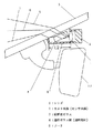
図6は従来の車窓内センサである車窓内カメラの断面図である。
この車窓内カメラは、窓ガラスである前面窓ガラス3の内側に設けられたレンズ1と、前面窓ガラス3の外側の被検出体(図示せず)をレンズ1を通じて検出するセンサ本体であるカメラ本体2とを備えている。
この車窓内カメラは、被検出体からの上側入射光線5、中央入射光線6および下側入射光線7が前面窓ガラス3を通じてレンズ1に入射し、カメラ本体2で被検出体を撮像している。
【0003】
【発明が解決しようとする課題】
しかしながら、この車窓内カメラは、前面窓ガラス3からレンズ1に直接入光し、前面窓ガラス3からレンズ1に入光する最大光路距離L1(下側入射光線7が前面窓ガラス3の内側面を出た点とレンズ1の中心線との間の水平距離)が長くなってしまうという問題点があった。
【0004】
また、このとき、ダッシュボード等に反射した写りこみ光線11が前面窓ガラス3で反射し、上側入射光線5、中央入射光線6および下側入射光線7と同じ光路でレンズ1に入射し、ダッシュボード等の画像が被検出体の画像と重なり、撮像画像の品質が劣化するという問題点もあった。
この問題点を解決する手段として、例えば特開平4−194827号公報に開示されているように、カメラ本体4と前面窓ガラス3との間を図7に示すフード9で覆ってダッシュボード等に反射した写りこみ光線11を遮光する手段が採用されている。
しかしながら、近年、空気抵抗の低減を目的として前面窓ガラス3の傾斜角度が大きくなる傾向にあり、それに伴って前記光路距離L1も長くなってフード9も大きくならざるを得ず、そのことが乗員の視界を妨げてしまい、またルームミラー12に干渉されないようにするために車窓内カメラを適所に取り付けることができないという問題点があった。
【0005】
この発明は、上記のような問題点を解決することを課題とするものであって、窓ガラスからレンズに入光する前記最大光路距離を短縮して小型化することができる等の車窓内センサを得ることを目的とする。
【0006】
【課題を解決するための手段】
この発明の車窓内センサは、傾斜した窓ガラスの内側に設けられ窓ガラスの外側の被検出体からの光を集めるレンズと、このレンズを通った前記光を通じて前記被検出体を検出するセンサ本体と、前記窓ガラスと前記レンズとの間に設けられ窓ガラスを通過した前記被検出体からの光を屈折する透明部材とを備え、前記透明部材は前記窓ガラスと平行に配置されたものである。
【0007】
また、この発明に係る車窓内センサでは、窓ガラスとレンズとの間を被検出体以外からの不要光線を遮光するフードで覆っている。
【0009】
また、この発明に係る車窓内センサでは、窓ガラスとレンズとの間に被検出体以外からの不要光線を遮光する遮光部材を介在したものである。
【0010】
また、この発明に係る車窓内センサでは、透明部材を窓ガラスに光透過性接着剤で接着したものである。
【0011】
また、この発明に係る車窓内センサでは、透明部材に被検出体以外からの不要光線を遮光又は吸収する光遮光・吸収手段を設けたものである。
【0012】
また、この発明に係る車窓内センサでは、光遮光・吸収手段は墨である。
【0013】
また、この発明に係る車窓内センサでは、フードには通気性防塵フィルタが設けられている。
【0014】
また、この発明に係る車窓内センサでは、透明部材は透明ガラス板である。
【0015】
また、この発明に係る車窓内センサでは、センサ本体はカメラ本体である。
【0016】
【発明の実施の形態】
以下、この発明の車窓内センサである車窓内カメラについて説明するが、従来のものと同一、または相当部材、部位については、同一符号を付して説明する。
実施の形態1.
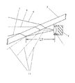
図1は実施の形態1の車窓内カメラの側断面図であり、この車窓内カメラは、傾斜した窓ガラスである前面窓ガラス3の内側に設けられたレンズ1と、前面窓ガラス3の外側の被検出体(図示せず)をレンズ1を通じて検出するセンサ本体であるカメラ本体2と、前面窓ガラス3とレンズ1との間に設けられ前面窓ガラス3を通過した被検出体からの光を屈折する透明部材である透明ガラス板4と、前面窓ガラス3とレンズ1との間を覆っているフード9とを備えている。透明ガラス板4は前面窓ガラス3と平行に配置されている。
この車窓内カメラは、被検出体からの上側入射光線5、中央入射光線6および下側入射光線7が前面窓ガラス3、透明ガラス板4を通じてレンズ1に入射し、カメラ本体2で被検出体を撮像している。
【0017】
このものの場合、上側入射光線5、中央入射光線6および下側入射光線7が前面窓ガラス3、透明ガラス板4を通じてレンズ1に入射するが、その光路途中、透明ガラス板4の屈折率が空気より大きいので、従来のものと比較して下側にシフトする。従って、前面窓ガラス3に対するカメラ本体2の取り付け位置が従来のものと同一であるときには、従来のものと比較してレンズ1に入光する上側入射光線5、中央入射光線6および下側入射光線7は上側にシフトし、前面窓ガラス3からレンズ1に入光する最大光路距離L2(下側入射光線7が前面窓ガラス3の内側面を出た点とレンズ1の中心線との間の水平距離)は短縮される。従って、カメラ本体4と前面窓ガラス3との間を覆ってダッシュボード等に反射した写りこみ光線11を遮光するフード9の長さを短くすることができる。
なお、このフード9は、車室内空気中に浮遊する塵埃、煙草の煙によるレンズ1の汚染を防止している。
また、透明ガラス板4は前面窓ガラス3と平行に配置されている、即ち前面窓ガラス3に沿ったスペースに透明ガラス板4は配置されており、フード9を大きくすることなく、透明ガラス板4を配置することができる。
【0018】
実施の形態2.
図2は実施の形態2の車窓内カメラの側断面図であり、フード9に通気性防塵フィルタ20が設けられている点が実施の形態1と異なる。
【0019】
上記構成の車窓内カメラでは、フード9には通気性防塵フィルタ20が着脱可能に取り付けられているので、フード9の内外との間で空気が移動でき、フード9の内外の温度、湿度条件を同程度に保つことができる。
従って、車室内で結露が生じる条件下ではフード9内のレンズ1は前面窓ガラス3と同様に表面に結露が生じてしまうが、フード9の内外気温の変化によりフード9内のレンズ1の表面および前面窓ガラス3の内面のみに結露が生じるようなことはない。なお、レンズ1の表面に生じた結露を早急に除去する必要性が生じたときには、通気性防塵フィルタ20を取り外して人手により布等で拭き取ればよい。
また、煙草の煙の微粒子等を含んだ車室内の空気がフード9内に流入しようとするときに、微粒子等は通気性防塵フィルタ9で捕集されるので、フード9内のレンズ1の表面および前面窓ガラス3の内面が汚染されるようなことはない。
【0020】
従って、車窓内カメラは、フード9内のレンズ1の表面および前面窓ガラス3の一部(フード9で囲まれた窓ガラス3の部分)のみに結露が生じるようなことはなく、またフード9内のレンズ1の表面および前面窓ガラス3の一部が車室内の汚れの影響を受けるようなことはなく、被検出体である被撮像体を撮像することができる。
【0021】
実施の形態3.
図3は実施の形態3の車窓内カメラの側断面図であり、透明ガラス板4を前面窓ガラス3に光透過性接着剤21で接着した点が実施の形態1と異なる。
この実施の形態では、前面窓ガラス3と透明ガラス板4との間に空気層が介在していないので、透明ガラス板4に入射する光は反射することなく透明ガラス板4に入射し、また透明ガラス板4の前面窓ガラス3側では、塵埃、水滴等が付着することがなく、良質な画像を得ることができる。
【0022】
実施の形態4.
図4は実施の形態4の車窓内カメラの側断面図であり、前面窓ガラス3とレンズ1との間に被検出体以外の不要光線を遮光する遮光部材8を介在させた点が実施の形態1と異なる。
この実施の形態では、例えば太陽光線の直射等の不要光線である不要入射光線25は遮光部材8で遮光され、ゴースト、へレアの無い良質な画像を得ることができる。
【0023】
実施の形態5.
図5は実施の形態5の車窓内カメラの側断面図であり、透明ガラス板4および前面窓ガラス3の一部に不要光線を遮光又は吸収する光遮光・吸収手段を施した点、および透明ガラス板4とレンズ1との間にフード9を設けた点が実施の形態3と異なる。光遮光・吸収手段は、砂摺り面処理を施した後、墨10を塗布して構成されている。
この実施の形態では、例えば太陽光線の直射等の不要の光線である不要入射光線25は墨10で遮光され、ゴースト、へレアの無い良質な画像を得ることができる。
【0024】
なお、上記各実施の形態では、前面窓ガラスの前方の被検出体を検出する車窓内センサについて説明したが、例えば後面窓ガラスの後方の被検出体を検出する車窓内センサであってもよい。
また、上記各実施の形態では、センサ本体として、カメラ本体について説明したが、勿論このものに限定されるものではなく、センサとして例えばレーザーレーダーを用い、レーザーレーダー本体で撮像された画像を電気的に処理することにより、車外の被検出体である対象物までの距離、あるいは被検出体である障害物の有無を検出するようにしてもよい。
【0025】
【発明の効果】
以上説明したように、この発明に係る車窓内センサによれば、傾斜した窓ガラスの内側に設けられ窓ガラスの外側の被検出体からの光を集めるレンズと、このレンズを通った前記光を通じて前記被検出体を検出するセンサ本体と、前記窓ガラスと前記レンズとの間に設けられ窓ガラスを通過した前記被検出体からの光を屈折する透明部材とを備えたので、被検出体からの光が窓ガラスの内側面を出た点とレンズの中心線との間の水平距離を短縮することが可能となり、車窓内センサを小型化することができる。
また、この発明に係る車窓内センサによれば、透明部材を窓ガラスと平行に配置したので、例えば例えば窓ガラスとレンズとの間を覆った不要光線を遮光するフードを大きくすることなく透明部材を配置することができる。
【0026】
また、この発明に係る車窓内センサによれば、窓ガラスとレンズとの間をフードで覆っているので、例えばダッシュボード等に反射した写りこみ光線が窓ガラス、透明部材に入射するのを防止することができる。
【0028】
また、この発明に係る車窓内センサによれば、窓ガラスとレンズとの間に被検出体以外からの不要光線を遮光する遮光部材を介在したので、例えば太陽光線の直射等の不要光線が遮光部材で遮光され、ゴースト、へレアの無い良質な画像を得ることができる。
【0029】
また、この発明に係る車窓内センサによれば、透明部材を窓ガラスに光透過性接着剤で接着したので、窓ガラスと透明部材との間に空気層が介在せず、透明部材に入射する光は反射することなく透明部材に入射し、また透明部材の窓ガラス側では、塵埃、水滴等が付着するようなことはなく、良質な画像を得ることができる。
【0030】
また、この発明に係る車窓内センサによれば、透明部材に被検出体以外からの不要光線を遮光又は吸収する光遮光・吸収手段を設けたので、例えば太陽光線の直射等の不要光線が光遮光・吸収手段で遮光、吸収され、ゴースト、へレアの無い良質な画像を得ることができる。
【0031】
また、この発明に係る車窓内センサによれば、光遮光・吸収手段は墨であるので、安価、簡単に不要光線が遮光、吸収され、ゴースト、へレアの無い良質な画像を得ることができる。
【0032】
また、この発明に係る車窓内センサによれば、フードには通気性防塵フィルタが設けられているので、車窓内センサは、フード内のレンズの表面、およびフードで囲まれた窓ガラスの一部のみに結露が生じるようなことはない。また、フード内のレンズの表面および窓ガラスの一部が車室内の汚れの影響を受けることなく、被検出体を撮像することができる。
【0033】
また、この発明に係る車窓内センサによれば、透明部材は透明ガラス板であるので、安価に透明部材を得ることができる。
【0034】
また、この発明に係る車窓内センサによれば、センサ本体はカメラ本体であるので、車窓外の被撮像体を撮像することができる。
【図面の簡単な説明】
【図1】この発明の実施の形態1の車室内カメラの側断面図である。
【図2】この発明の実施の形態2の車室内カメラの側断面図である。
【図3】この発明の実施の形態3の車室内カメラの側断面図である。
【図4】この発明の実施の形態4の車室内カメラの側断面図である。
【図5】この発明の実施の形態5の車室内カメラの側断面図である。
【図6】従来の車室内カメラの側断面図である。
【図7】従来の車室内カメラの他の例を示す側断面図である。
【符号の説明】
1 レンズ、2 カメラ本体(センサ本体)、3 前面窓ガラス、4 透明ガラス板(透明部材)、9 フード、10 墨(光遮光・吸収手段)、20 通気性防塵フィルタ。[0001]
TECHNICAL FIELD OF THE INVENTION
The present invention relates to an in-vehicle sensor installed in a vehicle window to detect an object to be detected outside the vehicle.
[0002]
[Prior art]
FIG. 6 is a cross-sectional view of a vehicle interior camera which is a conventional vehicle interior sensor.
The camera in a vehicle window is a camera that is a sensor body that detects a
In the camera in the vehicle window, the upper
[0003]
[Problems to be solved by the invention]
However, the camera in the car window directly enters the
[0004]
At this time, the reflected light beam 11 reflected on the dashboard or the like is reflected by the
As means for solving this problem, for example, as disclosed in Japanese Patent Application Laid-Open No. H4-194827, the space between the
However, in recent years, the inclination angle of the
[0005]
An object of the present invention is to solve the above-described problems, and to reduce the size of the vehicle window sensor by shortening the maximum optical path distance of light entering a lens from a window glass. The purpose is to obtain.
[0006]
[Means for Solving the Problems]
A sensor in a vehicle window according to the present invention includes a lens provided inside an inclined windowpane for collecting light from an object outside the windowpane, and a sensor body for detecting the object through the light passing through the lens. And a transparent member provided between the window glass and the lens and refracting light from the object to be detected that has passed through the window glass , wherein the transparent member is disposed in parallel with the window glass. is there.
[0007]
In the vehicle window sensor according to the present invention, the space between the window glass and the lens is covered with a hood that blocks unnecessary light rays other than those to be detected.
[0009]
Also, in the car window in the sensor according to this invention is obtained by interposing a light shielding member for shielding unnecessary light from other than the object to be detected between the window glass and the lens.
[0010]
Further, in the vehicle interior sensor according to the present invention, the transparent member is bonded to the window glass with a light transmitting adhesive.
[0011]
In the vehicle window sensor according to the present invention, the transparent member is provided with a light blocking / absorbing means for blocking or absorbing unnecessary light rays other than those to be detected.
[0012]
In the vehicle window sensor according to the present invention, the light shielding / absorbing means is black.
[0013]
In the vehicle window sensor according to the present invention, the hood is provided with the air-permeable dustproof filter.
[0014]
In the vehicle window sensor according to the present invention, the transparent member is a transparent glass plate.
[0015]
In the vehicle window sensor according to the present invention, the sensor body is a camera body.
[0016]
BEST MODE FOR CARRYING OUT THE INVENTION
Hereinafter, a vehicle window camera which is a vehicle window sensor according to the present invention will be described, but the same reference numerals will be given to the same or equivalent members and portions as those of the conventional camera.
FIG. 1 is a side sectional view of a camera in a vehicle window according to the first embodiment. The camera in a vehicle window includes a
In this camera in a vehicle window, an upper
[0017]
In this case, the upper
The
Further, the
[0018]
FIG. 2 is a side sectional view of the camera in the vehicle window according to the second embodiment, which is different from the first embodiment in that a
[0019]
In the camera in the vehicle window having the above configuration, the air-
Therefore, under the condition that dew condensation occurs in the vehicle interior, dew condensation occurs on the surface of the
Further, when air in the vehicle compartment containing fine particles of tobacco smoke and the like attempts to flow into the
[0020]
Therefore, the camera in the car window does not cause condensation on only the surface of the
[0021]
FIG. 3 is a side sectional view of a camera in a vehicle window according to the third embodiment, which is different from the first embodiment in that a
In this embodiment, since no air layer is interposed between the
[0022]
FIG. 4 is a side sectional view of the camera in the vehicle window according to the fourth embodiment. The embodiment is different from the
In this embodiment, for example, unnecessary incident light rays 25, which are unnecessary light rays such as direct rays of sunlight, are shielded by the
[0023]
FIG. 5 is a side sectional view of a camera in a vehicle window according to the fifth embodiment. The
In this embodiment, unnecessary incident light rays 25, which are unnecessary light rays such as direct sunlight rays, are shielded by the
[0024]
In each of the above embodiments, the in-vehicle sensor for detecting the object to be detected in front of the front window glass has been described. However, for example, the in-vehicle sensor for detecting the to-be-detected object behind the rear window glass may be used. .
Further, in each of the above-described embodiments, the camera body has been described as the sensor body. However, the sensor body is not limited to the camera body. For example, a laser radar is used as the sensor, and an image captured by the laser radar body is electrically connected. , The distance to the target object outside the vehicle or the presence or absence of the obstacle as the detected object may be detected.
[0025]
【The invention's effect】
As described above, according to the in-car window sensor according to the present invention, the lens provided inside the inclined window glass to collect light from the object to be detected outside the window glass, and the light passing through the lens, Since the sensor body that detects the object to be detected, and a transparent member provided between the window glass and the lens and refracting light from the object to be detected that has passed through the window glass, The horizontal distance between the point at which the light exits the inner side surface of the window glass and the center line of the lens can be reduced, and the size of the sensor in the vehicle window can be reduced.
Further, according to the sensor in the vehicle window according to the present invention, since the transparent member is disposed in parallel with the window glass, for example, the transparent member can be provided without increasing the size of a hood that blocks unnecessary light rays covering between the window glass and the lens. Can be arranged.
[0026]
Further, according to the sensor in the vehicle window according to the present invention, since the hood covers the window glass and the lens, it prevents, for example, reflected light reflected on the dashboard or the like from entering the window glass or the transparent member. can do.
[0028]
Further, according to the sensor in the vehicle window according to the present invention, since the light shielding member for shielding unnecessary light from other than the object to be detected is interposed between the window glass and the lens, unnecessary light such as direct rays of sunlight is blocked. Good quality images free from ghosts and blemishes can be obtained, being shielded from light by the member.
[0029]
According to the sensor in the vehicle window according to the present invention, since the transparent member is bonded to the window glass with the light transmitting adhesive, no air layer is interposed between the window glass and the transparent member, and the light enters the transparent member. Light is incident on the transparent member without reflection, and dust and water droplets do not adhere to the window glass side of the transparent member, and a high-quality image can be obtained.
[0030]
Further, according to the sensor in the vehicle window according to the present invention, since the transparent member is provided with the light shielding / absorbing means for shielding or absorbing unnecessary light from the object other than the object to be detected, unnecessary light such as direct rays of sunlight is emitted. High quality images free from ghosts and blemishes can be obtained, which are shaded and absorbed by the shading / absorbing means.
[0031]
Further, according to the sensor in the vehicle window according to the present invention, since the light shielding / absorbing means is black, unnecessary light can be easily shielded and absorbed at low cost, and a high-quality image free from ghosts and blemishes can be obtained. .
[0032]
Moreover, according to the sensor in the vehicle window according to the present invention, since the hood is provided with the air-permeable dustproof filter, the sensor in the vehicle window includes the surface of the lens in the hood and a part of the window glass surrounded by the hood. There is no possibility that condensation will occur only in the case. Moreover, the surface of the lens in the hood and a part of the window glass can be imaged on the detection target without being affected by dirt in the vehicle interior.
[0033]
Further, according to the in-car window sensor according to the present invention, since the transparent member is a transparent glass plate, the transparent member can be obtained at low cost.
[0034]
Further, according to the sensor in the vehicle window according to the present invention, since the sensor main body is the camera main body, it is possible to image an object to be imaged outside the vehicle window.
[Brief description of the drawings]
FIG. 1 is a side sectional view of a vehicle interior camera according to
FIG. 2 is a side sectional view of a vehicle interior camera according to
FIG. 3 is a side sectional view of a vehicle interior camera according to
FIG. 4 is a side sectional view of a vehicle interior camera according to
FIG. 5 is a side sectional view of a vehicle interior camera according to
FIG. 6 is a side sectional view of a conventional vehicle interior camera.
FIG. 7 is a side sectional view showing another example of a conventional vehicle interior camera.
[Explanation of symbols]
1 lens, 2 camera body (sensor body), 3 front window glass, 4 transparent glass plate (transparent member), 9 hood, 10 ink (light shielding / absorbing means), 20 breathable dustproof filter.
Claims (9)
Priority Applications (3)
| Application Number | Priority Date | Filing Date | Title |
|---|---|---|---|
| JP2001213348A JP3565802B2 (en) | 2001-07-13 | 2001-07-13 | Vehicle window sensor |
| US10/002,200 US6768092B2 (en) | 2001-07-13 | 2001-12-05 | Sensor in car window |
| DE10160669A DE10160669C5 (en) | 2001-07-13 | 2001-12-11 | Sensor in a vehicle window |
Applications Claiming Priority (1)
| Application Number | Priority Date | Filing Date | Title |
|---|---|---|---|
| JP2001213348A JP3565802B2 (en) | 2001-07-13 | 2001-07-13 | Vehicle window sensor |
Publications (2)
| Publication Number | Publication Date |
|---|---|
| JP2003025928A JP2003025928A (en) | 2003-01-29 |
| JP3565802B2 true JP3565802B2 (en) | 2004-09-15 |
Family
ID=19048341
Family Applications (1)
| Application Number | Title | Priority Date | Filing Date |
|---|---|---|---|
| JP2001213348A Expired - Fee Related JP3565802B2 (en) | 2001-07-13 | 2001-07-13 | Vehicle window sensor |
Country Status (3)
| Country | Link |
|---|---|
| US (1) | US6768092B2 (en) |
| JP (1) | JP3565802B2 (en) |
| DE (1) | DE10160669C5 (en) |
Families Citing this family (38)
| Publication number | Priority date | Publication date | Assignee | Title |
|---|---|---|---|---|
| US6326613B1 (en) | 1998-01-07 | 2001-12-04 | Donnelly Corporation | Vehicle interior mirror assembly adapted for containing a rain sensor |
| US6124886A (en) | 1997-08-25 | 2000-09-26 | Donnelly Corporation | Modular rearview mirror assembly |
| US6278377B1 (en) | 1999-08-25 | 2001-08-21 | Donnelly Corporation | Indicator for vehicle accessory |
| US8288711B2 (en) | 1998-01-07 | 2012-10-16 | Donnelly Corporation | Interior rearview mirror system with forwardly-viewing camera and a control |
| US6690268B2 (en) | 2000-03-02 | 2004-02-10 | Donnelly Corporation | Video mirror systems incorporating an accessory module |
| US6445287B1 (en) | 2000-02-28 | 2002-09-03 | Donnelly Corporation | Tire inflation assistance monitoring system |
| US6420975B1 (en) | 1999-08-25 | 2002-07-16 | Donnelly Corporation | Interior rearview mirror sound processing system |
| US7480149B2 (en) | 2004-08-18 | 2009-01-20 | Donnelly Corporation | Accessory module for vehicle |
| US6396408B2 (en) | 2000-03-31 | 2002-05-28 | Donnelly Corporation | Digital electrochromic circuit with a vehicle network |
| US6824281B2 (en) | 2002-01-31 | 2004-11-30 | Donnelly Corporation | Vehicle accessory module |
| DE10319176A1 (en) * | 2003-04-29 | 2004-11-18 | Robert Bosch Gmbh | Device for cooling a camera |
| DE10329900A1 (en) * | 2003-07-03 | 2005-02-17 | Daimlerchrysler Ag | Camera system for a motor vehicle |
| WO2006063827A1 (en) | 2004-12-15 | 2006-06-22 | Magna Donnelly Electronics Naas Limited | An accessory module system for a vehicle window |
| DE102006005168A1 (en) | 2006-02-06 | 2007-08-09 | Leopold Kostal Gmbh & Co. Kg | camera assembly |
| DE102006059555B4 (en) * | 2006-12-16 | 2016-08-04 | Leopold Kostal Gmbh & Co. Kg | camera assembly |
| DE102007037091A1 (en) | 2007-08-06 | 2009-02-12 | Daimler Ag | Night vision system for motor vehicles |
| EP2247468B1 (en) * | 2008-03-03 | 2013-03-20 | Daimler AG | Stray light and sun shield for a camera in a motor vehicle |
| US8570374B2 (en) | 2008-11-13 | 2013-10-29 | Magna Electronics Inc. | Camera for vehicle |
| EP2206601A1 (en) | 2009-01-08 | 2010-07-14 | Saint Gobain Glass France | Plate with a function element |
| DE202009018111U1 (en) | 2009-01-15 | 2011-01-13 | Saint-Gobain Sekurit Deutschland Gmbh & Co. Kg | Slice with a daylight absorbing disc segment |
| DE102009061059A1 (en) * | 2009-04-23 | 2011-06-09 | Saint-Gobain Sekurit Deutschland Gmbh & Co. Kg | vehicle glazing |
| DE102009019381A1 (en) * | 2009-04-29 | 2010-11-04 | Valeo Schalter Und Sensoren Gmbh | Holder for a light-sensitive sensor behind a transparent pane |
| DE102009027520A1 (en) * | 2009-07-08 | 2011-01-20 | Robert Bosch Gmbh | Distortion correction of video systems |
| EP2390141B1 (en) | 2010-05-31 | 2014-09-24 | Volvo Car Corporation | Optical sensor interface |
| JP5316562B2 (en) | 2011-02-10 | 2013-10-16 | 株式会社デンソー | Car camera |
| US8897633B2 (en) | 2010-12-21 | 2014-11-25 | Denso Corporation | In-vehicle camera unit having camera built into body |
| US10046716B2 (en) | 2011-02-10 | 2018-08-14 | Denso Corporation | In-vehicle camera and vehicle control system |
| US20150042874A1 (en) * | 2013-08-08 | 2015-02-12 | Nidec Elesys Corporation | In-vehicle camera |
| DE102014220765A1 (en) | 2014-10-14 | 2016-04-14 | Robert Bosch Gmbh | Device for a motor vehicle comprising an optical surface sensor with an optical half-axis and an optic with an opening angle and use of the device in a vehicle |
| JP2016168996A (en) * | 2015-03-12 | 2016-09-23 | 日本板硝子株式会社 | Windshield |
| WO2016143582A1 (en) * | 2015-03-12 | 2016-09-15 | 日本板硝子株式会社 | Windshield |
| CN112326557A (en) | 2015-03-24 | 2021-02-05 | 伊鲁米那股份有限公司 | Method, carrier assembly and system for imaging a sample for biological or chemical analysis |
| JP6904338B2 (en) * | 2016-04-27 | 2021-07-14 | Agc株式会社 | Window members and vehicle window glass |
| CN111781139B (en) | 2016-10-14 | 2023-09-12 | 亿明达股份有限公司 | Clamping box assembly |
| JP6805854B2 (en) * | 2017-02-02 | 2020-12-23 | 株式会社Jvcケンウッド | In-vehicle shooting device and reflection suppression method |
| CN108528354B (en) * | 2018-06-04 | 2023-08-08 | 威马智慧出行科技(上海)有限公司 | Vehicle-mounted camera bracket and automobile comprising same |
| JP7216325B2 (en) * | 2019-02-13 | 2023-02-01 | Agc株式会社 | Vehicle window glass with optical device |
| AU2022214367A1 (en) * | 2021-01-29 | 2023-08-17 | AGC Inc. | Imaging device |
Family Cites Families (8)
| Publication number | Priority date | Publication date | Assignee | Title |
|---|---|---|---|---|
| US1637309A (en) * | 1927-07-26 | Signal-viewing attachment for automobiles | ||
| US1080208A (en) * | 1912-10-28 | 1913-12-02 | George W Gardner | Cleaner for engine-cylinders. |
| US2109932A (en) * | 1936-06-05 | 1938-03-01 | Harvey C Schneider | Image forming device for automobiles |
| US4286846A (en) * | 1977-03-07 | 1981-09-01 | Bollenbacher Dale E | Signal viewer for automobile |
| JPH04194827A (en) | 1990-11-22 | 1992-07-14 | Mitsubishi Electric Corp | On-vehicle image pickup device |
| DE19704415A1 (en) * | 1997-02-06 | 1998-08-13 | Hella Kg Hueck & Co | Sensor device for automatic driving light switching |
| DE19805000A1 (en) * | 1998-02-07 | 1999-08-12 | Opel Adam Ag | Optical sensor device for motor vehicles |
| US6657176B2 (en) * | 2000-04-12 | 2003-12-02 | Autonetworks Technologies, Ltd. | On-vehicle image pick-up apparatus and method of setting image pick-up direction |
-
2001
- 2001-07-13 JP JP2001213348A patent/JP3565802B2/en not_active Expired - Fee Related
- 2001-12-05 US US10/002,200 patent/US6768092B2/en not_active Expired - Fee Related
- 2001-12-11 DE DE10160669A patent/DE10160669C5/en not_active Expired - Fee Related
Also Published As
| Publication number | Publication date |
|---|---|
| US6768092B2 (en) | 2004-07-27 |
| DE10160669B4 (en) | 2005-05-25 |
| US20030010890A1 (en) | 2003-01-16 |
| JP2003025928A (en) | 2003-01-29 |
| DE10160669A1 (en) | 2003-05-08 |
| DE10160669C5 (en) | 2012-06-14 |
Similar Documents
| Publication | Publication Date | Title |
|---|---|---|
| JP3565802B2 (en) | Vehicle window sensor | |
| EP1025702B1 (en) | Rain sensor with fog discrimination | |
| US6313454B1 (en) | Rain sensor | |
| JP4278879B2 (en) | Vehicle periphery visual recognition device | |
| JP4359121B2 (en) | Multifunction integrated vision system with a matrix of CMOS or CCD technology | |
| JPH03266739A (en) | Car-loaded image pickup device | |
| JP2002539421A (en) | Device for detecting objects present on the windshield of a car | |
| US20230030157A1 (en) | Speckle detection systems, image capturing devices and methods | |
| US20160144797A1 (en) | Camera assembly for a vehicle, and vehicle having such a camera assembly | |
| JP6785552B2 (en) | Imaging device | |
| JP2004025930A (en) | Camera cover of on-vehicle camera | |
| KR20210022075A (en) | Laminated vehicle panes with opaque polymer film | |
| CN112533795B (en) | Holding device for holding a sensor unit and arrangement of holding devices | |
| JP2013255064A (en) | Reflection reductive on-vehicle camera system | |
| JP6575472B2 (en) | In-vehicle optical sensor device | |
| JP6815957B2 (en) | door mirror | |
| JP2021187369A (en) | On-vehicle camera device | |
| JP2016218044A (en) | Window surface detection sensor | |
| JP3792478B2 (en) | Vehicle periphery visual recognition device | |
| JP2008260430A (en) | Solar radiation sensor fitting structure | |
| JP3706007B2 (en) | Vehicle periphery visual recognition device | |
| CN218336224U (en) | Camera cleaning device and camera module | |
| WO2016185980A1 (en) | Window surface detection sensor | |
| JPH099114A (en) | On-vehicle camera and method for preventing ghost of the on-vehicle camera | |
| JP6943177B2 (en) | External information acquisition device |
Legal Events
| Date | Code | Title | Description |
|---|---|---|---|
| TRDD | Decision of grant or rejection written | ||
| A01 | Written decision to grant a patent or to grant a registration (utility model) |
Free format text: JAPANESE INTERMEDIATE CODE: A01 Effective date: 20040601 |
|
| A61 | First payment of annual fees (during grant procedure) |
Free format text: JAPANESE INTERMEDIATE CODE: A61 Effective date: 20040608 |
|
| R150 | Certificate of patent or registration of utility model |
Free format text: JAPANESE INTERMEDIATE CODE: R150 |
|
| FPAY | Renewal fee payment (event date is renewal date of database) |
Free format text: PAYMENT UNTIL: 20080618 Year of fee payment: 4 |
|
| FPAY | Renewal fee payment (event date is renewal date of database) |
Free format text: PAYMENT UNTIL: 20080618 Year of fee payment: 4 |
|
| FPAY | Renewal fee payment (event date is renewal date of database) |
Free format text: PAYMENT UNTIL: 20090618 Year of fee payment: 5 |
|
| FPAY | Renewal fee payment (event date is renewal date of database) |
Free format text: PAYMENT UNTIL: 20100618 Year of fee payment: 6 |
|
| FPAY | Renewal fee payment (event date is renewal date of database) |
Free format text: PAYMENT UNTIL: 20100618 Year of fee payment: 6 |
|
| FPAY | Renewal fee payment (event date is renewal date of database) |
Free format text: PAYMENT UNTIL: 20110618 Year of fee payment: 7 |
|
| FPAY | Renewal fee payment (event date is renewal date of database) |
Free format text: PAYMENT UNTIL: 20120618 Year of fee payment: 8 |
|
| FPAY | Renewal fee payment (event date is renewal date of database) |
Free format text: PAYMENT UNTIL: 20130618 Year of fee payment: 9 |
|
| LAPS | Cancellation because of no payment of annual fees |