JP2007248362A - Terminal positioning system and position measuring method - Google Patents
Terminal positioning system and position measuring method Download PDFInfo
- Publication number
- JP2007248362A JP2007248362A JP2006074616A JP2006074616A JP2007248362A JP 2007248362 A JP2007248362 A JP 2007248362A JP 2006074616 A JP2006074616 A JP 2006074616A JP 2006074616 A JP2006074616 A JP 2006074616A JP 2007248362 A JP2007248362 A JP 2007248362A
- Authority
- JP
- Japan
- Prior art keywords
- base station
- terminal
- positioning
- signal
- propagation time
- Prior art date
- Legal status (The legal status is an assumption and is not a legal conclusion. Google has not performed a legal analysis and makes no representation as to the accuracy of the status listed.)
- Ceased
Links
Images


Classifications
-
- G—PHYSICS
- G01—MEASURING; TESTING
- G01S—RADIO DIRECTION-FINDING; RADIO NAVIGATION; DETERMINING DISTANCE OR VELOCITY BY USE OF RADIO WAVES; LOCATING OR PRESENCE-DETECTING BY USE OF THE REFLECTION OR RERADIATION OF RADIO WAVES; ANALOGOUS ARRANGEMENTS USING OTHER WAVES
- G01S5/00—Position-fixing by co-ordinating two or more direction or position line determinations; Position-fixing by co-ordinating two or more distance determinations
- G01S5/02—Position-fixing by co-ordinating two or more direction or position line determinations; Position-fixing by co-ordinating two or more distance determinations using radio waves
- G01S5/0284—Relative positioning
- G01S5/0289—Relative positioning of multiple transceivers, e.g. in ad hoc networks
-
- G—PHYSICS
- G01—MEASURING; TESTING
- G01S—RADIO DIRECTION-FINDING; RADIO NAVIGATION; DETERMINING DISTANCE OR VELOCITY BY USE OF RADIO WAVES; LOCATING OR PRESENCE-DETECTING BY USE OF THE REFLECTION OR RERADIATION OF RADIO WAVES; ANALOGOUS ARRANGEMENTS USING OTHER WAVES
- G01S5/00—Position-fixing by co-ordinating two or more direction or position line determinations; Position-fixing by co-ordinating two or more distance determinations
- G01S5/02—Position-fixing by co-ordinating two or more direction or position line determinations; Position-fixing by co-ordinating two or more distance determinations using radio waves
- G01S5/0205—Details
- G01S5/0221—Receivers
- G01S5/02213—Receivers arranged in a network for determining the position of a transmitter
- G01S5/02216—Timing or synchronisation of the receivers
-
- G—PHYSICS
- G01—MEASURING; TESTING
- G01S—RADIO DIRECTION-FINDING; RADIO NAVIGATION; DETERMINING DISTANCE OR VELOCITY BY USE OF RADIO WAVES; LOCATING OR PRESENCE-DETECTING BY USE OF THE REFLECTION OR RERADIATION OF RADIO WAVES; ANALOGOUS ARRANGEMENTS USING OTHER WAVES
- G01S5/00—Position-fixing by co-ordinating two or more direction or position line determinations; Position-fixing by co-ordinating two or more distance determinations
- G01S5/02—Position-fixing by co-ordinating two or more direction or position line determinations; Position-fixing by co-ordinating two or more distance determinations using radio waves
- G01S5/0205—Details
- G01S5/0226—Transmitters
-
- G—PHYSICS
- G01—MEASURING; TESTING
- G01S—RADIO DIRECTION-FINDING; RADIO NAVIGATION; DETERMINING DISTANCE OR VELOCITY BY USE OF RADIO WAVES; LOCATING OR PRESENCE-DETECTING BY USE OF THE REFLECTION OR RERADIATION OF RADIO WAVES; ANALOGOUS ARRANGEMENTS USING OTHER WAVES
- G01S5/00—Position-fixing by co-ordinating two or more direction or position line determinations; Position-fixing by co-ordinating two or more distance determinations
- G01S5/02—Position-fixing by co-ordinating two or more direction or position line determinations; Position-fixing by co-ordinating two or more distance determinations using radio waves
- G01S5/0205—Details
- G01S5/0244—Accuracy or reliability of position solution or of measurements contributing thereto
-
- G—PHYSICS
- G01—MEASURING; TESTING
- G01S—RADIO DIRECTION-FINDING; RADIO NAVIGATION; DETERMINING DISTANCE OR VELOCITY BY USE OF RADIO WAVES; LOCATING OR PRESENCE-DETECTING BY USE OF THE REFLECTION OR RERADIATION OF RADIO WAVES; ANALOGOUS ARRANGEMENTS USING OTHER WAVES
- G01S5/00—Position-fixing by co-ordinating two or more direction or position line determinations; Position-fixing by co-ordinating two or more distance determinations
- G01S5/02—Position-fixing by co-ordinating two or more direction or position line determinations; Position-fixing by co-ordinating two or more distance determinations using radio waves
- G01S5/14—Determining absolute distances from a plurality of spaced points of known location
-
- H—ELECTRICITY
- H04—ELECTRIC COMMUNICATION TECHNIQUE
- H04W—WIRELESS COMMUNICATION NETWORKS
- H04W64/00—Locating users or terminals or network equipment for network management purposes, e.g. mobility management
-
- H—ELECTRICITY
- H04—ELECTRIC COMMUNICATION TECHNIQUE
- H04W—WIRELESS COMMUNICATION NETWORKS
- H04W88/00—Devices specially adapted for wireless communication networks, e.g. terminals, base stations or access point devices
- H04W88/08—Access point devices
Abstract
Description
本発明は、無線通信端末の位置を測定する端末測位システムに関し、特に、位置測定のために用いられる基地局の位置を確定する技術に関する。 The present invention relates to a terminal positioning system that measures the position of a wireless communication terminal, and more particularly to a technique for determining the position of a base station used for position measurement.
移動端末の位置を測定するシステムとして、端末から送信される信号を複数の基地局で受信した時間差を計算し、受信時間差に光速を乗算することによって、ノードからの各基地局までの信号の伝搬距離を算出し、ノードの位置を検出するシステムが提案されている(例えば、非特許文献1参照。)。 As a system for measuring the position of a mobile terminal, propagation of signals from a node to each base station is calculated by calculating the time difference when signals transmitted from the terminal are received by multiple base stations and multiplying the reception time difference by the speed of light. A system for calculating a distance and detecting the position of a node has been proposed (see, for example, Non-Patent Document 1).
例えば、特許文献1には、複数の基地局を備えた端末測位システムが開示されている。この端末測位システムは、位置計算サーバ、アクセスポイント(基地局)、基準局及びノード(端末)を備える。各基地局と位置計算サーバは、有線のネットワークによって接続される。
For example,
ノードは、無線送信機能を備えており、基準局は、ノードから送信された無線信号の受信機能及び基準信号の送信機能を有する。各アクセスポイントは基準信号の受信機能及び受信信号の間隔の計測機能を備える。 The node has a wireless transmission function, and the reference station has a reception function for a wireless signal transmitted from the node and a transmission function for a reference signal. Each access point has a reference signal reception function and a reception signal interval measurement function.
各アクセスポイントは、基準局から送信された基準信号を受信し、アクセスポイント間で時間を同期する。各アクセスポイントは、ノードから送信された無線信号を受信し、基準信号の受信からの到達時間差を測定する。位置計算サーバは、上記測定された到達時間差からノードの位置を計算する(例えば、特許文献1参照)。 Each access point receives the reference signal transmitted from the reference station, and synchronizes time between the access points. Each access point receives the radio signal transmitted from the node, and measures the arrival time difference from the reception of the reference signal. The position calculation server calculates the position of the node from the measured arrival time difference (see, for example, Patent Document 1).
また、各基地局間の同期のため、基準局を用いる測位システムが提案されている(例えば、非特許文献2参照。)。 Also, a positioning system using a reference station has been proposed for synchronization between base stations (see, for example, Non-Patent Document 2).
さらに、兵力が展開する地域に少なくとも3つ以上のUWBノードを置き、これらUWBノードで無線網を形成して相互間の相対的位置関係を把握する。前記UWBノードの少なくとも2以上の基準UWBノードにGPS受信機を装備して、当該基準UWBノードの地球上の位置を基準とする基準点網を形成する。無線網を形成するUWBノードは味方が備えて移動するUWBノードを把握して当該移動ノード点の基準点網における位置を把握する。あるいは無線網を形成するUWBノードは信号を発信し、その反射波を受信して基準点網における敵位置を把握する。さらに、敵、味方の経度、緯度とともに高度情報が同時に把握し、時間変化から算出される速度データも合わせて用いることにより指揮管制システムを構成することもできるシステムが提案されている(例えば、特許文献2参照。)。 Furthermore, at least three or more UWB nodes are placed in an area where the military force is deployed, and a radio network is formed by these UWB nodes to grasp the relative positional relationship between them. At least two or more reference UWB nodes of the UWB node are equipped with GPS receivers to form a reference point network based on the position of the reference UWB node on the earth. The UWB node forming the wireless network grasps the UWB node that the ally moves and grasps the position of the mobile node point in the reference point network. Alternatively, the UWB nodes forming the wireless network transmit a signal and receive the reflected wave to grasp the enemy position in the reference point network. Furthermore, a system has been proposed in which a command and control system can be configured by simultaneously grasping altitude information together with the longitude and latitude of the enemy, allies, and using speed data calculated from time changes (for example, patents). Reference 2).
さらに、無線機が通信相手である無線機にパケットを送信したとき、無線機側はパケット検出時から単位時間の整数倍の時間経過後に必ずパケットを送信する。無線機は自身がパケットを送信してから無線機のパケットを検出するまでの時間をカウンタで計測し、無線機のパケット検出から送信までの時間と無線機自身の処理時間を計測時間から差し引いた時間を、通信相手である無線機との伝搬距離に換算して測距を実現する測距・測位システムも提案されている(例えば、特許文献3参照。)。
前述した複数の基地局を用いた端末の測位システムを構築するとき、基地局を設置し、端末の測位を可能とするまでの手順が複雑である問題があった。 When constructing a terminal positioning system using a plurality of base stations as described above, there is a problem in that the procedure for installing the base station and enabling the terminal positioning is complicated.
具体的には、前述した従来の端末測位システムでは、端末の位置を計算するため、各基地局の座標はあらかじめ既知である必要がある。しかし、従来の端末測位システムでは、基地局の座標は人手によって測定され、システムの初期導入時やメンテナンス時における手間、時間及びコストが大きく、システム導入の障壁となる問題となっていた。 Specifically, in the conventional terminal positioning system described above, the coordinates of each base station need to be known in advance in order to calculate the position of the terminal. However, in the conventional terminal positioning system, the coordinates of the base station are measured manually, which requires a lot of time, cost, and labor at the time of initial system introduction and maintenance.
また、各基地局は、有線ネットワークで接続され、測位サーバと各基地局との間の配線を敷設する必要がある。このため、システムの導入時やメンテンナンス時のコストが増大する。また、基地局の配置の自由度も減少する問題がある。 Each base station is connected by a wired network, and it is necessary to lay wiring between the positioning server and each base station. For this reason, the cost at the time of system introduction and maintenance increases. In addition, there is a problem that the degree of freedom of arrangement of base stations is reduced.
また、新しい基地局を追加し、端末測位の可能エリアを拡大するときにも、同様に、手間、時間及びコストが増大する問題がある。 Similarly, when a new base station is added and the terminal positioning possible area is expanded, there is a problem that labor, time, and cost increase similarly.
本発明の目的は、初期導入やメンテナンス、システムの拡張が容易なシステムを提供することである。 An object of the present invention is to provide a system in which initial introduction, maintenance, and system expansion are easy.
本発明の代表的な一形態によると、少なくとも(N+1)個の基地局(但し、N=1〜3)と測位サーバとを備え、無線通信をする端末のN次元座標における位置を求める端末測位システムにおいて、前記少なくとも(N+1)個の基地局間の距離を計算し、前記各基地局の相対座標を求め、前記求められた相対座標を評価し、前記端末の位置を求める端末測位処理への切り替えを判断し、前記端末と前記基地局との間で送受信される無線信号の伝搬時間、及び前記求められた基地局間の相対座標を用いて、前記端末の位置を求める。 According to a typical embodiment of the present invention, terminal positioning that includes at least (N + 1) base stations (where N = 1 to 3) and a positioning server and obtains a position in N-dimensional coordinates of a terminal that performs wireless communication. In the system, the distance between the at least (N + 1) base stations is calculated, the relative coordinates of each base station are obtained, the obtained relative coordinates are evaluated, and the position of the terminal is obtained. Switching is determined, and the position of the terminal is obtained using the propagation time of a radio signal transmitted and received between the terminal and the base station and the obtained relative coordinates between the base stations.
本発明の一形態によると、設置位置を人手によって計測する必要がなく、無線通信によって基地局の相対的座標を求めることができるので、端末測位システムの導入を簡単化することができる。 According to one embodiment of the present invention, it is not necessary to manually measure the installation position, and the relative coordinates of the base station can be obtained by wireless communication, so that the introduction of a terminal positioning system can be simplified.
以下、本発明の実施形態を、図面を参照して説明する。 Embodiments of the present invention will be described below with reference to the drawings.
(実施形態1)
本発明の受信装置の第1の実施形態を図1A〜図10を用いて説明する。
(Embodiment 1)
A first embodiment of a receiving apparatus according to the present invention will be described with reference to FIGS. 1A to 10.
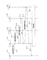
図1Aは、第1の実施形態の端末測位システムの構成図である。 FIG. 1A is a configuration diagram of a terminal positioning system according to the first embodiment.
第1の実施形態の端末測位システムは、測位サーバ(SVR)101、表示装置(DISP)102、基地局(AP1〜AP4)103、104、105及び106、及び端末(NODE)107を備える。 The terminal positioning system according to the first embodiment includes a positioning server (SVR) 101, a display device (DISP) 102, base stations (AP1 to AP4) 103, 104, 105 and 106, and a terminal (NODE) 107.
測位サーバ101は、本実施形態の端末測位システムに接続された端末107の位置を計算するコンピュータで、CPU、記憶装置及び通信インターフェースを備える。入出力装置102は、測位サーバ101に接続されたユーザインターフェースで、例えば、キーボード、マウス及びディスプレイ装置を含む。
The
基地局(AP1〜AP4)103、104、105及び106は、無線信号の送受信タイミングを測定する無線通信装置115を備える。少なくとも一つの基地局(本実施形態では、AP1)103は、測位サーバ101と有線回線によって接続される。
The base stations (AP1 to AP4) 103, 104, 105, and 106 include a
端末107は、無線送受信装置を備え、基地局103等と通信する。
The
このような端末測位システムでは、端末107の位置を測定するために、基地局103〜106の位置を確定する必要がある。このため、本発明の実施形態では、端末107の位置を測定する前に、基地局103〜106間の距離を測定し、各基地局の相対的位置を求める。
In such a terminal positioning system, it is necessary to determine the positions of the
本発明の実施形態では、基地局間で送受信される測距信号の往復時間(tij)を測定し、この往復時間に光速を乗ずることによって、基地局間の距離の2倍(dij)を求める。そして、相対座標の基準とする基地局の位置(この例では、AP1の位置p1)を座標原点として、他の基地局の相対座標(p2〜p4)を求める。 In the embodiment of the present invention, the round trip time (t ij ) of a ranging signal transmitted and received between base stations is measured, and this round trip time is multiplied by the speed of light to double the distance between base stations (d ij ). Ask for. Then, relative coordinates (p 2 to p 4 ) of other base stations are obtained using the position of the base station as a reference for the relative coordinates (in this example, the position p 1 of AP1) as the coordinate origin.
端末107の位置をN次元で求める場合、位置が既知であるN+1個の基地局が必要となる。例えば、3次元空間で端末107の位置を求める場合、4個の位置が既知の基地局が必要である。また、定まった直線上(1次元空間)で端末107の位置を求める場合、2個の位置が既知の基地局が必要である。
When the position of the
図1Bは、第1の実施形態の無線通信装置115の構成図である。
FIG. 1B is a configuration diagram of the
無線通信装置115は、Ultra wideband impulse radioを使用するUWB−IR通信装置である。
The
UWB−IR通信装置115は、アンテナ(ANT)108、スイッチ(SW)109、UWB受信機(UWB_RX)110、UWB送信機(UWB_TX)114、MAC制御部(MAC)111、データリンク制御部(DLC)112、及びカウンタ(COUNTER)113を備える。
The UWB-
アンテナ108は、基地局から送信された無線信号を捕捉し、基地局に対して無線信号を放射する。スイッチ109は、アンテナ108によって送受信される無線信号を、送信信号と受信信号とを分離する。なお、スイッチ109に代えて、デュープレクサや、サーキュレータを用いて送信信号と受信信号とを分離してもよい。
The
UWB受信機110は、基地局から送信された無線信号を受信(増幅、周波数変換及び復調)して、ベースバンド信号を生成する。UWB送信機114は、ベースバンド信号から基地局に対して送信する高周波信号を生成(変調、周波数変換及び増幅)する。
The
MAC制御部111は、パケットの送受信タイミングを制御するソフトウェア又はハードウェアによって実現され、MAC層におけるプロトコルを制御する。データリンク制御部112は、パケットの送受信タイミングを制御するソフトウェア又はハードウェアによって実現され、データリンク層におけるプロトコルを制御する。
The
カウンタ113は、無線信号の送受信タイミングを測定する。具体的には、UWB送信機114によるUWB信号の送信から、UWB受信機110によるUWB信号の受信までの時間差を測定する。この測定された時間差が信号の往復伝搬時間となる。また、UWB受信機110による1番目の信号の受信時刻と、2番目の信号の受信時刻との時間差を測定する。この測定された時間差が信号の到達時間差となる。
The
図2は、第1の実施形態のUWB−IR通信で用いられる信号波形の説明図である。 FIG. 2 is an explanatory diagram of signal waveforms used in the UWB-IR communication according to the first embodiment.
UWB−IR通信は、幅の細いパルス信号を用いる。このため、カウンタ113は受信時刻差を正確に計測することができる。
The UWB-IR communication uses a narrow pulse signal. For this reason, the
図2において、無線信号(b)を復調すると、幅の細いパルス信号(a)が得られる。例えば、このパルス幅は3ナノ秒以下(望ましくは、2ナノ秒程度)の短い時間にするとよい。 In FIG. 2, when the radio signal (b) is demodulated, a narrow pulse signal (a) is obtained. For example, the pulse width may be a short time of 3 nanoseconds or less (preferably about 2 nanoseconds).
図3は、第1の実施形態のUWB無線通信装置115の物理層部分の詳細な構成図であり、図1AにおけるMAC制御部111より左側を示す。
FIG. 3 is a detailed configuration diagram of the physical layer portion of the UWB
図3に示すUWB無線通信装置115は、アンテナ(ANT)108、スイッチ(SW)109、低雑音増幅器(LNA)301、乗算器(MIX)302、低域通過フィルタ(LPF)303、可変増幅器(VGA)304、アナログディジタル変換器(ADC)305、マッチトフィルタ(MF)306、復調部(Demoduration)307、誤り訂正復号器(FEC)308、CRC復号部(CRC)309、同期捕捉部部(Acquisition)310、同期追跡部(Tracking)311、タイミング制御部(Timing)312、分周器(1/N)313、ローカル発振器(LO)314、位相器(φ)315、フレーム生成器(Frame)316、拡散符号生成器(Spread code)317、乗算器(MIX)318、パルス生成器(Pulse)319、電力増幅器(PA)320及びカウンタ(Counter)113を備える。
3 includes an antenna (ANT) 108, a switch (SW) 109, a low noise amplifier (LNA) 301, a multiplier (MIX) 302, a low-pass filter (LPF) 303, a variable amplifier ( VGA) 304, analog-digital converter (ADC) 305, matched filter (MF) 306, demodulation unit (Demodulation) 307, error correction decoder (FEC) 308, CRC decoding unit (CRC) 309, synchronization acquisition unit (
低雑音増幅器301は、スイッチ109によって分離された受信信号を増幅する。乗算器302は、ローカル発振器314によって生成されたローカル信号と受信信号とを混合して、受信信号の周波数を変換する。低域通過フィルタ303は、乗算器302によって周波数変換された信号から所望の中間周波数の信号を選択する。可変増幅器304は、低域通過フィルタ303によって選択された信号を、所望のレベルに増幅する。
The
アナログディジタル変換器305は、可変増幅器304によって増幅されたアナログ信号をディジタル信号に変換する。マッチトフィルタ306は、アナログディジタル変換器305によって変換されたディジタル信号を、拡散符号を用いて逆拡散する。復調部307は、マッチトフィルタ306によって逆拡散された信号を復調する。誤り訂正復号器308及びCRC復号部309は、受信した信号に付されていた誤り訂正符号を用い、伝送経路中に生じた誤りを訂正する。
The analog-
同期捕捉部310は、受信信号に含まれるパルス信号を抽出し、パルス信号のタイミングを抽出する。同期追跡部311は、受信したパルス信号のタイミングを保持し、タイミング制御部312によって生成されるクロック信号とのズレを追跡し、タイミング制御部312にタイミングのズレの修正を指示する。タイミング制御部312は、アナログディジタル変換器305に供給されるクロック信号のタイミングを修正する指示を分周器313に送る。
The
分周器313は、ローカル発振器314によって生成されたローカル信号を分周し、アナログディジタル変換器313に供給するタイミング信号を生成する。ローカル発振器314は、受信信号の周波数変換に用いるローカル信号を生成する。また、ローカル発振器314によって生成されたローカル信号は分周器313によって分周され、アナログディジタル変換器305に供給され、アナログディジタル変換器305の動作の基準となるクロック信号となる。
The frequency divider 313 divides the local signal generated by the
フレーム生成器316は、MAC制御部111から送られた送信信号からフレームを生成する。拡散符号生成器317は、フレーム生成器316によって生成されたフレームを拡散するために用いられる拡散符号を生成する。
The
乗算器318は、フレーム生成器316によって生成されたフレームと、拡散符号生成器317によって生成された拡散信号を混合し、送信信号を生成する。
The multiplier 318 mixes the frame generated by the
パルス生成器319は、乗算器318によって拡散された送信信号に基づいてパルス信号を生成する。電力増幅器320は、生成されたパルス信号を所望のレベルに増幅する。
The
次に、UWB−IR通信装置115における信号の流れについて説明する。
Next, a signal flow in the UWB-
アンテナ108で受信された信号はスイッチ109を介して、低雑音増幅器301で所望のレベルに増幅される。低雑音増幅器301から出力された信号は、乗算器302、低域通過フィルタ303及びローカル発振器314によって周波数変換され、可変増幅器304によって再び増幅され、アナログディジタル変換器305に入力される。アナログディジタル変換器305では、周波数変換された受信信号はサンプリング及び量子化がされ、マッチトフィルタ306によって送信時と同じ拡散符号を用いて逆拡散される。
A signal received by the
同期捕捉部部310では、受信パルス信号と内部クロックとの同期が確立され、同期追跡部311で確立された同期が保持される。タイミング制御部312は、アナログディジタル変換器305における量子化タイミングを調整する。
The
フレーム生成器316は、送信データからパケットデータを生成し、誤り訂正符号及びCRC符号を付加し、送信すべき情報ビットを作成する。拡散符号生成器317によって生成された拡散符号と作成された情報ビットとは、乗算器318によって乗算され、拡散信号が生成される。拡散された信号は、パルス生成器319によってパルス信号に整形され、電力増幅器320で所望のレベルに増幅され、スイッチ101を介し、アンテナ108から送信される。
The
カウンタ113は、信号の送信開始から受信信号中の所定のタイミングまでの時間差を計測する。また、受信信号中の所定のタイミングから、次に到来する受信信号中の所定のタイミングまでの時間差を計測する。この所定のタイミングは、例えば、受信信号中に特定のパターンが現れた時や、パケットの受信が終了した時、などである。
The
本発明の無線通信の方式は、いかなる通信方式を用いてもよい。しかし、前述したUWB通信を用いると、高精度な時間測定が可能となり、結果的に高精度な測位が期待できる。これは、前述したように、UWB−IR通信では、幅の細いパルス信号を用いているためである。 Any communication system may be used as the wireless communication system of the present invention. However, when the above-described UWB communication is used, highly accurate time measurement is possible, and as a result, highly accurate positioning can be expected. This is because the UWB-IR communication uses a narrow pulse signal as described above.
図4は、第1の実施形態の端末測位システム全体の動作を説明するフローチャートである。 FIG. 4 is a flowchart for explaining the operation of the entire terminal positioning system according to the first embodiment.
測位サーバ101は、管理者の操作によって入出力装置102から基地局間の距離の自動測定の開始命令を受けると(S101)、測位サーバ101、基地局(AP1〜AP4)103〜106は、測距スタンバイモードに移行する(S102)。測距スタンバイモードへの移行の詳細な手順は図5を用いて後述する。
When the
測距スタンバイモードに移行した後、各基地局間の信号の往復時間に光速を乗算することによって、各基地局間の距離(d12、d13、d14、d23、d24、d34)を測定する(S103)。ここで、dijは二つの基地局(APiとAPj)との間の距離である。なお、詳細な測距手順は図6及び図7を用いて後述する。 After shifting to the distance measurement standby mode, the distance between the base stations (d 12 , d 13 , d 14 , d 23 , d 24 , d 34) is obtained by multiplying the round-trip time of the signal between the base stations by the speed of light. ) Is measured (S103). Here, d ij is a distance between two base stations (AP i and AP j ). The detailed ranging procedure will be described later with reference to FIGS.
各基地局間の距離の測定が終了した後、測位サーバ101は、受信した測距結果に基づいて、基地局(AP1〜AP4)103〜106の相対的な座標P1〜P4を計算する(S104)。すなわち、例えば、図1Aに示すように、基地局(AP1)103の座標P1を原点(0,0)とし、基地局(AP2)104をx軸上の点P2=(d12,0)とし、その他の基地局の座標を計算する。
After the measurement of the distance between the base stations is completed, the
他の基地局の座標の計算には余弦定理を用いることができる。すなわち、3辺の距離が既知で、かつ、三角形の2点(P1及びP2)が定まっている場合、余弦定理を用いることによって、他の1点(P3又はP4)の座標を計算することができる。 The cosine theorem can be used to calculate the coordinates of other base stations. That is, when the distance between the three sides is known and the two points of the triangle (P 1 and P 2 ) are fixed, the coordinates of the other point (P 3 or P 4 ) can be obtained by using the cosine theorem. Can be calculated.
但し、鏡像の関係、すなわち、残る1点のy座標の正負を、求めることはできない。 However, the relationship between mirror images, that is, the sign of the remaining y coordinate cannot be obtained.
また、評価関数を用いて最小2乗法により座標を求めることが可能である。評価関数の例として、 It is also possible to obtain coordinates by the least square method using an evaluation function. As an example of the evaluation function,

が考えられる。この評価関数は、基地局の座標の誤差を与えるものであり、この評価関数の値が最小になると、基地局の座標が最も高精度に求まっているといえる。 Can be considered. This evaluation function gives an error in the coordinates of the base station. If the value of this evaluation function is minimized, it can be said that the coordinates of the base station are obtained with the highest accuracy.
を求めることによって相対座標を求めることができる。ここで、aijは、重み付け係数であり、kは基地局の数である。 Relative coordinates can be obtained by obtaining. Here, a ij is a weighting coefficient, and k is the number of base stations.
また、既知の情報がある場合、既知の情報を用いた評価関数によって、相対座標の精度を上げることができる。例えば、基地局(AP1〜AP4)0103〜106は長方形の頂点である、ということがわかっていれば、基地局間を結ぶ直線の成す角度が垂直であることを利用し、 Further, when there is known information, the accuracy of the relative coordinates can be increased by an evaluation function using the known information. For example, if it is known that the base stations (AP1 to AP4) 0103 to 106 are rectangular vertices, the fact that the angle formed by the straight lines connecting the base stations is vertical,
とすることができる。 It can be.
以上説明したように求められた基地局の相対位置計算結果は、入出力装置102に表示される。
The base station relative position calculation result obtained as described above is displayed on the input /
その後、測位サーバ101は、相対位置の計算結果が妥当か否かを判断する(S105)。そして、計算結果が妥当でないと判断した場合、相対位置を再計算する。例えば、前述した評価関数の値と所定の閾値とを比較して、再計算が必要か否かを判断する。この再計算の要否の判断が適切かは、図8に示す計算結果の表示画面によって確認することができる。
Thereafter, the
すなわち、評価関数の値が所定の閾値を超える場合に、再計算によって基地局の座標の精度をより高める必要があると判断する。一方、評価関数の値が所定の閾値以下の場合には、計算結果は妥当なので、求められた基地局の座標の精度は充分であると判断して、基地局間測距モードを終了して、端末測位モードに移行する。 That is, when the value of the evaluation function exceeds a predetermined threshold, it is determined that it is necessary to further improve the accuracy of the coordinates of the base station by recalculation. On the other hand, if the value of the evaluation function is less than or equal to the predetermined threshold, the calculation result is valid, so it is determined that the accuracy of the obtained base station coordinates is sufficient, and the inter-base station ranging mode is terminated. , Transition to terminal positioning mode.
基地局の相対位置の誤差は、その後測定される端末の位置の誤差に伝搬するので、基地局の相対位置の誤差を一定程度に収めておく必要がある。そこで、要求される端末の測位誤差によって、基地局の相対位置の誤差を定めることが必要になる。 Since the error in the relative position of the base station propagates to the error in the position of the terminal to be measured thereafter, it is necessary to keep the error in the relative position of the base station to a certain level. Therefore, it is necessary to determine the error of the relative position of the base station according to the required positioning error of the terminal.
以上説明した判断は、管理者の意思によってもすることができる。このとき、入出力装置102に、図8に示すような計算結果を表示する。管理者は、表示された相対位置の計算結果を見て、計算結果が妥当か否かを判断する。管理者が、計算結果が妥当だと判断すると、決定ボタン910を操作することによって、端末測位モードに移行することができる。
The determination described above can also be made according to the intention of the administrator. At this time, a calculation result as shown in FIG. The administrator looks at the calculation result of the displayed relative position and determines whether or not the calculation result is valid. When the administrator determines that the calculation result is appropriate, the terminal positioning mode can be entered by operating the
一方、計算結果が妥当でないと判断した場合、再計算ボタン909を操作することによって、相対位置を再計算することができる。例えば、画面に表示された評価関数の値に基づいて、再計算が必要か否かを判断することができる。
On the other hand, if it is determined that the calculation result is not valid, the relative position can be recalculated by operating the
また、再計算するときには、計算条件ボタン908を操作することによって、評価関数を変更する等の設定を変更することができる。
When recalculation is performed, settings such as changing the evaluation function can be changed by operating the
また、各基地局間の距離を用いて相対的な座標を計算した場合、鏡像の関係の不確かさが存在するため、管理者は、鏡像ボタン906を操作することによって、鏡像の関係を選択をする。
In addition, if relative coordinates are calculated using the distances between the base stations, there is uncertainty in the mirror image relationship, so the administrator can select the mirror image relationship by operating the
一方、計算結果が妥当と判断された場合、測位サーバ101は、相対的位置関係が計算された基地局(AP1〜AP4)のうち、少なくとも一つを基準局として選択する。基準局はどのような判断基準で選んでもよいが、一つの方法として以下の方法がある。
On the other hand, when it is determined that the calculation result is valid, the
また、基準局の選択方法の例としては、他の基地局との距離の差が最も少ない局を選ぶことができる。すなわち、max(x,y,z)、min(x,y,z)をそれぞれ、x,y,zの最大値、最小値と定義すると、
AP1: max(d12,d13,d14)−min(d12,d13,d14)
AP2: max(d12,d23,d24)−min(d12,d23,d24)
AP3: max(d13,d23,d34)−min(d13,d23,d34)
AP4: max(d14,d24,d34)−min(d14,d24,d34)
で計算される値が最も小さい基地局を選択する(S106)。前述のように基準局を選択すると、基準局が各基地局のより中心に配置されることによって、端末の測位精度の向上が期待できる。
Further, as an example of a method for selecting a reference station, a station having the smallest distance difference from other base stations can be selected. That is, if max (x, y, z) and min (x, y, z) are defined as the maximum value and the minimum value of x, y, z, respectively,
AP1: max (d12, d13, d14) -min (d12, d13, d14)
AP2: max (d12, d23, d24) -min (d12, d23, d24)
AP3: max (d13, d23, d34) -min (d13, d23, d34)
AP4: max (d14, d24, d34) -min (d14, d24, d34)
The base station having the smallest value calculated in step S is selected (S106). When the reference station is selected as described above, the reference station is arranged at the center of each base station, so that improvement in the positioning accuracy of the terminal can be expected.
なお、基準局は、これ以外のどのような方法で選択してもよい。また、管理者が、計算された相対的位置関係から、基準局とする基地局を選択してもよい。 The reference station may be selected by any method other than this. Further, the manager may select a base station as a reference station from the calculated relative positional relationship.
前述した基準局が選択された後、測位サーバ101及び基地局(AP1〜AP4)103〜106を、端末測位スタンバイモードに設定する(S107)。但し、基準局として割り当てられた基地局(AP4)104は基準局としてのスタンバイモードになる。端末測位モードへの切り替えの詳細な手順は図9を用いて後述する。
After the above-described reference station is selected, the
その後、基地局(AP1〜AP4)103〜0106は、測位信号と基準信号の到達時間差を測定する。測位サーバ101は、到達時間差の測定結果に基づいて、端末の位置を測定する(S108)。その後、基地局(AP1〜AP4)103〜0106は再び、端末測位スタンバイモードに設定され、測位信号を待ち受ける。
Thereafter, the base stations (AP1 to AP4) 103 to 0106 measure the arrival time difference between the positioning signal and the reference signal. The
図5は、第1の実施形態の測距スタンバイモード移行処理の詳細な手順を示すフローチャートである。 FIG. 5 is a flowchart illustrating a detailed procedure of the distance measurement standby mode transition process according to the first embodiment.
まず、測位サーバ101は有線によって接続された基地局(AP1)103に測距待機移行指示を送信する(S111)。基地局(AP1)103は測位サーバ101から送信された測距待機移行指示を受信すると、基地局(AP2)104、基地局(AP3)105及び基地局(AP4)106に無線通信によって、測距待機指示信号を送信する(S112、S114、S116)。
First, the
基地局(AP2)104、基地局(AP3)105、基地局(AP4)106は、基地局(AP1)103から送信された測距待機指示信号を受信すると、次に送信されてくる測距信号を待ち受ける測距待機状態に移行する。この時、基地局(AP2)104、基地局(AP3)105、基地局(AP4)106は、ACK信号を送信する(S113、S115、S117)。 When the base station (AP2) 104, the base station (AP3) 105, and the base station (AP4) 106 receive the distance measurement standby instruction signal transmitted from the base station (AP1) 103, the distance measurement signal transmitted next. Shifts to the distance measurement standby state. At this time, the base station (AP2) 104, the base station (AP3) 105, and the base station (AP4) 106 transmit ACK signals (S113, S115, and S117).
なお、図5では、基地局(AP1)103は、一つの基地局に測距待機指示信号を送信し、ACK信号を受信した後、他の基地局に測距待機指示信号を送信しているが、ACK信号の到着を待たずに、他の基地局に測距待機指示信号を送信してもよい。 In FIG. 5, the base station (AP1) 103 transmits a ranging standby instruction signal to one base station, receives an ACK signal, and then transmits a ranging standby instruction signal to another base station. However, the distance measurement standby instruction signal may be transmitted to another base station without waiting for the arrival of the ACK signal.
基地局(AP1)103は、測距待機指示信号を送信した全ての基地局からACK信号を受信すると、測位サーバ101に、測距モード待機状態への移行処理の終了を通知し(S118)、測距待機状態に移行する。
When the base station (AP1) 103 receives ACK signals from all the base stations that have transmitted the distance measurement standby instruction signal, the base station (AP1) 103 notifies the
なお、本実施形態では、ACK信号を用いる例を説明したが、測距モード待機状態に移行する処理では、ACK信号は必ずしも必要ではない。 In this embodiment, an example in which an ACK signal is used has been described. However, an ACK signal is not necessarily required in the process of shifting to the distance measurement mode standby state.
図6は、第1の実施形態の基地局(AP1)103と基地局(AP2)104との間の測距手順を示すシーケンス図である。 FIG. 6 is a sequence diagram illustrating a distance measurement procedure between the base station (AP1) 103 and the base station (AP2) 104 according to the first embodiment.
まず、測位サーバ101は、AP1−AP2間の測距指示を、基地局(AP1)103に送信する(S121)。基地局(AP1)103は、測位サーバ101からAP1−AP2間の測距指示を受信すると、基地局(AP2)104に測距信号を送信する(S122)。また、基地局(AP1)103は、測距信号の送信タイミングでカウンタ113の動作を開始し、往復伝搬時間の測定を始める。
First, the
基地局(AP2)104は、基地局(AP1)103から送信された測距信号を受信すると、予め定められた時間の経過後(S123)、ACK信号を送信する(S124)。この予め定められた時間は、測位サーバが知っている時間であれば、基地局毎に同じ時間でも異なる時間でもよい。 Upon receiving the ranging signal transmitted from the base station (AP1) 103, the base station (AP2) 104 transmits an ACK signal after a predetermined time has elapsed (S123) (S124). The predetermined time may be the same time or different time for each base station as long as the positioning server knows the time.
基地局(AP1)103は、基地局(AP2)104から送信されたACK信号を受信すると、測距信号の送信によって動作を始めたカウンタ113の動作を停止し、測距信号の送信時刻と、ACK信号の受信時刻との時間差を測定する(S125)。基地局(AP1)103は、時間差の測定結果を、測位サーバ101に送信する(S126)。
When the base station (AP1) 103 receives the ACK signal transmitted from the base station (AP2) 104, the base station (AP1) 103 stops the operation of the
例えば、時間差の測定時間がT1、基地局(AP2)104における予め定められた時間をT2とすると、距離d12は
d12=(T1−T2)×C
で求めることができる。但し、Cは光速である。
For example, if the measurement time of the time difference is T1, and the predetermined time in the base station (AP2) 104 is T2, the distance d12 is d12 = (T1-T2) × C
Can be obtained. Where C is the speed of light.
図7は、第1の実施形態の基地局(AP2)104と基地局(AP3)105との間の測距手順を示すシーケンス図である。 FIG. 7 is a sequence diagram illustrating a distance measurement procedure between the base station (AP2) 104 and the base station (AP3) 105 according to the first embodiment.
まず、測位サーバ101は、AP2−AP3間の測距指示を基地局(AP1)103に送信する(S131)。基地局(AP1)103は、測位サーバ101からAP2−AP3間の測距指示を受信すると、基地局(AP2)104に、測距指示信号(AP2−AP3)を送信する(S132)。
First, the
基地局(AP2)104は、基地局(AP1)103から測距指示信号(AP2−AP3)を受信すると、基地局(AP3)105に測距信号を送信する(S133)。基地局(AP3)105は、基地局(AP2)から送信された測距信号を受信すると、予め定められた時間の経過後(S134)、ACK信号を送信する(S135)。 When receiving the ranging instruction signal (AP2-AP3) from the base station (AP1) 103, the base station (AP2) 104 transmits the ranging signal to the base station (AP3) 105 (S133). Upon receiving the distance measurement signal transmitted from the base station (AP2), the base station (AP3) 105 transmits an ACK signal after elapse of a predetermined time (S134) (S135).
基地局(AP2)104は、測距信号の送信時刻と、ACK信号の受信時刻との差を測定する(S136)。基地局(AP2)104は、時間差の測定結果を、基地局(AP1)103に送信する。基地局(AP1)103は、基地局(AP2)104から時刻差の測定結果を受信すると、受信した測定結果を測位サーバ101に送信する。
The base station (AP2) 104 measures the difference between the transmission time of the distance measurement signal and the reception time of the ACK signal (S136). The base station (AP2) 104 transmits the time difference measurement result to the base station (AP1) 103. Upon receiving the time difference measurement result from the base station (AP2) 104, the base station (AP1) 103 transmits the received measurement result to the
他の基地局間の距離も図6及び図7に示された手順と同様の手順によって求められる。 The distances between other base stations are also obtained by a procedure similar to the procedure shown in FIGS.
図8は、第1の実施形態の相対座標計算結果の表示例を示す。 FIG. 8 shows a display example of the relative coordinate calculation result of the first embodiment.
基地局の相対位置の計算結果が表示される表示ウィンドウ901は、画像による結果表示902、数値による結果表示903、基準局選択ボタン904、地図読込ボタン905、鏡像ボタン906、回転ボタン907、計算条件変更ボタン908、再計算ボタン909及び決定ボタン910を含む。
A
結果表示902には、計算された各基地局の相対位置が画像によって、適切な座標軸上に表示される。結果表示903には、計算された各基地局の相対位置がxy座標を用いた数値によって表示される。基準局選択ボタン904は、基準局とする基地局を選択するときに使用される。
In the
地図読込ボタン905は、相対位置が計算された基地局が含まれる領域の地図が、計算された各基地局の相対座標に重畳させて表示するときに操作される。
The
鏡像ボタン906は、計算された各基地局の相対座標を、横軸(AP1及びAP2が位置する軸)を軸として反転するときに操作される。なお、反転軸を自由に設定できるようにしてもよい。回転ボタン907は、表示された地図又は表示された相対位置を回転するときに操作される。
The
計算条件変更ボタン908は、評価関数等の計算条件を変えるときに操作される。再計算ボタン909は、計算された各基地局の相対位置を再度計算するときに操作される。決定ボタン910は、端末測位モードに移行するときに操作される。
A calculation
図9は、第1の実施形態の端末測位モードへの切替手順を示すシーケンス図である。 FIG. 9 is a sequence diagram illustrating a procedure for switching to the terminal positioning mode according to the first embodiment.
この端末測位モードへの切り替えは、基地局間の相対座標が評価され(図4のS105)、基準局の選択の後(図4のS106)、端末測位モードに切り替えるものである。 In this switching to the terminal positioning mode, the relative coordinates between the base stations are evaluated (S105 in FIG. 4), and after switching to the reference station (S106 in FIG. 4), switching to the terminal positioning mode is performed.
まず、測位サーバ101は、端末測位待機指示及び基準局割当指示を基地局(AP1)103に送信する(S141)。基地局(AP1)103は、測位サーバ101から端末測位待機指示及び基準局割当指示を受信すると、基準局となる基地局を特定する。そして、基準局とならない基地局(AP2)104及び基地局(AP3)105に、端末測位待機指示信号を送信する(S142、S144)。基準局とならない基地局(AP2)104及び基地局(AP3)105は、端末から送信される測位信号を待ち受ける測位基地局モード待機状態に移行し(S150)、基地局(AP1)にACK信号を返信する(S143、S145)。
First, the
さらに、基地局(AP1)103は、基準局として動作する基地局(AP4)105に、端末測位待機指示信号及び基準局割当信号を送信する(S146)。基準局として動作する基地局(AP4)106は、基準局として端末から送信される測位信号を待ち受ける測位基準局モード待機状態に移行し(S147)、基地局(AP1)にACK信号を返信する(S148)。 Further, the base station (AP1) 103 transmits a terminal positioning standby instruction signal and a reference station assignment signal to the base station (AP4) 105 operating as a reference station (S146). The base station (AP4) 106 operating as a reference station shifts to a positioning reference station mode standby state waiting for a positioning signal transmitted from a terminal as a reference station (S147), and returns an ACK signal to the base station (AP1) (S148).
なお、図9では、基地局(AP1)103は、一つの基地局に端末測位待機指示信号を送信し、ACK信号を受信すると、他の基地局に端末測位待機指示信号を送信しているが、ACK信号の到着を待たずに、他の基地局に端末測位待機指示信号を送信してもよい。 In FIG. 9, the base station (AP1) 103 transmits a terminal positioning standby instruction signal to one base station and, when receiving an ACK signal, transmits a terminal positioning standby instruction signal to another base station. The terminal positioning standby instruction signal may be transmitted to another base station without waiting for the arrival of the ACK signal.
基地局(AP1)103は、測距待機指示信号を送信した全ての基地局からACK信号を受信すると、基地局(AP1)103は、測位サーバ101に、端末測位モード待機状態への移行処理の終了を通知し(S149)、測位基地局モード待機状態に移行する(S150)。
When the base station (AP1) 103 receives ACK signals from all the base stations that have transmitted the ranging standby instruction signal, the base station (AP1) 103 causes the
なお、本実施形態では、ACK信号を用いる例を説明したが、端末測位モード待機状態に移行するためには、ACK信号は必ずしも必要ではない。 In this embodiment, an example in which an ACK signal is used has been described. However, an ACK signal is not necessarily required in order to shift to the terminal positioning mode standby state.
図10は、第1の実施形態の端末の位置測定の手順を示すシーケンス図である。 FIG. 10 is a sequence diagram illustrating a procedure for measuring the position of the terminal according to the first embodiment.
まず、端末107が、近隣の基地局に対し測位信号を送信する(S151)。基準局として動作する基地局(AP4)106は、端末107から送信された測位信号を受信すると、予め定められた時間の後、近隣の基地局に対し基準信号を送信する(S152)。 First, the terminal 107 transmits a positioning signal to neighboring base stations (S151). When receiving the positioning signal transmitted from the terminal 107, the base station (AP4) 106 operating as the reference station transmits a reference signal to neighboring base stations after a predetermined time (S152).
一方、基準局として動作しない基地局(AP1)103、基地局(AP2)104及び基地局(AP3)105は、端末107から送信された測位信号を受信すると、カウンタ113の動作を開始し、到達時間差の測定を始める。そして、基地局(AP1)103、基地局(AP2)104及び基地局(AP3)105は、基準局(AP4)106から送信された基準信号を受信すると、測位信号の受信によって動作を始めたカウンタ113の動作を停止し、測位信号と基準信号の到達時間差を測定する(S153、S154、S155)。
On the other hand, when the base station (AP1) 103, the base station (AP2) 104, and the base station (AP3) 105 that do not operate as the reference station receive the positioning signal transmitted from the terminal 107, the base station (AP1) 103 starts the operation of the
基地局(AP2)104及び基地局(AP3)105は、到達時間差の測定結果を基地局(AP1)103に無線通信にて通知する(S156、S158)。基地局(AP1)103は、基地局(AP2)104及び基地局(AP3)105から測定結果を受信すると、測定結果の送信元の基地局にACK信号を返信する(S157、S159)。 The base station (AP2) 104 and the base station (AP3) 105 notify the measurement result of the arrival time difference to the base station (AP1) 103 by wireless communication (S156, S158). When the base station (AP1) 103 receives the measurement results from the base station (AP2) 104 and the base station (AP3) 105, the base station (AP1) 103 returns an ACK signal to the base station that transmitted the measurement results (S157, S159).
その後、基地局(AP1)103は、測位サーバ101に、他の基地局から受信した全ての測定結果及び、自局で測定した到達時間差の測定結果を通知する(S160)。測位サーバ101は、各基地局(AP1〜AP3)103〜105における到達時間差の測定結果と、各基地局(AP1〜AP3)103〜105の相対座標の計算結果とに基づいて、端末の位置を計算する(S161)。
Thereafter, the base station (AP1) 103 notifies the
その後、基地局(AP1〜AP3)103〜105は、再び、測位基地局モード待機状態に設定される。また、基準局として動作する基地局(AP4)106は、再び、測位基準局モード待機状態に設定される。 Thereafter, the base stations (AP1 to AP3) 103 to 105 are again set to the positioning base station mode standby state. In addition, the base station (AP4) 106 operating as the reference station is set again to the positioning reference station mode standby state.
ここで、到達時間差を用いた測位の方法について説明する。 Here, a positioning method using the arrival time difference will be described.
端末の位置は、端末からの信号と基準局からの信号との到達時間差に基づいて求められる。すなわち、各基地局が、端末からの信号の受信時刻と基準局からの信号の受信時刻との差(T1−T2)を求める。この信号の受信時刻の差は、受信局と端末との距離(L1)と、受信局と基準局との距離(L2)との差(L1−L2)を信号の伝搬速度(光速)で除したものとなる。 The position of the terminal is obtained based on the arrival time difference between the signal from the terminal and the signal from the reference station. That is, each base station obtains the difference (T1-T2) between the reception time of the signal from the terminal and the reception time of the signal from the reference station. The difference in the reception time of this signal is obtained by dividing the difference (L1-L2) between the distance (L1) between the receiving station and the terminal and the distance (L2) between the receiving station and the reference station by the signal propagation speed (light speed). It will be a thing.
すなわち、受信局は、受信局と端末の距離及び受信局と基準局の距離の差が一定(L1−L2)となる双曲線上に存在する。この双曲線は、端末の位置と基準局の位置を焦点とする曲線となる。 In other words, the receiving station exists on a hyperbola where the difference between the distance between the receiving station and the terminal and the distance between the receiving station and the reference station is constant (L1-L2). This hyperbola is a curve that focuses on the position of the terminal and the position of the reference station.
また、他の二つの基地局でも、端末からの信号と基準局からの信号とを受信し、両信号の到達時間差を求め、双曲線を算出する。これによって、端末が存在する位置は、この3本の双曲線の焦点であることが分かる。 Further, the other two base stations also receive the signal from the terminal and the signal from the reference station, determine the arrival time difference between the two signals, and calculate the hyperbola. Thus, it can be seen that the position where the terminal exists is the focal point of these three hyperbolic curves.
このように、複数の基地局が受信した信号の到達時間差に基づいて端末の位置を測定すると、端末からの信号の伝搬遅延時間に光速を乗じて求められた距離によって端末の位置を測定する方法と比べて、測定された伝搬遅延時間(T1、T2)に共通する時間の誤差が含まれていても、これを消去できる特徴がある。 As described above, when the position of the terminal is measured based on the arrival time difference between signals received by a plurality of base stations, the position of the terminal is measured by the distance obtained by multiplying the propagation delay time of the signal from the terminal by the speed of light. As compared with the above, there is a feature that even if a time error common to the measured propagation delay times (T1, T2) is included, this can be eliminated.
なお、これまで、端末からの測位信号と基準局からの基準信号との到達時間差を計測することによって、端末の位置を測定する方式について説明してきたが、本発明の目的とするところは、複数の基地局を用いて端末の測位を行うシステムにおける、基地局の位置を求めることにある。よって、到達時間差を用いる測位方法ではなくても、本発明を適用できることは自明である。 Up to now, the method of measuring the position of the terminal by measuring the arrival time difference between the positioning signal from the terminal and the reference signal from the reference station has been described. The purpose is to determine the position of a base station in a system for positioning a terminal using the base station. Therefore, it is obvious that the present invention can be applied even if the positioning method does not use the arrival time difference.
前述したように、第1の実施形態では、基地局間の距離の測定には信号の伝搬時間を用い、端末の位置の測定には信号の伝搬時間差を用いる。このようにしたのは、信号の伝搬時間差を用いた位置測定は、前述したように共通の誤差を除去することができる優れた方法であるが、位置が既知の基地局が必要である。よって、測位システムの構築時には基地局の位置は未知であることから、信号の伝搬時間差を用いた位置測定方法を用いることができない。しかし、測位システムの構築時には、迅速に測定をする必要がないので、繰り返し測定をすることによって、基地局間の距離の精度を向上させることができる。よって、本実施形態のような、基地局間の距離の測定には信号の伝搬時間を用い、端末の位置の測定には信号の伝搬時間差を用いるものが最適である。 As described above, in the first embodiment, the signal propagation time is used to measure the distance between base stations, and the signal propagation time difference is used to measure the terminal position. This is because the position measurement using the signal propagation time difference is an excellent method capable of removing the common error as described above, but a base station having a known position is required. Therefore, since the position of the base station is unknown when the positioning system is constructed, it is not possible to use a position measurement method using a difference in signal propagation time. However, since it is not necessary to measure quickly when the positioning system is constructed, the accuracy of the distance between base stations can be improved by performing repeated measurements. Therefore, as in this embodiment, it is optimal to use the signal propagation time for measuring the distance between base stations and to use the signal propagation time difference for measuring the terminal position.
第1の実施形態によると、端末測位システムを構築する際に、複数の基地局を配置するのみで、設置された基地局の位置を正確に測定することなく、無線通信によって基地局の相対的座標を求めることができる。よって、基地局設置時の人手の作業を省き、端末測位システムの初期導入を簡単化することができる。 According to the first embodiment, when constructing a terminal positioning system, it is only necessary to arrange a plurality of base stations, and accurately measure the relative positions of the base stations by wireless communication without accurately measuring the positions of the installed base stations. Coordinates can be obtained. Therefore, it is possible to simplify the initial introduction of the terminal positioning system by omitting the manual work when installing the base station.
また、各基地局間は無線通信によって信号を送受信するので、有線による通信線の敷設を省略することができ、基地局の配置の自由度をあげることができる。 In addition, since signals are transmitted and received between the base stations by wireless communication, it is possible to omit the installation of a wired communication line and to increase the degree of freedom of the arrangement of the base stations.
以上説明したように第1の実施形態によると、端末測位システムの構築時に、複数の基地局を配置するのみで、人手によって基地局の設置位置を計測する必要がなく、無線通信によって基地局の相対的座標を求めることができるので、端末測位システムの導入を簡単化することができる。 As described above, according to the first embodiment, when a terminal positioning system is constructed, it is only necessary to arrange a plurality of base stations, and there is no need to manually measure the installation positions of the base stations. Since the relative coordinates can be obtained, the introduction of the terminal positioning system can be simplified.
また、各基地局間は無線によって通信するので、配線の敷設する必要がなく、基地局の配置の自由度を向上させることができる。 In addition, since the base stations communicate with each other wirelessly, there is no need to lay wiring, and the degree of freedom in arranging the base stations can be improved.
また、新しく基地局を追加する際も、無線通信によって基地局の相対的座標を求めることができ、人手の作業を省き、端末測位システムの拡大を簡単化することができる。 In addition, when a new base station is added, the relative coordinates of the base station can be obtained by wireless communication, so that manual work can be saved and the expansion of the terminal positioning system can be simplified.
(実施形態2)
次に、本発明の第2の実施形態について説明する。
(Embodiment 2)
Next, a second embodiment of the present invention will be described.
図11は、本発明の第2の実施形態の端末測位システムの構成図である。 FIG. 11 is a configuration diagram of a terminal positioning system according to the second embodiment of this invention.
第1の実施形態では、測位サーバ101が基地局(AP1)103と有線によって接続されていたが、以下に説明する第2の実施形態では、各基地局(AP1〜AP4)1403〜1406が測位サーバ1401と無線によって接続される。すなわち、第1の実施形態で説明した測位サーバ101と基地局(AP1)103との有線通信に代わって、第2の実施形態では、各基地局(AP1〜AP4)1403〜1406が、直接、測位サーバ1401と無線通信をする。
In the first embodiment, the
この基地局(AP1〜AP4)1403〜1406と、測位サーバ1401との間の上位の無線通信方式を無線LANとし、基地局(AP1〜AP4)1403〜1406間の下位の無線通信方式をUWBとして、両システムを異なるものとしたが、同じ方式を用いてもよい。
The upper wireless communication system between the base stations (AP1 to AP4) 1403 to 1406 and the
第2の実施形態の端末測位システムは、測位サーバ(SVR)1401、表示装置(DISP)1402、基地局(AP1〜AP4)1403、1404、1405、1406、及び端末(NODE)1407を備える。 The terminal positioning system of the second embodiment includes a positioning server (SVR) 1401, a display device (DISP) 1402, base stations (AP1 to AP4) 1403, 1404, 1405, 1406, and a terminal (NODE) 1407.
第2の実施形態の測位サーバ1401は、第1の実施形態の測位サーバ101と同一の構成を備える。さらに、第2の実施形態の測位サーバ1401は、各基地局(AP1〜AP4)1403〜1406と無線によって通信する無線送受信部を備える。
The
また、第2の実施形態の各基地局(AP1〜AP4)1403〜1406は、第1の実施形態の基地局(AP1〜AP4)103〜106と同一の構成を備える。また、第2の実施形態の基地局1403〜1406は、測位サーバ1401と無線によって通信する無線送受信部を備える。
In addition, the base stations (AP1 to AP4) 1403 to 1406 of the second embodiment have the same configuration as the base stations (AP1 to AP4) 103 to 106 of the first embodiment. In addition, the
前述した測位サーバ1401及び基地局1403〜1406が備える無線送受信部は、第1の実施形態で説明した、測距及び/又は測位に用いる無線通信方式と同一の無線通信方式を用いてもよいし、他の無線通信方式を用いてもよい。例えば、他の無線通信方式として、無線LANが考えられる。
The wireless transmission / reception units included in the
また、第2の実施形態の表示装置1402、端末1407は、各々、第1の実施形態の測位サーバ101、表示装置102、端末107と同一の構成を備える。
Further, the
次に、本発明の第2の実施形態における基地局間の動作手順を説明する。 Next, an operation procedure between base stations in the second embodiment of the present invention will be described.
前述した第1の実施形態では、測位サーバ1401からの全ての信号は、基地局(AP1)1403を経由していたが、第2の実施形態では、測位サーバ1401からの信号は、直接、全ての基地局(AP1〜AP4)1403〜1406に送信される。この点を除いて、前述した第1の実施形態の処理(図5、図7、図9及び図10参照)とおなじである。
In the first embodiment described above, all signals from the
以上説明したように、第2の実施形態によると、いずれの基地局にも有線による接続が不要になり、各基地局への配線を不要にすることができる。このため、基地局の設置導入を簡単化し、基地局の設置の自由度を増すことができる。 As described above, according to the second embodiment, no wired connection is required for any base station, and wiring to each base station can be eliminated. For this reason, it is possible to simplify the installation of the base station and increase the degree of freedom in installing the base station.
(実施形態3)
次に、本発明の第3の実施形態について説明する。
(Embodiment 3)
Next, a third embodiment of the present invention will be described.
図12は、本発明に係る第3の実施形態の端末測位システムの構成図である。 FIG. 12 is a configuration diagram of a terminal positioning system according to the third embodiment of the present invention.
第3の実施形態の端末測位システムは、測位サーバ(SVR)1501、表示装置(DISP)1502、基地局(AP1〜AP6)1503、1504、1505、1506、1507、1508、及び端末(NODE)1509を備える。第3の実施形態では、基地局(AP2)1504、基地局(AP3)1505、基地局(AP5)1507、基地局(AP6)1508によって、第1の実施形態と同様の端末測位システムを構築する。すなわち、基地局の通信範囲を超えて基地局を設置するので、端末の位置測定が可能な領域が第1の実施形態より拡大する。 A terminal positioning system according to the third embodiment includes a positioning server (SVR) 1501, a display device (DISP) 1502, base stations (AP1 to AP6) 1503, 1504, 1505, 1506, 1507, 1508, and a terminal (NODE) 1509. Is provided. In the third embodiment, a base station (AP2) 1504, a base station (AP3) 1505, a base station (AP5) 1507, and a base station (AP6) 1508 are used to construct a terminal positioning system similar to that of the first embodiment. . That is, since the base station is installed beyond the communication range of the base station, the area where the position of the terminal can be measured is expanded as compared with the first embodiment.
第3の実施形態の基地局(AP1〜AP6)1503〜1508は、基地局(AP1〜AP4)と同一の構成を備える。さらに、基地局(AP2)1504及び基地局(AP3)1505は、基地局(AP1)1501と無線によって通信する無線送受信部を備える。また、基地局(AP2)1504及び基地局(AP3)1505は、基地局(AP5)1507及び基地局(AP6)1508と無線によって通信する無線送受信機能を備える。これによって、基地局(AP2)1504及び基地局(AP3)1505は、基地局(AP5)1507及び基地局(AP6)1508から送信された信号を、基地局(AP1)1503に中継することができる。 The base stations (AP1 to AP6) 1503 to 1508 of the third embodiment have the same configuration as the base stations (AP1 to AP4). Furthermore, the base station (AP2) 1504 and the base station (AP3) 1505 include a wireless transmission / reception unit that communicates with the base station (AP1) 1501 by radio. Further, the base station (AP2) 1504 and the base station (AP3) 1505 have a wireless transmission / reception function for communicating with the base station (AP5) 1507 and the base station (AP6) 1508 by radio. Accordingly, the base station (AP2) 1504 and the base station (AP3) 1505 can relay the signals transmitted from the base station (AP5) 1507 and the base station (AP6) 1508 to the base station (AP1) 1503. .
この基地局(AP1)1501と、基地局(AP2)1504及び基地局(AP3)1505との間の上位の無線通信方式をUWBとし、基地局(AP2〜AP6)1504〜1508間の下位の無線通信方式をUWBとし、両システムを同じにしたが、異なる無線通信方式を用いてもよい。例えば、上位の無線通信方式を無線LANとし、下位の無線通信方式をUWBとすることもできる。 The upper wireless communication system between the base station (AP1) 1501, the base station (AP2) 1504, and the base station (AP3) 1505 is UWB, and the lower wireless between the base stations (AP2 to AP6) 1504 to 1508. Although the communication method is UWB and both systems are the same, different wireless communication methods may be used. For example, the upper wireless communication method can be a wireless LAN, and the lower wireless communication method can be UWB.
第3の実施形態の測位サーバ1501、表示装置1502、端末1509は、各々、第1の実施形態の測位サーバ101、表示装置102、端末0107と同一の構成を備える。
The
基地局(AP2)1504、基地局(AP3)1505、基地局(AP5)1507、基地局(AP6)1508によって構築される端末測位システムの動作は、第1の実施形態(図4)の、測位サーバ101を測位サーバ1501に、基地局(AP1〜AP4)103〜106を、基地局(AP1〜AP6)1503〜1508に、端末107を端末1509に置き換えたもので説明できる。具体的には以下の通りである。
The operation of the terminal positioning system constructed by the base station (AP2) 1504, the base station (AP3) 1505, the base station (AP5) 1507, and the base station (AP6) 1508 is the positioning of the first embodiment (FIG. 4). This can be explained by replacing the
図13は、第3の実施形態の基地局(AP5)1507と基地局(AP6)1508との間の測距手順を示すシーケンス図である。 FIG. 13 is a sequence diagram illustrating a distance measurement procedure between the base station (AP5) 1507 and the base station (AP6) 1508 according to the third embodiment.
まず、測位サーバ1501は、AP5−AP6間の測距指示信号を基地局(AP1)1503に送信する(S171)。測位サーバ1501は各基地局への信号の転送経路を示すルーティング情報を保持しており、上記測距指示信号と共にルーティング情報が送信される。
First, the
基地局(AP1)1503は、測位サーバ1501からAP5−AP6間の測距指示を受信すると、測位サーバ1501から送信されたルーティング情報を参照し、基地局(AP5)1507への経路となる基地局(AP2)1504を特定し、特定された基地局(AP2)1504に測距指示信号(AP5−AP6)を送信する(S172)。基地局(AP2)1504は、基地局(AP1)1503から送信された測距指示信号を受信すると、基地局(AP5)1507に測距指示信号(AP5−AP6)を送信する(S173)。
When the base station (AP1) 1503 receives a ranging instruction between the AP5 and AP6 from the
基地局(AP5)1507は、基地局(AP2)1504によって転送された測距指示信号を受信すると、基地局(AP6)1508に測距信号を送信する(S174)。また、基地局(AP5)1507は、測距信号の送信タイミングでカウンタ113の動作を開始し、往復伝搬時間の測定を始める。
When receiving the ranging instruction signal transferred by the base station (AP2) 1504, the base station (AP5) 1507 transmits the ranging signal to the base station (AP6) 1508 (S174). Also, the base station (AP5) 1507 starts the operation of the
基地局(AP6)1508は、基地局(AP5)1507から送信された測距信号を受信すると、予め定められた時間の経過後(S175)、ACK信号を送信する(S176)。 When the base station (AP6) 1508 receives the ranging signal transmitted from the base station (AP5) 1507, the base station (AP6) 1508 transmits an ACK signal after elapse of a predetermined time (S175) (S176).
基地局(AP5)1507は、基地局(AP6)1508から送信されたACK信号を受信すると、測距信号の送信によって動作を始めたカウンタ113の動作を停止し、測距信号の送信時刻と、ACK信号の受信時刻との差を測定する(S177)。受信した測定結果は、測距指示信号と逆のルートで、基地局(AP2)1504及び基地局(AP1)1503を経由して、測位サーバ 1501に送信される。
When the base station (AP5) 1507 receives the ACK signal transmitted from the base station (AP6) 1508, the base station (AP5) 1507 stops the operation of the
図14は、第3の実施形態の端末測位モードへの切替手順を示すシーケンス図である。 FIG. 14 is a sequence diagram illustrating a procedure for switching to the terminal positioning mode according to the third embodiment.
図14に示す例においては、基地局(AP4)1506と基地局(AP6)1508とが基準局として選択される。 In the example shown in FIG. 14, the base station (AP4) 1506 and the base station (AP6) 1508 are selected as reference stations.
まず、測位サーバ1501は、端末測位待機指示及び基地局割当指示を基地局(AP1)1503に送信する(S181)。基地局(AP1)1503は、測位サーバ101から端末測位待機指示及び基準局割当指示を受信すると、端末測位待機指示と共に送信されるルーティング情報を参照し、宛先の基地局(AP5)1507及び基地局(AP6)1508への経路となる基地局(AP2)1504を特定する。そして、特定された基地局(AP2)1504に端末測位待機指示信号及び基準局割当指示を送信する(S182)。
First, the
基地局(AP2)1504は、基地局(AP1)1503から送信された端末測位待機指示信号を受信すると、端末測位待機指示信号に含まれる基準局割当情報を抽出し、基準局となる基地局を特定する。基地局(AP2)1504は、基準局とならない基地局(AP5)1507に端末測位待機指示信号を送信し(S183)、基準局となる基地局(AP6)1508に端末測位待機指示信号及び基準局割当信号を送信する(S185)。 When the base station (AP2) 1504 receives the terminal positioning standby instruction signal transmitted from the base station (AP1) 1503, the base station (AP2) 1504 extracts the reference station allocation information included in the terminal positioning standby instruction signal, and specifies the base station serving as the reference station . The base station (AP2) 1504 transmits a terminal positioning standby instruction signal to the base station (AP5) 1507 that is not the reference station (S183), and transmits the terminal positioning standby instruction signal and the reference station allocation signal to the base station (AP6) 1508 that is the reference station. Transmit (S185).
基地局(AP5)1507及び基地局(AP6)1508は、基地局(AP2)1504から端末測位待機指示信号を受信すると、ACK信号を返信し(S184、S186)、端末測位待機状態に移行する(S193、S194)。 When the base station (AP5) 1507 and the base station (AP6) 1508 receive the terminal positioning standby instruction signal from the base station (AP2) 1504, the base station (AP5) 1507 returns an ACK signal (S184, S186), and shifts to the terminal positioning standby state ( S193, S194).
また、基地局(AP1)1503は、基準局とならない基地局(AP3)1505に端末測位待機指示信号を送信し(S186)、基準局となる基地局(AP4)1506に端末測位待機指示信号及び基準局割当信号を送信する(S188)。基地局(AP3)1505及び基地局(AP4)1506は、基地局(AP1)1503から端末測位待機指示信号を受信すると、ACK信号を返信し(S187、S189)、端末測位待機状態に移行する(S193、S194)。 Also, the base station (AP1) 1503 transmits a terminal positioning standby instruction signal to the base station (AP3) 1505 that is not the reference station (S186), and the terminal positioning standby instruction signal and the reference station assignment are transmitted to the base station (AP4) 1506 that is the reference station. A signal is transmitted (S188). Upon receiving the terminal positioning standby instruction signal from the base station (AP1) 1503, the base station (AP3) 1505 and the base station (AP4) 1506 return an ACK signal (S187, S189), and shift to the terminal positioning standby state ( S193, S194).
基地局(AP4)1506と、基地局(AP6)1507とは、端末測位待機指示信号と共に基準局割当信号も受信するので、基準局として端末から送信される測位信号を待ち受ける測位基準局モード待機状態に移行する(S193)。 Since the base station (AP4) 1506 and the base station (AP6) 1507 receive the reference station assignment signal together with the terminal positioning standby instruction signal, the base station (AP6) 1507 shifts to a positioning reference station mode standby state that waits for a positioning signal transmitted from the terminal as a reference station. (S193).
図15は、第3の実施形態の端末の位置測定の手順を示すシーケンス図である。 FIG. 15 is a sequence diagram illustrating a procedure of position measurement of the terminal according to the third embodiment.
まず、端末1509が、近隣の基地局に対し測位信号を送信する(S201)。基準局として動作する基地局(AP6)1508は、端末1509から送信された測位信号を受信すると、予め定められた時間の後、近隣の基地局に対し基準信号を送信する(S202)。 First, the terminal 1509 transmits a positioning signal to a neighboring base station (S201). When receiving the positioning signal transmitted from the terminal 1509, the base station (AP6) 1508 operating as the reference station transmits a reference signal to the neighboring base stations after a predetermined time (S202).
一方、基準局として動作しない基地局(AP2)1504、基地局(AP3)1505及び基地局(AP5)1506は、端末1509から送信された測位信号を受信すると、カウンタ113の動作を開始し、受信時間差の測定を始める。そして、基地局(AP2)1504、基地局(AP3)1505及び基地局(AP5)1506は、基準局(AP6)1508から送信された基準信号を受信すると、測位信号の受信によって動作を始めたカウンタ113の動作を停止し、測位信号と基準信号の到達時間差を測定する(S203、S204、S205)。
On the other hand, when the base station (AP2) 1504, the base station (AP3) 1505, and the base station (AP5) 1506 that do not operate as the reference station receive the positioning signal transmitted from the terminal 1509, the base station (AP2) 1504 starts the operation of the
基地局(AP3)1506は、到達時間差の測定結果を基地局(AP1)1503に無線通信にて通知する(S206)。基地局(AP1)1503は、基地局(AP3)1506から測定結果を受信すると、測定結果の送信元の基地局にACK信号を返信する(S207)。 The base station (AP3) 1506 notifies the measurement result of the arrival time difference to the base station (AP1) 1503 by wireless communication (S206). When the base station (AP1) 1503 receives the measurement result from the base station (AP3) 1506, the base station (AP1) 1503 returns an ACK signal to the base station that has transmitted the measurement result (S207).
基地局(AP5)1506は、到達時間差の測定結果を基地局(AP2)1504に無線通信にて通知する(S208)。基地局(AP2)1504は、基地局(AP5)から送信された測定結果を、基地局(AP1)1503に転送する(S209)。このとき、基地局(AP2)1504は、自己の到達時間差の測定結果を、併せて、基地局(AP1)1503に無線通信にて送信する(S209)。 The base station (AP5) 1506 notifies the measurement result of the arrival time difference to the base station (AP2) 1504 by wireless communication (S208). The base station (AP2) 1504 transfers the measurement result transmitted from the base station (AP5) to the base station (AP1) 1503 (S209). At this time, the base station (AP2) 1504 also transmits the measurement result of its own arrival time difference to the base station (AP1) 1503 by wireless communication (S209).
基地局(AP1)1503は、基地局(AP2)1504から測定結果を受信すると、測定結果の送信元の基地局(AP2)1504にACK信号を返信する(S210)。基地局(AP2)1504は、基地局(AP1)1503からACK信号を受信すると、測定結果の送信元の基地局(AP5)1507にACK信号を返信する(S211)。 Upon receiving the measurement result from the base station (AP2) 1504, the base station (AP1) 1503 returns an ACK signal to the base station (AP2) 1504 that is the transmission source of the measurement result (S210). When the base station (AP2) 1504 receives the ACK signal from the base station (AP1) 1503, the base station (AP2) 1504 returns the ACK signal to the base station (AP5) 1507 of the measurement result transmission source (S211).
基地局(AP1)1503は測位サーバ1501に、他の基地局から受信した全ての測定結果を通知する(S212)。測位サーバ1501は、各基地局(AP2〜AP5)1504〜1507における到達時間差の測定結果と、各基地局(AP2〜AP5)1504〜1507の相対座標の計算結果とに基づいて、端末の位置を計算する(S213)。
The base station (AP1) 1503 notifies the
その後、基地局(AP2〜AP6)1503〜1508は、再び、測位基地局モード待機状態に設定される。また、基準局として動作する基地局(AP6)1508は、再び、測位基準局モード待機状態に設定される。 Thereafter, the base stations (AP2 to AP6) 1503 to 1508 are again set to the positioning base station mode standby state. Further, the base station (AP6) 1508 operating as the reference station is set again to the positioning reference station mode standby state.
前述したように、第3の実施形態によると、端末測位エリアを拡大するために、新しい基地局を追加する際も、複数の基地局を配置するのみで、人手によって基地局の設置位置を正確に測定することなく、無線通信によって基地局の相対的座標を求めることができるので、端末測位システムの拡充を簡単化することができる。また、各基地局は無線によって中継され、測位サーバと通信するので、優先による通信線の敷設を省略することがでる。また、基地局の配置の自由度をあげることができる。 As described above, according to the third embodiment, when a new base station is added in order to expand the terminal positioning area, it is only necessary to arrange a plurality of base stations, and the base station installation position can be accurately determined manually. Since the relative coordinates of the base station can be obtained by wireless communication without making a measurement, the expansion of the terminal positioning system can be simplified. Further, since each base station is relayed wirelessly and communicates with the positioning server, it is possible to omit the laying of communication lines with priority. Moreover, the freedom degree of arrangement | positioning of a base station can be raised.
101、1401、1501 測位サーバ(SRV)
102、1402、1502 表示装置(DISP)
103、104、105、106、1403、1404、1405、1406、1503、1504、1505、1506、1507 基地局(AP)
115 無線通信装置
110 UWB受信器(UWB_RX)
114 UWB送信器(UWB_TX)
113 カウンタ(COUNTER)
101, 1401, 1501 Positioning server (SRV)
102, 1402, 1502 Display device (DISP)
103, 104, 105, 106, 1403, 1404, 1405, 1406, 1503, 1504, 1505, 1506, 1507 Base station (AP)
115
114 UWB transmitter (UWB_TX)
113 Counter (COUNTER)
Claims (20)
前記少なくとも(N+1)個の基地局間の距離を計算し、前記各基地局の相対座標を求め、
前記求められた相対座標を評価し、前記端末の位置を求める端末測位処理への切り替えを判断し、
前記端末と前記基地局との間で送受信される無線信号の伝搬時間、及び前記求められた基地局間の相対座標を用いて、前記端末の位置を求めることを特徴とする端末測位システム。 In a terminal positioning system that includes at least (N + 1) base stations (where N = 1 to 3) and a positioning server, and obtains a position in N-dimensional coordinates of a terminal that performs wireless communication,
Calculating a distance between the at least (N + 1) base stations and obtaining a relative coordinate of each base station;
Evaluate the obtained relative coordinates, determine the switching to the terminal positioning process to obtain the position of the terminal,
A terminal positioning system, wherein a position of the terminal is obtained using a propagation time of a radio signal transmitted and received between the terminal and the base station and the obtained relative coordinates between the base stations.
前記少なくとも(N+1)個の基地局は、各基地局間での無線信号の伝搬時間を測定して、各基地局間の距離を測定し、
前記測定された各基地局間の距離に基づいて各基地局の相対座標を求めることを特徴とする端末測位システム。 In claim 1,
The at least (N + 1) base stations measure a radio signal propagation time between the base stations and measure a distance between the base stations;
A terminal positioning system, wherein a relative coordinate of each base station is obtained based on the measured distance between the base stations.
少なくともN個の前記基地局は、前記端末との間の無線信号の第1の伝搬時間を測定し、他の前記基地局との間の無線信号の第2の伝搬時間を測定し、前記第1の伝搬時間と前記第2の伝搬時間との差を用いて前記端末の位置を求めることを特徴とする端末測位システム。 In claim 2,
At least N of the base stations measure a first propagation time of a radio signal to and from the terminal, measure a second propagation time of a radio signal to and from the other base station, and A terminal positioning system, wherein a position of the terminal is obtained using a difference between a propagation time of 1 and the second propagation time.
前記少なくとも(N+1)個の基地局は、第1の基地局と第2の基地局を含み、
前記第1の基地局は、前記測位サーバから測距待機指示を受信すると、前記第2の基地局に測距待機指示を送信し、測距信号の待受状態に移行し、
前記第2の基地局は、前記第1の基地局から測距待機指示を受信すると、測距信号の待受状態に移行し、測距待機状態である旨の確認信号を送信し、
前記第1の基地局は、前記測距待機指示信号を送信した全ての前記第2の基地局から前記確認信号を受信すると、測距待機状態が完成した旨を前記測位サーバに送信することを特徴とする端末測位システム。 In claim 1,
The at least (N + 1) base stations include a first base station and a second base station;
When the first base station receives a ranging standby instruction from the positioning server, the first base station transmits a ranging standby instruction to the second base station, and shifts to a standby state of a ranging signal,
When the second base station receives a distance measurement standby instruction from the first base station, the second base station shifts to a distance measurement signal standby state and transmits a confirmation signal indicating that it is in a distance measurement standby state,
When the first base station receives the confirmation signals from all the second base stations that have transmitted the ranging standby instruction signal, the first base station transmits to the positioning server that the ranging standby state is completed. Characteristic terminal positioning system.
前記無線信号は、インパルス信号を送るウルトラワイドバンドインパルス無線信号であることを特徴とする端末測位システム。 In claim 1,
The terminal positioning system, wherein the radio signal is an ultra-wideband impulse radio signal for transmitting an impulse signal.
前記インパルス信号は3ナノ秒以下の幅であることを特徴とする端末測位システム。 In claim 5,
The terminal positioning system, wherein the impulse signal has a width of 3 nanoseconds or less.
前記各基地局の相対座標を引数とし、前記各基地局の相対座標の誤差を出力する評価関数を用い、前記出力される誤差を最小にする座標の組を探索することによって相対座標を求めることを特徴とする端末測位システム。 In claim 1,
Relative coordinates are obtained by searching for a set of coordinates that minimizes the output error, using an evaluation function that outputs the relative coordinate error of each base station using the relative coordinates of each base station as an argument. A terminal positioning system characterized by
前記評価関数は、最小二乗法を用いた関数であることを特徴とする端末測位システム。 In claim 7,
The terminal positioning system, wherein the evaluation function is a function using a least square method.
前記評価関数によって出力される誤差と、予め定められた閾値との比較結果に基づいて、前記求められた相対座標を評価し、前記端末測位処理への切り替えを判断することを特徴とする端末測位システム。 In claim 7,
Terminal positioning characterized in that the obtained relative coordinates are evaluated based on a comparison result between an error output by the evaluation function and a predetermined threshold value, and switching to the terminal positioning processing is determined. system.
前記求められた各基地局間の相対座標を表示し、
前記基地局周辺の地図情報と、前記相対座標とを重畳させて表示し、
前記地図情報又は前記相対座標を鏡像反転及び回転をして、前記相対座標と前記地図情報との位置関係を変更することによって、前記基地局の絶対位置を求めることを特徴とする端末測位システム。 In claim 1,
Displaying the relative coordinates between the obtained base stations,
Display the map information around the base station and the relative coordinates superimposed on each other,
A terminal positioning system characterized in that the absolute position of the base station is obtained by mirror-inverting and rotating the map information or the relative coordinates to change the positional relationship between the relative coordinates and the map information.
前記少なくとも(N+1)個の基地局のいずれか一つを基準局として選択し、
前記選択された基地局は、他の前記基地局を同期させるために基準信号を送信し、
前記基準局ではない各基地局は、前記端末との間の無線信号の第1の伝搬時間を測定し、前記基準局との間の基準信号の第2の伝搬時間を測定し、前記第1の伝搬時間と前記第2の伝搬時間との差を用いて前記端末の位置を求めることを特徴とする端末測位システム。 In claim 1,
Selecting any one of the at least (N + 1) base stations as a reference station;
The selected base station transmits a reference signal to synchronize the other base stations;
Each base station that is not the reference station measures a first propagation time of a radio signal to and from the terminal, measures a second propagation time of a reference signal to the reference station, and measures the first propagation time. A terminal positioning system, wherein a position of the terminal is obtained using a difference between time and the second propagation time.
前記少なくとも(N+1)個の基地局間の距離を計算し、前記各基地局の相対座標を求める相対座標検出部と、
前記求められた相対座標を評価し、前記端末の位置を求める端末測位処理への切り替えを判断する切り替え判断部と、
前記端末と前記基地局との間で送受信される無線信号の伝搬時間、及び前記求められた基地局間の相対座標を用いて、前記端末の位置を求める端末測位部と、を備えることを特徴とする端末測位システム。 In a terminal positioning system that includes at least (N + 1) base stations (where N = 1 to 3) and a positioning server, and obtains a position in N-dimensional coordinates of a terminal that performs wireless communication,
A relative coordinate detector that calculates a distance between the at least (N + 1) base stations and obtains a relative coordinate of each base station;
A switching determination unit that evaluates the obtained relative coordinates and determines switching to a terminal positioning process for obtaining the position of the terminal;
A terminal positioning unit that obtains a position of the terminal using a propagation time of a radio signal transmitted and received between the terminal and the base station, and the obtained relative coordinates between the base stations. A terminal positioning system.
前記少なくとも(N+1)個の基地局は、前記測位サーバと有線によって接続される第1の基地局と、前記第1の基地局と無線によって接続される第2の基地局とを含み、
前記第2の基地局は、前記第1の基地局によって無線通信が中継されることによって前記測位サーバと通信し、
前記第2の基地局は、他の前記基地局との間の無線信号の伝搬時間を測定し、前記伝搬時間の測定結果を前記第1の基地局に前記無線通信によって通知し、
前記第1の基地局は、前記第2の基地局から送信された伝搬時間の測定結果を前記測位サーバに有線通信によって通知することを特徴とする端末測位システム。 In claim 12,
The at least (N + 1) base stations include a first base station connected by wire to the positioning server, and a second base station connected by radio to the first base station,
The second base station communicates with the positioning server by wireless communication being relayed by the first base station,
The second base station measures a propagation time of a radio signal between the other base stations, and notifies the first base station of the measurement result of the propagation time by the wireless communication;
The terminal positioning system, wherein the first base station notifies the positioning server of the measurement result of the propagation time transmitted from the second base station by wired communication.
前記基地局は、前記測位サーバと無線によって接続されており、
前記基地局は、他の前記基地局との間の無線信号の伝搬時間を測定し、前記伝搬時間の測定結果を前記測位サーバに無線通信によって通知することを特徴とする端末測位システム。 In claim 12,
The base station is connected to the positioning server by radio,
The terminal positioning system characterized in that the base station measures a propagation time of a radio signal with another base station, and notifies the positioning server of the measurement result of the propagation time by wireless communication.
前記基地局は、前記測位サーバと有線によって接続される第1の基地局と、前記第1の基地局と無線によって接続される第2の基地局と、前記第2の基地局と無線によって接続される第3の基地局とを含み、
前記第2の基地局は、前記第1の基地局によって無線通信が中継されることによって前記測位サーバと通信し、
前記第3の基地局は、前記第2の基地局及び前記第1の基地局によって無線通信が中継されることによって前記測位サーバと通信し、
前記第3の基地局は、他の前記基地局との間の無線信号の伝搬時間を測定し、前記伝搬時間の測定結果を前記第2の基地局に前記無線通信によって通知し、
前記第2の基地局は、前記第3の基地局から送信された伝搬時間の測定結果を前記第1の基地局に前記無線通信によって通知し、
前記第1の基地局は、前記第2の基地局から送信された伝搬時間の測定結果を前記測位サーバに前記有線通信によって通知することを特徴とする端末測位システム。 In claim 12,
The base station is connected to the positioning server by wire, a second base station that is wirelessly connected to the first base station, and wirelessly connected to the second base station. A third base station to be
The second base station communicates with the positioning server by wireless communication being relayed by the first base station,
The third base station communicates with the positioning server by wireless communication being relayed by the second base station and the first base station,
The third base station measures a propagation time of a radio signal between the other base stations, and notifies the second base station of a measurement result of the propagation time by the wireless communication;
The second base station notifies the first base station of the measurement result of the propagation time transmitted from the third base station by the wireless communication,
The terminal positioning system, wherein the first base station notifies the positioning server of the measurement result of the propagation time transmitted from the second base station by the wired communication.
前記第1の基地局は、前記測位サーバから測距指示を受信すると、前記第2の基地局に測距指示を送信し、
前記第2の基地局は、前記第1の基地局から測距指示を受信すると、前記第3の基地局に測距指示を送信し、
前記第3の基地局は、
前記第2の基地局から測距指示を受信すると、前記受信した測距指示に含まれる第4の基地局を特定し、前記特定された第4の基地局に測距信号を送信し、測距信号に対する確認信号の待受状態に移行し、
前記第4の基地局から前記確認信号を受信すると、前記第4の基地局との間の無線信号の伝搬時間を測定して、
前記測定された無線信号の伝搬時間を前記第2の基地局及び前記第1の基地局を経由して前記測位サーバに送信することを特徴とする端末測位システム。 In claim 15,
When the first base station receives a ranging instruction from the positioning server, the first base station transmits a ranging instruction to the second base station,
When the second base station receives the ranging instruction from the first base station, the second base station transmits the ranging instruction to the third base station;
The third base station is
When a ranging instruction is received from the second base station, a fourth base station included in the received ranging instruction is identified, a ranging signal is transmitted to the identified fourth base station, and a ranging signal is measured. Transition to the standby state of the confirmation signal for the distance signal,
When the confirmation signal is received from the fourth base station, the propagation time of the radio signal with the fourth base station is measured,
A terminal positioning system, wherein the measured propagation time of a radio signal is transmitted to the positioning server via the second base station and the first base station.
前記第1の基地局は、前記測位サーバから測位待機指示を受信すると、前記第2の基地局に測位待機指示を送信し、
前記第2の基地局は、前記第1の基地局から測位待機指示を受信すると、前記第3の基地局に測位待機指示を送信し、測位信号の待受状態に移行し、
前記第3の基地局は、前記第2の基地局から測位待機指示を受信すると、測位信号の待受状態に移行し、測位待機指示の確認信号を送信し、
前記第2の基地局は、前記第3の基地局から確認信号を受信すると、測位待機状態が完成した旨を前記第2の基地局及び前記第1の基地局を経由して前記測位サーバに送信することを特徴とする端末測位システム。 In claim 15,
When the first base station receives a positioning standby instruction from the positioning server, the first base station transmits a positioning standby instruction to the second base station,
When the second base station receives a positioning standby instruction from the first base station, the second base station transmits a positioning standby instruction to the third base station, and shifts to a positioning signal standby state.
When the third base station receives a positioning standby instruction from the second base station, the third base station shifts to a positioning signal standby state and transmits a positioning standby instruction confirmation signal;
When the second base station receives the confirmation signal from the third base station, the second base station notifies the positioning server that the positioning standby state is completed via the second base station and the first base station. A terminal positioning system characterized by transmitting.
前記第2及び第3の基地局の各々は、前記端末との間の無線信号の第1の伝搬時間を測定し、他の前記基地局との間の無線信号の第2の伝搬時間を測定し、前記第1の伝搬時間と前記第2の伝搬時間との差を用いて前記端末の位置を求めることを特徴とする端末測位システム。 In claim 15,
Each of the second and third base stations measures a first propagation time of a radio signal to and from the terminal, and measures a second propagation time of a radio signal to and from the other base station Then, the terminal positioning system is characterized in that a position of the terminal is obtained using a difference between the first propagation time and the second propagation time.
前記少なくとも(N+1)個の基地局間の距離を計算し、前記各基地局の相対座標を求め、
前記求められた相対座標を評価し、前記端末の位置を求める端末測位処理への切り替えを判断し、
前記端末と前記基地局との間で送受信される無線信号の伝搬時間を測定し、
前記測定された伝搬時間及び前記求められた基地局間の相対座標を用いて、前記端末のN次元座標における位置を求めることを特徴とする位置測定方法。 A position measurement method in a terminal positioning system comprising at least (N + 1) base stations (where N = 1 to 3) and a positioning server,
Calculating a distance between the at least (N + 1) base stations and obtaining a relative coordinate of each base station;
Evaluate the obtained relative coordinates, determine the switching to the terminal positioning process to obtain the position of the terminal,
Measure the propagation time of a radio signal transmitted and received between the terminal and the base station,
A position measurement method, wherein a position of the terminal in N-dimensional coordinates is obtained using the measured propagation time and the obtained relative coordinates between base stations.
前記測位サーバは、測距待機指示を前記基地局に対して送信し、
前記基地局は、
前記測位サーバから送信された測距待機指示を受信すると、測距待機待受状態に移行し、
各基地局間での無線信号の伝搬時間を測定し、
前記測位サーバは、
前記測定された伝搬時間に基づいて、前記各基地局間の距離を計算し、前記各基地局の間の相対座標を計算し、
前記求められた相対座標を評価し、前記端末の位置を求める端末測位処理への切り替えを判断し、
前記端末測位処理への切り替え後に、測位待機指示を前記基地局に対して送信し、
前記基地局は
前記測位サーバから送信された測位待機指示を受信すると、測位待機待受状態に移行し、
前記端末との間の無線信号の第1の伝搬時間を測定し、他の前記基地局との間の無線信号の第2の伝搬時間を測定し、前記第1の伝搬時間と前記第2の伝搬時間との差及び前記基地局間の相対座標を用いて、前記端末の位置を計算することを特徴とする位置測定方法。 In claim 19,
The positioning server transmits a ranging standby instruction to the base station,
The base station
When receiving the ranging standby instruction transmitted from the positioning server, the state shifts to the ranging standby standby state,
Measure the radio signal propagation time between base stations,
The positioning server
Based on the measured propagation time, calculate the distance between the base stations, calculate the relative coordinates between the base stations,
Evaluate the obtained relative coordinates, determine the switching to the terminal positioning process to obtain the position of the terminal,
After switching to the terminal positioning process, send a positioning standby instruction to the base station,
When the base station receives a positioning standby instruction transmitted from the positioning server, it shifts to a positioning standby standby state,
Measuring a first propagation time of a radio signal with the terminal, measuring a second propagation time of a radio signal with the other base station, and measuring the first propagation time and the second A position measuring method, wherein the position of the terminal is calculated using a difference from a propagation time and a relative coordinate between the base stations.
Priority Applications (2)
| Application Number | Priority Date | Filing Date | Title |
|---|---|---|---|
| JP2006074616A JP2007248362A (en) | 2006-03-17 | 2006-03-17 | Terminal positioning system and position measuring method |
| US11/651,083 US20070217379A1 (en) | 2006-03-17 | 2007-01-09 | Terminal location system and positioning method |
Applications Claiming Priority (1)
| Application Number | Priority Date | Filing Date | Title |
|---|---|---|---|
| JP2006074616A JP2007248362A (en) | 2006-03-17 | 2006-03-17 | Terminal positioning system and position measuring method |
Publications (1)
| Publication Number | Publication Date |
|---|---|
| JP2007248362A true JP2007248362A (en) | 2007-09-27 |
Family
ID=38517717
Family Applications (1)
| Application Number | Title | Priority Date | Filing Date |
|---|---|---|---|
| JP2006074616A Ceased JP2007248362A (en) | 2006-03-17 | 2006-03-17 | Terminal positioning system and position measuring method |
Country Status (2)
| Country | Link |
|---|---|
| US (1) | US20070217379A1 (en) |
| JP (1) | JP2007248362A (en) |
Cited By (26)
| Publication number | Priority date | Publication date | Assignee | Title |
|---|---|---|---|---|
| JP2007271444A (en) * | 2006-03-31 | 2007-10-18 | Advanced Telecommunication Research Institute International | Wireless installation, and wireless network system equipped with the same |
| JP2009047457A (en) * | 2007-08-14 | 2009-03-05 | Fujitsu Ltd | Radio positioning system |
| JP2009225137A (en) * | 2008-03-17 | 2009-10-01 | Hitachi Ltd | Wireless communication system, base station and transmission timing control method |
| JP2009281994A (en) * | 2008-05-26 | 2009-12-03 | Nippon Telegr & Teleph Corp <Ntt> | Mobile object position estimation method and mobile object position estimation system |
| WO2010021170A1 (en) | 2008-08-20 | 2010-02-25 | 三菱電機株式会社 | Wireless terminal positioning system, method of positioning wireless terminal, environment measurement system, facility management system, environment measurement method, method of determining destination of wireless mobile terminal |
| JP2010066072A (en) * | 2008-09-09 | 2010-03-25 | Ricoh Co Ltd | Apparatus, program, method and system for measuring position |
| JP2011523454A (en) * | 2008-04-21 | 2011-08-11 | クゥアルコム・インコーポレイテッド | Position location transfer system and method |
| JP2011525969A (en) * | 2008-06-24 | 2011-09-29 | テレフオンアクチーボラゲット エル エム エリクソン(パブル) | Method and configuration in communication system |
| JP2011209284A (en) * | 2010-03-29 | 2011-10-20 | Commissariat A L'energie Atomique Et Aux Energies Alternatives | Method for determining absolute layout parameter of object, computer program for the same, and control installation |
| JP2012103169A (en) * | 2010-11-11 | 2012-05-31 | Fujitsu Ltd | Moving object specification system, moving object specification device and moving object specification program |
| JP2013003047A (en) * | 2011-06-20 | 2013-01-07 | Yokosuka Telecom Research Park:Kk | Victim rescue support system and information processing method |
| JP2013539010A (en) * | 2010-05-24 | 2013-10-17 | トゥルーポジション・インコーポレーテッド | Network localization and synchronization of peer sensor stations in a wireless geolocation network |
| JP2014062857A (en) * | 2012-09-24 | 2014-04-10 | Fujitsu Ltd | Position recognition program, position recognition device, and position recognition method |
| JP2014139568A (en) * | 2008-11-21 | 2014-07-31 | Qualcomm Inc | Wireless position determination using adjusted round trip time measurements |
| JP2014163846A (en) * | 2013-02-26 | 2014-09-08 | Nippon Telegr & Teleph Corp <Ntt> | Wireless communication station position estimation device, wireless communication station position estimation method, and wireless communication station position estimation program |
| US9002349B2 (en) | 2008-12-22 | 2015-04-07 | Qualcomm Incorporated | Post-deployment calibration for wireless position determination |
| JP2015090284A (en) * | 2013-11-05 | 2015-05-11 | Necエンジニアリング株式会社 | Calibration device, calibration method and calibration program |
| US9125153B2 (en) | 2008-11-25 | 2015-09-01 | Qualcomm Incorporated | Method and apparatus for two-way ranging |
| JP2015163889A (en) * | 2008-11-21 | 2015-09-10 | クゥアルコム・インコーポレイテッドQualcomm Incorporated | Network-centric determination of node processing delay |
| US9137681B2 (en) | 2010-04-30 | 2015-09-15 | Qualcomm Incorporated | Device for round trip time measurements |
| US9291704B2 (en) | 2008-11-21 | 2016-03-22 | Qualcomm Incorporated | Wireless-based positioning adjustments using a motion sensor |
| JP2018163138A (en) * | 2017-03-24 | 2018-10-18 | 東芝テック株式会社 | Positioning device and program |
| JP2018531372A (en) * | 2015-08-19 | 2018-10-25 | ロシックス・インコーポレイテッド | System and method for measuring the location of a wireless sensor node in a network architecture with mesh-based features for location |
| CN111239681A (en) * | 2020-02-14 | 2020-06-05 | 深圳空循环科技有限公司 | Positioning method and device and electronic equipment |
| JP2020115108A (en) * | 2019-01-18 | 2020-07-30 | ヤンマーパワーテクノロジー株式会社 | Reference station display system |
| JP2020531823A (en) * | 2017-08-23 | 2020-11-05 | ロシックス・インコーポレイテッド | Systems and methods for accurate radio frequency positioning using arrival time differences |
Families Citing this family (66)
| Publication number | Priority date | Publication date | Assignee | Title |
|---|---|---|---|---|
| KR101418380B1 (en) * | 2007-09-21 | 2014-07-11 | 삼성전자주식회사 | Mobile communication systems and ranging methods thereof |
| US8892112B2 (en) | 2011-07-21 | 2014-11-18 | At&T Mobility Ii Llc | Selection of a radio access bearer resource based on radio access bearer resource historical information |
| CN101568062B (en) * | 2008-04-23 | 2012-11-21 | 华为技术有限公司 | Realization method, system, locating server and locating controller for location service |
| US20100113021A1 (en) * | 2008-10-31 | 2010-05-06 | Nokia Corporation | Association of Network Cells with Location Information |
| US8326319B2 (en) | 2009-01-23 | 2012-12-04 | At&T Mobility Ii Llc | Compensation of propagation delays of wireless signals |
| JP5634054B2 (en) * | 2009-04-28 | 2014-12-03 | パナソニック株式会社 | Wireless terminal device and wireless base station device |
| US8224349B2 (en) | 2010-02-25 | 2012-07-17 | At&T Mobility Ii Llc | Timed fingerprint locating in wireless networks |
| US9053513B2 (en) * | 2010-02-25 | 2015-06-09 | At&T Mobility Ii Llc | Fraud analysis for a location aware transaction |
| US8254959B2 (en) | 2010-02-25 | 2012-08-28 | At&T Mobility Ii Llc | Timed fingerprint locating for idle-state user equipment in wireless networks |
| US9008684B2 (en) | 2010-02-25 | 2015-04-14 | At&T Mobility Ii Llc | Sharing timed fingerprint location information |
| US9196157B2 (en) | 2010-02-25 | 2015-11-24 | AT&T Mobolity II LLC | Transportation analytics employing timed fingerprint location information |
| US8774829B2 (en) * | 2010-07-16 | 2014-07-08 | Qualcomm Incorporated | Sensor node positioning for location determination |
| US8447328B2 (en) | 2010-08-27 | 2013-05-21 | At&T Mobility Ii Llc | Location estimation of a mobile device in a UMTS network |
| US20120120874A1 (en) * | 2010-11-15 | 2012-05-17 | Decawave Limited | Wireless access point clock synchronization system |
| WO2012059903A2 (en) * | 2010-11-06 | 2012-05-10 | Decawave Ltd. | A wireless access point clock synchronization system |
| US9009629B2 (en) | 2010-12-01 | 2015-04-14 | At&T Mobility Ii Llc | Motion-based user interface feature subsets |
| US8509806B2 (en) | 2010-12-14 | 2013-08-13 | At&T Intellectual Property I, L.P. | Classifying the position of a wireless device |
| WO2012142688A1 (en) * | 2011-04-18 | 2012-10-26 | Instituto Presbiteriano Mackenzie | Process and system to determine temporal changes in retransmission and propagation of signals used to measure distances, syncronize actuators and georeference applications |
| ES2688233T3 (en) | 2011-06-10 | 2018-10-31 | Airbus Defence and Space GmbH | Near Field Navigation System |
| US8612410B2 (en) | 2011-06-30 | 2013-12-17 | At&T Mobility Ii Llc | Dynamic content selection through timed fingerprint location data |
| US9462497B2 (en) | 2011-07-01 | 2016-10-04 | At&T Mobility Ii Llc | Subscriber data analysis and graphical rendering |
| US8761799B2 (en) | 2011-07-21 | 2014-06-24 | At&T Mobility Ii Llc | Location analytics employing timed fingerprint location information |
| US8897802B2 (en) | 2011-07-21 | 2014-11-25 | At&T Mobility Ii Llc | Selection of a radio access technology resource based on radio access technology resource historical information |
| US9519043B2 (en) | 2011-07-21 | 2016-12-13 | At&T Mobility Ii Llc | Estimating network based locating error in wireless networks |
| US8666390B2 (en) | 2011-08-29 | 2014-03-04 | At&T Mobility Ii Llc | Ticketing mobile call failures based on geolocated event data |
| US8923134B2 (en) | 2011-08-29 | 2014-12-30 | At&T Mobility Ii Llc | Prioritizing network failure tickets using mobile location data |
| US8762048B2 (en) | 2011-10-28 | 2014-06-24 | At&T Mobility Ii Llc | Automatic travel time and routing determinations in a wireless network |
| US8909247B2 (en) | 2011-11-08 | 2014-12-09 | At&T Mobility Ii Llc | Location based sharing of a network access credential |
| US8970432B2 (en) | 2011-11-28 | 2015-03-03 | At&T Mobility Ii Llc | Femtocell calibration for timing based locating systems |
| US9026133B2 (en) | 2011-11-28 | 2015-05-05 | At&T Mobility Ii Llc | Handset agent calibration for timing based locating systems |
| US8925104B2 (en) | 2012-04-13 | 2014-12-30 | At&T Mobility Ii Llc | Event driven permissive sharing of information |
| US8929827B2 (en) | 2012-06-04 | 2015-01-06 | At&T Mobility Ii Llc | Adaptive calibration of measurements for a wireless radio network |
| US9094929B2 (en) | 2012-06-12 | 2015-07-28 | At&T Mobility Ii Llc | Event tagging for mobile networks |
| US9326263B2 (en) | 2012-06-13 | 2016-04-26 | At&T Mobility Ii Llc | Site location determination using crowd sourced propagation delay and location data |
| US9046592B2 (en) | 2012-06-13 | 2015-06-02 | At&T Mobility Ii Llc | Timed fingerprint locating at user equipment |
| US8938258B2 (en) * | 2012-06-14 | 2015-01-20 | At&T Mobility Ii Llc | Reference based location information for a wireless network |
| US8897805B2 (en) | 2012-06-15 | 2014-11-25 | At&T Intellectual Property I, L.P. | Geographic redundancy determination for time based location information in a wireless radio network |
| US9408174B2 (en) | 2012-06-19 | 2016-08-02 | At&T Mobility Ii Llc | Facilitation of timed fingerprint mobile device locating |
| US8892054B2 (en) | 2012-07-17 | 2014-11-18 | At&T Mobility Ii Llc | Facilitation of delay error correction in timing-based location systems |
| US9351223B2 (en) | 2012-07-25 | 2016-05-24 | At&T Mobility Ii Llc | Assignment of hierarchical cell structures employing geolocation techniques |
| US20160037131A1 (en) * | 2013-03-15 | 2016-02-04 | Sean Burnett | Remote trespassing detection and notificaiton system and method |
| US9107043B2 (en) | 2013-09-30 | 2015-08-11 | Qualcomm Incorporated | Determining coordinates of access points in an indoor position location system |
| US20150271643A1 (en) * | 2014-02-25 | 2015-09-24 | Ahmad Jalali | Position determination using time of arrival measurements in a wireless local area network |
| US10989531B2 (en) | 2014-08-15 | 2021-04-27 | Commonwealth Scientific And Industrial Research Organisation | Method of setting-up a range-based tracking system utilizing a tracking coordinate system |
| US10536920B1 (en) * | 2015-01-09 | 2020-01-14 | Ethertronics, Inc. | System for location finding |
| US10264396B2 (en) * | 2015-01-15 | 2019-04-16 | Mediatek Inc. | Method of distance measurement between wireless communication devices in wireless communication system |
| US10028220B2 (en) | 2015-01-27 | 2018-07-17 | Locix, Inc. | Systems and methods for providing wireless asymmetric network architectures of wireless devices with power management features |
| US9706489B2 (en) | 2015-01-27 | 2017-07-11 | Locix Inc. | Systems and methods for providing wireless asymmetric network architectures of wireless devices with anti-collision features |
| US9529076B2 (en) | 2015-01-27 | 2016-12-27 | Dragonfly Technology Inc. | Systems and methods for determining locations of wireless sensor nodes in an asymmetric network architecture |
| US9380531B1 (en) | 2015-01-27 | 2016-06-28 | Dragonfly Technology Inc. | Systems and methods for providing wireless sensor networks with an asymmetric network architecture |
| US9351111B1 (en) | 2015-03-06 | 2016-05-24 | At&T Mobility Ii Llc | Access to mobile location related information |
| US9846220B2 (en) * | 2015-08-19 | 2017-12-19 | Locix, Inc. | Systems and methods for determining locations of wireless sensor nodes in a network architecture having mesh-based features for localization |
| US9763054B2 (en) * | 2015-08-19 | 2017-09-12 | Locix Inc. | Systems and methods for determining locations of wireless sensor nodes in a tree network architecture having mesh-based features |
| US10455350B2 (en) | 2016-07-10 | 2019-10-22 | ZaiNar, Inc. | Method and system for radiolocation asset tracking via a mesh network |
| US10506364B2 (en) * | 2017-03-24 | 2019-12-10 | Toshiba Tec Kabushiki Kaisha | Positioning device and program |
| US10877162B2 (en) * | 2017-05-12 | 2020-12-29 | Skypersonic Inc. | Terrestrial based positioning systems and methods |
| JP6995518B2 (en) * | 2017-07-10 | 2022-01-14 | 東芝テック株式会社 | Positioning equipment and positioning system |
| DE102017117498A1 (en) | 2017-08-02 | 2019-02-07 | Airbus Defence and Space GmbH | System and method for calibrating a transmitting unit and watercraft with a system for calibrating a transmitting unit |
| DE102017117495A1 (en) * | 2017-08-02 | 2019-02-07 | Airbus Defence and Space GmbH | System and method for determining the position of a transmitting unit and watercraft with a system for determining the position of a transmitting unit |
| CN107820215B (en) * | 2017-12-05 | 2023-11-07 | 南京沃旭通讯科技有限公司 | Unmanned aerial vehicle near-field guiding system and method |
| US10516972B1 (en) | 2018-06-01 | 2019-12-24 | At&T Intellectual Property I, L.P. | Employing an alternate identifier for subscription access to mobile location information |
| CN110686681B (en) * | 2019-11-14 | 2023-04-25 | 西安思彼斯信息科技有限公司 | UWB high-precision and high-efficiency positioning method |
| CN111988843B (en) * | 2020-08-12 | 2022-04-01 | 中国计量大学 | Base station self-calibration method |
| CN112612000A (en) * | 2020-11-19 | 2021-04-06 | 郑州联睿电子科技有限公司 | Intelligent configuration platform suitable for rapidly laying UWB positioning system |
| CN113692046B (en) * | 2021-07-15 | 2023-03-24 | 上海闻泰信息技术有限公司 | Label positioning method and device, computer equipment and storage medium |
| CN115996355B (en) * | 2023-03-17 | 2023-06-27 | 新华三技术有限公司 | pRRU selection method and device and storage medium |
Citations (8)
| Publication number | Priority date | Publication date | Assignee | Title |
|---|---|---|---|---|
| JP2001356160A (en) * | 2000-06-13 | 2001-12-26 | Sun Corp | Position detecting system |
| JP2003139837A (en) * | 2001-10-31 | 2003-05-14 | Communication Research Laboratory | Device and method for locating moving body |
| JP2004101254A (en) * | 2002-09-06 | 2004-04-02 | Hitachi Ltd | Wireless system, its server, and its base station |
| JP2004258009A (en) * | 2003-02-28 | 2004-09-16 | Sony Corp | Range-finding/positioning system, range-finding/ positioning method, and radio communication device |
| JP2005051466A (en) * | 2003-07-28 | 2005-02-24 | Matsushita Electric Ind Co Ltd | Uwb device |
| JP2005148025A (en) * | 2003-11-20 | 2005-06-09 | Mitsubishi Precision Co Ltd | Strength deployment information system and enemy locating system |
| JP2005535886A (en) * | 2002-08-13 | 2005-11-24 | ディーアールエス コミュニケーションズ カンパニー,エルエルシー | Method and system for determining the relative position of a network mobile communication device |
| JP2006300861A (en) * | 2005-04-25 | 2006-11-02 | Nippon Telegr & Teleph Corp <Ntt> | Device and method for calculating relative position, its program, and recording medium |
Family Cites Families (10)
| Publication number | Priority date | Publication date | Assignee | Title |
|---|---|---|---|---|
| US5973664A (en) * | 1998-03-19 | 1999-10-26 | Portrait Displays, Inc. | Parameterized image orientation for computer displays |
| US6230018B1 (en) * | 1998-05-14 | 2001-05-08 | Nortel Networks Limited | Devices and processing in a mobile radio communication network having calibration terminals |
| US6266014B1 (en) * | 1998-10-09 | 2001-07-24 | Cell-Loc Inc. | Methods and apparatus to position a mobile receiver using downlink signals part IV |
| US6907244B2 (en) * | 2000-12-14 | 2005-06-14 | Pulse-Link, Inc. | Hand-off between ultra-wideband cell sites |
| JP4433126B2 (en) * | 2001-05-17 | 2010-03-17 | 日本電気株式会社 | Base station selection method, mobile station and base station |
| US6618005B2 (en) * | 2001-06-29 | 2003-09-09 | Intel Corporation | Determining wireless device locations |
| CN1230350C (en) * | 2001-07-06 | 2005-12-07 | 精工爱普生株式会社 | Airship system |
| JP2003207556A (en) * | 2002-01-10 | 2003-07-25 | Hitachi Ltd | Terminal and server device in terminal position information system |
| JP3799319B2 (en) * | 2002-11-11 | 2006-07-19 | Necインフロンティア株式会社 | Redundant wireless LAN base station system |
| KR100761068B1 (en) * | 2003-05-12 | 2007-09-21 | 충북대학교 산학협력단 | Apparatus and method for collecting taffic information using ulta wideband impulse, and system and method for controlling traffic sign using the same |
-
2006
- 2006-03-17 JP JP2006074616A patent/JP2007248362A/en not_active Ceased
-
2007
- 2007-01-09 US US11/651,083 patent/US20070217379A1/en not_active Abandoned
Patent Citations (8)
| Publication number | Priority date | Publication date | Assignee | Title |
|---|---|---|---|---|
| JP2001356160A (en) * | 2000-06-13 | 2001-12-26 | Sun Corp | Position detecting system |
| JP2003139837A (en) * | 2001-10-31 | 2003-05-14 | Communication Research Laboratory | Device and method for locating moving body |
| JP2005535886A (en) * | 2002-08-13 | 2005-11-24 | ディーアールエス コミュニケーションズ カンパニー,エルエルシー | Method and system for determining the relative position of a network mobile communication device |
| JP2004101254A (en) * | 2002-09-06 | 2004-04-02 | Hitachi Ltd | Wireless system, its server, and its base station |
| JP2004258009A (en) * | 2003-02-28 | 2004-09-16 | Sony Corp | Range-finding/positioning system, range-finding/ positioning method, and radio communication device |
| JP2005051466A (en) * | 2003-07-28 | 2005-02-24 | Matsushita Electric Ind Co Ltd | Uwb device |
| JP2005148025A (en) * | 2003-11-20 | 2005-06-09 | Mitsubishi Precision Co Ltd | Strength deployment information system and enemy locating system |
| JP2006300861A (en) * | 2005-04-25 | 2006-11-02 | Nippon Telegr & Teleph Corp <Ntt> | Device and method for calculating relative position, its program, and recording medium |
Cited By (37)
| Publication number | Priority date | Publication date | Assignee | Title |
|---|---|---|---|---|
| JP2007271444A (en) * | 2006-03-31 | 2007-10-18 | Advanced Telecommunication Research Institute International | Wireless installation, and wireless network system equipped with the same |
| US8060107B2 (en) | 2006-03-31 | 2011-11-15 | Advanced Telecommunications Research Institute International | Radio network system capable of autonomous estimation using position correction |
| JP2009047457A (en) * | 2007-08-14 | 2009-03-05 | Fujitsu Ltd | Radio positioning system |
| JP2009225137A (en) * | 2008-03-17 | 2009-10-01 | Hitachi Ltd | Wireless communication system, base station and transmission timing control method |
| JP2011523454A (en) * | 2008-04-21 | 2011-08-11 | クゥアルコム・インコーポレイテッド | Position location transfer system and method |
| JP2009281994A (en) * | 2008-05-26 | 2009-12-03 | Nippon Telegr & Teleph Corp <Ntt> | Mobile object position estimation method and mobile object position estimation system |
| JP2011525969A (en) * | 2008-06-24 | 2011-09-29 | テレフオンアクチーボラゲット エル エム エリクソン(パブル) | Method and configuration in communication system |
| EP2482093A2 (en) | 2008-08-20 | 2012-08-01 | Mitsubishi Electric Corporation | Wireless terminal positioning system, method of positioning wireless terminal, environment measurement system, facility management system, method of measuring environment, and method of deciding destination of wireless mobile terminal |
| WO2010021170A1 (en) | 2008-08-20 | 2010-02-25 | 三菱電機株式会社 | Wireless terminal positioning system, method of positioning wireless terminal, environment measurement system, facility management system, environment measurement method, method of determining destination of wireless mobile terminal |
| EP2388612A2 (en) | 2008-08-20 | 2011-11-23 | Mitsubishi Electric Corporation | Wireless terminal positioning system, method of positioning wireless terminal, environment measurement system, facility management system, method of measuring environment, and method of deciding destination of wireless mobile terminal |
| US8717952B2 (en) | 2008-08-20 | 2014-05-06 | Mitsubishi Electric Corporation | Wireless terminal positioning system, method of positioning wireless terminal, environment measurement system, facility management system, method of measuring environment, and method of deciding destination of wireless mobile terminal |
| JP2010066072A (en) * | 2008-09-09 | 2010-03-25 | Ricoh Co Ltd | Apparatus, program, method and system for measuring position |
| US9645225B2 (en) | 2008-11-21 | 2017-05-09 | Qualcomm Incorporated | Network-centric determination of node processing delay |
| US9291704B2 (en) | 2008-11-21 | 2016-03-22 | Qualcomm Incorporated | Wireless-based positioning adjustments using a motion sensor |
| US9213082B2 (en) | 2008-11-21 | 2015-12-15 | Qualcomm Incorporated | Processing time determination for wireless position determination |
| JP2014139568A (en) * | 2008-11-21 | 2014-07-31 | Qualcomm Inc | Wireless position determination using adjusted round trip time measurements |
| JP2015163889A (en) * | 2008-11-21 | 2015-09-10 | クゥアルコム・インコーポレイテッドQualcomm Incorporated | Network-centric determination of node processing delay |
| US9125153B2 (en) | 2008-11-25 | 2015-09-01 | Qualcomm Incorporated | Method and apparatus for two-way ranging |
| US9002349B2 (en) | 2008-12-22 | 2015-04-07 | Qualcomm Incorporated | Post-deployment calibration for wireless position determination |
| JP2011209284A (en) * | 2010-03-29 | 2011-10-20 | Commissariat A L'energie Atomique Et Aux Energies Alternatives | Method for determining absolute layout parameter of object, computer program for the same, and control installation |
| US9247446B2 (en) | 2010-04-30 | 2016-01-26 | Qualcomm Incorporated | Mobile station use of round trip time measurements |
| US9137681B2 (en) | 2010-04-30 | 2015-09-15 | Qualcomm Incorporated | Device for round trip time measurements |
| JP2013539010A (en) * | 2010-05-24 | 2013-10-17 | トゥルーポジション・インコーポレーテッド | Network localization and synchronization of peer sensor stations in a wireless geolocation network |
| JP2012103169A (en) * | 2010-11-11 | 2012-05-31 | Fujitsu Ltd | Moving object specification system, moving object specification device and moving object specification program |
| JP2013003047A (en) * | 2011-06-20 | 2013-01-07 | Yokosuka Telecom Research Park:Kk | Victim rescue support system and information processing method |
| JP2014062857A (en) * | 2012-09-24 | 2014-04-10 | Fujitsu Ltd | Position recognition program, position recognition device, and position recognition method |
| JP2014163846A (en) * | 2013-02-26 | 2014-09-08 | Nippon Telegr & Teleph Corp <Ntt> | Wireless communication station position estimation device, wireless communication station position estimation method, and wireless communication station position estimation program |
| JP2015090284A (en) * | 2013-11-05 | 2015-05-11 | Necエンジニアリング株式会社 | Calibration device, calibration method and calibration program |
| JP2018531372A (en) * | 2015-08-19 | 2018-10-25 | ロシックス・インコーポレイテッド | System and method for measuring the location of a wireless sensor node in a network architecture with mesh-based features for location |
| JP2018163138A (en) * | 2017-03-24 | 2018-10-18 | 東芝テック株式会社 | Positioning device and program |
| JP7068814B2 (en) | 2017-03-24 | 2022-05-17 | 東芝テック株式会社 | Positioning equipment and programs |
| JP2020531823A (en) * | 2017-08-23 | 2020-11-05 | ロシックス・インコーポレイテッド | Systems and methods for accurate radio frequency positioning using arrival time differences |
| JP7315533B2 (en) | 2017-08-23 | 2023-07-26 | ザイナー, インコーポレイテッド | Systems and methods for accurate radio frequency localization using time difference of arrival |
| JP2020115108A (en) * | 2019-01-18 | 2020-07-30 | ヤンマーパワーテクノロジー株式会社 | Reference station display system |
| JP7117060B2 (en) | 2019-01-18 | 2022-08-12 | ヤンマーパワーテクノロジー株式会社 | Reference station display system |
| JP7373618B2 (en) | 2019-01-18 | 2023-11-02 | ヤンマーパワーテクノロジー株式会社 | Reference station display system and reference station display method |
| CN111239681A (en) * | 2020-02-14 | 2020-06-05 | 深圳空循环科技有限公司 | Positioning method and device and electronic equipment |
Also Published As
| Publication number | Publication date |
|---|---|
| US20070217379A1 (en) | 2007-09-20 |
Similar Documents
| Publication | Publication Date | Title |
|---|---|---|
| JP2007248362A (en) | Terminal positioning system and position measuring method | |
| US10192416B2 (en) | Indoor positioning and tracking using a multi-band wireless networking system | |
| JP3547412B2 (en) | Wireless terminal device and positioning system | |
| US9829560B2 (en) | Determining the position of a mobile device using the characteristics of received signals and a reference database | |
| US7345630B2 (en) | System and method for position detection of a terminal in a network | |
| US9173187B2 (en) | Determining the position of a mobile device using the characteristics of received signals and a reference database | |
| US8179816B1 (en) | System and method for high resolution indoor positioning using a narrowband RF transceiver | |
| US9551775B2 (en) | Enhancing client location via beacon detection | |
| JP4349758B2 (en) | Positioning device | |
| CN109155984B (en) | Method for determining channel time delay, positioning method and related equipment | |
| JP2004242122A (en) | Method and system for positioning terminal location based on propagation time difference of radio signal | |
| US20040203872A1 (en) | Wireless network location estimation | |
| JPWO2006106918A1 (en) | Portable radio terminal and moving speed detection method thereof | |
| JP2005520369A (en) | Method and apparatus for detecting excessive delay in communication signals | |
| JPH07297841A (en) | Monitor method of hand off in wireless communication network | |
| JP2007043587A (en) | Radio position detection method and system thereof | |
| WO2018063533A1 (en) | Positioning system configuration with round trip time | |
| US11337028B2 (en) | Combined fine timing measurement (FTM) and non-FTM messaging for position determination | |
| US10278151B2 (en) | Combined fine timing measurement (FTM) and non-FTM messaging for estimating turn-around calibration factor | |
| JP2008249670A (en) | Positioning system | |
| JP6641778B2 (en) | Position estimation system, position estimation method, and wireless device | |
| TW202120954A (en) | Round trip phase extended range | |
| KR101751805B1 (en) | E-zigbee with complex postioning fuction and device and method for indoor postioning using the same | |
| Schröder et al. | Inphase: an indoor localization system based on phase difference measurements | |
| JP2003037867A (en) | Radio terminal equipment and position determination system |
Legal Events
| Date | Code | Title | Description |
|---|---|---|---|
| A621 | Written request for application examination |
Free format text: JAPANESE INTERMEDIATE CODE: A621 Effective date: 20080919 |
|
| A977 | Report on retrieval |
Free format text: JAPANESE INTERMEDIATE CODE: A971007 Effective date: 20110322 |
|
| A761 | Written withdrawal of application |
Free format text: JAPANESE INTERMEDIATE CODE: A761 Effective date: 20110404 |
|
| A131 | Notification of reasons for refusal |
Free format text: JAPANESE INTERMEDIATE CODE: A131 Effective date: 20110405 |
|
| AA92 | Notification that decision to refuse application was cancelled |
Free format text: JAPANESE INTERMEDIATE CODE: A971092 Effective date: 20110426 |