JP2004258009A - Range-finding/positioning system, range-finding/ positioning method, and radio communication device - Google Patents
Range-finding/positioning system, range-finding/ positioning method, and radio communication device Download PDFInfo
- Publication number
- JP2004258009A JP2004258009A JP2003052274A JP2003052274A JP2004258009A JP 2004258009 A JP2004258009 A JP 2004258009A JP 2003052274 A JP2003052274 A JP 2003052274A JP 2003052274 A JP2003052274 A JP 2003052274A JP 2004258009 A JP2004258009 A JP 2004258009A
- Authority
- JP
- Japan
- Prior art keywords
- packet
- wireless device
- distance
- time
- wireless
- Prior art date
- Legal status (The legal status is an assumption and is not a legal conclusion. Google has not performed a legal analysis and makes no representation as to the accuracy of the status listed.)
- Granted
Links
Images


Classifications
-
- H—ELECTRICITY
- H04—ELECTRIC COMMUNICATION TECHNIQUE
- H04W—WIRELESS COMMUNICATION NETWORKS
- H04W64/00—Locating users or terminals or network equipment for network management purposes, e.g. mobility management
-
- G—PHYSICS
- G01—MEASURING; TESTING
- G01S—RADIO DIRECTION-FINDING; RADIO NAVIGATION; DETERMINING DISTANCE OR VELOCITY BY USE OF RADIO WAVES; LOCATING OR PRESENCE-DETECTING BY USE OF THE REFLECTION OR RERADIATION OF RADIO WAVES; ANALOGOUS ARRANGEMENTS USING OTHER WAVES
- G01S13/00—Systems using the reflection or reradiation of radio waves, e.g. radar systems; Analogous systems using reflection or reradiation of waves whose nature or wavelength is irrelevant or unspecified
- G01S13/74—Systems using reradiation of radio waves, e.g. secondary radar systems; Analogous systems
- G01S13/76—Systems using reradiation of radio waves, e.g. secondary radar systems; Analogous systems wherein pulse-type signals are transmitted
-
- G—PHYSICS
- G01—MEASURING; TESTING
- G01S—RADIO DIRECTION-FINDING; RADIO NAVIGATION; DETERMINING DISTANCE OR VELOCITY BY USE OF RADIO WAVES; LOCATING OR PRESENCE-DETECTING BY USE OF THE REFLECTION OR RERADIATION OF RADIO WAVES; ANALOGOUS ARRANGEMENTS USING OTHER WAVES
- G01S13/00—Systems using the reflection or reradiation of radio waves, e.g. radar systems; Analogous systems using reflection or reradiation of waves whose nature or wavelength is irrelevant or unspecified
- G01S13/87—Combinations of radar systems, e.g. primary radar and secondary radar
-
- G—PHYSICS
- G01—MEASURING; TESTING
- G01S—RADIO DIRECTION-FINDING; RADIO NAVIGATION; DETERMINING DISTANCE OR VELOCITY BY USE OF RADIO WAVES; LOCATING OR PRESENCE-DETECTING BY USE OF THE REFLECTION OR RERADIATION OF RADIO WAVES; ANALOGOUS ARRANGEMENTS USING OTHER WAVES
- G01S5/00—Position-fixing by co-ordinating two or more direction or position line determinations; Position-fixing by co-ordinating two or more distance determinations
- G01S5/02—Position-fixing by co-ordinating two or more direction or position line determinations; Position-fixing by co-ordinating two or more distance determinations using radio waves
- G01S5/0284—Relative positioning
- G01S5/0289—Relative positioning of multiple transceivers, e.g. in ad hoc networks
Landscapes
- Engineering & Computer Science (AREA)
- Radar, Positioning & Navigation (AREA)
- Remote Sensing (AREA)
- Computer Networks & Wireless Communication (AREA)
- Physics & Mathematics (AREA)
- General Physics & Mathematics (AREA)
- Signal Processing (AREA)
- Radar Systems Or Details Thereof (AREA)
- Mobile Radio Communication Systems (AREA)
Abstract
Description
【0001】
【発明の属する技術分野】
本発明は、2つの物体間の相対的な距離を測定する測距・測位する測距・測位システム及び測距・測位方法、並びに無線通信装置に係り、特に、電波を利用して物体間の相対的な距離を測定する測距・測位システム及び測距・測位方法、並びに無線通信装置に関する。
【0002】
さらに詳しくは、本発明は、パケットを送受信する2つの無線通信機間の相対距離を測定する測距・測位システム及び測距・測位方法、並びに無線通信装置に係り、特に、送信元と受信先の間でのパケット送信及びその応答手続を利用して測距・測位する測距・測位システム及び測距・測位方法、並びに無線通信装置に関する。
【0003】
【従来の技術】
電波を利用して測距・測位するシステムは、例えば反射を利用したレーダや複数の基準局を用いた無線航法システムに代表されるように、かなり以前から存在する。
【0004】
ロランやGPS(Global Positioning System)では、複数の基準局の同期を厳格にとることで、無線機は受信するだけで測位することができる。
【0005】
また、ロランやGPS以外でも携帯電話の基地局からの電波を使って測位する方法や(例えば、特許文献1を参照のこと)、TVの電波を利用した測位方法などもある(例えば、非特許文献1並びに特許文献2を参照のこと)。後者は厳格な同期がとられていないため、同期ずれを監視する別の基地局からのデータを基に補正するが、基本的には同じ方式である。
【0006】
また、ITSにおける車間通信では、車間距離を測るために「ブーメラン方式」と呼ばれる測距方法が使われる。これは互いの無線機は同期する必要はない。一例としては、測距する無線機からの信号そのものに被測距側は自身の情報を乗じて送り返し、測距する無線機は往復の電波伝搬時間を計測することで測距を行なうものがある。
【0007】
上記の方法では、被測距側は受信した信号をほとんど受信信号処理をすることなく送り返すだけである。但し、測距する側が自身及び被測距側の信号処理時間を含む送信から被測距側の返送信号受信までの時間から測距する方法もある(例えば、特許文献3を参照のこと)。
【0008】
近年では、「ウルトラワイドバンド(UWB)通信」と呼ばれる、極めて微弱なインパルス列に情報を載せて無線通信を行なう方式が、近距離超高速伝送を実現する無線通信システムとして注目され、その実用化が期待されている(例えば、非特許文献2を参照のこと)。
【0009】
UWB伝送方式には、DSの情報信号の拡散速度を極限まで高くしたDS−UWB方式と、数100ピコ秒程度の非常に短い周期のインパルス信号列を用いて情報信号を構成して、この信号列の送受信を行なうインパルス−UWB方式の2種類がある。どちらの方式も例えば3GHzから10GHzという超高帯域な周波数帯域に拡散して送受信を行なうことにより高速データ伝送を実現する。その占有帯域幅は、占有帯域幅をその中心周波数(例えば1GHz〜10GHz)で割った値がほぼ1になるようなGHzオーダの帯域であり、いわゆるW−CDMAやcdma2000方式、並びにSS(Spread Spectrum)やOFDM(Orthogonal Frequency Division Multiplexing)方式を用いた無線LANにおいて通常使用される帯域幅と比較しても超広帯域なものとなっている。
【0010】
UWB通信は、超極細パルスを用いることにより高い時間分解能を持ち、この性質を使ってレーダやポジショニングを行なう「測距」をすることが可能である。特に、最近のUWB通信では、100Mbps超の高速データ伝送と元来の測距機能を併せ持つことができる。
【0011】
将来、UWBに代表される近距離通信のWPAN(Wireless Personal Access Network)はあらゆる家電品やCE(Consumer Electronics)機器に搭載されることが予想される。したがって、高速データ伝送とは別に測距による位置情報の利用、例えばナビゲーションや近距離通信(Near Field Communication:NFC)のような無線の付加価値を生むことが考えられ、高速データ伝送とともに測距機能も実装することが望ましいと思料される。
【0012】
上述したように、パケット送信から受信までの時間から測距するのが一般的である。ところが、無線機がパケットを受信してから返送するまでの時間を固定値にするのは、パケットの長さや種別によって処理内容が変わるようなシステムでは不都合である。また、測距するために特別な情報をパケットに加えるのは帯域の有効利用の観点から好ましくない。
【0013】
【特許文献1】
特開平10−257545号公報
【特許文献2】
特開平5−119145号公報
【特許文献3】
特開平8−62334号公報
【非特許文献1】
http://www/rosum.com
【非特許文献2】
日経エレクトロニクス2002年3月11日号「産声を上げる無線の革命児Ultra Wideband」 P.55−66
【0014】
【発明が解決しようとする課題】
本発明の目的は、電波を利用して物体間の相対的な距離を好適に測定することができる、優れた測距・測位システム及び測距・測位方法、並びに無線通信装置を提供することにある。
【0015】
本発明のさらなる目的は、パケットを送受信する2つの無線通信機間で好適に測距・測位することができる、優れた測距・測位システム及び測距・測位方法、並びに無線通信装置を提供することにある。
【0016】
本発明のさらなる目的は、送信元と受信先の間でのパケット送信及びその応答手続を利用して測距・測位することができる、優れた測距・測位システム及び測距・測位方法、並びに無線通信装置を提供することにある。
【0017】
本発明のさらなる目的は、無線機がパケットを受信してから返送するまでの時間を固定とせず、また、測距するために特別な情報をパケットに加えることなく、パケットを送受信する2つの無線通信機間で好適に測距・測位することができる、優れた測距・測位システム及び測距・測位方法、並びに無線通信装置を提供することにある。
【0018】
【課題を解決するための手段及び作用】
本発明は、上記課題を参酌してなされたものであり、パケットを送受信する2つの無線機間で測距・測位する測距・測位システムであって、
送信元の無線機からパケットを送信し、
送信先の無線機において、パケットを受信してから所定の単位時間の整数倍に相当する時間が経過後にパケットを返送し、
送信元の無線機において、パケットを送信してから返送パケットを受信するまでの所要時間から所定の単位時間の整数倍を除去して、パケットの往復伝送時間を求め、該往復伝送時間に基づいて、送信元及び送信先の無線機間の距離を測定する、
ことを特徴とする測距・測位システムである。
【0019】
但し、ここで言う「システム」とは、複数の装置(又は特定の機能を実現する機能モジュール)が論理的に集合した物のことを言い、各装置や機能モジュールが単一の筐体内にあるか否かは特に問わない。
【0020】
本発明に係る測距・測位システムでは、パケットを送受信する2つの無線通信機間で情報伝送を行なう毎に無線機間の測距を行なう。
【0021】
送信元の無線機が送信先の無線機にパケットを送信したとき、送信先では、パケットを受信した後、パケット検出時から単位時間の整数倍の時間経過後に必ずパケットを送信するようにする。
【0022】
そして、送信元の無線機は、自身が送信してから送信先からパケットが返送されるタイミング付近のみパケット検出処理を行ない、自身がパケットを送信してから無線機2のパケットを検出するまでの時間をカウンタで計測し、送信先出のパケット検出から送信までの時間を決定する。ここで決定した時間と送信元の無線機自身の処理時間を計測時間から差し引いた時間を、通信相手の無線機との伝搬距離に換算することで測距を行なうことができる。
【0023】
本発明によれば、無線機がパケットを受信してから返送するまでの時間を固定とせず、また、測距するために特別な情報をパケットに加えることなく、パケットを送受信する2つの無線通信機間で好適に測距・測位することができる。
【0024】
また、本発明によれば、情報伝送を行なう毎に無線機間の測距を行なうことができ、測距情報を逐次的に更新することができる。
【0025】
パケットの検出には信号強度や伝搬特性によって誤検出の可能性があり、誤検出の際には誤った測距結果を出す可能性がある。このため、無線機は、データの信憑性のあるときのみ測距を行なうようにすればよい。
【0026】
また、本発明に係る測距・測位システムによれば、測距情報に基づいて無線機自身の制御に利用することができる。例えば、パケットの通信を行なっている相手の距離に応じて送信電力を制御すると、他の無線機への干渉を低減することができる。
【0027】
また、本発明に係る測距・測位システムによれば、測距した結果に基づいて無線機又は無線機を包含する機器の機能を制御又は制限することができる。
【0028】
例えば、無線機の利用者が対象機器に接近したとき、すなわち距離が所定の値のときだけ確実に行ないたい処理を起動するようにすることができる。また、対象機器から50cm以内に接近したことに応答して、NFCや高いセキュリティが要求される機器購入時の最初の利用コード登録などに、測距の結果を応用することができる。この場合、送信電力を下げるだけでなく、伝送速度を故意に上げることでも通信可能な範囲を限定することができる。
【0029】
また、本発明に係る測距・測位システムによれば、無線機が他の無線機の保持するリストと測距情報を通信により獲得することで、周囲に存在する位置関係を導出することができる。
【0030】
例えば、ある無線機の周囲に2つの無線機がある場合に、少なくとも一方の無線機が保持するリストと測距情報を獲得するようする。無線機は、自身の保持するリスト及び測距情報とすり合わせることで、これら3つの無線機の位置を頂点とする3角形が一意に求めることができ、近隣の無線機相互の相対的な位置関係を把握することができる。また、他方の無線機の保持するリストと測距情報を獲得することができれば、相互の位置関係の信頼性を高めることができる。
【0031】
また、2個以上の位置固定である無線機の位置情報を見取り図や地図情報を始めとする他の位置情報と結合し、各無線機は他の2個以上の位置情報に基づく自位置又は他の無線機の位置を導出しマッピングすることができる。
【0032】
また、本発明に係る測距・測位システムによれば、無線機間の通信で送信先の無線機がパケットを返送するまで時間を変えて2回通信を行ない、送信元の無線機は2回の計測結果から送信先の無線機における所定時間の計測精度に起因する誤差をキャンセルすることができる。
【0033】
また、2以上の無線機のアンテナ間を所定の位置関係に配置し、無線機は既知の相対距離に対する測距結果により自身のパケット検出から送信までの時間の公称値と実際の誤差を補正することができる。あるいは、2つ以上の無線機のアンテナ間を所定の位置関係に配置し、無線機が既知の相対距離に対する測距結果により自身の持つ発振器の誤差を補正することができる。
【0034】
本発明のさらに他の目的、特徴や利点は、後述する本発明の実施形態や添付する図面に基づくより詳細な説明によって明らかになるであろう。
【0035】
【発明の実施の形態】
以下、図面を参照しながら本発明の実施形態について詳解する。
【0036】
本発明に係る無線通信システムは、微弱なインパルス列に情報を載せて無線通信を行なうUWB伝送方式(前述)を採用するが、超極細パルスを用いることによる高い時間分解能を利用して、情報伝送を行なう毎に無線機間の測距を行なうように構成される。
【0037】
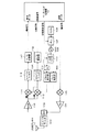
図1には、本発明を適用することが可能な、UWB無線通信装置10の構成を模式的に示している。同図に示すように、UWB無線通信装置10は、インパルス信号の送受信を行なうUWBアンテナ11と、伝送信号の変復調処理を行なうUWB RF処理部12と、ベースバンド信号の変復調処理、同期処理、伝搬路測定、並びに測距を行なうUWBベースバンド処理部13と、アクセス制御や伝送レートの適応制御を行なうUWB MAC(Media Access Control)層処理部14と、隣接ノード管理や暗号化、認証処理などを行なうUWB DLC(Data Link Control)層処理部15とで構成される。このうち、UWBアンテナ11と、UWB RF処理部12と、UWBベースバンド処理部13は、UWB物理層に相当する。
【0038】
図2には、UWB RF処理部12の内部構成をより詳細に示している。また、図3には、UWBベースバンド処理部13の内部構成を示している。但し、図示の例では、BPSK(Binary Phase Shift Keying)変調方式を適用しており、I軸にのみで送信データが搬送される。
【0039】
まず、送信動作について説明する。送信データは、ベースバンド回路13内で乗算器153により拡散コードと乗算(変調)されて拡散送信データを得る。また、水晶発振器(TCXO)108などから出力される発振周波数をPLL107及びVCO106を用いて逓倍してより高い発振周波数を得る。パルス発生器109はこの発振周波数を用いてパルス信号を生成する。そして、PN拡散された送信信号を所定のパルス幅のパルス信号で乗算器105により変調(乗算)し、インパルス信号列となった送信信号をパワー・アンプ(PA)104で増幅し、バンドパス・フィルタ(BPF)102でFCCなどの規制に適合する周波数の信号成分だけを取り出し、アンテナ101から伝送路に送出する。
【0040】
一方、受信時には、アンテナ101で受信された信号は、バンドパス・フィルタ102を通過して送信パルス信号成分以外の周波数成分が除去される。バンドパス・フィルタ102を通過した信号はさらに低雑音アンプ110によって増幅される。また、水晶発振器(TCXO)108から出力される発振周波数をPLL107及びVCO106を用いて逓倍して、送信時と同じ周波数を用いてパルス発生器109によるテンプレート・パルスを得るとともに、他方のパルス発生器112では直交変調器111により90degだけ位相のずれたテンプレート・パルスを得る。これらを各乗算器113及び114において受信信号とそれぞれ乗算して、I軸及びQ軸それぞれの検波信号を得る。さらに、これら検波信号をそれぞれローパス・フィルタ(LPF)115及び116にかけて高周波成分を除去し、そのフィルタ後のパルスのピークにおいて各A/D変換117及び118においてデジタル信号に変換処理し、後はUWBベースバンド処理部13内でデジタル処理を行なう。
【0041】
UWBベースバンド処理部13内では、I軸及びQ軸の各検波信号にはそれぞれ拡散コードが乗算器151及び152によりそれぞれ乗算され逆拡散が行なわれ、積分ダンプ154及び155において逆拡散信号を積分する。I軸信号に関しては、FEC(Forward Error Correction)156並びにCRC(Cyclic Redundancy Check Code)157が施され、受信データが取り出される。また、Q軸信号に関しては、ループ・フィルタ158を介してクロック発生器に帰還される。クロック発生器では、積分出力に従ってクロック発生タイミングを調整する。
【0042】
また、本実施形態に係るUWBベースバンド処理部13は、情報伝送を行なう毎に無線機間の測距を行なう測距機能を備えている。より具体的には、カウンタ161を有し、通常の通信シーケンスにおいて通信相手となる無線機にパケットを送信し、この通信相手がパケット検出時から単位時間の整数倍の時間経過後に必ず返送されるパケットを返送されるタイミング付近のみパケット検出処理を行ない、自身がパケットを送信してから返信パケットを検出するまでの時間をカウンタ161で計測し、通信相手のパケット検出から送信までの時間を決定し、その決定した時間と自身の処理時間を計測時間から差し引いた時間を通信相手との伝搬距離に換算することで測距を行なう。
【0043】
パケット検出処理では、例えば、受信データの積分ダンプ154と拡散コードとの相関値を相関検出器162によって検出し、最大且つ所定の相関値以上となった位置をカウンタ161で計数し、これをタイミング信号計測時間データとして得る。相関検出器162の前に拡散コードが乗算されているので、相関検出器162はI軸、Q軸の各出力により拡散符号との相関の有無を調べることができる。なお、送受信とも拡散符号の制御信号がカウンタ161に入っているのは、送信側の拡散符号のスタートから受信側の拡散符号が同期するまでをカウントできるように意図したものである。
【0044】
なお、本実施形態では、同期獲得のために、位相シフタ回路119を用い、発生タイミングをシフトさせることによりスライディング相関を行なうようになっている。このようなスライディング相関の手法については、例えば本出願人に既に譲渡されている特願2003−27541号明細書に記載されている。但し、同期獲得の方法自体は本発明の要旨に直接関連しないので、ここではこれ以上説明しない。
【0045】
本発明に係る無線通信システムでは、情報伝送を行なう毎に無線機間の測距を行なう。通常の通信シーケンスにおいて、ある無線機1が通信相手である無線機2にパケットを送信したとき、無線機2側では、パケットを受信した後、パケット検出時から単位時間の整数倍の時間経過後に必ずパケットを送信するようにする。そして、無線機1は、自身が送信してから無線機2からパケットが返送されるタイミング付近のみパケット検出処理を行ない、自身がパケットを送信してから無線機2のパケットを検出するまでの時間をカウンタで計測し、無線機2のパケット検出から送信までの時間を決定する。ここで決定した時間と無線機1自身の処理時間を計測時間から差し引いた時間を、通信相手である無線機2との伝搬距離に換算することで測距を実現する。
【0046】
2つの無線機が無線機同士の信号の送受信により無線機同士の測距を行なう仕組みについて、図4を参照しながら説明する。
【0047】
無線機1は、無線機2に向けてパケット▲1▼を送った後、無線機2からパケット▲2▼が返送されるまで待機する。そして、無線機1は、パケット▲1▼の送信からパケット▲2▼が検出されるまでの時間を自身のカウンタ161で計測する。
【0048】
無線機2は、無線機1からのパケット▲1▼を受信し検出すると、所定の時間後(単位時間の整数倍の経過後:後述)にパケット▲2▼を無線機1に返送する。
【0049】
無線機1は、返送されたパケット▲2▼を検出し、検出時のカウンタ値から無線機1から無線機2までの距離を計算する。図示の時間はロジック回路が認識する時間とする。
【0050】

通常、無線機2の処理時間は信号検出に要する処理時間とRF送受信回路の各遅延時間は固定値である。上記の定義により、tは以下のように表される。
【0052】
また、無線機間の距離dは下式の通りとなる。
【0054】
d=c・tAIR(cは光速) …(2)
【0055】
したがって、無線機1は、時間tをカウントし、上式からtAIRを計算することにより無線送信機間の距離dを得ることができる。UWBのような超広帯域信号では、受信パルス検出又は相関検出において高い時間分解能が得られるので、例えば1ナノ秒の時間分解能であれば、無線通信システムとしての距離分解能は30cmとなる。
【0056】
このようにして、無線機間の距離を相互の通信により計測することができる。但し、無線ネットワークを構成する一方の無線機2の処理時間tP2には、IFS(Inter Flame Space)やパケットの衝突確率を下げるためのランダムな遅延時間のような時間間隔なども含まれる。このような場合に、無線機2のtP2(若しくはtB)は固定値でないので、無線機1は何らかの方法、例えば無線機2が返送するパケットに処理時間tP2に関する情報を乗せるなどの方法によりtP2を知る必要がある。ところが、測距するために特別な情報をパケットに加えるのは帯域の有効利用の観点から好ましくない。
【0057】
本実施形態では、IFSやランダムな遅延時間などを含めた無線機2の処理時間tP2(若しくはtB)を必ず特定の単位時間の整数倍、例えば100ナノ秒×Nとなるようにした。但し、Nは整数であることのみが通信システム内で約束されているだけで、その値は不定である。このような場合、無線機1側では、自身がパケットを送信した後、単位時間の整数倍後のパケットが返送される可能性のあるタイミング付近でのみパケット検出処理を繰り返し行なう。パケット検出処理では、例えば拡散コードとの相関値が検出され、最大且つ所定の相関値以上となった位置を計測結果とする。
【0058】
例えば、無線機2の処理時間tP2(若しくはtB)を単位時間としての100ナノ秒に設定すると、単位時間分の信号の伝送距離はこれに高速cを掛けた30mとなる。したがって、単位時間のN倍の遅延時間でパケットが返送されることが約束されているだけで、Nの値は不定であることから、この単位時間分の距離30mの倍数がパケット検出処理時の不定分として生ずる。一方、通常の高速伝送では通信可能な距離には限界があるので、例えば30m以下の通信可能な距離の通信システムの場合、測距する範囲を30m以内に限定すれば、この不定性はまったく問題とならないことになる。
【0059】
したがって、無線機1は上式(2)で得た距離を30mで割った余りを無線機1〜2間の距離として特定することができる。これは、Nの値を特定してtから100ナノ秒×Nを差し引いてから上式(2)を計算することと等価である。
【0060】
図5には、拡散コードとの相関をとることによりパケット検出処理を行なった例を示している。無線機1では、パケットを送信した後、無線機2の処理時間tP2(若しくはtB)100ナノ秒×Nが経過してから返送パケットの受信処理を開始し(又は、パケット送信後から100ナノ秒の整数倍の経過時間を無視する)、受信信号と拡散コードとの相関を検出する。そして、さらにtA+tCが経過した後に、最大且つ所定の相関値以上となった相関ピーク位置が検出されるので、これを計測結果とする。
【0061】
本実施形態では、一般にはパケット交換における余計な時間とされる無線機2の処理時間tP2(若しくはtB)を有効に活用することによって、無線機がパケットを受信してから返送するまでの時間を固定とせず、また、測距するために特別な情報をパケットに加えることなく、パケットを送受信する2つの無線通信機間で測距・測位を実現することができる、という訳である。
【0062】
このような方法では、測距を行なう無線機1は、無線システムで取り決められている単位時間間隔(上記の例では100ナノ秒)だけ知っていればよく、無線機2からのtP2に関する情報を直接知る必要はない。また、無線機1は、無線機間でパケットの送受信を行ないながら毎回測距を行なうことにより、測距情報を逐次更新することができる。これは、例えば無線機が移動している場合のナビゲーションや自律ロボットの制御などの用途において有効である。
【0063】
パケットの検出には信号強度や伝搬特性によって誤検出の可能性があるため、誤検出の際には誤った測距結果を出す。このような場合のため、無線機は、データの信憑性のあるときのみ測距を行なうようにすればよい。
【0064】
より具体的には、相関検出結果だけでなく、無線機間距離に依存する信号検出強度と比較して矛盾がないか、また、図1に示した無線機の構成例におけるUWB MAC層処理部14でCRCなどのチェックを行ない、検出したパケットの正当性を判断してから距離を計算するか、又は計算した距離を利用することで測距結果の誤りによるトラブルを防止することができる。
【0065】
また、一般的な無線通信動作において、測距情報は必ずしも毎回必要ではない。したがって、図1に示したUWB無線機の構成例において、前段のRF処理部12及びベースバンド処理部13までの機能モジュールでは、パケットを検出する部分では誤検出の可能性を伴いながらも、常時測距データを更新する仕組みとし、後段のMAC層処理部14やDLC層処理部15などの上位側では必要なときのみに測距の計測結果を読み出し、距離換算するように構成してもよい。
【0066】
このようにして得られる測距情報は、無線機自身の制御に利用することができる。例えば、パケットの通信を行なっている相手の距離に応じて送信電力を制御すると、他の無線機への干渉を低減することができる。
【0067】
また、無線機の利用者が対象機器に接近したとき、すなわち距離が所定の値のときだけ確実に行ないたい処理を起動するようにすることができる。例えば、対象機器から50cm以内に接近したことに応答して、例えば、NFCや高いセキュリティが要求される機器購入時の最初の利用コード登録などに、測距の結果を応用することができる。この場合、送信電力を下げるだけでなく、伝送速度を故意に上げることでも通信可能な範囲を限定することができる。
【0068】
また、無線ネットワークでは、各無線機は他の無線機が発するビーコンを受信することで周囲に存在する無線機を認識することができる。さらに、ビーコンを受信できた無線機のリストを各無線機において記憶領域に保持することができる。本発明によれば、各無線機がビーコンを受信するだけでなく、無線機間で互いにパケットの送受信を適宜行なうことで測距するようにすることで、単に周囲に存在する無線機を認識するだけでなく、認識した各無線機との距離を関連付けて記憶し、さらに測距する毎に周囲の無線機との測距情報を更新することができる。
【0069】
周辺に存在する無線機とその測距情報だけであれば、他の無線機同士の位置関係までは把握できない。これに対し、無線機が他の無線機の保持するリストと測距情報を通信により獲得することで、周囲に存在する位置関係を導出することができる。
【0070】
例えば、ある無線機の周囲に2つの無線機がある場合に、少なくとも一方の無線機が保持するリストと測距情報を獲得するようする。無線機は、自身の保持するリスト及び測距情報とすり合わせることで、これら3つの無線機の位置を頂点とする3角形が一意に求めることができ、近隣の無線機相互の相対的な位置関係を把握することができる。また、他方の無線機の保持するリストと測距情報を獲得することができれば、相互の位置関係の信頼性を高めることができる。
【0071】
図6には、周囲の無線機から無線機のリストと測距情報を獲得し、自身の保持するリスト及び測距情報とすり合わせて、近隣の無線機相互の相対的な位置関係を把握する様子を示している。同図に示す例では、無線機1〜3が互いの通信可能範囲に存在している。無線機1は、無線機2との距離が6mで、無線機3との距離が10mであるというリストと測距情報を自身で保持している。また、無線機2は、無線機1との距離が6mで、無線機3との距離が8mであるというリストと測距情報を自身で保持している。ここで、無線機1は、無線機2から無線機のリストと測距情報を獲得し、自身が保持している情報とすり合わせることによって、図示の通り、3つの無線機1〜3の位置を頂点とする3角形が一意に求められ、無線機相互の相対的な位置関係を把握することができる。
【0072】
この方法は、4つ以上の無線機が存在する場合にも、複数の3角形の組み合わせにより拡張することができる。
【0073】
また、上述したように各無線機の相対位置を把握することができれば、直接信号が届かないような無線機同士の通信において、マルチホップ伝送のルート決定に利用することができる。
【0074】
図7には、無線機間の相対位置は悪に基づくマルチホップ伝送のルート決定を行なう様子を示している。図示の例では、無線機3から無線機4に信号を送りたいが、これらは直接信号が届かない場所に存在している。周囲の無線機から無線機のリストと測距情報を獲得し合うことにより、無線機3は、無線機5の通信可能範囲に送信先の無線機4が存在することを把握できる。そこで、無線機3から無線機4への伝送を、無線機5を介して行なうというマルチホップ伝送のルートが決定される。
【0075】
また、無線機を有する機器の中には、位置がほぼ固定で動くことがほとんどないものがある。例えば、大型テレビやオーディオ機器、デスクトップPC(Personal Computer)などに無線機を組み込む場合がこれに該当する。これらの機器には位置が固定であるという情報を付加することで、無線機は位置固定の無線機を基点とした位置関係を導出することができる。
【0076】
例えば、図6で示した例で、無線機2と無線機3が位置固定であるとする。そして、無線機1が、無線機のリストと測距情報に加えて、各無線機が一固定かどうかを示す情報を獲得している場合、無線機2をX−Y座標の原点(0,0,0)とし、無線機3を(0,8m,0)と設定することで、無線機1は無線機2を原点とし、無線機2と無線機3を結ぶ直線をY軸とする座標系で位置を表すことができる。
【0077】
また、3個以上の無線機又は無線機を有する機器が無線機の存在する空間の見取り図や地図情報を外部から入手することができ、固定されている無線機の位置情報と結合すると、各無線機は自位置又は他の無線機の位置を導出し、無線機の位置を見取り図や地図情報にマッピングすることができる。これは室内における位置認識システムなどに応用できる。
【0078】
以上説明してきたように、無線機間でパケットの送受信による測距は無線システムに付加価値をもたらすことができる。但し、測距の基本となる式(1)、並びに式(2)は、無線機に搭載された発振器によるクロック周波数の精度に起因する誤差を考慮していない。
【0079】
図4に示したようなパケット送受信動作を行なう無線機1、並びに無線機2の処理時間には自身のクロックの精度に起因する誤差が含まれている。ここで、処理時間tP1、tP2の公称値をそれぞれtP1’、tP2’とし、無線機1及び無線機2のクロックの誤差(比)をそれぞれε1、ε2とする。ここで言う処理時間の公称値は、処理に要する正確なクロック数をクロック周波数の公称値により換算した時間を意味する。例えば、TCXO(Temperature Compensated Crystal Oscilator:温度補償型水晶発振器)の誤差が10ppm以内であるならば、|ε| < 10×10−6である。この定義により、無線機1がパケットを送出してから無線機2のパケットを検出するまでの真の時間tは下式で表わされる。
【0080】
t=2tAIR+tD1+tD2+tP1’(1+ε1)+tP2’(1+ε2) …(3)
【0081】
無線機1は真の時間tを自身のクロックでカウントするが、そのカウント値に基づく計測時間をtCNTとすると、t=tCNT・(1+ε1)である。但し、ここではクロックの分解能による量子化誤差は考慮しない。以上により、無線機1と無線機2間の距離dは以下のように表わされる。
【0082】
実際の距離計算において、RF送受信回路の遅延時間tD1、tD2とクロックの誤差ε1、ε2を考慮しない最も簡易な距離計算を行なう場合(すなわち、ε1、ε2=0として計算)、正確な距離に対して下式に示すような誤差Δdを生ずる。
【0084】
Δd={(tCNT−tP1’)ε1−tP2’ε2−(tD1+tD2)}c/2 …(5)
【0085】
最も簡易な距離計算による結果には、上式(5)が示すように、RF送受信回路の遅延時間とクロック精度に起因する誤差を生ずる。RF送受信回路12の遅延時間については、せいぜい分解能程度の誤差か、または分解能程度の精度でわかると考えられる。tP1’は十分小さいと思われるので、クロック精度の影響はtP2’が支配的になる。
【0086】
例えば、tP2’を100マイクロ秒、ε1、ε2を10ppmとした場合、上式(5)より誤差は最大30cm程度となる。tP2’が小さい場合には充分な測距精度となる。tP2’が大きくなると、ほぼ比例して誤差は大きくなる。
【0087】
また、上述の説明では、上式(5)が無線機1、並びに無線機2の処理時間の公称値tP1’、tP2’が正しいことを前提としているということに留意されたい。これらの公称値自体が誤っている(設計者によるクロック数見積もりのミス)と、大きな誤差の要因となる。例えば、tP2’に10ナノ秒分のミスカウント(クロックが100MHzであれば1クロック分)があった場合、上式(4)より3mほど誤差が生ずる。但し、ミスカウントの最小単位が10ナノ秒であれば誤差は3mの倍数となるので、受信時の信号強度又はS/Nと合わせて判断することで補正できる可能性がある。
【0088】
パケットの送受信を2回だけ行ない、2回の結果から測距の誤差を減らすことができる。無線機2で処理時間tP2’を故意に変えて、2回tCNTを測ると、上式(5)の誤差Δdを小さくし、測距の精度を改善することができる。
【0089】
例えば、無線機1、及び無線機2が図4に示したようなパケットの送受信処理を2回続けて行なう場合に、無線機2は1回目と2回目で処理時間tP2を故意に変える。1回目の処理時間tP2’に対し、2回目をtP2’のk倍(但し、kは正の実数)とすれば、無線機1の1回目、及び2回目の時間計測値tCNT1、tCNT2はそれぞれ下式のように表わされる。
【0090】
上記の2式からtP2’の項を消去することにより、無線機1、無線機2間の距離dは下式のように求められる。
【0092】
d=c・tAIR=[{(ktCNT1−tCNT2)/(k−1)−tP1’}(1+ε1) −(tD1+tD2)]c/2 …(7)
【0093】
この方法によれば、上式(7)が示すように、無線機2のクロック精度による誤差要因を除くことができ、測距精度が改善される。特に、無線機1のクロックの精度が高い場合に効果が大きい。但し、kに誤差がない(すなわち、クロック数のミスカウントがない)ことが前提である。k → k(1+εk) のように誤差があると、以下のような距離誤差Δdを生ずる。
【0094】
Δd=εktP2’(1+ε2)c/2≒εktP2’c/2 …(8)
【0095】
測距を行なう場合におけるtP1’並びにtP2’のクロック数のミスカウントによる公称値からのずれは、そのまま測距の誤差となり、クロック周波数の精度以上に大きくなる可能性が高い。したがって、tP1’、tP2’には正確さが要求される。
【0096】
クロック周波数の精度が高く、tP1’にも誤差のないリファレンスとなる無線機を用意し、そのリファレンスを無線機1とし、無線機1並びに無線機2を例えば正確に1m離して測距を行なわせ、上式(1)及び(2)により計算される距離dと真の距離1mの差の2倍を光速cで割ることで、tP2’における誤差を知り、補正することができる。このような補正作業を、例えば量産時の工程で必ず行ない、前記方法で得た補正値を無線機の記憶領域に保持するようにすれば、処理時間tP2’の公称値からのずれの問題を解消することができる。
【0097】
また、処理時間tP2’の公称値からのずれがないことが保証されている場合には、リファレンスの受信機のクロックを高精度(ε1がε2に比べてかなり小さい)にしておくことで、上式(1)及び(2)により計算される距離dと真の距離1mの差をΔdとすることで、上式(5)から無線機2のクロック周波数の誤差ε2を計算することができ、補正用に保持しておくことも可能である。
【0098】
[追補]
以上、特定の実施形態を参照しながら、本発明について詳解してきた。しかしながら、本発明の要旨を逸脱しない範囲で当業者が該実施形態の修正や代用を成し得ることは自明である。すなわち、例示という形態で本発明を開示してきたのであり、本明細書の記載内容を限定的に解釈するべきではない。本発明の要旨を判断するためには、冒頭に記載した特許請求の範囲の欄を参酌すべきである。
【0099】
【発明の効果】
以上詳記したように、本発明によれば、電波を利用して物体間の相対的な距離を好適に測定することができる、優れた測距・測位システム及び測距・測位方法、並びに無線通信装置を提供することができる。
【0100】
また、本発明によれば、パケットを送受信する2つの無線通信機間で好適に測距・測位することができる、優れた測距・測位システム及び測距・測位方法、並びに無線通信装置を提供することができる。
【0101】
また、本発明によれば、無線機がパケットを受信してから返送するまでの時間を固定とせず、また、測距するために特別な情報をパケットに加えることなく、パケットを送受信する2つの無線通信機間で好適に測距・測位することができる、優れた測距・測位システム及び測距・測位方法、並びに無線通信装置を提供することができる。
【0102】
本発明に係る無線通信システムによれば、情報伝送を行なう毎に無線機間の測距を行なうことができ、逐次測距情報を更新することができる。
【0103】
また、相手の無線機がパケット検出から返送までの時間を固定値としない柔軟な無線ネットワークにおいても、相手の無線機の時間情報をもらうことなく測距することができる。
【0104】
また、測距で得られる情報を利用して無線機あるいは無線ネットワークの制御や無線機を有する機器の機能を制限することができる。
【0105】
また、本発明を逐次更新される無線機の位置情報を利用した位置認識システムなどへ応用することができる。
【図面の簡単な説明】
【図1】本発明を適用することが可能な、UWB無線通信装置10の構成を模式的に示した図である。
【図2】UWB RF処理部12の内部構成をより詳細に示した図である。
【図3】UWBベースバンド処理部13の内部構成を示した図である。
【図4】2つの無線機が無線機同士の信号の送受信により無線機同士の測距を行なう仕組みを説明するための図である。
【図5】拡散コードとの相関をとることによりパケット検出処理を行なった例を示した図である。
【図6】周囲の無線機から無線機のリストと測距情報を獲得し、自身の保持するリスト及び測距情報とすり合わせて、近隣の無線機相互の相対的な位置関係を把握する様子を示した図である。
【図7】無線機間の相対位置は悪に基づくマルチホップ伝送のルート決定を説明するための図である。
【符号の説明】
10…UWB無線通信装置
11…UWBアンテナ
12…UWB RF処理部
13…UWBベースバンド処理部
14…UWB MAC層処理部
15…UWB DLC層処理部
102…バンドパス・フィルタ(BPF)
103…分波器(SW)
104…パワー・アンプ(PA)
105…乗算器
106…VCO
107…PLL
108…TCXO
109…パルス発生器
110…低雑音アンプ(LNA)
111…直交変調器
112…パルス発生器
115,116…ローパス・フィルタ
117,118…A/D変換器
119…位相シフタ回路
151,152,153…乗算器
154,155…積分ダンプ
156…FEC
157…CRC
158…ループ・フィルタ
159…同期獲得用論理回路
161…カウンタ
162…相関検出器[0001]
TECHNICAL FIELD OF THE INVENTION
The present invention relates to a distance measurement / positioning system and a distance measurement / positioning method for measuring a relative distance between two objects and a distance measurement / positioning method, and a wireless communication device. The present invention relates to a distance measuring / positioning system and a distance measuring / positioning method for measuring a relative distance, and a wireless communication device.
[0002]
More specifically, the present invention relates to a distance measuring / positioning system and a distance measuring / positioning method for measuring a relative distance between two wireless communication devices that transmit and receive a packet, and a wireless communication device. TECHNICAL FIELD The present invention relates to a distance measurement / positioning system and a distance measurement / positioning method for performing distance measurement / positioning using a packet transmission and response procedure therebetween, and a wireless communication device.
[0003]
[Prior art]
Systems for distance measurement and positioning using radio waves have been around for quite some time, for example, as represented by radar using reflection and radio navigation systems using a plurality of reference stations.
[0004]
In Loran or GPS (Global Positioning System), by strictly synchronizing a plurality of reference stations, a wireless device can perform positioning only by receiving.
[0005]
In addition to Loran and GPS, there are a method of positioning using radio waves from a base station of a mobile phone (for example, see Patent Document 1), a positioning method using TV radio waves, and the like (for example, non-patented).
[0006]
In the inter-vehicle communication in the ITS, a distance measurement method called a “boomerang method” is used to measure an inter-vehicle distance. This means that the radios do not need to be synchronized. As an example, there is a type in which the signal to be measured multiplies the signal itself from the wireless device for distance measurement itself and sends it back, and the wireless device for distance measurement performs distance measurement by measuring the round-trip radio wave propagation time. .
[0007]
In the above method, the distance measuring side simply sends back the received signal with little reception signal processing. However, there is also a method in which the distance measuring side measures the distance from the time from the transmission including the signal processing time of itself and the distance measurement side to the reception of the return signal on the distance measurement side (for example, see Patent Document 3).
[0008]
In recent years, a method called “ultra-wide band (UWB) communication” for performing wireless communication by carrying information on an extremely weak impulse train has attracted attention as a wireless communication system that realizes short-distance ultra-high-speed transmission, and has been put to practical use. Is expected (for example, see Non-Patent Document 2).
[0009]
In the UWB transmission system, an information signal is formed by using a DS-UWB system in which the spreading speed of a DS information signal is extremely high and an impulse signal train having a very short period of about several hundred picoseconds. There are two types of impulse-UWB system for transmitting and receiving columns. Both systems achieve high-speed data transmission by performing transmission and reception by spreading over an ultra-high frequency band of, for example, 3 GHz to 10 GHz. The occupied bandwidth is a band on the order of GHz such that a value obtained by dividing the occupied bandwidth by its center frequency (for example, 1 GHz to 10 GHz) is substantially 1, and is a so-called W-CDMA or cdma2000 system, and an SS (Spread Spectrum). ) Or an OFDM (Orthogonal Frequency Division Multiplexing) scheme, which is an ultra-wide band compared to a bandwidth normally used in a wireless LAN.
[0010]
UWB communication has a high time resolution by using ultra-fine pulses, and by using this property, it is possible to perform "ranging" for radar and positioning. In particular, recent UWB communication can have both high-speed data transmission exceeding 100 Mbps and the original distance measurement function.
[0011]
In the future, it is expected that WPAN (Wireless Personal Access Network) for short-distance communication represented by UWB will be mounted on all home appliances and CE (Consumer Electronics) devices. Therefore, apart from high-speed data transmission, it is conceivable that the use of position information by distance measurement, for example, an added value of wireless such as navigation and near field communication (Near Field Communication: NFC) may be provided. It is also considered desirable to implement.
[0012]
As described above, distance measurement is generally performed from the time from packet transmission to reception. However, setting the time from when the wireless device receives a packet to when it returns the packet to a fixed value is inconvenient in a system in which the processing content changes depending on the length and type of the packet. Also, it is not preferable to add special information to the packet for distance measurement from the viewpoint of effective use of the bandwidth.
[0013]
[Patent Document 1]
JP-A-10-257545
[Patent Document 2]
JP-A-5-119145
[Patent Document 3]
JP-A-8-62334
[Non-patent document 1]
http: // www / rosum. com
[Non-patent document 2]
Nikkei Electronics, March 11, 2002, “Wireless Revolutionary Ultra Wideband” 55-66
[0014]
[Problems to be solved by the invention]
An object of the present invention is to provide an excellent distance measurement / positioning system, an excellent distance measurement / positioning method, and a wireless communication device capable of suitably measuring a relative distance between objects using radio waves. is there.
[0015]
A further object of the present invention is to provide an excellent distance measurement / positioning system, an excellent distance measurement / positioning method, and a wireless communication device capable of suitably performing distance measurement / positioning between two wireless communication devices that transmit and receive packets. It is in.
[0016]
A further object of the present invention is to provide an excellent distance measurement / positioning system and a distance measurement / positioning method, which can perform distance measurement / positioning using a packet transmission between a source and a destination and a response procedure thereof, and A wireless communication device is provided.
[0017]
It is a further object of the present invention to provide a method for transmitting and receiving a packet without using a fixed time from when a wireless device receives a packet to returning it, and without adding special information to the packet for distance measurement. An object of the present invention is to provide an excellent distance measurement / positioning system, an excellent distance measurement / positioning method, and a wireless communication device that can perform distance measurement / positioning suitably between communication devices.
[0018]
Means and Action for Solving the Problems
The present invention has been made in view of the above problems, and is a ranging / positioning system that measures and locates between two wireless devices that transmit and receive packets,
Transmit the packet from the source radio,
At the transmission destination radio, the packet is returned after a time corresponding to an integral multiple of a predetermined unit time has elapsed since the packet was received,
In the transmission source radio, an integral multiple of a predetermined unit time is removed from the required time from the transmission of a packet to the reception of a return packet to determine the round-trip transmission time of the packet, and based on the round-trip transmission time, Measuring the distance between the source and destination radios,
This is a distance measurement / positioning system characterized by the following.
[0019]
However, the term “system” as used herein refers to a logical collection of a plurality of devices (or functional modules that realize specific functions), and each device or functional module is in a single housing. It does not matter in particular.
[0020]
In the distance measuring / positioning system according to the present invention, each time information is transmitted between two wireless communication devices that transmit and receive a packet, the distance between wireless devices is measured.
[0021]
When a transmission source radio device transmits a packet to a transmission destination radio device, the transmission destination always transmits a packet after receiving the packet and after a lapse of an integral multiple of a unit time from the detection of the packet.
[0022]
Then, the transmitting wireless device performs the packet detection process only near the timing at which the packet is returned from the destination after transmitting the wireless device, and performs processing from the time when the
[0023]
According to the present invention, two wireless communication systems for transmitting and receiving packets without fixing the time from when a wireless device receives a packet to returning the packet and without adding special information to the packet for distance measurement. Distance measurement and positioning can be suitably performed between the devices.
[0024]
Further, according to the present invention, it is possible to perform distance measurement between wireless devices each time information transmission is performed, and it is possible to sequentially update distance measurement information.
[0025]
In packet detection, there is a possibility of erroneous detection depending on the signal strength and propagation characteristics. In the case of erroneous detection, there is a possibility that an erroneous distance measurement result will be output. For this reason, the wireless device may measure the distance only when the data is authentic.
[0026]
Further, according to the ranging / positioning system according to the present invention, it can be used for control of the wireless device itself based on the ranging information. For example, if the transmission power is controlled in accordance with the distance of the other party communicating the packet, interference with other wireless devices can be reduced.
[0027]
Further, according to the distance measuring / positioning system according to the present invention, it is possible to control or limit the function of the wireless device or the device including the wireless device based on the result of the distance measurement.
[0028]
For example, when the user of the wireless device approaches the target device, that is, when the distance is a predetermined value, it is possible to activate a process that the user wants to perform reliably. In addition, in response to approaching within 50 cm from the target device, the result of the distance measurement can be applied to the first use code registration at the time of purchase of a device requiring NFC or high security. In this case, the range in which communication is possible can be limited by not only lowering the transmission power but also intentionally increasing the transmission speed.
[0029]
Further, according to the ranging / positioning system according to the present invention, the wireless device acquires the list and the ranging information held by the other wireless devices through communication, thereby deriving the positional relationship existing around the wireless device. .
[0030]
For example, when there are two wireless devices around a certain wireless device, a list and ranging information held by at least one of the wireless devices are acquired. The wireless device can uniquely obtain a triangle having the positions of these three wireless devices as vertices by reconciling the list and the ranging information held by the wireless device, and the relative positions of the wireless devices in the vicinity are determined. You can understand the relationship. Further, if the list and the ranging information held by the other wireless device can be obtained, the reliability of the mutual positional relationship can be improved.
[0031]
In addition, the position information of two or more radios whose positions are fixed is combined with other position information such as a map or map information, so that each radio has its own position or other position information based on the other two or more position information. Can be derived and mapped.
[0032]
According to the ranging / positioning system according to the present invention, in the communication between the wireless devices, the communication is performed twice while changing the time until the wireless device of the transmission destination returns the packet, and the wireless device of the transmission source performs the communication twice. From the measurement result, the error caused by the measurement accuracy of the transmission destination wireless device for a predetermined time can be canceled.
[0033]
In addition, the antennas of two or more radios are arranged in a predetermined positional relationship, and the radios correct their actual error and the nominal value of the time from packet detection to transmission based on the result of distance measurement for a known relative distance. be able to. Alternatively, the antennas of two or more radios can be arranged in a predetermined positional relationship, and the radio can correct its own oscillator error based on the distance measurement result for a known relative distance.
[0034]
Further objects, features, and advantages of the present invention will become apparent from more detailed descriptions based on embodiments of the present invention described below and the accompanying drawings.
[0035]
BEST MODE FOR CARRYING OUT THE INVENTION
Hereinafter, embodiments of the present invention will be described in detail with reference to the drawings.
[0036]
The wireless communication system according to the present invention employs the UWB transmission method (described above) in which information is carried on a weak impulse train to perform wireless communication. However, information transmission is performed by utilizing a high time resolution by using ultra-fine pulses. Is configured to measure the distance between the wireless devices each time is performed.
[0037]
FIG. 1 schematically shows a configuration of a UWB wireless communication device 10 to which the present invention can be applied. As shown in FIG. 1, the UWB wireless communication apparatus 10 includes a
[0038]
FIG. 2 shows the internal configuration of the UWB
[0039]
First, the transmission operation will be described. The transmission data is multiplied (modulated) with a spreading code by a
[0040]
On the other hand, at the time of reception, the signal received by the antenna 101 passes through the band-
[0041]
In the UWB
[0042]
In addition, the UWB
[0043]
In the packet detection process, for example, a correlation value between the
[0044]
In the present embodiment, for obtaining synchronization, the
[0045]
In the wireless communication system according to the present invention, the distance between wireless devices is measured each time information is transmitted. In a normal communication sequence, when a
[0046]
A mechanism in which two wireless devices measure the distance between the wireless devices by transmitting and receiving signals between the wireless devices will be described with reference to FIG.
[0047]
After transmitting the packet (1) to the
[0048]
Upon receiving and detecting the packet (1) from the
[0049]
The
[0050]
Normally, the processing time of the
[0052]
The distance d between the wireless devices is as follows.
[0054]
d = ct AIR (C is the speed of light) ... (2)
[0055]
Therefore, the
[0056]
In this way, the distance between wireless devices can be measured by mutual communication. However, the processing time t of one
[0057]
In the present embodiment, the processing time t of the
[0058]
For example, the processing time t of the wireless device 2 P2 (Or t B ) Is set to 100 nanoseconds as a unit time, the transmission distance of the signal for the unit time is 30 m obtained by multiplying this by the high speed c. Therefore, it is only promised that a packet is returned with a delay time N times the unit time, and the value of N is undefined. Occurs as indefinite. On the other hand, in normal high-speed transmission, the communicable distance is limited. For example, in the case of a communication system with a communicable distance of 30 m or less, if the range to be measured is limited to 30 m or less, this indefiniteness is a problem. It will not be.
[0059]
Therefore, the
[0060]
FIG. 5 shows an example in which a packet detection process is performed by correlating with a spreading code. In the
[0061]
In this embodiment, the processing time t of the
[0062]
In such a method, the
[0063]
In packet detection, there is a possibility of erroneous detection depending on the signal strength and propagation characteristics. Therefore, in the case of erroneous detection, an erroneous distance measurement result is output. For such a case, the wireless device may measure the distance only when the data is credible.
[0064]
More specifically, whether there is no inconsistency in comparison with not only the correlation detection result but also the signal detection strength depending on the distance between wireless devices, and whether the UWB MAC layer processing unit in the configuration example of the wireless device shown in FIG. A check such as CRC is performed at 14 and the distance is calculated after judging the validity of the detected packet, or a trouble due to an error in the distance measurement result can be prevented by using the calculated distance.
[0065]
In a general wireless communication operation, distance measurement information is not always necessary. Therefore, in the configuration example of the UWB wireless device shown in FIG. 1, in the functional modules up to the
[0066]
The distance measurement information thus obtained can be used for control of the wireless device itself. For example, if the transmission power is controlled in accordance with the distance of the other party communicating the packet, interference with other wireless devices can be reduced.
[0067]
Further, when the user of the wireless device approaches the target device, that is, only when the distance is a predetermined value, it is possible to activate a process that the user wants to perform reliably. For example, in response to approaching within 50 cm from the target device, the result of distance measurement can be applied to, for example, the first use code registration at the time of purchase of a device requiring NFC or high security. In this case, the range in which communication is possible can be limited by not only lowering the transmission power but also intentionally increasing the transmission speed.
[0068]
In a wireless network, each wireless device can recognize a wireless device existing in the vicinity by receiving a beacon issued by another wireless device. Further, a list of wireless devices that can receive the beacon can be stored in a storage area in each wireless device. According to the present invention, each wireless device not only receives a beacon, but also transmits and receives packets to and from each other as appropriate, thereby performing distance measurement, thereby simply recognizing a wireless device existing in the vicinity. In addition, the distance to each recognized wireless device is stored in association with each other, and each time the distance is measured, the distance measurement information to the surrounding wireless devices can be updated.
[0069]
If there is only a wireless device existing in the vicinity and its ranging information, the positional relationship between other wireless devices cannot be grasped. On the other hand, the wireless device acquires the list and the distance measurement information held by the other wireless devices through communication, so that the positional relationship existing around the wireless device can be derived.
[0070]
For example, when there are two wireless devices around a certain wireless device, a list and ranging information held by at least one of the wireless devices are acquired. The wireless device can uniquely obtain a triangle having the positions of these three wireless devices as vertices by reconciling the list and the ranging information held by the wireless device, and the relative positions of the wireless devices in the vicinity are determined. You can understand the relationship. Further, if the list and the ranging information held by the other wireless device can be obtained, the reliability of the mutual positional relationship can be improved.
[0071]
FIG. 6 shows a state in which a list of wireless devices and ranging information are obtained from surrounding wireless devices, and the relative positional relationship between neighboring wireless devices is grasped by matching the list and ranging information held by the wireless device. Is shown. In the example shown in the figure, the
[0072]
This method can be extended by combining a plurality of triangles even when there are four or more radios.
[0073]
In addition, if the relative position of each wireless device can be grasped as described above, it can be used for determining the route of multi-hop transmission in communication between wireless devices where a signal does not directly reach.
[0074]
FIG. 7 shows how to determine the route of multi-hop transmission based on the relative position between wireless devices. In the illustrated example, it is desired to send a signal from the
[0075]
In addition, some devices having a wireless device are almost fixed in position and hardly move. For example, the case where a wireless device is incorporated in a large television, an audio device, a desktop PC (Personal Computer), or the like corresponds to this. By adding information that the position is fixed to these devices, the wireless device can derive a positional relationship based on the position-fixed wireless device.
[0076]
For example, in the example shown in FIG. 6, it is assumed that the
[0077]
Also, when three or more radios or a device having radios can obtain a sketch or map information of the space where the radios are present from the outside and combine them with the position information of the fixed radios, The machine can derive its own location or the location of another radio and map the location of the radio to a map or map information. This can be applied to an indoor location recognition system and the like.
[0078]
As described above, ranging by transmitting and receiving packets between wireless devices can add value to the wireless system. However, Expressions (1) and (2), which are the basics of distance measurement, do not consider an error caused by the accuracy of the clock frequency by the oscillator mounted on the wireless device.
[0079]
The processing time of the
[0080]
t = 2t AIR + T D1 + T D2 + T P1 '(1 + ε 1 ) + T P2 '(1 + ε 2 …… (3)
[0081]
The
[0082]
In the actual distance calculation, the delay time t of the RF transceiver circuit D1 , T D2 And the clock error ε 1 , Ε 2 When the simplest distance calculation is performed without considering 1 , Ε 2 = 0), and an error Δd as shown in the following equation occurs for an accurate distance.
[0084]
Δd = {(t CNT -T P1 ') Ε 1 -T P2 'ε 2 − (T D1 + T D2 )} C / 2… (5)
[0085]
In the result of the simplest distance calculation, as shown by the above equation (5), an error occurs due to the delay time of the RF transmitting / receiving circuit and the clock accuracy. It is considered that the delay time of the RF transmission /
[0086]
For example, t P2 'For 100 microseconds, ε 1 , Ε 2 Is set to 10 ppm, the maximum error is about 30 cm from the above equation (5). t P2 When 'is small, sufficient distance measurement accuracy is obtained. t P2 As' increases, the error increases almost in proportion.
[0087]
In the above description, the above equation (5) is equivalent to the nominal value t of the processing time of the
[0088]
Packet transmission / reception is performed only twice, and errors in distance measurement can be reduced from the results of the two times. Processing time t in radio 2 P2 'On purpose, twice CNT Is measured, the error Δd in the above equation (5) can be reduced, and the accuracy of distance measurement can be improved.
[0089]
For example, when the
[0090]
From the above two equations, t P2 By eliminating the term ', the distance d between the
[0092]
d = ct AIR = [{(Kt CNT1 -T CNT2 ) / (K-1) -t P1 '} (1 + ε 1 )-(T D1 + T D2 )] C / 2 (7)
[0093]
According to this method, as shown by the above equation (7), an error factor due to the clock accuracy of the
[0094]
Δd = ε k t P2 '(1 + ε 2 ) C / 2 ≒ ε k t P2 'c / 2… (8)
[0095]
T for distance measurement P1 'And t P2 The deviation of the number of clocks from the nominal value due to the miscount of the clock becomes an error of the distance measurement as it is, and is likely to be larger than the accuracy of the clock frequency. Therefore, t P1 ', T P2 'Requires accuracy.
[0096]
High clock frequency accuracy, t P1 ', A wireless device serving as a reference having no error is prepared, and the reference is used as the
[0097]
The processing time t P2 The reference receiver clock is highly accurate (ε 1 Is ε 2 ), The difference between the distance d calculated by the above equations (1) and (2) and the true distance 1 m is Δd. Clock frequency error ε 2 Can be calculated and stored for correction.
[0098]
[Supplement]
The present invention has been described in detail with reference to the specific embodiments. However, it is obvious that those skilled in the art can modify or substitute the embodiment without departing from the scope of the present invention. That is, the present invention has been disclosed by way of example, and the contents described in this specification should not be interpreted in a limited manner. In order to determine the gist of the present invention, the claims described at the beginning should be considered.
[0099]
【The invention's effect】
As described in detail above, according to the present invention, an excellent distance measuring / positioning system, a distance measuring / positioning method, and a radio which can preferably measure a relative distance between objects using radio waves A communication device can be provided.
[0100]
Further, according to the present invention, there are provided an excellent distance measurement / positioning system, an excellent distance measurement / positioning method, and a wireless communication device capable of suitably performing distance measurement / positioning between two wireless communication devices that transmit and receive packets. can do.
[0101]
Further, according to the present invention, the time from when the wireless device receives a packet to when it returns the packet is not fixed, and two types of transmitting and receiving the packet without adding special information to the packet for distance measurement. It is possible to provide an excellent distance measurement / positioning system, an excellent distance measurement / positioning method, and a wireless communication device capable of suitably performing distance measurement / positioning between wireless communication devices.
[0102]
ADVANTAGE OF THE INVENTION According to the radio | wireless communications system which concerns on this invention, distance measurement between radio | wireless apparatuses can be performed each time information transmission is performed, and distance measurement information can be updated successively.
[0103]
Further, even in a flexible wireless network in which the time from the packet detection to the return of the partner wireless device is not a fixed value, the distance can be measured without receiving the time information of the partner wireless device.
[0104]
In addition, it is possible to control a wireless device or a wireless network and limit functions of a device having a wireless device by using information obtained by distance measurement.
[0105]
In addition, the present invention can be applied to a position recognition system using position information of a wireless device that is sequentially updated.
[Brief description of the drawings]
FIG. 1 is a diagram schematically showing a configuration of a UWB wireless communication device 10 to which the present invention can be applied.
FIG. 2 is a diagram illustrating an internal configuration of a UWB
FIG. 3 is a diagram showing an internal configuration of a UWB
FIG. 4 is a diagram for explaining a mechanism in which two wireless devices measure the distance between the wireless devices by transmitting and receiving signals between the wireless devices;
FIG. 5 is a diagram showing an example in which a packet detection process is performed by correlating with a spreading code.
FIG. 6 illustrates a state in which a list of wireless devices and ranging information are obtained from surrounding wireless devices, and the relative positional relationship between neighboring wireless devices is grasped by combining the list and ranging information held by the wireless device. FIG.
FIG. 7 is a diagram for explaining the determination of a route for multi-hop transmission based on the relative position between wireless devices.
[Explanation of symbols]
10 ... UWB wireless communication device
11 ... UWB antenna
12 ... UWB RF processor
13 ... UWB baseband processing unit
14 ... UWB MAC layer processing unit
15 ... UWB DLC layer processing unit
102 Band-pass filter (BPF)
103 ... duplexer (SW)
104 Power amplifier (PA)
105 ... Multiplier
106 VCO
107 ... PLL
108 ... TCXO
109 ... Pulse generator
110 ... Low noise amplifier (LNA)
111 ... quadrature modulator
112 ... Pulse generator
115, 116 ... low-pass filter
117, 118 ... A / D converter
119 ... Phase shifter circuit
151, 152, 153 ... multiplier
154,155 ... Integral dump
156 ... FEC
157 ... CRC
158 ... Loop filter
159: Synchronization acquisition logic circuit
161 ... Counter
162: Correlation detector
Claims (35)
送信元の無線機からパケットを送信し、
送信先の無線機において、パケットを受信してから所定の単位時間の整数倍に相当する時間が経過後にパケットを返送し、
送信元の無線機において、パケットを送信してから返送パケットを受信するまでの所要時間から所定の単位時間の整数倍を除去して、パケットの往復伝送時間を求め、該往復伝送時間に基づいて、送信元及び送信先の無線機間の距離を測定する、
ことを特徴とする測距・測位システム。A distance measurement / positioning system for distance measurement / positioning between two wireless devices that transmit and receive packets,
Transmit the packet from the source radio,
At the transmission destination radio, the packet is returned after a time corresponding to an integral multiple of a predetermined unit time has elapsed since the packet was received,
In the transmission source radio, an integral multiple of a predetermined unit time is removed from the required time from the transmission of a packet to the reception of a return packet to determine the round-trip transmission time of the packet, and based on the round-trip transmission time, Measuring the distance between the source and destination radios,
A ranging / positioning system characterized by the following.
ことを特徴とする請求項1に記載の測距・測位システム。The predetermined unit time is obtained from a value obtained by dividing a communicable distance of the wireless device by a transmission speed of a wireless signal.
The distance measuring / positioning system according to claim 1, wherein:
ことを特徴とする請求項1に記載の測距・測位システム。The wireless device measures the time from transmitting a packet each time it communicates with another wireless device to detecting a return packet from the communication partner, and updating the distance measurement result each time,
The distance measuring / positioning system according to claim 1, wherein:
ことを特徴とする請求項1に記載の測距・測位システム。Use the relative distance after judging the validity of the measurement result of the wireless device based on the received signal strength or packet demodulation result or both,
The distance measuring / positioning system according to claim 1, wherein:
ことを特徴とする請求項1に記載の測距・測位システム。The wireless device has a storage area for holding a list of wireless devices existing in the vicinity and ranging data between itself and each wireless device, and updates the stored content every time ranging is performed.
The distance measuring / positioning system according to claim 1, wherein:
ことを特徴とする請求項5に記載の測距・測位システム。The wireless device can acquire the ranging information held by another wireless device, and derives the relative positional relationship between the surrounding wireless devices based on the acquired ranging information and the ranging information that the wireless device has.
The distance measurement / positioning system according to claim 5, wherein:
ことを特徴とする請求項5に記載の測距・測位システム。The wireless device holds information indicating that the position is fixed when the position is fixed, each wireless device detects the position fixed information of the other wireless device by communication, and uses the position of the position fixed wireless device as a base point Deriving the positional relationship,
The distance measurement / positioning system according to claim 5, wherein:
ことを特徴とする請求項1に記載の測距・測位システム。In the communication between the wireless devices, the communication is performed twice while changing the time until the destination wireless device returns the packet, and the source wireless device performs the predetermined time in the destination wireless device based on the two measurement results. Cancel errors caused by the measurement accuracy of
The distance measuring / positioning system according to claim 1, wherein:
ことを特徴とする請求項1に記載の測距・測位システム。Arranging the antennas of two or more radios in a predetermined positional relationship, the radio corrects the actual error and the nominal value of the time from packet detection to transmission of its own according to the distance measurement result for a known relative distance,
The distance measuring / positioning system according to claim 1, wherein:
ことを特徴とする請求項1に記載の測距・測位システム。Arranging the antennas of two or more radios in a predetermined positional relationship, and correcting the error of the oscillator of the radios based on the distance measurement result for a known relative distance;
The distance measuring / positioning system according to claim 1, wherein:
送信元の無線機からパケットを送信するステップと、
送信先の無線機において、パケットを受信してから所定の単位時間の整数倍に相当する時間が経過後にパケットを返送するステップと、
送信元の無線機において、パケットを送信してから返送パケットを受信するまでの所要時間をカウントするステップと、
該カウントされた所要時間から所定の単位時間の整数倍を除去して、パケットの往復伝送時間を求めるステップと、
該往復伝送時間に基づいて送信元及び送信先の無線機間の距離を測定するステップと、
を具備することを特徴とする測距・測位方法。A ranging / positioning method for measuring / positioning between two wireless devices that transmit and receive packets,
Transmitting a packet from the source radio;
A step of returning the packet after a time corresponding to an integral multiple of a predetermined unit time has elapsed since the reception of the packet at the transmission destination wireless device;
A step of counting the time required from transmission of the packet to reception of the return packet at the transmission source radio;
Removing an integral multiple of a predetermined unit time from the counted required time to obtain a round-trip transmission time of the packet;
Measuring the distance between the source and destination radios based on the round trip transmission time;
A distance measuring / positioning method characterized by comprising:
ことを特徴とする請求項11に記載の測距・測位方法。The predetermined unit time is obtained from a value obtained by dividing a communicable distance of the wireless device by a transmission speed of a wireless signal.
The distance measuring / positioning method according to claim 11, wherein:
ことを特徴とする請求項11に記載の測距・測位方法。In the step of measuring the distance, the validity of the measurement result of the wireless device is determined based on the received signal strength and / or the packet demodulation result or both, and when the determination result is positive, the distance is measured. Do
The distance measuring / positioning method according to claim 11, wherein:
ことを特徴とする請求項11に記載の測距・測位方法。The wireless device further includes a step of maintaining a list of wireless devices existing in the vicinity and ranging data between itself and each wireless device,
The distance measuring / positioning method according to claim 11, wherein:
該獲得した測距情報と自身の持つ測距情報により周囲の無線機の相対位置関係を導出するステップと、
をさらに備えることを特徴とする請求項14に記載の測距・測位方法。Obtaining ranging information held by another wireless device;
Deriving the relative positional relationship of the surrounding wireless devices based on the acquired ranging information and the ranging information of the own,
15. The distance measuring / positioning method according to claim 14, further comprising:
ことを特徴とする請求項14に記載の測距・測位方法。Each wireless device further includes a step of detecting the position fixed information of the other wireless device by communication, and deriving a positional relationship based on the position of the position fixed wireless device,
The distance measurement / positioning method according to claim 14, wherein:
送信元の無線機において2回の計測結果に基づいて送信先の無線機の所定時間における計測精度に起因する誤差をキャンセルするステップをさらに備える、
ことを特徴とする請求項11に記載の測距・測位方法。In the step of returning the packet, two times of communication are performed by changing the time until the transmission destination wireless device returns the packet,
The method further includes a step of canceling an error caused by measurement accuracy of the transmission destination wireless device in a predetermined time based on two measurement results in the transmission source wireless device,
The distance measuring / positioning method according to claim 11, wherein:
ことを特徴とする請求項11に記載の測距・測位方法。A step of arranging the antennas of two or more radios in a predetermined positional relationship, and correcting the actual error between the nominal value of the time from packet detection to transmission of the radio and the actual error based on the distance measurement result for the known relative distance. Further prepare,
The distance measuring / positioning method according to claim 11, wherein:
ことを特徴とする請求項11に記載の測距・測位方法。Further comprising arranging the antennas of the two or more radios in a predetermined positional relationship, and correcting the error of the oscillator of the radios based on the distance measurement result with respect to the known relative distance,
The distance measuring / positioning method according to claim 11, wherein:
パケットを送信する手段と、
パケットの送信後、所定の単位時間の整数倍だけ経過後に返送パケットの検出処理を行なう手段と、
パケットを送信してから返送パケットを検出するまでの時間を計測する手段と、
該計測された時間に基づいてパケット送信先までの距離を算出する手段と、
を具備することを特徴とする無線通信装置。A wireless communication device that performs distance measurement and positioning using packet transmission and its response procedure,
Means for transmitting the packet;
Means for detecting a return packet after an elapse of an integral multiple of a predetermined unit time after transmitting the packet;
Means for measuring the time from sending a packet to detecting a return packet;
Means for calculating a distance to a packet destination based on the measured time;
A wireless communication device comprising:
ことを特徴とする請求項20に記載の無線通信装置。The predetermined unit time is obtained from a value obtained by dividing a communicable distance of the wireless communication device by a transmission speed of a wireless signal.
The wireless communication device according to claim 20, wherein:
ことを特徴とする請求項20に記載の無線通信装置。The packet detection means detects a packet detection position based on a correlation detection between the received data and the spreading code,
The wireless communication device according to claim 20, wherein:
ことを特徴とする請求項20に記載の無線通信装置。The means for calculating the distance to the packet transmission destination determines a time from packet detection to transmission of the packet transmission destination wireless device based on an integral multiple of a predetermined unit time, and determines the determined time and its own processing. Performs distance measurement by converting the time obtained by subtracting the time from the measurement time into the propagation distance with the wireless device of the packet transmission destination.
The wireless communication device according to claim 20, wherein:
ことを特徴とする請求項20に記載の無線通信装置。The means for calculating the distance determines the validity of the measurement result of the wireless device based on the received signal strength or the packet demodulation result or both, and executes the distance measurement when the determination result is positive. Do
The wireless communication device according to claim 20, wherein:
ことを特徴とする請求項20に記載の無線通信装置。Further comprising the step of controlling the transmission power of the wireless device based on the distance measurement result in the means for calculating the distance,
The wireless communication device according to claim 20, wherein:
ことを特徴とする請求項20に記載の無線通信装置。The apparatus further includes means for controlling or restricting a specific function based on the distance measurement result in the means for calculating the distance,
The wireless communication device according to claim 20, wherein:
ことを特徴とする請求項20に記載の無線通信装置。The apparatus further includes means for communicating with respect to a specific security-related function only when the relative distance is equal to or less than a predetermined value based on the distance measurement result in the means for calculating the distance,
The wireless communication device according to claim 20, wherein:
ことを特徴とする請求項20に記載の無線通信装置。Based on the result of the distance measurement in the means for calculating the distance, the transmission power is reduced, or the transmission speed is increased, or a combination thereof is used to intentionally make it difficult for a wireless device other than a specific partner to receive the signal. Further prepare,
The wireless communication device according to claim 20, wherein:
ことを特徴とする請求項20に記載の無線通信装置。Further comprising means for holding a list of wireless devices existing in the vicinity and ranging data between itself and each wireless device,
The wireless communication device according to claim 20, wherein:
該獲得した測距情報と自身の持つ測距情報により周囲の無線機の相対位置関係を導出する手段と、
をさらに具備することを特徴とする請求項29に記載の無線通信装置。Means for acquiring ranging information held by another wireless device;
Means for deriving the relative positional relationship of the surrounding wireless devices based on the acquired distance measurement information and the distance measurement information owned by itself;
The wireless communication device according to claim 29, further comprising:
ことを特徴とする請求項29に記載の無線通信装置。Each wireless device further includes means for detecting the position fixing information of the other wireless device by communication, and deriving a positional relationship based on the position of the position fixed wireless device,
The wireless communication device according to claim 29, wherein:
ことを特徴とする請求項31に記載の無線通信装置。The position information of three or more radios whose position is fixed is combined with other position information such as a sketch or map information, and each radio device has its own position or another radio based on the other two or more position information. Further comprising means for deriving and mapping the position of the aircraft,
The wireless communication device according to claim 31, wherein:
ことを特徴とする請求項20に記載の無線通信装置。There is further provided a unit for canceling an error caused by measurement accuracy of a predetermined time in the transmission destination wireless device based on a measurement result of two communications performed by changing a time until the transmission destination wireless device returns the packet. ,
The wireless communication device according to claim 20, wherein:
ことを特徴とする請求項20に記載の無線通信装置。The apparatus further includes means for correcting a nominal value and an actual error of a time from packet detection to transmission of the own device based on a result of distance measurement with respect to a known relative distance to a transmission destination radio device arranged in a predetermined positional relationship between antennas. ,
The wireless communication device according to claim 20, wherein:
ことを特徴とする請求項20に記載の無線通信装置。The apparatus further includes means for correcting an error of an oscillator having the antenna based on a distance measurement result with respect to a known relative distance to a transmission destination wireless device arranged in a predetermined positional relationship between antennas,
The wireless communication device according to claim 20, wherein:
Priority Applications (3)
| Application Number | Priority Date | Filing Date | Title |
|---|---|---|---|
| JP2003052274A JP3649404B2 (en) | 2003-02-28 | 2003-02-28 | Ranging and positioning system, ranging and positioning method, and wireless communication apparatus |
| US10/779,628 US7529551B2 (en) | 2003-02-28 | 2004-02-18 | Ranging and positioning system, ranging and positioning method, and radio communication apparatus |
| US11/563,959 US7483714B2 (en) | 2003-02-28 | 2006-11-28 | Ranging and positioning system, ranging and positioning method, and radio communication apparatus |
Applications Claiming Priority (1)
| Application Number | Priority Date | Filing Date | Title |
|---|---|---|---|
| JP2003052274A JP3649404B2 (en) | 2003-02-28 | 2003-02-28 | Ranging and positioning system, ranging and positioning method, and wireless communication apparatus |
Publications (2)
| Publication Number | Publication Date |
|---|---|
| JP2004258009A true JP2004258009A (en) | 2004-09-16 |
| JP3649404B2 JP3649404B2 (en) | 2005-05-18 |
Family
ID=33117179
Family Applications (1)
| Application Number | Title | Priority Date | Filing Date |
|---|---|---|---|
| JP2003052274A Expired - Fee Related JP3649404B2 (en) | 2003-02-28 | 2003-02-28 | Ranging and positioning system, ranging and positioning method, and wireless communication apparatus |
Country Status (2)
| Country | Link |
|---|---|
| US (2) | US7529551B2 (en) |
| JP (1) | JP3649404B2 (en) |
Cited By (31)
| Publication number | Priority date | Publication date | Assignee | Title |
|---|---|---|---|---|
| JP2005083768A (en) * | 2003-09-04 | 2005-03-31 | Victor Co Of Japan Ltd | Radio communication system |
| JP2006148457A (en) * | 2004-11-18 | 2006-06-08 | Sony Corp | Ranging system, transmission terminal, reception terminal, ranging method, and computer program |
| JP2006250777A (en) * | 2005-03-11 | 2006-09-21 | National Institute Of Information & Communication Technology | Ranging system |
| WO2006112433A1 (en) * | 2005-04-18 | 2006-10-26 | The Furukawa Electric Co., Ltd. | Range-finding communication complex system |
| WO2007020912A1 (en) * | 2005-08-18 | 2007-02-22 | Sony Corporation | Data transferring system, wireless communication apparatus, wireless communication method, and computer program |
| EP1763164A1 (en) | 2005-09-09 | 2007-03-14 | Hitachi, Ltd. | Receiver, frequency deviation measuring unit and positioning and ranging system |
| JP2007212420A (en) * | 2006-02-13 | 2007-08-23 | National Institute Of Information & Communication Technology | Distance measuring system |
| JP2007248362A (en) * | 2006-03-17 | 2007-09-27 | Hitachi Ltd | Terminal positioning system and position measuring method |
| JP2008002888A (en) * | 2006-06-21 | 2008-01-10 | Fujitsu Ltd | Wireless positioning system |
| JP2008522181A (en) * | 2004-12-02 | 2008-06-26 | コーニンクレッカ フィリップス エレクトロニクス エヌ ヴィ | Distance measurement between devices |
| JP2008217074A (en) * | 2007-02-28 | 2008-09-18 | Fujitsu Component Ltd | Flow line tracing system, and terminal equipment, fixed communication equipment and flow line management device |
| JP2008219284A (en) * | 2007-03-01 | 2008-09-18 | Fujitsu Component Ltd | Transceiver |
| JP2008242810A (en) * | 2007-03-27 | 2008-10-09 | Fujitsu Component Ltd | Information providing system and information providing method |
| WO2009034720A1 (en) | 2007-09-14 | 2009-03-19 | Mitsubishi Electric Corporation | Positioning system, air conditioning system and lighting system |
| JP2009150872A (en) * | 2007-12-19 | 2009-07-09 | Mitsubishi Electric Research Laboratories Inc | Method and system for presuming relative clock frequency difference in order to raise bi-directional radio distance measuring accuracy |
| JP2009535625A (en) * | 2006-04-26 | 2009-10-01 | ハネウェル・インターナショナル・インコーポレーテッド | Subframe synchronized ranging |
| JP2010061443A (en) * | 2008-09-04 | 2010-03-18 | Hitachi Ltd | Vehicle-monitoring system, base station and information distribution center |
| US7706432B2 (en) | 2005-08-18 | 2010-04-27 | Sony Corporation | Data transfer system, wireless communication device, wireless communication method, and computer program |
| US7995644B2 (en) | 2005-08-09 | 2011-08-09 | Mitsubishi Electric Research Laboratories, Inc. | Device, method and protocol for private UWB ranging |
| JP2011232346A (en) * | 2005-04-18 | 2011-11-17 | Furukawa Electric Co Ltd:The | Ranging/communication composite system |
| JP2012509483A (en) * | 2008-11-21 | 2012-04-19 | クアルコム,インコーポレイテッド | Radio positioning using coordinated round trip time measurements |
| JP2012510056A (en) * | 2008-11-25 | 2012-04-26 | クアルコム,インコーポレイテッド | Method and apparatus for bidirectional ranging |
| US8750267B2 (en) | 2009-01-05 | 2014-06-10 | Qualcomm Incorporated | Detection of falsified wireless access points |
| US8768344B2 (en) | 2008-12-22 | 2014-07-01 | Qualcomm Incorporated | Post-deployment calibration for wireless position determination |
| US8781492B2 (en) | 2010-04-30 | 2014-07-15 | Qualcomm Incorporated | Device for round trip time measurements |
| US8892127B2 (en) | 2008-11-21 | 2014-11-18 | Qualcomm Incorporated | Wireless-based positioning adjustments using a motion sensor |
| JP2015052481A (en) * | 2013-09-05 | 2015-03-19 | 本田技研工業株式会社 | Measurement device, measurement system, measurement method and measurement program |
| JP2016518784A (en) * | 2013-04-15 | 2016-06-23 | クゥアルコム・インコーポレイテッドQualcomm Incorporated | Control of transmission characteristics for positioning |
| JP2017502367A (en) * | 2013-10-09 | 2017-01-19 | オセ−テクノロジーズ・ベー・ヴエーOce’−Nederland Besloten Vennootshap | Electronic beacon, use of electronic beacon, printing system including electronic beacon, and method for electronic beacon in printed matter manufacturing process |
| US9645225B2 (en) | 2008-11-21 | 2017-05-09 | Qualcomm Incorporated | Network-centric determination of node processing delay |
| JP2022053006A (en) * | 2020-09-24 | 2022-04-05 | 株式会社東芝 | Distance measuring device and distance measuring method |
Families Citing this family (22)
| Publication number | Priority date | Publication date | Assignee | Title |
|---|---|---|---|---|
| JP2002318265A (en) * | 2001-04-24 | 2002-10-31 | Hitachi Ltd | Semiconductor integrated circuit and method for testing semiconductor integrated circuit |
| SG129319A1 (en) * | 2005-07-12 | 2007-02-26 | Sony Corp | Positioning methods and systems for uwb devices |
| CN101366201A (en) * | 2005-12-12 | 2009-02-11 | Nxp股份有限公司 | Method and system for transmitting data from a medium access control device via a physical layer to an antenna |
| US8098707B2 (en) * | 2006-01-31 | 2012-01-17 | Regents Of The University Of Minnesota | Ultra wideband receiver |
| JP2007335961A (en) * | 2006-06-12 | 2007-12-27 | Hitachi Ltd | Authentication system |
| JP4750660B2 (en) * | 2006-09-27 | 2011-08-17 | 株式会社日立製作所 | Receiving device, positioning system, and positioning method |
| CN100596363C (en) * | 2007-05-31 | 2010-03-31 | 北京泛亚创知科技发展有限公司 | Distance-finding method between center node and equipment node in beacon wireless personal area network |
| KR100946984B1 (en) * | 2007-12-10 | 2010-03-10 | 한국전자통신연구원 | System and method for chasing location |
| US20100081389A1 (en) * | 2008-09-26 | 2010-04-01 | Jennic Ltd. | Method and apparatus for determining propagation delay |
| US20100130230A1 (en) * | 2008-11-21 | 2010-05-27 | Qualcomm Incorporated | Beacon sectoring for position determination |
| EP2244098B1 (en) * | 2009-04-20 | 2011-10-26 | Universität Duisburg-Essen | A master transceiver apparatus and a slave transceiver apparatus for determining a range information |
| TWM425634U (en) * | 2011-11-14 | 2012-04-01 | Agait Technology Corp | Automatic walking device and electric charging base |
| US8989730B2 (en) | 2012-06-29 | 2015-03-24 | At&T Mobility Ii Llc | Detection of faulty radio oscillator or faulty mobile timing measurements |
| KR102246274B1 (en) | 2014-02-21 | 2021-04-29 | 삼성전자주식회사 | Apparatus and method for compensating error in range estimation in a wireless communicationsystem |
| CN107708065B (en) * | 2016-08-08 | 2020-08-14 | 华为技术有限公司 | Positioning system, method and device |
| EP3337089B1 (en) * | 2016-12-14 | 2020-11-11 | Nxp B.V. | Rf transceiver |
| EP3448072B1 (en) * | 2017-08-22 | 2020-09-30 | Cohda Wireless Pty Ltd. | Determination of plausibility of intelligent transport system messages |
| WO2019067056A1 (en) | 2017-09-28 | 2019-04-04 | Apple Inc. | Methods and architectures for secure ranging |
| US10908274B2 (en) * | 2019-01-11 | 2021-02-02 | Samsung Electronics Co... Ltd. | Framework and methods to acknowledge the ranging configuration for IEEE 802.15.4Z |
| JP7258706B2 (en) | 2019-09-19 | 2023-04-17 | 株式会社東芝 | Ranging device and ranging system |
| US11898892B2 (en) | 2021-02-09 | 2024-02-13 | Aloft Sensor Technologies LLC | Devices, systems, and methods for measuring fluid level using radio-frequency (RF) localization |
| CN113589266B (en) * | 2021-07-21 | 2023-11-24 | 中国煤炭科工集团太原研究院有限公司 | Mining multi-mode wireless ranging system based on UWB technology |
Family Cites Families (11)
| Publication number | Priority date | Publication date | Assignee | Title |
|---|---|---|---|---|
| DE3335128A1 (en) * | 1983-09-28 | 1985-04-11 | Siemens AG, 1000 Berlin und 8000 München | MOBILE RADIO NETWORK |
| US20030214933A1 (en) * | 2000-01-13 | 2003-11-20 | Cape Range Wireless Malaysia Sdn | System and method for single-point to fixed-multipoint data communication |
| US6973622B1 (en) * | 2000-09-25 | 2005-12-06 | Wireless Valley Communications, Inc. | System and method for design, tracking, measurement, prediction and optimization of data communication networks |
| US20030103475A1 (en) * | 2001-07-09 | 2003-06-05 | Heppe Stephen B. | Two-way timing and calibration methods for time division multiple access radio networks |
| DE10134589B4 (en) * | 2001-07-17 | 2014-05-08 | Siemens Aktiengesellschaft | Method and device for determining the position of user equipment of a radio communication system with the aid of additional position elements in adjacent radio cells |
| US7107619B2 (en) * | 2001-08-31 | 2006-09-12 | International Business Machines Corporation | System and method for the detection of and reaction to denial of service attacks |
| US20030144006A1 (en) * | 2002-01-25 | 2003-07-31 | Mikael Johansson | Methods, systems, and computer program products for determining the location of a mobile terminal based on delays in receiving data packets from transmitters having known locations |
| US20040203989A1 (en) * | 2002-09-12 | 2004-10-14 | Broadcom Corporation | Using location information to control transmission signal levels of wireless devices |
| US6947386B2 (en) * | 2002-12-06 | 2005-09-20 | Microsoft Corporation | Practical network node coordinate estimation |
| JP4049004B2 (en) * | 2003-04-23 | 2008-02-20 | 株式会社日立製作所 | Wireless LAN base station device |
| CN1830163B (en) * | 2003-05-23 | 2011-11-09 | 讯宝科技公司 | Method for calibrating target positioning system |
-
2003
- 2003-02-28 JP JP2003052274A patent/JP3649404B2/en not_active Expired - Fee Related
-
2004
- 2004-02-18 US US10/779,628 patent/US7529551B2/en active Active
-
2006
- 2006-11-28 US US11/563,959 patent/US7483714B2/en active Active
Cited By (52)
| Publication number | Priority date | Publication date | Assignee | Title |
|---|---|---|---|---|
| JP2005083768A (en) * | 2003-09-04 | 2005-03-31 | Victor Co Of Japan Ltd | Radio communication system |
| US7860014B2 (en) | 2004-11-18 | 2010-12-28 | Sony Corporation | Ranging system, transmitting terminal, receiving terminal, ranging method, and computer program |
| JP2006148457A (en) * | 2004-11-18 | 2006-06-08 | Sony Corp | Ranging system, transmission terminal, reception terminal, ranging method, and computer program |
| JP4561329B2 (en) * | 2004-11-18 | 2010-10-13 | ソニー株式会社 | Ranging system, transmitting terminal, receiving terminal, ranging method, and computer program |
| JP2008522181A (en) * | 2004-12-02 | 2008-06-26 | コーニンクレッカ フィリップス エレクトロニクス エヌ ヴィ | Distance measurement between devices |
| JP2006250777A (en) * | 2005-03-11 | 2006-09-21 | National Institute Of Information & Communication Technology | Ranging system |
| US7817080B2 (en) | 2005-04-18 | 2010-10-19 | The Furukawa Electric Co., Ltd. | Ranging and communication multifunction system |
| JP2007240511A (en) * | 2005-04-18 | 2007-09-20 | Furukawa Electric Co Ltd:The | Ranging/communication composite system |
| JP2011232346A (en) * | 2005-04-18 | 2011-11-17 | Furukawa Electric Co Ltd:The | Ranging/communication composite system |
| WO2006112433A1 (en) * | 2005-04-18 | 2006-10-26 | The Furukawa Electric Co., Ltd. | Range-finding communication complex system |
| US7995644B2 (en) | 2005-08-09 | 2011-08-09 | Mitsubishi Electric Research Laboratories, Inc. | Device, method and protocol for private UWB ranging |
| JP4814324B2 (en) * | 2005-08-09 | 2011-11-16 | ミツビシ・エレクトリック・リサーチ・ラボラトリーズ・インコーポレイテッド | Device, method and protocol for concealed UWB ranging |
| WO2007020912A1 (en) * | 2005-08-18 | 2007-02-22 | Sony Corporation | Data transferring system, wireless communication apparatus, wireless communication method, and computer program |
| US8126035B2 (en) | 2005-08-18 | 2012-02-28 | Sony Corporation | Data transfer system, wireless communication device, wireless communication method, and computer program |
| US7706432B2 (en) | 2005-08-18 | 2010-04-27 | Sony Corporation | Data transfer system, wireless communication device, wireless communication method, and computer program |
| US7881684B2 (en) | 2005-09-09 | 2011-02-01 | Hitachi, Ltd. | Receiver, frequency deviation measuring unit and positioning and ranging system |
| EP1763164A1 (en) | 2005-09-09 | 2007-03-14 | Hitachi, Ltd. | Receiver, frequency deviation measuring unit and positioning and ranging system |
| US8073465B2 (en) | 2005-09-09 | 2011-12-06 | Hitachi, Ltd. | Reciever, frequency deviation measuring unit and positioning and ranging system |
| JP2007212420A (en) * | 2006-02-13 | 2007-08-23 | National Institute Of Information & Communication Technology | Distance measuring system |
| US8279111B2 (en) | 2006-02-13 | 2012-10-02 | National Institute Of Information And Communications Technology | Distance measuring system |
| WO2007094266A1 (en) * | 2006-02-13 | 2007-08-23 | National Institute Of Information And Communications Technology | Distance measuring system |
| JP2007248362A (en) * | 2006-03-17 | 2007-09-27 | Hitachi Ltd | Terminal positioning system and position measuring method |
| JP2009535625A (en) * | 2006-04-26 | 2009-10-01 | ハネウェル・インターナショナル・インコーポレーテッド | Subframe synchronized ranging |
| JP2008002888A (en) * | 2006-06-21 | 2008-01-10 | Fujitsu Ltd | Wireless positioning system |
| JP2008217074A (en) * | 2007-02-28 | 2008-09-18 | Fujitsu Component Ltd | Flow line tracing system, and terminal equipment, fixed communication equipment and flow line management device |
| JP2008219284A (en) * | 2007-03-01 | 2008-09-18 | Fujitsu Component Ltd | Transceiver |
| US8666371B2 (en) | 2007-03-27 | 2014-03-04 | Fujitsu Component Limited | Information providing system and information providing method |
| JP2008242810A (en) * | 2007-03-27 | 2008-10-09 | Fujitsu Component Ltd | Information providing system and information providing method |
| US8323081B2 (en) | 2007-09-14 | 2012-12-04 | Mitsubishi Electric Corporation | Positioning system, air conditioning system, and lighting system |
| WO2009034720A1 (en) | 2007-09-14 | 2009-03-19 | Mitsubishi Electric Corporation | Positioning system, air conditioning system and lighting system |
| JP2009150872A (en) * | 2007-12-19 | 2009-07-09 | Mitsubishi Electric Research Laboratories Inc | Method and system for presuming relative clock frequency difference in order to raise bi-directional radio distance measuring accuracy |
| JP2010061443A (en) * | 2008-09-04 | 2010-03-18 | Hitachi Ltd | Vehicle-monitoring system, base station and information distribution center |
| US9213082B2 (en) | 2008-11-21 | 2015-12-15 | Qualcomm Incorporated | Processing time determination for wireless position determination |
| US9645225B2 (en) | 2008-11-21 | 2017-05-09 | Qualcomm Incorporated | Network-centric determination of node processing delay |
| US9291704B2 (en) | 2008-11-21 | 2016-03-22 | Qualcomm Incorporated | Wireless-based positioning adjustments using a motion sensor |
| JP2012509483A (en) * | 2008-11-21 | 2012-04-19 | クアルコム,インコーポレイテッド | Radio positioning using coordinated round trip time measurements |
| JP2014139568A (en) * | 2008-11-21 | 2014-07-31 | Qualcomm Inc | Wireless position determination using adjusted round trip time measurements |
| US8892127B2 (en) | 2008-11-21 | 2014-11-18 | Qualcomm Incorporated | Wireless-based positioning adjustments using a motion sensor |
| JP2012510056A (en) * | 2008-11-25 | 2012-04-26 | クアルコム,インコーポレイテッド | Method and apparatus for bidirectional ranging |
| US9125153B2 (en) | 2008-11-25 | 2015-09-01 | Qualcomm Incorporated | Method and apparatus for two-way ranging |
| US9002349B2 (en) | 2008-12-22 | 2015-04-07 | Qualcomm Incorporated | Post-deployment calibration for wireless position determination |
| US8831594B2 (en) | 2008-12-22 | 2014-09-09 | Qualcomm Incorporated | Post-deployment calibration of wireless base stations for wireless position determination |
| US8768344B2 (en) | 2008-12-22 | 2014-07-01 | Qualcomm Incorporated | Post-deployment calibration for wireless position determination |
| US8750267B2 (en) | 2009-01-05 | 2014-06-10 | Qualcomm Incorporated | Detection of falsified wireless access points |
| US9137681B2 (en) | 2010-04-30 | 2015-09-15 | Qualcomm Incorporated | Device for round trip time measurements |
| US8781492B2 (en) | 2010-04-30 | 2014-07-15 | Qualcomm Incorporated | Device for round trip time measurements |
| US9247446B2 (en) | 2010-04-30 | 2016-01-26 | Qualcomm Incorporated | Mobile station use of round trip time measurements |
| JP2016518784A (en) * | 2013-04-15 | 2016-06-23 | クゥアルコム・インコーポレイテッドQualcomm Incorporated | Control of transmission characteristics for positioning |
| JP2015052481A (en) * | 2013-09-05 | 2015-03-19 | 本田技研工業株式会社 | Measurement device, measurement system, measurement method and measurement program |
| JP2017502367A (en) * | 2013-10-09 | 2017-01-19 | オセ−テクノロジーズ・ベー・ヴエーOce’−Nederland Besloten Vennootshap | Electronic beacon, use of electronic beacon, printing system including electronic beacon, and method for electronic beacon in printed matter manufacturing process |
| JP2022053006A (en) * | 2020-09-24 | 2022-04-05 | 株式会社東芝 | Distance measuring device and distance measuring method |
| JP7434130B2 (en) | 2020-09-24 | 2024-02-20 | 株式会社東芝 | Distance measuring device and method |
Also Published As
| Publication number | Publication date |
|---|---|
| US20040235499A1 (en) | 2004-11-25 |
| US7483714B2 (en) | 2009-01-27 |
| US7529551B2 (en) | 2009-05-05 |
| US20070099646A1 (en) | 2007-05-03 |
| JP3649404B2 (en) | 2005-05-18 |
Similar Documents
| Publication | Publication Date | Title |
|---|---|---|
| JP3649404B2 (en) | Ranging and positioning system, ranging and positioning method, and wireless communication apparatus | |
| JP4829571B2 (en) | Receiver and positioning distance measuring system | |
| JP4853218B2 (en) | Positioning system | |
| US9551786B2 (en) | Ranging and positioning system | |
| US11815616B2 (en) | Announcing UWB / NBA-UWB-MMS ranging rounds via narrowband-based advertisements | |
| US8675561B2 (en) | WiFi distance measurement using location packets | |
| US20100045508A1 (en) | Two-way ranging with inter-pulse transmission and reception | |
| US20090311960A1 (en) | Smart/Active RFID Tag for Use in a WPAN | |
| JP2008503939A (en) | Low power wireless communication system and protocol | |
| US20210405143A1 (en) | Apparatus and method for mitigating interference when phase ranging among beacons and tags | |
| EP3998496A1 (en) | Method and technique of power-efficient two-way phase based distance estimation using packet synchronized data capture | |
| US7221913B2 (en) | Effective time-of-arrival estimation algorithm for multipath environment | |
| EP4182714A1 (en) | Apparatus, system and method for providing locationing multipath mitigation | |
| US8811454B2 (en) | Synchronization acquisition method of real time locating system | |
| De Dominicis et al. | High-precision UWB-based timestamping | |
| Lanzisera et al. | RF ranging for location awareness | |
| US20220200654A1 (en) | Impulse-radio receiver and method | |
| Neirynck | An IEEE 802.15. 4A Ultra-Wideband Transceiver for Real Time Localisation and Wireless Sensor Networks | |
| JP5121969B2 (en) | Receiver and positioning distance measuring system | |
| EP4130791A1 (en) | Announcing uwb / nba-uwb-mms ranging rounds via narrowband-based advertisements | |
| Haartsen et al. | Narrowband RF distance measurement using phase locked FM transceivers | |
| Lindner et al. | Study of Combined Indoor Communication and Localisation Systems for Industrial Applications | |
| Martynenko | Impulse-radio ultra-wideband transmitter for communication and localization | |
| Baek | Receiver synchronization for UWB TDOA localization | |
| Ibars et al. | Filter bank transceiver design for ultra wideband |
Legal Events
| Date | Code | Title | Description |
|---|---|---|---|
| A977 | Report on retrieval |
Free format text: JAPANESE INTERMEDIATE CODE: A971007 Effective date: 20050121 |
|
| TRDD | Decision of grant or rejection written | ||
| A01 | Written decision to grant a patent or to grant a registration (utility model) |
Free format text: JAPANESE INTERMEDIATE CODE: A01 Effective date: 20050128 |
|
| A61 | First payment of annual fees (during grant procedure) |
Free format text: JAPANESE INTERMEDIATE CODE: A61 Effective date: 20050210 |
|
| R151 | Written notification of patent or utility model registration |
Ref document number: 3649404 Country of ref document: JP Free format text: JAPANESE INTERMEDIATE CODE: R151 |
|
| FPAY | Renewal fee payment (event date is renewal date of database) |
Free format text: PAYMENT UNTIL: 20080225 Year of fee payment: 3 |
|
| FPAY | Renewal fee payment (event date is renewal date of database) |
Free format text: PAYMENT UNTIL: 20090225 Year of fee payment: 4 |
|
| FPAY | Renewal fee payment (event date is renewal date of database) |
Free format text: PAYMENT UNTIL: 20090225 Year of fee payment: 4 |
|
| FPAY | Renewal fee payment (event date is renewal date of database) |
Free format text: PAYMENT UNTIL: 20100225 Year of fee payment: 5 |
|
| FPAY | Renewal fee payment (event date is renewal date of database) |
Free format text: PAYMENT UNTIL: 20100225 Year of fee payment: 5 |
|
| FPAY | Renewal fee payment (event date is renewal date of database) |
Free format text: PAYMENT UNTIL: 20110225 Year of fee payment: 6 |
|
| FPAY | Renewal fee payment (event date is renewal date of database) |
Free format text: PAYMENT UNTIL: 20120225 Year of fee payment: 7 |
|
| R250 | Receipt of annual fees |
Free format text: JAPANESE INTERMEDIATE CODE: R250 |
|
| FPAY | Renewal fee payment (event date is renewal date of database) |
Free format text: PAYMENT UNTIL: 20130225 Year of fee payment: 8 |
|
| R250 | Receipt of annual fees |
Free format text: JAPANESE INTERMEDIATE CODE: R250 |
|
| FPAY | Renewal fee payment (event date is renewal date of database) |
Free format text: PAYMENT UNTIL: 20140225 Year of fee payment: 9 |
|
| R250 | Receipt of annual fees |
Free format text: JAPANESE INTERMEDIATE CODE: R250 |
|
| R250 | Receipt of annual fees |
Free format text: JAPANESE INTERMEDIATE CODE: R250 |
|
| R250 | Receipt of annual fees |
Free format text: JAPANESE INTERMEDIATE CODE: R250 |
|
| R250 | Receipt of annual fees |
Free format text: JAPANESE INTERMEDIATE CODE: R250 |
|
| R250 | Receipt of annual fees |
Free format text: JAPANESE INTERMEDIATE CODE: R250 |
|
| R250 | Receipt of annual fees |
Free format text: JAPANESE INTERMEDIATE CODE: R250 |
|
| R250 | Receipt of annual fees |
Free format text: JAPANESE INTERMEDIATE CODE: R250 |
|
| R250 | Receipt of annual fees |
Free format text: JAPANESE INTERMEDIATE CODE: R250 |
|
| LAPS | Cancellation because of no payment of annual fees |