JP2004163413A - Microscope system and microscope inspection method - Google Patents
Microscope system and microscope inspection method Download PDFInfo
- Publication number
- JP2004163413A JP2004163413A JP2003304783A JP2003304783A JP2004163413A JP 2004163413 A JP2004163413 A JP 2004163413A JP 2003304783 A JP2003304783 A JP 2003304783A JP 2003304783 A JP2003304783 A JP 2003304783A JP 2004163413 A JP2004163413 A JP 2004163413A
- Authority
- JP
- Japan
- Prior art keywords
- light
- image
- wavelength
- microscope
- display
- Prior art date
- Legal status (The legal status is an assumption and is not a legal conclusion. Google has not performed a legal analysis and makes no representation as to the accuracy of the status listed.)
- Pending
Links
- 238000000034 method Methods 0.000 title claims abstract description 46
- 238000007689 inspection Methods 0.000 title description 3
- 230000001427 coherent effect Effects 0.000 claims abstract description 23
- 238000003384 imaging method Methods 0.000 claims abstract description 16
- 238000005286 illumination Methods 0.000 claims description 55
- MOFVSTNWEDAEEK-UHFFFAOYSA-M indocyanine green Chemical compound [Na+].[O-]S(=O)(=O)CCCCN1C2=CC=C3C=CC=CC3=C2C(C)(C)C1=CC=CC=CC=CC1=[N+](CCCCS([O-])(=O)=O)C2=CC=C(C=CC=C3)C3=C2C1(C)C MOFVSTNWEDAEEK-UHFFFAOYSA-M 0.000 claims description 32
- 229960004657 indocyanine green Drugs 0.000 claims description 32
- 239000000126 substance Substances 0.000 claims description 32
- 230000005284 excitation Effects 0.000 claims description 30
- 238000004458 analytical method Methods 0.000 claims description 29
- 230000003287 optical effect Effects 0.000 claims description 25
- 239000000463 material Substances 0.000 claims description 24
- 230000005855 radiation Effects 0.000 claims description 15
- 238000012360 testing method Methods 0.000 claims description 15
- 230000005540 biological transmission Effects 0.000 claims description 13
- 238000012014 optical coherence tomography Methods 0.000 claims description 9
- 238000001514 detection method Methods 0.000 claims description 8
- 230000001678 irradiating effect Effects 0.000 claims description 8
- 238000000386 microscopy Methods 0.000 claims description 8
- 238000001454 recorded image Methods 0.000 claims description 7
- 229910052736 halogen Inorganic materials 0.000 claims description 5
- 150000002367 halogens Chemical class 0.000 claims description 5
- 229910052724 xenon Inorganic materials 0.000 claims description 4
- FHNFHKCVQCLJFQ-UHFFFAOYSA-N xenon atom Chemical compound [Xe] FHNFHKCVQCLJFQ-UHFFFAOYSA-N 0.000 claims description 4
- 230000004044 response Effects 0.000 claims description 2
- 238000001914 filtration Methods 0.000 claims 1
- 230000001681 protective effect Effects 0.000 abstract 1
- 210000001519 tissue Anatomy 0.000 description 32
- 230000008569 process Effects 0.000 description 20
- 210000004204 blood vessel Anatomy 0.000 description 15
- 206010002329 Aneurysm Diseases 0.000 description 11
- 239000000835 fiber Substances 0.000 description 11
- 230000002093 peripheral effect Effects 0.000 description 6
- OAICVXFJPJFONN-UHFFFAOYSA-N Phosphorus Chemical compound [P] OAICVXFJPJFONN-UHFFFAOYSA-N 0.000 description 5
- 238000001356 surgical procedure Methods 0.000 description 5
- 238000002583 angiography Methods 0.000 description 4
- 238000010586 diagram Methods 0.000 description 4
- 210000001367 artery Anatomy 0.000 description 3
- 239000000975 dye Substances 0.000 description 3
- 238000002073 fluorescence micrograph Methods 0.000 description 3
- 230000006870 function Effects 0.000 description 3
- 238000010438 heat treatment Methods 0.000 description 3
- 239000013307 optical fiber Substances 0.000 description 3
- 230000002792 vascular Effects 0.000 description 3
- 230000017531 blood circulation Effects 0.000 description 2
- 230000008859 change Effects 0.000 description 2
- 239000011248 coating agent Substances 0.000 description 2
- 238000000576 coating method Methods 0.000 description 2
- 238000011161 development Methods 0.000 description 2
- 239000006185 dispersion Substances 0.000 description 2
- 238000011156 evaluation Methods 0.000 description 2
- 238000000695 excitation spectrum Methods 0.000 description 2
- 238000002795 fluorescence method Methods 0.000 description 2
- 210000003128 head Anatomy 0.000 description 2
- 238000010253 intravenous injection Methods 0.000 description 2
- 238000007493 shaping process Methods 0.000 description 2
- 238000001228 spectrum Methods 0.000 description 2
- 239000000758 substrate Substances 0.000 description 2
- 239000006117 anti-reflective coating Substances 0.000 description 1
- 238000013459 approach Methods 0.000 description 1
- 230000002457 bidirectional effect Effects 0.000 description 1
- 239000008280 blood Substances 0.000 description 1
- 210000004369 blood Anatomy 0.000 description 1
- 210000004556 brain Anatomy 0.000 description 1
- 238000012790 confirmation Methods 0.000 description 1
- 230000010339 dilation Effects 0.000 description 1
- 238000000799 fluorescence microscopy Methods 0.000 description 1
- 238000002189 fluorescence spectrum Methods 0.000 description 1
- 239000007850 fluorescent dye Substances 0.000 description 1
- 238000012632 fluorescent imaging Methods 0.000 description 1
- 230000008595 infiltration Effects 0.000 description 1
- 238000001764 infiltration Methods 0.000 description 1
- 210000004185 liver Anatomy 0.000 description 1
- 210000005228 liver tissue Anatomy 0.000 description 1
- 239000002243 precursor Substances 0.000 description 1
- 238000012545 processing Methods 0.000 description 1
- 230000002269 spontaneous effect Effects 0.000 description 1
- 230000002123 temporal effect Effects 0.000 description 1
- 230000003313 weakening effect Effects 0.000 description 1
Images


Classifications
-
- G—PHYSICS
- G02—OPTICS
- G02B—OPTICAL ELEMENTS, SYSTEMS OR APPARATUS
- G02B27/00—Optical systems or apparatus not provided for by any of the groups G02B1/00 - G02B26/00, G02B30/00
- G02B27/01—Head-up displays
- G02B27/017—Head mounted
- G02B27/0172—Head mounted characterised by optical features
-
- A—HUMAN NECESSITIES
- A61—MEDICAL OR VETERINARY SCIENCE; HYGIENE
- A61B—DIAGNOSIS; SURGERY; IDENTIFICATION
- A61B5/00—Measuring for diagnostic purposes; Identification of persons
- A61B5/0059—Measuring for diagnostic purposes; Identification of persons using light, e.g. diagnosis by transillumination, diascopy, fluorescence
- A61B5/0062—Arrangements for scanning
- A61B5/0066—Optical coherence imaging
-
- A—HUMAN NECESSITIES
- A61—MEDICAL OR VETERINARY SCIENCE; HYGIENE
- A61B—DIAGNOSIS; SURGERY; IDENTIFICATION
- A61B5/00—Measuring for diagnostic purposes; Identification of persons
- A61B5/0059—Measuring for diagnostic purposes; Identification of persons using light, e.g. diagnosis by transillumination, diascopy, fluorescence
- A61B5/0071—Measuring for diagnostic purposes; Identification of persons using light, e.g. diagnosis by transillumination, diascopy, fluorescence by measuring fluorescence emission
-
- A—HUMAN NECESSITIES
- A61—MEDICAL OR VETERINARY SCIENCE; HYGIENE
- A61B—DIAGNOSIS; SURGERY; IDENTIFICATION
- A61B5/00—Measuring for diagnostic purposes; Identification of persons
- A61B5/0059—Measuring for diagnostic purposes; Identification of persons using light, e.g. diagnosis by transillumination, diascopy, fluorescence
- A61B5/0082—Measuring for diagnostic purposes; Identification of persons using light, e.g. diagnosis by transillumination, diascopy, fluorescence adapted for particular medical purposes
- A61B5/0084—Measuring for diagnostic purposes; Identification of persons using light, e.g. diagnosis by transillumination, diascopy, fluorescence adapted for particular medical purposes for introduction into the body, e.g. by catheters
- A61B5/0086—Measuring for diagnostic purposes; Identification of persons using light, e.g. diagnosis by transillumination, diascopy, fluorescence adapted for particular medical purposes for introduction into the body, e.g. by catheters using infrared radiation
-
- G—PHYSICS
- G01—MEASURING; TESTING
- G01N—INVESTIGATING OR ANALYSING MATERIALS BY DETERMINING THEIR CHEMICAL OR PHYSICAL PROPERTIES
- G01N21/00—Investigating or analysing materials by the use of optical means, i.e. using sub-millimetre waves, infrared, visible or ultraviolet light
- G01N21/17—Systems in which incident light is modified in accordance with the properties of the material investigated
- G01N21/25—Colour; Spectral properties, i.e. comparison of effect of material on the light at two or more different wavelengths or wavelength bands
- G01N21/31—Investigating relative effect of material at wavelengths characteristic of specific elements or molecules, e.g. atomic absorption spectrometry
- G01N21/35—Investigating relative effect of material at wavelengths characteristic of specific elements or molecules, e.g. atomic absorption spectrometry using infrared light
- G01N21/3563—Investigating relative effect of material at wavelengths characteristic of specific elements or molecules, e.g. atomic absorption spectrometry using infrared light for analysing solids; Preparation of samples therefor
-
- G—PHYSICS
- G01—MEASURING; TESTING
- G01N—INVESTIGATING OR ANALYSING MATERIALS BY DETERMINING THEIR CHEMICAL OR PHYSICAL PROPERTIES
- G01N21/00—Investigating or analysing materials by the use of optical means, i.e. using sub-millimetre waves, infrared, visible or ultraviolet light
- G01N21/17—Systems in which incident light is modified in accordance with the properties of the material investigated
- G01N21/47—Scattering, i.e. diffuse reflection
- G01N21/4795—Scattering, i.e. diffuse reflection spatially resolved investigating of object in scattering medium
-
- G—PHYSICS
- G01—MEASURING; TESTING
- G01N—INVESTIGATING OR ANALYSING MATERIALS BY DETERMINING THEIR CHEMICAL OR PHYSICAL PROPERTIES
- G01N21/00—Investigating or analysing materials by the use of optical means, i.e. using sub-millimetre waves, infrared, visible or ultraviolet light
- G01N21/62—Systems in which the material investigated is excited whereby it emits light or causes a change in wavelength of the incident light
- G01N21/63—Systems in which the material investigated is excited whereby it emits light or causes a change in wavelength of the incident light optically excited
- G01N21/64—Fluorescence; Phosphorescence
- G01N21/6428—Measuring fluorescence of fluorescent products of reactions or of fluorochrome labelled reactive substances, e.g. measuring quenching effects, using measuring "optrodes"
-
- G—PHYSICS
- G01—MEASURING; TESTING
- G01N—INVESTIGATING OR ANALYSING MATERIALS BY DETERMINING THEIR CHEMICAL OR PHYSICAL PROPERTIES
- G01N21/00—Investigating or analysing materials by the use of optical means, i.e. using sub-millimetre waves, infrared, visible or ultraviolet light
- G01N21/62—Systems in which the material investigated is excited whereby it emits light or causes a change in wavelength of the incident light
- G01N21/63—Systems in which the material investigated is excited whereby it emits light or causes a change in wavelength of the incident light optically excited
- G01N21/64—Fluorescence; Phosphorescence
- G01N21/645—Specially adapted constructive features of fluorimeters
- G01N21/6456—Spatial resolved fluorescence measurements; Imaging
- G01N21/6458—Fluorescence microscopy
-
- G—PHYSICS
- G02—OPTICS
- G02B—OPTICAL ELEMENTS, SYSTEMS OR APPARATUS
- G02B21/00—Microscopes
- G02B21/16—Microscopes adapted for ultraviolet illumination ; Fluorescence microscopes
-
- G—PHYSICS
- G02—OPTICS
- G02B—OPTICAL ELEMENTS, SYSTEMS OR APPARATUS
- G02B21/00—Microscopes
- G02B21/18—Arrangements with more than one light path, e.g. for comparing two specimens
-
- G—PHYSICS
- G02—OPTICS
- G02B—OPTICAL ELEMENTS, SYSTEMS OR APPARATUS
- G02B21/00—Microscopes
- G02B21/18—Arrangements with more than one light path, e.g. for comparing two specimens
- G02B21/20—Binocular arrangements
- G02B21/22—Stereoscopic arrangements
-
- G—PHYSICS
- G02—OPTICS
- G02B—OPTICAL ELEMENTS, SYSTEMS OR APPARATUS
- G02B21/00—Microscopes
- G02B21/36—Microscopes arranged for photographic purposes or projection purposes or digital imaging or video purposes including associated control and data processing arrangements
- G02B21/361—Optical details, e.g. image relay to the camera or image sensor
-
- G—PHYSICS
- G02—OPTICS
- G02B—OPTICAL ELEMENTS, SYSTEMS OR APPARATUS
- G02B21/00—Microscopes
- G02B21/36—Microscopes arranged for photographic purposes or projection purposes or digital imaging or video purposes including associated control and data processing arrangements
- G02B21/365—Control or image processing arrangements for digital or video microscopes
- G02B21/367—Control or image processing arrangements for digital or video microscopes providing an output produced by processing a plurality of individual source images, e.g. image tiling, montage, composite images, depth sectioning, image comparison
-
- G—PHYSICS
- G02—OPTICS
- G02B—OPTICAL ELEMENTS, SYSTEMS OR APPARATUS
- G02B21/00—Microscopes
- G02B21/36—Microscopes arranged for photographic purposes or projection purposes or digital imaging or video purposes including associated control and data processing arrangements
- G02B21/368—Microscopes arranged for photographic purposes or projection purposes or digital imaging or video purposes including associated control and data processing arrangements details of associated display arrangements, e.g. mounting of LCD monitor
-
- G—PHYSICS
- G01—MEASURING; TESTING
- G01N—INVESTIGATING OR ANALYSING MATERIALS BY DETERMINING THEIR CHEMICAL OR PHYSICAL PROPERTIES
- G01N21/00—Investigating or analysing materials by the use of optical means, i.e. using sub-millimetre waves, infrared, visible or ultraviolet light
- G01N21/17—Systems in which incident light is modified in accordance with the properties of the material investigated
- G01N2021/178—Methods for obtaining spatial resolution of the property being measured
- G01N2021/1782—In-depth resolution
-
- G—PHYSICS
- G01—MEASURING; TESTING
- G01N—INVESTIGATING OR ANALYSING MATERIALS BY DETERMINING THEIR CHEMICAL OR PHYSICAL PROPERTIES
- G01N21/00—Investigating or analysing materials by the use of optical means, i.e. using sub-millimetre waves, infrared, visible or ultraviolet light
- G01N21/62—Systems in which the material investigated is excited whereby it emits light or causes a change in wavelength of the incident light
- G01N21/63—Systems in which the material investigated is excited whereby it emits light or causes a change in wavelength of the incident light optically excited
- G01N21/64—Fluorescence; Phosphorescence
- G01N2021/6417—Spectrofluorimetric devices
- G01N2021/6421—Measuring at two or more wavelengths
-
- G—PHYSICS
- G01—MEASURING; TESTING
- G01N—INVESTIGATING OR ANALYSING MATERIALS BY DETERMINING THEIR CHEMICAL OR PHYSICAL PROPERTIES
- G01N21/00—Investigating or analysing materials by the use of optical means, i.e. using sub-millimetre waves, infrared, visible or ultraviolet light
- G01N21/17—Systems in which incident light is modified in accordance with the properties of the material investigated
- G01N21/25—Colour; Spectral properties, i.e. comparison of effect of material on the light at two or more different wavelengths or wavelength bands
- G01N21/31—Investigating relative effect of material at wavelengths characteristic of specific elements or molecules, e.g. atomic absorption spectrometry
- G01N21/35—Investigating relative effect of material at wavelengths characteristic of specific elements or molecules, e.g. atomic absorption spectrometry using infrared light
- G01N21/359—Investigating relative effect of material at wavelengths characteristic of specific elements or molecules, e.g. atomic absorption spectrometry using infrared light using near infrared light
-
- G—PHYSICS
- G02—OPTICS
- G02B—OPTICAL ELEMENTS, SYSTEMS OR APPARATUS
- G02B27/00—Optical systems or apparatus not provided for by any of the groups G02B1/00 - G02B26/00, G02B30/00
- G02B27/01—Head-up displays
- G02B27/0101—Head-up displays characterised by optical features
- G02B2027/0132—Head-up displays characterised by optical features comprising binocular systems
- G02B2027/0134—Head-up displays characterised by optical features comprising binocular systems of stereoscopic type
-
- G—PHYSICS
- G02—OPTICS
- G02B—OPTICAL ELEMENTS, SYSTEMS OR APPARATUS
- G02B27/00—Optical systems or apparatus not provided for by any of the groups G02B1/00 - G02B26/00, G02B30/00
- G02B27/01—Head-up displays
- G02B27/0101—Head-up displays characterised by optical features
- G02B2027/0138—Head-up displays characterised by optical features comprising image capture systems, e.g. camera
-
- G—PHYSICS
- G02—OPTICS
- G02B—OPTICAL ELEMENTS, SYSTEMS OR APPARATUS
- G02B27/00—Optical systems or apparatus not provided for by any of the groups G02B1/00 - G02B26/00, G02B30/00
- G02B27/01—Head-up displays
- G02B27/0101—Head-up displays characterised by optical features
- G02B2027/014—Head-up displays characterised by optical features comprising information/image processing systems
-
- G—PHYSICS
- G02—OPTICS
- G02B—OPTICAL ELEMENTS, SYSTEMS OR APPARATUS
- G02B7/00—Mountings, adjusting means, or light-tight connections, for optical elements
- G02B7/002—Mounting on the human body
Landscapes
- Physics & Mathematics (AREA)
- Health & Medical Sciences (AREA)
- Life Sciences & Earth Sciences (AREA)
- General Physics & Mathematics (AREA)
- Chemical & Material Sciences (AREA)
- Analytical Chemistry (AREA)
- Optics & Photonics (AREA)
- Engineering & Computer Science (AREA)
- General Health & Medical Sciences (AREA)
- Pathology (AREA)
- Multimedia (AREA)
- Immunology (AREA)
- Biochemistry (AREA)
- Biomedical Technology (AREA)
- Heart & Thoracic Surgery (AREA)
- Medical Informatics (AREA)
- Animal Behavior & Ethology (AREA)
- Biophysics (AREA)
- Public Health (AREA)
- Veterinary Medicine (AREA)
- Nuclear Medicine, Radiotherapy & Molecular Imaging (AREA)
- Surgery (AREA)
- Molecular Biology (AREA)
- Computer Vision & Pattern Recognition (AREA)
- Spectroscopy & Molecular Physics (AREA)
- Radiology & Medical Imaging (AREA)
- Chemical Kinetics & Catalysis (AREA)
- Investigating, Analyzing Materials By Fluorescence Or Luminescence (AREA)
- Microscoopes, Condenser (AREA)
- Investigating Or Analysing Materials By Optical Means (AREA)
Abstract
Description
本発明は、顕微鏡システムおよび顕微鏡検査方法に関する。特に、近赤外線および/または赤外線波長での蛍光の発光を観察するのに用いることができる顕微鏡システムおよび顕微鏡検査方法に関する。 The present invention relates to a microscope system and a microscope inspection method. In particular, it relates to a microscope system and a microscope inspection method that can be used to observe the emission of fluorescence at near-infrared and / or infrared wavelengths.
近赤外線および/または赤外線領域の波長で蛍光を示す蛍光物質および蛍光染料は、特定タイプの組織、組織構造および組織機能を可視化するなどの各種の目的のための医学応用に用いられている。ここで、蛍光物質もしくは染料またはこのような蛍光物質もしくは染料の前駆体が検査対象の患者に適用される。染料は、特定のタイプの組織および組織構造に蓄積し、この蛍光を観察することによって、このようなタイプの組織および組織構造はそれぞれ可視化され、観察者に認識される。ときには強度の弱い蛍光を可視化するために光学器具が用いられる。 Fluorescent materials and fluorescent dyes that fluoresce at wavelengths in the near-infrared and / or infrared region are used in medical applications for various purposes, such as visualizing certain types of tissues, tissue structures and functions. Here, a fluorescent substance or dye or a precursor of such a fluorescent substance or dye is applied to the patient to be examined. Dyes accumulate in specific types of tissues and tissue structures, and by observing this fluorescence, each of these types of tissues and tissue structures is visualized and recognized by the observer. Sometimes optical instruments are used to visualize weakly fluorescent light.
適切な蛍光物質の一例は、インドシアニングリーン(ICG)である。T.クロイワらの論文「近赤外線外科顕微鏡の開発および臨床応用:予備報告」、Minim Invas Neurosurg 2001; 44: 240-242から、この物質の蛍光を観察するための方法およびシステムが知られている。この物質の蛍光の励起波長は約780nmであり、蛍光発光波長は約835nmである。ICGが蓄積される組織を顕微鏡によって観察するために、レーザ光源またはハロゲンランプの主波長が800nmの光で組織を照射する。照射光のビーム路には、蛍光を励起させる光である760nmと810nmとの間の波長を有する光のみを通過させる帯域通過フィルタが置かれている。さらなる帯域通過フィルタが、ICGの蛍光発光光である820nmと920nmとの間の波長を有する光のみを通過させる顕微鏡光学系によってカメラに組織が結像される。カメラによって検出された像を観察することにより、蛍光物質が蓄積された組織領域を認識することができる。しかし、この組織の周囲領域を知覚することはできない。このような周囲領域は、適切な照射では可視光を放射するかもしれない。しかし、このような可視光での照射は不可能である。なぜなら、レーザー光源は、このような光を提供することなく、また、光源のビーム路は、このような可視光が組織へ入射することを阻止するからである。組織領域の外科治療を行う外科医は、第1のステップにおいて可視光で組織領域の光学像を知覚するために可視光で組織領域を照射しなければならない。そして、その後、次の第2のステップで蛍光を知覚するために蛍光像を観察しなければならない。さらに、レーザー光源の照射光ビームおよび可視光で組織領域を照射するための照射ビームは、異なる角度で表面領域に入射するので、この2つの光ビームは組織領域に異なるタイプの影を生成する。このような異なる影のために、組織領域の蛍光像の領域と可視像の領域とを正しく対応付けることが困難である。 One example of a suitable fluorescent material is indocyanine green (ICG). T. A method and system for observing the fluorescence of this substance is known from the article by Kroiwa et al., "Development and Clinical Application of Near Infrared Surgical Microscopy: Preliminary Report", Minim Invas Neurosurg 2001; 44: 240-242. The excitation wavelength of fluorescence of this substance is about 780 nm, and the emission wavelength of fluorescence is about 835 nm. In order to observe the tissue in which ICG is accumulated with a microscope, the tissue is irradiated with light having a main wavelength of 800 nm from a laser light source or a halogen lamp. In the beam path of the irradiation light, a band-pass filter for passing only light having a wavelength between 760 nm and 810 nm, which is light for exciting fluorescence, is provided. A further bandpass filter images the tissue on the camera with microscope optics that only passes light having a wavelength between 820 nm and 920 nm, which is the fluorescent light of ICG. By observing the image detected by the camera, the tissue region in which the fluorescent substance has accumulated can be recognized. However, the surrounding area of this tissue cannot be perceived. Such surrounding areas may emit visible light with appropriate illumination. However, irradiation with such visible light is impossible. Because a laser light source does not provide such light, and the beam path of the light source prevents such visible light from entering tissue. The surgeon performing the surgical treatment of the tissue area must illuminate the tissue area with visible light in order to perceive an optical image of the tissue area with visible light in a first step. And then, in the next second step, the fluorescent image must be observed in order to perceive the fluorescent light. Furthermore, the two light beams create different types of shadows in the tissue region, since the irradiation light beam of the laser light source and the irradiation beam for illuminating the tissue region with visible light are incident on the surface region at different angles. Due to such different shadows, it is difficult to correctly associate a fluorescent image region and a visible image region in the tissue region.
このような手順は、複雑であり、観察者はそれぞれ異なるタイプの照射で先に知覚された像を覚えておかなくてはならないので高い集中力が必要である。 Such a procedure is complex and requires a high degree of concentration, since the observer must remember the image previously perceived with different types of illumination.
本発明の目的は、赤外線または近赤外線波長での蛍光と組み合わせて顕微鏡結像性能を向上させる顕微鏡システムおよび対応する顕微鏡方法を提供することである。 It is an object of the present invention to provide a microscope system and a corresponding microscope method that improve microscope imaging performance in combination with fluorescence at infrared or near infrared wavelengths.
第1の実施形態によると、本発明は、顕微鏡光学系、表示システムおよび照射システムを含むインドシアニングリーン(ICG)の蛍光を可視化するための顕微鏡システムを提供する。顕微鏡光学系は、物体領域を、インドシアニングリーンの発光波長または蛍光波長を含む第1の範囲の光を用いて第1のカメラの光検出構成要素上に結像するための第1のビーム路を含む。このように、第1のビーム路は、物体領域の蛍光像を生成するために設けられている。顕微鏡光学系は、少なくとも可視光を含む波長の第2の波長範囲の波長の光を用いて、物体領域の拡大された表示を提供するための第2のビーム路をさらに含む。このように、第2のビーム路が、スペクトルの可視領域の物体領域像を生成するために設けられている。 According to a first embodiment, the present invention provides a microscope system for visualizing fluorescence of indocyanine green (ICG), including a microscope optics, a display system and an illumination system. The microscope optics includes a first beam path for imaging the object region on a light detection component of a first camera using a first range of light including an indocyanine green emission or fluorescence wavelength. including. Thus, the first beam path is provided for generating a fluorescent image of the object area. The microscope optics further includes a second beam path for providing an enlarged display of the object region using light of a wavelength in a second wavelength range of at least a wavelength including visible light. Thus, a second beam path is provided for generating an object region image in the visible region of the spectrum.
表示システムは、使用者が蛍光像と可視光表示とを同時に知覚できるように、蛍光像を可視光表示と重ねて表示する。 The display system displays the fluorescent image so as to overlap the visible light display so that the user can simultaneously perceive the fluorescent image and the visible light display.
照射システムは、物体領域に向かう少なくとも1つの照射光ビームを提供する。少なくとも1つの照射光ビームは、スペクトルの可視部の光、特に青色光および/または黄色光を含み、照射光ビームはまた、インドシアニングリーンの励起波長の光を含む。 The illumination system provides at least one illumination light beam directed to the object area. The at least one illuminating light beam comprises light in the visible part of the spectrum, in particular blue and / or yellow light, and the illuminating light beam also comprises light at the excitation wavelength of indocyanine green.
本発明者は、上記のシステムを用いると、可視光と蛍光光の両方で同時に物体領域を観察することができることが分かった。可視光での観察と蛍光の光での観察との従来の切り換えを行う必要がない。さらに、共通の照射光ビームに可視光および励起光を備えることによって、構造化された物体上に励起光および可視光で生成される異なる影を避けることができ、励起光と可視光とのいずれにも実質的に同じ照射条件が提供される。 The inventor has found that the object system can be observed simultaneously with both visible light and fluorescent light using the above system. There is no need to switch between observation with visible light and observation with fluorescent light. Furthermore, by providing visible light and excitation light in a common illumination light beam, different shadows generated by excitation light and visible light on the structured object can be avoided, and both excitation light and visible light Provide substantially the same illumination conditions.
好ましい実施形態によると、少なくとも1つの照射光ビームの光は、可視光およびインドシアニングリーンの励起波長の光を生成する1つの光源によって生成される。この光源は、キセノンランプおよびハロゲンランプなどの光源を含み得る。 According to a preferred embodiment, the light of the at least one illuminating light beam is generated by a single light source that generates visible light and light of an indocyanine green excitation wavelength. The light source may include a light source such as a xenon lamp and a halogen lamp.
ここで、本発明者は、可視光の照射光ビームを生成するために従来から用いられている適切な光源が、適切なカメラで物体領域の蛍光像を記録するのに十分な強度のインドシアニングリーンの励起光を生成することができるということが分かった。従来技術において用いられてきたように、インドシアニングリーンの蛍光の励起のための、レーザ光源などの別個の光源を設けることはもはや必要ではない。 Here, the present inventor believes that a suitable light source conventionally used for generating an irradiation light beam of visible light is an indocyanine having an intensity sufficient to record a fluorescent image of an object area with a suitable camera. It has been found that green excitation light can be generated. It has been no longer necessary to provide a separate light source, such as a laser light source, for the excitation of indocyanine green fluorescence, as has been used in the prior art.
好ましい実施形態によれば、フィルタがインドシアニングリーンの蛍光発光波長の発光波長の光を実質的に阻止するように、照射システムのビーム路にフィルタを配置する。これにより、高いコントラストの蛍光像を記録することができる。 According to a preferred embodiment, the filter is arranged in the beam path of the irradiation system such that the filter substantially blocks light of the emission wavelength of the fluorescence emission wavelength of indocyanine green. Thereby, a high-contrast fluorescent image can be recorded.
さらなる実施形態によると、照射システムは、人間の目によって知覚されないか、または低効率でしか知覚されないような波長を有し、主に被検物体の加熱に寄与する光を照射光ビームから排除する熱保護フィルタを含む。熱保護フィルタは、物体の蛍光像が記録される際に、照射システムのビーム路から取り除かれることができる。 According to a further embodiment, the illumination system has a wavelength such that it is not perceived by the human eye or perceived only with low efficiency, and excludes from the illuminating light beam light that mainly contributes to heating the test object. Includes thermal protection filter. The thermal protection filter can be removed from the beam path of the illumination system when a fluorescent image of the object is recorded.
照射システムのフィルタは、透過フィルタまたは反射フィルタであり得る。 The filters of the illumination system may be transmission filters or reflection filters.
さらなる実施形態によると、本発明は、蛍光物質の蛍光を可視化するための顕微鏡システムであって、顕微鏡システムは、顕微鏡光学系、像メモリおよび表示システムを含む。顕微鏡光学系はまた、物体領域の蛍光像をカメラ上に結像するための第1のビーム路と、物体領域の表示を少なくとも可視光を含む光で提供する第2のビーム路とを含む。 According to a further embodiment, the present invention is a microscope system for visualizing the fluorescence of a fluorescent material, the microscope system including a microscope optics, an image memory and a display system. The microscope optics also includes a first beam path for imaging a fluorescent image of the object area on the camera and a second beam path for providing an indication of the object area with light including at least visible light.
像メモリは、ある時間間隔の間記録された物体領域の蛍光像を表す像データを保存するように構成される。 The image memory is configured to store image data representing a fluorescent image of the object region recorded during a certain time interval.
表示システムは、物体領域の可視光像を、先に記録され保存された像データから生成された一連の像と重ねて表示するように構成される。 The display system is configured to display a visible light image of the object area over a series of images generated from previously recorded and stored image data.
このように、短期間に蛍光像に見られる物体領域の急速に変化する構造を表示することができる。このような像の急速に変化する構造は、構造の急速な変化がすでに起こった後のある時点で物体領域の可視光像との重なった関係で表示される。急速に変化している構造は、繰り返し表示することもできるし、スローモーションで表示することもできる。 In this way, it is possible to display a rapidly changing structure of the object region seen in the fluorescent image in a short time. Such a rapidly changing structure of the image is displayed in an overlapping relationship with the visible light image of the object area at some point after the rapid change of the structure has already occurred. Structures that are changing rapidly can be displayed repeatedly or in slow motion.
上記のシステムの好ましい応用は、動脈瘤の医学的治療である。動脈瘤は、血管壁が脆弱化したために動脈の局所的な伸長および膨張として説明され得る。血管の膨張自体は、動脈瘤の嚢と呼ばれ、親動脈から動脈瘤の嚢へと通じる入口領域は動脈瘤の首と呼ばれている。従来の外科技術によると、動脈瘤の嚢を閉じるためにクリップを用いる。その後、外科医は、動脈瘤の嚢が完全に閉じられていること、および患者の動脈および周囲の血管において十分な血管流が保証されていることを確かめなければならない。このために、インドシアニングリーンが静脈注射により患者に適用され、蛍光物質が患者および周囲の血管に入っていくプロセスがカメラにより観察される。血管に入るプロセスは、0.5から2秒程かかる。ここで、蛍光物質を有する血液が、実質的に同時に問題の血管に入ることが重要である。蛍光が周囲の血管より後にある特定の血管に見えるようになれば、これは、この特定の血管が部分的に閉塞していることを示す。 A preferred application of the above system is for medical treatment of aneurysms. Aneurysms can be described as local stretching and dilation of arteries due to weakening of the vessel wall. The dilatation of the blood vessel itself is called the aneurysm sac, and the entry area leading from the parent artery to the aneurysm sac is called the aneurysm neck. According to conventional surgical techniques, a clip is used to close the sac of the aneurysm. The surgeon must then ensure that the aneurysm sac is completely closed and that sufficient vascular flow is ensured in the patient's arteries and surrounding blood vessels. To this end, indocyanine green is applied to the patient by intravenous injection, and the process by which the fluorescent material enters the patient and surrounding blood vessels is observed by a camera. The process of entering the blood vessel takes about 0.5 to 2 seconds. Here, it is important that the blood with the fluorescent material enter the blood vessel in question substantially simultaneously. If the fluorescence becomes visible in a particular vessel after the surrounding vessels, this indicates that the particular vessel is partially occluded.
上記の血管流の評価は、それぞれの時間間隔の間に記録された像データを繰り返し表示することおよび/またはスローモーションでもしくは物体領域の可視光像と重ねて、像データを表示することによって簡単に行うことができる。 The assessment of the vascular flow described above is made simple by repeatedly displaying the image data recorded during each time interval and / or by displaying the image data in slow motion or superimposed on the visible light image of the object area. Can be done.
蛍光物質が動脈瘤の嚢に蓄積すると、これは、クリップでの動脈瘤の嚢の閉塞が不完全であることを示す。 If the fluorescent material accumulates in the aneurysm sac, this indicates an incomplete occlusion of the aneurysm sac with the clip.
動脈瘤の治療後の血液流の評価に従来から用いられているX線血管造影法に比べて、上記のようなICGを伴う本方法は、いくつかの利点がある。蛍光方法は、リアルタイムで外科顕微鏡を通して行われ得るのに対し、X線血管造影法は、外科手術を行うために用いなければならない外科顕微鏡を、まず取り外し、その後X線装置を装着しなければならず、外科医は、X線像が記録されている間、部屋を離れなければならない。X線像の現像および解釈には10分ほどかかる。X線血管造影法は、結果の解釈までの時間が長いので血流評価にはあまり実用されていない。さらに、X線血管造影法に比べて、蛍光方法の方が、空間および時間のいずれの結像分解能も実質的に高い。 Compared to X-ray angiography conventionally used to evaluate blood flow after treatment of an aneurysm, the present method involving ICG as described above has several advantages. Fluorescence methods can be performed through a surgical microscope in real time, whereas X-ray angiography requires that the surgical microscope, which must be used to perform the surgical procedure, be removed first and then the X-ray device attached. Instead, the surgeon must leave the room while the x-rays are being recorded. The development and interpretation of the X-ray image takes about 10 minutes. X-ray angiography is not widely used for blood flow evaluation because of the long time it takes to interpret the results. Furthermore, compared to X-ray angiography, the fluorescence method has substantially higher spatial and temporal imaging resolution.
好ましくは、顕微鏡システムは、蛍光物質が問題の血管に入る初期プロセスに関し保存された像を分析するためのコントローラを含む。このようなプロセスは、蛍光の強度が像のいくつかの位置で閾値を超えた時点から開始してもよい。 Preferably, the microscope system includes a controller for analyzing the stored images for the initial process in which the fluorescent material enters the vessel of interest. Such a process may begin when the intensity of the fluorescence exceeds a threshold at some locations in the image.
コントローラはまた、蛍光強度の変化について像ごとに分析することによってこのようなプロセスの終了を決定することもでき、増加している強度の飽和が検出されると、蛍光物質が問題の血管に入るプロセスの終了となる。このとき、コントローラは、保存された像データのサブセットのみを表示システムに供給してもよい。サブセットは、蛍光物質が問題の血管に入るプロセスの開始後および/または終了前に記録されたデータを含む。 The controller can also determine the end of such a process by analyzing image-by-image for changes in fluorescence intensity, and when increasing intensity saturation is detected, the fluorescent material enters the vessel of interest. The process ends. At this time, the controller may supply only a subset of the stored image data to the display system. The subset includes data recorded after the start and / or before the end of the process by which the fluorescent material enters the blood vessel in question.
さらなる実施形態によれば、本発明は、蛍光物質を可視化するための顕微鏡システムを提供し、この顕微鏡システムは、顕微鏡光学系、照射システムおよび表示システムを含む。顕微鏡光学系はまた、物体領域の蛍光像をカメラに結像させるための第1のビーム路および可視光での物体領域の拡大結像のための第2のビーム路を含む。表示システムはまた、物体領域の可視光像をカメラで記録された像データから生成された物体領域の蛍光像と重ねて表示する。 According to a further embodiment, the present invention provides a microscope system for visualizing a fluorescent material, the microscope system including a microscope optics, an illumination system and a display system. The microscope optics also includes a first beam path for imaging a fluorescent image of the object area on the camera and a second beam path for enlarged imaging of the object area with visible light. The display system also displays the visible light image of the object area overlaid with a fluorescent image of the object area generated from image data recorded by the camera.
照射システムは、物体領域に向かう照射光ビームを提供する。この照射光ビームは、蛍光物質の励起波長の光を含む。照射システムは、蛍光物質の励起波長の光の強度を変調させる光変調器を含む。これは、物質の蛍光の経時的な変調となり、カメラで検出された蛍光像もまた経時的に変化する。高いコントラストを有する蛍光像を生成する際にこのような既知の強度の経時的変化を考慮する。例えば、カメラで検出された像のうちで強度が変化している部分を決定することもできる。このとき、生成された蛍光像のうちこのような部分だけをより高い強度で表すことができる。 The illumination system provides an illumination light beam directed to the object area. The irradiation light beam includes light having an excitation wavelength of the fluorescent substance. The illumination system includes a light modulator that modulates the intensity of light at the excitation wavelength of the phosphor. This results in modulation of the fluorescence of the substance over time, and the fluorescence image detected by the camera also changes over time. Such known intensity changes over time are taken into account when generating a fluorescent image with high contrast. For example, it is possible to determine a portion of the image detected by the camera where the intensity is changed. At this time, only such a portion of the generated fluorescent image can be represented with higher intensity.
さらなる実施形態によると、本発明は、顕微鏡光学系、照射システムおよびコントローラを含む顕微鏡システムを提供する。顕微鏡光学系はまた、顕微鏡光学系の共通の対物レンズを貫通し得る第1および第2のビーム路を含む。第1のビーム路は、物体領域を表す像データを生成するためにカメラに物体領域を結像する。照射システムは、対物領域に向かう照射ビームを提供する。照射ビームのビーム路内の第1の位置にフィルタを配置する。照射システムはさらに、フィルタがビーム路内に配置されていない第2の位置から第1の位置へとフィルタの位置を変えるためのアクチュエータを含む。 According to a further embodiment, the present invention provides a microscope system that includes microscope optics, an illumination system, and a controller. The microscope optics also includes first and second beam paths that can pass through a common objective of the microscope optics. The first beam path focuses the object area on a camera to generate image data representing the object area. The illumination system provides an illumination beam directed to the object area. A filter is located at a first position in the beam path of the illumination beam. The illumination system further includes an actuator for changing a position of the filter from a second position where the filter is not located in the beam path to a first position.
コントローラは、カメラで記録された像データを分析し、このような分析に基づき第1の位置から第2の位置へフィルタを移動させるためのアクチュエータを制御するように構成されている。この分析は、カメラで記録された像の特定部分での光強度の決定を含むこともできる。 The controller is configured to analyze the image data recorded by the camera and to control an actuator for moving the filter from the first position to the second position based on such analysis. This analysis may also include determining the light intensity at a particular portion of the image recorded by the camera.
好ましくは、フィルタは、所定の波長より大きな波長を有する光を照射光ビームから排除するタイプのフィルタである。所定の波長は、好ましくは690nmより大きい。さらに、所定の波長は、好ましくは、800nmより小さい。 Preferably, the filter is of a type that excludes light having a wavelength greater than a predetermined wavelength from the illuminating light beam. The predetermined wavelength is preferably greater than 690 nm. Further, the predetermined wavelength is preferably smaller than 800 nm.
このようなシステムでは、システムが、カメラによって検出された物体領域の像の分析に基づきあるモードから他のモードへ自動的に切り換えられる2つの異なる照射モードを提供することが可能である。 In such a system, it is possible for the system to provide two different illumination modes that are automatically switched from one mode to another based on an analysis of the image of the object region detected by the camera.
このような顕微鏡システムの好ましい応用は、蛍光物質が問題の特定の血管に入る上記のプロセスと組み合わせることである。このようなプロセスの終了は自動的に検出される。このとき、蛍光像の記録の間、照射光ビームは蛍光の励起のための赤外光を含む第1の照射モードでシステムを作動させることが可能である。プロセスの終了が検知されると被検物体領域の不必要な加熱を防止するために、赤外線光を含む熱放射線を照射光ビームから取り除く第2の照射モードでシステムが作動するように、熱保護フィルタを照射システムのビーム路に自動的に配置する。 A preferred application of such a microscope system is in combination with the above process where the fluorescent material enters the particular blood vessel in question. The end of such a process is automatically detected. At this time, during the recording of the fluorescent image, it is possible to operate the system in a first irradiation mode in which the irradiation light beam includes infrared light for exciting the fluorescence. In order to prevent unnecessary heating of the area under test when the end of the process is detected, the system is operated in a second irradiation mode in which the heat radiation, including infrared light, is removed from the irradiation light beam so that the system operates in a second irradiation mode. The filter is automatically placed in the beam path of the illumination system.
さらなる実施形態によると、本発明は、物体領域の蛍光像を生成するための第1のビーム路および可視光で見られるような物体領域の表示を提供するための第2のビーム路を有する顕微鏡光学系、ならびに蛍光像から生成された表示を物体領域の可視表示に重ねて表示するための表示システムを含んでいる顕微鏡システムを提供する。顕微鏡システムはさらに、蛍光強度が閾値を超える像のコヒーレント部分を検出するために蛍光像を分析するように構成されている。このとき、コントローラは、コヒーレント部分の外周線のみが表示上で可視であるように蛍光像を表す像データを生成する。このとき、使用者は、外周線を知覚することによって蛍光強度が閾値を超える物体領域部分を認識することができる。同時に、使用者は、コヒーレント部分内を可視像の表示として知覚することができる。 According to a further embodiment, the invention is a microscope having a first beam path for generating a fluorescent image of an object area and a second beam path for providing an indication of the object area as seen with visible light. A microscope system includes an optical system and a display system for displaying a display generated from a fluorescent image on a visible display of an object region. The microscope system is further configured to analyze the fluorescence image to detect a coherent portion of the image where the fluorescence intensity exceeds a threshold. At this time, the controller generates image data representing the fluorescent image so that only the outer peripheral line of the coherent portion is visible on the display. At this time, the user can recognize the object region portion where the fluorescence intensity exceeds the threshold by perceiving the outer peripheral line. At the same time, the user can perceive the inside of the coherent part as a representation of a visible image.
さらなる実施形態によると、本発明は、物体から戻ってきた分析光ビームの放射線の強度を表す深さプロファイルデータを生成するための干渉計装置を有する顕微鏡システムを提供する。分析光ビームは、物体に向かい、物体の分析光ビームが向かう位置は、ビームスキャナの制御によって選択することができる。 According to a further embodiment, the present invention provides a microscope system having an interferometer device for generating depth profile data representing the intensity of the radiation of the analytical light beam returning from the object. The analysis light beam is directed at the object, and the position of the object at which the analysis light beam is directed can be selected by controlling the beam scanner.
このような深さプロファイルデータの生成は、従来、時間がかかり、特に、従来から顕微鏡システムの物体フィールド内の実質的にすべての走査位置で深さプロファイルデータを生成する必要がある。 Generating such depth profile data is conventionally time consuming and, in particular, conventionally requires generating depth profile data at substantially all scan locations within the object field of the microscope system.
本発明によると、干渉計装置を有する顕微鏡システムが提供され、この顕微鏡システムは、物体の像を蛍光で記録するカメラを含み、記録された像を分析し、像内の分析部分を決定するコントローラが設けられている。分析部分は、カメラで記録された像のうちの像の強度が閾値を超える少なくとも1つのコヒーレント部分を含む。コントローラは、分析領域内の部分での深さプロファイルデータだけが生成されるように干渉計装置を制御する。 According to the present invention there is provided a microscope system having an interferometer device, the microscope system including a camera for recording an image of an object with fluorescence, a controller for analyzing the recorded image and determining an analysis part in the image. Is provided. The analysis part includes at least one coherent part in which the intensity of the image recorded by the camera exceeds a threshold. The controller controls the interferometer device such that only depth profile data at a part in the analysis area is generated.
このように、コントローラは、癌組織などの特定の応用のための問題の組織タイプを蛍光像に応じて蛍光像から選択することができる。像の問題の組織タイプが存在する部分を分析領域として用い、深さプロファイルデータは、分析領域内の部分についてのみ生成される。分析領域外の部分については、深さプロファイルデータの生成は行わない。 In this way, the controller can select a tissue type of interest for a particular application, such as cancerous tissue, from the fluorescent image in response to the fluorescent image. The portion where the tissue type in question in the image exists is used as the analysis region, and the depth profile data is generated only for the portion within the analysis region. No depth profile data is generated for the portion outside the analysis area.
このように、使用者は、深さファイルデータが生成されるべき部分を決定する必要がなく、比較的短時間で問題の部分の深さプロファイルデータを得ることができる。 As described above, the user does not need to determine the portion where the depth file data is to be generated, and can obtain the depth profile data of the problematic portion in a relatively short time.
好ましくは、深さプロファイルデータを生成するための干渉計装置は、光干渉断層撮影(OCT)装置を含む。 Preferably, the interferometer device for generating the depth profile data comprises an optical coherence tomography (OCT) device.
本発明の上記および他の利点的な特徴は、以下の図面を参照しての本発明の好適な実施形態の詳細な説明からより明らかになるであろう。 The above and other advantageous features of the present invention will become more apparent from the following detailed description of preferred embodiments of the invention with reference to the accompanying drawings.
図1は、光軸7を有する対物レンズ5を含む顕微鏡光学系3を含む顕微鏡システム1を模式的に示している。被検物9は対物レンズ5の物体平面に置かれる。物体9から発散している光は、2つのズームシステム12、13が光軸7から離れて配置されている平行ビーム11を形成するように対物レンズ5によって変形される。ズームシステム12、13は、平行ビーム11の部分ビーム14および15を用い、部分ビーム14、15を接眼レンズ16および17に顕微鏡システム1の管の本体の偏向プリズム(図1に図示せず)を通して供給する。使用者は、それぞれ左眼18および右眼19で接眼レンズ16,17を見ると、物体9の拡大表示を像として知覚できる。左眼18で知覚された像は、光軸に対してαの角度で物体を見たときの像に相当し、右眼19で知覚された像は、光軸7に対して−αの角度で物体9を見たときの像に相当し、これにより、使用者は、両眼18、19での物体9の立体像を知覚する。
FIG. 1 schematically shows a
部分透過ミラー21が、部分ビーム15にその光の一部がビーム23として分岐するように配置されている。ビーム23は、さらなるビームスプリッタ25で分割され、ビーム27および29を形成する。ビーム27は、カメラ32が光軸7に対し−αの観察角度で物体9の像を検出するようにカメラアダプタ光学系31を通してカメラ32の感光要素に与えられる。カメラ32で検出された像は、データ線33を介して像データとしてコントローラ35に伝達される。
A partially transmitting
ビーム39は、部分透過ミラー37によって部分ビーム14から分岐する。ビーム39は、カメラ43が光軸7に対してαの観察角度で物体9の像を検出するように、カメラアダプタ光学系41を介してさらなるカメラ43の感光要素に与えられる。カメラ43で検出された像は、データ線45を介して像データとしてコントローラ35に伝達される。コントローラは、カメラ32、43によって検出された像を像データとして、ライン47を介して顕微鏡システム1の使用者が頭に装着した頭部装着ディスプレイ49に伝達し、図1の参照番号51および52で模式的に示された頭部装着ディスプレイ49の統合表示が、それぞれ左眼および右眼で使用者によって知覚され得るそれぞれの像を提供する。
The
このように接眼レンズ16、17を直接覗き込む位置にない使用者もまた、頭部装着ディスプレイ49を用いて、物体9の可視光像の表示を観察することによって物体9の立体表示を知覚することができる。
A user who is not directly looking into the
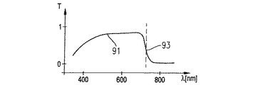
ビーム29は、カメラ55が物体の赤外線像を検出し得るように、カメラアダプタ光学系53を介してカメラ55の感光要素に与えられる。フィルタ57がビーム29に配置されている。フィルタ57の透過特性は、図2aにライン58として模式的に示されている。図2aの垂直線59はさらに、780nmでの蛍光物質、インドシアニングリーン(ICG)の最大励起スペクトルをあらわす。図2aの垂直線60は、835nmでのICGの対応する最大蛍光発光スペクトルをあらわす。フィルタ57の透過特性58は、約810nmで閾値61を示している。フィルタ57は、閾値より低い波長で実質的に非透過性であり、フィルタ57は、閾値より高い波長で実質的に透過性を有する。このように、物質の蛍光が、さらに以下に示すように顕微鏡システム1の照射システム63で励起する限り、カメラ55は、物体9内の蛍光物質の分散を表す物体9の像を検出する。
カメラ55で検出した像は、データ線65を介してコントローラ35に伝達される。コントローラ35は、カメラ55で検出した像を像データとしてデータ線67を介してLCDディスプレイ69に伝達する。LCDディスプレイ69は、コリメーター光学系70および部分透過ミラー68によって部分ビーム15と重なる像として像データを表す。ディスプレイ69の像は、物体9の直接光学像と重なって、使用者の眼19によって知覚され得る。LCDディスプレイ69は、緑色などの可視の色でカメラ55によって検出される赤外光強度分布を表す。物体9を形成するヒトの組織が含む緑色は、通常比較的少量であるので、赤外線像を表すために緑色を用いるとよいかもしれない。
The image detected by the
コントローラは、ディスプレイ51が、カメラ55によって検出された赤外光像をカメラ32によって検出された可視光像と重ねて表示するように頭部装着ディスプレイ49のディスプレイ51に伝達される像データのデータ処理を行う。このように、ディスプレイ49を頭に装着している使用者はまた、物体の可視光像および赤外光像の重なった表示を右眼で知覚する。
The controller controls the data of the image data transmitted to the display 51 of the head-mounted display 49 so that the display 51 displays the infrared light image detected by the
参照を簡素に分かりやすくするために、図1に図示はしていないが、さらなるビームが、左眼18に与えられる部分ビーム14から分岐してもよい。このようなさらなるビームは、部分ビーム15、LCDディスプレイ69、コリメータ光学系70および部分透過ミラー68のための上で説明した可視光の部分ビーム14と重なる像を生成するためにさらなる赤外線カメラに与えてもよい。使用者は、このとき、物体9の立体的な赤外光像を知覚する。このような付加的なカメラによって生成された像データはまた、頭部装着ディスプレイ49もまた、物体9内の蛍光物質の分散の立体表示を提供するように頭部装着ディスプレイ49のディスプレイ52に与えてもよい。
Although not shown in FIG. 1 for simplicity of reference, additional beams may branch off from the
照明システム63は、光源としてのハロゲンランプ71、反射器72,1つまたは複数のレンズ75を通り光学ファイバー束77の入端部76へと向かう平行化された光ビーム74を生成するためのコリメータ73を含み、これにより、光源71から放出された光をファイバー束77へと結合する。光は、ファイバー束77によって対物レンズ5近傍の位置まで運ばれ、ファイバー束77の出射口端部78から発散する。物体9に向かう照射光ビーム81を形成するために、発散している光を整形するためのコリメータ光学系79が設けられている。本実施形態は、光源としてハロゲンランプを用いることに限定しない。キセノンランプのような他の光源を用いてもよい。
The
図1において、コリメータ光学系79は、対物レンズ5の比較的近傍に位置している。しかし、照射光ビーム81は、対物レンズ5の光軸7に対して比較的高い角度の方向に向いている。照射光ビーム81の方向と対物レンズの光軸7の方向と角度がこのように高いと、物体への照射が不十分となる虞がある。特に、動脈瘤の治療のための人間の脳にあるような体内に備わった深い空孔で外科的な方法が行われるような状況においては、互いに重なった可視光像と蛍光像の両方を知覚することができない虞がある。このような、そして他の応用において、照射光ビームが光学軸7への角度が低い方向に向いているような照射システムの構造を用いることが好ましい。これは、照射光ビームのビーム路に対物レンズを含めることによって、すなわち、照射光ビームが対物レンズを通過することによって、または、対物レンズが、照射光ビームによって貫通される開口を備えることによって、従来から達成されている場合がある。
In FIG. 1, the collimator
照射システム63は、互いに隣接して配置される2つのフィルタ84および85を有するフィルタ板83をさらに含んでいる。コントローラ35によって制御されるアクチュエータ87が、フィルタ84が板83の第1の位置でビーム74に配置され、フィルタ85が板83の第2の位置でビーム74に配置されるように、図1の双方向矢印88が示す方向にフィルタ板83を移動させるために設けられている。
フィルタ84の透過特性を線89として図2bに示し、以下の表1に表す。
The transmission characteristic of filter 84 is shown in FIG. 2b as

蛍光を観察することが必要でない応用において、コントローラ35は、アクチュエータ87を駆動して、フィルタ85がビーム74に配置されるようにフィルタ板83を移動させる。フィルタ85の透過特性を線91として図2cに模式的に示し、表2に表す。
In applications where it is not necessary to observe the fluorescence, the
コントローラは、一連の像またはカメラ55で検出されたこのような像を表す像データを保存するための像メモリ95をさらに含む。コントローラ35は、さらに、メモリ95で保存された像メータをディスプレイ69に順次与え、ディスプレイ69は、時系列の像としてカメラ55によって先に検出された像を表示するように構成されている。一連の像はまた、頭部装着ディスプレイ49に与えられてもよい。
The controller further includes an
時系列の像のディスプレイは、赤外光像のフィルム表示として理解することもできる。このような表示は、蛍光物質が管システムに入るというプロセスにより管システムの構造または機能の評価および確認が可能になるような状況において好適に用いられる。蛍光物質が管に入った後のある時点に、検出された像は、経時的に実質的に不動であり、赤外光像のさらなる観察から得られる付加情報は実質的にない。このような管システムへの浸入プロセスは、1秒から5秒ほどの比較的短期間であるので、外科医は、非常に高い集中力でプロセスを監視し、問題の各管のためのプロセスの時間依存を記憶しなければならない。プロセス中にカメラ55によって検出された像を保存でき、かつ保存された像をフィルムとして繰り返し表示できることは、外科医が、観察されたプロセスの完全な印象を得ることに役立つ。
A display of a time-series image can also be understood as a film display of an infrared light image. Such an indication is preferably used in situations where the process by which the fluorescent material enters the tube system allows for the evaluation and confirmation of the structure or function of the tube system. At some point after the fluorescent material enters the tube, the detected image is substantially immobile over time, and there is substantially no additional information obtained from further viewing of the infrared light image. Since the intrusion process into such a tubing system is relatively short, on the order of 1 to 5 seconds, the surgeon monitors the process with very high concentration and the time of the process for each tube in question. Dependencies must be remembered. The ability to store the images detected by the
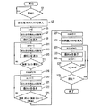
顕微鏡システム1を作動させる方法の一実施形態を図3のフローチャートを参照して以下に説明する。結像手順の初めに、熱保護フィルタ85を照射システム63のビーム路に配置し、コントローラは、ステップS1において、スイッチ97の開始ボタンまたは他の入力手段が外科医またはその助手によって作動されるのを待つ。蛍光物質が患者に注入直前または直後に開始ボタン97を作動させるのが好ましい。ステップS3において、アクチュエータが、熱保護フィルタ85をビーム路から取り除き、ビーム路に蛍光結像フィルタ84を挿入し、S5において、カウンタnをリセットする。その後、カメラ55によって検出された像B(0)をメモリ95に像データとして保存する。この像はまた、コントローラ35によってディスプレイ69に転送される。ディスプレイ69は、この像を外科医が接眼レンズ(S9)を覗き込むと物体9の可視光像と重ねてこの像を知覚するように表示する。その後,カウンタnをインクリメントさせ(S11)、次の像B(n)をカメラ55から受け取り、メモリ95に保存し(S13)、ステップS15において、この像B(n)をディスプレイ69または51に可視化する。
One embodiment of a method of operating the
観察中の管システムは、手順開始において蛍光物質を含んでいないので、最初に検出された像B(n)は、赤外光の強度を実質的に全く示していない。蛍光物質は患者の体内を伝播し、最終的に顕微鏡対物レンズ3の物体フィールドの組織領域9に入ることによって、像B(n)は、順次増加する赤外線強度を示す。コントローラ35は、像B(n)の強度を分析し、ステップS17で、その強度と第1の所定の閾値を比較する。一番最後に検出した像B(n)の強度が第1の閾値未満である場合、ステップS11に戻る。像B(n)の強度が第1の閾値より高ければ、これは、使用者に後に繰り返し表示されることになる一連の検出像の開始として用いられる時点を示している。ステップS19において、カウンタnの現在の値を変数nstartに割り当てる。
Since the tube system under observation does not contain any fluorescent material at the start of the procedure, the first detected image B (n) shows substantially no infrared light intensity. As the fluorescent material propagates through the body of the patient and finally enters the
その後、カウンタはインクリメントされ(S20)、次の像B(n)を得、保存し(S21)、表示する(S23)。ステップS25において、コントローラ35は、一番最後に検出した像B(n)の強度と最後から二番目の像B(n−1)の強度とを比較し、この2つの強度の差が、所定の第2の閾値より大きい場合、ステップS20に戻る。物質の管システムへの浸入開始直後は強度は増加し続けるので、その時点では、ステップS25の条件が満たされないように第2の閾値を選択する。ある時間が経過後、蛍光物質の濃度は飽和に近づき、次の像B(n)とB(n−1)の強度との差が第2の閾値より小さくなる。これは、一連の検出された像の終了すべき時点を示している。ステップS27において、カウンタnの現在値を変数nendeに割り当て、S29において、蛍光結像フィルタ84をビーム74から取り除き、熱保護フィルタ85をビーム74に挿入する。
Thereafter, the counter is incremented (S20), and the next image B (n) is obtained, stored (S21), and displayed (S23). In step S25, the
その後、ディスプレイ69または51に検出された像を繰り返し表示する手順が続く。このために、カウンタnを一連の像の開始に相当する値nstartに設定し(S31)、そこでB(n)を表示し(S33)、カウンタnをインクリメントする(S35)。ステップS37において、カウンタnの現在値が一連の像の終了時でのカウンタ値nendより低くなった場合、ステップ33に戻る。そうでなければ、ステップS39において、手順の終了を示すために再びボタン97を作動させるかどうかを判断する(S39)。手順終了が示されなければ、ステップS31に戻り、再び一連の像を表示する。 Thereafter, the procedure of repeatedly displaying the detected image on the display 69 or 51 continues. For this purpose, the counter n is set to a value nstart corresponding to the start of a series of images (S31), where B (n) is displayed (S33), and the counter n is incremented (S35). If the current value of the counter n is lower than the counter value nend at the end of a series of images in step S37, the process returns to step 33. Otherwise, in step S39, it is determined whether or not the button 97 is operated again to indicate the end of the procedure (S39). If the end of the procedure is not indicated, the process returns to step S31, and a series of images is displayed again.
上記の実施形態は、可視光で物体を照射する光ビームの生成および蛍光の励起のために1つの光源を用いるが、さらなる実施形態では、可視光および励起光の生成のために、それぞれの異なる光源を用いてもよい。このとき励起光を生成する光源は、応用によって電源をオンオフすることができる。 While the above embodiments use one light source for the generation of a light beam illuminating the object with visible light and the excitation of the fluorescence, in a further embodiment, a different light source is used for the generation of the visible light and the excitation light. A light source may be used. At this time, the power of the light source that generates the excitation light can be turned on and off depending on the application.
さらなる実施形態は、1つの光源によって生成される2つまたは複数の光ビーム、あるいは各ビームが可視光および励起光を含む別個の光源を含んでもよい。 Further embodiments may include two or more light beams generated by one light source, or separate light sources where each beam includes visible light and excitation light.
図1から図3を参照して上で説明したの実施形態において、顕微鏡システム1は、透過フィルタであるフィルタ84および85を用いている。別の実施形態では、光源の反射器72を適切にコーティングすることによって提供され得たり、分離した反射器がコントローラ35の制御によるアクチュエータを用いてビーム路に挿入されるというような所望のフィルタ特性を有する別個の反射器によって提供され得る、相当する反射フィルタを用いてもよい。
In the embodiment described above with reference to FIGS. 1 to 3, the
図1から図3を参照して上で説明した実施形態において、フィルター57、84および85ならびにそれぞれ図2a、2b、2cに示されたフィルタ特性を有する顕微鏡システム1は、インドシアニングリーンの蛍光を観察するために最適化されている。別の実施形態では、上記の原則は、特性89および58の端部90および61を別の蛍光物質の対応する励起波長および蛍光波長に当てはめることによって別の蛍光物質の観察に応用することができる。
In the embodiment described above with reference to FIGS. 1 to 3, the
図4は、顕微鏡システム1のさらなる実施形態のビーム路を模式的に示している。顕微鏡システムは、複数のレンズ5および6を有する対物レンズ3を含む。レンズ5および6はレンズ表面での可視光の反射を減らすように反射防止膜で覆われている。反射防止膜は、レンズ表面での赤外光および近赤外光の反射もまた減らすように設計されてもよい。
FIG. 4 schematically shows the beam path of a further embodiment of the
対物レンズ3は、対物レンズ3の物体平面11から発散している拡散ビーム9を受け入れる。拡散ビーム9は、対物レンズの下流で実質的に平行なビームを提供するために対物レンズによって変形される。対物レンズ3の下流であって、図4では対物レンズの上方に、図4に模式的に示される2つのズームシステム13および14が備えられている。各ズームシステム13、14は、それぞれ、部分ビーム15、16を用い、これをそれぞれ、顕微鏡システムの接眼レンズ17、18に与える。使用者は、それぞれ、右眼および左眼で接眼レンズ17および18を覗き込むことにより物体平面11の拡大された鮮明な像を知覚することができる。可視光は、物体平面11のこれらの像を生成するために用いられる。このために、物体平面11は、キセノンランプ23ならびにビーム整形レンズ24および26を含む照射システム21によって与えられる可視光で照射される。
The
顕微鏡システム1は、可視光での物体平面の実質的に鮮明な像を検出するカメラ33をさらに有している。カメラ33は、像平面37に位置する感光基板を有するCCDカメラチップ35を含む。ビームスプリッタ29が部分ビーム16に設けられており、そこからビーム31が分岐し、ビーム31はカメラアダプタ光学系39に与えられ、次いで、ビーム31はカメラに与えられ、物体平面11の実質的に鮮明な像が像平面37に生成される。カメラ33で検出された像は、資料用に用いることもできるし、接眼レンズ17および18を直接用いない使用者のために物体平面11の像を表示するための表示装置によって表示されることもできる。カメラ33の像は、特に、使用者の頭部装着ディスプレイに与えられてもよい。
The
顕微鏡システム1は、赤外線で物体平面の像を検出するためのカメラ41を含む。カメラ41は、像平面45に位置する感光基板を有するCCDカメラチップ43を含む。ビームスプリッタ49によって部分ビーム15から分岐されたビーム51をCCDカメラチップ43に与えるためにカメラアダプタ光学系47が設けられている。カメラアダプタ光学系47は、物体平面11の実質的に鮮明な像が赤外光で像平面45に生成されるように構成されている。このように、カメラ33および41は、カメラ33は、物体平面11の実質的に鮮明な像を可視光で生成し、カメラ41は、物体平面の実質的に鮮明な像を赤外光で生成するという点で互いに異なっている。従来からの定義によると、赤外光は、820nmから870nmの範囲の波長を含む。
The
フィルタ53が、ビーム51中であってカメラ41の正面に配置されている。フィルタ53は、応用に用いられる蛍光物質に適合している。本実施例では、フィルタ53は、インドシアニングリーンに適合しており、実質的に820nmと870nmとの間の波長範囲の光のみを透過する。インドシアニングリーンの蛍光波長はこの波長範囲内である。 A filter 53 is located in the beam 51 and in front of the camera 41. Filter 53 is compatible with the fluorescent material used in the application. In this embodiment, the filter 53 is compatible with indocyanine green and transmits substantially only light in the wavelength range between 820 nm and 870 nm. The fluorescence wavelength of indocyanine green is within this wavelength range.
別の実施形態によると、ビームスプリッタ49は、ビームスプリッタ49が赤外光のみを偏向させるように適切な被膜で覆われている。 According to another embodiment, the beam splitter 49 is covered with a suitable coating such that the beam splitter 49 deflects only infrared light.
カメラ41によって検出された像は、コントローラまたはコンピュータ55に与えられる。
The image detected by the camera 41 is provided to a controller or a
ある実施形態による応用では、人間の肝臓などの被検組織を物体平面11に置く。接眼レンズ17および18によって与えられる可視光像だけで組織を観察する場合、組織を貫通して延びる血管は、実質的に不可視である。血管と周囲の肝臓組織とをこのような像から区別するのは容易ではない。ICGの静脈注射の後、蛍光物質は、周囲の組織によりも血管に高い濃度で蓄積する。820nmから870nmの波長範囲の光を用いた組織の像は、周囲の組織に比較して蛍光した管に対応する部分において高い強度を示す。
In an application according to an embodiment, a test tissue, such as a human liver, is placed on the
カメラ41によって検出され、コントローラ55に与えられた像の例を図5aに模式的に示す。結像フィールド58の大部分57の強度は大変低い。部分59は、わずかに高い強度を示し、2つの部分61、62は、さらに高い強度を示している。より高い強度の赤外線を示している部分63が部分61内に存在する。部分62および63は、血管に相当し、部分57は周囲の組織に相当すると考えられる。さらに、部分59は蛍光物質が低い濃度で蓄積している周囲の組織に相当すると考えられる。
An example of an image detected by the camera 41 and provided to the
顕微鏡システム1は、平面67に位置するLCDチップ69を含む表示システム65をさらに含む。LCDチップ69で表示された像は、投影光学系71およびビームスプリッタ73によって部分ビーム15と重ねられる。使用者は、接眼レンズ17を覗き込むと、物体平面の可視光像とディスプレイ65によって生成された像表示との重なりを知覚することができる。コントローラ55は、図5aに模式的に示すような、像をディスプレイ65に与えることができる。像が表示され、例えば青色の可視光で使用者に知覚される。このように、使用者は、可視光像と重なる赤外線像の可視的な表示が与えられる。このとき、使用者は、顕微鏡システム1の物体フィールド内に位置した血管を認識することができる。
The
しかし、可視光像と図5aによる像とを重ねるために、部分61および62は、その部分内が青色で示されているので、可視光像から得られ得る情報が減少する。この状況を改善するために、コントローラ55は、カメラ41から受け取られた像の分析を行う。コントローラは、これらの所定の閾値より大きな強度を示す像のコヒーレント部分を判断する。適切な所定の閾値を用いて、血管と周囲の組織との区別を行うことができる。図5aに示す例において、閾値は、部分59における強度が閾値より低く、部分62および63内の強度が閾値より高くなるように調整されている。
However, due to the superposition of the visible light image and the image according to FIG. 5a, the information that can be obtained from the visible light image is reduced since the
閾値を超えるコヒーレント部分を同定したあと、コントローラ55は、コヒーレント領域を囲む外周線を決定する。このような外周線は、像のコヒーレント部分と周囲部分との境界に相当する。コントローラ55は、外周線を表すデータをディスプレイ65に与える。ディスプレイは外周線の像を生成し、このような像を5bに模式的に図示するように可視光像と重ねる。この像において、部分61および62の外周線75のみが青色で示されている。このように、使用者は、外周線75の内側に位置する血管に関する情報を与えられ、使用者は、通常どおり血管の可視光像も依然として知覚することができ、これらの血管の可視光像を観察しながら、血管の外科治療を行うことができる。
After identifying the coherent portions that exceed the threshold, the
フィルタ77は、照射システム21のビーム路に配置されている。フィルタ77は、蛍光物質の蛍光発光の波長を実質的に透過しない。物質の蛍光が比較的高いコントラストおよび低いバックグラウンドでカメラ41によって検出された像において見えるように、蛍光の光で物体を照明しない。
The filter 77 is arranged in the beam path of the
さらに、照明システム21のビーム路にフィルタチョッパ79が配置されている。フィルタチョッパ79は、コントローラ55によって制御されているモータ89によって回転駆動されている。フィルタチョッパは、750nmと820nmとの間の範囲の波長で実質的に透過するセクタと透過しないセクタとの複数のセクタを含む。フィルタチョッパ79のすべてのセクタは、実質的に可視光を透過する。蛍光物質の励起はフィルタチョッパ79を回転させることによって変調される。したがって、カメラ41によって検出された蛍光像の強度も経時的に変調され、コントローラ55は、蛍光像におけるノイズおよびバックグラウンドをさらに減らすためのロックイン方法などの方法によって蛍光像の時間依存を分析してもよい。
Furthermore, a
上記の照射システムの別の実施形態は、図4の鎖線に示されている。別の照射システム90は、光源23と分離した光源91を含む。光源91は、可視光で物体を照射するために設けられており、光源23は、蛍光物質の励起光を生成するためだけに設けられている。このように、可視光での照射は励起光での照射とは独立し、チョッパホイール79の回転が、可変を変調すると、使用者が物体の可視光像を観察できない場合があることから、可視光での照射を変調しないようにしてもよい。さらなる実施形態によると、光源23は、励起光を変調するためのコントローラ55によって素早く電源のオンオフが行われるレーザ光源である。このような実施形態では、光変調チョッパを省いてもよい。
Another embodiment of the above illumination system is shown in dashed lines in FIG. Another
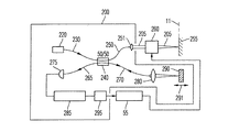
顕微鏡システムは、分析光ビーム205を発光し、分析光ビーム205をビームスキャナ260に向ける光干渉断層撮影(OCT)装置200をさらに含む。ビームスキャナー260は、分析光ビームを物体平面11に向け、分析光ビーム205を物体平面に集束するためのミラーを含む。ビームスキャナー260は、物体平面上の分析光ビーム205が向けられる位置を選択し、これらの位置を変更するようにコントローラ55によって制御される。OCT装置200は、選択された位置で物体の深さプロファイルデータを検出し、コントローラ55に深さプロファイルデータを送る。OCT装置は当該技術分野から周知である。例えば、米国特許5、493、109号および5、795、295号があり、これらの全開示を参照により本明細書に援用する。
The microscope system further includes an optical coherence tomography (OCT)
図6を参照して、OCT装置200の機能を以下に簡単に説明する。装置200は、光ファイバー230に結合された放射線を発する白色光源220を含む。ビームカップラー240が、その放射線を2つの光ファイバ250および270に結合するために設けられている。ファイバ270の1つの部分ビームが、レンズ280を介して基準ミラー290に向かう。ファイバ250の部分ビームは、分析光ビーム205としてレンズ251を介して平行化され、ビームスキャナ260に向かう。ビームスキャナ260は、分析光ビーム205を被検物体255に向ける。物体から戻ってきた分析光ビーム205の放射線は、ビームスキャナ260によって逆方向にOCT装置200へと送られ、ファイバ250に結合される。ミラー290から反射し戻ってきた放射線もまた、ファイバ270に結合される。ビームカップラ240は、ファイバ250を介して物体から受け取った放射線と、ファイバ270を介してミラー290で反射し戻ってきた放射線とを重ね、重ねられた放射線をファイバ265に結合する。ファイバ265は、重ねられた放射線を光検知器275に送る。光検知器の出力は、復調器285によって復調され、アナログ・デジタル変換器295によってコンピュータ読み取り可能データに変換され、コントローラ55に送られる。
With reference to FIG. 6, the function of the
物体255およびミラー290からの放射線を受け入れる検出器275は、ビームスプリッタ240とビームスプリッタ240での重ね合わせとで2つの部分ビームの光学波長が光源の可干渉長さ内で等しい場合、干渉によって増加する信号を検出する。このように等しい光学ビーム路を達成するために、基準ミラー290は、図6における矢印291で示される方向に移動可能である。ミラー290を移動させ、検出器275によって検出された対応する強度を記録することによって、物体255の分析光ビーム205が向かう位置での物体255の深さプロファイルを検出することが可能である。ミラー290が機械的に移動しなければならないので、このような深さプロファイルを得るには時間がかかる。
コントローラ55は、物体の深さプロファイルを記録すべき位置に分析光ビーム205を向けるようにビームスキャナ260を制御する。コントローラ55は、図5bにおいて参照番号62および63で示される蛍光像からコントローラ55によって先に決定された部分または分析領域に関してのみ、深さプロファイルの記録を行う。
The
コントローラ55は、深さプロファイルが部分62、63内の直線213に位置する複数の部分で記録されるようにビームスキャナ260を制御する。ここで、直線213は、可視フィールド58に垂直に配置され、互いに所定の距離をもって配置されている。線211に沿って記録された深さプロファイルは、顕微鏡システム1のディスプレイ207に表示される。キーボード209またはマウスなどの他の入力手段を、可視フィールド58内の直線213の構成、例えば、その向きおよび互いの距離などを選択するために用いることができる。さらに、部分62、63のうちの1つを選択して、選択された部分の深さプロファイルをディスプレイ207に示さないようにすることもできる。
The
結像システム65によって深さプロファイルのうちいくつかの選択されたものを表示し、使用者が接眼レンズを通して物体の像を観察しながら深さプロファイルを分析できるように、このような表示と接眼レンズを通して知覚された可視光像とを重ねることも可能である。 Such displays and eyepieces are displayed by the imaging system 65 so that some selected ones of the depth profiles can be displayed and analyzed by the user while observing the image of the object through the eyepiece. It is also possible to overlap with the visible light image perceived through.
上記の実施形態では、インドシアニングリーンが蛍光物質として用いられている。しかし、他の蛍光物質を用いてもよい。特に、人体の物質の自発蛍光を観察することもできる。蛍光像の強度の分析の代わりに、またはそれに加えて、物体フィールド内の蛍光領域を互いに区別するために蛍光半減期を分析することもできる。 In the above embodiment, indocyanine green is used as the fluorescent substance. However, other fluorescent substances may be used. In particular, the spontaneous fluorescence of a substance in the human body can be observed. Instead of or in addition to analyzing the intensity of the fluorescence image, the fluorescence half-life can also be analyzed in order to distinguish the fluorescent areas in the object field from one another.
さらなる実施形態によると、表示装置65によって生成された像を部分ビーム15ではなく部分ビーム16に結合する。あるいは、対応の表示を両方の部分ビームに結合してもよい。
According to a further embodiment, the image generated by the display 65 is combined into a
上記の実施形態において、外周線75は実線で表されている。さらなる実施形態によると、外周線は破線、点線、一点鎖線または他のタイプの線で表されてもよく、コヒーレント部分内を像の影領域または斜線領域として表してもよい。
In the above embodiment, the outer
したがって、本発明は、本明細書において最も実用的で好適な実施形態であると考えられたもので示され、記載されているが、本発明の範囲内でこれらから離れることができることが理解され、したがって、本明細書中に開示された詳細に限定されるのではなく、請求項の全範囲は、いずれのおよびすべての均等な方法および装置を含む。 Thus, while the invention has been illustrated and described herein as considered to be the most practical and preferred embodiments, it is understood that departures therefrom without departing from the scope of the invention. Accordingly, rather than being limited to the details disclosed herein, the full scope of the claims includes any and all equivalent methods and devices.
Claims (38)
以下のものを含む顕微鏡光学系と、
すなわち、物体領域を、前記物体領域の像を表している第1の像データを生成するための第1のカメラの光検出構成要素上に、インドシアニングリーンの蛍光発光波長を含む第1の波長範囲の波長を含む光で光学的に結像するための第1のビーム路と、
前記物体領域の拡大された第1の表示を提供するための第2のビーム路であって、前記第1の表示が、前記物体領域の像を、少なくとも可視光を含む第2の波長範囲の波長を含む光で表す第2のビーム路とを含む顕微鏡光学系と、
使用者による観察のために、前記第1の像データを基準として生成された第2の表示を前記第1の表示と重ねて表示するための表示システムと、
前記物体領域上に向かう少なくとも1つの照射光ビームを提供するための照射システムであって、前記少なくとも1つの照射光ビームは、前記第2の波長範囲の波長およびインドシアニングリーンの励起波長の光を含む照射システムとを含むことを特徴とする顕微鏡システム。 A microscope system for visualizing indocyanine green fluorescence in a test object,
Microscope optics, including:
That is, a first wavelength including a fluorescence emission wavelength of indocyanine green on a light detection component of a first camera for generating first image data representing an image of the object region. A first beam path for optically imaging with light comprising a range of wavelengths;
A second beam path for providing an enlarged first representation of the object area, wherein the first representation provides an image of the object area in a second wavelength range that includes at least visible light. A microscope optical system including a second beam path represented by light including a wavelength;
A display system for displaying a second display generated on the basis of the first image data so as to overlap the first display for observation by a user;
An illumination system for providing at least one illumination light beam directed onto said object region, wherein said at least one illumination light beam emits light at a wavelength in said second wavelength range and an excitation wavelength of indocyanine green. And an irradiation system.
以下のものを含む顕微鏡光学系と、
すなわち、物体領域を、前記物体領域の像を表している第1の像データを生成するための第1のカメラの光検出構成要素上に、蛍光物質の蛍光発光波長を含む第1の波長範囲の波長を含む光で光学的に結像するための第1のビーム路と、
前記物体領域の拡大された第1の表示を提供するための第2のビーム路であって、前記第1の表示が、前記物体領域の像を、少なくとも可視光を含む第2の波長範囲の波長を含む光で表す第2のビーム路とを含む顕微鏡光学系と、
少なくとも一定期間、前記第1のカメラによって検出された1組の第1の像データを保存するための像メモリと、
前記1組の第1の像データの少なくとも1つのサブセットから生成された第2の表示のシーケンスを表示するための表示システムであって、使用者による観察のために、前記第2の表示のシーケンスが、前記第1の表示と重ねて表示される表示システムとを含むことを特徴とする顕微鏡システム。 A microscope system for visualizing fluorescence of a fluorescent substance in a test object,
Microscope optics, including:
That is, a first wavelength range including a fluorescence emission wavelength of a fluorescent substance is provided on a light detection component of a first camera for generating first image data representing an image of the object area. A first beam path for optically imaging with light having a wavelength of
A second beam path for providing an enlarged first representation of the object area, wherein the first representation provides an image of the object area in a second wavelength range that includes at least visible light. A microscope optical system including a second beam path represented by light including a wavelength;
An image memory for storing a set of first image data detected by the first camera for at least a certain period of time;
A display system for displaying a second sequence of displays generated from at least a subset of the set of first image data, wherein the second sequence of displays is for viewing by a user. Includes a display system that is displayed in an overlapping manner with the first display.
以下のものを含む顕微鏡光学系と、
すなわち、物体領域を、前記物体領域の像を表している第1の像データを生成するための第1のカメラの光検出構成要素上に、蛍光物質の蛍光発光波長を含む第1の波長範囲の波長を含む光で光学的に結像するための第1のビーム路と、
前記物体領域の拡大された第1の表示を提供するための第2のビーム路であって、前記第1の表示が、前記物体領域の像を、少なくとも可視光を含む第2の波長範囲の波長を含む光で表す第2のビーム路とを含む顕微鏡光学系と、
前記物体領域上に向かう少なくとも1つの照射光ビームを提供するための照射システムであって、前記少なくとも1つの照射光ビームは、前記蛍光物質の励起波長の光を含み、前記照射システムが、前記蛍光物質の励起波長の光の強度を変調するための光変調器を含む照射システムと、
使用者による観察のために、前記第1の像データを基準として生成された第2の表示を前記第1の表示と重ねて表示するための表示システムとを含むことを特徴とする顕微鏡システム。 A microscope system for visualizing fluorescence of a fluorescent substance in a test object,
Microscope optics, including:
That is, a first wavelength range including a fluorescence emission wavelength of a fluorescent substance is provided on a light detection component of a first camera for generating first image data representing an image of the object area. A first beam path for optically imaging with light having a wavelength of
A second beam path for providing an enlarged first representation of the object area, wherein the first representation provides an image of the object area in a second wavelength range that includes at least visible light. A microscope optical system including a second beam path represented by light including a wavelength;
An illumination system for providing at least one illumination light beam onto said object area, said at least one illumination light beam comprising light at an excitation wavelength of said fluorescent material, said illumination system comprising: An illumination system including an optical modulator for modulating the intensity of light at the excitation wavelength of the substance;
A display system for displaying a second display generated based on the first image data on top of the first display for observation by a user.
物体領域を、前記物体領域の像を表している第1の像データを生成するための第1のカメラの光検出構成要素上に光学的に結像するための第1のビーム路を有する顕微鏡光学系と、
前記物体領域に向かう少なくとも1つの照射光ビームを提供する照射システムであって、前記照射システムは、第1の位置に位置付け可能な第1のフィルタを含み、その位置において前記第1のフィルタは、照射システムのビーム路内に配置されており、前記第1のフィルタは、所定の波長より高い波長の光を前記照射光ビームから排除し、前記照射システムが、前記第1のフィルタがビーム路内に位置していない第2の位置から前記第1の位置へ前記第1のフィルタを移動させるためのアクチュエータを含む照射システムと、
前記第1のフィルタをその第2の位置からその第1の位置まで、前記第1の像データによって表された像の強度の分析に基づいて移動させるための前記アクチュエータを制御するように構成されたコントローラとを含むことを特徴とする顕微鏡システム。 A microscope system for inspecting an object,
A microscope having a first beam path for optically imaging an object area on a light detection component of a first camera for generating first image data representing an image of the object area. Optics,
An illumination system for providing at least one illumination light beam directed to said object region, said illumination system including a first filter positionable at a first location, wherein said first filter comprises: Being located in a beam path of an illumination system, the first filter rejects light of a wavelength higher than a predetermined wavelength from the illumination light beam, wherein the illumination system includes: An illumination system including an actuator for moving the first filter from a second position not located at the first position to the first position;
And configured to control the actuator for moving the first filter from the second position to the first position based on an analysis of an intensity of an image represented by the first image data. A microscope system comprising: a controller;
以下のものを含む顕微鏡光学系と、
すなわち、物体領域を、前記物体領域の像を表している第1の像データを生成するための第1のカメラの光検出構成要素上に、蛍光物質の蛍光発光波長を含む第1の波長範囲の波長を含む光で光学的に結像するための第1のビーム路と、
前記物体領域の拡大された第1の表示を提供するための第2のビーム路であって、前記第1の表示が、前記物体領域の像を、少なくとも可視光の波長を含む第1の波長範囲の光で表す第2のビーム路とを含む顕微鏡光学系と、
前記物体領域の像のコヒーレント部分の少なくとも外周線を表している第2の像データを生成するように構成されたコントローラであって、前記コヒーレント部分内の像の光強度が閾値を超えるようなコントローラと、
使用者による観察のために、前記第2の像データを基準として生成された第2の表示を前記第1の表示と重ねて表示するための表示システムとを含むことを特徴とする顕微鏡システム。 A microscope system for visualizing fluorescence of a fluorescent substance in a test object,
Microscope optics, including:
That is, a first wavelength range including a fluorescence emission wavelength of a fluorescent substance is provided on a light detection component of a first camera for generating first image data representing an image of the object area. A first beam path for optically imaging with light having a wavelength of
A second beam path for providing an enlarged first representation of the object area, wherein the first representation converts an image of the object area to a first wavelength including at least a wavelength of visible light. A microscope optics including a second beam path represented by a range of light;
A controller configured to generate second image data representing at least an outer perimeter of a coherent portion of the image of the object region, wherein the light intensity of the image in the coherent portion exceeds a threshold. When,
A display system for displaying a second display generated based on the second image data as a reference on the first display for observation by a user.
前記第1の像データによって表された前記物体領域の像の少なくとも1つのコヒーレント部分を表している位置データを生成するように構成されたコントローラであって、前記少なくとも1つのコヒーレント部分内の像の光強度が閾値を超えるコントローラと、
前記生成された位置データに基づいて分析ビームで前記物体領域を走査するためのビームスキャナと前記物体から戻ってきた分析ビームの放射線の強度を表す深さプロファイルデータを得るための放射線検出器とを有する干渉計装置とを含むことを特徴とする顕微鏡システム。 The object region includes a first wavelength range including a fluorescence emission wavelength of a fluorescent material on a light detection component of a first camera for generating first image data representing an image of the object region. A microscope optical system having a first beam path for optically imaging with light;
A controller configured to generate position data representing at least one coherent portion of an image of the object region represented by the first image data, wherein the controller generates position data representing an image in the at least one coherent portion. A controller whose light intensity exceeds a threshold,
A beam scanner for scanning the object area with the analysis beam based on the generated position data, and a radiation detector for obtaining depth profile data representing the intensity of the radiation of the analysis beam returned from the object. A microscope system comprising: an interferometer device having the same.
使用者による観察のために第1の可視光像の表示を行うステップと、
インドシアニングリーンの蛍光発光波長を含む光で前記物体の第2の像を記録するステップと、
使用者による観察のために前記第2の像を前記第1の像と重ねて表示するステップと、
前記可視光およびインドシアニングリーンの励起波長の光を含む少なくとも1つの照射光ビームで前記物体を照射するステップとを含む顕微鏡検査方法。 A microscopy method for visualizing indocyanine green fluorescence in a test object,
Displaying a first visible light image for observation by a user;
Recording a second image of the object with light comprising a fluorescence emission wavelength of indocyanine green;
Displaying the second image superimposed on the first image for observation by a user;
Irradiating said object with at least one irradiating light beam comprising said visible light and light of an indocyanine green excitation wavelength.
使用者による観察のために前記物体の拡大された第1の表示を行うステップであって、前記物体の蛍光が、前記第1の表示に実質的に可視でないステップと、
一定期間、前記物体の一連の蛍光像を記録するステップと、
前記期間が経過後、前記一連の蛍光像が使用者に可視であるように、かつ前記物体の拡大された第1の表示と重ねて、前記物体の記録された一連の蛍光像を表示するステップとを含む顕微鏡検査方法。 A microscopy method for visualizing fluorescence of a test object,
Providing a magnified first display of the object for observation by a user, wherein the fluorescence of the object is not substantially visible in the first display;
Recording a series of fluorescent images of the object for a period of time;
Displaying, after the time period, a series of recorded fluorescent images of the object such that the series of fluorescent images is visible to a user and superimposed on an enlarged first display of the object. And a microscopy method comprising:
所定の波長より高い波長を含む光で前記物体を照射し、前記所定の波長より高い波長の光で物体を照射している間、前記物体の一連の像を記録するステップと、
前記所定の波長より高い波長の光での物体の照射を、前記記録された像の分析に基づいて終了し、前記所定の波長より小さな波長のみを含む光で前記物体を照射するステップと、
使用者による観察のために、限定の波長より小さな波長のみを含む光で照射された物体の表示を行い、使用者による観察のために、前記記録された一連の像の分析に応じて生成された表示を行うステップとを含む顕微鏡検査方法。 A microscopy method for visualizing a test object,
Irradiating the object with light including a wavelength higher than a predetermined wavelength, and while irradiating the object with light having a wavelength higher than the predetermined wavelength, recording a series of images of the object,
Irradiating the object with light having a wavelength higher than the predetermined wavelength based on the analysis of the recorded image, and irradiating the object with light including only a wavelength smaller than the predetermined wavelength;
Displaying an object illuminated with light containing only wavelengths less than the limited wavelength for viewing by a user, and generating, in response to analysis by the recorded series of images, for viewing by a user. Performing a displayed image.
被検物体を可視光を含む第1の波長範囲の光で照射するステップと、
前記第1の波長範囲の光で前記物体の像を生成するステップと、
前記第1の波長範囲と部分的にしか重ならないか、または前記第1の波長範囲と全く重ならない第2の波長範囲の光で前記物体の像を記録するステップと、
前記記録された像を分析し、前記記録された像の少なくとも1つのコヒーレント部分を同定するステップであって、前記少なくとも1つのコヒーレント部分内の前記像の強度の値が閾値を超えるステップと、
前記少なくとも1つのコヒーレント部分の外周の表示を生成し、この表示を前記第1の波長範囲の前記物体の像と重ねて表示するステップとを含む顕微鏡検査方法。 A microscopy method for visualizing a test object,
Irradiating the test object with light in a first wavelength range including visible light;
Generating an image of the object with light in the first wavelength range;
Recording an image of the object with light in a second wavelength range that only partially overlaps the first wavelength range or does not completely overlap the first wavelength range;
Analyzing the recorded image to identify at least one coherent portion of the recorded image, wherein a value of the intensity of the image within the at least one coherent portion exceeds a threshold;
Generating an indication of the periphery of said at least one coherent portion and displaying the indication superimposed on an image of the object in the first wavelength range.
前記記録された像を分析し、前記記録された像の少なくとも1つのコヒーレント部分を同定するステップであって、前記少なくとも1つのコヒーレント部分内の前記記録された像の強度の値が閾値を超えるステップと、
前記少なくとも1つの同定されたコヒーレント部分に応じて決定された分析領域のみの深さプロファイルデータを得るステップであって、前記分析領域が、物体フィールドより小さいステップとを含む顕微鏡検査方法。 Recording an image of the object field with light including the excitation wavelength of the fluorescent material;
Analyzing the recorded image to identify at least one coherent portion of the recorded image, wherein a value of the intensity of the recorded image within the at least one coherent portion exceeds a threshold value When,
Obtaining depth profile data only for an analysis region determined according to said at least one identified coherent portion, said analysis region being smaller than an object field.
Applications Claiming Priority (2)
| Application Number | Priority Date | Filing Date | Title |
|---|---|---|---|
| DE10239514 | 2002-08-28 | ||
| DE10304268 | 2003-02-03 |
Related Child Applications (1)
| Application Number | Title | Priority Date | Filing Date |
|---|---|---|---|
| JP2010006800A Division JP5489336B2 (en) | 2002-08-28 | 2010-01-15 | Microscope system, operation method of microscope system, surgical microscope, and operation method of surgical microscope |
Publications (1)
| Publication Number | Publication Date |
|---|---|
| JP2004163413A true JP2004163413A (en) | 2004-06-10 |
Family
ID=32471476
Family Applications (2)
| Application Number | Title | Priority Date | Filing Date |
|---|---|---|---|
| JP2003304783A Pending JP2004163413A (en) | 2002-08-28 | 2003-08-28 | Microscope system and microscope inspection method |
| JP2010006800A Expired - Lifetime JP5489336B2 (en) | 2002-08-28 | 2010-01-15 | Microscope system, operation method of microscope system, surgical microscope, and operation method of surgical microscope |
Family Applications After (1)
| Application Number | Title | Priority Date | Filing Date |
|---|---|---|---|
| JP2010006800A Expired - Lifetime JP5489336B2 (en) | 2002-08-28 | 2010-01-15 | Microscope system, operation method of microscope system, surgical microscope, and operation method of surgical microscope |
Country Status (3)
| Country | Link |
|---|---|
| US (6) | US7580185B2 (en) |
| JP (2) | JP2004163413A (en) |
| DE (4) | DE10339784B4 (en) |
Cited By (31)
| Publication number | Priority date | Publication date | Assignee | Title |
|---|---|---|---|---|
| JP2006296516A (en) * | 2005-04-15 | 2006-11-02 | Mitaka Koki Co Ltd | Bright-field light source for fluorescence observation and surgical microscope loaded with the same |
| JP2007122048A (en) * | 2005-10-06 | 2007-05-17 | Carl Zeiss Surgical Gmbh | Microscopic inspection system and recording method for visualizing fluorescence |
| JP2008049168A (en) * | 2006-08-25 | 2008-03-06 | Carl Zeiss Surgical Gmbh | Surgical microscope having lighting system |
| JP2008161721A (en) * | 2008-03-26 | 2008-07-17 | Mitaka Koki Co Ltd | Surgical microscope attachment |
| JP2008249669A (en) * | 2007-03-30 | 2008-10-16 | Osaka Prefecture Univ | Method and device for recognizing and identifying substance and object, fluorescence microscope, headup display unit |
| JP2008264489A (en) * | 2007-04-24 | 2008-11-06 | Carl Zeiss Surgical Gmbh | Operation microscope equipped with oct system and illumination module for operation microscope equipped with oct system |
| WO2009072630A1 (en) * | 2007-12-07 | 2009-06-11 | Mitaka Kohki Co., Ltd. | Medical stand device, medical microscope, and external illuminating device |
| JP2009136581A (en) * | 2007-12-07 | 2009-06-25 | Mitaka Koki Co Ltd | Medical device |
| JP2009136577A (en) * | 2007-12-07 | 2009-06-25 | Mitaka Koki Co Ltd | Medical stand device |
| JP2009136578A (en) * | 2007-12-07 | 2009-06-25 | Mitaka Koki Co Ltd | Medical microscope |
| JP2009525495A (en) * | 2006-01-30 | 2009-07-09 | カール ツァイス サージカル ゲーエムベーハー | Microscope system |
| JP2010213995A (en) * | 2009-03-18 | 2010-09-30 | Olympus Medical Systems Corp | Surgical microscope |
| JP2011027895A (en) * | 2009-07-23 | 2011-02-10 | Mitaka Koki Co Ltd | Microscope system |
| JP2011523100A (en) * | 2008-06-13 | 2011-08-04 | カール ツァイス サージカル ゲーエムベーハー | Optical observation instrument with multi-channel data insertion |
| JP2012058732A (en) * | 2010-09-06 | 2012-03-22 | Leica Microsystems (Schweiz) Ag | Surgical fluorescence stereomicroscope |
| JP2012098271A (en) * | 2010-08-09 | 2012-05-24 | Carl Zeiss Meditec Ag | Filter pair, fluorescence observation system, and method of carrying out fluorescence observation |
| JP2013003495A (en) * | 2011-06-21 | 2013-01-07 | Mitaka Koki Co Ltd | Microscope system |
| US8477416B2 (en) | 2007-12-11 | 2013-07-02 | Mitaka Kohki Co., Ltd. | Stereomicroscope |
| KR20130121518A (en) * | 2012-04-27 | 2013-11-06 | 주식회사 고영테크놀러지 | Stereo microscope |
| JP2014523537A (en) * | 2011-03-25 | 2014-09-11 | カール ツアイス メディテック アクチエンゲゼルシャフト | Surgical microscope system including OCT system |
| KR101608404B1 (en) | 2015-12-24 | 2016-04-01 | 주식회사 연시스템즈 | Single lens Microscope for three dimensional image |
| CN105612453A (en) * | 2013-08-28 | 2016-05-25 | 拜尔普泰戈恩公司 | Heads up displays for optical coherence tomography integrated surgical microscopes |
| US9442280B2 (en) | 2010-10-29 | 2016-09-13 | Mitaka Kohki Co., Ltd. | Operation microscope |
| DE102015216570A1 (en) * | 2015-08-31 | 2016-11-03 | Carl Zeiss Meditec Ag | microscopy system |
| JP2017534321A (en) * | 2014-09-15 | 2017-11-24 | シナプティヴ メディカル (バルバドス) インコーポレイテッドSynaptive Medical (Barbados) Inc. | System and method using composite optical probe |
| JP2018110809A (en) * | 2017-01-14 | 2018-07-19 | 株式会社トプコン | Microscope for ophthalmology |
| US10602122B2 (en) | 2015-12-24 | 2020-03-24 | Yeon Systems Co., Ltd. | Monocular stereoscopic camera |
| JP2020076743A (en) * | 2018-09-18 | 2020-05-21 | カール・ツアイス・メディテック・アーゲー | Method and device for determining characteristic of object |
| KR20200111370A (en) * | 2019-03-19 | 2020-09-29 | 한국광기술원 | Beam Splitter for Realizing Augmented Reality and Optical System for Realizing Augmented Reality Including the Same |
| JP2021535417A (en) * | 2018-08-08 | 2021-12-16 | バレンシア大学 | Plenoptic eyepiece |
| JP2022119872A (en) * | 2018-04-04 | 2022-08-17 | パナソニックホールディングス株式会社 | image projection device |
Families Citing this family (121)
| Publication number | Priority date | Publication date | Assignee | Title |
|---|---|---|---|---|
| US8285015B2 (en) * | 2002-07-05 | 2012-10-09 | Lawrence Livermore Natioonal Security, LLC | Simultaneous acquisition of differing image types |
| DE10339784B4 (en) * | 2002-08-28 | 2021-09-16 | Carl Zeiss Meditec Ag | Microscopy system and microscopy method |
| US7532749B2 (en) * | 2003-11-18 | 2009-05-12 | Panasonic Corporation | Light processing apparatus |
| JP4745059B2 (en) * | 2003-11-20 | 2011-08-10 | 浜松ホトニクス株式会社 | Lymph node detector |
| DE10355527A1 (en) * | 2003-11-21 | 2005-06-09 | Carl Zeiss Jena Gmbh | microscope camera |
| DE102004006960B4 (en) * | 2004-02-10 | 2021-03-18 | Heidelberg Engineering Gmbh | Method and arrangement for obtaining and evaluating high-contrast images of the time-resolved fluorescence of moving objects, for example the fundus of the eye |
| JP2006014868A (en) * | 2004-06-30 | 2006-01-19 | Hamamatsu Photonics Kk | Lymph node detecting apparatus |
| WO2006063246A1 (en) | 2004-12-08 | 2006-06-15 | The General Hospital Corporation | System and method for normalized fluorescence or bioluminescence imaging |
| US7535498B2 (en) * | 2005-01-03 | 2009-05-19 | Cnoga Medical Ltd. | Electronic viewing device |
| DE102005001682A1 (en) * | 2005-01-13 | 2006-08-10 | Siemens Ag | Apparatus for visualizing a lesion of a body part labeled with a fluorescent dye |
| DE102005005984B4 (en) * | 2005-02-09 | 2019-10-24 | Leica Instruments (Singapore) Pte. Ltd. | Fluorescence / infrared device for surgical microscopes |
| EP1874178A4 (en) | 2005-04-13 | 2009-12-09 | Glucolight Corp | Method for data reduction and calibration of an oct-based blood glucose monitor |
| US8185176B2 (en) | 2005-04-26 | 2012-05-22 | Novadaq Technologies, Inc. | Method and apparatus for vasculature visualization with applications in neurosurgery and neurology |
| US20060239921A1 (en) * | 2005-04-26 | 2006-10-26 | Novadaq Technologies Inc. | Real time vascular imaging during solid organ transplant |
| CA2608119A1 (en) | 2005-05-11 | 2006-11-16 | Optosecurity Inc. | Method and system for screening luggage items, cargo containers or persons |
| US7991242B2 (en) | 2005-05-11 | 2011-08-02 | Optosecurity Inc. | Apparatus, method and system for screening receptacles and persons, having image distortion correction functionality |
| WO2007016790A1 (en) * | 2005-08-10 | 2007-02-15 | Novadaq Technologies, Inc. | Intra-operative head & neck nerve mapping |
| US20070122344A1 (en) * | 2005-09-02 | 2007-05-31 | University Of Rochester Medical Center Office Of Technology Transfer | Intraoperative determination of nerve location |
| DE102006003575A1 (en) * | 2006-01-25 | 2007-07-26 | Carl Zeiss Surgical Gmbh | Optical system e.g. operation microscope, for e.g. viewing tumor in brain, has imaging layer formed such that high optical resolution of object to be viewed is provided, where resolution is higher than resolution of another layer |
| GB0601509D0 (en) * | 2006-01-26 | 2006-03-08 | Maddison John | Method And Apparatus For Aligning Microscope Images |
| US7899232B2 (en) | 2006-05-11 | 2011-03-01 | Optosecurity Inc. | Method and apparatus for providing threat image projection (TIP) in a luggage screening system, and luggage screening system implementing same |
| US8494210B2 (en) | 2007-03-30 | 2013-07-23 | Optosecurity Inc. | User interface for use in security screening providing image enhancement capabilities and apparatus for implementing same |
| US20080161744A1 (en) | 2006-09-07 | 2008-07-03 | University Of Rochester Medical Center | Pre-And Intra-Operative Localization of Penile Sentinel Nodes |
| US9229230B2 (en) | 2007-02-28 | 2016-01-05 | Science Applications International Corporation | System and method for video image registration and/or providing supplemental data in a heads up display |
| JP5523658B2 (en) * | 2007-03-23 | 2014-06-18 | 株式会社トプコン | Optical image measuring device |
| JP4971863B2 (en) * | 2007-04-18 | 2012-07-11 | 株式会社トプコン | Optical image measuring device |
| JP4971864B2 (en) * | 2007-04-18 | 2012-07-11 | 株式会社トプコン | Optical image measuring device and program for controlling the same |
| DE102007018641B8 (en) * | 2007-04-19 | 2009-10-08 | Carl Zeiss Surgical Gmbh | Navigation system for brain surgery |
| DE102007034936A1 (en) | 2007-07-23 | 2009-01-29 | Friedrich-Schiller-Universität Jena | Weak fluorescent area recognizing device for recognition of pathological changes of e.g. skin, has portion of radiation defined such that intensity of radiation and intensity of fluorescence led to signals with imaging detection system |
| EP2197546A1 (en) * | 2007-09-14 | 2010-06-23 | Light Sciences Oncology, Inc. | Systems, devices, and methods for photoactive assisted resection |
| DE102007048362B9 (en) * | 2007-10-09 | 2017-08-17 | Carl Zeiss Meditec Ag | System and method for examining an object |
| US8230866B2 (en) * | 2007-12-13 | 2012-07-31 | Carl Zeiss Meditec Ag | Systems and methods for treating glaucoma and systems and methods for imaging a portion of an eye |
| US8406860B2 (en) | 2008-01-25 | 2013-03-26 | Novadaq Technologies Inc. | Method for evaluating blush in myocardial tissue |
| US8571617B2 (en) * | 2008-03-04 | 2013-10-29 | Glt Acquisition Corp. | Flowometry in optical coherence tomography for analyte level estimation |
| US10219742B2 (en) | 2008-04-14 | 2019-03-05 | Novadaq Technologies ULC | Locating and analyzing perforator flaps for plastic and reconstructive surgery |
| EP2687235A3 (en) | 2008-05-02 | 2014-11-05 | Novadaq Technologies Inc. | Methods for production and use of substance-loaded erythrocytes (S-LES) for observation and treatment of microvascular hemodynamics |
| US8116542B2 (en) * | 2008-05-09 | 2012-02-14 | General Electric Company | Determining hazard of an aneurysm by change determination |
| TR201901658T4 (en) | 2008-05-20 | 2019-02-21 | Univ Health Network | EQUIPMENT AND METHOD FOR FLUORESCENT-BASED IMAGING AND MONITORING |
| DE102008028490A1 (en) * | 2008-06-16 | 2009-12-17 | Carl Zeiss Microimaging Gmbh | Illumination arrangement for TIRF microscopy |
| DE102008029661A1 (en) * | 2008-06-24 | 2009-12-31 | Khs Ag | Redundant inspection |
| DE102008034008B4 (en) | 2008-07-21 | 2010-07-01 | Carl Zeiss Surgical Gmbh | Filter kit for the observation of fluorescence radiation in biological tissue |
| EP3005941B1 (en) * | 2008-07-30 | 2017-12-27 | Vanderbilt University | Intra-operative fluorescence spectroscopy and applications of same |
| US8144958B2 (en) | 2008-09-11 | 2012-03-27 | Carl Zeiss Meditec Ag | Medical systems and methods |
| WO2010035414A1 (en) * | 2008-09-26 | 2010-04-01 | オリンパス株式会社 | Microscope system, storage medium in which control program therefor is stored, and control method therefor |
| JP5632386B2 (en) * | 2008-11-26 | 2014-11-26 | カール ツアイス メディテック アクチエンゲゼルシャフト | Imaging system |
| DE102008062650B9 (en) * | 2008-12-17 | 2021-10-28 | Carl Zeiss Meditec Ag | Surgical microscope for observing infrared fluorescence and methods for this |
| DE102009010446B4 (en) | 2009-02-26 | 2015-07-09 | Carl Zeiss Meditec Ag | Method and apparatus for quantifying blood flow in a tissue area |
| EP2248462B1 (en) * | 2009-05-06 | 2016-04-20 | Brainlab AG | Method for portraying image data of a patient body part |
| US10492671B2 (en) | 2009-05-08 | 2019-12-03 | Novadaq Technologies ULC | Near infra red fluorescence imaging for visualization of blood vessels during endoscopic harvest |
| DE102010007730B4 (en) | 2010-02-12 | 2021-08-26 | Leica Microsystems Cms Gmbh | Method and device for setting a suitable evaluation parameter for a fluorescence microscope |
| US9044142B2 (en) * | 2010-03-12 | 2015-06-02 | Carl Zeiss Meditec Ag | Surgical optical systems for detecting brain tumors |
| US9019345B2 (en) * | 2010-07-02 | 2015-04-28 | Intuitive Surgical Operations, Inc. | Imaging mode blooming suppression |
| US10682198B2 (en) * | 2010-07-02 | 2020-06-16 | Intuitive Surgical Operations, Inc. | Method and system for fluorescent imaging with background surgical image composed of selective illumination spectra |
| EP2624755B1 (en) * | 2010-10-08 | 2020-01-22 | Edwards Lifesciences Corporation | Detection of catheter proximity to blood-vessel wall |
| DE102010055772B4 (en) | 2010-12-23 | 2014-06-05 | Carl Zeiss Meditec Ag | Arrangement and method for the quantitative determination of blood flow within blood vessels |
| DE102011016138A1 (en) * | 2011-03-30 | 2012-10-04 | Karl Storz Gmbh & Co. Kg | Device for fluorescence diagnosis |
| DE202011101833U1 (en) * | 2011-06-15 | 2012-09-18 | Möller-Wedel GmbH | Surgical microscope with video editing function |
| CN102955238A (en) * | 2011-08-22 | 2013-03-06 | 安鹏科技股份有限公司 | Handheld fluorescence microscope |
| MX2014002728A (en) | 2011-09-07 | 2014-08-22 | Rapiscan Systems Inc | X-ray inspection system that integrates manifest data with imaging/detection processing. |
| WO2013049312A2 (en) * | 2011-09-29 | 2013-04-04 | Carnegie Mellon University | Segmenting biological structures from microscopy images |
| DE202011107752U1 (en) | 2011-11-11 | 2011-12-16 | Atmos Medizintechnik Gmbh & Co. Kg | microscope |
| DE102011055426A1 (en) * | 2011-11-16 | 2013-05-16 | Sensovation Ag | Microscopy method for the detection of biological target objects |
| US20140320626A1 (en) * | 2011-12-01 | 2014-10-30 | Kyungpook National University Industry-Academic Cooperation Foundation | Microscope for monitoring optical coherence tomography |
| EP3597100A1 (en) | 2011-12-05 | 2020-01-22 | Bioptigen, Inc. | Optical imaging systems having input beam shape control and path length control |
| DE102011120937B4 (en) | 2011-12-14 | 2019-03-14 | Carl Zeiss Meditec Ag | Arrangement and method for registering tissue displacements |
| WO2013132734A1 (en) * | 2012-03-07 | 2013-09-12 | ソニー株式会社 | Observation device, observation program and observation method |
| US8777412B2 (en) | 2012-04-05 | 2014-07-15 | Bioptigen, Inc. | Surgical microscopes using optical coherence tomography and related methods |
| US9371555B2 (en) * | 2012-06-01 | 2016-06-21 | Concordia Laboratories Inc. | Lighting systems and methods of using lighting systems for in vitro potency assay for photofrin |
| US10278585B2 (en) | 2012-06-21 | 2019-05-07 | Novadaq Technologies ULC | Quantification and analysis of angiography and perfusion |
| JP5993237B2 (en) * | 2012-07-25 | 2016-09-14 | オリンパス株式会社 | Fluorescence observation equipment |
| WO2014085911A1 (en) | 2012-12-05 | 2014-06-12 | Tornado Medical Systems, Inc. | System and method for wide field oct imaging |
| US9843740B2 (en) | 2013-02-13 | 2017-12-12 | Panasonic Intellectual Property Management Co., Ltd. | Multispectral imaging device and multispectral imaging method |
| JP2014198144A (en) * | 2013-03-29 | 2014-10-23 | ソニー株式会社 | Image processing apparatus, image processing method, information processing program, fluorescence observation system, and fluorescence navigation surgery system |
| US9949634B2 (en) | 2013-06-04 | 2018-04-24 | Bioptigen, Inc. | Hybrid telescope for optical beam delivery and related systems and methods |
| JP6082321B2 (en) * | 2013-06-10 | 2017-02-15 | 住友電気工業株式会社 | Surgical microscope system |
| DE102013009817B4 (en) | 2013-06-11 | 2019-10-31 | Carl Zeiss Meditec Ag | Microscopy system for observation of fluorescence in ophthalmology |
| EP3027151B1 (en) | 2013-07-29 | 2019-09-11 | Bioptigen, Inc. | Procedural optical coherence tomography (oct) for surgery and related systems and methods |
| CN103543495B (en) * | 2013-08-05 | 2015-06-03 | 华中科技大学 | Image acquisition and in-situ projection optical device |
| DE102013111368A1 (en) * | 2013-10-15 | 2015-04-16 | Karl Storz Gmbh & Co. Kg | Endoscopic, exoscopic or microscopic device for fluorescence diagnosis |
| WO2015089677A1 (en) * | 2013-12-19 | 2015-06-25 | Benedikt Schmalz | Object magnification device |
| DE102013021280A1 (en) * | 2013-12-19 | 2015-06-25 | Benedikt Schmalz | Object magnification device |
| DE102013226784A1 (en) * | 2013-12-19 | 2015-06-25 | Leica Microsysteme (Schweiz) AG | surgical microscope |
| US9713502B2 (en) * | 2014-03-09 | 2017-07-25 | Gyrus Acmi, Inc. | Narrow band imaging with surgical loupes |
| DE102014008243A1 (en) | 2014-05-27 | 2015-12-03 | Carl Zeiss Meditec Ag | Fluorescence observation system and optical filter system therefor |
| CA2955976A1 (en) | 2014-07-24 | 2016-01-28 | University Health Network | Collection and analysis of data for diagnostic purposes |
| US9547165B2 (en) | 2014-08-29 | 2017-01-17 | Reinroth Gmbh | Endoscope system with single camera for concurrent imaging at visible and infrared wavelengths |
| WO2016032729A1 (en) * | 2014-08-29 | 2016-03-03 | Reinroth Gmbh | Endoscope system with concurrent imaging in visible and infrared wavelengths |
| WO2016049756A1 (en) | 2014-09-29 | 2016-04-07 | Novadaq Technologies Inc. | Imaging a target fluorophore in a biological material in the presence of autofluorescence |
| CA2963450A1 (en) | 2014-10-09 | 2016-04-14 | Novadaq Technologies Inc. | Quantification of absolute blood flow in tissue using fluorescence-mediated photoplethysmography |
| DE102014016850B9 (en) * | 2014-11-13 | 2017-07-27 | Carl Zeiss Meditec Ag | Optical system for fluorescence observation |
| DE102015100765A1 (en) * | 2015-01-20 | 2016-07-21 | Carl Zeiss Meditec Ag | Surgical microscope and method for highlighting Augenlinsenstücken |
| US9528938B2 (en) | 2015-02-23 | 2016-12-27 | Li-Cor, Inc. | Fluorescence biopsy specimen imager and methods |
| WO2016167721A1 (en) * | 2015-04-15 | 2016-10-20 | Razer (Asia-Pacific) Pte. Ltd. | Filtering devices and filtering methods |
| US10379048B2 (en) | 2015-06-26 | 2019-08-13 | Li-Cor, Inc. | Fluorescence biopsy specimen imager and methods |
| EP3420563A4 (en) | 2016-02-22 | 2020-03-11 | Rapiscan Systems, Inc. | Systems and methods for detecting threats and contraband in cargo |
| JP6783544B2 (en) * | 2016-04-12 | 2020-11-11 | キヤノン株式会社 | Imaging device |
| WO2017184940A1 (en) | 2016-04-21 | 2017-10-26 | Li-Cor, Inc. | Multimodality multi-axis 3-d imaging |
| EP3251578A1 (en) * | 2016-05-30 | 2017-12-06 | Leica Instruments (Singapore) Pte. Ltd. | Medical device for the observation of a partly fluorescent object, using a filter system with a transmission window |
| EP3475919A1 (en) | 2016-06-23 | 2019-05-01 | Li-Cor, Inc. | Complementary color flashing for multichannel image presentation |
| EP3538941A4 (en) | 2016-11-10 | 2020-06-17 | The Trustees of Columbia University in the City of New York | Rapid high-resolution imaging methods for large samples |
| WO2018098162A1 (en) | 2016-11-23 | 2018-05-31 | Li-Cor, Inc. | Motion-adaptive interactive imaging method |
| DE102016125524A1 (en) | 2016-12-22 | 2018-06-28 | Arnold & Richter Cine Technik Gmbh & Co. Betriebs Kg | Electronic microscope |
| EP4242743A3 (en) | 2017-02-10 | 2023-10-18 | Stryker European Operations Limited | Open-field handheld fluorescence imaging systems and methods |
| US10386301B2 (en) | 2017-04-25 | 2019-08-20 | Li-Cor, Inc. | Top-down and rotational side view biopsy specimen imager and methods |
| US11813118B2 (en) * | 2017-07-10 | 2023-11-14 | University Of Kentucky Research Foundation | Loupe-based intraoperative fluorescence imaging device for the guidance of tumor resection |
| EP3655748B1 (en) | 2017-07-18 | 2023-08-09 | Perimeter Medical Imaging, Inc. | Sample container for stabilizing and aligning excised biological tissue samples for ex vivo analysis |
| CN107436299B (en) * | 2017-07-25 | 2020-11-27 | 苏州德锐特成像技术有限公司 | Method and device for automatically analyzing and adjusting brightness of biological fluorescence imaging |
| CN108732133B (en) * | 2018-04-12 | 2020-10-16 | 杭州电子科技大学 | Plant disease in-vivo nondestructive testing system based on optical imaging technology |
| CN109091107B (en) * | 2018-05-30 | 2021-09-24 | 深圳市斯尔顿科技有限公司 | Optical scanning method, device, equipment and computer storage medium |
| DE102018114695B9 (en) * | 2018-06-19 | 2020-05-28 | Carl Zeiss Meditec Ag | Filter set, system and method for the simultaneous excitation and observation of protoporphyrin IX and fluorescein |
| JP7158220B2 (en) * | 2018-09-11 | 2022-10-21 | 浜松ホトニクス株式会社 | Measuring device and method |
| DE102019101773B9 (en) * | 2019-01-24 | 2021-11-25 | Carl Zeiss Meditec Ag | Microscopy system and method for operating a microscopy system |
| WO2020154351A1 (en) * | 2019-01-25 | 2020-07-30 | Intuitive Surgical Operations, Inc. | Augmented medical vision systems and methods |
| US20220138998A1 (en) * | 2019-02-04 | 2022-05-05 | Vasoptic Medical Inc. | System and method for augmented reality visualization of biomedical imaging data |
| JP7281308B2 (en) * | 2019-03-07 | 2023-05-25 | ソニー・オリンパスメディカルソリューションズ株式会社 | Medical image processing device and medical observation system |
| CN110200707A (en) * | 2019-06-28 | 2019-09-06 | 上海德芬生物科技有限公司 | A kind of operating microscope system and imaging method showing blood flow information |
| WO2021192117A1 (en) * | 2020-03-25 | 2021-09-30 | 日本電気株式会社 | Optical interference tomographic imaging device |
| CN111543959B (en) * | 2020-06-11 | 2021-05-04 | 中国科学院长春光学精密机械与物理研究所 | Coherent chromatography system and reference wavefront correction method, device and equipment thereof |
| DE102020124686B9 (en) | 2020-09-22 | 2023-08-03 | Carl Zeiss Meditec Ag | Filter set, fluorescence observation system and method for simultaneous observation of fluorescent and non-fluorescent areas of an object |
| US20240077710A1 (en) * | 2021-02-05 | 2024-03-07 | Sony Olympus Medical Solutions Inc. | Surgical microscope system |
| DE102022125852A1 (en) | 2022-10-06 | 2024-04-11 | Karl Storz Se & Co. Kg | Medical imaging device and method for medical imaging |
Family Cites Families (47)
| Publication number | Priority date | Publication date | Assignee | Title |
|---|---|---|---|---|
| US3877712A (en) * | 1972-02-24 | 1975-04-15 | Kurt A Weckeiser | Release ski binding for downhill and cross-country |
| US3877812A (en) | 1973-01-31 | 1975-04-15 | Wilks Scientific Corp | Multiple wavelength spectrometer |
| JPS5419263B2 (en) | 1973-10-17 | 1979-07-13 | ||
| DE2934190A1 (en) | 1979-08-23 | 1981-03-19 | Müller, Gerhard, Prof. Dr.-Ing., 7080 Aalen | METHOD AND DEVICE FOR MOLECULAR SPECTROSCOPY, ESPECIALLY FOR DETERMINING METABOLISM PRODUCTS |
| DE3604815A1 (en) | 1986-02-15 | 1987-08-20 | Zeiss Carl Fa | Microscope photometer |
| US4786155A (en) | 1986-12-16 | 1988-11-22 | Fantone Stephen D | Operating microscope providing an image of an obscured object |
| US4786154A (en) | 1986-12-16 | 1988-11-22 | Fantone Stephen D | Enhanced-image operating microscope |
| US5845639A (en) | 1990-08-10 | 1998-12-08 | Board Of Regents Of The University Of Washington | Optical imaging methods |
| US5127730A (en) | 1990-08-10 | 1992-07-07 | Regents Of The University Of Minnesota | Multi-color laser scanning confocal imaging system |
| USRE36529E (en) * | 1992-03-06 | 2000-01-25 | The United States Of America As Represented By The Department Of Health And Human Services | Spectroscopic imaging device employing imaging quality spectral filters |
| DE4320579C2 (en) | 1992-06-15 | 2000-06-15 | Topcon Corp | Surgical microscope |
| US5418371A (en) | 1993-02-01 | 1995-05-23 | Aslund; Nils R. D. | Apparatus for quantitative imaging of multiple fluorophores using dual detectors |
| US5590660A (en) | 1994-03-28 | 1997-01-07 | Xillix Technologies Corp. | Apparatus and method for imaging diseased tissue using integrated autofluorescence |
| US5493109A (en) | 1994-08-18 | 1996-02-20 | Carl Zeiss, Inc. | Optical coherence tomography assisted ophthalmologic surgical microscope |
| US6212425B1 (en) | 1995-09-26 | 2001-04-03 | Karl Storz Gmbh & Co., Kg | Apparatus for photodynamic diagnosis |
| US5795295A (en) | 1996-06-25 | 1998-08-18 | Carl Zeiss, Inc. | OCT-assisted surgical microscope with multi-coordinate manipulator |
| US6293911B1 (en) | 1996-11-20 | 2001-09-25 | Olympus Optical Co., Ltd. | Fluorescent endoscope system enabling simultaneous normal light observation and fluorescence observation in infrared spectrum |
| US6169816B1 (en) | 1997-05-14 | 2001-01-02 | Applied Imaging, Inc. | Identification of objects of interest using multiple illumination schemes and finding overlap of features in corresponding multiple images |
| US6259807B1 (en) | 1997-05-14 | 2001-07-10 | Applied Imaging Corp. | Identification of objects of interest using multiple illumination schemes and finding overlap of features in corresponding multiple images |
| JPH10325798A (en) * | 1997-05-23 | 1998-12-08 | Olympus Optical Co Ltd | Microscope apparatus |
| US5976502A (en) * | 1997-10-21 | 1999-11-02 | Gholam A. Peyman | Method of visualizing particles and blood cells containing a fluorescent lipophilic dye in the retina and choroid of the eye |
| US6371908B1 (en) | 1998-05-01 | 2002-04-16 | Asahi Kogaku Kogyo Kabushiki Kaisha | Video endoscopic apparatus for fluorescent diagnosis |
| FR2783330B1 (en) | 1998-09-15 | 2002-06-14 | Assist Publ Hopitaux De Paris | DEVICE FOR OBSERVING THE INTERIOR OF A BODY PRODUCING AN IMPROVED OBSERVATION QUALITY |
| JP2000098244A (en) | 1998-09-24 | 2000-04-07 | Olympus Optical Co Ltd | Fluorescent microscope |
| US6429936B1 (en) * | 1998-11-06 | 2002-08-06 | C&L Instruments | Synchronous multiwavelength fluorescence system |
| DE19858206C2 (en) | 1998-12-17 | 2001-10-11 | Leica Microsystems | Method for adapting excitation intensities in a multiband fluorescence microscope and multiband fluorescence microscope for carrying out the method |
| JP4473358B2 (en) * | 1999-01-21 | 2010-06-02 | 株式会社東芝 | Diagnostic equipment |
| JP2000292705A (en) * | 1999-04-05 | 2000-10-20 | Olympus Optical Co Ltd | Scanning microscope |
| US6236881B1 (en) | 1999-04-26 | 2001-05-22 | Contec Medical Ltd. | Method and apparatus for differentiating and processing images of normal benign and pre-cancerous and cancerous lesioned tissues using mixed reflected and autofluoresced light |
| WO2000067635A1 (en) | 1999-05-07 | 2000-11-16 | Applied Spectral Imaging Ltd. | Spectral bio-imaging of the eye |
| JP3513068B2 (en) | 1999-05-12 | 2004-03-31 | 浜松ホトニクス株式会社 | Method for detecting target nucleic acid in cytoplasm of living cell |
| US6217848B1 (en) | 1999-05-20 | 2001-04-17 | Mallinckrodt Inc. | Cyanine and indocyanine dye bioconjugates for biomedical applications |
| DE19930408A1 (en) * | 1999-07-02 | 2001-01-04 | Zeiss Carl Fa | An optical coherence computer tomography (OCT) system for surgical support combines pre-operation tissue position data and CT data for use in navigation assistance for the operating surgeon |
| US6661571B1 (en) * | 1999-09-21 | 2003-12-09 | Olympus Optical Co., Ltd. | Surgical microscopic system |
| DE60045880D1 (en) * | 1999-09-24 | 2011-06-01 | Nat Res Council Of Canada Ottawa | Device for performing an intraoperative angiography |
| AUPQ486799A0 (en) | 1999-12-23 | 2000-02-03 | Crc For Waste Management And Pollution Control Limited | Probes and primers for the detection of polyphosphate accumulating organisms in wastewater |
| JP2002098899A (en) * | 2000-09-21 | 2002-04-05 | Olympus Optical Co Ltd | Fluorescent microscope |
| JP4786027B2 (en) * | 2000-12-08 | 2011-10-05 | オリンパス株式会社 | Optical system and optical apparatus |
| US7162292B2 (en) * | 2001-05-21 | 2007-01-09 | Olympus Corporation | Beam scanning probe system for surgery |
| WO2003077749A2 (en) * | 2002-03-12 | 2003-09-25 | Beth Israel Deaconess Medical Center | Medical imaging systems |
| US6741359B2 (en) * | 2002-05-22 | 2004-05-25 | Carl Zeiss Meditec, Inc. | Optical coherence tomography optical scanner |
| US7103401B2 (en) * | 2002-07-10 | 2006-09-05 | Medispectra, Inc. | Colonic polyp discrimination by tissue fluorescence and fiberoptic probe |
| DE10339784B4 (en) * | 2002-08-28 | 2021-09-16 | Carl Zeiss Meditec Ag | Microscopy system and microscopy method |
| EP1585439A4 (en) | 2002-12-13 | 2007-05-30 | Ietmed Ltd | Optical examination method and apparatus particularly useful for real-time discrimination of tumors from normal tissues during surgery |
| CN100500093C (en) * | 2003-01-14 | 2009-06-17 | 株式会社森田制作所 | Diagnostic camera |
| RU2324305C2 (en) | 2003-05-20 | 2008-05-10 | Байотэйдж Аб | Microwave heating device |
| DE102006004232C5 (en) * | 2006-01-30 | 2013-08-01 | Carl Zeiss Surgical Gmbh | microscopy system |
-
2003
- 2003-08-28 DE DE10339784.1A patent/DE10339784B4/en not_active Expired - Lifetime
- 2003-08-28 DE DE10362401.5A patent/DE10362401B3/en not_active Expired - Lifetime
- 2003-08-28 JP JP2003304783A patent/JP2004163413A/en active Pending
- 2003-08-28 US US10/650,038 patent/US7580185B2/en not_active Expired - Lifetime
- 2003-08-28 DE DE20321352U patent/DE20321352U1/en not_active Expired - Lifetime
- 2003-08-28 DE DE10362402.3A patent/DE10362402B3/en not_active Expired - Lifetime
-
2007
- 2007-09-19 US US11/901,764 patent/US20080013166A1/en not_active Abandoned
-
2009
- 2009-02-25 US US12/380,286 patent/US8189201B2/en active Active
-
2010
- 2010-01-15 JP JP2010006800A patent/JP5489336B2/en not_active Expired - Lifetime
-
2011
- 2011-03-28 US US13/072,840 patent/US8300309B2/en not_active Expired - Lifetime
- 2011-07-29 US US13/193,759 patent/US8810907B2/en not_active Expired - Lifetime
-
2012
- 2012-05-24 US US13/479,453 patent/US8705042B2/en not_active Expired - Lifetime
Cited By (38)
| Publication number | Priority date | Publication date | Assignee | Title |
|---|---|---|---|---|
| JP2006296516A (en) * | 2005-04-15 | 2006-11-02 | Mitaka Koki Co Ltd | Bright-field light source for fluorescence observation and surgical microscope loaded with the same |
| JP2007122048A (en) * | 2005-10-06 | 2007-05-17 | Carl Zeiss Surgical Gmbh | Microscopic inspection system and recording method for visualizing fluorescence |
| JP2009525495A (en) * | 2006-01-30 | 2009-07-09 | カール ツァイス サージカル ゲーエムベーハー | Microscope system |
| JP2008049168A (en) * | 2006-08-25 | 2008-03-06 | Carl Zeiss Surgical Gmbh | Surgical microscope having lighting system |
| JP2008249669A (en) * | 2007-03-30 | 2008-10-16 | Osaka Prefecture Univ | Method and device for recognizing and identifying substance and object, fluorescence microscope, headup display unit |
| JP2008264489A (en) * | 2007-04-24 | 2008-11-06 | Carl Zeiss Surgical Gmbh | Operation microscope equipped with oct system and illumination module for operation microscope equipped with oct system |
| US8488239B2 (en) | 2007-12-07 | 2013-07-16 | Mitaka Kohki Co., Ltd. | Medical stand device, medical microscope, and external illuminating device |
| JP2009136577A (en) * | 2007-12-07 | 2009-06-25 | Mitaka Koki Co Ltd | Medical stand device |
| JP2009136578A (en) * | 2007-12-07 | 2009-06-25 | Mitaka Koki Co Ltd | Medical microscope |
| WO2009072630A1 (en) * | 2007-12-07 | 2009-06-11 | Mitaka Kohki Co., Ltd. | Medical stand device, medical microscope, and external illuminating device |
| JP2009136581A (en) * | 2007-12-07 | 2009-06-25 | Mitaka Koki Co Ltd | Medical device |
| US8477416B2 (en) | 2007-12-11 | 2013-07-02 | Mitaka Kohki Co., Ltd. | Stereomicroscope |
| JP2008161721A (en) * | 2008-03-26 | 2008-07-17 | Mitaka Koki Co Ltd | Surgical microscope attachment |
| JP2011523100A (en) * | 2008-06-13 | 2011-08-04 | カール ツァイス サージカル ゲーエムベーハー | Optical observation instrument with multi-channel data insertion |
| JP2010213995A (en) * | 2009-03-18 | 2010-09-30 | Olympus Medical Systems Corp | Surgical microscope |
| JP2011027895A (en) * | 2009-07-23 | 2011-02-10 | Mitaka Koki Co Ltd | Microscope system |
| JP2012098271A (en) * | 2010-08-09 | 2012-05-24 | Carl Zeiss Meditec Ag | Filter pair, fluorescence observation system, and method of carrying out fluorescence observation |
| JP2012058732A (en) * | 2010-09-06 | 2012-03-22 | Leica Microsystems (Schweiz) Ag | Surgical fluorescence stereomicroscope |
| US9442280B2 (en) | 2010-10-29 | 2016-09-13 | Mitaka Kohki Co., Ltd. | Operation microscope |
| JP2014523537A (en) * | 2011-03-25 | 2014-09-11 | カール ツアイス メディテック アクチエンゲゼルシャフト | Surgical microscope system including OCT system |
| JP2013003495A (en) * | 2011-06-21 | 2013-01-07 | Mitaka Koki Co Ltd | Microscope system |
| KR20130121518A (en) * | 2012-04-27 | 2013-11-06 | 주식회사 고영테크놀러지 | Stereo microscope |
| KR101656239B1 (en) | 2012-04-27 | 2016-09-09 | 주식회사 고영테크놀러지 | Stereo microscope |
| JP2016533796A (en) * | 2013-08-28 | 2016-11-04 | バイオプティジェン, インコーポレイテッドBioptigen, Inc. | Head-up display for surgical microscope with built-in optical coherence tomography function |
| CN105612453A (en) * | 2013-08-28 | 2016-05-25 | 拜尔普泰戈恩公司 | Heads up displays for optical coherence tomography integrated surgical microscopes |
| JP2017534321A (en) * | 2014-09-15 | 2017-11-24 | シナプティヴ メディカル (バルバドス) インコーポレイテッドSynaptive Medical (Barbados) Inc. | System and method using composite optical probe |
| DE102015216570A1 (en) * | 2015-08-31 | 2016-11-03 | Carl Zeiss Meditec Ag | microscopy system |
| WO2017111274A1 (en) * | 2015-12-24 | 2017-06-29 | 주식회사 연시스템즈 | Monocular microscope for capturing stereoscopic image |
| KR101608404B1 (en) | 2015-12-24 | 2016-04-01 | 주식회사 연시스템즈 | Single lens Microscope for three dimensional image |
| US10602122B2 (en) | 2015-12-24 | 2020-03-24 | Yeon Systems Co., Ltd. | Monocular stereoscopic camera |
| JP2018110809A (en) * | 2017-01-14 | 2018-07-19 | 株式会社トプコン | Microscope for ophthalmology |
| JP2022119872A (en) * | 2018-04-04 | 2022-08-17 | パナソニックホールディングス株式会社 | image projection device |
| JP2021535417A (en) * | 2018-08-08 | 2021-12-16 | バレンシア大学 | Plenoptic eyepiece |
| JP7323139B2 (en) | 2018-08-08 | 2023-08-08 | バレンシア大学 | plenoptic eyepiece |
| JP2020076743A (en) * | 2018-09-18 | 2020-05-21 | カール・ツアイス・メディテック・アーゲー | Method and device for determining characteristic of object |
| US11391937B2 (en) | 2018-09-18 | 2022-07-19 | Carl Zeiss Meditec Ag | Method and device for determining a property of an object |
| KR20200111370A (en) * | 2019-03-19 | 2020-09-29 | 한국광기술원 | Beam Splitter for Realizing Augmented Reality and Optical System for Realizing Augmented Reality Including the Same |
| KR102321416B1 (en) | 2019-03-19 | 2021-11-03 | 한국광기술원 | Beam Splitter for Realizing Augmented Reality and Optical System for Realizing Augmented Reality Including the Same |
Also Published As
| Publication number | Publication date |
|---|---|
| JP5489336B2 (en) | 2014-05-14 |
| US8810907B2 (en) | 2014-08-19 |
| US20100097618A1 (en) | 2010-04-22 |
| DE10339784B4 (en) | 2021-09-16 |
| US8300309B2 (en) | 2012-10-30 |
| US8705042B2 (en) | 2014-04-22 |
| US20080013166A1 (en) | 2008-01-17 |
| US20040109231A1 (en) | 2004-06-10 |
| DE10362401B3 (en) | 2022-03-10 |
| US20120194663A1 (en) | 2012-08-02 |
| DE10339784A1 (en) | 2004-03-25 |
| DE10362402B3 (en) | 2022-03-03 |
| US20110168914A1 (en) | 2011-07-14 |
| DE10339784A8 (en) | 2005-06-30 |
| US8189201B2 (en) | 2012-05-29 |
| US7580185B2 (en) | 2009-08-25 |
| JP2010133969A (en) | 2010-06-17 |
| DE20321352U1 (en) | 2006-12-21 |
| US20120249771A1 (en) | 2012-10-04 |
Similar Documents
| Publication | Publication Date | Title |
|---|---|---|
| JP5489336B2 (en) | Microscope system, operation method of microscope system, surgical microscope, and operation method of surgical microscope | |
| US10314490B2 (en) | Method and device for multi-spectral photonic imaging | |
| US20110295062A1 (en) | Equipment for infrared vision of anatomical structures and signal processing methods thereof | |
| GB2444855A (en) | System for photodynamic diagnosis and therapy of skin diseases | |
| JP2003052624A (en) | System for imaging and spectrodiagnosis of tissue | |
| WO2015092882A1 (en) | Infrared light imaging apparatus | |
| JP6745508B2 (en) | Image processing system, image processing device, projection device, and projection method | |
| WO2014199984A1 (en) | Microscope system for surgery | |
| CA2906142A1 (en) | System and method for optical imaging, magnification, fluorescence, and reflectance | |
| JP2011095005A (en) | Optical image measuring apparatus | |
| JP2008521453A (en) | End scope | |
| RU2661029C1 (en) | Fluorescent navigation device for neurosurgery | |
| JP4666821B2 (en) | Ophthalmic equipment | |
| WO2010054510A1 (en) | Surgical microscope system having angiography function | |
| US20220191439A1 (en) | Apparatus, System and Method to Capture Images of a Medical Site In White Light and Fluorescent Light | |
| WO2020014999A1 (en) | Invisible light display device and optical guidance system for operations | |
| JPH0663164A (en) | Laser irradiation device | |
| US20160277687A1 (en) | Apparatus for acquiring and projecting broadband image capable of implementing visible light optical image and invisible light fluorescence image together | |
| CN114098611B (en) | Endoscope system and imaging adjusting method thereof | |
| RU203175U1 (en) | VIDEO FLUORESCENCE DEVICE FOR ANALYSIS OF THE INTRATUAL DISTRIBUTION OF PHOTOSENSIBILIZERS OF THE FAR RED AND NEXT INFRARED RANGE OF MALIGNANT NAVIGATIONS OF THE HEAD AND NECK | |
| US20220191365A1 (en) | Method and Apparatus For Capturing Images of a Medical Subject With White Light and Fluorescent Light | |
| JP2012225826A (en) | Interference light measuring apparatus | |
| KR20230071469A (en) | Multiple fluorescence imaging device for fluorescence image and color image acquisition and control method thereof | |
| KR20230033446A (en) | Retina diagnosis system and retina diagnosis method using the same |
Legal Events
| Date | Code | Title | Description |
|---|---|---|---|
| A711 | Notification of change in applicant |
Free format text: JAPANESE INTERMEDIATE CODE: A711 Effective date: 20060809 |
|
| A621 | Written request for application examination |
Free format text: JAPANESE INTERMEDIATE CODE: A621 Effective date: 20060821 |
|
| A521 | Written amendment |
Free format text: JAPANESE INTERMEDIATE CODE: A821 Effective date: 20060809 |
|
| A131 | Notification of reasons for refusal |
Free format text: JAPANESE INTERMEDIATE CODE: A131 Effective date: 20090716 |
|
| A601 | Written request for extension of time |
Free format text: JAPANESE INTERMEDIATE CODE: A601 Effective date: 20091007 |
|
| A602 | Written permission of extension of time |
Free format text: JAPANESE INTERMEDIATE CODE: A602 Effective date: 20091013 |
|
| A601 | Written request for extension of time |
Free format text: JAPANESE INTERMEDIATE CODE: A601 Effective date: 20091109 |
|
| A602 | Written permission of extension of time |
Free format text: JAPANESE INTERMEDIATE CODE: A602 Effective date: 20091112 |
|
| A601 | Written request for extension of time |
Free format text: JAPANESE INTERMEDIATE CODE: A601 Effective date: 20091207 |
|
| A602 | Written permission of extension of time |
Free format text: JAPANESE INTERMEDIATE CODE: A602 Effective date: 20091210 |
|
| A02 | Decision of refusal |
Free format text: JAPANESE INTERMEDIATE CODE: A02 Effective date: 20100311 |