EP3617048A1 - Portable or vehicle-mounted active lighting device - Google Patents
Portable or vehicle-mounted active lighting device Download PDFInfo
- Publication number
- EP3617048A1 EP3617048A1 EP18191095.1A EP18191095A EP3617048A1 EP 3617048 A1 EP3617048 A1 EP 3617048A1 EP 18191095 A EP18191095 A EP 18191095A EP 3617048 A1 EP3617048 A1 EP 3617048A1
- Authority
- EP
- European Patent Office
- Prior art keywords
- light
- light sources
- arrangement
- control unit
- vehicle
- Prior art date
- Legal status (The legal status is an assumption and is not a legal conclusion. Google has not performed a legal analysis and makes no representation as to the accuracy of the status listed.)
- Withdrawn
Links
Images
Classifications
-
- B—PERFORMING OPERATIONS; TRANSPORTING
- B60—VEHICLES IN GENERAL
- B60Q—ARRANGEMENT OF SIGNALLING OR LIGHTING DEVICES, THE MOUNTING OR SUPPORTING THEREOF OR CIRCUITS THEREFOR, FOR VEHICLES IN GENERAL
- B60Q1/00—Arrangement of optical signalling or lighting devices, the mounting or supporting thereof or circuits therefor
- B60Q1/02—Arrangement of optical signalling or lighting devices, the mounting or supporting thereof or circuits therefor the devices being primarily intended to illuminate the way ahead or to illuminate other areas of way or environments
- B60Q1/04—Arrangement of optical signalling or lighting devices, the mounting or supporting thereof or circuits therefor the devices being primarily intended to illuminate the way ahead or to illuminate other areas of way or environments the devices being headlights
- B60Q1/14—Arrangement of optical signalling or lighting devices, the mounting or supporting thereof or circuits therefor the devices being primarily intended to illuminate the way ahead or to illuminate other areas of way or environments the devices being headlights having dimming means
- B60Q1/1415—Dimming circuits
- B60Q1/1423—Automatic dimming circuits, i.e. switching between high beam and low beam due to change of ambient light or light level in road traffic
-
- B—PERFORMING OPERATIONS; TRANSPORTING
- B62—LAND VEHICLES FOR TRAVELLING OTHERWISE THAN ON RAILS
- B62J—CYCLE SADDLES OR SEATS; AUXILIARY DEVICES OR ACCESSORIES SPECIALLY ADAPTED TO CYCLES AND NOT OTHERWISE PROVIDED FOR, e.g. ARTICLE CARRIERS OR CYCLE PROTECTORS
- B62J6/00—Arrangement of optical signalling or lighting devices on cycles; Mounting or supporting thereof; Circuits therefor
-
- B—PERFORMING OPERATIONS; TRANSPORTING
- B60—VEHICLES IN GENERAL
- B60Q—ARRANGEMENT OF SIGNALLING OR LIGHTING DEVICES, THE MOUNTING OR SUPPORTING THEREOF OR CIRCUITS THEREFOR, FOR VEHICLES IN GENERAL
- B60Q1/00—Arrangement of optical signalling or lighting devices, the mounting or supporting thereof or circuits therefor
- B60Q1/02—Arrangement of optical signalling or lighting devices, the mounting or supporting thereof or circuits therefor the devices being primarily intended to illuminate the way ahead or to illuminate other areas of way or environments
- B60Q1/04—Arrangement of optical signalling or lighting devices, the mounting or supporting thereof or circuits therefor the devices being primarily intended to illuminate the way ahead or to illuminate other areas of way or environments the devices being headlights
- B60Q1/18—Arrangement of optical signalling or lighting devices, the mounting or supporting thereof or circuits therefor the devices being primarily intended to illuminate the way ahead or to illuminate other areas of way or environments the devices being headlights being additional front lights
-
- B—PERFORMING OPERATIONS; TRANSPORTING
- B62—LAND VEHICLES FOR TRAVELLING OTHERWISE THAN ON RAILS
- B62J—CYCLE SADDLES OR SEATS; AUXILIARY DEVICES OR ACCESSORIES SPECIALLY ADAPTED TO CYCLES AND NOT OTHERWISE PROVIDED FOR, e.g. ARTICLE CARRIERS OR CYCLE PROTECTORS
- B62J6/00—Arrangement of optical signalling or lighting devices on cycles; Mounting or supporting thereof; Circuits therefor
- B62J6/01—Electric circuits
- B62J6/015—Electric circuits using electrical power not supplied by the cycle motor generator, e.g. using batteries or piezo elements
-
- B—PERFORMING OPERATIONS; TRANSPORTING
- B62—LAND VEHICLES FOR TRAVELLING OTHERWISE THAN ON RAILS
- B62J—CYCLE SADDLES OR SEATS; AUXILIARY DEVICES OR ACCESSORIES SPECIALLY ADAPTED TO CYCLES AND NOT OTHERWISE PROVIDED FOR, e.g. ARTICLE CARRIERS OR CYCLE PROTECTORS
- B62J6/00—Arrangement of optical signalling or lighting devices on cycles; Mounting or supporting thereof; Circuits therefor
- B62J6/02—Headlights
- B62J6/028—Headlights specially adapted for rider-propelled cycles with or without additional source of power
- B62J6/029—Headlights specially adapted for rider-propelled cycles with or without additional source of power characterised by the structure, e.g. casings
-
- H—ELECTRICITY
- H05—ELECTRIC TECHNIQUES NOT OTHERWISE PROVIDED FOR
- H05B—ELECTRIC HEATING; ELECTRIC LIGHT SOURCES NOT OTHERWISE PROVIDED FOR; CIRCUIT ARRANGEMENTS FOR ELECTRIC LIGHT SOURCES, IN GENERAL
- H05B45/00—Circuit arrangements for operating light-emitting diodes [LED]
- H05B45/10—Controlling the intensity of the light
-
- H—ELECTRICITY
- H05—ELECTRIC TECHNIQUES NOT OTHERWISE PROVIDED FOR
- H05B—ELECTRIC HEATING; ELECTRIC LIGHT SOURCES NOT OTHERWISE PROVIDED FOR; CIRCUIT ARRANGEMENTS FOR ELECTRIC LIGHT SOURCES, IN GENERAL
- H05B47/00—Circuit arrangements for operating light sources in general, i.e. where the type of light source is not relevant
- H05B47/10—Controlling the light source
- H05B47/105—Controlling the light source in response to determined parameters
- H05B47/11—Controlling the light source in response to determined parameters by determining the brightness or colour temperature of ambient light
-
- B—PERFORMING OPERATIONS; TRANSPORTING
- B60—VEHICLES IN GENERAL
- B60Q—ARRANGEMENT OF SIGNALLING OR LIGHTING DEVICES, THE MOUNTING OR SUPPORTING THEREOF OR CIRCUITS THEREFOR, FOR VEHICLES IN GENERAL
- B60Q1/00—Arrangement of optical signalling or lighting devices, the mounting or supporting thereof or circuits therefor
- B60Q1/02—Arrangement of optical signalling or lighting devices, the mounting or supporting thereof or circuits therefor the devices being primarily intended to illuminate the way ahead or to illuminate other areas of way or environments
- B60Q1/04—Arrangement of optical signalling or lighting devices, the mounting or supporting thereof or circuits therefor the devices being primarily intended to illuminate the way ahead or to illuminate other areas of way or environments the devices being headlights
- B60Q1/06—Arrangement of optical signalling or lighting devices, the mounting or supporting thereof or circuits therefor the devices being primarily intended to illuminate the way ahead or to illuminate other areas of way or environments the devices being headlights adjustable, e.g. remotely-controlled from inside vehicle
- B60Q1/08—Arrangement of optical signalling or lighting devices, the mounting or supporting thereof or circuits therefor the devices being primarily intended to illuminate the way ahead or to illuminate other areas of way or environments the devices being headlights adjustable, e.g. remotely-controlled from inside vehicle automatically
- B60Q1/085—Arrangement of optical signalling or lighting devices, the mounting or supporting thereof or circuits therefor the devices being primarily intended to illuminate the way ahead or to illuminate other areas of way or environments the devices being headlights adjustable, e.g. remotely-controlled from inside vehicle automatically due to special conditions, e.g. adverse weather, type of road, badly illuminated road signs or potential dangers
-
- B—PERFORMING OPERATIONS; TRANSPORTING
- B60—VEHICLES IN GENERAL
- B60Q—ARRANGEMENT OF SIGNALLING OR LIGHTING DEVICES, THE MOUNTING OR SUPPORTING THEREOF OR CIRCUITS THEREFOR, FOR VEHICLES IN GENERAL
- B60Q2300/00—Indexing codes for automatically adjustable headlamps or automatically dimmable headlamps
- B60Q2300/10—Indexing codes relating to particular vehicle conditions
- B60Q2300/11—Linear movements of the vehicle
- B60Q2300/112—Vehicle speed
-
- B—PERFORMING OPERATIONS; TRANSPORTING
- B60—VEHICLES IN GENERAL
- B60Q—ARRANGEMENT OF SIGNALLING OR LIGHTING DEVICES, THE MOUNTING OR SUPPORTING THEREOF OR CIRCUITS THEREFOR, FOR VEHICLES IN GENERAL
- B60Q2300/00—Indexing codes for automatically adjustable headlamps or automatically dimmable headlamps
- B60Q2300/10—Indexing codes relating to particular vehicle conditions
- B60Q2300/13—Attitude of the vehicle body
- B60Q2300/136—Roll
-
- B—PERFORMING OPERATIONS; TRANSPORTING
- B60—VEHICLES IN GENERAL
- B60Q—ARRANGEMENT OF SIGNALLING OR LIGHTING DEVICES, THE MOUNTING OR SUPPORTING THEREOF OR CIRCUITS THEREFOR, FOR VEHICLES IN GENERAL
- B60Q2300/00—Indexing codes for automatically adjustable headlamps or automatically dimmable headlamps
- B60Q2300/30—Indexing codes relating to the vehicle environment
- B60Q2300/31—Atmospheric conditions
- B60Q2300/314—Ambient light
-
- Y—GENERAL TAGGING OF NEW TECHNOLOGICAL DEVELOPMENTS; GENERAL TAGGING OF CROSS-SECTIONAL TECHNOLOGIES SPANNING OVER SEVERAL SECTIONS OF THE IPC; TECHNICAL SUBJECTS COVERED BY FORMER USPC CROSS-REFERENCE ART COLLECTIONS [XRACs] AND DIGESTS
- Y02—TECHNOLOGIES OR APPLICATIONS FOR MITIGATION OR ADAPTATION AGAINST CLIMATE CHANGE
- Y02B—CLIMATE CHANGE MITIGATION TECHNOLOGIES RELATED TO BUILDINGS, e.g. HOUSING, HOUSE APPLIANCES OR RELATED END-USER APPLICATIONS
- Y02B20/00—Energy efficient lighting technologies, e.g. halogen lamps or gas discharge lamps
- Y02B20/40—Control techniques providing energy savings, e.g. smart controller or presence detection
Definitions
- the invention relates to an active lighting device portable or placed on a vehicle with at least one wheel, such as a bicycle.
- each lighting device has a first optic with at least a first arrangement of light sources, and a second optic with at least a second arrangement of light sources, which are placed on the vehicle.
- a lighting device having a suitable adjustment of the intensity of the light generated from headlights or other light sources.
- a lighting device can also be adapted to orient the light beam according to the turns to be made in the dark or to avoid dazzling a driver of a vehicle to be encountered on the road.
- the patent application WO 2017/23293 A1 describes an intelligent illumination system for a two-wheeled vehicle, such as a bicycle. It includes an arrangement of LED light-emitting diodes, which can be independently selected to define a desired light intensity. Motors are also provided to orient the light according to the height or the inclination of the bicycle, movement or light intensity sensors, and an arrangement of light according to the speed of the bicycle. However all the LEDs are oriented at the same time by the motors and not independently of each other. In addition, nothing is specified concerning the orientation of each light beam of the LED diodes to adapt the radiation distance and the intensity of each LED diode according to the speed or the intensity of light detected, which can be a disadvantage.
- a light arrangement can be provided on the front fork of the bicycle or also on the helmet of the person on the bicycle. It includes a motion detector for sensing acceleration and speed, and means for turning the light source as a function of a turn or the speed and also of the movement of the cyclist's head so that the beam of light is always in line with the direction of the cyclist's eyes facing the road.
- a motion detector for sensing acceleration and speed
- means for turning the light source as a function of a turn or the speed and also of the movement of the cyclist's head so that the beam of light is always in line with the direction of the cyclist's eyes facing the road.
- it is not intended to orient two sources of light differently to illuminate the road as a function of the speed or of the ambient light, which may constitute a drawback.
- the patent EP 3,036,149 B1 describes a lighting device for a bicycle with several LED diodes available. There is also a light sensor. A control element is provided for comparing the acceleration, orientation and speed of the cyclist according to reference data. A selection of LED diodes is also provided, but also not to orient at least two light sources differently to illuminate the route followed, which is a drawback.
- the invention therefore aims to overcome the drawbacks mentioned above to achieve an active lighting device portable or placed on a vehicle with at least one wheel easy to use and uncomplicated to allow good lighting taking into account the vehicle speed or tilt.
- the invention relates to an active lighting device portable or placed on a vehicle with at least one wheel, which comprises the features of independent claims 1 or 2.
- An advantage of the lighting device according to the invention lies in the fact that a light sensor of the device detects the intensity of the ambient light so as to activate light sources or groups of light sources of optics A and B, if the ambient light intensity is below a determined light threshold.
- the activation of the light sources or groups of light sources can be done automatically on command of a control unit supplied by a supply voltage source, such as a battery.
- the light intensity of the activated light sources or groups of activated light sources is managed by the control unit normally inversely proportional to the intensity of the ambient light.
- a speed sensor is provided in the lighting device for activating light sources or groups of light sources of optics A only if a speed of the vehicle in use exceeds a determined speed threshold.
- Light sources or groups of light sources of optics B can be activated as soon as the ambient light intensity is below the determined light threshold, and this independently of the vehicle speed.
- At least one orientation or tilt detector can also be provided in the lighting device for selecting and adjusting in light intensity at least certain light sources or certain groups of light sources of the first arrangement of light sources. and / or the second arrangement of light sources.
- the illumination of the selected light sources or groups of light sources, possibly in combination with a set of lenses, makes it possible to orient the resulting light beam coming from each arrangement of light sources in a direction depending on the turn made on a road or path.
- the vehicle may for example be a two-wheeled bicycle so as to be set in motion by a user on a path, for example on a road or in the forest.
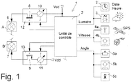
- the figure 1 shows in a simplified manner the various components of an active lighting device 1 portable or placed on a vehicle, which can for example be a bicycle.
- the lighting device 1 mainly comprises two optics referenced A and B.
- the first optic A comprises at least a first arrangement 6 of light sources
- the second optic B comprises at least a second arrangement 7 of light sources.
- the first arrangement 6 of light sources is provided for long-distance illumination and preferably with variable intensity.
- the second arrangement 7 of light sources is intended for illumination at a short distance and preferably at variable intensity.
- Each arrangement 6, 7 of light sources can comprise light-emitting diodes or groups of light-emitting diodes selectable by the control unit 2 or all activatable at the same time.
- at least three light sources can be provided by arrangement 6, 7 of light sources each capable of generating a light beam in the form of a cone having a different direction or axis of illumination.
- the orientation of the light beam is provided directly at the output of each light source or via one or more lenses. In this way, it is possible to select certain light sources by the control unit 2 if it is necessary to orient the average beam of light provided by each arrangement 6, 7 of activated light sources. This makes it possible to orient the average beam as a function of a turn made by the user of the vehicle.
- each arrangement 6, 7 of light sources can comprise an array of light sources, such as LED light-emitting diodes, which can be selected independently of one another or by groups of light-emitting diodes.
- the matrix can for example comprise x 2 light-emitting diodes, where x is an integer greater than or equal to 2. For example, one can provide 64 light-emitting diodes by arrangement 6, 7 of light sources.
- each optic A and B further comprises, in addition to the arrangements 6, 7 of light sources, an arrangement of lenses combined with the light sources, and mirrors, not shown, for the supply of a light beam of determined orientation.
- the light sources of the arrangements 6, 7 are controlled by a control unit 2 connected to a continuous power source Vdd.
- This electrical power source is preferably a DC voltage source, which comes from a rechargeable or primary battery, or which is extracted and rectified from received electromagnetic radiation.
- the lighting device 1 also comprises one or more sensors 3, 4a, 4b, 5a, 5b, 5c connected to the control unit 2 to allow the activation of each arrangement 6, 7 of light sources according to a measured parameter .
- the control unit 2 supplied by the DC voltage source Vdd, is arranged, as soon as the vehicle is used, to control the lighting of the light sources of the first and second arrangements 6, 7 of the first and second optics A, B automatically.
- the control unit 2 can also comprise a low frequency oscillator, which can be a clock or quartz crystal oscillator or MEMS, and at minus a volatile or non-volatile memory.
- the control unit 2 can be a microcontroller.
- the volatile or non-volatile memory not shown makes it possible to store measurements made by the sensor (s) and at least one calculation algorithm for managing and calculating the measurements made by the sensors 3, 4a, 4b, 5a, 5b, 5c.
- the lighting device 1 mainly comprises a light intensity sensor or light sensor 3, which can be composed of a solar cell or an array of solar cells. From a brightness threshold detected by the light intensity sensor 3, the control unit 2 controls the activation of at least certain light sources or groups of light sources of the first optic A and of the second optic B. This is done if the ambient light intensity is below a determined light threshold.
- the light intensity threshold can depend directly on the ambient light, where the vehicle in use is located.
- the light intensity of the activated light sources, or of the groups of activated light sources can be variable and normally inversely proportional to the change in intensity of the ambient light.
- certain light sources or groups of light sources of the second arrangement 7 of the second optic B are always activated as soon as the intensity of the ambient light is below the determined light intensity threshold, during use of the vehicle.
- certain light sources or groups of light sources of the first arrangement 6 of the first optic A are activated only if the intensity of the ambient light is insufficient and in addition with an additional condition as described below.
- a manual switch can also be provided so as to deactivate the lighting device with all the light sources.
- Said light sources can also be deactivated after a period of inactivity of the vehicle, that is to say after a determined time without movement, for example after 5 minutes.
- the lighting device 1 comprises at least one speed sensor 4a, 4b connected to the control unit 2.
- the speed sensor 4a, 4b determines the speed of the vehicle and, on exceeding a determined speed threshold, commands the activation of at least certain light sources or groups of light sources of the first arrangement 6 of the first optics A
- certain light sources or groups of light sources of the first arrangement 6 of the first optic A generate light, if the ambient light intensity detected by the light sensor 3 is less than the determined light threshold.
- the selected light sources of the second arrangement 7 of light sources are activated independently of the calculated vehicle speed, i.e. from the moment when the ambient light intensity detected by the light sensor 3 is below the determined light threshold.
- a manual switch makes it possible to deactivate the lighting device with all light sources. These light sources can also be deactivated after a determined time without movement, for example after 5 minutes.
- the speed sensor can be a GPS receiver or equivalent 4a or preferably a magnetic sensor 4b for picking up the passage of at least one permanent magnet placed on a spoke or the rim of a vehicle wheel.
- the lighting device 1 can further comprise or receive a calendar 3 ′ of the dates and times (ephemeris) of each month in the year of a place of use of the device, from which the ambient brightness is deemed insufficient.
- the control unit 2 can memorize this calendar 3 'of the determined place of use of the device to control the activation of the selected light sources of the optics A, B, if for example the determined speed threshold is also exceeded.
- This determined speed threshold can be set at 15 km / h or 25 km / h, but can be set to another value and stored.
- a first intensity variation block 12 which includes a set of first variators 10 connected to the supply voltage source Vdd. These first dimmers 10 are also each connected to first respective switches 8, which are themselves connected to the first arrangement 6 of light sources. Each first switch 8 is controlled by the control unit 2 to activate at least certain light sources of the first arrangement 6 of light sources, if at least the ambient light intensity is insufficient.
- a second intensity variation block 13 is provided and includes a set of second variators 11 connected to the supply voltage source Vdd. These second dimmers 11 are also each connected to respective second switches 9, which are themselves connected to the second arrangement 7 of light sources. Each second switch 9 is controlled by the control unit 2 to activate at least certain light sources of the second arrangement 7 of light sources, if at least the ambient light intensity is insufficient.
- the first and second switches 8, 9 of each intensity variation block 12, 13 are preferably MOS transistors, such as PMOS transistors as shown, but NMOS transistors can also be considered.
- the source of each first PMOS transistor 8 is connected to each respective first variator 10, while the source of each second PMOS transistor 9 is connected to each respective second variator 11.
- the gate of each first PMOS transistor 8 is connected to the control unit 2 to make it conductive or non-conductive.
- the gate of the second PMOS transistor 9 is connected to the control unit 2 to make it conductive or non-conductive.
- each dimmer 10, 11 can be a current source, the current of which intended to pass through each light source or group of light sources is variable and increases when the ambient light intensity decreases below the threshold. of determined light.
- the variation of the current of each variator is controlled directly by the control unit 2.
- the current sources can also be alternating current sources.
- the current in a dimmer 10, 11 may be different from a current in another dimmer 10, 11 depending on the control of the control unit 2. This makes it possible to modify the light intensity of a source of light or of a group of light sources with respect to another light source or another group of light sources. This makes it possible to ultimately generate, as a function of the selection of the light sources or the groups of light sources of each arrangement 6, 7 of light sources, to precisely orient the average light beam generated at the output of the optics A and B.
- the lighting device 1 comprises at least one orientation or tilt detector 5a, 5b, 5c connected to the control unit 2.
- the orientation or inclination detector 5a, 5b, 5c determines for example a curve made by the vehicle in use on a path or a road.
- the orientation or tilt detector 5a, 5b, 5c provides an orientation or tilt signal to the control unit 2 to select and adjust the light intensity of at least certain light sources. light or certain groups of light sources of the first arrangement 6 of light sources and / or of the second arrangement 7 of light sources.
- each light beam is different for the selected light sources or the selected groups of light sources, whether directly at the output of the light sources or the groups of light sources or by combination with a set of lenses .
- the average light beam of the selected light sources or the groups of selected light sources is directed to the right for a right turn or to the left for a left turn.
- the orientation or tilt detector can be composed of a potentiometer 5a and / or a magnetometer 5b and / or an inclinometer 5c and / or an accelerometer 5c and / or a gyrometer 5c as it will be further explained below with reference to figures 3a to 3c .
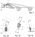
- the figure 2 schematically represents a vehicle 100 on a road 50 or a path with at least certain light sources activated from the two arrangements of light sources of the two optics A and B of the active lighting device 1. Both light source arrangements are activated, if the vehicle speed is above a threshold of determined speed and if the ambient light intensity is insufficient, otherwise only the second arrangement of light sources of optics B is activated.
- the light intensity I LUM (v, I AMB ) of the selected light sources of optics A depends on the speed v of the vehicle 100, which can be a bicycle, and on the ambient light intensity I AMB .
- the light intensity I LUM (I AMB ) of the selected light sources of optics B depends only on the ambient light intensity I AMB .
- the more the speed of the vehicle increases the more the average beam of light generated by the first arrangement of light sources of optics A increases in light intensity.
- certain light sources of optics A can be selected to orient the average beam of light of the first arrangement of light sources to illuminate even further up to a vertical azimuth, which tends towards 0.
- the light intensity light sources can normally vary in proportion to the inverse of the ambient light intensity, or even in stages.
- the Figures 3a, 3b, 3c schematically show a vehicle 100 on a road 50 or a path taking a turn to orient the average beam generated from selected light sources of the optics A and B of the active lighting device 1.
- Each optic A, B can be mounted for example on a handlebar of the bicycle 100.
- the orientation or inclination detectors are for example a magnetometer 5b or an inclinometer 5c or an accelerometer 5c or a gyrometer 5c or a potentiometer 5a or a combination of these detectors as previously mentioned.
- the orientation or tilt detector can be mounted on a support, such as a helmet of the user E of the vehicle 100 and to provide an orientation signal by two-way wireless communication to the control unit arranged on the handlebar of the vehicle 100. This makes it possible to control the orientation of the average beam generated by the selected light sources of the optics A and B by a movement of the head of the user E of the vehicle 100.
- the two arrangements of light sources of optics A and B of the lighting device 1 are activated.
- the average beam of light generated by the selected light sources must be oriented at an angle ⁇ according to the turn made on route 50.
- the control unit takes account of a rotation angle ⁇ of the front wheel D of the bicycle and also of the angular movement ⁇ of the head of the user E of the bicycle relative to the direction of the rear wheel F.
Abstract
Le dispositif (1) d'éclairage actif d'un véhicule comprend une première optique (A) avec un premier agencement (6) de sources de lumière pour une illumination à grande distance, qui sont contrôlée par une unité de contrôle (2), et une seconde optique (B) avec un second agencement (7) de sources de lumière pour une illumination à courte distance, qui sont contrôlées par l'unité de contrôle. Il comprend un capteur de lumière (3) pour déterminer l'intensité lumineuse d'un endroit où se situe le véhicule et permettre à l'unité de contrôle d'adapter l'intensité lumineuse des sources de lumière, si elles sont activées et si l'intensité de lumière ambiante est en dessous d'un seuil de lumière déterminé. De plus, il est prévu un capteur de vitesse (4a,4b) pour déterminer la vitesse du véhicule en utilisation sur un chemin, pour que l'unité de contrôle commande l'activation des sources de lumière du premier agencement de sources de lumière à partir d'au moins un seuil de vitesse déterminé. Il est aussi prévu un détecteur d'orientation ou d'inclinaison (5a,5b,5c) pour sélectionner et régler en intensité lumineuse au moins certaines sources de lumière ou certains groupes de sources de lumière des premier et second agencements de sources de lumière.The device (1) for active lighting of a vehicle comprises a first optic (A) with a first arrangement (6) of light sources for long-distance illumination, which are controlled by a control unit (2), and a second optic (B) with a second arrangement (7) of light sources for short-distance illumination, which are controlled by the control unit. It includes a light sensor (3) to determine the light intensity of a place where the vehicle is located and allow the control unit to adjust the light intensity of the light sources, if they are activated and if the ambient light intensity is below a determined light threshold. In addition, a speed sensor (4a, 4b) is provided for determining the speed of the vehicle in use on a path, so that the control unit controls the activation of the light sources from the first arrangement of light sources to from at least a certain speed threshold. An orientation or tilt detector (5a, 5b, 5c) is also provided for selecting and adjusting in light intensity at least certain light sources or certain groups of light sources of the first and second arrangements of light sources.
Description
L'invention concerne un dispositif d'éclairage actif portable ou placé sur un véhicule à au moins une roue, tel qu'un vélo. De préférence, chaque dispositif d'éclairage dispose d'une première optique à au moins un premier agencement de sources de lumière, et d'une seconde optique à au moins un second agencement de sources de lumière, qui sont placés sur le véhicule.The invention relates to an active lighting device portable or placed on a vehicle with at least one wheel, such as a bicycle. Preferably, each lighting device has a first optic with at least a first arrangement of light sources, and a second optic with at least a second arrangement of light sources, which are placed on the vehicle.
Pour éclairer de manière adéquate un chemin ou une route empruntée par un véhicule, il est connu d'utiliser un dispositif d'éclairage ayant un réglage adapté de l'intensité de la lumière générée de phares ou d'autres sources de lumière. Un tel dispositif d'éclairage peut aussi être adapté pour orienter le faisceau de lumière en fonction des virages à effectuer dans l'obscurité ou pour éviter d'éblouir un conducteur d'un véhicule à croiser sur la route.To adequately illuminate a path or a road taken by a vehicle, it is known to use a lighting device having a suitable adjustment of the intensity of the light generated from headlights or other light sources. Such a lighting device can also be adapted to orient the light beam according to the turns to be made in the dark or to avoid dazzling a driver of a vehicle to be encountered on the road.
La demande de brevet
La demande de brevet
Le brevet
Il est également connu par le brevet
L'invention a donc pour but de pallier les inconvénients cités ci-dessus pour réaliser un dispositif d'éclairage actif portable ou placé sur un véhicule à au moins une roue facile d'utilisation et sans complication pour permettre un bon éclairage tenant compte de la vitesse ou de l'inclinaison du véhicule.The invention therefore aims to overcome the drawbacks mentioned above to achieve an active lighting device portable or placed on a vehicle with at least one wheel easy to use and uncomplicated to allow good lighting taking into account the vehicle speed or tilt.
A cet effet, l'invention concerne un dispositif d'éclairage actif portable ou placé sur un véhicule à au moins une roue, qui comprend les caractéristiques des revendications indépendantes 1 ou 2.To this end, the invention relates to an active lighting device portable or placed on a vehicle with at least one wheel, which comprises the features of
Des formes d'exécution particulières du dispositif d'éclairage sont définies dans les revendications dépendantes 3 à 13.Particular embodiments of the lighting device are defined in
Un avantage du dispositif d'éclairage selon l'invention réside dans le fait qu'un capteur de lumière du dispositif détecte l'intensité de la lumière ambiante de manière à activer des sources de lumière ou des groupes de sources de lumière des optiques A et B, si l'intensité de lumière ambiante est en dessous d'un seuil de lumière déterminé. L'activation des sources de lumière ou groupes de sources de lumière peut se faire de manière automatique sur commande d'une unité de contrôle alimentée par une source de tension d'alimentation, telle qu'une batterie.An advantage of the lighting device according to the invention lies in the fact that a light sensor of the device detects the intensity of the ambient light so as to activate light sources or groups of light sources of optics A and B, if the ambient light intensity is below a determined light threshold. The activation of the light sources or groups of light sources can be done automatically on command of a control unit supplied by a supply voltage source, such as a battery.
Avantageusement, l'intensité de lumière des sources de lumière activées ou groupes de sources de lumière activées est gérée par l'unité de contrôle normalement inversement proportionnelle à l'intensité de la lumière ambiante.Advantageously, the light intensity of the activated light sources or groups of activated light sources is managed by the control unit normally inversely proportional to the intensity of the ambient light.
Avantageusement, un capteur de vitesse est prévu dans le dispositif d'éclairage pour activer des sources de lumière ou des groupes de sources de lumière de l'optique A uniquement si une vitesse du véhicule en utilisation dépasse un seuil de vitesse déterminé. Des sources de lumière ou des groupes de sources de lumière de l'optique B peuvent être activées dès que l'intensité de lumière ambiante est en dessous du seuil de lumière déterminé, et ceci indépendamment de la vitesse du véhicule.Advantageously, a speed sensor is provided in the lighting device for activating light sources or groups of light sources of optics A only if a speed of the vehicle in use exceeds a determined speed threshold. Light sources or groups of light sources of optics B can be activated as soon as the ambient light intensity is below the determined light threshold, and this independently of the vehicle speed.
Avantageusement, au moins un détecteur d'orientation ou d'inclinaison peut aussi être prévu dans le dispositif d'éclairage pour sélectionner et régler en intensité lumineuse au moins certaines sources de lumière ou certains groupes de sources de lumière du premier agencement de sources de lumière et/ou du second agencement de sources de lumière. L'éclairage des sources de lumière ou groupes de sources de lumière sélectionnés, éventuellement en combinaison avec un jeu de lentilles, permet d'orienter le faisceau de lumière résultant provenant de chaque agencement de sources de lumière dans une direction fonction du virage effectué sur une route ou un chemin.Advantageously, at least one orientation or tilt detector can also be provided in the lighting device for selecting and adjusting in light intensity at least certain light sources or certain groups of light sources of the first arrangement of light sources. and / or the second arrangement of light sources. The illumination of the selected light sources or groups of light sources, possibly in combination with a set of lenses, makes it possible to orient the resulting light beam coming from each arrangement of light sources in a direction depending on the turn made on a road or path.
Les buts, avantages et caractéristiques d'un dispositif d'éclairage actif portable ou placé sur un véhicule à au moins une roue, apparaîtront mieux dans la description suivante sur la base d'au moins une forme d'exécution non limitative illustrée par les dessins sur lesquels :
- la
figure 1 représente un schéma bloc simplifié des composants du dispositif d'éclairage actif selon l'invention, - la
figure 2 représente schématiquement un véhicule sur une route ou un chemin avec les sources de lumière activées des deux optiques A et B du dispositif d'éclairage actif en tenant compte de l'intensité de lumière et de la vitesse mesurée pour sélectionner et régler en intensité lumineuse au moins certaines sources de lumière ou certains groupes de sources de lumière de l'optique A selon l'invention, et - les
figures 3a, 3b et 3c montrent schématiquement un véhicule sur une route ou un chemin prenant un virage pour sélectionner et régler en intensité lumineuse au moins certaines sources de lumière ou certains groupes de sources de lumière des optiques A et B du dispositif d'éclairage actif selon l'invention.
- the
figure 1 represents a simplified block diagram of the components of the active lighting device according to the invention, - the
figure 2 schematically represents a vehicle on a road or path with the light sources activated by the two optics A and B of the active lighting device, taking into account the light intensity and the measured speed to select and adjust the light intensity at minus certain light sources or certain groups of light sources of optics A according to the invention, and - the
Figures 3a, 3b and 3c schematically show a vehicle on a road or path taking a turn to select and adjust in light intensity at least certain light sources or certain groups of light sources of the optics A and B of the active lighting device according to the invention.
Dans la description suivante, il est fait référence à un dispositif d'éclairage actif portable ou placé sur un véhicule à au moins une roue. Tous les composants électroniques, qui sont bien connus d'un homme du métier dans ce domaine technique, ne sont décrits que de manière simplifiée. Le véhicule peut être par exemple un vélo à deux roues de manière à être mis en mouvement par un utilisateur sur un chemin, par exemple sur un chemin routier ou en forêt.In the following description, reference is made to an active lighting device portable or placed on a vehicle with at least one wheel. All the electronic components, which are well known to a person skilled in the art in this technical field, are described only in a simplified manner. The vehicle may for example be a two-wheeled bicycle so as to be set in motion by a user on a path, for example on a road or in the forest.
La
Chaque agencement 6, 7 de sources de lumière peut comprendre des diodes électroluminescentes ou des groupes de diodes électroluminescentes sélectionnables par l'unité de contrôle 2 ou toutes activables en même temps. Il peut être compté au moins deux sources de lumière par agencement 6, 7 de sources de lumière. De préférence, il peut être prévu au moins trois sources de lumière par agencement 6, 7 de sources de lumière susceptibles chacune de générer un faisceau lumineux sous la forme d'un cône ayant une direction ou axe d'illumination différent. L'orientation du faisceau lumineux est fournie directement en sortie de chaque source de lumière ou par l'intermédiaire d'une ou plusieurs lentilles. De cette manière, il peut être sélectionné certaines sources de lumière par l'unité de contrôle 2 s'il faut orienter le faisceau moyen de lumière fourni par chaque agencement 6, 7 de sources de lumière activé. Ceci permet d'orienter le faisceau moyen en fonction d'un virage effectué par l'utilisateur du véhicule.Each
Il est à noter encore que chaque agencement 6, 7 de sources de lumière peut comprendre une matrice de sources de lumière, telles que des diodes électroluminescentes LED, qui peuvent être sélectionnées indépendamment l'une de l'autre ou par groupes de diodes électroluminescentes. La matrice peut par exemple comprendre x2 diodes électroluminescentes, où x est un nombre entier supérieur ou égal à 2. Par exemple, on peut prévoir 64 diodes électroluminescentes par agencement 6, 7 de sources de lumière.It should also be noted that each
Généralement, chaque optique A et B comprend encore en plus des agencements 6, 7 de sources de lumière, un agencement de lentilles combinées aux sources de lumière, et miroirs non représenté pour la fourniture d'un faisceau de lumière d'orientation déterminée. Dans le cas de figure représenté à la
Le dispositif 1 d'éclairage comprend encore un ou plusieurs capteurs 3, 4a, 4b, 5a, 5b, 5c reliés à l'unité de contrôle 2 pour permettre l'activation de chaque agencement 6, 7 de sources de lumière selon un paramètre mesuré. De préférence, l'unité de contrôle 2, alimentée par la source de tension continue Vdd, est agencée, dès l'utilisation du véhicule, pour contrôler l'éclairage des sources de lumière des premier et second agencements 6, 7 des première et seconde optiques A, B de manière automatique.The
L'unité de contrôle 2 peut comprendre encore un oscillateur à basse fréquence, qui peut être un oscillateur à quartz horloger ou MEMS, et au moins une mémoire volatile ou non volatile. Ainsi, l'unité de contrôle 2 peut être un microcontrôleur. La mémoire volatile ou non volatile non représentée permet de mémoriser des mesures effectuées par le ou les capteurs et au moins un algorithme de calcul pour la gestion et les calculs des mesures effectuées par les capteurs 3, 4a, 4b, 5a, 5b, 5c.The
Le dispositif 1 d'éclairage comprend principalement un capteur d'intensité lumineuse ou capteur de lumière 3, qui peut être composé d'une cellule solaire ou d'un réseau de cellules solaires. A partir d'un seuil de luminosité détecté par le capteur d'intensité lumineuse 3, l'unité de contrôle 2 commande l'activation d'au moins certaines sources de lumière ou des groupes de sources de lumière de la première optique A et de la seconde optique B. Ceci est effectué si l'intensité de lumière ambiante est en dessous d'un seuil de lumière déterminé. Le seuil d'intensité lumineuse peut dépendre directement de la luminosité ambiante, où se situe le véhicule en utilisation. De plus, l'intensité lumineuse des sources de lumière activées, ou des groupes de sources de lumière activées peut être variable et normalement inversement proportionnelle au changement d'intensité de la luminosité ambiante.The
Il est à noter que certaines sources de lumière ou des groupes de sources de lumière du second agencement 7 de la seconde optique B sont toujours activées dès que l'intensité de la lumière ambiante est en dessous du seuil d'intensité lumineuse déterminé, lors de l'utilisation du véhicule. Par contre, certaines sources de lumière ou des groupes de sources de lumière du premier agencement 6 de la première optique A sont activées seulement si l'intensité de la lumière ambiante est insuffisante et en plus avec une condition supplémentaire comme décrit ci-dessous.It should be noted that certain light sources or groups of light sources of the
Bien entendu, lorsque le véhicule n'est plus en utilisation, il peut aussi être prévu un interrupteur manuel de manière à désactiver le dispositif d'éclairage avec toutes les sources de lumière. Lesdites sources de lumière peuvent être aussi désactivées après une période d'inutilisation du véhicule, c'est-à-dire après un temps déterminé sans mouvement par exemple après 5 minutes.Of course, when the vehicle is no longer in use, a manual switch can also be provided so as to deactivate the lighting device with all the light sources. Said light sources can also be deactivated after a period of inactivity of the vehicle, that is to say after a determined time without movement, for example after 5 minutes.
Dans une première variante de forme d'exécution du dispositif 1, le dispositif 1 d'éclairage comprend au moins un capteur de vitesse 4a, 4b relié à l'unité de contrôle 2. Lors de l'utilisation du véhicule, le capteur de vitesse 4a, 4b détermine la vitesse du véhicule et, à partir du dépassement d'un seuil de vitesse déterminé, commande l'activation d'au moins certaines sources de lumière ou des groupes de sources de lumière du premier agencement 6 de la première optique A. De plus, certaines sources de lumière ou des groupes de sources de lumière du premier agencement 6 de la première optique A génèrent de la lumière, si l'intensité de lumière ambiante détectée par le capteur de lumière 3 est inférieure au seuil de lumière déterminé. Comme susmentionné, les sources de lumière sélectionnées du second agencement 7 de sources de lumière sont activées indépendamment de la vitesse du véhicule calculée, c'est-à-dire dès le moment où l'intensité de lumière ambiante détectée par le capteur de lumière 3 est inférieure au seuil de lumière déterminé.In a first alternative embodiment of the
Comme indiqué ci-dessus, lorsque le véhicule n'est plus en utilisation, un interrupteur manuel permet de désactiver le dispositif d'éclairage avec toutes les sources de lumière. Ces sources de lumière peuvent être aussi désactivées après un temps déterminé sans mouvement par exemple après 5 minutes.As indicated above, when the vehicle is no longer in use, a manual switch makes it possible to deactivate the lighting device with all light sources. These light sources can also be deactivated after a determined time without movement, for example after 5 minutes.
Le capteur de vitesse peut être un récepteur GPS ou équivalent 4a ou de préférence un capteur magnétique 4b pour capter le passage d'au moins un aimant permanent disposé sur un rayon ou la jante d'une roue du véhicule. Chaque impulsion magnétique de passage de l'aimant permanent à proximité du capteur magnétique 4b, et selon une cadence dans le temps générée par l'oscillateur basse fréquence, permet à l'unité de contrôle 2 de calculer la vitesse et le moment du dépassement du seuil de vitesse déterminé.The speed sensor can be a GPS receiver or equivalent 4a or preferably a magnetic sensor 4b for picking up the passage of at least one permanent magnet placed on a spoke or the rim of a vehicle wheel. Each magnetic pulse of passage of the permanent magnet near the magnetic sensor 4b, and according to a cadence in time generated by the low frequency oscillator, allows the
Le dispositif 1 d'éclairage peut comprendre encore ou recevoir un calendrier 3' des dates et heures (éphémérides) de chaque mois dans l'année d'un lieu d'utilisation du dispositif, à partir de laquelle la luminosité ambiante est jugée insuffisante. L'unité de contrôle 2 peut mémoriser ce calendrier 3' du lieu déterminé d'utilisation du dispositif pour contrôler l'activation des sources de lumière sélectionnées des optiques A, B, si par exemple le seuil de vitesse déterminé est aussi dépassé. Ce seuil de vitesse déterminé peut être fixé à 15 km/h ou 25 km/h, mais peut être défini à une autre valeur et mémorisé.The
Il est aussi possible selon l'emplacement, de faire varier les seuils d'activation selon que le véhicule est dans une plaine ouverte ou dans une vallée étroite, où la lumière ambiante est plus rapidement faible.Depending on the location, it is also possible to vary the activation thresholds depending on whether the vehicle is in an open plain or in a narrow valley, where the ambient light is more rapidly dim.
Pour ce faire, il est prévu un premier bloc de variation d'intensité 12, qui comprend un ensemble de premiers variateurs 10 connectés à la source de tension d'alimentation Vdd. Ces premiers variateurs 10 sont encore reliés chacun à des premiers interrupteurs 8 respectifs, qui sont eux-mêmes reliés au premier agencement 6 de sources de lumière. Chaque premier interrupteur 8 est commandé par l'unité de contrôle 2 pour activer au moins certaines sources de lumière du premier agencement 6 de sources de lumière, si au moins l'intensité de lumière ambiante est insuffisante. Un second bloc de variation d'intensité 13 est prévu et comprend un ensemble de seconds variateurs 11 connectés à la source de tension d'alimentation Vdd. Ces seconds variateurs 11 sont encore reliés chacun à des seconds interrupteurs 9 respectifs, qui sont eux-mêmes reliés au second agencement 7 de sources de lumière. Chaque second interrupteur 9 est commandé par l'unité de contrôle 2 pour activer au moins certaines sources de lumière du second agencement 7 de sources de lumière, si au moins l'intensité de lumière ambiante est insuffisante.To do this, a first
Les premiers et seconds interrupteurs 8, 9 de chaque bloc de variation d'intensité 12, 13 sont de préférence des transistors MOS, tels que des transistors PMOS comme représentés, mais des transistors NMOS peuvent aussi être envisagés. La source de chaque premier transistor PMOS 8 est reliée à chaque premier variateur 10 respectif, alors que la source de chaque second transistor PMOS 9 est reliée à chaque second variateur 11 respectif. La grille de chaque premier transistor PMOS 8 est reliée à l'unité de contrôle 2 pour le rendre conducteur ou non conducteur. La grille du second transistor PMOS 9 est reliée à l'unité de contrôle 2 pour le rendre conducteur ou non conducteur.The first and
Il est à noter que chaque variateur 10, 11 peut être une source de courant, dont le courant prévu pour passer dans chaque source de lumière ou groupe de sources de lumière est variable et augmente quand l'intensité de lumière ambiante diminue en dessous du seuil de lumière déterminé. La variation du courant de chaque variateur est contrôlée directement par l'unité de contrôle 2. Les sources de courant peuvent aussi être des sources à courant alternatif.It should be noted that each dimmer 10, 11 can be a current source, the current of which intended to pass through each light source or group of light sources is variable and increases when the ambient light intensity decreases below the threshold. of determined light. The variation of the current of each variator is controlled directly by the
Il est à noter que le courant dans un variateur 10, 11 peut être différent d'un courant dans un autre variateur 10, 11 selon la commande de l'unité de contrôle 2. Cela permet de modifier l'intensité lumineuse d'une source de lumière ou d'un groupe de sources de lumière par rapport à une autre source de lumière ou un autre groupe de sources de lumière. Ceci permet de générer au final en fonction de la sélection des sources de lumière ou des groupes de sources de lumière de chaque agencement 6, 7 de sources de lumière d'orienter précisément le faisceau lumineux moyen généré en sortie des optiques A et B.It should be noted that the current in a dimmer 10, 11 may be different from a current in another dimmer 10, 11 depending on the control of the
Dans une seconde variante de forme d'exécution du dispositif 1, le dispositif 1 d'éclairage comprend au moins un détecteur d'orientation ou d'inclinaison 5a, 5b, 5c relié à l'unité de contrôle 2. Lors de l'utilisation du véhicule, le détecteur d'orientation ou d'inclinaison 5a, 5b, 5c détermine par exemple une courbe effectuée par le véhicule en utilisation sur un chemin ou une route. Le détecteur d'orientation ou d'inclinaison 5a, 5b, 5c fournit un signal d'orientation ou d'inclinaison à l'unité de contrôle 2 pour sélectionner et régler en intensité lumineuse au moins certaines sources de lumière ou certains groupes de sources de lumière du premier agencement 6 de sources de lumière et/ou du second agencement 7 de sources de lumière. L'orientation de chaque faisceau de lumière est différente pour les sources de lumière sélectionnées ou les groupes de sources de lumière sélectionnées, que ce soit directement en sortie des sources de lumière ou des groupes de sources de lumière ou par combinaison avec un jeu de lentilles. Ainsi en fonction d'un virage effectué, le faisceau moyen de lumière des sources de lumière sélectionnées ou les groupes de sources de lumière sélectionnées est dirigé vers la droite pour un virage à droite ou vers la gauche pour un virage à gauche.In a second variant embodiment of the
Aucune motorisation n'est donc nécessaire pour l'orientation des faisceaux de lumière des sources de lumière sélectionnées pour permettre d'orienter le faisceau moyen généré par chaque agencement 6, 7 de sources de lumière en fonction du virage ou courbe à effectuer avec le véhicule.No motorization is therefore necessary for the orientation of the light beams of the selected light sources to enable the average beam generated by each
On peut imaginer dans cette seconde variante d'avoir les deux agencements 6, 7 de sources de lumière activés dès que l'intensité de la lumière ambiante est en dessous d'un seuil de lumière déterminé. Cependant il peut aussi être prévu d'activer uniquement certaines sources de lumière ou groupes de sources de lumière du second agencement 7 de sources de lumière, si la vitesse détectée par le capteur de vitesse 4a, 4b ne dépasse pas le seuil de vitesse déterminé.One can imagine in this second variant to have the two
Le détecteur d'orientation ou d'inclinaison peut être composé d'un potentiomètre 5a et/ou d'un magnétomètre 5b et/ou d'un inclinomètre 5c et/ou d'un accéléromètre 5c et/ou d'un gyromètre 5c comme il sera encore expliqué ci-après en référence aux
La
Comme montré à la
Les
Le détecteur d'orientation ou d'inclinaison peut être monté sur un support, tel qu'un casque de l'utilisateur E du véhicule 100 et pour fournir un signal d'orientation par une communication bidirectionnelle sans fil à l'unité de contrôle disposée sur le guidon du véhicule 100. Ceci permet de contrôler l'orientation du faisceau moyen généré par les sources de lumière sélectionnées des optiques A et B par un mouvement de la tête de l'utilisateur E du véhicule 100.The orientation or tilt detector can be mounted on a support, such as a helmet of the user E of the
A la
A la
A la
A partir de la description qui vient d'être faite, plusieurs variantes de réalisation d'un dispositif d'éclairage actif portable ou placé sur un véhicule à au moins une roue sont possibles sans sortir du cadre de l'invention définie par les revendications suivantes.From the description which has just been made, several alternative embodiments of an active lighting device portable or placed on a vehicle with at least one wheel are possible without departing from the scope of the invention defined by the following claims .
Claims (13)
caractérisé en ce que le dispositif comprend :
characterized in that the device comprises:
caractérisé en ce que le dispositif comprend :
characterized in that the device comprises:
Priority Applications (5)
| Application Number | Priority Date | Filing Date | Title |
|---|---|---|---|
| EP18191095.1A EP3617048A1 (en) | 2018-08-28 | 2018-08-28 | Portable or vehicle-mounted active lighting device |
| EP19184748.2A EP3617049A1 (en) | 2018-08-28 | 2019-07-05 | Bicycle-mounted active lighting device device |
| US16/509,690 US10532786B1 (en) | 2018-08-28 | 2019-07-12 | Portable active lighting device or same installed on a bicycle |
| JP2019148343A JP6905013B2 (en) | 2018-08-28 | 2019-08-13 | An active lighting device that can be carried or installed on a bicycle |
| CN201910781647.5A CN110861737A (en) | 2018-08-28 | 2019-08-23 | Portable active lighting device or such a device mounted on a bicycle |
Applications Claiming Priority (1)
| Application Number | Priority Date | Filing Date | Title |
|---|---|---|---|
| EP18191095.1A EP3617048A1 (en) | 2018-08-28 | 2018-08-28 | Portable or vehicle-mounted active lighting device |
Publications (1)
| Publication Number | Publication Date |
|---|---|
| EP3617048A1 true EP3617048A1 (en) | 2020-03-04 |
Family
ID=63490215
Family Applications (2)
| Application Number | Title | Priority Date | Filing Date |
|---|---|---|---|
| EP18191095.1A Withdrawn EP3617048A1 (en) | 2018-08-28 | 2018-08-28 | Portable or vehicle-mounted active lighting device |
| EP19184748.2A Pending EP3617049A1 (en) | 2018-08-28 | 2019-07-05 | Bicycle-mounted active lighting device device |
Family Applications After (1)
| Application Number | Title | Priority Date | Filing Date |
|---|---|---|---|
| EP19184748.2A Pending EP3617049A1 (en) | 2018-08-28 | 2019-07-05 | Bicycle-mounted active lighting device device |
Country Status (4)
| Country | Link |
|---|---|
| US (1) | US10532786B1 (en) |
| EP (2) | EP3617048A1 (en) |
| JP (1) | JP6905013B2 (en) |
| CN (1) | CN110861737A (en) |
Families Citing this family (3)
| Publication number | Priority date | Publication date | Assignee | Title |
|---|---|---|---|---|
| US20190144062A1 (en) * | 2017-11-13 | 2019-05-16 | Wayne Gerard Poole | Illuminable display responsive to motions of a host vehicle |
| US11643160B2 (en) | 2020-12-29 | 2023-05-09 | Southern California Design Company | Accessory mounting system |
| JP2023128615A (en) * | 2022-03-04 | 2023-09-14 | スタンレー電気株式会社 | Lighting device for bicycle |
Citations (8)
| Publication number | Priority date | Publication date | Assignee | Title |
|---|---|---|---|---|
| EP0699559A2 (en) * | 1994-09-02 | 1996-03-06 | Ante Josic | Automatic lighting control system for vehicle |
| GB2358914A (en) * | 2000-02-04 | 2001-08-08 | Koito Mfg Co Ltd | Steering angle dependent lighting system for vehicles |
| FR2844759B1 (en) | 2002-09-20 | 2007-04-06 | Ecole Nationale D Ingenieurs D | GYROSTABLE HEADLIGHT FOR MOTORCYCLE |
| EP2420408A1 (en) * | 2000-03-20 | 2012-02-22 | Gentex Corporation | System for controlling exterior vehicle lights |
| DE102015225890A1 (en) * | 2014-12-25 | 2016-06-30 | Koito Manufacturing Co., Ltd. | vehicle light |
| WO2017023293A1 (en) | 2015-08-03 | 2017-02-09 | Ford Global Technologies, Llc | Intelligent bicycle lighting system for optimal road visibility |
| US20180020528A1 (en) | 2016-07-13 | 2018-01-18 | Yam Ho Yeung | Smart lighting system and method |
| EP3036149B1 (en) | 2013-08-21 | 2018-04-11 | Mcaleese, William Philip | Lighting device for a bicycle |
Family Cites Families (20)
| Publication number | Priority date | Publication date | Assignee | Title |
|---|---|---|---|---|
| JPH02121009A (en) * | 1988-10-31 | 1990-05-08 | Suzuki Motor Co Ltd | Device to control direction of object to be controlled according to posture of driver |
| JP3014253B2 (en) * | 1993-09-17 | 2000-02-28 | 株式会社ミツバ | Bicycle headlight device |
| JPH07329851A (en) * | 1994-06-03 | 1995-12-19 | Sharp Corp | Automatic lighting and illuminating device for bicycle |
| US6891563B2 (en) * | 1996-05-22 | 2005-05-10 | Donnelly Corporation | Vehicular vision system |
| US6611610B1 (en) * | 1997-04-02 | 2003-08-26 | Gentex Corporation | Vehicle lamp control |
| JP2001219881A (en) * | 2000-02-09 | 2001-08-14 | Yamaha Motor Co Ltd | Control device for saddle riding vehicle |
| JP3619850B2 (en) * | 2002-04-08 | 2005-02-16 | 株式会社キャットアイ | Bicycle headlamp |
| JP2007145233A (en) * | 2005-11-29 | 2007-06-14 | Denso Corp | Light irradiation system |
| JP4656429B2 (en) * | 2006-06-02 | 2011-03-23 | 株式会社デンソー | Headlight control system |
| US20100123402A1 (en) * | 2008-11-19 | 2010-05-20 | Yi-Lun Chen | Bicycle control device |
| JP2011201382A (en) * | 2010-03-25 | 2011-10-13 | Mitsuba Corp | Headlight for bicycle |
| JP2013193562A (en) * | 2012-03-19 | 2013-09-30 | Yamaha Motor Co Ltd | Sub-headlight unit and sub-headlight system for vehicle turning in lean attitude, and vehicle turning in lean attitude |
| CN202593696U (en) * | 2012-05-23 | 2012-12-12 | 成贯企业有限公司 | Bicycle lamp with function of manually and automatically adjusting lighting distance |
| EP2747522A1 (en) * | 2012-12-20 | 2014-06-25 | Universite De Liege | Street lighting control, method, device and system |
| CN105501336A (en) * | 2014-10-14 | 2016-04-20 | 李文嵩 | Intelligent lamp device for bicycles and motorcycles |
| US9260148B1 (en) * | 2014-11-24 | 2016-02-16 | Wen-Sung Lee | Light unit for bicycle/motorbike |
| CN205716835U (en) * | 2016-02-18 | 2016-11-23 | 李文杰 | A kind of dynamo lighting set |
| CN107202289A (en) * | 2016-03-18 | 2017-09-26 | 技嘉科技股份有限公司 | Lighting headlamp unit and its control method |
| JP6745620B2 (en) * | 2016-03-23 | 2020-08-26 | 株式会社小糸製作所 | Headlamps for motorcycles |
| JP2018062260A (en) * | 2016-10-13 | 2018-04-19 | ボッシュ株式会社 | Bicycle lighting unit and bicycle |
-
2018
- 2018-08-28 EP EP18191095.1A patent/EP3617048A1/en not_active Withdrawn
-
2019
- 2019-07-05 EP EP19184748.2A patent/EP3617049A1/en active Pending
- 2019-07-12 US US16/509,690 patent/US10532786B1/en active Active
- 2019-08-13 JP JP2019148343A patent/JP6905013B2/en active Active
- 2019-08-23 CN CN201910781647.5A patent/CN110861737A/en active Pending
Patent Citations (8)
| Publication number | Priority date | Publication date | Assignee | Title |
|---|---|---|---|---|
| EP0699559A2 (en) * | 1994-09-02 | 1996-03-06 | Ante Josic | Automatic lighting control system for vehicle |
| GB2358914A (en) * | 2000-02-04 | 2001-08-08 | Koito Mfg Co Ltd | Steering angle dependent lighting system for vehicles |
| EP2420408A1 (en) * | 2000-03-20 | 2012-02-22 | Gentex Corporation | System for controlling exterior vehicle lights |
| FR2844759B1 (en) | 2002-09-20 | 2007-04-06 | Ecole Nationale D Ingenieurs D | GYROSTABLE HEADLIGHT FOR MOTORCYCLE |
| EP3036149B1 (en) | 2013-08-21 | 2018-04-11 | Mcaleese, William Philip | Lighting device for a bicycle |
| DE102015225890A1 (en) * | 2014-12-25 | 2016-06-30 | Koito Manufacturing Co., Ltd. | vehicle light |
| WO2017023293A1 (en) | 2015-08-03 | 2017-02-09 | Ford Global Technologies, Llc | Intelligent bicycle lighting system for optimal road visibility |
| US20180020528A1 (en) | 2016-07-13 | 2018-01-18 | Yam Ho Yeung | Smart lighting system and method |
Also Published As
| Publication number | Publication date |
|---|---|
| EP3617049A1 (en) | 2020-03-04 |
| US10532786B1 (en) | 2020-01-14 |
| JP2020033007A (en) | 2020-03-05 |
| JP6905013B2 (en) | 2021-07-21 |
| CN110861737A (en) | 2020-03-06 |
Similar Documents
| Publication | Publication Date | Title |
|---|---|---|
| EP3617049A1 (en) | Bicycle-mounted active lighting device device | |
| FR2860465A1 (en) | DEVICE FOR IMPROVING VISION CONDITIONS IN A VEHICLE | |
| FR2893907A1 (en) | Electrical movable support for e.g. portable, self-contained light vehicle, has motorization maintaining wheel in line with center of gravity, and steering electronic controlled linearly by longitudinal accelerometer integrated to fork | |
| WO2017109318A1 (en) | Anticipative electric mower and method of piloting such a mower | |
| EP3616991A1 (en) | Bicycle-mounted active lighting device device | |
| EP3320387B1 (en) | Range-based control of the transmission of a variable transmission lens | |
| EP2830900A2 (en) | Device for nighttime motor vehicle driving assistance | |
| FR2867119A1 (en) | DEVICE FOR AUTOMATICALLY ADJUSTING THE BEAM AXIS OF A VEHICLE HEADLIGHT | |
| FR2840541A1 (en) | MOTORIZED REMOTE CONTROLLED MOBILE TOY | |
| EP1388460A2 (en) | Control device for automatic adjustment of the position of an automobile headlamp | |
| CH715275A2 (en) | Active lighting device portable or placed on a bicycle. | |
| FR3013278A1 (en) | DEVICE FOR CONTROLLING THE VEHICLE LAMP | |
| CH715274A2 (en) | Active lighting device portable or placed on a bicycle. | |
| FR2802157A1 (en) | APPARATUS FOR ADJUSTING THE DIRECTION OF LIGHTING OF A VEHICLE HEADLIGHT | |
| EP1540372B1 (en) | Device for detecting the crossing of a road marking for motor vehicle | |
| FR2988052A1 (en) | Method for adapting e.g. brightness of illuminating or signaling light source of car, involves determining brightness value of light source, and adjusting brightness value in order to reach value of determined characteristic brightness | |
| EP0659610B1 (en) | Autoadaptive adjusting device for rear view mirror with electrical control | |
| WO2020193107A1 (en) | Method and system for measuring at least one physical parameter for a bicycle | |
| EP3817972A1 (en) | Control system for a hybrid bicycle, and hybrid bicycle equipped with such a control system | |
| FR3084050A1 (en) | ADAPTIVE LIGHTING DEVICE FOR CYCLES | |
| EP3575802B1 (en) | Method and system for measuring speed and/or a distance travelled by a bicycle | |
| CH716005A2 (en) | Method and system for measuring at least one physical parameter for a bicycle. | |
| FR3042449A1 (en) | DEVICE AND METHOD FOR MANAGING THE ELECTRIC MOTORIZATION MEANS OF AN ELECTRICALLY ASSISTED VEHICLE | |
| EP1490245A2 (en) | Signalling device for collision prevention | |
| FR2632464A1 (en) | Electronic lighting device for bicycles and wheelchairs |
Legal Events
| Date | Code | Title | Description |
|---|---|---|---|
| PUAI | Public reference made under article 153(3) epc to a published international application that has entered the european phase |
Free format text: ORIGINAL CODE: 0009012 |
|
| STAA | Information on the status of an ep patent application or granted ep patent |
Free format text: STATUS: THE APPLICATION HAS BEEN PUBLISHED |
|
| AK | Designated contracting states |
Kind code of ref document: A1 Designated state(s): AL AT BE BG CH CY CZ DE DK EE ES FI FR GB GR HR HU IE IS IT LI LT LU LV MC MK MT NL NO PL PT RO RS SE SI SK SM TR |
|
| AX | Request for extension of the european patent |
Extension state: BA ME |
|
| STAA | Information on the status of an ep patent application or granted ep patent |
Free format text: STATUS: THE APPLICATION IS DEEMED TO BE WITHDRAWN |
|
| 18D | Application deemed to be withdrawn |
Effective date: 20200905 |