EP3616991A1 - Bicycle-mounted active lighting device device - Google Patents
Bicycle-mounted active lighting device device Download PDFInfo
- Publication number
- EP3616991A1 EP3616991A1 EP19184419.0A EP19184419A EP3616991A1 EP 3616991 A1 EP3616991 A1 EP 3616991A1 EP 19184419 A EP19184419 A EP 19184419A EP 3616991 A1 EP3616991 A1 EP 3616991A1
- Authority
- EP
- European Patent Office
- Prior art keywords
- light
- light source
- optic
- bicycle
- control unit
- Prior art date
- Legal status (The legal status is an assumption and is not a legal conclusion. Google has not performed a legal analysis and makes no representation as to the accuracy of the status listed.)
- Pending
Links
Images


Classifications
-
- B—PERFORMING OPERATIONS; TRANSPORTING
- B60—VEHICLES IN GENERAL
- B60Q—ARRANGEMENT OF SIGNALLING OR LIGHTING DEVICES, THE MOUNTING OR SUPPORTING THEREOF OR CIRCUITS THEREFOR, FOR VEHICLES IN GENERAL
- B60Q1/00—Arrangement of optical signalling or lighting devices, the mounting or supporting thereof or circuits therefor
- B60Q1/02—Arrangement of optical signalling or lighting devices, the mounting or supporting thereof or circuits therefor the devices being primarily intended to illuminate the way ahead or to illuminate other areas of way or environments
- B60Q1/04—Arrangement of optical signalling or lighting devices, the mounting or supporting thereof or circuits therefor the devices being primarily intended to illuminate the way ahead or to illuminate other areas of way or environments the devices being headlights
- B60Q1/06—Arrangement of optical signalling or lighting devices, the mounting or supporting thereof or circuits therefor the devices being primarily intended to illuminate the way ahead or to illuminate other areas of way or environments the devices being headlights adjustable, e.g. remotely-controlled from inside vehicle
- B60Q1/08—Arrangement of optical signalling or lighting devices, the mounting or supporting thereof or circuits therefor the devices being primarily intended to illuminate the way ahead or to illuminate other areas of way or environments the devices being headlights adjustable, e.g. remotely-controlled from inside vehicle automatically
- B60Q1/12—Arrangement of optical signalling or lighting devices, the mounting or supporting thereof or circuits therefor the devices being primarily intended to illuminate the way ahead or to illuminate other areas of way or environments the devices being headlights adjustable, e.g. remotely-controlled from inside vehicle automatically due to steering position
-
- B—PERFORMING OPERATIONS; TRANSPORTING
- B60—VEHICLES IN GENERAL
- B60Q—ARRANGEMENT OF SIGNALLING OR LIGHTING DEVICES, THE MOUNTING OR SUPPORTING THEREOF OR CIRCUITS THEREFOR, FOR VEHICLES IN GENERAL
- B60Q1/00—Arrangement of optical signalling or lighting devices, the mounting or supporting thereof or circuits therefor
- B60Q1/02—Arrangement of optical signalling or lighting devices, the mounting or supporting thereof or circuits therefor the devices being primarily intended to illuminate the way ahead or to illuminate other areas of way or environments
- B60Q1/04—Arrangement of optical signalling or lighting devices, the mounting or supporting thereof or circuits therefor the devices being primarily intended to illuminate the way ahead or to illuminate other areas of way or environments the devices being headlights
- B60Q1/06—Arrangement of optical signalling or lighting devices, the mounting or supporting thereof or circuits therefor the devices being primarily intended to illuminate the way ahead or to illuminate other areas of way or environments the devices being headlights adjustable, e.g. remotely-controlled from inside vehicle
- B60Q1/08—Arrangement of optical signalling or lighting devices, the mounting or supporting thereof or circuits therefor the devices being primarily intended to illuminate the way ahead or to illuminate other areas of way or environments the devices being headlights adjustable, e.g. remotely-controlled from inside vehicle automatically
- B60Q1/10—Arrangement of optical signalling or lighting devices, the mounting or supporting thereof or circuits therefor the devices being primarily intended to illuminate the way ahead or to illuminate other areas of way or environments the devices being headlights adjustable, e.g. remotely-controlled from inside vehicle automatically due to vehicle inclination, e.g. due to load distribution
-
- B—PERFORMING OPERATIONS; TRANSPORTING
- B60—VEHICLES IN GENERAL
- B60Q—ARRANGEMENT OF SIGNALLING OR LIGHTING DEVICES, THE MOUNTING OR SUPPORTING THEREOF OR CIRCUITS THEREFOR, FOR VEHICLES IN GENERAL
- B60Q1/00—Arrangement of optical signalling or lighting devices, the mounting or supporting thereof or circuits therefor
- B60Q1/02—Arrangement of optical signalling or lighting devices, the mounting or supporting thereof or circuits therefor the devices being primarily intended to illuminate the way ahead or to illuminate other areas of way or environments
- B60Q1/04—Arrangement of optical signalling or lighting devices, the mounting or supporting thereof or circuits therefor the devices being primarily intended to illuminate the way ahead or to illuminate other areas of way or environments the devices being headlights
- B60Q1/14—Arrangement of optical signalling or lighting devices, the mounting or supporting thereof or circuits therefor the devices being primarily intended to illuminate the way ahead or to illuminate other areas of way or environments the devices being headlights having dimming means
- B60Q1/1415—Dimming circuits
- B60Q1/1423—Automatic dimming circuits, i.e. switching between high beam and low beam due to change of ambient light or light level in road traffic
-
- B—PERFORMING OPERATIONS; TRANSPORTING
- B62—LAND VEHICLES FOR TRAVELLING OTHERWISE THAN ON RAILS
- B62J—CYCLE SADDLES OR SEATS; AUXILIARY DEVICES OR ACCESSORIES SPECIALLY ADAPTED TO CYCLES AND NOT OTHERWISE PROVIDED FOR, e.g. ARTICLE CARRIERS OR CYCLE PROTECTORS
- B62J45/00—Electrical equipment arrangements specially adapted for use as accessories on cycles, not otherwise provided for
- B62J45/40—Sensor arrangements; Mounting thereof
- B62J45/41—Sensor arrangements; Mounting thereof characterised by the type of sensor
- B62J45/412—Speed sensors
-
- B—PERFORMING OPERATIONS; TRANSPORTING
- B62—LAND VEHICLES FOR TRAVELLING OTHERWISE THAN ON RAILS
- B62J—CYCLE SADDLES OR SEATS; AUXILIARY DEVICES OR ACCESSORIES SPECIALLY ADAPTED TO CYCLES AND NOT OTHERWISE PROVIDED FOR, e.g. ARTICLE CARRIERS OR CYCLE PROTECTORS
- B62J45/00—Electrical equipment arrangements specially adapted for use as accessories on cycles, not otherwise provided for
- B62J45/40—Sensor arrangements; Mounting thereof
- B62J45/41—Sensor arrangements; Mounting thereof characterised by the type of sensor
- B62J45/415—Inclination sensors
- B62J45/4151—Inclination sensors for sensing lateral inclination of the cycle
-
- B—PERFORMING OPERATIONS; TRANSPORTING
- B62—LAND VEHICLES FOR TRAVELLING OTHERWISE THAN ON RAILS
- B62J—CYCLE SADDLES OR SEATS; AUXILIARY DEVICES OR ACCESSORIES SPECIALLY ADAPTED TO CYCLES AND NOT OTHERWISE PROVIDED FOR, e.g. ARTICLE CARRIERS OR CYCLE PROTECTORS
- B62J6/00—Arrangement of optical signalling or lighting devices on cycles; Mounting or supporting thereof; Circuits therefor
- B62J6/01—Electric circuits
- B62J6/015—Electric circuits using electrical power not supplied by the cycle motor generator, e.g. using batteries or piezo elements
-
- B—PERFORMING OPERATIONS; TRANSPORTING
- B62—LAND VEHICLES FOR TRAVELLING OTHERWISE THAN ON RAILS
- B62J—CYCLE SADDLES OR SEATS; AUXILIARY DEVICES OR ACCESSORIES SPECIALLY ADAPTED TO CYCLES AND NOT OTHERWISE PROVIDED FOR, e.g. ARTICLE CARRIERS OR CYCLE PROTECTORS
- B62J6/00—Arrangement of optical signalling or lighting devices on cycles; Mounting or supporting thereof; Circuits therefor
- B62J6/02—Headlights
- B62J6/022—Headlights specially adapted for motorcycles or the like
- B62J6/023—Headlights specially adapted for motorcycles or the like responsive to the lean angle of the cycle, e.g. changing intensity or switching sub-lights when cornering
-
- B—PERFORMING OPERATIONS; TRANSPORTING
- B62—LAND VEHICLES FOR TRAVELLING OTHERWISE THAN ON RAILS
- B62J—CYCLE SADDLES OR SEATS; AUXILIARY DEVICES OR ACCESSORIES SPECIALLY ADAPTED TO CYCLES AND NOT OTHERWISE PROVIDED FOR, e.g. ARTICLE CARRIERS OR CYCLE PROTECTORS
- B62J6/00—Arrangement of optical signalling or lighting devices on cycles; Mounting or supporting thereof; Circuits therefor
- B62J6/02—Headlights
- B62J6/022—Headlights specially adapted for motorcycles or the like
- B62J6/024—Switching between high and low beam
-
- B—PERFORMING OPERATIONS; TRANSPORTING
- B62—LAND VEHICLES FOR TRAVELLING OTHERWISE THAN ON RAILS
- B62J—CYCLE SADDLES OR SEATS; AUXILIARY DEVICES OR ACCESSORIES SPECIALLY ADAPTED TO CYCLES AND NOT OTHERWISE PROVIDED FOR, e.g. ARTICLE CARRIERS OR CYCLE PROTECTORS
- B62J6/00—Arrangement of optical signalling or lighting devices on cycles; Mounting or supporting thereof; Circuits therefor
- B62J6/02—Headlights
- B62J6/028—Headlights specially adapted for rider-propelled cycles with or without additional source of power
- B62J6/03—Supporting means therefor, e.g. mounting brackets
-
- B—PERFORMING OPERATIONS; TRANSPORTING
- B60—VEHICLES IN GENERAL
- B60Q—ARRANGEMENT OF SIGNALLING OR LIGHTING DEVICES, THE MOUNTING OR SUPPORTING THEREOF OR CIRCUITS THEREFOR, FOR VEHICLES IN GENERAL
- B60Q2300/00—Indexing codes for automatically adjustable headlamps or automatically dimmable headlamps
- B60Q2300/10—Indexing codes relating to particular vehicle conditions
- B60Q2300/11—Linear movements of the vehicle
- B60Q2300/112—Vehicle speed
-
- B—PERFORMING OPERATIONS; TRANSPORTING
- B60—VEHICLES IN GENERAL
- B60Q—ARRANGEMENT OF SIGNALLING OR LIGHTING DEVICES, THE MOUNTING OR SUPPORTING THEREOF OR CIRCUITS THEREFOR, FOR VEHICLES IN GENERAL
- B60Q2300/00—Indexing codes for automatically adjustable headlamps or automatically dimmable headlamps
- B60Q2300/10—Indexing codes relating to particular vehicle conditions
- B60Q2300/13—Attitude of the vehicle body
- B60Q2300/136—Roll
-
- B—PERFORMING OPERATIONS; TRANSPORTING
- B60—VEHICLES IN GENERAL
- B60Q—ARRANGEMENT OF SIGNALLING OR LIGHTING DEVICES, THE MOUNTING OR SUPPORTING THEREOF OR CIRCUITS THEREFOR, FOR VEHICLES IN GENERAL
- B60Q2300/00—Indexing codes for automatically adjustable headlamps or automatically dimmable headlamps
- B60Q2300/30—Indexing codes relating to the vehicle environment
- B60Q2300/305—Calendar date or clock time
-
- B—PERFORMING OPERATIONS; TRANSPORTING
- B62—LAND VEHICLES FOR TRAVELLING OTHERWISE THAN ON RAILS
- B62J—CYCLE SADDLES OR SEATS; AUXILIARY DEVICES OR ACCESSORIES SPECIALLY ADAPTED TO CYCLES AND NOT OTHERWISE PROVIDED FOR, e.g. ARTICLE CARRIERS OR CYCLE PROTECTORS
- B62J6/00—Arrangement of optical signalling or lighting devices on cycles; Mounting or supporting thereof; Circuits therefor
- B62J6/16—Arrangement of switches
- B62J6/165—Wireless switches
Definitions
- the invention relates to an active lighting device portable or placed on a vehicle with at least one wheel, such as a bicycle.
- each lighting device has a first optic with at least a first light source, and a second optic with at least a second light source, which are placed partly on the vehicle.
- a lighting device having a suitable adjustment of the intensity of the light generated from headlights or other light sources.
- a lighting device can also be adapted to orient the light beam according to the turns to be made in the dark or to avoid dazzling a driver of a vehicle to be encountered on the road.
- the patent application WO 2017/023293 A1 describes an intelligent illumination system for a two-wheeled vehicle, such as a bicycle. It includes an arrangement of LED light-emitting diodes, which can be independently selected to define a desired light intensity. Motors are also provided to orient the light according to the height or the inclination of the bicycle, movement or light intensity sensors, and an arrangement of light according to the speed of the bicycle. However, all the LEDs are oriented at the same time by the motors and not independently of each other. In addition, nothing is specified regarding the orientation of each beam of light. LED diodes to adapt the radiation distance and the intensity of each LED diode according to the speed or intensity of light detected, which can be a drawback.
- a light arrangement can be provided on the front fork of the bicycle or also on the helmet of the person on the bicycle. It includes a motion detector for sensing acceleration and speed, and means for turning the light source as a function of a turn or the speed and also of the movement of the cyclist's head so that the beam of light is always in line with the direction of the cyclist's eyes facing the road.
- a motion detector for sensing acceleration and speed
- means for turning the light source as a function of a turn or the speed and also of the movement of the cyclist's head so that the beam of light is always in line with the direction of the cyclist's eyes facing the road.
- it is not intended to orient two sources of light differently to illuminate the road as a function of the speed or of the ambient light, which may constitute a drawback.
- the patent EP 3,036,149 B1 describes a lighting device for a bicycle with several LED diodes available. There is also a light sensor. A control element is provided for comparing the acceleration, orientation and speed of the cyclist according to reference data. A selection of LED diodes is also provided, but also not to orient at least two light sources differently to illuminate the route followed, which is a drawback.
- the invention therefore aims to overcome the drawbacks mentioned above to achieve an active lighting device portable or placed on a bicycle with at least two wheels easy to use and uncomplicated to allow good lighting taking into account the vehicle speed or tilt.
- the invention relates to an active lighting device portable or placed on a bicycle with at least two wheels, which comprises the features of independent claims 1 or 2.
- An advantage of the lighting device according to the invention lies in the fact that a light sensor of the device detects the intensity of the ambient light so as to activate the light source or sources of the optics A and B, if the ambient light intensity is below a determined light threshold.
- the activation of the light sources can be done automatically on command of a control unit supplied by a supply voltage source, such as a battery.
- the light intensity of the activated light sources is managed by the control unit inversely proportional to the intensity of the ambient light.
- a speed sensor is provided in the lighting device to activate the light source of the optics A only if a speed of the bicycle in use exceeds a determined speed threshold.
- the light source of optics B can be activated as soon as the ambient light intensity is below the determined light threshold, and independently of the speed of the bicycle.
- At least one orientation or tilt detector can also be provided in the lighting device for orienting the light sources as a function of a turn made by the bicycle.
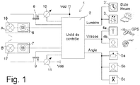
- the figure 1 shows in a simplified manner the various components of an active lighting device 1 portable or placed on a bicycle with at least two wheels.
- the lighting device 1 mainly comprises two optics referenced A and B.
- the first optic A comprises at least a first light source 16, while the second optic B comprises at least a second light source 17.
- the first light source 16 is provided for long-distance illumination and preferably at variable intensity.
- the second light source 17 is provided for illumination at a short distance and preferably at variable intensity.
- Each light source 16, 17 is a light-emitting diode or a group of light-emitting diodes selectable by a control unit 2 or all activatable at the same time.
- each optic A and B further comprises, in addition to the light sources 16, 17, an arrangement of lenses and mirrors not shown for the supply of a beam of light, as well as a drive means 6, 7 composed of '' one or two electric motors, or even two pistons or two cylinders.
- a first drive means 6 forming part of the first optics A
- a second drive means 7 forming part of the second optics B.
- each drive means 6, 7 is controlled by a unit control 2 connected to a DC power source Vdd.
- This electrical power source is preferably a DC voltage source, which comes from a rechargeable or primary battery, or which is extracted and rectified from received electromagnetic radiation.
- Each drive means 6, 7 can act on the arrangement of lenses and mirrors of optics A or B, or directly on each light source 16, 17 to orient the light beam generated by each activated light source. So as to be able to direct, for example directly the light sources 16, 17 of the optics A, B, each drive means 6, 7 can comprise two motors. So the light sources 16, 17 can be driven in rotation by each drive means 6, 7 controlled by the control unit 2 around two axes of rotation X, Y perpendicular to one another. The light beam generated in each optic A, B is oriented or directed in a direction Z perpendicular to the axes X, Y.
- the lighting device 1 also comprises one or more sensors 3, 4a, 4b, 5a, 5b, 5c connected to the control unit 2 to enable the activation of each light source 16, 17 according to a measured parameter.
- the control unit 2 supplied by the DC voltage source Vdd, is arranged, as soon as the vehicle is used, to control the lighting of the light source or sources 16, 17 of the first and second optics A , B automatically.
- the control unit 2 may also comprise a low frequency oscillator, which may be a clock or quartz crystal oscillator or MEMS, and at least one volatile or non-volatile memory.
- the volatile or non-volatile memory not shown makes it possible to store measurements made by the sensor (s) and at least one calculation algorithm for managing and calculating the measurements made by the sensors 3, 4a, 4b, 5a, 5b, 5c.
- the control unit 2 can be a calculation unit, such as a processor or microcontroller in order to be able to process all the signals received from the measurement sensor (s).
- the lighting device 1 mainly comprises a light intensity sensor or light sensor 3, which can be composed of a solar cell or an array of solar cells. From a brightness threshold detected by the light intensity sensor 3, the control unit 2 controls the activation of at least the second light source 17 of the second optic B for short-distance illumination.
- the light intensity threshold can depend directly on the ambient light in which the vehicle in use is located.
- the light intensity of the second activated light source 17 is variable and inversely proportional to the change in intensity of the ambient light.
- the lighting device 1 comprises at least one speed sensor 4a, 4b connected to the control unit 2.
- the speed sensor 4a, 4b determines the speed of the bicycle and on exceeding a determined speed threshold controls the activation of the first light source 16 of the first lens A.
- the first light source 16 generates light, if the the intensity of ambient light detected by the light sensor 3 is less than a determined light threshold.
- the second light source 17 of the second optic B is activated independently of the calculated bicycle speed, that is to say from the moment when the ambient light intensity detected by the light sensor 3 is less than the threshold of determined light.
- the speed sensor can be a GPS receiver or equivalent 4a or preferably a magnetic sensor 4b for picking up the passage of at least one permanent magnet placed on a spoke or the rim of a bicycle wheel.
- the lighting device 1 can further comprise or receive a calendar 3 ′ of the dates and times (ephemeris) of each month in the year of a place of use of the device, from which the ambient brightness is deemed insufficient.
- the control unit 2 can store this calendar 3 'of the determined place of use of the device to control the activation of the light sources 16, 17 of the optics A, B, if for example the determined speed threshold is also exceeded.
- This determined speed threshold can be set at 15 km / h or 25 km / h, but can be set to another value and stored.
- a first variator 10 is provided, connected to the supply voltage source Vdd, which is connected to a first switch. 8, which is itself connected to the first light source 16.
- the first switch 8 is controlled by the control unit 2 to activate the first light source 16, if the ambient light intensity is insufficient.
- a second dimmer 11, which is connected to the supply voltage source Vdd, is provided and connected to a second switch 9, which is itself connected to the second light source 17 of the second optic B. This second switch 9 is controlled by the control unit 2 to activate the second light source 17, if the ambient light intensity is insufficient.
- the first and second switches 8, 9 are preferably MOS transistors, such as PMOS transistors as shown, but NMOS transistors can also be envisaged.
- the source of the first PMOS transistor 8 is connected to the first variator 10, while the source of the second PMOS transistor 9 is connected to the second variator 11.
- the gate of the first PMOS transistor 8 is connected to the control unit 2 to make it conductive during the activation of the first light source 16, or non-conductive so as not to activate the first light source 16.
- the gate of the second PMOS transistor 9 is connected to the control unit 2 to make it conductive during the activation of the second light source 17 or non-conductive so as not to activate the second light source 17.
- each dimmer 10, 11 can be a current source, the current of which intended to pass through each light source is variable and increases when the ambient light intensity decreases below the determined light threshold.
- the variation of the current of each drive is directly controlled by control unit 2.
- the lighting device 1 comprises at least one orientation or tilt detector 5a, 5b, 5c connected to the control unit 2.
- the orientation or inclination detector 5a, 5b, 5c determines for example a curve made by the bicycle in use on a path or a road.
- the orientation or tilt detector 5a, 5b, 5c provides a orientation signal to the control unit 2, which controls the first and second drive means 6, 7.
- These first and second drive means 6, 7 make it possible to orient the beam or beams of light generated by the or the light sources 16, 17 of the first optic A and / or of the second optic B depending on a curve made by the bicycle in use on a path or a road.
- the orientation of the light source beams 16, 17 is such that, when turning to the right, the light beams are oriented to the right, and vice versa when turning to the left.
- the orientation detector can be composed of a potentiometer 5a and / or a magnetometer 5b and / or an inclinometer 5c and / or an accelerometer 5c and / or a gyrometer 5c as will be further explained below with reference to Figures 5a to 5c .
- the figure 2 shows the first alternative embodiment of the active lighting device for activating the light sources 16, 17 of the two optics A and B as a function of the speed of the bicycle on a road or path according to the invention.
- the light sensor 3 which supplies a signal to a first regulator 21 and to a second regulator 22 of the control unit in a light intensity loop.
- the speed sensor 4 which supplies a speed signal to a speed threshold comparator 23 and to a third regulator 24 of the control unit.
- Comparator 23 provides a comparison signal to a fourth regulator 25 of the control unit. The state of the comparison signal is either in a first state to control the activation of the first light source 16 of optics A, or in a second state to control the non-activation of the first light source 16 of l optic A.
- a first adder 26 is provided for adding the output signal of the first regulator 21 and the output signal of the fourth regulator 25, and a second adder 27 is provided for adding the output signal of the second regulator 22 and the signal output of the third regulator 24.
- the output signal of the first adder 26 controls a first dimmer 28 to vary the light intensity of the first light source 16 of the first optics A if activated.
- the output signal of the second adder 27 controls a second dimmer 29 to vary the light intensity of the second light source 17 of the second optic B still activated, if the intensity of the ambient light is below a threshold of determined light.
- the light intensity of the first light source 16 is therefore determined as the sum of the first regulator 21 inversely proportional to the ambient light, and of the fourth regulator 25 proportional to the speed of movement of the bicycle.
- the first light source 16 is only activated when a speed threshold determined by the user is exceeded, for example 25 km / h with hysteresis.
- the light intensity of the second light source 17 is therefore determined as the sum of the second regulator 22 inversely proportional to the ambient light, and of the third regulator 24 proportional to the speed of movement of the bicycle.
- the second light source 27 is always activated regardless of the speed measured, if the ambient light intensity is below a determined light threshold.
- a manual switch can also be provided so as to deactivate the lighting device with all the light sources.
- Said light sources can also be deactivated after a period of non-use of the bicycle, i.e. after a determined time without movement, for example after 5 minutes.
- each dimmer can be connected to each light source 16, 17 by a respective switch controlled by the control unit.
- the figure 3 shows a second alternative embodiment of the active lighting device for orienting the light sources 16, 17 of the optics A and B when taking a turn on a road or path according to the invention.
- a control of the ambient light by a light sensor to vary the light intensity of the light sources 16, 17, which are activated, inversely proportional to the intensity of the ambient light.
- At least one orientation or inclination detector 5 is provided, which supplies a signal to a first regulator 31 and to a second regulator 32.
- the first regulator 31 provides an output signal to a first voltage variator 33
- the second regulator 32 provides an output signal to a second voltage variator 34.
- the first voltage variator 33 controls a first actuator 35, which is at least one electric motor.
- This first actuator 35 receives control signals from the first dimmer 33, such as pulse width modulation (PWM) signals for moving or orienting for example the first light source 16 of the first optic A.
- the second dimmer voltage 34 controls a second actuator 36, which is at least one electric motor.
- This second actuator 36 receives control signals from the second variator 34, such as pulse width modulation (PWM) signals for moving or orienting for example the second light source 17 of the second optic B.
- PWM pulse width modulation
- the figure 4 schematically represents a bicycle 100 on a road 50 or a path with the activated light sources of the two optics A and B of the active lighting device 1. Both light sources are activated, if the bicycle speed is above a determined speed threshold and if the ambient light intensity is insufficient, otherwise only the second light source of optics B is activated.
- the light intensity I LUM (v, I AMB ) of the first light source of optics A depends on the speed v of the bicycle 100, and on the ambient light intensity I AMB .
- the light intensity I LUM (I AMB ) of the second light source of optics B depends only on the ambient light intensity I AMB .
- the first drive means of optics A orients said light source to illuminate even further up to a vertical azimuth, which tends towards 0.
- the light intensity of each light source can vary in proportion to the 'inverse of the ambient light intensity, or even in stages.
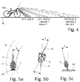
- the Figures 5a, 5b, 5c schematically show a bicycle 100 on a road 50 or a path taking a turn to orient the light sources of the optics A and B of the active lighting device 1.
- Each optic A, B can be mounted for example on a handlebar of the bicycle 100.
- the orientation or inclination detectors are for example a magnetometer 5b or an inclinometer 5c or an accelerometer 5c or a gyrometer 5c or a potentiometer 5a or a combination of these detectors as previously mentioned.
- the orientation or inclination detector can be mounted on a support, such as a helmet of the user E of the bicycle 100 and to provide an orientation signal by wireless two-way communication to the control unit arranged on the handlebars of bike 100. This allows you to control the orientation of the light source or sources by a movement of the head of the user E of the bicycle 100.
- the two light sources of the optics A and B of the lighting device 1 are activated, and must be oriented by the drive means on command of the control unit at an angle ⁇ as a function of the turn made on the road 50.
- the control unit takes account of a rotation angle ⁇ of the front wheel D of the bicycle and also of the angular movement ⁇ of the head of the user E of the bicycle relative to the direction of the rear wheel F.
Landscapes
- Engineering & Computer Science (AREA)
- Mechanical Engineering (AREA)
- Lighting Device Outwards From Vehicle And Optical Signal (AREA)
- Circuit Arrangement For Electric Light Sources In General (AREA)
Abstract
Le dispositif (1) d'éclairage actif d'un vélo comprend une première optique (A) avec une première source de lumière (16) pour une illumination à grande distance, qui est contrôlée par une unité de contrôle (2), et une seconde optique (B) avec une seconde source de lumière (17) pour une illumination à courte distance, qui est contrôlée par l'unité de contrôle. Il comprend un capteur de lumière (3) pour déterminer l'intensité lumineuse d'un endroit où se situe le vélo et permettre à l'unité de contrôle d'adapter l'intensité lumineuse des sources de lumière, si elles sont activées et si l'intensité de lumière ambiante est en dessous d'un seuil de lumière déterminé. De plus, il est prévu un capteur de vitesse (4a, 4b) pour déterminer la vitesse du vélo en utilisation sur un chemin, pour que l'unité de contrôle commande l'activation de la première source de lumière à partir d'au moins un seuil de vitesse déterminé. Il est aussi prévu un détecteur d'orientation (5a, 5b, 5c) pour orienter les sources de lumière dépendant d'une courbe effectuée par le vélo en utilisation.The active lighting device (1) of a bicycle comprises a first optic (A) with a first light source (16) for long-distance illumination, which is controlled by a control unit (2), and a second optic (B) with a second light source (17) for short distance illumination, which is controlled by the control unit. It includes a light sensor (3) to determine the light intensity of a place where the bike is located and allow the control unit to adjust the light intensity of the light sources, if they are activated and if the ambient light intensity is below a determined light threshold. In addition, a speed sensor (4a, 4b) is provided for determining the speed of the bicycle in use on a path, so that the control unit controls the activation of the first light source from at least a determined speed threshold. An orientation detector (5a, 5b, 5c) is also provided to orient the light sources depending on a curve made by the bicycle in use.
Description
L'invention concerne un dispositif d'éclairage actif portable ou placé sur un véhicule à au moins une roue, tel qu'un vélo. De préférence, chaque dispositif d'éclairage dispose d'une première optique à au moins une première source de lumière, et d'une seconde optique à au moins une seconde source de lumière, qui sont placés en partie sur le véhicule.The invention relates to an active lighting device portable or placed on a vehicle with at least one wheel, such as a bicycle. Preferably, each lighting device has a first optic with at least a first light source, and a second optic with at least a second light source, which are placed partly on the vehicle.
Pour éclairer de manière adéquate un chemin ou une route empruntée par un véhicule, il est connu d'utiliser un dispositif d'éclairage ayant un réglage adapté de l'intensité de la lumière générée de phares ou d'autres sources de lumière. Un tel dispositif d'éclairage peut aussi être adapté pour orienter le faisceau de lumière en fonction des virages à effectuer dans l'obscurité ou pour éviter d'éblouir un conducteur d'un véhicule à croiser sur la route.To adequately illuminate a path or a road taken by a vehicle, it is known to use a lighting device having a suitable adjustment of the intensity of the light generated from headlights or other light sources. Such a lighting device can also be adapted to orient the light beam according to the turns to be made in the dark or to avoid dazzling a driver of a vehicle to be encountered on the road.
La demande de brevet
La demande de brevet
Le brevet
Il est également connu par le brevet
L'invention a donc pour but de pallier les inconvénients cités ci-dessus pour réaliser un dispositif d'éclairage actif portable ou placé sur un vélo à au moins deux roues facile d'utilisation et sans complication pour permettre un bon éclairage tenant compte de la vitesse ou de l'inclinaison du véhicule.The invention therefore aims to overcome the drawbacks mentioned above to achieve an active lighting device portable or placed on a bicycle with at least two wheels easy to use and uncomplicated to allow good lighting taking into account the vehicle speed or tilt.
A cet effet, l'invention concerne un dispositif d'éclairage actif portable ou placé sur un vélo à au moins deux roues, qui comprend les caractéristiques des revendications indépendantes 1 ou 2.To this end, the invention relates to an active lighting device portable or placed on a bicycle with at least two wheels, which comprises the features of
Des formes d'exécution particulières du dispositif d'éclairage sont définies dans les revendications dépendantes 3 à 14.Particular embodiments of the lighting device are defined in
Un avantage du dispositif d'éclairage selon l'invention réside dans le fait qu'un capteur de lumière du dispositif détecte l'intensité de la lumière ambiante de manière à activer la ou les sources de lumière des optiques A et B, si l'intensité de lumière ambiante est en dessous d'un seuil de lumière déterminé. L'activation des sources de lumière peut se faire de manière automatique sur commande d'une unité de contrôle alimentée par une source de tension d'alimentation, telle qu'une batterie.An advantage of the lighting device according to the invention lies in the fact that a light sensor of the device detects the intensity of the ambient light so as to activate the light source or sources of the optics A and B, if the ambient light intensity is below a determined light threshold. The activation of the light sources can be done automatically on command of a control unit supplied by a supply voltage source, such as a battery.
Avantageusement, l'intensité de lumière des sources de lumière activées est gérée par l'unité de contrôle inversement proportionnelle à l'intensité de la lumière ambiante.Advantageously, the light intensity of the activated light sources is managed by the control unit inversely proportional to the intensity of the ambient light.
Avantageusement, un capteur de vitesse est prévu dans le dispositif d'éclairage pour activer la source de lumière de l'optique A uniquement si une vitesse du vélo en utilisation dépasse un seuil de vitesse déterminé. La source de lumière de l'optique B peut être activée dès que l'intensité de lumière ambiante est en dessous du seuil de lumière déterminé, et indépendamment de la vitesse du vélo.Advantageously, a speed sensor is provided in the lighting device to activate the light source of the optics A only if a speed of the bicycle in use exceeds a determined speed threshold. The light source of optics B can be activated as soon as the ambient light intensity is below the determined light threshold, and independently of the speed of the bicycle.
Avantageusement, au moins un détecteur d'orientation ou d'inclinaison peut aussi être prévu dans le dispositif d'éclairage pour orienter les sources de lumière en fonction d'un virage effectué par le vélo.Advantageously, at least one orientation or tilt detector can also be provided in the lighting device for orienting the light sources as a function of a turn made by the bicycle.
Les buts, avantages et caractéristiques d'un dispositif d'éclairage actif portable ou placé sur un vélo à au moins deux roues, apparaîtront mieux dans la description suivante sur la base d'au moins une forme d'exécution non limitative illustrée par les dessins sur lesquels:
- la
figure 1 représente un schéma bloc simplifié des composants du dispositif d'éclairage actif selon l'invention, - la
figure 2 représente un schéma bloc d'une forme d'exécution du dispositif d'éclairage actif pour l'activation des sources de lumière des deux optiques A et B en fonction de la vitesse du véhicule sur une route ou un chemin selon l'invention, - la
figure 3 représente un schéma bloc d'une autre forme d'exécution du dispositif d'éclairage actif pour l'orientation des sources de lumière des optiques A et B lors de la prise d'un virage sur une route ou un chemin selon l'invention, - la
figure 4 représente schématiquement un véhicule sur une route ou en chemin avec les sources de lumière activées des deux optiques A et B du dispositif d'éclairage actif en tenant compte de l'intensité de lumière et de la vitesse mesurée pour orienter le faisceau de lumière de l'optique A selon l'invention, et - les
figures 5a, 5b et 5c montrent schématiquement un vélo sur une route ou un chemin prenant un virage pour orienter les sources de lumière des optiques A et B du dispositif d'éclairage actif selon l'invention.
- the
figure 1 represents a simplified block diagram of the components of the active lighting device according to the invention, - the
figure 2 represents a block diagram of an embodiment of the active lighting device for activating the light sources of the two optics A and B as a function of the speed of the vehicle on a road or path according to the invention, - the
figure 3 represents a block diagram of another embodiment of the active lighting device for the orientation of the light sources of optics A and B when taking a turn on a road or path according to the invention, - the
figure 4 schematically represents a vehicle on a road or on the way with the activated light sources of the two optics A and B of the active lighting device taking into account the light intensity and the measured speed to orient the light beam of the optics A according to the invention, and - the
Figures 5a, 5b and 5c schematically show a bicycle on a road or path taking a turn to orient the light sources of the optics A and B of the active lighting device according to the invention.
Dans la description suivante, il est fait référence à un dispositif d'éclairage actif portable ou placé sur un vélo à au moins deux roues. Tous les composants électroniques, qui sont bien connus d'un homme du métier dans ce domaine technique, ne sont décrits que de manière simplifiée.In the following description, reference is made to an active lighting device that is portable or placed on a bicycle with at least two wheels. All the electronic components, which are well known to a person skilled in the art in this technical field, are described only in a simplified manner.
La
Chaque source de lumière 16, 17 est une diode électroluminescente ou un groupement de diodes électroluminescentes sélectionnables par une unité de contrôle 2 ou toutes activables en même temps.Each
Généralement, chaque optique A et B comprend encore en plus des sources de lumière 16, 17, un agencement de lentilles et miroirs non représenté pour la fourniture d'un faisceau de lumière, ainsi qu'un moyen d'entraînement 6, 7 composé d'un ou deux moteurs électriques, voire de deux pistons ou deux vérins. Dans le cas de figure représenté à la
Chaque moyen d'entraînement 6, 7 peut agir sur l'agencement de lentilles et miroirs de l'optique A ou B, ou directement sur chaque source de lumière 16, 17 pour orienter le faisceau de lumière généré par chaque source de lumière activée. De manière à pouvoir orienter par exemple directement les sources de lumière 16, 17 des optiques A, B, chaque moyen d'entraînement 6, 7 peut comprendre deux moteurs. Ainsi les sources de lumière 16, 17 peuvent être entraînées en rotation par chaque moyen d'entraînement 6, 7 contrôlé par l'unité de contrôle 2 autour de deux axes de rotation X, Y perpendiculaires l'un par rapport à l'autre. Le faisceau de lumière généré dans chaque optique A, B est orienté ou dirigé selon une direction Z perpendiculaire aux axes X, Y.Each drive means 6, 7 can act on the arrangement of lenses and mirrors of optics A or B, or directly on each
Le dispositif 1 d'éclairage comprend encore un ou plusieurs capteurs 3, 4a, 4b, 5a, 5b, 5c reliés à l'unité de contrôle 2 pour permettre l'activation de chaque source de lumière 16, 17 selon un paramètre mesuré. De préférence, l'unité de contrôle 2, alimenté par la source de tension continue Vdd, est agencée, dès l'utilisation du véhicule, pour contrôler l'éclairage de la ou des sources de lumière 16, 17 des première et seconde optiques A, B de manière automatique.The
L'unité de contrôle 2 peut comprendre encore un oscillateur à basse fréquence, qui peut être un oscillateur à quartz horloger ou MEMS, et au moins une mémoire volatile ou non volatile. La mémoire volatile ou non volatile non représentée permet de mémoriser des mesures effectuées par le ou les capteurs et au moins un algorithme de calcul pour la gestion et les calculs des mesures effectuées par les capteurs 3, 4a, 4b, 5a, 5b, 5c. L'unité de contrôle 2 peut être une unité de calcul, tel qu'un processeur ou microcontrôleur pour pouvoir traiter tous les signaux reçus du ou des capteurs de mesure.The
Le dispositif 1 d'éclairage comprend principalement un capteur d'intensité lumineuse ou capteur de lumière 3, qui peut être composé d'une cellule solaire ou d'un réseau de cellules solaires. A partir d'un seuil de luminosité détecté par le capteur d'intensité lumineuse 3, l'unité de contrôle 2 commande l'activation d'au moins la seconde source de lumière 17 de la seconde optique B pour une illumination à courte distance. Le seuil d'intensité lumineuse peut dépendre directement de la luminosité ambiante où se situe le véhicule en utilisation. De plus, l'intensité lumineuse de la seconde source de lumière 17 activée est variable et inversement proportionnelle au changement d'intensité de la luminosité ambiante.The
Dans une première variante de forme d'exécution du dispositif 1, le dispositif 1 d'éclairage comprend au moins un capteur de vitesse 4a, 4b relié à l'unité de contrôle 2. Lors de l'utilisation du vélo, le capteur de vitesse 4a, 4b détermine la vitesse du vélo et à partir du dépassement d'un seuil de vitesse déterminé commande l'activation de la première source de lumière 16 de la première optique A. La première source de lumière 16 génère de la lumière, si l'intensité de lumière ambiante détectée par le capteur de lumière 3 est inférieure à un seuil de lumière déterminé. La seconde source de lumière 17 de la seconde optique B est activée indépendamment de la vitesse du vélo calculée, c'est-à-dire dès le moment où l'intensité de lumière ambiante détectée par le capteur de lumière 3 est inférieure au seuil de lumière déterminé.In a first variant embodiment of the
Le capteur de vitesse peut être un récepteur GPS ou équivalent 4a ou de préférence un capteur magnétique 4b pour capter le passage d'au moins un aimant permanent disposé sur un rayon ou la jante d'une roue du vélo. Chaque impulsion magnétique de passage de l'aimant permanent à proximité du capteur magnétique 4b, et selon une cadence dans le temps générée par l'oscillateur basse fréquence, permet à l'unité de contrôle 2 de calculer la vitesse et le moment du dépassement du seuil de vitesse déterminé.The speed sensor can be a GPS receiver or equivalent 4a or preferably a
Le dispositif 1 d'éclairage peut comprendre encore ou recevoir un calendrier 3' des dates et heures (éphémérides) de chaque mois dans l'année d'un lieu d'utilisation du dispositif, à partir de laquelle la luminosité ambiante est jugée insuffisante. L'unité de contrôle 2 peut mémoriser ce calendrier 3' du lieu déterminé d'utilisation du dispositif pour contrôler l'activation des sources de lumière 16, 17 des optiques A, B, si par exemple le seuil de vitesse déterminé est aussi dépassé. Ce seuil de vitesse déterminé peut être fixé à 15 km/h ou 25 km/h, mais peut être défini à une autre valeur et mémorisé.The
Pour ce faire, il est prévu un premier variateur 10 connecté à la source de tension d'alimentation Vdd, qui est relié à un premier interrupteur 8, qui est lui-même relié à la première source de lumière 16. Le premier interrupteur 8 est commandé par l'unité de contrôle 2 pour activer la première source de lumière 16, si l'intensité de lumière ambiante est insuffisante. Un second variateur 11, qui est connecté à la source de tension d'alimentation Vdd, est prévu et relié à un second interrupteur 9, qui est lui-même relié à la seconde source de lumière 17 de la seconde optique B. Ce second interrupteur 9 est commandé par l'unité de contrôle 2 pour activer la seconde source de lumière 17, si l'intensité de lumière ambiante est insuffisante.To do this, a
Les premier et second interrupteurs 8, 9 sont de préférence des transistors MOS, tels que des transistors PMOS comme représentés, mais des transistors NMOS peuvent aussi être envisagés. La source du premier transistor PMOS 8 est reliée au premier variateur 10, alors que la source du second transistor PMOS 9 est reliée au second variateur 11. La grille du premier transistor PMOS 8 est reliée à l'unité de contrôle 2 pour le rendre conducteur lors de l'activation de la première source de lumière 16, ou non conducteur pour ne pas activer la première source de lumière 16. La grille du second transistor PMOS 9 est reliée à l'unité de contrôle 2 pour le rendre conducteur lors de l'activation de la seconde source de lumière 17 ou non conducteur pour ne pas activer la seconde source de lumière 17.The first and
Il est à noter que chaque variateur 10, 11 peut être une source de courant, dont le courant prévu pour passer dans chaque source de lumière est variable et augmente quand l'intensité de lumière ambiante diminue en dessous du seuil de lumière déterminé. La variation du courant de chaque variateur est contrôlée directement par l'unité de contrôle 2.It should be noted that each dimmer 10, 11 can be a current source, the current of which intended to pass through each light source is variable and increases when the ambient light intensity decreases below the determined light threshold. The variation of the current of each drive is directly controlled by
Dans une seconde variante de forme d'exécution du dispositif 1, le dispositif 1 d'éclairage comprend au moins un détecteur d'orientation ou d'inclinaison 5a, 5b, 5c relié à l'unité de contrôle 2. Lors de l'utilisation du vélo, le détecteur d'orientation ou d'inclinaison 5a, 5b, 5c détermine par exemple une courbe effectuée par le vélo en utilisation sur un chemin ou une route. Le détecteur d'orientation ou d'inclinaison 5a, 5b, 5c fournit un signal d'orientation à l'unité de contrôle 2, qui commande les premier et second moyens d'entraînement 6, 7. Ces premier et second moyens d'entraînement 6, 7 permettent d'orienter le ou les faisceaux de lumière générés par la ou les sources de lumière 16, 17 de la première optique A et/ou de la seconde optique B dépendant d'une courbe effectuée par le vélo en utilisation sur un chemin ou une route. L'orientation des faisceaux des sources de lumière 16, 17 est telle que, lors d'un virage à droite, les faisceaux de lumière sont orientés vers la droite, et inversement lors d'un virage à gauche.In a second variant embodiment of the
On peut imaginer dans cette seconde variante d'avoir les deux sources de lumière 16, 17 activées dès que l'intensité de la lumière ambiante est en dessous d'un seuil de lumière déterminé. Cependant il peut aussi être prévu d'activer uniquement la seconde source de lumière 17, si la vitesse détectée par le capteur de vitesse 4a, 4b ne dépasse pas le seuil de vitesse déterminé. De plus, il peut être prévu que les premier et second moyens d'entraînement 6, 7 orientent directement les première et seconde sources de lumière 16, 17 des optiques A et B.One can imagine in this second variant of having the two
Le détecteur d'orientation peut être composé d'un potentiomètre 5a et/ou d'un magnétomètre 5b et/ou d'un inclinomètre 5c et/ou d'un accéléromètre 5c et/ou d'un gyromètre 5c comme il sera encore expliqué ci-après en référence aux
La
Pour simplifier, il est prévu le capteur de lumière 3, qui fournit un signal à un premier régulateur 21 et à un second régulateur 22 de l'unité de contrôle dans une boucle d'intensité lumineuse. Il est encore prévu le capteur de vitesse 4, qui fournit un signal de vitesse à un comparateur de seuil de vitesse 23 et à un troisième régulateur 24 de l'unité de contrôle. Le comparateur 23 fournit un signal de comparaison à un quatrième régulateur 25 de l'unité de contrôle. L'état du signal de comparaison est soit dans un premier état pour commander l'activation de la première source de lumière 16 de l'optique A, soit dans un second état pour commander la non activation de la première source de lumière 16 de l'optique A. Un premier additionneur 26 est prévu pour additionner le signal de sortie du premier régulateur 21 et le signal de sortie du quatrième régulateur 25, et un second additionneur 27 est prévu pour additionner le signal de sortie du second régulateur 22 et le signal de sortie du troisième régulateur 24. Le signal de sortie du premier additionneur 26 commande un premier variateur 28 pour varier l'intensité lumineuse de la première source de lumière 16 de la première optique A si activée. Le signal de sortie du second additionneur 27 commande un second variateur 29 pour varier l'intensité lumineuse de la seconde source de lumière 17 de la seconde optique B toujours activée, si l'intensité de la lumière ambiante est en dessous d'un seuil de lumière déterminé.To simplify, the
L'intensité lumineuse de la première source de lumière 16 est donc déterminée comme la somme du premier régulateur 21 inversement proportionnel à la luminosité ambiante, et du quatrième régulateur 25 proportionnel à la vitesse de déplacement du vélo. Cependant la première source de lumière 16 n'est activée que lorsqu'un seuil de vitesse déterminé par l'utilisateur est dépassé par exemple 25 km/h avec hystérèse.The light intensity of the
L'intensité lumineuse de la seconde source de lumière 17 est donc déterminée comme la somme du second régulateur 22 inversement proportionnel à la luminosité ambiante, et du troisième régulateur 24 proportionnel à la vitesse de déplacement du vélo. Dans ce cas de figure, la seconde source de lumière 27 est toujours activée indépendamment de la vitesse mesurée, si l'intensité de lumière ambiante est en dessous d'un seuil de lumière déterminé.The light intensity of the second
Bien entendu, lorsque le vélo n'est plus en utilisation, il peut aussi être prévu un interrupteur manuel de manière à désactiver le dispositif d'éclairage avec toutes les sources de lumière. Lesdites sources de lumière peuvent être aussi désactivées après une période d'inutilisation du vélo, c'est-à-dire après un temps déterminé sans mouvement par exemple après 5 minutes.Of course, when the bicycle is no longer in use, a manual switch can also be provided so as to deactivate the lighting device with all the light sources. Said light sources can also be deactivated after a period of non-use of the bicycle, i.e. after a determined time without movement, for example after 5 minutes.
En comparaison à ce qui a été décrit en référence à la
La
Pour simplifier dans cette boucle de trajectoire, il est prévu au moins un détecteur d'orientation ou d'inclinaison 5, qui fournit un signal à un premier régulateur 31 et à un second régulateur 32. Le premier régulateur 31 fournit un signal de sortie à un premier variateur de tension 33, et le second régulateur 32 fournit un signal de sortie à un second variateur de tension 34. Le premier variateur de tension 33 contrôle un premier actuateur 35, qui est au moins un moteur électrique. Ce premier actuateur 35 reçoit des signaux de commande du premier variateur 33, tels que des signaux à modulation de largeur d'impulsion (PWM) pour déplacer ou orienter par exemple la première source de lumière 16 de la première optique A. Le second variateur de tension 34 contrôle un second actuateur 36, qui est au moins un moteur électrique. Ce second actuateur 36 reçoit des signaux de commande du second variateur 34, tels que des signaux à modulation de largeur d'impulsion (PWM) pour déplacer ou orienter par exemple la seconde source de lumière 17 de la seconde optique B.To simplify in this trajectory loop, at least one orientation or
La
Comme montré à la
Les
Le détecteur d'orientation ou d'inclinaison peut être monté sur un support, tel qu'un casque de l'utilisateur E du vélo 100 et pour fournir un signal d'orientation par une communication bidirectionnelle sans fil à l'unité de contrôle disposée sur le guidon du vélo 100. Ceci permet de contrôler l'orientation de la ou des sources de lumière par un mouvement de la tête de l'utilisateur E du vélo 100.The orientation or inclination detector can be mounted on a support, such as a helmet of the user E of the
A la
A la
A la
A partir de la description qui vient d'être faite, plusieurs variantes de réalisation d'un dispositif d'éclairage actif portable ou placé sur un vélo à au moins deux roues sont possibles sans sortir du cadre de l'invention définie par les revendications suivantes.From the description which has just been made, several alternative embodiments of a portable active lighting device or placed on a bicycle with at least two wheels are possible without departing from the scope of the invention defined by the following claims .
Claims (14)
caractérisé en ce que le dispositif comprend:
characterized in that the device comprises:
caractérisé en ce que le dispositif comprend :
characterized in that the device comprises:
Applications Claiming Priority (1)
| Application Number | Priority Date | Filing Date | Title |
|---|---|---|---|
| EP18191097.7A EP3616989A1 (en) | 2018-08-28 | 2018-08-28 | Portable or vehicle-mounted active lighting device |
Publications (1)
| Publication Number | Publication Date |
|---|---|
| EP3616991A1 true EP3616991A1 (en) | 2020-03-04 |
Family
ID=63490216
Family Applications (2)
| Application Number | Title | Priority Date | Filing Date |
|---|---|---|---|
| EP18191097.7A Withdrawn EP3616989A1 (en) | 2018-08-28 | 2018-08-28 | Portable or vehicle-mounted active lighting device |
| EP19184419.0A Pending EP3616991A1 (en) | 2018-08-28 | 2019-07-04 | Bicycle-mounted active lighting device device |
Family Applications Before (1)
| Application Number | Title | Priority Date | Filing Date |
|---|---|---|---|
| EP18191097.7A Withdrawn EP3616989A1 (en) | 2018-08-28 | 2018-08-28 | Portable or vehicle-mounted active lighting device |
Country Status (4)
| Country | Link |
|---|---|
| US (1) | US10940906B2 (en) |
| EP (2) | EP3616989A1 (en) |
| JP (1) | JP6977001B2 (en) |
| CN (1) | CN110901797B (en) |
Families Citing this family (2)
| Publication number | Priority date | Publication date | Assignee | Title |
|---|---|---|---|---|
| JP2022079035A (en) * | 2020-11-16 | 2022-05-26 | カワサキモータース株式会社 | Saddle-riding type vehicle and control method of light of the same |
| DE102021131816B3 (en) * | 2021-12-02 | 2023-04-27 | Jochen Klieber | Additional lighting device for a two-wheeler and two-wheeler with it |
Citations (8)
| Publication number | Priority date | Publication date | Assignee | Title |
|---|---|---|---|---|
| FR2844759B1 (en) | 2002-09-20 | 2007-04-06 | Ecole Nationale D Ingenieurs D | GYROSTABLE HEADLIGHT FOR MOTORCYCLE |
| CN202593696U (en) * | 2012-05-23 | 2012-12-12 | 成贯企业有限公司 | Bicycle lamp with function of manually and automatically adjusting lighting distance |
| EP3036149A1 (en) | 2013-08-21 | 2016-06-29 | Mcaleese, William Philip | Lighting device for a bicycle |
| CN205716835U (en) * | 2016-02-18 | 2016-11-23 | 李文杰 | A kind of dynamo lighting set |
| WO2017023293A1 (en) | 2015-08-03 | 2017-02-09 | Ford Global Technologies, Llc | Intelligent bicycle lighting system for optimal road visibility |
| US20180020528A1 (en) | 2016-07-13 | 2018-01-18 | Yam Ho Yeung | Smart lighting system and method |
| JP2018062260A (en) * | 2016-10-13 | 2018-04-19 | ボッシュ株式会社 | Bicycle lighting unit and bicycle |
| WO2018112656A1 (en) * | 2016-12-22 | 2018-06-28 | 2948-4292 Quebec Inc. | Adaptive light beam unit and use of same |
Family Cites Families (21)
| Publication number | Priority date | Publication date | Assignee | Title |
|---|---|---|---|---|
| JPH02121009A (en) * | 1988-10-31 | 1990-05-08 | Suzuki Motor Co Ltd | Device to control direction of object to be controlled according to posture of driver |
| JP3014253B2 (en) * | 1993-09-17 | 2000-02-28 | 株式会社ミツバ | Bicycle headlight device |
| JPH07329851A (en) * | 1994-06-03 | 1995-12-19 | Sharp Corp | Automatic lighting and illuminating device for bicycle |
| DE4431332A1 (en) * | 1994-09-02 | 1996-05-02 | Josic Ante | Automatic lighting system for motor vehicles of all kinds and a method for controlling a lighting system |
| US6587573B1 (en) * | 2000-03-20 | 2003-07-01 | Gentex Corporation | System for controlling exterior vehicle lights |
| JP2001213227A (en) | 2000-02-04 | 2001-08-07 | Koito Mfg Co Ltd | Lighting system for vehicle |
| JP2001219881A (en) * | 2000-02-09 | 2001-08-14 | Yamaha Motor Co Ltd | Control device for saddle riding vehicle |
| ATE394298T1 (en) * | 2002-10-18 | 2008-05-15 | Shimano Kk | BICYCLE LIGHT SYSTEM |
| JP2005225426A (en) * | 2004-02-16 | 2005-08-25 | Shimano Inc | Bicycle lighting system and bicycle display device that can be fitted thereto |
| JP2007145233A (en) * | 2005-11-29 | 2007-06-14 | Denso Corp | Light irradiation system |
| JP4656429B2 (en) * | 2006-06-02 | 2011-03-23 | 株式会社デンソー | Headlight control system |
| US20100123402A1 (en) * | 2008-11-19 | 2010-05-20 | Yi-Lun Chen | Bicycle control device |
| JP2011201382A (en) * | 2010-03-25 | 2011-10-13 | Mitsuba Corp | Headlight for bicycle |
| US8983135B2 (en) | 2012-06-01 | 2015-03-17 | Gentex Corporation | System and method for controlling vehicle equipment responsive to a multi-stage village detection |
| JP2014000876A (en) * | 2012-06-18 | 2014-01-09 | Yamaha Motor Co Ltd | Sub-headlight unit and sub-headlight system for vehicles to turn in lean positions, and vehicle for turning in lean positions |
| WO2014057681A1 (en) * | 2012-10-11 | 2014-04-17 | 三菱電機株式会社 | Vehicle headlight device |
| US20160001836A1 (en) * | 2014-07-02 | 2016-01-07 | Wen-Sung Lee | Intellectual bicycle lamp |
| JP6599613B2 (en) * | 2014-12-25 | 2019-10-30 | 株式会社小糸製作所 | Light distribution variable vehicle lamp |
| GB201511303D0 (en) * | 2015-06-26 | 2015-08-12 | Gherezghiher Amanuel And Gerez Bikes Ltd | Gerez bike |
| US9926028B2 (en) * | 2015-12-30 | 2018-03-27 | Tina Su | Assembly of a light and a watch of a bicycle capable for adjusting angle |
| JP6894195B2 (en) * | 2016-06-14 | 2021-06-30 | 株式会社シマノ | Bicycle display device |
-
2018
- 2018-08-28 EP EP18191097.7A patent/EP3616989A1/en not_active Withdrawn
-
2019
- 2019-07-04 EP EP19184419.0A patent/EP3616991A1/en active Pending
- 2019-08-13 JP JP2019148340A patent/JP6977001B2/en active Active
- 2019-08-20 US US16/545,208 patent/US10940906B2/en active Active
- 2019-08-23 CN CN201910781602.8A patent/CN110901797B/en active Active
Patent Citations (8)
| Publication number | Priority date | Publication date | Assignee | Title |
|---|---|---|---|---|
| FR2844759B1 (en) | 2002-09-20 | 2007-04-06 | Ecole Nationale D Ingenieurs D | GYROSTABLE HEADLIGHT FOR MOTORCYCLE |
| CN202593696U (en) * | 2012-05-23 | 2012-12-12 | 成贯企业有限公司 | Bicycle lamp with function of manually and automatically adjusting lighting distance |
| EP3036149A1 (en) | 2013-08-21 | 2016-06-29 | Mcaleese, William Philip | Lighting device for a bicycle |
| WO2017023293A1 (en) | 2015-08-03 | 2017-02-09 | Ford Global Technologies, Llc | Intelligent bicycle lighting system for optimal road visibility |
| CN205716835U (en) * | 2016-02-18 | 2016-11-23 | 李文杰 | A kind of dynamo lighting set |
| US20180020528A1 (en) | 2016-07-13 | 2018-01-18 | Yam Ho Yeung | Smart lighting system and method |
| JP2018062260A (en) * | 2016-10-13 | 2018-04-19 | ボッシュ株式会社 | Bicycle lighting unit and bicycle |
| WO2018112656A1 (en) * | 2016-12-22 | 2018-06-28 | 2948-4292 Quebec Inc. | Adaptive light beam unit and use of same |
Also Published As
| Publication number | Publication date |
|---|---|
| EP3616989A1 (en) | 2020-03-04 |
| US20200070915A1 (en) | 2020-03-05 |
| JP2020033006A (en) | 2020-03-05 |
| US10940906B2 (en) | 2021-03-09 |
| JP6977001B2 (en) | 2021-12-08 |
| CN110901797B (en) | 2022-07-05 |
| CN110901797A (en) | 2020-03-24 |
Similar Documents
| Publication | Publication Date | Title |
|---|---|---|
| EP3617049A1 (en) | Bicycle-mounted active lighting device device | |
| EP3616991A1 (en) | Bicycle-mounted active lighting device device | |
| WO2015044384A2 (en) | Driving assistance device and method | |
| WO2007060336A2 (en) | Motorised transport vehicle for pedestrians | |
| EP3367754B1 (en) | Method and control module for pulsed light flow light sources of a motor vehicle | |
| FR2867119A1 (en) | DEVICE FOR AUTOMATICALLY ADJUSTING THE BEAM AXIS OF A VEHICLE HEADLIGHT | |
| FR2840541A1 (en) | MOTORIZED REMOTE CONTROLLED MOBILE TOY | |
| EP1821032A1 (en) | Projector, in particular with an LED, for an automobile | |
| EP1388460A2 (en) | Control device for automatic adjustment of the position of an automobile headlamp | |
| WO2016128114A1 (en) | Method for detecting an inclination of a wheel relative to the horizontal | |
| CH715274A2 (en) | Active lighting device portable or placed on a bicycle. | |
| CH715275A2 (en) | Active lighting device portable or placed on a bicycle. | |
| EP3638539B1 (en) | System for compensating the tilt angle variations of a device of a transport means relative to the earth's gravitational axis | |
| FR3048673A1 (en) | ELECTRIC ASSISTANCE CYCLE, SYSTEM COMPRISING SUCH A CYCLE AND USE OF SUCH A CYCLE | |
| EP3877316B1 (en) | Method and device for helping to position forks of a handling machine | |
| FR2895359A1 (en) | Autonomous mobile foot passenger device, for transport of pedestrians on sidewalks, has a platform on which the passenger stands and is able to control his movement solely using foot activated controls | |
| FR2988052A1 (en) | Method for adapting e.g. brightness of illuminating or signaling light source of car, involves determining brightness value of light source, and adjusting brightness value in order to reach value of determined characteristic brightness | |
| FR3084050A1 (en) | ADAPTIVE LIGHTING DEVICE FOR CYCLES | |
| EP0659610B1 (en) | Autoadaptive adjusting device for rear view mirror with electrical control | |
| WO2020008027A1 (en) | Control system for a hybrid bicycle, and hybrid bicycle equipped with such a control system | |
| FR3042449A1 (en) | DEVICE AND METHOD FOR MANAGING THE ELECTRIC MOTORIZATION MEANS OF AN ELECTRICALLY ASSISTED VEHICLE | |
| EP3575802B1 (en) | Method and system for measuring speed and/or a distance travelled by a bicycle | |
| WO2022129617A1 (en) | Light-emitting device for a motor vehicle | |
| EP2589511A1 (en) | Luminous protective helmet | |
| FR2858277A1 (en) | INTEGRABLE TURN DETECTION MEANS IN A DEVICE FOR CONTROLLING A TURN-FUNCTION LIGHTING SYSTEM |
Legal Events
| Date | Code | Title | Description |
|---|---|---|---|
| PUAI | Public reference made under article 153(3) epc to a published international application that has entered the european phase |
Free format text: ORIGINAL CODE: 0009012 |
|
| STAA | Information on the status of an ep patent application or granted ep patent |
Free format text: STATUS: THE APPLICATION HAS BEEN PUBLISHED |
|
| AK | Designated contracting states |
Kind code of ref document: A1 Designated state(s): AL AT BE BG CH CY CZ DE DK EE ES FI FR GB GR HR HU IE IS IT LI LT LU LV MC MK MT NL NO PL PT RO RS SE SI SK SM TR |
|
| AX | Request for extension of the european patent |
Extension state: BA ME |
|
| STAA | Information on the status of an ep patent application or granted ep patent |
Free format text: STATUS: REQUEST FOR EXAMINATION WAS MADE |
|
| 17P | Request for examination filed |
Effective date: 20200904 |
|
| RBV | Designated contracting states (corrected) |
Designated state(s): AL AT BE BG CH CY CZ DE DK EE ES FI FR GB GR HR HU IE IS IT LI LT LU LV MC MK MT NL NO PL PT RO RS SE SI SK SM TR |
|
| STAA | Information on the status of an ep patent application or granted ep patent |
Free format text: STATUS: EXAMINATION IS IN PROGRESS |
|
| 17Q | First examination report despatched |
Effective date: 20211104 |
|
| P01 | Opt-out of the competence of the unified patent court (upc) registered |
Effective date: 20230615 |