EP3403546A1 - Brewing module and machine for making beverages - Google Patents
Brewing module and machine for making beverages Download PDFInfo
- Publication number
- EP3403546A1 EP3403546A1 EP17172058.4A EP17172058A EP3403546A1 EP 3403546 A1 EP3403546 A1 EP 3403546A1 EP 17172058 A EP17172058 A EP 17172058A EP 3403546 A1 EP3403546 A1 EP 3403546A1
- Authority
- EP
- European Patent Office
- Prior art keywords
- brewing module
- brewing
- movement
- housing
- damping
- Prior art date
- Legal status (The legal status is an assumption and is not a legal conclusion. Google has not performed a legal analysis and makes no representation as to the accuracy of the status listed.)
- Withdrawn
Links
Images


Classifications
-
- A—HUMAN NECESSITIES
- A47—FURNITURE; DOMESTIC ARTICLES OR APPLIANCES; COFFEE MILLS; SPICE MILLS; SUCTION CLEANERS IN GENERAL
- A47J—KITCHEN EQUIPMENT; COFFEE MILLS; SPICE MILLS; APPARATUS FOR MAKING BEVERAGES
- A47J31/00—Apparatus for making beverages
- A47J31/24—Coffee-making apparatus in which hot water is passed through the filter under pressure, i.e. in which the coffee grounds are extracted under pressure
- A47J31/34—Coffee-making apparatus in which hot water is passed through the filter under pressure, i.e. in which the coffee grounds are extracted under pressure with hot water under liquid pressure
- A47J31/36—Coffee-making apparatus in which hot water is passed through the filter under pressure, i.e. in which the coffee grounds are extracted under pressure with hot water under liquid pressure with mechanical pressure-producing means
- A47J31/3604—Coffee-making apparatus in which hot water is passed through the filter under pressure, i.e. in which the coffee grounds are extracted under pressure with hot water under liquid pressure with mechanical pressure-producing means with a mechanism arranged to move the brewing chamber between loading, infusing and ejecting stations
- A47J31/3623—Cartridges being employed
- A47J31/3633—Means to perform transfer from a loading position to an infusing position
-
- A—HUMAN NECESSITIES
- A47—FURNITURE; DOMESTIC ARTICLES OR APPLIANCES; COFFEE MILLS; SPICE MILLS; SUCTION CLEANERS IN GENERAL
- A47J—KITCHEN EQUIPMENT; COFFEE MILLS; SPICE MILLS; APPARATUS FOR MAKING BEVERAGES
- A47J31/00—Apparatus for making beverages
- A47J31/24—Coffee-making apparatus in which hot water is passed through the filter under pressure, i.e. in which the coffee grounds are extracted under pressure
- A47J31/34—Coffee-making apparatus in which hot water is passed through the filter under pressure, i.e. in which the coffee grounds are extracted under pressure with hot water under liquid pressure
- A47J31/36—Coffee-making apparatus in which hot water is passed through the filter under pressure, i.e. in which the coffee grounds are extracted under pressure with hot water under liquid pressure with mechanical pressure-producing means
- A47J31/3604—Coffee-making apparatus in which hot water is passed through the filter under pressure, i.e. in which the coffee grounds are extracted under pressure with hot water under liquid pressure with mechanical pressure-producing means with a mechanism arranged to move the brewing chamber between loading, infusing and ejecting stations
- A47J31/3647—Coffee-making apparatus in which hot water is passed through the filter under pressure, i.e. in which the coffee grounds are extracted under pressure with hot water under liquid pressure with mechanical pressure-producing means with a mechanism arranged to move the brewing chamber between loading, infusing and ejecting stations a tape being employed
- A47J31/3652—Coffee-making apparatus in which hot water is passed through the filter under pressure, i.e. in which the coffee grounds are extracted under pressure with hot water under liquid pressure with mechanical pressure-producing means with a mechanism arranged to move the brewing chamber between loading, infusing and ejecting stations a tape being employed the tape including only filtering means, i.e. not including brewing material
Definitions
- the invention relates to extraction devices for preparing beverages or the like from an extraction material contained in a portion capsule, for example ground coffee. It relates in particular to a brewing module for an extraction device, a capsule recognition module and a beverage preparation machine with such a brewing module and / or capsule recognition module.
- Extraction devices for preparing beverages or the like from an extraction material present in a portion package are known, for example, as coffee or espresso machines.
- the portion packages are designed as capsules, in which the extraction material, for example, is airtight.
- the capsule is pierced, for example on two opposite sides. On the first side then an extraction liquid - generally hot water - is introduced. On the second side, the extraction product is discharged from the capsule. This happens in a so-called brewing module.
- brewing module Such has a brewing chamber in which the capsule is received.
- Brewing modules in which the capsule is inserted and the brewing chamber is manually closed by means of an operating lever are particularly popular, the capsule being automatically removed from the brewing chamber and ejected into a capsule container when the brewing chamber is opened again after the brewing process.
- Such brewing modules with automatic capsule ejection are generally designed as horizontal brewing modules, ie the capsule is inserted from above, the closure of the brewing chamber is a horizontal relative movement of two brewing module parts, the brewing liquid flows substantially horizontally, and the capsule container is formed below the brewing chamber.
- a damping device for damping a closing or opening movement of a brewing module is for example already out of EP 2 485 629 known. This is related to a spring drive during the opening movement and serves in particular to prevent that takes place at the end of the opening movement too violent striking a stop.
- the damping device can work on inertia and friction, but also on friction alone, hydraulically, by air damping, magnetic, etc. and generally attenuates the closing and the opening movement evenly.
- the brewing module has a damping device for damping the movement of the second brewing module part.
- the damping device is designed so that it has a non-constant in function of the position and / or direction of movement damping characteristic.
- the movement of the second brewing module part from the first to the second position is also called “closing movement” and the reverse movement is called “opening movement”.
- the damping device may be designed such that it only attenuates along a partial path of the displacement path and / or only during the closing movement or only during the opening movement.
- the inventive approach allows for non-constant mechanical resistance during the closing process or during the opening process attenuation takes place deliberately there or occurs where the resistance decreases abruptly as a function of the path of the second Brühmodulteils.
- the damping device can prevent jerking, which can not only have a positive effect on the perception by the user, but also on the life of the brewing module by jerky movements are avoided.
- the damping device can be formed in that two relatively moving parts of the brewing module - for example.
- a cam and the housing or the second Brühmodulteil and the housing - each have a contact portion, which come into physical contact with each other only on a leg of the displacement distance and rub against each other.
- Such contact parts can be formed, for example, by a sliding surface on the one hand and an elastic damping element on the other hand.
- the one of the contact parts is formed by a damping element, which in the closing movement and during the opening movement in different degrees against the other Contact part is pressed - especially at the opening movement or during the closing movement not at all.
- the damping element may be formed as an elastic element, which is movably received in a receptacle of the corresponding part of the brewing module, being pressed against the other contact part during one movement (eg during the closing movement). This may, for example, be effected, for example, by the receptacle towards the direction in which the damping element is pressed during a movement, having a constriction, in which the damping element is compressed between the two parts, while during the opening movement of the other contact portion can dodge away.
- the damping element may, for example, be designed as an elastic ring (damping ring). Instead of a damping ring and another example, elastic damping element can be used, for example. An elastic lip or an elastically deformable cushion.
- the damping element is arranged and formed so that when it comes into contact with the sliding surface, it is deformed by a movement relative to the sliding surface in one direction and exerts an elastic, deformation-opposing force on the sliding surface, while at a Movement can dodge in the other direction and can slide along the sliding surface substantially force-free.
- a damping element which is clamped during movement in one of the directions of movement in a constriction, such a deformation is effected by compression of the damping element.
- the lip is not perpendicular to the Sliding surface is but at a non-right angle to, ie it projects obliquely to the sliding surface and to the side, in which they in the closing movement (when this is to be damped in a section) or during the opening movement is moved.
- the housing has a sliding surface which projects toward the second brewing module part or to another element moving during its movement, for example a cam of the transmission mechanism, and in that the moving element (brewing module part, cam, other element) a damping element, which is pressed due to an elastic force and / or due to jamming on the leg and / or in at least one direction of movement against the sliding surface - or vice versa.
- Such a sliding surface may have a varying distance to the damping element as a function of the position, so that the friction force changes as a function of the position.
- a damping element may in particular be made of an elastomer.
- the transmission mechanism for transmitting the movement of the operating element may have a cam plate rotatably mounted on the housing with a first guide surface, wherein the second Brühmodulteil is displaced by the first guide surface along a housing-fixed displacement distance from the first Brühmodulteil position to the second Brühmodulteil position by the Cam is rotated, and that the first guide surface along the first guide surface significantly (for example, by at least a factor of 2) varying transmission ratio (ratio between the second Brühmodulteil distance traveled on the one hand and the distance traveled by the cam angular movement on the other hand) defined.
- the transmission ratio varies significantly. In embodiments, it differs between the largest and the smallest value by at least a factor of 2, often by at least a factor of 4, 6, 8, 10 or more.
- the gear ratio may in particular be selected so that it is smaller at a larger closing force than where the closing force is small.
- the cam disc can also define a second guide surface, by which the second brewing module part is displaceable along the housing-fixed displacement path from the second brewing module part position into the first brewing module part position.
- a second guide surface can in particular also run in such a way that a variable transmission ratio is defined along it, for example likewise in sections, and also substantially, for example, with a factor between the largest and the smallest transmission ratio of at least 2, or at least a factor of 4, 6. 8, 10 or more.
- the first and second guide surfaces may be formed as boundaries of a guide hole in the cam (such opening may be a through hole or a recess).
- An example, pin-like guide element which is connected to the second Brühmodulteil, for example. By being molded on this or is guided by this, then engages in this guide opening.
- the second guide surface may be non-parallel to the first guide surface, i. It is not necessary that the transmission ratios at a certain position of the second Brühmodulteils during the closing and the opening movement are equal.
- the second brewing module part is for example linear-translatory, in particular horizontally movable relative to the housing, i. the displacement distance is in particular linear and horizontal.
- the first brewing module part can be mounted fixed to the housing. However, it is also possible that the first brewing module part is also movable and, for example, makes a movement opposite to the second brewing module part.
- the housing-fixed displacement section can be defined, for example, by a guide track, for example a guide groove, of the housing into which a guide element connected to the second brewing module part, for example a guide pin, engages.
- a guide element can also interact with the guide surface, wherein then a portion of the guide element engages in the guide track and another portion cooperates with the guide surface.
- a guide element may optionally be provided with two mutually decoupled bearings, one of which is in engagement with the guide track and a second with the guide surface.
- the second brewing module part may be an injector, through which the portion capsule is pierced and from which, for example, hot water is introduced as brewing liquid into the portion capsule.
- the first brewing module part may form a discharge device for discharging the extraction product from the capsule.
- it has extraction-side piercing elements for the extraction-side piercing of the capsule or other structures, which open the capsule on the extraction side.
- the first brewing module part can form the injector and the second brewing module part the discharge device.
- the operating element may in particular be an operating lever which can be brought from the first to the second position by a tilting movement from top to bottom. In the second position, for example, the operating lever closes a capsule insertion opening, which is formed by a housing of the beverage preparation machine-for example, the brewing module.
- the invention also relates to a beverage preparation machine with a brewing module of the type discussed.
- the brewing module 1 has a Brühmodulgephase. 2 In Brühmodulgephaseuse 2 two relatively movable Brühmodulmaschine be performed, namely a discharge device 3 and an injector 4.
- the housing has two housing side parts 21 here.
- the injector 4 has perforation elements for piercing a portion capsule, which is at least partially filled with an extraction material - for example, ground coffee.
- the injector 4 is set up to introduce a liquid-for example hot water-through the perforation elements or past them into the pierced capsule, wherein the water can be supplied via a water supply (not shown) which, for example, may have a flexible hose.
- the diverting device 3 has in the embodiment described here on perforation, namely extraction-side piercing tips. These may be formed, for example, as in WO 2015/039258 or in WO 2010/118544 described or have another embodiment; the use of other principles than piercing tips, for example. With lattice-like structures are possible.
- a capsule is placed between the discharge device 3 and the injector 4, and these are moved toward each other in such a way that a brewing chamber comprising the capsule is formed between them.
- the hot water is supplied through the injector under pressure of the capsule, and the extraction product flows through the Diversion device 3 via a beverage outlet 13 in an example. Below placed drinking vessel from.
- the relative movement of the second brewing module part (injector) relative to the first brewing module part (discharge device) is achieved in the exemplary embodiment described here in that the discharge device 3 is mounted fixed to the housing while the injector 4 is movable along the horizontal axis.
- the user Before the preparation of a brewing beverage, the user inserts a capsule via a capsule insertion opening arranged on the top side of the housing, which capsule is replaced by appropriate means, for example as in WO 2015/048914 is kept at the designated height until the brewing chamber is closed.
- Such insertion of the capsule in the brewing chamber can be done directly, or as, for example, in WO 2016/087190 described, indirectly, by the capsule is first held at a position above the brewing chamber, for example.
- a capsule recognition For the purpose of a capsule recognition.
- the brewing module For operation by the user for the purpose of closing the brewing chamber, the brewing module has an operating lever 6 which is fastened fixedly to a cam plate arrangement composed of two cams 30.
- the cams in turn are each pivotally mounted about a pivot 31 which is arranged in a respective bore 32 in the corresponding housing side part 21 and in the corresponding cam 30 relative to the housing.
- Via a first and a second optional stabilizing pin 45, 46 the two cams 30 are connected together to provide additional stability to the cam assembly.
- a second housing guide track 25 is respectively arranged in the two housing side parts 21, in which the first one Guide pin 45 can be moved loose or guided in a pivoting movement of the cam assembly.
- a first horizontal first housing guide rail 22 is also formed, which defines the housing-fixed displacement path.
- a guide pin 41 which is fixedly connected to the second Brühmodulteil 4, engages through the housing guide rail 22 through in each case a guide opening 33 of the cam 30 a.
- the guide pin has a for this purpose here on both sides each have a first sliding bearing 42 and a rotatably decoupled from this second sliding bearing 43.
- the first slide bearing 42 is engaged with the housing guide track 22, while the second slide bearing 43 projects into the corresponding guide opening 33.
- the guide opening 33 forms due to their shape a first guide surface 34 and a non-parallel to this second guide surface 35, which cause the displacement of the brewing module in the closing or during the opening movement.
- the non-constant gear ratio is caused by the fact that the guide surfaces describe a path that deviates from an Archimedean spiral with the bore 32 as the center.
- the first guide surface 34 has a first section 34.1 with a comparatively large transmission ratio.
- a significantly smaller gear ratio is defined so that the user does not need too much force, for example, when piercing the capsule.
- the transmission ratio is medium.
- the piercing tips are completely inserted into the capsule and, if appropriate, the capsule is slightly compressed between the brewing module parts, which is why a medium-sized effort is required.
- the transition from a small to a medium gear ratio between the second and third sections also prevents a sudden yielding after the piercing has occurred; such a sudden yielding is perceived by the user as stuttering and may also have a negative impact on the life of the brewing module due to jerky loads.
- the gear ratio in the first section is between 0.6 mm / ° and 2.5 mm / ° (the gear ratio does not have to be constant within the respective section but can vary), in the second section between 0.1 mm / ° and 0.2 mm / ° and in the third section between 0.2 mm / ° and 0.4 mm / °.
- the second brewing module part is pushed forward approximately 25 mm by the first section within approximately 30 ° lever movement, by 2-3 mm in the second section within 15 ° lever movement and by 10-12 in the third section within 40 ° lever movement mm.
- the optimum depends on the specific geometry, the selected materials and possibly also the damping device. In any case, the difference between the different gear ratios along the way is substantial.
- the second guide surface 35 also has three sections for the reverse path.
- a first section 35.1 with a medium gear ratio serves to initially open the brewing chamber and the first step in the process of removing the capsule.
- the gear ratio is small because, for example, a large force is needed to further pull out the capsule under deformation, so that it can then fall down.
- the transmission ratio is large, so that for sufficiently wide opening of the brewing chamber with a small mechanical resistance no excessive travel of the control element is necessary.
- the gear ratios and paths traveled by the second guide surface may correspond approximately to the values of the first guide surface, wherein the third portion of the first guide surface corresponds to the first portion of the second guide surface, the second portions correspond to each other, and the first portion of the first guide surface corresponds to the third portion of the first guide surface second guide surface corresponds.
- a brewing chamber in which the capsule is exposed during the closing of the brewing chamber and the reopening of the brewing chamber in different phases different mechanical loads, which is why different degrees of closing or opening forces are expended.
- the present invention is not limited to brewing chambers of the WO 2015/048914 described type but is applicable to any type of brewing chambers for portion capsules, in which the expended on closing and / or opening force is not constant over the entire path.
- FIG. 4 A special optional feature is in FIG. 4 also shown.
- the guide opening 33 of the cam forms towards its inner end an end portion in which the first guide surface 34 merges via a shoulder 37 into a slightly undercut portion.
- This causes an overstretching of the arrangement, that is, when an externally directed force acts on the second Brühhuntteil during brewing by an internal pressure generated in the brewing chamber, causes an introduction of force 38 through the guide pin in the cam, which counteracts due to the undercut opening movement - the Guide pin is thus pressed into the undercut end portion, as shown by the force introduction 38 symbolizing block arrow.
- the construction is so self-locking in this sense.
- FIG. 5 shows in detail the brewing module in the closing movement wherein the guide pin by queuing at the first guide surface in the first housing guide rail 22 in Fig. 5 is shifted to the right, when the cam 30 is pivoted clockwise.
- the transmission ratio is determined in the illustrated embodiment from the angle between the tangent T to the guide surface 33 at the location of contact with the guide pin 41 on the one hand and the movement direction defined by the housing guide track 22 - in the illustrated example, the horizontal - on the other. The flatter this angle, the greater the gear ratio.
- a more complicated relationship between the gear ratio and the course of the guide surface results when the direction of movement deviates from the embodiment discussed here is not radial to the axis of rotation (which is defined by the bore 32) extends.
- FIG. 6 shows the corresponding representation during the opening movement by pivoting the cam in a counterclockwise direction.
- FIGS. 5 and 6 also indicate a damping device, which is formed by a damping member 52 and a cooperating with this sliding surface.
- the damping member is present in the present example on the cam, and the sliding surface is fixed to the housing, for example.
- the housing or formed or formed on a fixed element fixed to the housing but it could also be the other way round;
- the damping device requires two parts moving relative to one another during the opening and closing operation, between which friction may occur on a part of the shooting path and / or possibly also of the opening path.
- FIGS 7-9 show a detail of the brewing module with damping member 52 and sliding surface 51 in different stages.
- the damping member has an elastic element - here a damping ring 53, which extends around a guide portion 58 around - on.
- the damping ring is arranged in a receptacle 54 provided for this purpose and partially movable in this
- FIG. 7 shows the situation during the closing process, in which the cam plate 30 is moved in the direction of the direction of movement 60 to the housing (see. Fig. 5 ), and that is shortly before the final phase of the closing process, for example, when particularly high forces act on the second Brühhuntteil.
- the damping ring is loosely in the receptacle 54, without physical contact with a housing-fixed part: there is no damping.
- FIG. 8 the situation is shown, which is a short time later, ie towards the end of the closing process.
- the damping ring 53 abuts the sliding surface 51 and is pressed due to the forward movement (direction of movement 60) of the cam in a constriction 55, which results between receiving and sliding surface 51 and which is dimensioned so that the damping ring finds space only under deformation. Therefore, due to its elasticity, the damper ring presses against the sliding surface 51 and results in a frictional resistance counteracting the forward movement. In the illustrated embodiment, this frictional resistance decreases gradually during the further forward movement, since the sliding surface 51 is not quite parallel to the direction of movement but slightly bevelled, so formed fleeing.
- an optional inclined surface 56 together with the intrinsic elasticity of the damping ring and its engagement with the sliding surface 51, ensures that the damping ring is slidably engaged in Fig. 8 phase is pressed into this phase.
- damping element can be used, for example.
- An elastic lip Preferably, the damping element is arranged and formed so that, when it comes into contact with the sliding surface, by a movement relative to the sliding surface in the a direction is deformed and exerts an elastic, the deformation-counteracting force on the sliding surface, while it can escape when moving in the other direction and slide substantially force-free sliding surface.
- an elastic lip this is achieved in that the lip is not perpendicular to the sliding surface but at a non-right angle thereto.
- FIG. 10 An inventive machine for preparing a brewed beverage from a portion capsule 10, namely here a coffee machine, with a brewing module 1 is in FIG. 10 shown schematically. It has, in addition to the brewing module, a water tank 91, a pump 92 for supplying brewing water to the injector 4 and a water heating device 93 (for example, instantaneous water heater). Below the brewing module, a capsule container 95 is also arranged, in which the capsules 10 fall or are transported after the brewing process.
- the reference numeral 98 denotes a coffee cup.
Abstract
Ein Brühmodul zum Zubereiten eines Brühgetränks aus einer Portionskapsel (10) weist nebst einem Gehäuse (2) ein erstes Brühmodulteil (3) und ein relativ zum Gehäuse zwischen einer ersten Brühmodulteil-Position und einer zweiten Brühmodulteil-Position bewegbares zweites Brühmodulteil (4), wobei in der zweiten Brühmodulteil-Position eine Brühkammer gebildet wird. Ausserdem ist ein Bedienelement (6) vorhanden, welches manuell von einer ersten in eine zweite Bedienelement-Position bringbar ist, von welchem über einen Übertragungsmechanismus eine Bewegung in eine Bewegung des zweiten Brühmodulteils (4) übertragen wird. Weiter weist das Brühmodul eine Dämpfungseinrichtung zum Dämpfen der Bewegung des zweiten Brühmodulteils (4) auf. Diese ist so ausgebildet, dass sie eine in Funktion der Position und/oder Bewegungsrichtung nicht-konstante Dämpfungscharakteristik aufweist.A brewing module for preparing a brewed beverage from a portion capsule (10) has, in addition to a housing (2), a first brewing module part (3) and a second brewing module part (4) movable relative to the housing between a first brewing module part position and a second brewing module part position in the second Brühmodulteil position a brewing chamber is formed. In addition, an operating element (6) is present, which can be brought manually from a first to a second operating element position, from which via a transmission mechanism, a movement in a movement of the second Brühmodulteils (4) is transmitted. Furthermore, the brewing module has a damping device for damping the movement of the second brewing module part (4). This is designed so that it has a non-constant in function of the position and / or direction of movement damping characteristic.
Description
Die Erfindung betrifft Extraktionsgeräte zum Zubereiten von Getränken oder dergleichen aus einem in einer Portionskapsel enthaltenen Extraktionsgut, beispielsweise gemahlenem Kaffee. Sie betrifft insbesondere ein Brühmodul für ein Extraktionsgerät, ein Kapselerkennungsmodul sowie eine Getränkezubereitungsmaschine mit einem solchen Brühmodul und/oder Kapselerkennungsmodul.The invention relates to extraction devices for preparing beverages or the like from an extraction material contained in a portion capsule, for example ground coffee. It relates in particular to a brewing module for an extraction device, a capsule recognition module and a beverage preparation machine with such a brewing module and / or capsule recognition module.
Extraktionsgeräte zum Zubereiten von Getränken oder dergleichen aus einem in einer Portionsverpackung vorhandenen Extraktionsgut sind beispielsweise als Kaffee- oder Espressomaschinen bekannt. In vielen entsprechenden Systemen sind die Portionsverpackungen als Kapseln ausgebildet, in denen das Extraktionsgut bspw. luftdicht abgeschlossen ist. Für die Extraktion wird die Kapsel angestochen, beispielsweise an zwei einander gegenüberliegenden Seiten. Auf der ersten Seite wird dann eine Extraktionsflüssigkeit - im Allgemeinen heisses Wasser - eingeleitet. Auf der zweiten Seite wird das Extraktionsprodukt aus der Kapsel ausgeleitet. Dies geschieht in einem sogenannten Brühmodul. Ein solches weist eine Brühkammer auf, in der die Kapsel aufgenommen wird. Besonders beliebt sind Brühmodule, bei welchen die Kapsel eingeworfen und die Brühkammer manuell mittels eines Bedienhebels verschlossen wird, wobei beim erneuten Öffnen der Brühkammer nach dem Brühvorgang die Kapsel selbsttätig aus der Brühkammer entfernt und in einen Kapselbehälter ausgeworfen wird. Solche Brühmodule mit selbsttätigem Kapselauswurf sind im Allgemeinen als horizontale Brühmodule ausgebildet, d.h. der Kapseleinwurf erfolgt von oben, das Verschliessen der Brühkammer ist eine horizontale Relativbewegung zweier Brühmodulteile, die Brühflüssigkeit fliesst im wesentlichen horizontal, und der Kapselbehälter ist unterhalb der Brühkammer ausgebildet.Extraction devices for preparing beverages or the like from an extraction material present in a portion package are known, for example, as coffee or espresso machines. In many corresponding systems, the portion packages are designed as capsules, in which the extraction material, for example, is airtight. For extraction, the capsule is pierced, for example on two opposite sides. On the first side then an extraction liquid - generally hot water - is introduced. On the second side, the extraction product is discharged from the capsule. This happens in a so-called brewing module. Such has a brewing chamber in which the capsule is received. Brewing modules in which the capsule is inserted and the brewing chamber is manually closed by means of an operating lever are particularly popular, the capsule being automatically removed from the brewing chamber and ejected into a capsule container when the brewing chamber is opened again after the brewing process. Such brewing modules with automatic capsule ejection are generally designed as horizontal brewing modules, ie the capsule is inserted from above, the closure of the brewing chamber is a horizontal relative movement of two brewing module parts, the brewing liquid flows substantially horizontally, and the capsule container is formed below the brewing chamber.
Die beim Verschliessen der Brühkammer und auch beim Wiederöffnen einzuleitende Kraft ist nicht konstant. Bei manuell verschliessbaren Brühmodulen ergibt sich daraus der Nachteil, dass beim Hebel- und Übersetzungsverhältnis ein Kompromiss gesucht werden muss. Es ist nicht möglich, die Hebel- und Übersetzungsverhältnisse so einzustellen, dass sich eine leichte Betätigung auch dort, wo eine hohe Kraft benötigt wird (bspw. beim Anstechen der Kapsel), einerseits und ein generell nicht zu kleiner Widerstand andererseits ergibt. Ein zu kleiner mechanischer Widerstand liefert dem Benutzer kein Feedback und wird als haptisch nicht angenehm empfunden. Ausserdem nimmt der Benutzer einen plötzlichen Anstieg oder Abfall des mechanischen Widerstands als unangenehmes Ruckeln wahr- das Gerät wirkt deshalb minderwertig.The force to be introduced when closing the brewing chamber and also when reopening is not constant. With manually closable brewing modules, this results in the disadvantage that a compromise must be sought in the lever and gear ratio. It is not possible to set the leverage and gear ratios so that easy operation also results where a high force is needed (for example when the capsule pierces), on the one hand, and a resistance that is generally not too small on the other hand. Too little mechanical resistance provides the user no feedback and is perceived as haptic not pleasant. In addition, the user perceives a sudden increase or decrease of the mechanical resistance as unpleasant jerking - the device is therefore inferior.
Eine Dämpfungseinrichtung zum Dämpfen einer Schliess- oder Öffnungsbewegung eines Brühmoduls ist beispielsweise schon aus der
Es ist eine Aufgabe der vorliegenden Erfindung, Nachteile des Standes der Technik zu überwinden und ein Brühmodul zum Zubereiten eines Brühgetränks sowie eine Getränkezubereitungsmaschine zur Verfügung zu stellen, bei welchen das Verschliessen der Brühkammer manuell erfolgt und sich trotzdem ein funktionell und haptisch befriedigendes Schliessverhalten ergibt, insbesondere ohne dass die Mechanik zu kompliziert wird und zu viele Einzelteile benötigt.It is an object of the present invention to overcome disadvantages of the prior art and a brewing module for preparing a brewed beverage and a Provide beverage making available, in which the closure of the brewing chamber is done manually and still results in a functional and tactile satisfactory closing behavior, in particular without the mechanics is too complicated and requires too many items.
Gemäss der Erfindung wird ein Brühmodul zum Zubereiten eines Brühgetränks aus einer Portionskapsel zur Verfügung gestellt, welches aufweist:
- Ein Gehäuse;
- ein erstes Brühmodulteil und ein relativ zum Gehäuse zwischen einer ersten Brühmodulteil-Position (geöffnetes Brühmodul) und einer zweiten Brühmodulteil-Position (geschlossenes Brühmodul) bewegbares zweites Brühmodulteil, wobei in der zweiten Brühmodulteil-Position durch das erste und zweite Brühmodulteil eine Brühkammer gebildet wird, welche die sich in einer Brühposition befindende Portionskapsel beim Brühvorgang mindestens teilweise umgibt, wobei das Brühmodul eingerichtet ist, durch das Einleiten einer Brühflüssigkeit in die Kapsel ein Brühgetränk zu brühen und dieses aus der Kapsel abzuleiten; und
- ein Bedienelement welches manuell von einer ersten in eine zweite Bedienelement-Position bringbar ist, und
- einen Übertragungsmechanismus zum Übertragen einer Bewegung des Bedienelements in eine Bewegung des zweiten Brühmodulteils relativ zum Gehäuse,
- A housing;
- a first brewing module part and a second brewing module part movable relative to the housing between a first brewing module part position (open brewing module) and a second brewing module part position (closed brewing module), wherein in the second brewing module part position a brewing chamber is formed by the first and second brewing module parts, which at least partially surrounds the portion capsule located in a brewing position during the brewing process, wherein the brewing module is set up to brew a brewed beverage by introducing a brewing liquid into the capsule and to discharge it from the capsule; and
- an operating element which can be brought manually from a first to a second operating element position, and
- a transmission mechanism for transmitting a movement of the operating element into a movement of the second brewing module part relative to the housing,
Weiter weist das Brühmodul eine Dämpfungseinrichtung zum Dämpfen der Bewegung des zweiten Brühmodulteils auf. Gemäss der vorliegenden Erfindung ist die Dämpfungseinrichtung so ausgebildet, dass sie eine in Funktion der Position und/oder Bewegungsrichtung nicht-konstante Dämpfungscharakteristik aufweist.Furthermore, the brewing module has a damping device for damping the movement of the second brewing module part. According to the present invention, the damping device is designed so that it has a non-constant in function of the position and / or direction of movement damping characteristic.
Im Folgenden wird die Bewegung des zweiten Brühmodulteils von der ersten in die zweite Position auch "Schliessbewegung" und die umgekehrte Bewegung "Öffnungsbewegung" genannt.Hereinafter, the movement of the second brewing module part from the first to the second position is also called "closing movement" and the reverse movement is called "opening movement".
Beispielswiese kann die Dämpfungseinrichtung so ausgebildet sein, dass sie nur entlang einer Teilstrecke der Verschiebungsstrecke und/oder nur während der Schliessbewegung oder nur während der Öffnungsbewegung dämpft.For example, the damping device may be designed such that it only attenuates along a partial path of the displacement path and / or only during the closing movement or only during the opening movement.
Der erfindungsgemässe Ansatz ermöglicht, dass bei nicht-konstantem mechanischem Widerstand während des Schliessvorgangs oder während des Öffnungsvorgangs eine Dämpfung gezielt dort erfolgt oder dort verstärkt erfolgt, wo der Widerstand in Funktion des Weges des zweiten Brühmodulteils abrupt abnimmt. So kann die Dämpfungseinrichtung ein Ruckeln verhindern, was sich nicht nur positiv auf die Wahrnehmung durch den Benutzer, sondern auch auf die Lebensdauer des Brühmoduls auswirken kann, indem ruckartige Bewegungen vermieden werden.The inventive approach allows for non-constant mechanical resistance during the closing process or during the opening process attenuation takes place deliberately there or occurs where the resistance decreases abruptly as a function of the path of the second Brühmodulteils. Thus, the damping device can prevent jerking, which can not only have a positive effect on the perception by the user, but also on the life of the brewing module by jerky movements are avoided.
Insbesondere kann die Dämpfungseinrichtung dadurch gebildet werden, dass zwei relativ zueinander bewegte Teile des Brühmoduls - bspw. eine Kurvenscheibe und das Gehäuse oder das zweite Brühmodulteil und das Gehäuse - je eine Kontaktpartie haben, die nur auf einer Teilstrecke der Verschiebungsstrecke miteinander in physischen Kontakt kommen und aneinander reiben. Solche Kontaktpartien können bspw. durch eine Gleitfläche einerseits und ein elastisches Dämpfungselement andererseits gebildet werden.In particular, the damping device can be formed in that two relatively moving parts of the brewing module - for example. A cam and the housing or the second Brühmodulteil and the housing - each have a contact portion, which come into physical contact with each other only on a leg of the displacement distance and rub against each other. Such contact parts can be formed, for example, by a sliding surface on the one hand and an elastic damping element on the other hand.
Ergänzend oder alternativ kann vorgesehen sein, dass die eine der Kontaktpartien durch ein Dämpfungselement gebildet wird, welches bei der Schliessbewegung und bei der Öffnungsbewegung in unterschiedlichem Masse gegen die andere Kontaktpartie gedrückt wird - insbesondere bei der Öffnungsbewegung oder bei der Schliessbewegung gar nicht.Additionally or alternatively it can be provided that the one of the contact parts is formed by a damping element, which in the closing movement and during the opening movement in different degrees against the other Contact part is pressed - especially at the opening movement or during the closing movement not at all.
In Ausführungsformen kann beispielsweise das Dämpfungselement als elastisches Element ausgebildet sein, welches in einer Aufnahme des entsprechenden Teils des Brühmoduls bewegbar aufgenommen ist, wobei es während der einen Bewegung (bspw. bei der Schliessbewegung) gegen die andere Kontaktpartie gedrückt wird. Dies kann bspw. bewirkt werden, beispielsweise indem die Aufnahme zur Richtung hin, in welche das Dämpfungselement bei der einen Bewegung gedrückt wird, eine Verengung aufweist, in welcher das Dämpfungselement zwischen den beiden Teilen zusammengedrückt wird, während es während der Öffnungsbewegung von der anderen Kontaktpartie weg ausweichen kann.In embodiments, for example, the damping element may be formed as an elastic element, which is movably received in a receptacle of the corresponding part of the brewing module, being pressed against the other contact part during one movement (eg during the closing movement). This may, for example, be effected, for example, by the receptacle towards the direction in which the damping element is pressed during a movement, having a constriction, in which the damping element is compressed between the two parts, while during the opening movement of the other contact portion can dodge away.
Das Dämpfungselement kann bspw. als elastischer Ring (Dämpfungsring) ausgebildet sein. Anstelle eines Dämpfungsring kann auch ein anderes beispielsweise elastisches Dämpfungselement verwendet werden, bspw. eine elastische Lippe oder ein elastisch deformierbares Kissen.The damping element may, for example, be designed as an elastic ring (damping ring). Instead of a damping ring and another example, elastic damping element can be used, for example. An elastic lip or an elastically deformable cushion.
Bevorzugt ist das Dämpfungselement so angeordnet und ausgebildet, dass es, wenn es mit der Gleitfläche in Kontakt kommt, durch eine Bewegung relativ zur Gleitfläche in die eine Richtung deformiert wird und eine elastische, der Deformation entgegenwirkende Kraft auf die Gleitfläche ausübt, während es bei einer Bewegung in die andere Richtung ausweichen kann und im wesentlichen kraftfrei der Gleitfläche entlanggleiten kann. Bei Verwendung eines Dämpfungselements, welches während der Bewegung in eine der Bewegungsrichtungen in einer Verengung eingeklemmt wird, entspricht wird eine solche Deformation durch Zusammendrücken des Dämpfungselements bewirkt. Bei einer elastischen Lippe wird sie dadurch erreicht, dass die Lippe nicht senkrecht zur Gleitfläche steht sondern in einem nicht-rechten Winkel dazu, d.h. sie ragt schräg zur Gleitfläche und zu der Seite hin, in welche sie bei der Schliessbewegung (wenn diese in einem Teilstück gedämpft werden soll) bzw. bei der Öffnungsbewegung bewegt wird.Preferably, the damping element is arranged and formed so that when it comes into contact with the sliding surface, it is deformed by a movement relative to the sliding surface in one direction and exerts an elastic, deformation-opposing force on the sliding surface, while at a Movement can dodge in the other direction and can slide along the sliding surface substantially force-free. When using a damping element which is clamped during movement in one of the directions of movement in a constriction, such a deformation is effected by compression of the damping element. In the case of an elastic lip, it is achieved in that the lip is not perpendicular to the Sliding surface is but at a non-right angle to, ie it projects obliquely to the sliding surface and to the side, in which they in the closing movement (when this is to be damped in a section) or during the opening movement is moved.
Es kann insbesondere vorgesehen sein, dass das Gehäuse eine Gleitfläche aufweist, die zum zweiten Brühmodulteil oder zu einem anderen bei dessen Bewegung bewegten Element - bspw. einer Kurvenscheibe des Übertragungsmechanismus - hin vorsteht, und dass das bewegte Element (Brühmodulteil, Kurvenscheibe, anderes Element) ein Dämpfungselement aufweist, das aufgrund einer elastischen Kraft und/oder aufgrund eines Verklemmens auf der Teilstrecke und/oder in mindestens einer Bewegungsrichtung gegen die Gleitfläche gedrückt wird - oder umgekehrt.It can be provided in particular that the housing has a sliding surface which projects toward the second brewing module part or to another element moving during its movement, for example a cam of the transmission mechanism, and in that the moving element (brewing module part, cam, other element) a damping element, which is pressed due to an elastic force and / or due to jamming on the leg and / or in at least one direction of movement against the sliding surface - or vice versa.
Eine solche Gleitfläche kann einen in Funktion der Position variierenden Abstand zum Dämpfungselement haben, so dass sich die Reibungskraft in Funktion der Position ändert.Such a sliding surface may have a varying distance to the damping element as a function of the position, so that the friction force changes as a function of the position.
Ein Dämpfungselement kann insbesondere aus einem Elastomer gefertigt sein.A damping element may in particular be made of an elastomer.
Der Übertragungsmechanismus zum Übertragen der Bewegung des Bedienelements kann eine drehbar am Gehäuse gelagerte Kurvenscheibe mit einer ersten Führungsfläche aufweisen, wobei das zweite Brühmodulteil durch die erste Führungsfläche entlang einer gehäusefesten Verschiebungsstrecke von der ersten Brühmodulteil-Position in die zweite Brühmodulteil-Position verschiebbar ist, indem die Kurvenscheibe gedreht wird, und dass die erste Führungsfläche ein entlang der ersten Führungsfläche signifikant (bspw. um mindestens einen Faktor 2) variierendes Übersetzungsverhältnis (Verhältnis zwischen dem vom zweiten Brühmodulteil zurückgelegten Weg einerseits und der von der Kurvenscheibe zurückgelegten Winkelbewegung andererseits) definiert.The transmission mechanism for transmitting the movement of the operating element may have a cam plate rotatably mounted on the housing with a first guide surface, wherein the second Brühmodulteil is displaced by the first guide surface along a housing-fixed displacement distance from the first Brühmodulteil position to the second Brühmodulteil position by the Cam is rotated, and that the first guide surface along the first guide surface significantly (for example, by at least a factor of 2) varying transmission ratio (ratio between the second Brühmodulteil distance traveled on the one hand and the distance traveled by the cam angular movement on the other hand) defined.
Dabei variiert das Übersetzungsverhältnis signifikant. In Ausführungsbeispielen unterscheidet es sich zwischen dem grössten und dem kleinsten Wert um mindestens einen Faktor 2, oft um mindestens einen Faktor 4, 6, 8, 10 oder mehr.The transmission ratio varies significantly. In embodiments, it differs between the largest and the smallest value by at least a factor of 2, often by at least a factor of 4, 6, 8, 10 or more.
In solchen Ausführungsformen kann das Übersetzungsverhältnis insbesondere so gewählt sein, dass es bei grösserer Schliesskraft kleiner ist als dort, wo die Schliesskraft klein ist.In such embodiments, the gear ratio may in particular be selected so that it is smaller at a larger closing force than where the closing force is small.
Nebst der ersten Führungsfläche kann die Kurvenscheibe auch eine zweite Führungsfläche definieren, durch welche das zweite Brühmodulteil entlang der gehäusefesten Verschiebungsstrecke von der zweiten Brühmodulteil-Position in die erste Brühmodulteil-Position verschiebbar ist. Auch eine solche zweite Führungsfläche kann insbesondere so verlaufen, dass ihr entlang ein variables Übersetzungsverhältnis definiert ist, beispielsweise ebenfalls in Abschnitten, und beispielsweise ebenfalls substantiell, mit einem Faktor zwischen dem grössten und dem kleinsten Übersetzungsverhältnis von mindestens 2, oder mindestens Faktor 4, 6, 8, 10 oder mehr.In addition to the first guide surface, the cam disc can also define a second guide surface, by which the second brewing module part is displaceable along the housing-fixed displacement path from the second brewing module part position into the first brewing module part position. Such a second guide surface can in particular also run in such a way that a variable transmission ratio is defined along it, for example likewise in sections, and also substantially, for example, with a factor between the largest and the smallest transmission ratio of at least 2, or at least a factor of 4, 6. 8, 10 or more.
Die erste und die zweite Führungsfläche können als Begrenzungen einer Führungsöffnung in der Kurvenscheibe (eine solche Öffnung kann ein durchgehendes Loch oder eine Vertiefung sein) ausgebildet sein. Ein beispielsweise stiftartiges Führungselement, welches mit dem zweiten Brühmodulteil verbunden ist, bspw. indem es an diesem angeformt ist oder von diesem geführt wird, greift dann in diese Führungsöffnung ein.The first and second guide surfaces may be formed as boundaries of a guide hole in the cam (such opening may be a through hole or a recess). An example, pin-like guide element which is connected to the second Brühmodulteil, for example. By being molded on this or is guided by this, then engages in this guide opening.
Die zweite Führungsfläche kann nicht-parallel zur ersten Führungsfläche sein, d.h. es ist nicht nötig, dass die Übersetzungsverhältnisse an einer bestimmten Position des zweiten Brühmodulteils bei der Schliess- und bei der Öffnungsbewegung gleich gross sind.The second guide surface may be non-parallel to the first guide surface, i. It is not necessary that the transmission ratios at a certain position of the second Brühmodulteils during the closing and the opening movement are equal.
Das zweite Brühmodulteil ist beispielsweise linear-translatorisch, insbesondere horizontal relativ zum Gehäuse bewegbar, d.h. die Verschiebungsstrecke ist insbesondere linear und horizontal. Das erste Brühmodulteil kann gehäusefest montiert sein. Es ist aber auch nicht ausgeschlossen, dass auch das erste Brühmodulteil bewegbar ist und bspw. eine dem zweiten Brühmodulteil entgegengesetzte Bewegung macht.The second brewing module part is for example linear-translatory, in particular horizontally movable relative to the housing, i. the displacement distance is in particular linear and horizontal. The first brewing module part can be mounted fixed to the housing. However, it is also possible that the first brewing module part is also movable and, for example, makes a movement opposite to the second brewing module part.
Die gehäusefeste Verschiebungsstrecke kann bspw. durch eine Führungsbahn, bspw. Führungsnut, des Gehäuses definiert sein, in welche ein mit dem zweiten Brühmodulteil verbundenes Führungselement, bspw. ein Führungsstift, eingreift. Ein solches Führungselement kann auch mit der Führungsfläche zusammenwirken, wobei dann ein Abschnitt des Führungselements in die Führungsbahn eingreift und ein anderer Abschnitt mit der Führungsfläche zusammenwirkt. Zu diesem Zweck kann ein solches Führungselement optional mit zwei voneinander entkoppelten Lagern versehen sein, wovon ein erstes mit der Führungsbahn und ein zweites mit der Führungsfläche im Eingriff steht.The housing-fixed displacement section can be defined, for example, by a guide track, for example a guide groove, of the housing into which a guide element connected to the second brewing module part, for example a guide pin, engages. Such a guide element can also interact with the guide surface, wherein then a portion of the guide element engages in the guide track and another portion cooperates with the guide surface. For this purpose, such a guide element may optionally be provided with two mutually decoupled bearings, one of which is in engagement with the guide track and a second with the guide surface.
Insbesondere kann das zweite Brühmodulteil ein Injektor sein, durch welchen die Portionskapsel angestochen wird und von welchem beispielsweise heisses Wasser als Brühflüssigkeit in die Portionskapsel eingeleitet wird. Das erste Brühmodulteil kann eine Ausleitvorrichtung zum Ausleiten des Extraktionsprodukts aus der Kapsel bilden. Zu diesem Zweck weist es beispielsweise extraktionsseitige Anstechelemente zum extraktionsseitigen Anstechen der Kapsel oder andere Strukturen auf, welche die Kapsel extraktionsseitig öffnen. Auch das Umgekehrte ist denkbar, d.h. das erste Brühmodulteil kann den Injektor und das zweite Brühmodulteil die Ausleitvorrichtung bilden.In particular, the second brewing module part may be an injector, through which the portion capsule is pierced and from which, for example, hot water is introduced as brewing liquid into the portion capsule. The first brewing module part may form a discharge device for discharging the extraction product from the capsule. For this purpose, for example, it has extraction-side piercing elements for the extraction-side piercing of the capsule or other structures, which open the capsule on the extraction side. The reverse is also conceivable, ie the first brewing module part can form the injector and the second brewing module part the discharge device.
Das Bedienelement kann insbesondere ein Bedienhebel sein, welcher durch eine Kippbewegung von oben nach unten von der ersten in die zweite Position gebracht werden kann. In der zweiten Position verschliesst beispielsweise der Bedienhebel eine Kapseleinlegeöffnung, welche durch ein Gehäuse der Getränkezubereitungsmaschine - beispielsweise des Brühmoduls - gebildet wird.The operating element may in particular be an operating lever which can be brought from the first to the second position by a tilting movement from top to bottom. In the second position, for example, the operating lever closes a capsule insertion opening, which is formed by a housing of the beverage preparation machine-for example, the brewing module.
Die Erfindung betrifft auch eine Getränkezubereitungsmaschine mit einem Brühmodul der diskutierten Art.The invention also relates to a beverage preparation machine with a brewing module of the type discussed.
Nachfolgend werden Ausführungsbeispiele der Erfindung anhand von Figuren beschrieben. In den Figuren bezeichnen gleiche Bezugszeichen gleiche oder analoge Elemente. Es zeigen:
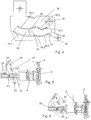
- Fig. 1 und 2
- je eine Ansicht eines Brühmoduls im geöffneten und im geschlossenen Zustand;
- Fig. 3
- eine Explosionsdarstellung des Brühmoduls von
Fig. 1 ;und 2 - Fig. 4
- eine Kurvenscheibe des Brühmoduls von
Fig. 1-3 ; - Fig. 5 und 6
- je eine vereinfachte Schnittdarstellung des Brühmoduls während des Schliess- bzw. Öffnungsvorgangs;
- Fig. 7-9
- je ein Detail einer Schnittdarstellung des Brühmoduls, welche die Dämpfungseinrichtung gut sichtbar macht, während unterschiedlichen Phasen; und
- Fig. 10
- ein Schema einer erfindungsgemässen Kaffeemaschine.
- Fig. 1 and 2
- one view of a brewing module in the open and in the closed state;
- Fig. 3
- an exploded view of the brewing module of
Fig. 1 and 2 ; - Fig. 4
- a cam of the brewing module of
Fig. 1-3 ; - FIGS. 5 and 6
- each a simplified sectional view of the brewing module during the closing or opening operation;
- Fig. 7-9
- depending on a detail of a sectional view of the brewing module, which makes the damping device clearly visible, during different phases; and
- Fig. 10
- a diagram of a coffee machine according to the invention.
Das Brühmodul 1 gemäss
Der Injektor 4 weist Perforationselemente zum Anstechen einer Portionskapsel auf, die mindestens teilweise mit einem Extraktionsgut - bspw. gemahlenem Kaffee - gefüllt ist. Der Injektor 4 ist eingerichtet, eine Flüssigkeit - bspw. heisses Wasser - durch die Perforationselemente oder an diesen vorbei in die angestochene Kapsel einzubringen wobei das Wasser über eine Wasserzuführung (nicht gezeigt) zuführbar ist, die bspw. einen flexiblen Schlauch aufweisen kann.The
Auch die Ausleitvorrichtung 3 weist im hier beschriebenen Ausführungsbeispiel Perforationselemente auf, nämlich extraktionsseitige Anstechspitzen. Diese können beispielsweise ausgebildet sein wie in
Für die Zubereitung eines Brühgetränks wird wie an sich bekannt eine Kapsel zwischen der Ausleitvorrichtung 3 und dem Injektor 4 platziert, und diese werden so aufeinander zubewegt, dass zwischen diesen eine die Kapsel umfassende Brühkammer gebildet wird. Das heisse Wasser wird durch den Injektor unter Druck der Kapsel zugeführt, und das Extraktionsprodukt fliesst durch die Ausleitvorrichtung 3 via einen Getränkeauslauf 13 in ein bspw. darunter platziertes Trinkgefäss ab.For the preparation of a brewing beverage, as is known, a capsule is placed between the
Die relative Bewegung des zweiten Brühmodulteils (Injektor) relativ zum ersten Brühmodulteil (Ausleitvorrichtung) wird im hier beschriebenen Ausführungsbeispiel dadurch erreicht, dass die Ausleitvorrichtung 3 gehäusefest montiert ist, während der Injektor 4 entlang der horizontalen Achse bewegbar ist.The relative movement of the second brewing module part (injector) relative to the first brewing module part (discharge device) is achieved in the exemplary embodiment described here in that the
Vor der Zubereitung eines Brühgetränks legt der Benutzer über eine am Gehäuse oberseitig angeordnete Kapseleinlegeöffnung eine Kapsel ein, die durch entsprechende Mittel, bspw. wie in
Für die Bedienung durch den Benutzer zwecks Schliessen der Brühkammer weist das Brühmodul einen Bedienhebel 6 auf, der fest mit einer aus zwei Kurvenscheiben 30 zusammengesetzten Kurvenscheibenanordnung befestigt ist. Die Kurvenscheiben ihrerseits sind um je einen Drehzapfen 31, welcher in je einer Bohrung 32 im entsprechenden Gehäuse-Seitenteil 21 und in der entsprechenden Kurvenscheibe 30 angeordnet ist, relativ zum Gehäuse schwenkbar gelagert. Über einen ersten und einen zweiten optionalen Stabilisierungsstift 45, 46 sind die beiden Kurvenscheiben 30 miteinander verbunden, um der Kurvenscheibenanordnung zusätzliche Stabilität zu verleihen. Für den ersten Führungsstift 45 ist in den beiden Gehäuse-Seitenteilen 21 je eine zweite Gehäuse-Führungsbahn 25 angeordnet, in welcher der erste Führungsstift 45 bei einer Schwenkbewegung der Kurvenscheibenanordnung lose oder geführt bewegt werden kann.For operation by the user for the purpose of closing the brewing chamber, the brewing module has an operating
An den Gehäuse-Seitenteilen 21 ist ausserdem je eine erste horizontale erste Gehäuse-Führungsbahn 22 ausgebildet, welche die gehäusefeste Verschiebungsstrecke definiert. Ein Führungsstift 41, der fest mit dem zweiten Brühmodulteil 4 verbunden ist, greift durch die Gehäuse-Führungsbahn 22 hindurch in je eine Führungsöffnung 33 der Kurvenscheiben 30 ein.On the
Der Führungsstift weist ein zu diesem Zweck hier beidseitig je ein erstes Gleitlager 42 und ein von diesem rotationsmässig entkoppeltes zweites Gleitlager 43 auf. Das erste Gleitlager 42 steht mit der Gehäuse-Führungsbahn 22 im Eingriff, während das zweite Gleitlager 43 in die entsprechende Führungsöffnung 33 ragt.The guide pin has a for this purpose here on both sides each have a first sliding
Aufgrund der von der Führungsöffnung gebildeten Führungsflächen wird eine Schwenkbewegung der Kurvenscheiben 30 bei Betätigung des Bedienhebels 6 in eine Verschiebebewegung des zweiten Brühmodulteils 4 entlang der von den Gehäuse-Führungsbahnen 22 definierten Verschiebungsstrecke umgesetzt.Due to the guide surfaces formed by the guide surfaces a pivoting movement of the
Wie insbesondere
Im dargestellten Ausführungsbeispiel weist die erste Führungsfläche 34 einen ersten Abschnitt 34.1 mit einem vergleichsweise grossen Übersetzungsverhältnis auf. In einem zweiten Abschnitt 34.2 wird ein deutlich kleineres Übersetzungsverhältnis definiert, damit der Benutzer beispielsweise beim Anstechen der Kapsel nicht zu viel Kraft benötigt. In einem dritten Abschnitt 34.3 ist das Übersetzungsverhältnis mittelgross. Im entsprechenden dritten Bereich der Verschiebungsstrecke werden bspw. die Anstechspitzen ganz in die Kapsel eingeführt und wird ggf. die Kapsel zwischen den Brühmodulteilen leicht komprimiert, weshalb ein mittelgrosser Kraftaufwand benötigt wird. Der Übergang von einem kleinen zu einem mittelgrossen Übersetzungsverhältnis zwischen dem zweiten und dem dritten Abschnitt (der für den Benutzer spürbare Widerstand pro Verschiebungsstrecke nimmt wieder zu) verhindert auch ein plötzliches Nachgeben nach dem erfolgten Anstechen; ein solches plötzliches Nachgeben wird vom Benutzer als Ruckeln wahrgenommen und kann sich aufgrund ruckartiger Belastungen auch negativ auf die Lebensdauer des Brühmoduls auswirken.In the illustrated embodiment, the
Zur Illustration: In einer Ausführungsform beträgt das Übersetzungsverhältnis im ersten Abschnitt zwischen 0.6 mm/° und 2.5 mm/° (das Übersetzungsverhältnis muss innerhalb des jeweiligen Abschnitts nicht konstant sein, sondern kann durchaus variieren), im zweiten Abschnitt zwischen 0.1 mm/° und 0.2 mm/° und im dritten Abschnitt zwischen 0.2 mm/° und 0.4 mm/°. Beispielsweise wird durch den ersten Abschnitt das zweite Brühmodulteil innerhalb vom ca. 30° Hebelbewegung ca. 25 mm nach vorne geschoben, im zweiten Abschnitt innerhalb von 15° Hebelbewegung um 2-3 mm und im dritten Abschnitt innerhalb von 40° Hebelbewegung um 10-12 mm. Selbstverständlich sind auch ganz andere Zahlenwerte möglich, das Optimum hängt von der konkreten Geometrie, den gewählten Materialien und gegebenenfalls auch der Dämpfungseinrichtung ab. Auf jeden Fall ist der Unterschied zwischen den verschiedenen Übersetzungsverhältnissen entlang des Wegs substantiell.By way of illustration: In one embodiment, the gear ratio in the first section is between 0.6 mm / ° and 2.5 mm / ° (the gear ratio does not have to be constant within the respective section but can vary), in the second section between 0.1 mm / ° and 0.2 mm / ° and in the third section between 0.2 mm / ° and 0.4 mm / °. For example, the second brewing module part is pushed forward approximately 25 mm by the first section within approximately 30 ° lever movement, by 2-3 mm in the second section within 15 ° lever movement and by 10-12 in the third section within 40 ° lever movement mm. Of course, completely different numerical values are possible, the optimum depends on the specific geometry, the selected materials and possibly also the damping device. In any case, the difference between the different gear ratios along the way is substantial.
Die zweite Führungsfläche 35 weist für den umgekehrten Weg ebenfalls drei Abschnitte auf. Ein erster Abschnitt 35.1 mit einem mittelgrossen Übersetzungsverhältnis dient dem anfänglichen Öffnen der Brühkammer und dem ersten Schritt im Prozess des Entfernens der Kapsel. In einem zweiten Abschnitt 35.2 ist das Übersetzungsverhältnis klein, weil beispielsweise eine grosse Kraft nötig ist, um die Kapsel unter Deformation weiter herauszuziehen, so dass sie anschliessend nach untern fallen kann. In einem dritten Abschnitt 35.3 ist das Übersetzungsverhältnis gross, so dass zum genügend weiten Öffnen der Brühkammer bei kleinem mechanischem Widerstand kein zu grosser Weg des Bedienelements nötig ist.The
Die Übersetzungsverhältnisse und durch die zweite Führungsfläche bewirkten zurückgelegten Wege können ungefähr den Werten der ersten Führungsfläche entsprechen, wobei der dritte Abschnitt der ersten Führungsfläche dem ersten Abschnitt der zweiten Führungsfläche entspricht, die zweiten Abschnitte einander entsprechen und der erste Abschnitt der ersten Führungsfläche dem dritten Abschnitt der zweiten Führungsfläche entspricht.The gear ratios and paths traveled by the second guide surface may correspond approximately to the values of the first guide surface, wherein the third portion of the first guide surface corresponds to the first portion of the second guide surface, the second portions correspond to each other, and the first portion of the first guide surface corresponds to the third portion of the first guide surface second guide surface corresponds.
In der
Ein spezielles optionales Merkmal ist in
Das Dämpfungsorgan weist ein elastisches Element - hier einen Dämpfungsring 53, der sich um eine Führungspartie 58 herum erstreckt - auf. Der Dämpfungsring ist in einer dafür vorgesehene Aufnahme 54 angeordnet und in dieser teilweise bewegbarThe damping member has an elastic element - here a damping
In
Während der Öffnungsbewegung (
Wenn sich der Dämpfungsring 53 während Schliessbewegung während der Annäherung an die Gleitfläche 51 ausserhalb der Verengung 55 befindet, sorgt eine optionale Schrägfläche 56 zusammen mit der intrinsischen Elastizität des Dämpfungsringes und dessen in-Kontakt-Kommen mit der Gleitfläche 51 dafür, dass der Dämpfungsring während der in
Anstelle eines Dämpfungsring kann auch ein andere beispielsweise elastisches Dämpfungselement verwendet werden, bspw. eine elastische Lippe. Bevorzugt ist das Dämpfungselement so angeordnet und ausgebildet, dass es, wenn es mit der Gleitfläche in Kontakt kommt, durch eine Bewegung relativ zur Gleitfläche in die eine Richtung deformiert wird und eine elastische, der Deformation entgegenwirkende Kraft auf die Gleitfläche ausübt, während es bei einer Bewegung in die andere Richtung ausweichen kann und im wesentlichen kraftfrei der Gleitfläche entlanggleiten kann. Bei einer elastischen Lippe wird das dadurch erreicht, dass die Lippe nicht senkrecht zur Gleitfläche steht sondern in einem nicht-rechten Winkel dazu.Instead of a damping ring and another example, elastic damping element can be used, for example. An elastic lip. Preferably, the damping element is arranged and formed so that, when it comes into contact with the sliding surface, by a movement relative to the sliding surface in the a direction is deformed and exerts an elastic, the deformation-counteracting force on the sliding surface, while it can escape when moving in the other direction and slide substantially force-free sliding surface. In the case of an elastic lip, this is achieved in that the lip is not perpendicular to the sliding surface but at a non-right angle thereto.
Eine erfindungsgemässe Maschine zum Zubereiten eines Brühgetränks aus einer Portionskapsel 10, nämlich hier eine Kaffeemaschine, mit einem Brühmodul 1 ist in
- 11
- Brühmodulbrewing module
- 22
- BrühmodulgehäuseBrühmodulgehäuse
- 33
- Ausleitvorrichtungdiversion
- 44
- Injektorinjector
- 66
- Bedienhebeloperating lever
- 1313
- Getränkeauslaufbeverage outlet
- 2121
- Gehäuse-SeitenteilHousing side part
- 2222
- Erste Gehäuse-FührungsbahnFirst housing guideway
- 2525
- Zweite Gehäuse-FührungsbahnSecond housing guideway
- 3030
- Kurvenscheibecam
- 3131
- Drehzapfenpivot
- 3232
- Bohrungen für DrehzapfenHoles for trunnions
- 3333
- Führungsöffnungguide opening
- 3434
- erste Führungsflächefirst guide surface
- 34.134.1
- erster Abschnittfirst section
- 34.234.2
- zweiter Abschnittsecond part
- 34.334.3
- dritter Abschnittthird section
- 3535
- zweite Führungsflächesecond guide surface
- 35.135.1
- erster Abschnittfirst section
- 35.235.2
- zweiter Abschnittsecond part
- 35.335.3
- dritter Abschnittthird section
- 3636
- End-AbschnittEnd section
- 3737
- Absatzparagraph
- 3838
- Krafteinleitung beim BrühenForce application during brewing
- 4141
- Führungsstiftguide pin
- 4242
- erste Gleitlagerfirst plain bearing
- 4343
- zweite Gleitlagersecond sliding bearing
- 4545
- erster Stabilisierungsstiftfirst stabilizing pin
- 4646
- zweiter Stabilisierungsstiftsecond stabilizing pin
- 5151
- Gleitflächesliding surface
- 5252
- Dämpfungsorgandamping element
- 5353
- Dämpfungsringdamping ring
- 5454
- Aufnahmeadmission
- 5555
- Verengungnarrowing
- 5656
- Schrägflächesloping surface
- 5858
- Führungspartieguiding part
- 6060
- Bewegungsrichtungmovement direction
- 9191
- Wassertankwater tank
- 9292
- Pumpepump
- 9393
- WasserheizungsvorrichtungWater heating device
- 9595
- Kapselbehältercapsule container
- 9898
- Kaffeetassecoffee pot
Claims (15)
Priority Applications (13)
| Application Number | Priority Date | Filing Date | Title |
|---|---|---|---|
| EP17172058.4A EP3403546A1 (en) | 2017-05-19 | 2017-05-19 | Brewing module and machine for making beverages |
| PT187261037T PT3624651T (en) | 2017-05-19 | 2018-05-16 | Brewing module and beverage-preparing machine |
| CN201880032522.6A CN110662467B (en) | 2017-05-19 | 2018-05-16 | Brewing module and beverage preparation machine |
| KR1020197034710A KR20200033795A (en) | 2017-05-19 | 2018-05-16 | Brewing module and beverage preparation machine |
| PL18726103.7T PL3624651T3 (en) | 2017-05-19 | 2018-05-16 | Brewing module and machine for making beverages |
| CA3062587A CA3062587A1 (en) | 2017-05-19 | 2018-05-16 | A brewing module and drinks preparation machine |
| AU2018269499A AU2018269499A1 (en) | 2017-05-19 | 2018-05-16 | Brewing module and beverage-preparing machine |
| JP2019563896A JP2020520712A (en) | 2017-05-19 | 2018-05-16 | Brewing module and beverage preparation machine |
| EP18726103.7A EP3624651B1 (en) | 2017-05-19 | 2018-05-16 | Brewing module and machine for making beverages |
| HUE18726103A HUE060585T2 (en) | 2017-05-19 | 2018-05-16 | Brewing module and machine for making beverages |
| US16/613,585 US11337540B2 (en) | 2017-05-19 | 2018-05-16 | Brewing module and drinks preparation machine |
| RU2019135702A RU2763234C2 (en) | 2017-05-19 | 2018-05-16 | Brewing module and machine for making beverages |
| PCT/EP2018/062650 WO2018210899A1 (en) | 2017-05-19 | 2018-05-16 | Brewing module and beverage-preparing machine |
Applications Claiming Priority (1)
| Application Number | Priority Date | Filing Date | Title |
|---|---|---|---|
| EP17172058.4A EP3403546A1 (en) | 2017-05-19 | 2017-05-19 | Brewing module and machine for making beverages |
Publications (1)
| Publication Number | Publication Date |
|---|---|
| EP3403546A1 true EP3403546A1 (en) | 2018-11-21 |
Family
ID=58738984
Family Applications (2)
| Application Number | Title | Priority Date | Filing Date |
|---|---|---|---|
| EP17172058.4A Withdrawn EP3403546A1 (en) | 2017-05-19 | 2017-05-19 | Brewing module and machine for making beverages |
| EP18726103.7A Active EP3624651B1 (en) | 2017-05-19 | 2018-05-16 | Brewing module and machine for making beverages |
Family Applications After (1)
| Application Number | Title | Priority Date | Filing Date |
|---|---|---|---|
| EP18726103.7A Active EP3624651B1 (en) | 2017-05-19 | 2018-05-16 | Brewing module and machine for making beverages |
Country Status (12)
| Country | Link |
|---|---|
| US (1) | US11337540B2 (en) |
| EP (2) | EP3403546A1 (en) |
| JP (1) | JP2020520712A (en) |
| KR (1) | KR20200033795A (en) |
| CN (1) | CN110662467B (en) |
| AU (1) | AU2018269499A1 (en) |
| CA (1) | CA3062587A1 (en) |
| HU (1) | HUE060585T2 (en) |
| PL (1) | PL3624651T3 (en) |
| PT (1) | PT3624651T (en) |
| RU (1) | RU2763234C2 (en) |
| WO (1) | WO2018210899A1 (en) |
Families Citing this family (2)
| Publication number | Priority date | Publication date | Assignee | Title |
|---|---|---|---|---|
| CN111132588A (en) * | 2017-09-25 | 2020-05-08 | 雀巢产品有限公司 | Beverage machine with removable module |
| US11636334B2 (en) | 2019-08-20 | 2023-04-25 | Micron Technology, Inc. | Machine learning with feature obfuscation |
Citations (8)
| Publication number | Priority date | Publication date | Assignee | Title |
|---|---|---|---|---|
| EP1859713A1 (en) * | 2006-05-24 | 2007-11-28 | Nestec S.A. | Brewing device for capsule with closure mechanism of variable transmission ratio |
| WO2010118544A2 (en) | 2009-04-15 | 2010-10-21 | Luna Technology Systems Lts Gmbh | Device for discharging an extraction product out of a portion packaging; puncturing device and extraction apparatus |
| EP2485629A2 (en) | 2009-10-05 | 2012-08-15 | Nestec S.A. | Ergonomic capsule extraction device |
| US20150017288A1 (en) * | 2013-07-15 | 2015-01-15 | La Vit Technology Llc | Capsule based system for preparing and dispensing a beverage |
| US20150013279A1 (en) * | 2013-07-10 | 2015-01-15 | Keurig Green Mountain, Inc. | Beverage machine cartridge holder with damped movement |
| WO2015039258A1 (en) | 2013-09-20 | 2015-03-26 | Luna Technology Systems Lts Gmbh | Perforation device for extraction appliances for producing brewed products |
| WO2015048914A1 (en) | 2013-10-01 | 2015-04-09 | Luna Technology Systems Lts Gmbh | Brewing module |
| WO2016087190A1 (en) | 2014-12-01 | 2016-06-09 | Qbo Coffee Gmbh | Brewing module, capsule-detecting module, and beverage-preparing machine |
Family Cites Families (11)
| Publication number | Priority date | Publication date | Assignee | Title |
|---|---|---|---|---|
| ES2319679T5 (en) * | 2006-05-24 | 2014-11-27 | Nestec S.A. | Capsule drilling module |
| CN200960050Y (en) * | 2006-10-12 | 2007-10-17 | 广东亿龙电器股份有限公司 | Driving apparatus for coffee machine |
| IT1395966B1 (en) * | 2009-08-03 | 2012-11-02 | Torino Politecnico | MACHINE FOR THE PREPARATION OF DRINKS BY MEANS OF THE INFUSION OF A PRODUCT CONTAINED IN A CAPSULE OR LIKE |
| CA2776298C (en) * | 2009-10-05 | 2017-08-22 | Nestec S.A. | Cartridge extraction device |
| EP2505109A1 (en) * | 2011-03-30 | 2012-10-03 | Celaya, Emparanza Y Galdos Internacional, S.A. | Coffee maker with trolley |
| EP2717748B1 (en) * | 2011-06-09 | 2015-07-22 | Luigi Lavazza S.p.A. | Delivery assembly for machines for preparing liquid products via cartridges |
| RU2014138922A (en) * | 2012-02-28 | 2016-04-20 | Нестек С.А. | CAPSULE AUTOMATIC BREWER |
| HUE050271T2 (en) * | 2013-01-28 | 2020-11-30 | Tchibo Gmbh | Brewing module |
| CN105263375A (en) * | 2013-04-03 | 2016-01-20 | 2266170安大略公司 | Capsule machine and components |
| ES2572646T3 (en) * | 2013-07-31 | 2016-06-01 | Rheavendors Services S.P.A. | Procedure and apparatus for preparing and distributing coffee |
| EP3116805B1 (en) * | 2014-03-12 | 2018-07-04 | Sarong Societa' Per Azioni | Capsule for beverages |
-
2017
- 2017-05-19 EP EP17172058.4A patent/EP3403546A1/en not_active Withdrawn
-
2018
- 2018-05-16 JP JP2019563896A patent/JP2020520712A/en active Pending
- 2018-05-16 KR KR1020197034710A patent/KR20200033795A/en active IP Right Grant
- 2018-05-16 HU HUE18726103A patent/HUE060585T2/en unknown
- 2018-05-16 US US16/613,585 patent/US11337540B2/en active Active
- 2018-05-16 CA CA3062587A patent/CA3062587A1/en not_active Abandoned
- 2018-05-16 WO PCT/EP2018/062650 patent/WO2018210899A1/en active Application Filing
- 2018-05-16 AU AU2018269499A patent/AU2018269499A1/en not_active Abandoned
- 2018-05-16 CN CN201880032522.6A patent/CN110662467B/en active Active
- 2018-05-16 PL PL18726103.7T patent/PL3624651T3/en unknown
- 2018-05-16 RU RU2019135702A patent/RU2763234C2/en active
- 2018-05-16 EP EP18726103.7A patent/EP3624651B1/en active Active
- 2018-05-16 PT PT187261037T patent/PT3624651T/en unknown
Patent Citations (9)
| Publication number | Priority date | Publication date | Assignee | Title |
|---|---|---|---|---|
| EP1859713A1 (en) * | 2006-05-24 | 2007-11-28 | Nestec S.A. | Brewing device for capsule with closure mechanism of variable transmission ratio |
| WO2010118544A2 (en) | 2009-04-15 | 2010-10-21 | Luna Technology Systems Lts Gmbh | Device for discharging an extraction product out of a portion packaging; puncturing device and extraction apparatus |
| EP2485629A2 (en) | 2009-10-05 | 2012-08-15 | Nestec S.A. | Ergonomic capsule extraction device |
| EP2485629B1 (en) * | 2009-10-05 | 2014-01-08 | Nestec S.A. | Ergonomic capsule extraction device |
| US20150013279A1 (en) * | 2013-07-10 | 2015-01-15 | Keurig Green Mountain, Inc. | Beverage machine cartridge holder with damped movement |
| US20150017288A1 (en) * | 2013-07-15 | 2015-01-15 | La Vit Technology Llc | Capsule based system for preparing and dispensing a beverage |
| WO2015039258A1 (en) | 2013-09-20 | 2015-03-26 | Luna Technology Systems Lts Gmbh | Perforation device for extraction appliances for producing brewed products |
| WO2015048914A1 (en) | 2013-10-01 | 2015-04-09 | Luna Technology Systems Lts Gmbh | Brewing module |
| WO2016087190A1 (en) | 2014-12-01 | 2016-06-09 | Qbo Coffee Gmbh | Brewing module, capsule-detecting module, and beverage-preparing machine |
Also Published As
| Publication number | Publication date |
|---|---|
| EP3624651B1 (en) | 2022-08-24 |
| EP3624651A1 (en) | 2020-03-25 |
| US20200060464A1 (en) | 2020-02-27 |
| WO2018210899A1 (en) | 2018-11-22 |
| RU2019135702A (en) | 2021-06-21 |
| US11337540B2 (en) | 2022-05-24 |
| PT3624651T (en) | 2022-11-29 |
| RU2763234C2 (en) | 2021-12-28 |
| PL3624651T3 (en) | 2023-01-16 |
| JP2020520712A (en) | 2020-07-16 |
| CA3062587A1 (en) | 2019-11-06 |
| AU2018269499A1 (en) | 2019-12-05 |
| KR20200033795A (en) | 2020-03-30 |
| CN110662467B (en) | 2021-12-21 |
| RU2019135702A3 (en) | 2021-08-12 |
| CN110662467A (en) | 2020-01-07 |
| HUE060585T2 (en) | 2023-04-28 |
Similar Documents
| Publication | Publication Date | Title |
|---|---|---|
| EP2105074B1 (en) | Device and array for preparing a liquid food or luxury article and portion packaging | |
| EP1133944B1 (en) | Espresso coffee machine | |
| AT504054B1 (en) | DEVICE FOR CUSHIONING OR BZW. BREAKDOWN OF MOVABLE FURNITURE PARTS OF FURNITURE PIECES | |
| DE60301211T2 (en) | DISTRIBUTION HEAD TO ARRANGE TO A HOLLOW, MOVABLE ACTUATOR | |
| EP3280300B1 (en) | Beverage preparation machine | |
| EP2948031B1 (en) | Brewing module | |
| DE3400356C2 (en) | ||
| EP3624651B1 (en) | Brewing module and machine for making beverages | |
| CH710946A1 (en) | Brewing device with two brewing chambers. | |
| EP2807963B1 (en) | Espresso coffee machine with a brewing unit | |
| DE2930204A1 (en) | SELF-CLOSING VALVE | |
| DE10334526B4 (en) | Coffee brewing device with locked filter carrier | |
| DE102007060813A1 (en) | Automatic coffee machine, for espresso coffee, has a cylinder with a sliding piston with a perforated curved surface and a closing piston | |
| EP3624650B1 (en) | Brewing module and machine for making beverages | |
| EP3373778B1 (en) | Collecting container for collecting insoluble material used during the preparation of beverages, and infusion device comprising such a collecting container | |
| DE102010060291A1 (en) | Cover for a beverage container | |
| EP3545801B1 (en) | Beverage machine with draining means for residual water | |
| EP0054717A1 (en) | Arrangement for delivering gas | |
| WO2016079672A1 (en) | Brewing head for an espresso machine | |
| DE60204837T2 (en) | coffee machine | |
| DE102015209991B4 (en) | Hot beverage preparation device | |
| EP3017729A1 (en) | Brewing element for a beverage preparation device | |
| DE3811675A1 (en) | Device for preventing the opening of a pressure cooker which is under pressure | |
| EP3120739B1 (en) | Brewing device and hot beverage preparation device | |
| EP3932269A1 (en) | Brewing unit for reducing the residual water during the rinsing process and method for operating a brewing unit |
Legal Events
| Date | Code | Title | Description |
|---|---|---|---|
| PUAI | Public reference made under article 153(3) epc to a published international application that has entered the european phase |
Free format text: ORIGINAL CODE: 0009012 |
|
| STAA | Information on the status of an ep patent application or granted ep patent |
Free format text: STATUS: THE APPLICATION HAS BEEN PUBLISHED |
|
| AK | Designated contracting states |
Kind code of ref document: A1 Designated state(s): AL AT BE BG CH CY CZ DE DK EE ES FI FR GB GR HR HU IE IS IT LI LT LU LV MC MK MT NL NO PL PT RO RS SE SI SK SM TR |
|
| AX | Request for extension of the european patent |
Extension state: BA ME |
|
| STAA | Information on the status of an ep patent application or granted ep patent |
Free format text: STATUS: THE APPLICATION IS DEEMED TO BE WITHDRAWN |
|
| 18D | Application deemed to be withdrawn |
Effective date: 20190522 |