EP3403546A1 - Module d'ébouillantage et machine de préparation de boissons - Google Patents
Module d'ébouillantage et machine de préparation de boissons Download PDFInfo
- Publication number
- EP3403546A1 EP3403546A1 EP17172058.4A EP17172058A EP3403546A1 EP 3403546 A1 EP3403546 A1 EP 3403546A1 EP 17172058 A EP17172058 A EP 17172058A EP 3403546 A1 EP3403546 A1 EP 3403546A1
- Authority
- EP
- European Patent Office
- Prior art keywords
- brewing module
- brewing
- movement
- housing
- damping
- Prior art date
- Legal status (The legal status is an assumption and is not a legal conclusion. Google has not performed a legal analysis and makes no representation as to the accuracy of the status listed.)
- Withdrawn
Links
Images


Classifications
-
- A—HUMAN NECESSITIES
- A47—FURNITURE; DOMESTIC ARTICLES OR APPLIANCES; COFFEE MILLS; SPICE MILLS; SUCTION CLEANERS IN GENERAL
- A47J—KITCHEN EQUIPMENT; COFFEE MILLS; SPICE MILLS; APPARATUS FOR MAKING BEVERAGES
- A47J31/00—Apparatus for making beverages
- A47J31/24—Coffee-making apparatus in which hot water is passed through the filter under pressure, i.e. in which the coffee grounds are extracted under pressure
- A47J31/34—Coffee-making apparatus in which hot water is passed through the filter under pressure, i.e. in which the coffee grounds are extracted under pressure with hot water under liquid pressure
- A47J31/36—Coffee-making apparatus in which hot water is passed through the filter under pressure, i.e. in which the coffee grounds are extracted under pressure with hot water under liquid pressure with mechanical pressure-producing means
- A47J31/3604—Coffee-making apparatus in which hot water is passed through the filter under pressure, i.e. in which the coffee grounds are extracted under pressure with hot water under liquid pressure with mechanical pressure-producing means with a mechanism arranged to move the brewing chamber between loading, infusing and ejecting stations
- A47J31/3623—Cartridges being employed
- A47J31/3633—Means to perform transfer from a loading position to an infusing position
-
- A—HUMAN NECESSITIES
- A47—FURNITURE; DOMESTIC ARTICLES OR APPLIANCES; COFFEE MILLS; SPICE MILLS; SUCTION CLEANERS IN GENERAL
- A47J—KITCHEN EQUIPMENT; COFFEE MILLS; SPICE MILLS; APPARATUS FOR MAKING BEVERAGES
- A47J31/00—Apparatus for making beverages
- A47J31/24—Coffee-making apparatus in which hot water is passed through the filter under pressure, i.e. in which the coffee grounds are extracted under pressure
- A47J31/34—Coffee-making apparatus in which hot water is passed through the filter under pressure, i.e. in which the coffee grounds are extracted under pressure with hot water under liquid pressure
- A47J31/36—Coffee-making apparatus in which hot water is passed through the filter under pressure, i.e. in which the coffee grounds are extracted under pressure with hot water under liquid pressure with mechanical pressure-producing means
- A47J31/3604—Coffee-making apparatus in which hot water is passed through the filter under pressure, i.e. in which the coffee grounds are extracted under pressure with hot water under liquid pressure with mechanical pressure-producing means with a mechanism arranged to move the brewing chamber between loading, infusing and ejecting stations
- A47J31/3647—Coffee-making apparatus in which hot water is passed through the filter under pressure, i.e. in which the coffee grounds are extracted under pressure with hot water under liquid pressure with mechanical pressure-producing means with a mechanism arranged to move the brewing chamber between loading, infusing and ejecting stations a tape being employed
- A47J31/3652—Coffee-making apparatus in which hot water is passed through the filter under pressure, i.e. in which the coffee grounds are extracted under pressure with hot water under liquid pressure with mechanical pressure-producing means with a mechanism arranged to move the brewing chamber between loading, infusing and ejecting stations a tape being employed the tape including only filtering means, i.e. not including brewing material
Definitions
- the invention relates to extraction devices for preparing beverages or the like from an extraction material contained in a portion capsule, for example ground coffee. It relates in particular to a brewing module for an extraction device, a capsule recognition module and a beverage preparation machine with such a brewing module and / or capsule recognition module.
- Extraction devices for preparing beverages or the like from an extraction material present in a portion package are known, for example, as coffee or espresso machines.
- the portion packages are designed as capsules, in which the extraction material, for example, is airtight.
- the capsule is pierced, for example on two opposite sides. On the first side then an extraction liquid - generally hot water - is introduced. On the second side, the extraction product is discharged from the capsule. This happens in a so-called brewing module.
- brewing module Such has a brewing chamber in which the capsule is received.
- Brewing modules in which the capsule is inserted and the brewing chamber is manually closed by means of an operating lever are particularly popular, the capsule being automatically removed from the brewing chamber and ejected into a capsule container when the brewing chamber is opened again after the brewing process.
- Such brewing modules with automatic capsule ejection are generally designed as horizontal brewing modules, ie the capsule is inserted from above, the closure of the brewing chamber is a horizontal relative movement of two brewing module parts, the brewing liquid flows substantially horizontally, and the capsule container is formed below the brewing chamber.
- a damping device for damping a closing or opening movement of a brewing module is for example already out of EP 2 485 629 known. This is related to a spring drive during the opening movement and serves in particular to prevent that takes place at the end of the opening movement too violent striking a stop.
- the damping device can work on inertia and friction, but also on friction alone, hydraulically, by air damping, magnetic, etc. and generally attenuates the closing and the opening movement evenly.
- the brewing module has a damping device for damping the movement of the second brewing module part.
- the damping device is designed so that it has a non-constant in function of the position and / or direction of movement damping characteristic.
- the movement of the second brewing module part from the first to the second position is also called “closing movement” and the reverse movement is called “opening movement”.
- the damping device may be designed such that it only attenuates along a partial path of the displacement path and / or only during the closing movement or only during the opening movement.
- the inventive approach allows for non-constant mechanical resistance during the closing process or during the opening process attenuation takes place deliberately there or occurs where the resistance decreases abruptly as a function of the path of the second Brühmodulteils.
- the damping device can prevent jerking, which can not only have a positive effect on the perception by the user, but also on the life of the brewing module by jerky movements are avoided.
- the damping device can be formed in that two relatively moving parts of the brewing module - for example.
- a cam and the housing or the second Brühmodulteil and the housing - each have a contact portion, which come into physical contact with each other only on a leg of the displacement distance and rub against each other.
- Such contact parts can be formed, for example, by a sliding surface on the one hand and an elastic damping element on the other hand.
- the one of the contact parts is formed by a damping element, which in the closing movement and during the opening movement in different degrees against the other Contact part is pressed - especially at the opening movement or during the closing movement not at all.
- the damping element may be formed as an elastic element, which is movably received in a receptacle of the corresponding part of the brewing module, being pressed against the other contact part during one movement (eg during the closing movement). This may, for example, be effected, for example, by the receptacle towards the direction in which the damping element is pressed during a movement, having a constriction, in which the damping element is compressed between the two parts, while during the opening movement of the other contact portion can dodge away.
- the damping element may, for example, be designed as an elastic ring (damping ring). Instead of a damping ring and another example, elastic damping element can be used, for example. An elastic lip or an elastically deformable cushion.
- the damping element is arranged and formed so that when it comes into contact with the sliding surface, it is deformed by a movement relative to the sliding surface in one direction and exerts an elastic, deformation-opposing force on the sliding surface, while at a Movement can dodge in the other direction and can slide along the sliding surface substantially force-free.
- a damping element which is clamped during movement in one of the directions of movement in a constriction, such a deformation is effected by compression of the damping element.
- the lip is not perpendicular to the Sliding surface is but at a non-right angle to, ie it projects obliquely to the sliding surface and to the side, in which they in the closing movement (when this is to be damped in a section) or during the opening movement is moved.
- the housing has a sliding surface which projects toward the second brewing module part or to another element moving during its movement, for example a cam of the transmission mechanism, and in that the moving element (brewing module part, cam, other element) a damping element, which is pressed due to an elastic force and / or due to jamming on the leg and / or in at least one direction of movement against the sliding surface - or vice versa.
- Such a sliding surface may have a varying distance to the damping element as a function of the position, so that the friction force changes as a function of the position.
- a damping element may in particular be made of an elastomer.
- the transmission mechanism for transmitting the movement of the operating element may have a cam plate rotatably mounted on the housing with a first guide surface, wherein the second Brühmodulteil is displaced by the first guide surface along a housing-fixed displacement distance from the first Brühmodulteil position to the second Brühmodulteil position by the Cam is rotated, and that the first guide surface along the first guide surface significantly (for example, by at least a factor of 2) varying transmission ratio (ratio between the second Brühmodulteil distance traveled on the one hand and the distance traveled by the cam angular movement on the other hand) defined.
- the transmission ratio varies significantly. In embodiments, it differs between the largest and the smallest value by at least a factor of 2, often by at least a factor of 4, 6, 8, 10 or more.
- the gear ratio may in particular be selected so that it is smaller at a larger closing force than where the closing force is small.
- the cam disc can also define a second guide surface, by which the second brewing module part is displaceable along the housing-fixed displacement path from the second brewing module part position into the first brewing module part position.
- a second guide surface can in particular also run in such a way that a variable transmission ratio is defined along it, for example likewise in sections, and also substantially, for example, with a factor between the largest and the smallest transmission ratio of at least 2, or at least a factor of 4, 6. 8, 10 or more.
- the first and second guide surfaces may be formed as boundaries of a guide hole in the cam (such opening may be a through hole or a recess).
- An example, pin-like guide element which is connected to the second Brühmodulteil, for example. By being molded on this or is guided by this, then engages in this guide opening.
- the second guide surface may be non-parallel to the first guide surface, i. It is not necessary that the transmission ratios at a certain position of the second Brühmodulteils during the closing and the opening movement are equal.
- the second brewing module part is for example linear-translatory, in particular horizontally movable relative to the housing, i. the displacement distance is in particular linear and horizontal.
- the first brewing module part can be mounted fixed to the housing. However, it is also possible that the first brewing module part is also movable and, for example, makes a movement opposite to the second brewing module part.
- the housing-fixed displacement section can be defined, for example, by a guide track, for example a guide groove, of the housing into which a guide element connected to the second brewing module part, for example a guide pin, engages.
- a guide element can also interact with the guide surface, wherein then a portion of the guide element engages in the guide track and another portion cooperates with the guide surface.
- a guide element may optionally be provided with two mutually decoupled bearings, one of which is in engagement with the guide track and a second with the guide surface.
- the second brewing module part may be an injector, through which the portion capsule is pierced and from which, for example, hot water is introduced as brewing liquid into the portion capsule.
- the first brewing module part may form a discharge device for discharging the extraction product from the capsule.
- it has extraction-side piercing elements for the extraction-side piercing of the capsule or other structures, which open the capsule on the extraction side.
- the first brewing module part can form the injector and the second brewing module part the discharge device.
- the operating element may in particular be an operating lever which can be brought from the first to the second position by a tilting movement from top to bottom. In the second position, for example, the operating lever closes a capsule insertion opening, which is formed by a housing of the beverage preparation machine-for example, the brewing module.
- the invention also relates to a beverage preparation machine with a brewing module of the type discussed.
- the brewing module 1 has a Brühmodulgephase. 2 In Brühmodulgephaseuse 2 two relatively movable Brühmodulmaschine be performed, namely a discharge device 3 and an injector 4.
- the housing has two housing side parts 21 here.
- the injector 4 has perforation elements for piercing a portion capsule, which is at least partially filled with an extraction material - for example, ground coffee.
- the injector 4 is set up to introduce a liquid-for example hot water-through the perforation elements or past them into the pierced capsule, wherein the water can be supplied via a water supply (not shown) which, for example, may have a flexible hose.
- the diverting device 3 has in the embodiment described here on perforation, namely extraction-side piercing tips. These may be formed, for example, as in WO 2015/039258 or in WO 2010/118544 described or have another embodiment; the use of other principles than piercing tips, for example. With lattice-like structures are possible.
- a capsule is placed between the discharge device 3 and the injector 4, and these are moved toward each other in such a way that a brewing chamber comprising the capsule is formed between them.
- the hot water is supplied through the injector under pressure of the capsule, and the extraction product flows through the Diversion device 3 via a beverage outlet 13 in an example. Below placed drinking vessel from.
- the relative movement of the second brewing module part (injector) relative to the first brewing module part (discharge device) is achieved in the exemplary embodiment described here in that the discharge device 3 is mounted fixed to the housing while the injector 4 is movable along the horizontal axis.
- the user Before the preparation of a brewing beverage, the user inserts a capsule via a capsule insertion opening arranged on the top side of the housing, which capsule is replaced by appropriate means, for example as in WO 2015/048914 is kept at the designated height until the brewing chamber is closed.
- Such insertion of the capsule in the brewing chamber can be done directly, or as, for example, in WO 2016/087190 described, indirectly, by the capsule is first held at a position above the brewing chamber, for example.
- a capsule recognition For the purpose of a capsule recognition.
- the brewing module For operation by the user for the purpose of closing the brewing chamber, the brewing module has an operating lever 6 which is fastened fixedly to a cam plate arrangement composed of two cams 30.
- the cams in turn are each pivotally mounted about a pivot 31 which is arranged in a respective bore 32 in the corresponding housing side part 21 and in the corresponding cam 30 relative to the housing.
- Via a first and a second optional stabilizing pin 45, 46 the two cams 30 are connected together to provide additional stability to the cam assembly.
- a second housing guide track 25 is respectively arranged in the two housing side parts 21, in which the first one Guide pin 45 can be moved loose or guided in a pivoting movement of the cam assembly.
- a first horizontal first housing guide rail 22 is also formed, which defines the housing-fixed displacement path.
- a guide pin 41 which is fixedly connected to the second Brühmodulteil 4, engages through the housing guide rail 22 through in each case a guide opening 33 of the cam 30 a.
- the guide pin has a for this purpose here on both sides each have a first sliding bearing 42 and a rotatably decoupled from this second sliding bearing 43.
- the first slide bearing 42 is engaged with the housing guide track 22, while the second slide bearing 43 projects into the corresponding guide opening 33.
- the guide opening 33 forms due to their shape a first guide surface 34 and a non-parallel to this second guide surface 35, which cause the displacement of the brewing module in the closing or during the opening movement.
- the non-constant gear ratio is caused by the fact that the guide surfaces describe a path that deviates from an Archimedean spiral with the bore 32 as the center.
- the first guide surface 34 has a first section 34.1 with a comparatively large transmission ratio.
- a significantly smaller gear ratio is defined so that the user does not need too much force, for example, when piercing the capsule.
- the transmission ratio is medium.
- the piercing tips are completely inserted into the capsule and, if appropriate, the capsule is slightly compressed between the brewing module parts, which is why a medium-sized effort is required.
- the transition from a small to a medium gear ratio between the second and third sections also prevents a sudden yielding after the piercing has occurred; such a sudden yielding is perceived by the user as stuttering and may also have a negative impact on the life of the brewing module due to jerky loads.
- the gear ratio in the first section is between 0.6 mm / ° and 2.5 mm / ° (the gear ratio does not have to be constant within the respective section but can vary), in the second section between 0.1 mm / ° and 0.2 mm / ° and in the third section between 0.2 mm / ° and 0.4 mm / °.
- the second brewing module part is pushed forward approximately 25 mm by the first section within approximately 30 ° lever movement, by 2-3 mm in the second section within 15 ° lever movement and by 10-12 in the third section within 40 ° lever movement mm.
- the optimum depends on the specific geometry, the selected materials and possibly also the damping device. In any case, the difference between the different gear ratios along the way is substantial.
- the second guide surface 35 also has three sections for the reverse path.
- a first section 35.1 with a medium gear ratio serves to initially open the brewing chamber and the first step in the process of removing the capsule.
- the gear ratio is small because, for example, a large force is needed to further pull out the capsule under deformation, so that it can then fall down.
- the transmission ratio is large, so that for sufficiently wide opening of the brewing chamber with a small mechanical resistance no excessive travel of the control element is necessary.
- the gear ratios and paths traveled by the second guide surface may correspond approximately to the values of the first guide surface, wherein the third portion of the first guide surface corresponds to the first portion of the second guide surface, the second portions correspond to each other, and the first portion of the first guide surface corresponds to the third portion of the first guide surface second guide surface corresponds.
- a brewing chamber in which the capsule is exposed during the closing of the brewing chamber and the reopening of the brewing chamber in different phases different mechanical loads, which is why different degrees of closing or opening forces are expended.
- the present invention is not limited to brewing chambers of the WO 2015/048914 described type but is applicable to any type of brewing chambers for portion capsules, in which the expended on closing and / or opening force is not constant over the entire path.
- FIG. 4 A special optional feature is in FIG. 4 also shown.
- the guide opening 33 of the cam forms towards its inner end an end portion in which the first guide surface 34 merges via a shoulder 37 into a slightly undercut portion.
- This causes an overstretching of the arrangement, that is, when an externally directed force acts on the second Brühhuntteil during brewing by an internal pressure generated in the brewing chamber, causes an introduction of force 38 through the guide pin in the cam, which counteracts due to the undercut opening movement - the Guide pin is thus pressed into the undercut end portion, as shown by the force introduction 38 symbolizing block arrow.
- the construction is so self-locking in this sense.
- FIG. 5 shows in detail the brewing module in the closing movement wherein the guide pin by queuing at the first guide surface in the first housing guide rail 22 in Fig. 5 is shifted to the right, when the cam 30 is pivoted clockwise.
- the transmission ratio is determined in the illustrated embodiment from the angle between the tangent T to the guide surface 33 at the location of contact with the guide pin 41 on the one hand and the movement direction defined by the housing guide track 22 - in the illustrated example, the horizontal - on the other. The flatter this angle, the greater the gear ratio.
- a more complicated relationship between the gear ratio and the course of the guide surface results when the direction of movement deviates from the embodiment discussed here is not radial to the axis of rotation (which is defined by the bore 32) extends.
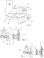
- FIG. 6 shows the corresponding representation during the opening movement by pivoting the cam in a counterclockwise direction.
- FIGS. 5 and 6 also indicate a damping device, which is formed by a damping member 52 and a cooperating with this sliding surface.
- the damping member is present in the present example on the cam, and the sliding surface is fixed to the housing, for example.
- the housing or formed or formed on a fixed element fixed to the housing but it could also be the other way round;
- the damping device requires two parts moving relative to one another during the opening and closing operation, between which friction may occur on a part of the shooting path and / or possibly also of the opening path.
- FIGS 7-9 show a detail of the brewing module with damping member 52 and sliding surface 51 in different stages.
- the damping member has an elastic element - here a damping ring 53, which extends around a guide portion 58 around - on.
- the damping ring is arranged in a receptacle 54 provided for this purpose and partially movable in this
- FIG. 7 shows the situation during the closing process, in which the cam plate 30 is moved in the direction of the direction of movement 60 to the housing (see. Fig. 5 ), and that is shortly before the final phase of the closing process, for example, when particularly high forces act on the second Brühhuntteil.
- the damping ring is loosely in the receptacle 54, without physical contact with a housing-fixed part: there is no damping.
- FIG. 8 the situation is shown, which is a short time later, ie towards the end of the closing process.
- the damping ring 53 abuts the sliding surface 51 and is pressed due to the forward movement (direction of movement 60) of the cam in a constriction 55, which results between receiving and sliding surface 51 and which is dimensioned so that the damping ring finds space only under deformation. Therefore, due to its elasticity, the damper ring presses against the sliding surface 51 and results in a frictional resistance counteracting the forward movement. In the illustrated embodiment, this frictional resistance decreases gradually during the further forward movement, since the sliding surface 51 is not quite parallel to the direction of movement but slightly bevelled, so formed fleeing.
- an optional inclined surface 56 together with the intrinsic elasticity of the damping ring and its engagement with the sliding surface 51, ensures that the damping ring is slidably engaged in Fig. 8 phase is pressed into this phase.
- damping element can be used, for example.
- An elastic lip Preferably, the damping element is arranged and formed so that, when it comes into contact with the sliding surface, by a movement relative to the sliding surface in the a direction is deformed and exerts an elastic, the deformation-counteracting force on the sliding surface, while it can escape when moving in the other direction and slide substantially force-free sliding surface.
- an elastic lip this is achieved in that the lip is not perpendicular to the sliding surface but at a non-right angle thereto.
- FIG. 10 An inventive machine for preparing a brewed beverage from a portion capsule 10, namely here a coffee machine, with a brewing module 1 is in FIG. 10 shown schematically. It has, in addition to the brewing module, a water tank 91, a pump 92 for supplying brewing water to the injector 4 and a water heating device 93 (for example, instantaneous water heater). Below the brewing module, a capsule container 95 is also arranged, in which the capsules 10 fall or are transported after the brewing process.
- the reference numeral 98 denotes a coffee cup.
Landscapes
- Engineering & Computer Science (AREA)
- Mechanical Engineering (AREA)
- Food Science & Technology (AREA)
- Apparatus For Making Beverages (AREA)
Priority Applications (13)
| Application Number | Priority Date | Filing Date | Title |
|---|---|---|---|
| EP17172058.4A EP3403546A1 (fr) | 2017-05-19 | 2017-05-19 | Module d'ébouillantage et machine de préparation de boissons |
| CN201880032522.6A CN110662467B (zh) | 2017-05-19 | 2018-05-16 | 冲泡模块和饮料制备机 |
| RU2019135702A RU2763234C2 (ru) | 2017-05-19 | 2018-05-16 | Заварочный модуль и машина для приготовления напитков |
| PL18726103.7T PL3624651T3 (pl) | 2017-05-19 | 2018-05-16 | Moduł do zaparzania i maszyna do przygotowywania napojów |
| EP18726103.7A EP3624651B1 (fr) | 2017-05-19 | 2018-05-16 | Module d'ébouillantage et machine de préparation de boissons |
| PT187261037T PT3624651T (pt) | 2017-05-19 | 2018-05-16 | Módulo de infusão e máquina de preparação de bebidas |
| CA3062587A CA3062587A1 (fr) | 2017-05-19 | 2018-05-16 | Module de brassage et machine de preparation de breuvages |
| KR1020197034710A KR20200033795A (ko) | 2017-05-19 | 2018-05-16 | 브루잉 모듈 및 음료 준비 머신 |
| PCT/EP2018/062650 WO2018210899A1 (fr) | 2017-05-19 | 2018-05-16 | Module d'infusion et machine de préparation de boisson |
| JP2019563896A JP2020520712A (ja) | 2017-05-19 | 2018-05-16 | 淹出モジュールおよび飲料調製機 |
| US16/613,585 US11337540B2 (en) | 2017-05-19 | 2018-05-16 | Brewing module and drinks preparation machine |
| AU2018269499A AU2018269499A1 (en) | 2017-05-19 | 2018-05-16 | Brewing module and beverage-preparing machine |
| HUE18726103A HUE060585T2 (hu) | 2017-05-19 | 2018-05-16 | Fõzõmodul és italkészítõ gép |
Applications Claiming Priority (1)
| Application Number | Priority Date | Filing Date | Title |
|---|---|---|---|
| EP17172058.4A EP3403546A1 (fr) | 2017-05-19 | 2017-05-19 | Module d'ébouillantage et machine de préparation de boissons |
Publications (1)
| Publication Number | Publication Date |
|---|---|
| EP3403546A1 true EP3403546A1 (fr) | 2018-11-21 |
Family
ID=58738984
Family Applications (2)
| Application Number | Title | Priority Date | Filing Date |
|---|---|---|---|
| EP17172058.4A Withdrawn EP3403546A1 (fr) | 2017-05-19 | 2017-05-19 | Module d'ébouillantage et machine de préparation de boissons |
| EP18726103.7A Active EP3624651B1 (fr) | 2017-05-19 | 2018-05-16 | Module d'ébouillantage et machine de préparation de boissons |
Family Applications After (1)
| Application Number | Title | Priority Date | Filing Date |
|---|---|---|---|
| EP18726103.7A Active EP3624651B1 (fr) | 2017-05-19 | 2018-05-16 | Module d'ébouillantage et machine de préparation de boissons |
Country Status (12)
| Country | Link |
|---|---|
| US (1) | US11337540B2 (fr) |
| EP (2) | EP3403546A1 (fr) |
| JP (1) | JP2020520712A (fr) |
| KR (1) | KR20200033795A (fr) |
| CN (1) | CN110662467B (fr) |
| AU (1) | AU2018269499A1 (fr) |
| CA (1) | CA3062587A1 (fr) |
| HU (1) | HUE060585T2 (fr) |
| PL (1) | PL3624651T3 (fr) |
| PT (1) | PT3624651T (fr) |
| RU (1) | RU2763234C2 (fr) |
| WO (1) | WO2018210899A1 (fr) |
Families Citing this family (2)
| Publication number | Priority date | Publication date | Assignee | Title |
|---|---|---|---|---|
| EP3687347B1 (fr) * | 2017-09-25 | 2023-07-26 | Société des Produits Nestlé S.A. | Distributeur de boissons doté d'un module amovible |
| US11636334B2 (en) | 2019-08-20 | 2023-04-25 | Micron Technology, Inc. | Machine learning with feature obfuscation |
Citations (8)
| Publication number | Priority date | Publication date | Assignee | Title |
|---|---|---|---|---|
| EP1859713A1 (fr) * | 2006-05-24 | 2007-11-28 | Nestec S.A. | Dispositif d'infusion pour capsule avec mécanisme de fermeture à rapport de transmission variable |
| WO2010118544A2 (fr) | 2009-04-15 | 2010-10-21 | Luna Technology Systems Lts Gmbh | Dispositif pour évacuer d'un conditionnement individuel un produit à extraire, dispositif de perforation et appareil d'extraction |
| EP2485629A2 (fr) | 2009-10-05 | 2012-08-15 | Nestec S.A. | Dispositif d'extraction de capsule ergonomique |
| US20150017288A1 (en) * | 2013-07-15 | 2015-01-15 | La Vit Technology Llc | Capsule based system for preparing and dispensing a beverage |
| US20150013279A1 (en) * | 2013-07-10 | 2015-01-15 | Keurig Green Mountain, Inc. | Beverage machine cartridge holder with damped movement |
| WO2015039258A1 (fr) | 2013-09-20 | 2015-03-26 | Luna Technology Systems Lts Gmbh | Dispositif de perforation pour appareils d'extraction pour la préparation de produits d'infusion |
| WO2015048914A1 (fr) | 2013-10-01 | 2015-04-09 | Luna Technology Systems Lts Gmbh | Module d'infusion |
| WO2016087190A1 (fr) | 2014-12-01 | 2016-06-09 | Qbo Coffee Gmbh | Module d'infusion, module de détection de capsule et machine de préparation de boisson |
Family Cites Families (11)
| Publication number | Priority date | Publication date | Assignee | Title |
|---|---|---|---|---|
| ATE495690T1 (de) * | 2006-05-24 | 2011-02-15 | Nestec Sa | Kapselperforationsmodul |
| CN200960050Y (zh) * | 2006-10-12 | 2007-10-17 | 广东亿龙电器股份有限公司 | 一种咖啡机的传动装置 |
| IT1395966B1 (it) * | 2009-08-03 | 2012-11-02 | Torino Politecnico | Macchina per la preparazione di bevande mediante infusione di un prodotto contenuto in una capsula o simile |
| CA2776298C (fr) * | 2009-10-05 | 2017-08-22 | Nestec S.A. | Dispositif d'extraction de cartouche |
| EP2505109A1 (fr) * | 2011-03-30 | 2012-10-03 | Celaya, Emparanza Y Galdos Internacional, S.A. | Machine à café avec chariot |
| CA2837427C (fr) * | 2011-06-09 | 2017-04-11 | Luigi Lavazza S.P.A. | Ensemble de distribution pour machines permettant de preparer des produits liquides au moyen de cartouches |
| US20150056343A1 (en) * | 2012-02-28 | 2015-02-26 | Nestec S.A. | Capsule-controlled motorized brewing unit |
| EP2948031B1 (fr) * | 2013-01-28 | 2020-02-26 | Tchibo GmbH | Module d'ébouillantage |
| CA2905217C (fr) * | 2013-04-03 | 2016-11-08 | 2266170 Ontario Inc. | Machine a dosettes et composants |
| PL2832270T3 (pl) * | 2013-07-31 | 2016-08-31 | Rheavendors Services Spa | Sposób i urządzenie do przyrządzania i dozowania kawy |
| WO2015136433A1 (fr) * | 2014-03-12 | 2015-09-17 | Sarong Societa' Per Azioni | Capsule pour boissons |
-
2017
- 2017-05-19 EP EP17172058.4A patent/EP3403546A1/fr not_active Withdrawn
-
2018
- 2018-05-16 HU HUE18726103A patent/HUE060585T2/hu unknown
- 2018-05-16 PL PL18726103.7T patent/PL3624651T3/pl unknown
- 2018-05-16 US US16/613,585 patent/US11337540B2/en active Active
- 2018-05-16 EP EP18726103.7A patent/EP3624651B1/fr active Active
- 2018-05-16 JP JP2019563896A patent/JP2020520712A/ja active Pending
- 2018-05-16 CN CN201880032522.6A patent/CN110662467B/zh not_active Expired - Fee Related
- 2018-05-16 AU AU2018269499A patent/AU2018269499A1/en not_active Abandoned
- 2018-05-16 CA CA3062587A patent/CA3062587A1/fr not_active Abandoned
- 2018-05-16 WO PCT/EP2018/062650 patent/WO2018210899A1/fr active Application Filing
- 2018-05-16 KR KR1020197034710A patent/KR20200033795A/ko active IP Right Grant
- 2018-05-16 PT PT187261037T patent/PT3624651T/pt unknown
- 2018-05-16 RU RU2019135702A patent/RU2763234C2/ru active
Patent Citations (9)
| Publication number | Priority date | Publication date | Assignee | Title |
|---|---|---|---|---|
| EP1859713A1 (fr) * | 2006-05-24 | 2007-11-28 | Nestec S.A. | Dispositif d'infusion pour capsule avec mécanisme de fermeture à rapport de transmission variable |
| WO2010118544A2 (fr) | 2009-04-15 | 2010-10-21 | Luna Technology Systems Lts Gmbh | Dispositif pour évacuer d'un conditionnement individuel un produit à extraire, dispositif de perforation et appareil d'extraction |
| EP2485629A2 (fr) | 2009-10-05 | 2012-08-15 | Nestec S.A. | Dispositif d'extraction de capsule ergonomique |
| EP2485629B1 (fr) * | 2009-10-05 | 2014-01-08 | Nestec S.A. | Dispositif d'extraction ergonomique pour une capsule |
| US20150013279A1 (en) * | 2013-07-10 | 2015-01-15 | Keurig Green Mountain, Inc. | Beverage machine cartridge holder with damped movement |
| US20150017288A1 (en) * | 2013-07-15 | 2015-01-15 | La Vit Technology Llc | Capsule based system for preparing and dispensing a beverage |
| WO2015039258A1 (fr) | 2013-09-20 | 2015-03-26 | Luna Technology Systems Lts Gmbh | Dispositif de perforation pour appareils d'extraction pour la préparation de produits d'infusion |
| WO2015048914A1 (fr) | 2013-10-01 | 2015-04-09 | Luna Technology Systems Lts Gmbh | Module d'infusion |
| WO2016087190A1 (fr) | 2014-12-01 | 2016-06-09 | Qbo Coffee Gmbh | Module d'infusion, module de détection de capsule et machine de préparation de boisson |
Also Published As
| Publication number | Publication date |
|---|---|
| RU2763234C2 (ru) | 2021-12-28 |
| RU2019135702A (ru) | 2021-06-21 |
| CN110662467B (zh) | 2021-12-21 |
| PL3624651T3 (pl) | 2023-01-16 |
| CA3062587A1 (fr) | 2019-11-06 |
| HUE060585T2 (hu) | 2023-04-28 |
| US20200060464A1 (en) | 2020-02-27 |
| AU2018269499A1 (en) | 2019-12-05 |
| EP3624651A1 (fr) | 2020-03-25 |
| WO2018210899A1 (fr) | 2018-11-22 |
| KR20200033795A (ko) | 2020-03-30 |
| CN110662467A (zh) | 2020-01-07 |
| PT3624651T (pt) | 2022-11-29 |
| JP2020520712A (ja) | 2020-07-16 |
| EP3624651B1 (fr) | 2022-08-24 |
| US11337540B2 (en) | 2022-05-24 |
| RU2019135702A3 (fr) | 2021-08-12 |
Similar Documents
| Publication | Publication Date | Title |
|---|---|---|
| EP2105074B1 (fr) | Dispositif et agencement de préparation d'un produit alimentaire ou de dégustation liquide et emballage en portion | |
| AT504054B1 (de) | Vorrichtung zur dämpfung bzw. abbremsung von beweglichen möbelteilen von möbelstücken | |
| EP3280300B1 (fr) | Machine de préparation de boissons | |
| EP2948031B1 (fr) | Module d'ébouillantage | |
| DE3400356C2 (fr) | ||
| EP3624651B1 (fr) | Module d'ébouillantage et machine de préparation de boissons | |
| CH710946A1 (de) | Brühvorrichtung mit zwei Brühkammern. | |
| EP2807963B1 (fr) | Machine à café expresso avec une unité d'infusion | |
| DE2930204A1 (de) | Selbstschliessendes ventil | |
| DE10334526B4 (de) | Kaffeebrühvorrichtung mit arretiertem Filterträger | |
| EP3624650B1 (fr) | Module d'ébouillantage et machine de préparation de boissons | |
| EP3373778B1 (fr) | Récipient collecteur pour la collecte de la matière insoluble utilisée lors de la préparation de boissons et dispositif d'infusion doté d'un tel récipient collecteur | |
| DE102010060291A1 (de) | Verschlussdeckel für einen Getränkebehälter | |
| EP3545801A1 (fr) | Machine à boisson avec système de drainage pour eau résiduelle | |
| DE60007022T2 (de) | Maschine zum Bereiten von Espressokaffee mit hydraulischer Vorrichtung zum Verdichten des Kaffeemehls | |
| WO2016079672A1 (fr) | Tête d'infusion pour machine à expresso | |
| DE60204837T2 (de) | Kaffeemaschine | |
| DE102015209991B4 (de) | Heißgetränkezubereitungsvorrichtung | |
| EP3017729A1 (fr) | Groupe de distribution pour un appareil de preparation de boissons | |
| DE3811675A1 (de) | Einrichtung zum verhindern des oeffnens eines unter druck befindlichen dampfdruckkochtopfes | |
| EP3120739B1 (fr) | Dispositif d'ebouillantage et dispositif de préparation de boissons chaudes | |
| EP3932269A1 (fr) | Unité de brassage destinée à la réduction de l'eau résiduelle pendant le processus de rinçage et procédé de fonctionnement d'une unité de brassage | |
| DE102009031757A1 (de) | Sicherheitsmechanismus und -verfahren für Getränkebereiter | |
| DE202017003230U1 (de) | Behältnisregal | |
| DE202015008228U1 (de) | Heißgetränkezubereitungsvorrichtung mit vereinfachter Betätigung |
Legal Events
| Date | Code | Title | Description |
|---|---|---|---|
| PUAI | Public reference made under article 153(3) epc to a published international application that has entered the european phase |
Free format text: ORIGINAL CODE: 0009012 |
|
| STAA | Information on the status of an ep patent application or granted ep patent |
Free format text: STATUS: THE APPLICATION HAS BEEN PUBLISHED |
|
| AK | Designated contracting states |
Kind code of ref document: A1 Designated state(s): AL AT BE BG CH CY CZ DE DK EE ES FI FR GB GR HR HU IE IS IT LI LT LU LV MC MK MT NL NO PL PT RO RS SE SI SK SM TR |
|
| AX | Request for extension of the european patent |
Extension state: BA ME |
|
| STAA | Information on the status of an ep patent application or granted ep patent |
Free format text: STATUS: THE APPLICATION IS DEEMED TO BE WITHDRAWN |
|
| 18D | Application deemed to be withdrawn |
Effective date: 20190522 |