EP3363350B1 - Morphologie de lumière et systèmes de collecte de données de mesure de résistance vasculaire, appareil et procédés - Google Patents
Morphologie de lumière et systèmes de collecte de données de mesure de résistance vasculaire, appareil et procédés Download PDFInfo
- Publication number
- EP3363350B1 EP3363350B1 EP17202843.3A EP17202843A EP3363350B1 EP 3363350 B1 EP3363350 B1 EP 3363350B1 EP 17202843 A EP17202843 A EP 17202843A EP 3363350 B1 EP3363350 B1 EP 3363350B1
- Authority
- EP
- European Patent Office
- Prior art keywords
- stent
- vrr
- resistance
- blood vessel
- segment
- Prior art date
- Legal status (The legal status is an assumption and is not a legal conclusion. Google has not performed a legal analysis and makes no representation as to the accuracy of the status listed.)
- Active
Links
- 238000000034 method Methods 0.000 title claims description 83
- 230000002792 vascular Effects 0.000 title claims description 44
- 238000005259 measurement Methods 0.000 title claims description 27
- 238000013480 data collection Methods 0.000 title description 4
- 238000012014 optical coherence tomography Methods 0.000 claims description 70
- 230000003902 lesion Effects 0.000 claims description 35
- 230000002966 stenotic effect Effects 0.000 claims description 29
- 239000000523 sample Substances 0.000 claims description 28
- 208000031481 Pathologic Constriction Diseases 0.000 claims description 26
- 230000017531 blood circulation Effects 0.000 claims description 23
- 208000037804 stenosis Diseases 0.000 claims description 23
- 230000036262 stenosis Effects 0.000 claims description 23
- 238000003384 imaging method Methods 0.000 claims description 21
- 210000004204 blood vessel Anatomy 0.000 claims description 14
- 238000004891 communication Methods 0.000 claims description 7
- 230000004044 response Effects 0.000 claims description 7
- 238000011282 treatment Methods 0.000 claims description 6
- 230000001419 dependent effect Effects 0.000 claims description 5
- 230000002093 peripheral effect Effects 0.000 claims description 3
- 210000001367 artery Anatomy 0.000 description 34
- 238000005457 optimization Methods 0.000 description 21
- 238000004364 calculation method Methods 0.000 description 17
- 238000005516 engineering process Methods 0.000 description 14
- 239000008280 blood Substances 0.000 description 13
- 210000004369 blood Anatomy 0.000 description 13
- 239000012530 fluid Substances 0.000 description 13
- 210000004351 coronary vessel Anatomy 0.000 description 12
- 210000001519 tissue Anatomy 0.000 description 12
- 230000008859 change Effects 0.000 description 11
- 230000003287 optical effect Effects 0.000 description 10
- 238000002608 intravascular ultrasound Methods 0.000 description 9
- 230000008901 benefit Effects 0.000 description 8
- 230000000544 hyperemic effect Effects 0.000 description 8
- 238000012545 processing Methods 0.000 description 8
- 238000004590 computer program Methods 0.000 description 7
- 238000010586 diagram Methods 0.000 description 7
- 230000000694 effects Effects 0.000 description 7
- 208000029078 coronary artery disease Diseases 0.000 description 6
- 230000006870 function Effects 0.000 description 6
- 238000002583 angiography Methods 0.000 description 5
- 238000009499 grossing Methods 0.000 description 5
- 238000004513 sizing Methods 0.000 description 5
- 230000003068 static effect Effects 0.000 description 5
- 238000003860 storage Methods 0.000 description 5
- 208000033990 Stent malfunction Diseases 0.000 description 4
- 238000013459 approach Methods 0.000 description 4
- 238000001727 in vivo Methods 0.000 description 4
- 210000004165 myocardium Anatomy 0.000 description 4
- 238000013146 percutaneous coronary intervention Methods 0.000 description 4
- 238000000926 separation method Methods 0.000 description 4
- 238000001514 detection method Methods 0.000 description 3
- 239000003814 drug Substances 0.000 description 3
- 229940079593 drug Drugs 0.000 description 3
- 230000002452 interceptive effect Effects 0.000 description 3
- 230000001788 irregular Effects 0.000 description 3
- 238000013138 pruning Methods 0.000 description 3
- 238000004088 simulation Methods 0.000 description 3
- 208000007536 Thrombosis Diseases 0.000 description 2
- 238000004458 analytical method Methods 0.000 description 2
- 238000003491 array Methods 0.000 description 2
- 230000004872 arterial blood pressure Effects 0.000 description 2
- 238000009530 blood pressure measurement Methods 0.000 description 2
- 238000011960 computer-aided design Methods 0.000 description 2
- 230000000875 corresponding effect Effects 0.000 description 2
- 238000009826 distribution Methods 0.000 description 2
- 238000011010 flushing procedure Methods 0.000 description 2
- 238000002513 implantation Methods 0.000 description 2
- 239000003550 marker Substances 0.000 description 2
- 230000006855 networking Effects 0.000 description 2
- 239000013307 optical fiber Substances 0.000 description 2
- 230000000250 revascularization Effects 0.000 description 2
- 239000004065 semiconductor Substances 0.000 description 2
- 230000007704 transition Effects 0.000 description 2
- 210000005166 vasculature Anatomy 0.000 description 2
- 230000024883 vasodilation Effects 0.000 description 2
- 238000012935 Averaging Methods 0.000 description 1
- OYPRJOBELJOOCE-UHFFFAOYSA-N Calcium Chemical compound [Ca] OYPRJOBELJOOCE-UHFFFAOYSA-N 0.000 description 1
- 201000000057 Coronary Stenosis Diseases 0.000 description 1
- 206010020565 Hyperaemia Diseases 0.000 description 1
- 244000208734 Pisonia aculeata Species 0.000 description 1
- 230000001133 acceleration Effects 0.000 description 1
- 210000003484 anatomy Anatomy 0.000 description 1
- 230000005540 biological transmission Effects 0.000 description 1
- 230000015572 biosynthetic process Effects 0.000 description 1
- 229910052791 calcium Inorganic materials 0.000 description 1
- 239000011575 calcium Substances 0.000 description 1
- 238000004422 calculation algorithm Methods 0.000 description 1
- 230000001427 coherent effect Effects 0.000 description 1
- 238000002586 coronary angiography Methods 0.000 description 1
- 238000012937 correction Methods 0.000 description 1
- 230000002596 correlated effect Effects 0.000 description 1
- 238000012888 cubic function Methods 0.000 description 1
- 230000007423 decrease Effects 0.000 description 1
- 238000003745 diagnosis Methods 0.000 description 1
- 201000010099 disease Diseases 0.000 description 1
- 208000037265 diseases, disorders, signs and symptoms Diseases 0.000 description 1
- 238000002224 dissection Methods 0.000 description 1
- 230000008030 elimination Effects 0.000 description 1
- 238000003379 elimination reaction Methods 0.000 description 1
- 238000002474 experimental method Methods 0.000 description 1
- 238000000605 extraction Methods 0.000 description 1
- 230000000004 hemodynamic effect Effects 0.000 description 1
- 239000007943 implant Substances 0.000 description 1
- 230000006872 improvement Effects 0.000 description 1
- 238000011065 in-situ storage Methods 0.000 description 1
- 238000005305 interferometry Methods 0.000 description 1
- 238000001990 intravenous administration Methods 0.000 description 1
- 230000000670 limiting effect Effects 0.000 description 1
- 230000002503 metabolic effect Effects 0.000 description 1
- 238000013508 migration Methods 0.000 description 1
- 230000005012 migration Effects 0.000 description 1
- 239000000203 mixture Substances 0.000 description 1
- 230000000877 morphologic effect Effects 0.000 description 1
- 230000004962 physiological condition Effects 0.000 description 1
- 230000002250 progressing effect Effects 0.000 description 1
- 238000004445 quantitative analysis Methods 0.000 description 1
- 230000009467 reduction Effects 0.000 description 1
- 230000002829 reductive effect Effects 0.000 description 1
- 238000009877 rendering Methods 0.000 description 1
- 230000000717 retained effect Effects 0.000 description 1
- 238000003325 tomography Methods 0.000 description 1
- 230000001131 transforming effect Effects 0.000 description 1
- 238000011144 upstream manufacturing Methods 0.000 description 1
- 230000006439 vascular pathology Effects 0.000 description 1
Images


Classifications
-
- A—HUMAN NECESSITIES
- A61—MEDICAL OR VETERINARY SCIENCE; HYGIENE
- A61B—DIAGNOSIS; SURGERY; IDENTIFICATION
- A61B5/00—Measuring for diagnostic purposes; Identification of persons
- A61B5/0059—Measuring for diagnostic purposes; Identification of persons using light, e.g. diagnosis by transillumination, diascopy, fluorescence
- A61B5/0062—Arrangements for scanning
- A61B5/0066—Optical coherence imaging
-
- A—HUMAN NECESSITIES
- A61—MEDICAL OR VETERINARY SCIENCE; HYGIENE
- A61B—DIAGNOSIS; SURGERY; IDENTIFICATION
- A61B5/00—Measuring for diagnostic purposes; Identification of persons
- A61B5/02—Detecting, measuring or recording pulse, heart rate, blood pressure or blood flow; Combined pulse/heart-rate/blood pressure determination; Evaluating a cardiovascular condition not otherwise provided for, e.g. using combinations of techniques provided for in this group with electrocardiography or electroauscultation; Heart catheters for measuring blood pressure
- A61B5/02007—Evaluating blood vessel condition, e.g. elasticity, compliance
-
- A—HUMAN NECESSITIES
- A61—MEDICAL OR VETERINARY SCIENCE; HYGIENE
- A61B—DIAGNOSIS; SURGERY; IDENTIFICATION
- A61B5/00—Measuring for diagnostic purposes; Identification of persons
- A61B5/68—Arrangements of detecting, measuring or recording means, e.g. sensors, in relation to patient
- A61B5/6846—Arrangements of detecting, measuring or recording means, e.g. sensors, in relation to patient specially adapted to be brought in contact with an internal body part, i.e. invasive
- A61B5/6847—Arrangements of detecting, measuring or recording means, e.g. sensors, in relation to patient specially adapted to be brought in contact with an internal body part, i.e. invasive mounted on an invasive device
- A61B5/6852—Catheters
-
- G—PHYSICS
- G06—COMPUTING; CALCULATING OR COUNTING
- G06T—IMAGE DATA PROCESSING OR GENERATION, IN GENERAL
- G06T7/00—Image analysis
- G06T7/0002—Inspection of images, e.g. flaw detection
- G06T7/0012—Biomedical image inspection
-
- A—HUMAN NECESSITIES
- A61—MEDICAL OR VETERINARY SCIENCE; HYGIENE
- A61B—DIAGNOSIS; SURGERY; IDENTIFICATION
- A61B34/00—Computer-aided surgery; Manipulators or robots specially adapted for use in surgery
- A61B34/10—Computer-aided planning, simulation or modelling of surgical operations
- A61B2034/101—Computer-aided simulation of surgical operations
- A61B2034/102—Modelling of surgical devices, implants or prosthesis
-
- A—HUMAN NECESSITIES
- A61—MEDICAL OR VETERINARY SCIENCE; HYGIENE
- A61F—FILTERS IMPLANTABLE INTO BLOOD VESSELS; PROSTHESES; DEVICES PROVIDING PATENCY TO, OR PREVENTING COLLAPSING OF, TUBULAR STRUCTURES OF THE BODY, e.g. STENTS; ORTHOPAEDIC, NURSING OR CONTRACEPTIVE DEVICES; FOMENTATION; TREATMENT OR PROTECTION OF EYES OR EARS; BANDAGES, DRESSINGS OR ABSORBENT PADS; FIRST-AID KITS
- A61F2/00—Filters implantable into blood vessels; Prostheses, i.e. artificial substitutes or replacements for parts of the body; Appliances for connecting them with the body; Devices providing patency to, or preventing collapsing of, tubular structures of the body, e.g. stents
- A61F2/82—Devices providing patency to, or preventing collapsing of, tubular structures of the body, e.g. stents
-
- G—PHYSICS
- G06—COMPUTING; CALCULATING OR COUNTING
- G06T—IMAGE DATA PROCESSING OR GENERATION, IN GENERAL
- G06T2200/00—Indexing scheme for image data processing or generation, in general
- G06T2200/24—Indexing scheme for image data processing or generation, in general involving graphical user interfaces [GUIs]
-
- G—PHYSICS
- G06—COMPUTING; CALCULATING OR COUNTING
- G06T—IMAGE DATA PROCESSING OR GENERATION, IN GENERAL
- G06T2207/00—Indexing scheme for image analysis or image enhancement
- G06T2207/10—Image acquisition modality
- G06T2207/10016—Video; Image sequence
-
- G—PHYSICS
- G06—COMPUTING; CALCULATING OR COUNTING
- G06T—IMAGE DATA PROCESSING OR GENERATION, IN GENERAL
- G06T2207/00—Indexing scheme for image analysis or image enhancement
- G06T2207/10—Image acquisition modality
- G06T2207/10072—Tomographic images
- G06T2207/10101—Optical tomography; Optical coherence tomography [OCT]
-
- G—PHYSICS
- G06—COMPUTING; CALCULATING OR COUNTING
- G06T—IMAGE DATA PROCESSING OR GENERATION, IN GENERAL
- G06T2207/00—Indexing scheme for image analysis or image enhancement
- G06T2207/30—Subject of image; Context of image processing
- G06T2207/30004—Biomedical image processing
- G06T2207/30101—Blood vessel; Artery; Vein; Vascular
Definitions
- This invention relates generally to the field of optical coherence tomographic imaging and more specifically to optical coherence techniques for diagnosing and treating vascular stenoses.
- Coronary artery disease is one of the leading causes of death worldwide. The ability to better diagnose, monitor, and treat coronary artery diseases can be of life saving importance.
- Intravascular optical coherence tomography is a catheter-based imaging modality that employs safe, non-ionizing near-infrared light to peer into coronary artery walls and present images valuable for the study of the vascular wall architecture. Utilizing broad-band coherent light, interferometry, and micro-optics, OCT can provide video-rate in-vivo tomography within a diseased vessel with resolution down to the micrometer level. This level of detail enables OCT to diagnose as well as monitor the progression of coronary artery disease.
- the quantitative assessment of vascular pathology and its progression involves the calculation of different quantitative measures such as the vessel cross-sectional area, mean diameter, and blood flow resistance, all of which rely on the accurate identification of the luminal border. While the luminal border in OCT images is clearly identifiable by the human eye, it is tedious, expensive, and time consuming to manually trace the luminal border. Thus there is a need for a reliable technique that can automatically identify the luminal border.
- OCT produces images that are higher in resolution and contrast compared to those of intravascular ultrasound (IVUS).
- IVUS intravascular ultrasound
- OCT images are typically acquired with blood cleared from the view of the optical probe. This is one reason the luminal border in OCT images is sharper and more defined compared to that in IVUS images.
- Cross-sectional diameter and area measurements provide interventional cardiologists with useful guidance for stent sizing and placement.
- the relationship of these geometric measurements to clinically relevant variables, such as ability of the artery to supply an adequate flow of blood to the myocardium when metabolic demands are high is not well understood.
- the percent stenosis of an individual coronary lesion measured by angiography was found to be a relatively poor predictor of the physiological significance of the lesion.
- CFR coronary flow reserve
- FFR fractional flow reserve
- the hemodynamic effects of a lesion depend on local variations of its cross-sectional area integrated over the entire length of a lesion. Therefore, the minimum cross sectional area alone is insufficient to characterize the pressure drop across a lesion at a given flow rate, especially in patients with diffuse coronary disease.
- the flow resistance or pressure drop caused by an incremental segment of a lesion depends on its shape as well as its cross-sectional area and length.
- the eccentricity and local slope of the walls of the artery can influence the effective resistance of a lesion, because losses due to flow separation and turbulence depend on local flow velocity.
- the flow reserve of the myocardium supplied by the vessel can be low, due to microvascular disease, flow through collateral branches, or capillary shunts within infarcted myocardium. Therefore, even if the vascular resistance of a lesion in the vessel is high, revascularization may be contraindicated, because the pressure drop across the lesion may be clinically insignificant.
- Intravascular OCT imaging applied in combination with new clinical parameters based on advanced analysis of lesion morphology, has the potential to overcome many of the limitations of conventional measures of lesion severity based on angiography and IVUS.
- the high resolution of OCT enables accurate measurement of the shape and dimensions of the vessel lumen over the length of the lesion and its adjacent reference segments.
- advanced models of flow dynamics enable the physiological significance of lesions to be estimated under both normal and hyperemic conditions. It should be realized, however, that the clinical value of quantitative lesion morphology measurements-even when accurate-may be limited by physiological conditions in certain patients.
- high-frequency OCT imaging has the advantage that it can precisely delineate three-dimensional contours of long segments of coronary arteries in a few seconds to assist cardiologists in their real-time diagnosis and treatment during PCI procedures.
- US Patent Publication No. US 2007/135707 describes a computerized workflow method for stent planning and stenting procedure.
- US Patent Publication No. US 2006/135870 describes methods and apparatuses for positioning within an internal channel.
- Sihan K et al entitled "A novel approach to quantitative analysis of intravascular optical coherence tomography imaging" computers in cardiology, 2008, IEEE, Piscataway, NJ, USA, 14 September 2008 , discloses a method for automatic contour tracing of vascular images based on 2d images.
- MLA minimum lumen area
- the present invention addresses these needs.
- the invention relates to an automated computer-based method of evaluating a region of a lumen, as set out in the appended claims.
- the method comprises the steps of collecting a set of data regarding a vessel segment of length L using an optical coherence tomography system, the set comprising a plurality of cross sectional areas at a plurality of positions along the length; determining a vascular resistance ratio (VRR) using a processor from at least a portion of the set of data; and determining a characteristic of at least a portion of the region disposed along the length L in relation to the vascular resistance ratio.
- VRR vascular resistance ratio
- the method is applied to the region that contains a stenotic lesion.
- the method further comprises the step of displaying at least one numerical or graphical measure of stent length used to treat the stenotic lesion.
- the step of determining the vascular resistance ratio is performed using a lumped resistor model.
- the invention in another aspect, relates to a method for automatically identifying the luminal border in an in -situ OCT vascular image.
- the method includes comprises the steps of generating a mask of the OCT lumen image using a computer; defining a plurality of scan lines in the mask; identifying a region as tissue on each scan line; defining contour segments in response to the plurality of scan lines and the region of tissue on each scan line; identifying valid neighboring contour segments; interpolating missing contour data between valid neighboring contour segments; assessing the likely correctness of the computed contour and indicating to the user on which image frames the computed contour may require manual adjustment.
- the method includes the step of detecting and removing guide wire and similar artifacts.
- the identification of a tissue region includes the steps of finding a plurality of start/stop pairs on each scan line; calculating thickness and gap of each said start/stop pair; calculating a weight based on said thickness and said gap; and defining the tissue region based on the largest weight of tissue and gap.
- the step of defining connected contour includes finding the scan line with the largest weight; searching for discontinuities in both directions from the scan line to define a valid segment; and identifying the root of the contour as the longest of the valid segments.
- the step of identifying valid neighboring contour includes finding the nearest clockwise and counter-clockwise neighbors of each of the contour segments that pass angular, radial, and Euclidean distance thresholds.
- the step of detection and removal of guide wire shadow artifact comprises the steps of clearing an image binary mask by fitting an ellipse to the foreground data of the mask and blanking the area inside ellipse; building an intensity profile using the cleared mask; identifying the guide wire shadow region in the intensity profile; detecting a guide wire offset within the shadow region; collecting the midpoint of detected guide wires on all frames; building a minimum spanning tree using the collected midpoints; and pruning the resulting minimum spanning tree to remove outliers resulting from non-guide wire shadows.
- the step of interpolating missing data includes the steps of identifying required interpolation control points with valid contour data on both ends of the missing contour segment; and using the control points to interpolate the missing contour segment.
- the steps are performed on all missing contour segments that need to be interpolated.
- the step of searching for discontinuities comprises the steps of calculating a scan line-to-scan line offset change histogram; smoothing said histogram; identifying the smallest change with zero count from the histogram; and using the smallest change as a continuity measure.
- the step of evaluating the correctness of the computed contour comprises the steps of computing an "Error Measure” by fitting an ellipse to the computed contour; computing the root mean square error between the computed contour and the fitted ellipse; normalizing the root mean square error to the average diameter of the ellipse; and multiplying the normalized root mean square error by the ratio of the number of scan lines where the lumen was successfully detected to the total number of scan lines in the image frame.
- the resulting Error Measure parameter is compared to a threshold and, for image frames where the threshold is exceeded, the user is notified that manual contour correction may be required.
- the notification can take the form of "alert frames" drawn on a longitudinal display of the images of the pullback region.
- the invention in another aspect, relates to an automated method for quantifying a vascular resistance including the steps of selecting proximal and distal frames of an OCT image; calculating actual vascular resistance of the vascular segment enclosed by said proximal and the distal frames; calculating a total vascular resistance of the vascular segment; and calculating vascular resistance ratio using the actual vascular resistance and said total vascular resistance.
- the step of calculating actual vascular resistance comprises the steps of extracting luminal contours of all frames enclosed by the proximal and the distal frames inclusive; calculating cross-sectional areas from the extracted contours; constructing a smooth area graph; and using the smooth area graph in the actual vascular resistance calculation.
- the step of calculating the total vascular resistance comprises the steps of: fitting a shape between said proximal and said distal frames; and calculating cross-sectional areas of the shape at all frame positions enclosed by the proximal and the distal frames inclusive.
- the step of constructing a smooth area graph includes the steps of constructing a graph using the cross-sectional areas; interpolating missing area values on the graph; and smoothing the resulting graph.
- vascular resistance is calculated by computational fluid dynamics from the detected three-dimensional luminal border between the proximal and distal planes.
- Another aspect is a method of placing a stent including the steps of: (a) measuring the parameters in the region of interest in an OCT image of a vessel; (b) simulating the placement of the stent in the region of interest; (c) recalculating the parameters in the region of interest; and repeating Steps b and c until the desired result is obtained.
- FIG. 1a is a high level schematic diagram depicting components of an OCT system 10 constructed in accordance with the invention.
- Figure 1a is highly generalized and not to scale.
- a vessel of interest 20 defining a lumen having a wall 21 is imaged using catheter 25 having a catheter portion having an optical fiber-based imaging probe 30 disposed therein.
- the catheter 25 includes a flushing subsystem having flush ports 32.
- the flushing system can be of any suitable type or variety that displaces a sufficient amount of blood such that in vivo OCT data collection can proceed using the probe 30.
- the system 10 includes an OCT system or subsystem 36 that connects to the imaging probe 30 via an optical fiber.
- the OCT system or subsystem 36 can include a light source such as a laser, an interferometer, various optical paths, a clock generator, photodiodes, and other OCT system components.
- a computer or processor is part of the OCT system 36 or is included as a separate subsystem 40 in electrical communication with the OCT system 36.
- the computer or processor 40 includes memory, storage, buses and other components suitable for processing data. for lumen detection and pull back data collection as discussed below.
- the computer or processor includes software implementations or programs 41 of the methods described herein that are stored in memory and executed using a processor.
- a display 42 is part of the overall system 10 for showing cross-sectional scan data as longitudinal scans or in other suitable formats.
- a method and apparatus of automatically locating a lumen boundary at a position in a vessel of interest using an OCT image or the underlying data) and from that measuring the diameter of the vessel is described. From the diameter of the vessel and calculated blood flow rate a number of clinically significant physiological parameters are then determined and various images of interest generated. One use of these images and parameters is to aid the clinician in the placement of a stent.
- the system uses these measurements to allow the clinician to simulate the placement of a stent and determine the effect of the placement.
- various patient treatments are then performed.
- the system determines the lumen boundary.
- data taken by an OCT system is used with the methods described herein to recognize and avoid residual blood, guide wire reflections, and other structures that may appear to be part of the vessel wall. Interpolation of a continuous boundary is accomplished by imposing continuity of the inner surface of the vessel across neighboring frames.
- Figs. 1 and 2 show examples of lumen contours drawn automatically by the software based method on two frames of a frequency domain OCT (FD-OCT) image sequence.
- FD-OCT frequency domain OCT
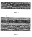
- the software shows the cross-sectional areas calculated automatically for all frames in a sequence as a graph superimposed on the longitudinal (L)-mode image ( Fig. 3 ).
- the lines 10, 10' indicate the position of the user-selected proximal and distal reference frames.
- An alternative embodiment of the display shows the mean diameter values profile in a separate panel above the L-mode display ( Fig. 3).
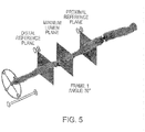
- Fig. 4 shows an alternative display in which the mean cross-sectional diameters and an "Alert Frame" feedback are shown in a separate panel above the OCT L-mode.
- the alert frame, labeled AF indicates a frame where the system believes human intervention is required to verify the values shown.
- the mean diameter of each cross-section is calculated either as the diameter of a circle with an area equal to that of the cross section or as the mean of the chord lengths at all angles drawn through the centroid of the lumen cross-section.
- the minimum lumen area (MLA), proximal and distal reference areas, percent diameter stenosis, and the length between references are displayed numerically in the same panel.
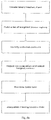
- the system then also generates a three-dimensional rendering of the shape of the vessel lumen as calculated from the cross-sectional measurements.
- An example is shown in Fig. 5 .
- the user sets the positions of the proximal and distal reference planes manually on the 3D image by dragging either line marker in the L-mode display or reference planes on the 3D display.
- the longitudinal position between the reference markers at which the cross-sectional area is smallest is found automatically and a separate marker plane is placed automatically by the computer at this position.
- the entire display can be rotated around the longitudinal axis by steering a compass wheel in the display.
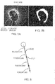
- the method of detecting the lumen of a vessel in an OCT image is briefly described.
- the image mask is a binary image mask to demark the general contour of the lumen wall.
- a list of weighted tissue regions is created and potential contours defined. Discontinuities in these contours are rejected and the longest remaining contour selected. Any artifacts such as the shadow of the guidewire are removed and missing contour data is interpolated to correct for missing portions of the image.
- the smallest data unit in an OCT image is called a sample.
- a sequence of samples along a ray 20 originating at the catheter center to the maximum imaging depth is called a scan line.
- An OCT image is typically acquired one scan line at a time.
- a cross-sectional image is formed by a collection of scan lines as the OCT catheter rotates. Further, to image a segment of the vessel, the catheter is moved longitudinally along the vessel while rotating, hence acquiring a set of cross-sectional images in a spiral pattern. It should be noted that while the present invention is described in the context of OCT images, the present invention is not so limited. Thus, for example, identifying any border, boundary, or contour in any vascular image is within the spirit and scope of the present invention.
- a cross-sectional image of the vessel is created for each complete rotation of the optical probe.
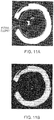
- These images are individually preprocessed and a suitable threshold is applied to create a binary foreground / background image mask, wherein the foreground is defined to contain the potentially relevant image information (e.g. the vessel wall) and the background represents the empty luminal space between the catheter and vessel wall, as well the 'noise floor' beyond the deepest imaging depth within the wall.
- the image mask is further processed by convolving the image mask with a median filter that has a suitable width W and a suitable height H. This operation fills in the gaps and removes the noise as each of the image mask values is replaced by the median value in its WxH neighborhood window.
- An example of a resulting mask is shown in Fig. 7b .
- the resulting mask has the same dimensions as the original cross-sectional image.
- each scan line of the mask is processed to find all pairs of start and stop samples as shown in Fig. 6b .
- the start sample denotes the start of a tissue (foreground) region while the stop sample represents the end of a tissue region.
- the thickness of a tissue region is calculated as the number of samples between a start sample and a stop sample (i.e. the number of samples identified as foreground).
- a gap region is calculated as the number of samples between a stop sample and a start sample (i.e. the number of samples identified as background).
- any one scan line it is possible to have more than one region identified as tissue, as shown in Fig. 8 .
- This is mainly due to (but not limited to) blood artifacts, if the lumen is not completely cleared of flowing blood during the image acquisition.
- a weight is associated with each detected region.
- every scan line in a given cross-sectional image should have, at most, one sample that will be on the lumen contour.
- the calculated weight associated with the sample on any given scan line is kept for further utilization.
- a contour segment can be defined, in one embodiment, as a group of contiguous scan lines with no discontinuities.
- a discontinuity is a scan line-to-scan line change in the sample number (offset) that exceeds a predetermined continuity threshold.
- the method begins by searching for the line with the largest weight among the lines not yet grouped in segments (initially, these are all scan lines in a given cross-sectional image).
- a segment is identified by searching for discontinuities clockwise and counter-clockwise from the line with the largest weight as illustrated in Fig. 9 .
- One way to determine a discontinuity threshold is to compute and smooth a line-to-line change in an offset histogram.
- Fig. 10 shows an illustration of a possible smoothed histogram.
- the cost represents the line-to-line change of offset, and the count represents the frequency (the number of occurrences) for a given change of offset.
- Such a histogram typically has a bi-modal distribution.
- the peaks with the lower costs represent acceptable, physiologically feasible changes in offsets, while the peaks with the higher costs represent transitions to and from artifacts.
- a region of zero count separates the two peaks of the bi-modal histogram.
- the smallest cost with zero count is identified and used as a threshold. It should be noted that this invention is not limited to this one particular method for determining the discontinuity threshold.
- the luminal contour is a possible grouping of one or more contour segments.
- the root (first segment to add to the contour) of the contour is selected as the longest valid segment.
- the nearest clockwise and counter-clockwise neighboring segments of each potential contour segment are identified. Valid neighbors must pass an angular distance threshold, a radial distance threshold, and a Euclidian (direct connection) distance threshold.
- Each potential contour is then traversed clockwise and counter-clockwise and the longest contour is selected.
- an ellipse is fitted to the foreground of a median mask (shown in Fig. 11a ). The area inside of the ellipse is then blanked to remove any small disconnected regions as shown in Fig. 11b . Applying the resulting mask to the OCT image, the average intensity value along each scan line of the masked OCT image is calculated (shown in Fig. 11c as a plurality of scan lines of varying shading). The guide wire shadow is then identified via the use of a suitable gradient filter, such as the Sobel edge detector and the guide wire offset (its radial distance from the catheter) is detected inside the guide wire shadow region.
- a suitable gradient filter such as the Sobel edge detector and the guide wire offset (its radial distance from the catheter) is detected inside the guide wire shadow region.
- Shadows from other sources such as stent struts and residual blood are also detected and need to be delineated from the guide wire shadow.
- the midpoints of all detected shadow regions on all frames is then collected and used as nodes to build a minimum spanning tree.
- the nodes of the tree are selected and connected such that: no points on the same frame are connected together; and any given node is connected to a parent node that minimizes a weight value.
- the weight value is calculated as the sum of the distance and slope difference between a node and its parent node.
- a sample resulting tree is shown on the L-mode display in Fig. 11d .
- the tree is pruned by removing small branches (according to a suitable threshold) as shown in Fig. 11e .
- Missing contour data is interpolated as shown in Figs. 1 and 2 .
- a smooth curve between two points is interpolated using the cosine function.
- the range of values of a cosine function is +1 to -1 inclusive in the domain 0 to ⁇ . Since the interpolation between two points requires a weighting range from 0 to 1 inclusive, it is desirable to adjust the cosine range.
- Using the function (1-cos) provides a range from 0 to 2 inclusive and dividing by 2 yields (1-cos)/2 with the required range from 0 to 1.
- any suitable function such as the cubic function or the Hermite function to interpolate missing data using four or more control points instead of two.
- the general relation is given by (1- ⁇ )y 1 + ( ⁇ )y 2 , where ⁇ is the interpolation weight ranging from 0 at x 1 to 1 at x 1 + ⁇ x.
- an area graph vs. longitudinal position is constructed from the individually calculated cross-sectional areas as shown in Fig. 12 .
- a suitable interpolation method can be used for any missing data (where the contour extraction might have failed for any reason).
- the resulting graph ( Fig. 3 ) is smoothed to remove sharp transitions in the area graph.
- One way to smooth the area graph is to use a median filter. It should be noted that this invention is not limited by any one particular smoothing method.
- the vascular resistance ratio quantifies the blood flow resistance of a stenotic vessel segment relative to the flow resistance of the entire vessel branch, assuming maximum vasodilation of the peripheral coronary vasculature.
- the VRR is defined as: VRR ⁇ R s R T where R s is the blood flow resistance of the stenotic segment and R T is the total flow resistance of the branch vessel in which the stenotic region is located. VRR ranges from 0 (no vessel narrowing) to 1 (all flow resistance due to the stenosis).
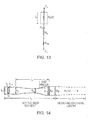
- the calculation of VRR is based on a lumped parameter model ( Fig. 13 ) of the blood flow through a stenosed branch of a coronary artery under hyperemic conditions.
- the blood flow Q driven by the difference between the arterial blood pressure P a and the coronary venous pressure P v , is limited by the total flow resistance ( R T ) of the branch of the vessel through which the blood is flowing.
- R mv P a ⁇ P v Q max
- Q max is the maximum blood flow that can be achieved in the branch when the pressure drop across the epicardial arteries is negligible (i.e., R s + R e ⁇ 0).
- the quantity in braces which has units of mm Hg cm -1 s, is the hyperemic microvascular resistance index, designated as h-MRv.
- h-MRv hyperemic microvascular resistance index
- An important advantage of determining hyperemic resistance using velocity instead of flow is that velocity normalizes flow for differences in arterial diameter due to branching and is preserved between proximal and distal segments.
- Table 1 lists published values of h-MRv measured during PCI with a Doppler flow wire. The values lie within a relatively narrow range for both treated and untreated vessels.
- h-MRv is a constant approximately equal to 1.0 mm Hg cm -1 s, a value that lies at the lower end of the distribution of resistances in Table 1 for upsized stented arteries.
- the value of A n in Eq. 5 is assumed to equal the cross-sectional area of the proximal segment of the reference vessel.
- R e the epicardial resistance outside of the stenotic segment of the vessel
- R s the epicardial resistance outside of the stenotic segment of the vessel
- the cross-sectional lumen areas A i are measured in the frames of the OCT image located outside of the stenotic region, so that the total number of available frames M depends on the lengths of the proximal and distal reference segments in the image.
- L T 8 cm for the main coronary arteries (LAD, LCX, and RCA), so that L e can be found directly by subtracting the length of the OCT image region from L T .
- a better estimate of the epicardial length can be obrained from lengths measured by angiography, if such data is available.
- the mean area is estimated as the average of the diameters of the proximal and distal reference segments.
- R s Calculation of the stenotic resistance, in Eqn. 3 is complicated by its dependence on blood flow.
- R s is composed of a flow-independent component that results from viscous losses and a flow-dependent component that results from kinetic losses.
- a variety of methods have been developed for calculation of the flow resistance of stenotic lesions. Three different embodiments of methods (one analytical and two numerical) by which R s can be calculated based on measurements of lumen morphology by OCT will now be discussed.
- the first embodiment of a method for calculation of R s is adapted from a model of pressure loss in stenotic lesions developed by Kirkeeide.
- Fig. 14 illustrates the cylindrically symmetrical geometry on which the model is based.
- R v 8 ⁇ C 2 d p A m 2
- d p is the diameter of the artery on the proximal side of the stenosis
- a m is the minimum lumen area of the stenosis
- C 2 0.45.
- the flow-dependent component of R s in Eq. 9 includes losses due to flow separation and recirculation at the exit of narrowed regions of the artery.
- the effective resistance of a blood vessel can significantly exceed that predicted by Poiseuille's law, which is based on analysis of laminar flow of a Newtonian fluid through a straight cylinder.
- k e C 3 ⁇ 2 1 A m ⁇ 1 A d 2
- ⁇ is the mass density of the blood
- a d is the area of the artery distal to the stenosis
- C 3 1.21 + 0.08 l s d d
- l s is the length of the stenosis, defined as the region between the wall angle inflection points on either side of the stenosis ( Fig. 14 ), and d d is the diameter of the artery on the distal side of the stenosis. This equation accounts for the increase in expansion losses with lesion length.
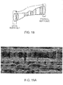
- the other embodiments of the method instead of Kirkeedee's equations, use a numerical Navier-Stokes solver such as Flo Works, (SolidWorks Corporation, Concord, MA) or Fluent (Ansys, Ann Arbor, MI) or equivalent to calculate the stenotic resistance R s in the model in Fig. 13 .
- the vessel contours are delineated by OCT and the flow within the walls is broken into thousands of small volumes. Simultaneously, at each volume, the Navier-Stokes momentum and conservation of mass equations are solved to compute the flow field through the volume. From this flow field the pressure drop along the vessel is found.
- the cylindrically symmetrical computational flow model the same area-versus- position graphs are used as in the first embodiment.
- the Navier-Stokes equations are solved assuming the shape is a perfect circle at each location along the OCT image.
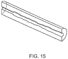
- the full-3D computational flow model based on the actual OCT lumen contours is used.
- the wall geometry is broken into triangles spanning every other frame and every 15° around the catheter. Figs 15 and 16 show sections of the geometry on which blood flow is modeled.
- the parent vessel area is taken as the proximal area at the reference plane.
- One daughter vessel is taken as the distal reference plane.
- the initial guess of the remaining daughter vessel areas is taken from an algorithm that interrogates the OCT image.
- the radius of the vessels is calculated, assuming they are circular. These radii are all multiplied by a single scale factor.
- the scale factor is determined by Murray's law. Murray's law is applied one branch at a time. The area remaining after the most proximal branch area is subtracted is used as the parent area for the next branch. The remaining area after Murray's law is applied to the last branch will equal the distal reference area.
- R s (Q) is calculated numerically with the computational flow simulation program with R e and R mv calculated in the same way as in the first embodiment of the method.
- R e and R mv are both independent of flow (i.e., produce a pressure drop linear with flow). They are simply added as a single resistor to the numerical simulation.
- the numerical flow simulator automatically adjusts the flow to maintain P v -P a .
- the reference area, A n in Eqn. 5, is calculated differently for the two models.
- the cylindrically symmetric model (second method) does not have any branches, therefore A n is calculated based on the average of proximal and distal areas.
- the velocity in the Flo Works geometry will be an average of the flows that would be encountered through the tapering section.
- the full 3-D model (third embodiment) includes branches, therefore A n is calculated based on the proximal area only.
- the lumped resistor method shown in Fig. 13 is extended for the full 3-D Computational Flow Model in Figure 24 .
- the resistance of the branches R 1 , R 2 .... R N and R Distal are each composed of the series resistors R e + R mv .
- the downstream end of the every branch resistor is at P v (10 mm Hg).
- the upstream end of the resistor is at the static pressure that numerical method calculates at that branch.
- the input pressure of the parent artery at the proximal reference is 90 mm Hg.
- R e of each branch is calculated based on the location in the image. Calculation of R mv is more complex. According to Murray's law, the sum of the cross-sectional areas of branches coming off a parent is greater than the cross sectional area of the parent. Consequently, the velocity decreases after every branch. This affects R mv for the entire artery and for each branch.
- R mv for the entire artery is adjusted by assuming the 1.0 mm Hg cm -1 s value of h-MRv was determined based on a reference diameter of 3.4 mm.
- R mv is adjusted downwards according to the ratio of the proximal reference diameter to the reference diameter to the 1 ⁇ 4 power.
- the 1 ⁇ 4 power equates pressure drops through the vasculature. Data on the variation of velocity data through the coronaries is limited, but the 1 ⁇ 4 power rule seems to correlate the published data as shown in Table 3.
- a more sophisticated approach would adjust R mv according to the vessel type (LAD: left anterior descending artery, RCA: right coronary artery, LCx: left circumflex).
- R mv for each branch is adjusted by the same 1 ⁇ 4 power of the diameter ratio of the branches to the reference diameter of 3.4 mm. If a branch is smaller than 2 mm, R mv is taken at 2 mm diameter. R mv for all the daughter branches is summed to insure it adds up to R mv for the proximal reference. If it is different, R mv for all the branches are scaled equally.
- the pressure and flow are obtained along the artery length.
- the slope of the total pressure along the length can be used to highlight areas of high resistance.
- the static pressure along the length can be correlated with pressure measurements.
- VRR is calculated between any two points of interest, usually the distal and proximal references. Since the flow is calculated, other indices that use flow and pressure, such as Stenotic Reserve Index (SRI) can be calculated.
- SRI Stenosis Resistance Index
- SRI Pressure Difference Between Measurement Points dP / Proximal Velocity
- SRI is calculated by assuming a velocity.
- Velocity is fairly constant in human arteries. In one study of 32 patients after percutaneous coronary intervention PCI, the measured velocity was 79 ⁇ 17.2 cm/s. Since the velocity variation is small and the SRI curve is fairly independent of velocity, the estimate of SRI made without velocity measurements can be acceptable.
- Velocity is a better way to normalize SRI than flow because pressure drop is mostly proportional to velocity. If flow is used, it typically underestimates the effect of a stenosis in a large vessel and conversely overestimates the effect of a stenosis in a small vessel.
- the velocity that is selected is the velocity at a reference diameter, not the stenosis velocity.
- the physician selects the proximal reference and the velocity measurement is taken there. The resulting SRI will give the physician the resistance that will be eliminated by the stent.
- the flow through the region of interest will change if a side branch is detected.
- the flow down the side branch will be estimated from the side branch size and the reduction in area from the proximal to distal reference. Both the algerbraic equations and the Navier-Stokes Equation are modified to include the side branches.
- LSRI Total Pressure Difference / Velocity ⁇ Integrated Poiseuille Equation
- total pressure difference is the static pressure at a first location plus the velocity head ( ⁇ V 1 2 /2) at the first location minus the static pressure at a second location plus the velocity head ( ⁇ V 2 2 /2) at the second location.
- Velocity, V is the bulk average velocity.
- the integrated Poiseuille equation is the laminar flow pressure drop calculated between the reference locations assuming the diameter increases linearly. This is an improvement over the standard SRI measurement because the total pressure is more reflective of the true losses in an artery than the static pressure used in standard SRI and the integrated Poiseuille equation removes the effects of the distance between measurement locations, which is a limitation of standard SRI.
- FFR fractional flow reserve
- VRR vascular resistance ratio
- an FFR value greater than or equal to 0.75 typically is considered to mean that treatment is not required.
- the FFR is measured following the administration of drugs that cause a maximum hyperemic response by causing the capillary beds to dilate followed by the taking of an intravenous pressure measurement.
- a VRR of less than 0.25 means that treatment is not indicated.
- a benefit of VRR is that, as shown below, a VRR calculation may be made without the use of drugs or the measurement of intravascular pressure.
- Fig. 17 One concept for displaying this information is illustrated in Fig. 17 .
- the segment of the artery centered on the MLA plane that encompasses a user-selectable fraction ⁇ (typically 0.9 ⁇ ⁇ ⁇ 0. 95) of the total vascular resistance is highlighted.
- the length of the highlighted region, 2 ⁇ L , centered on the MLA position l 0 is determined such that the relationship ⁇ N l 0 + ⁇ L N l 0 + ⁇ L R i ⁇ ⁇ R m is satisfied.
- N (l 0 - ⁇ L ) and N (l 0 + ⁇ L ) are the frame numbers at the distal and proximal limits of the vessel segment.
- the high-resistance regions can be identified independently of the location of the MLA cross section by sorting the resistances of the incremental segments from highest to lowest and highlighting only those segments at the top of the list that sum to a user-selectable fraction of the total vascular resistance.
- the advantage of this method is that more than one region of high resistance in a diffusely narrowed artery can be identified readily, as shown by the example in Fig. 18 .
- the present invention also provides methods for optimizing stent choice and placement automatically or semi-automatically via interactive commands. These flow calculations, when combined with a set of a priori constraints, enable a cardiologist to optimize the length, diameter, and longitudinal position of a stent before implantation.
- a three-dimensional (3D) image of the lumen of a coronary artery derived from OCT image data is depicted.
- the morphological data represented by the three-dimensional image of the lumen provide the starting point for various embodiments of the stent optimization procedure.
- the first image-processing step reduces the 3D data set to a cylindrically symmetrical data set that shows the mean diameter of each cross section along the axis of the catheter.
- the mean diameter can be found by averaging the lengths of chords drawn through the centroid of the lumen cross section.
- Figs. 19a and 19b show examples of displays of mean-diameter for an OCT image of a coronary artery.
- the branches of the artery are shown as perpendicular bars with widths equal to the widths of the ostia of the branches
- the vessel branches are shown as circles with diameters to the widths of the ostia of the branches.
- the mean-diameter display shows the position of a reconfigurable stent superimposed on the vessel profile, as illustrated in Fig. 20 .
- the expanded diameter, length, and longitudinal position of the stent are the main variables that determine the effectiveness of the stent in restoring the available blood flow to the heart muscle.
- the present invention employs the difference between the calculated values of the vascular resistance ratio ( VRR ) before and after stenting as a key stent optimization parameter.
- Another important optimization parameter is the maximum stent malapposition distance, defined as the widest separation between the surface of the stent struts and the vessel wall over the entire length of the stent.
- Minimization of this distance, especially for drug-eluting stents, is necessary to assure that the stent is affixed firmly to the vessel wall and that that the stent provides adequate radial support to prevent collapse of the vessel.
- a third important optimization parameter is the degree of overlap of the stent and the ostia of side branches. Minimal overlap is desirable to avoid blockage of blood flow to branches as a result of thrombus formation or growth of new tissue on the stent struts.
- the various embodiments of the present invention provide methods for choosing the optimal stent length, diameter, and longitudinal position in accordance with the aforementioned optimization parameters ( VRR , malapposition distance, branch overlap, presence of calcium, etc.).
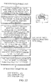
- the flow chart in Fig. 21 outlines the optimization procedure associated with one specific embodiment.
- the user chooses a desired stent length, L fixed , and the optimization proceeds iteratively to find the longitudinal position of the stent, x opt , and diameter of the stent, D opt , that minimizes VRR while maintaining a malapposition distance, ⁇ , less than a maximum allowable distance, ⁇ max , and a stent diameter less than D max .
- ⁇ max is fixed at a small value between 0 and a value deemed clinically insignificant (e.g., 0.1 mm) and D max is set equal to the maximum diameter of the vessel measured within the imaged segment plus one stent diameter increment (typically 0.25 mm).
- the sets of available stent diameters ⁇ D min ⁇ D ⁇ D max ⁇ and stent positions ⁇ 0 ⁇ x ⁇ ( L - L fixed ) ⁇ are limited to discrete values separated by clinically significant increments. Further acceleration of the optimization can be achieved by employing a multivariate look-up table of stent diameters and stent positions instead of linear arrays of variables.
- additional constraints such as the degree of overlap with side branches and calcified regions, are included within the scope of the invention.
- this specific embodiment of the optimization procedure In addition to reporting the recommended diameter and position of the stent to the user, this specific embodiment of the optimization procedure also reports the predicted values of VRR opt , the vascular resistance ratio, and ⁇ r , the residual malapposition distance. If the user deems these values to be unsatisfactory, the optimization can be repeated with a longer stent length as an input. In this way, errors in the sizing and positioning of stents can be avoided before implantation.
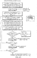
- Fig. 22 outlines the steps of an embodiment of a fully automatic optimization procedure in which the diameter, length, and longitudinal position are optimized simultaneously.
- the user inputs only a target VRR value, VRR max , and the optimization then proceeds iteratively to find the shortest stent that achieves the desired blood flow resistance under the constraints imposed on maximum diameter and maximum malapposition distance.
- the system first creates arrays of area and diameter for each cross-section along the unstented vessel.
- the system creates a lookup table that has the available ranges of stent diameter, length and position.
- the system calculates the VRR and maximum malapposition value.
- the maximum malapposition value equals the distance between the maximum unstented diameter in the segment and the diameter of the stent.
- Table entries that result in VRR values less than VRR max and the maximum malapposition values are retained and then the stent length for each subset is determined.
- the table entry in which the stent length is a minimum defines the optimal stent parameters.
- the recalculation of VRR for a selected stent size needs to be almost instantaneous.
- the most accurate method to find the chosen stent effect of VRR would be to first measure or calculate VRR on the unstented artery using the OCT measurements above or a finite element computational fluid dynamics program and then recalculate VRR using the same finite element computational fluid dynamics program on the proposed stented artery shape.
- most computational fluid dynamics programs will not run fast enough on typical computers to quickly show the affect of the proposed stent.
- a method is needed to have the accuracy of computational fluid dynamics but allow the rapid recalculation of VRR with the proposed placement of a stent.
- a hybrid approach is disclosed here that allows for rapid recalculation.
- algebraic equations are used to determine pressure drop.
- the previously obtained measured or computational fluid dynamics solution is used, modified by the effect of the stent.
- the rapid recalculation is obtained by only using algebraic equations during the stent sizing. Once the stent sizing is complete, a full computational fluid dynamics simulation may be run to obtain an even more accurate answer.
- the initial calculation of VRR on the unstented artery is done using a finite element computational fluid dynamics program. Since there is some time between the end of the imaging procedure and the start of the stent placement, the amount of time this calculation takes is not a limiting constraint.
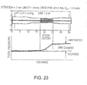
- An important output of the computational fluid dynamics program is a total pressure versus distance graph as shown in the Fig. 23 .
- the simplest way to calculate the change in VRR from the proposed stent addition is simply to subtract the pressure drop in the stented area as shown.
- the VRR display is updated as the stent length and location are changed by the operator.
- Fig. 24 shows an equivalent resistor network model of the pressure drops through the artery.
- the total pressure drop graph from Fig. 23 is broken up into equivalent flow resistors, each spanning a branch or the artery.
- R 0-1 is the flow resistance from the proximal end of the OCT image to the first branch
- R 1-2 is between the first and second branches
- R D-N is between the last branch and the distal end of the OCT scan.
- the calculated pressure drop from the stenosis is set to zero in the stent.
- the Poiseuille pressure drop through the length of the stent is added and the losses at the entrance and exit of the stent due to the diameter change are added.
- the flow calculated with the stenosis by computational fluid dynamics is used to set the resistor values.
- the resistor network in Fig. 24 can be solved by using equations for resistors in series and parallel. An explicit series of equations for flow and thus pressure drop in the stented artery can then be found. The flow division between the branches is readjusted from the resistor network. The flow resistances may be considered linear with flow as a first approximation. A more sophisticated approximation will include the non-linear response of pressure drop with flow.
- the new value of VRR is displayed on the screen as the stent is resized. This calculation happens rapidly as it is simply algebraic equations. This value of VRR is marked as preliminary. The full computational fluid dynamics simulation takes place during the stent resizing and when the calculation is complete the VRR value is be marked as final.
- Fig. 25 and 26 depict the output results of the specific embodiments of the invention.
- the input data were derived from a sequence of OCT images that was recorded in vivo from a branch of a patient's coronary artery.
- the optimization procedure determined the diameters and longitudinal positions of the stents that minimized the hyperemic blood flow resistance, while maintaining good stent apposition.
- Figs. 26a and 26b show the pre- and (predicted) post-stented mean-diameter lumen profiles resulting from the fully automatic optimization procedure for two different target VRR values, VRR max ⁇ 0.05 and VRR max ⁇ 0.02 .
- the input data were derived from a sequence of OCT images recorded in vivo from a branch of a patient's coronary artery. The procedure determined the longitudinal positions, diameters, and minimum lengths of the stents required to reduce VRR below the target values, while maintaining good apposition between the stent and the vessel wall.
- Fig. 27 shows a computer interface with a three dimensional depiction in the top panel of a stent that is not properly placed in the lumen of interest. Two regions of stent malapposition are shown as hatched regions.
- the methods of the invention and features described herein are directed to a computer-based user interface that allows views of OCT in multiple panels. Further, stent malapposition can be shown in three-dimensions.
- the user may reposition the stent to remove the areas of malapposition to simulate proper stent placement prior to implanting a stent in a real patient
- the present invention may be embodied in may different forms, including, but in no way limited to, computer program logic for use with a processor (e.g., a microprocessor, microcontroller, digital signal processor, or general purpose computer), programmable logic for use with a programmable logic device, (e.g., a Field Programmable Gate Array (FPGA) or other PLD), discrete components, integrated circuitry (e.g., an Application Specific Integrated Circuit (ASIC)), or any other means including any combination thereof.
- a processor e.g., a microprocessor, microcontroller, digital signal processor, or general purpose computer
- programmable logic for use with a programmable logic device, (e.g., a Field Programmable Gate Array (FPGA) or other PLD), discrete components, integrated circuitry (e.g., an Application Specific Integrated Circuit (ASIC)), or any other means including any combination thereof.
- FPGA Field Programmable Gate Array
- ASIC Application Specific Integrated Circuit
- some or all of the processing of the data collected using an OCT probe and the processor-based system is implemented as a set of computer program instructions that is converted into a computer executable form, stored as such in a computer readable medium, and executed by a microprocessor under the control of an operating system.
- query response and input data are transformed into processor understandable instructions suitable for generating OCT data, histology images, OCT images, vascular resistance, overlays masks, signal processing, weighting artifact removal, contour detection and other features and embodiments described above.
- Source code may include a series of computer program instructions implemented in any of various programming languages (e.g., an object code, an assembly language, or a high-level language such as Fortran, C, C++, JAVA, or HTML) for use with various operating systems or operating environments.
- the source code may define and use various data structures and communication messages.
- the source code may be in a computer executable form (e.g., via an interpreter), or the source code may be converted (e.g., via a translator, assembler, or compiler) into a computer executable form.
- the computer program may be fixed in any form (e.g., source code form, computer executable form, or an intermediate form) either permanently or transitorily in a tangible storage medium, such as a semiconductor memory device (e.g., a RAM, ROM, PROM, EEPROM, or Flash-Programmable RAM), a magnetic memory device (e.g., a diskette or fixed disk), an optical memory device (e.g., a CD-ROM), a PC card (e.g., PCMCIA card), or other memory device.
- a semiconductor memory device e.g., a RAM, ROM, PROM, EEPROM, or Flash-Programmable RAM
- a magnetic memory device e.g., a diskette or fixed disk
- an optical memory device e.g., a CD-ROM
- PC card e.g., PCMCIA card
- the computer program may be fixed in any form in a signal that is transmittable to a computer using any of various communication technologies, including, but in no way limited to, analog technologies, digital technologies, optical technologies, wireless technologies (e.g., Bluetooth), networking technologies, and internetworking technologies.
- the computer program may be distributed in any form as a removable storage medium with accompanying printed or electronic documentation (e.g., shrink-wrapped software), preloaded with a computer system (e.g., on system ROM or fixed disk), or distributed from a server or electronic bulletin board over the communication system (e.g., the Internet or World Wide Web).
- Hardware logic including programmable logic for use with a programmable logic device
- implementing all or part of the functionality previously described herein may be designed using traditional manual methods, or may be designed, captured, simulated, or documented electronically using various tools, such as Computer Aided Design (CAD), a hardware description language (e.g., VHDL or AHDL), or a PLD programming language (e.g., PALASM, ABEL, or CUPL).
- CAD Computer Aided Design
- a hardware description language e.g., VHDL or AHDL
- PLD programming language e.g., PALASM, ABEL, or CUPL
- Programmable logic may be fixed either permanently or transitorily in a tangible storage medium, such as a semiconductor memory device (e.g., a RAM, ROM, PROM, EEPROM, or Flash-Programmable RAM), a magnetic memory device (e.g., a diskette or fixed disk), an optical memory device (e.g., a CD-ROM), or other memory device.
- a semiconductor memory device e.g., a RAM, ROM, PROM, EEPROM, or Flash-Programmable RAM
- a magnetic memory device e.g., a diskette or fixed disk
- an optical memory device e.g., a CD-ROM
- the programmable logic may be fixed in a signal that is transmittable to a computer using any of various communication technologies, including, but in no way limited to, analog technologies, digital technologies, optical technologies, wireless technologies (e.g., Bluetooth), networking technologies, and internetworking technologies.
- the programmable logic may be distributed as a removable storage medium with accompanying printed or electronic documentation (e.g., shrink-wrapped software), preloaded with a computer system (e.g., on system ROM or fixed disk), or distributed from a server or electronic bulletin board over the communication system (e.g., the Internet or World Wide Web).
- printed or electronic documentation e.g., shrink-wrapped software
- a computer system e.g., on system ROM or fixed disk
- server or electronic bulletin board e.g., the Internet or World Wide Web
- a module refers to software, hardware, or firmware suitable for performing a specific data processing or data transmission task.
- a module refers to a software routine, program, or other memory resident application suitable for receiving, transforming, routing and processing instructions, or various types of data such as OCT scan data, interferometer signal data, clock signals, region of interest types, formulas, and other information of interest.
- Computers and computer systems described herein may include operatively associated computer-readable media such as memory for storing software applications used in obtaining, processing, storing and/or communicating data. It can be appreciated that such memory can be internal, external, remote or local with respect to its operatively associated computer or computer system.
- Memory may also include any means for storing software or other instructions including, for example and without limitation, a hard disk, an optical disk, floppy disk, DVD (digital versatile disc), CD (compact disc), memory stick, flash memory, ROM (read only memory), RAM (random access memory), DRAM (dynamic random access memory), PROM (programmable ROM), EEPROM (extended erasable PROM), and/or other like computer-readable media.
- a hard disk an optical disk, floppy disk, DVD (digital versatile disc), CD (compact disc), memory stick, flash memory, ROM (read only memory), RAM (random access memory), DRAM (dynamic random access memory), PROM (programmable ROM), EEPROM (extended erasable PROM), and/or other like computer-readable media.
- computer-readable memory media applied in association with embodiments of the invention described herein may include any memory medium capable of storing instructions executed by a programmable apparatus. Where applicable, method steps described herein may be embodied or executed as instructions stored on a computer-readable memory medium or memory media. These instructions may be software embodied in various programming languages such as C++, C, Java, and/or a variety of other kinds of software programming languages that may be applied to create instructions in accordance with embodiments of the invention.
Claims (19)
- Procédé informatisé automatisé d'évaluation d'un vaisseau sanguin, le procédé comprenant les étapes consistant à :stocker des mesures intravasculaires dans un dispositif de mémoire électronique, les mesures intravasculaires comprenant des mesures de distance ;générer un ensemble de données à partir de mesures intravasculaires obtenues à l'aide d'un système d'imagerie intravasculaire d'un segment de longueur L au sein du vaisseau sanguin (20), le procédé étant caractérisé par les étapes consistant à :déterminer un rapport de résistance vasculaire, VRR, à l'aide d'un processeur (40) à partir d'au moins une partie de l'ensemble de données ; etdéterminer une caractéristique d'au moins une partie du segment disposée le long de la longueur L en réponse au VRR, où le VRR est un rapport d'une résistance à l'écoulement sanguin d'un segment sténotique à une résistance à l'écoulement total d'une ramification d'un vaisseau sanguin dans laquelle le segment sténotique est situé.
- Procédé selon la revendication 1 où la caractéristique est une lésion sténotique.
- Procédé selon la revendication 2 comprenant en outre une étape consistant à afficher au moins une mesure parmi une mesure numérique ou une mesure graphique d'une longueur d'endoprothèse et d'un diamètre d'endoprothèse utilisés pour traiter la lésion sténotique.
- Procédé selon la revendication 1 comprenant en outre les étapes consistant à :calculer une valeur de réserve de débit fractionnaire, FFR, à partir du VRR ; etdéterminer si la valeur de la FFR indique si un traitement du vaisseau sanguin (20) est nécessaire.
- Procédé selon la revendication 4 comprenant en outre une étape consistant à afficher la valeur de réserve de débit fractionnaire sur un affichage (42) en communication électrique avec le système d'imagerie intravasculaire.
- Procédé selon la revendication 1 où les mesures intravasculaires sont des lignes de balayage obtenues à l'aide d'une sonde d'imagerie intravasculaire de tomographie par cohérence optique (30).
- Procédé selon la revendication 1 où le système d'imagerie intravasculaire est un système de tomographie par cohérence optique (36).
- Procédé selon la revendication 1 où

- Procédé selon la revendication 5 comprenant en outre l'étape consistant à détecter et retirer des artefacts de fil de guidage.
- Procédé selon la revendication 1 comprenant en outre la génération d'une image du vaisseau sanguin (20), où l'image est une image OCT, et la simulation d'une mise en place d'endoprothèse par rapport à celui-ci.
- Procédé selon la revendication 1 où l'ensemble de données comprend une pluralité d'aires en coupe transversale au niveau d'une pluralité de positions le long de la longueur L.
- Procédé automatisé pour quantifier une résistance vasculaire comprenant les étapes consistant à :
stocker un ensemble de trames de données d'image comprenant des données d'imagerie intravasculaire au niveau d'une pluralité de positions le long d'une longueur L d'un segment de vaisseau sanguin ; le procédé étant caractérisé par les étapes consistant à :sélectionner des trames proximale et distale à partir de l'ensemble de trames des données d'imagerie intravasculaire ;déterminer un rapport de résistance vasculaire, VRR, à l'aide d'un processeur (40) et d'au moins une partie de l'ensemble de trames de données ;déterminer une caractéristique d'au moins une partie du segment de vaisseau sanguin disposée le long de la longueur L en réponse au rapport de résistance vasculaire, où le VRR est un rapport d'une résistance à l'écoulement sanguin d'un segment sténotique à une résistance à l'écoulement total d'une ramification d'un vaisseau sanguin dans laquelle le segment sténotique est situé. - Procédé selon la revendication 12 comprenant en outre :le calcul d'une résistance vasculaire réelle du segment de vaisseau sanguin entouré par les trames proximale et distale ;le calcul d'une résistance vasculaire totale du segment de vaisseau sanguin ; etle calcul du rapport de résistance vasculaire à l'aide de la résistance vasculaire réelle et de la résistance vasculaire totale.
- Procédé selon la revendication 13 où ladite étape consistant à calculer la résistance vasculaire réelle comprend les étapes consistant à :extraire des contours luminaux de toutes les trames enfermées par les trames proximale et distale, bornes incluses ;calculer des aires en coupe transversale à partir des contours extraits ;construire un graphique en aires lissées ; etcalculer la résistance vasculaire réelle en réponse au graphique en aires lissées.
- Procédé selon la revendication 13 où ladite étape consistant à calculer la résistance vasculaire totale comprend les étapes consistant à :a. adapter une forme entre lesdites trames proximale et distale ; etb. calculer des aires en coupe transversale de la forme à toutes les positions de trame entourées par lesdites trames proximale et distale, bornes incluses.
- Procédé selon la revendication 12 comprenant en outre un affichage (42) destiné à afficher au moins une mesure parmi une mesure numérique ou mesure graphique de longueur d'endoprothèse utilisée pour traiter une lésion sténotique.
- Procédé selon la revendication 12 comprenant en outre les étapes consistant à :calculer une réserve de débit fractionnaire, FFR, à partir du VRR ; etdéterminer si la valeur de la FFR est significative sur le plan clinique.
- Procédé selon la revendication 12 comprenant en outre la génération d'une image du vaisseau sanguin, où l'image est une image OCT, et la simulation d'une mise en place d'endoprothèse par rapport à celui-ci.
- Procédé selon la revendication 12 où les données d'imagerie intravasculaire sont des données de tomographie par cohérence optique.
Applications Claiming Priority (4)
| Application Number | Priority Date | Filing Date | Title |
|---|---|---|---|
| US24499209P | 2009-09-23 | 2009-09-23 | |
| US33483410P | 2010-05-14 | 2010-05-14 | |
| PCT/US2010/049887 WO2011038044A2 (fr) | 2009-09-23 | 2010-09-22 | Systèmes de collecte de données de mesures de résistance vasculaire et de morphologie de lumière, appareil et procédés |
| EP10763913.0A EP2480124B1 (fr) | 2009-09-23 | 2010-09-22 | Systèmes de collecte de données de mesures de résistance vasculaire et de morphologie de lumière, appareil et procédés |
Related Parent Applications (1)
| Application Number | Title | Priority Date | Filing Date |
|---|---|---|---|
| EP10763913.0A Division EP2480124B1 (fr) | 2009-09-23 | 2010-09-22 | Systèmes de collecte de données de mesures de résistance vasculaire et de morphologie de lumière, appareil et procédés |
Publications (2)
| Publication Number | Publication Date |
|---|---|
| EP3363350A1 EP3363350A1 (fr) | 2018-08-22 |
| EP3363350B1 true EP3363350B1 (fr) | 2019-12-11 |
Family
ID=43332239
Family Applications (3)
| Application Number | Title | Priority Date | Filing Date |
|---|---|---|---|
| EP20140151395 Pending EP2742858A3 (fr) | 2009-09-23 | 2010-09-22 | Systèmes de collecte de données de morphologie du lumen et de mesure de la résistance vasculaire |
| EP10763913.0A Active EP2480124B1 (fr) | 2009-09-23 | 2010-09-22 | Systèmes de collecte de données de mesures de résistance vasculaire et de morphologie de lumière, appareil et procédés |
| EP17202843.3A Active EP3363350B1 (fr) | 2009-09-23 | 2010-09-22 | Morphologie de lumière et systèmes de collecte de données de mesure de résistance vasculaire, appareil et procédés |
Family Applications Before (2)
| Application Number | Title | Priority Date | Filing Date |
|---|---|---|---|
| EP20140151395 Pending EP2742858A3 (fr) | 2009-09-23 | 2010-09-22 | Systèmes de collecte de données de morphologie du lumen et de mesure de la résistance vasculaire |
| EP10763913.0A Active EP2480124B1 (fr) | 2009-09-23 | 2010-09-22 | Systèmes de collecte de données de mesures de résistance vasculaire et de morphologie de lumière, appareil et procédés |
Country Status (7)
| Country | Link |
|---|---|
| US (2) | US9138147B2 (fr) |
| EP (3) | EP2742858A3 (fr) |
| JP (7) | JP5721721B2 (fr) |
| AU (3) | AU2010298333B2 (fr) |
| CA (2) | CA2765407C (fr) |
| ES (1) | ES2660570T3 (fr) |
| WO (1) | WO2011038044A2 (fr) |
Families Citing this family (205)
| Publication number | Priority date | Publication date | Assignee | Title |
|---|---|---|---|---|
| NL1032602C2 (nl) * | 2006-09-29 | 2008-04-01 | Koninkl Philips Electronics Nv | Werkwijzen, systeem en computerprogrammaproduct voor het detecteren van een protrusie. |
| WO2008057573A2 (fr) | 2006-11-08 | 2008-05-15 | Lightlab Imaging, Inc. | Dispositifs et procédés d'imagerie opto-acoustique |
| EP2358269B1 (fr) | 2007-03-08 | 2019-04-10 | Sync-RX, Ltd. | Traitement d'image et activation d'outil pour procédures médicales |
| US11064964B2 (en) | 2007-03-08 | 2021-07-20 | Sync-Rx, Ltd | Determining a characteristic of a lumen by measuring velocity of a contrast agent |
| US11197651B2 (en) | 2007-03-08 | 2021-12-14 | Sync-Rx, Ltd. | Identification and presentation of device-to-vessel relative motion |
| US9968256B2 (en) | 2007-03-08 | 2018-05-15 | Sync-Rx Ltd. | Automatic identification of a tool |
| US9375164B2 (en) | 2007-03-08 | 2016-06-28 | Sync-Rx, Ltd. | Co-use of endoluminal data and extraluminal imaging |
| JP5639764B2 (ja) * | 2007-03-08 | 2014-12-10 | シンク−アールエックス,リミティド | 運動する器官と共に使用するイメージング及びツール |
| US10716528B2 (en) | 2007-03-08 | 2020-07-21 | Sync-Rx, Ltd. | Automatic display of previously-acquired endoluminal images |
| US9629571B2 (en) | 2007-03-08 | 2017-04-25 | Sync-Rx, Ltd. | Co-use of endoluminal data and extraluminal imaging |
| US7813609B2 (en) | 2007-11-12 | 2010-10-12 | Lightlab Imaging, Inc. | Imaging catheter with integrated reference reflector |
| US8200466B2 (en) | 2008-07-21 | 2012-06-12 | The Board Of Trustees Of The Leland Stanford Junior University | Method for tuning patient-specific cardiovascular simulations |
| DE102008045634A1 (de) | 2008-09-03 | 2010-03-04 | Ludwig-Maximilians-Universität München | Wellenlängenabstimmbare Lichtquelle |
| US9101286B2 (en) | 2008-11-18 | 2015-08-11 | Sync-Rx, Ltd. | Apparatus and methods for determining a dimension of a portion of a stack of endoluminal data points |
| US9095313B2 (en) | 2008-11-18 | 2015-08-04 | Sync-Rx, Ltd. | Accounting for non-uniform longitudinal motion during movement of an endoluminal imaging probe |
| US9974509B2 (en) | 2008-11-18 | 2018-05-22 | Sync-Rx Ltd. | Image super enhancement |
| US9144394B2 (en) | 2008-11-18 | 2015-09-29 | Sync-Rx, Ltd. | Apparatus and methods for determining a plurality of local calibration factors for an image |
| US10362962B2 (en) | 2008-11-18 | 2019-07-30 | Synx-Rx, Ltd. | Accounting for skipped imaging locations during movement of an endoluminal imaging probe |
| US11064903B2 (en) | 2008-11-18 | 2021-07-20 | Sync-Rx, Ltd | Apparatus and methods for mapping a sequence of images to a roadmap image |
| US8855744B2 (en) | 2008-11-18 | 2014-10-07 | Sync-Rx, Ltd. | Displaying a device within an endoluminal image stack |
| US9405886B2 (en) | 2009-03-17 | 2016-08-02 | The Board Of Trustees Of The Leland Stanford Junior University | Method for determining cardiovascular information |
| CN102469943A (zh) * | 2009-07-14 | 2012-05-23 | 通用医疗公司 | 用于测量脉管内流动和压力的设备、系统和方法 |
| US8526472B2 (en) | 2009-09-03 | 2013-09-03 | Axsun Technologies, Inc. | ASE swept source with self-tracking filter for OCT medical imaging |
| US8670129B2 (en) | 2009-09-03 | 2014-03-11 | Axsun Technologies, Inc. | Filtered ASE swept source for OCT medical imaging |
| JP5643315B2 (ja) | 2009-09-23 | 2014-12-17 | ライトラボ・イメージング・インコーポレーテッド | 光干渉断層撮影プローブの作動方法、コンピュータシステム、及び光干渉断層撮影データ収集システム |
| WO2011038044A2 (fr) | 2009-09-23 | 2011-03-31 | Lightlab Imaging, Inc. | Systèmes de collecte de données de mesures de résistance vasculaire et de morphologie de lumière, appareil et procédés |
| CA2777562C (fr) | 2009-10-12 | 2016-08-16 | Silicon Valley Medical Instruments, Inc. | Systeme ultrasonore intravasculaire pour une imagerie co-enregistree |
| US8206377B2 (en) * | 2009-12-22 | 2012-06-26 | Lightlab Imaging, Inc. | Torque limiter for an OCT catheter |
| US8926590B2 (en) | 2009-12-22 | 2015-01-06 | Lightlab Imaging, Inc. | Torque limiter for an OCT catheter |
| JP5666617B2 (ja) | 2010-03-17 | 2015-02-12 | ライトラボ・イメージング・インコーポレーテッド | 干渉センシングおよび画像取得システムのための強度雑音を低減する方法および装置 |
| JP5592137B2 (ja) * | 2010-03-30 | 2014-09-17 | テルモ株式会社 | 光画像診断装置及びその表示制御方法 |
| DE102010018679A1 (de) * | 2010-04-28 | 2011-11-03 | Medizinisches Laserzentrum Lübeck GmbH | Vorrichtung mit OCT-System zur Untersuchung und Behandlung lebenden Gewebes unter Erwärmung durch Absorption elektromagnetischer Strahlung |
| US8157742B2 (en) * | 2010-08-12 | 2012-04-17 | Heartflow, Inc. | Method and system for patient-specific modeling of blood flow |
| US8315812B2 (en) | 2010-08-12 | 2012-11-20 | Heartflow, Inc. | Method and system for patient-specific modeling of blood flow |
| GB201100136D0 (en) | 2011-01-06 | 2011-02-23 | Davies Helen C S | Apparatus and method of characterising a narrowing in a filled tube |
| GB201100137D0 (en) | 2011-01-06 | 2011-02-23 | Davies Helen C S | Apparatus and method of assessing a narrowing in a fluid tube |
| US9256933B2 (en) * | 2011-02-08 | 2016-02-09 | Region Nordjylland, Aalborg Sygehus | System for determining flow properties of a blood vessel |
| US8582619B2 (en) | 2011-03-15 | 2013-11-12 | Lightlab Imaging, Inc. | Methods, systems, and devices for timing control in electromagnetic radiation sources |
| JP2012200532A (ja) * | 2011-03-28 | 2012-10-22 | Terumo Corp | 画像診断装置及び表示方法 |
| US9164240B2 (en) | 2011-03-31 | 2015-10-20 | Lightlab Imaging, Inc. | Optical buffering methods, apparatus, and systems for increasing the repetition rate of tunable light sources |
| WO2012166332A1 (fr) * | 2011-05-27 | 2012-12-06 | Lightlab Imaging, Inc. | Systèmes et procédés à base de tomographie par cohérence optique et de pression |
| US9610064B2 (en) | 2011-05-31 | 2017-04-04 | Desmond Adler | Multimodal imaging system, apparatus, and methods |
| JP6099640B2 (ja) | 2011-06-23 | 2017-03-22 | シンク−アールエックス,リミティド | 管腔の背景の鮮明化 |
| US9314584B1 (en) | 2011-06-27 | 2016-04-19 | Bayer Healthcare Llc | Method and apparatus for fractional flow reserve measurements |
| US8582109B1 (en) | 2011-08-01 | 2013-11-12 | Lightlab Imaging, Inc. | Swept mode-hopping laser system, methods, and devices for frequency-domain optical coherence tomography |
| US10648918B2 (en) | 2011-08-03 | 2020-05-12 | Lightlab Imaging, Inc. | Systems, methods and apparatus for determining a fractional flow reserve (FFR) based on the minimum lumen area (MLA) and the constant |
| US9339348B2 (en) | 2011-08-20 | 2016-05-17 | Imperial Colege of Science, Technology and Medicine | Devices, systems, and methods for assessing a vessel |
| US10888232B2 (en) | 2011-08-20 | 2021-01-12 | Philips Image Guided Therapy Corporation | Devices, systems, and methods for assessing a vessel |
| WO2013028612A2 (fr) | 2011-08-20 | 2013-02-28 | Volcano Corporation | Dispositifs, systèmes et procédés pour une représentation visuelle d'un vaisseau et une évaluation d'options de traitement |
| JP6153169B2 (ja) * | 2011-09-21 | 2017-06-28 | 賢哉 那須 | 血管断面形状数値化装置 |
| JP5812785B2 (ja) * | 2011-09-22 | 2015-11-17 | 株式会社トプコン | 光断層画像処理装置及び光断層画像処理装置の作動方法 |
| EP2768868B1 (fr) * | 2011-10-21 | 2018-06-27 | Nissan Chemical Industries, Ltd. | Synthèse améliorée de polymères conjugués par le biais d'une polymérisation oxydante et compositions associées |
| US8953911B1 (en) | 2011-10-28 | 2015-02-10 | Lightlab Imaging, Inc. | Spectroscopic imaging probes, devices, and methods |
| US8831321B1 (en) * | 2011-11-07 | 2014-09-09 | Lightlab Imaging, Inc. | Side branch detection methods, systems and devices |
| US10162932B2 (en) | 2011-11-10 | 2018-12-25 | Siemens Healthcare Gmbh | Method and system for multi-scale anatomical and functional modeling of coronary circulation |
| US8548778B1 (en) | 2012-05-14 | 2013-10-01 | Heartflow, Inc. | Method and system for providing information from a patient-specific model of blood flow |
| WO2013177527A1 (fr) | 2012-05-25 | 2013-11-28 | Acist Medical Systems, Inc. | Systèmes et procédés de mesure d'écoulement de fluide |
| JP6134789B2 (ja) * | 2012-06-26 | 2017-05-24 | シンク−アールエックス,リミティド | 管腔器官における流れに関連する画像処理 |
| ITMI20121156A1 (it) | 2012-06-29 | 2013-12-30 | Consiglio Nazionale Ricerche | Metodo di elaborazione di immagini di tomografia a coerenza ottica |
| EP2687150A1 (fr) * | 2012-07-20 | 2014-01-22 | Canon Kabushiki Kaisha | Procédé, appareil et programme pour détecter une région dans un balayage OCT d'un objet affecté par un artefact de réflexion |
| WO2014036477A1 (fr) | 2012-08-31 | 2014-03-06 | Volcano Corporation | Dispositifs intravasculaires de détection de pression à dérive réduite, et systèmes et procédés associés |
| US20140236011A1 (en) * | 2012-08-31 | 2014-08-21 | General Electric Company | Methods and systems for simultaneous interventional imaging and functional measurements |
| US10398386B2 (en) * | 2012-09-12 | 2019-09-03 | Heartflow, Inc. | Systems and methods for estimating blood flow characteristics from vessel geometry and physiology |
| US10433740B2 (en) | 2012-09-12 | 2019-10-08 | Heartflow, Inc. | Systems and methods for estimating ischemia and blood flow characteristics from vessel geometry and physiology |
| JP6053118B2 (ja) * | 2012-09-18 | 2016-12-27 | 川澄化学工業株式会社 | シミュレーション装置、シミュレーション方法、およびプログラム |
| WO2014045327A1 (fr) * | 2012-09-24 | 2014-03-27 | テルモ株式会社 | Appareil de diagnostic par imagerie et procédé de traitement d'image |
| DE102012217268A1 (de) * | 2012-09-25 | 2013-09-19 | Siemens Aktiengesellschaft | Verfahren und Vorrichtung zur Unterstützung einer Planung einer Stentimplantation |
| US10568586B2 (en) * | 2012-10-05 | 2020-02-25 | Volcano Corporation | Systems for indicating parameters in an imaging data set and methods of use |
| US9858668B2 (en) * | 2012-10-05 | 2018-01-02 | Volcano Corporation | Guidewire artifact removal in images |
| US10070827B2 (en) | 2012-10-05 | 2018-09-11 | Volcano Corporation | Automatic image playback |
| US9943233B2 (en) | 2012-10-24 | 2018-04-17 | Cathworks Ltd. | Automated measurement system and method for coronary artery disease scoring |
| US10595807B2 (en) | 2012-10-24 | 2020-03-24 | Cathworks Ltd | Calculating a fractional flow reserve |
| US10210956B2 (en) | 2012-10-24 | 2019-02-19 | Cathworks Ltd. | Diagnostically useful results in real time |
| US9858387B2 (en) * | 2013-01-15 | 2018-01-02 | CathWorks, LTD. | Vascular flow assessment |
| US11701089B2 (en) | 2012-11-19 | 2023-07-18 | Lightlab Imaging, Inc. | Multimodal imaging systems, probes and methods |
| EP3272282A3 (fr) * | 2012-12-12 | 2018-05-02 | Lightlab Imaging, Inc. | Appareil de détermination automatisée d'un contour de lumière d'un vaisseau sanguin |
| EP2934282B1 (fr) * | 2012-12-20 | 2020-04-29 | Volcano Corporation | Localisation d'images intravasculaires |
| US10588586B2 (en) * | 2013-01-16 | 2020-03-17 | Siemens Healthcare Gmbh | Cardiac analysis based on vessel characteristics |
| US9757591B2 (en) | 2013-02-11 | 2017-09-12 | Bayer Healthcare Llc | Methods and systems for monitoring an automated infusion system |
| US9042613B2 (en) | 2013-03-01 | 2015-05-26 | Heartflow, Inc. | Method and system for determining treatments by modifying patient-specific geometrical models |
| US9424395B2 (en) * | 2013-03-04 | 2016-08-23 | Heartflow, Inc. | Method and system for sensitivity analysis in modeling blood flow characteristics |
| EP2965682A4 (fr) | 2013-03-04 | 2016-11-09 | Terumo Corp | Appareil d'imagerie diagnostique, dispositif de traitement des informations et procédés de commande, programmes et support de stockage lisible par ordinateur associés |
| US9173591B2 (en) | 2013-03-08 | 2015-11-03 | Lightlab Imaging, Inc. | Stent visualization and malapposition detection systems, devices, and methods |
| CN105246402B (zh) * | 2013-03-08 | 2018-10-02 | 光学实验室成像公司 | 支架可视化和贴壁不良检测系统、设备和方法 |
| WO2014163601A1 (fr) | 2013-03-11 | 2014-10-09 | Lightlab Imaging, Inc. | Limiteur de couple de frottement pour cathéter d'imagerie |
| US9351698B2 (en) | 2013-03-12 | 2016-05-31 | Lightlab Imaging, Inc. | Vascular data processing and image registration systems, methods, and apparatuses |
| JP6937267B2 (ja) * | 2013-03-12 | 2021-09-22 | ライトラボ・イメージング・インコーポレーテッド | データ収集システム及びデータ収集システムの制御装置 |
| WO2014142815A1 (fr) * | 2013-03-12 | 2014-09-18 | Lightlab Imaging, Inc. | Système de collecte de données et dispositif de commande de système de collecte de données |
| CN105188550B (zh) * | 2013-03-12 | 2020-06-09 | 光学实验室成像公司 | 血管数据处理和图像配准系统、方法及装置 |
| US9069396B2 (en) | 2013-03-12 | 2015-06-30 | Lightlab Imaging, Inc. | Controller and user interface device, systems, and methods |
| CN105377177B (zh) * | 2013-03-14 | 2018-08-07 | Vida诊断公司 | 肺减容手术的治疗设计 |
| US9833221B2 (en) | 2013-03-15 | 2017-12-05 | Lightlab Imaging, Inc. | Apparatus and method of image registration |
| US9702762B2 (en) * | 2013-03-15 | 2017-07-11 | Lightlab Imaging, Inc. | Calibration and image processing devices, methods, and systems |
| CN105283119B (zh) * | 2013-04-12 | 2018-09-21 | 皇家飞利浦有限公司 | 形状感测超声探头 |
| WO2014182505A1 (fr) | 2013-05-10 | 2014-11-13 | Stenomics, Inc. | Systeme de modelisation et de simulation pour optimisation de traitement de valvule cardiaque prothetique |
| US9195800B2 (en) | 2013-08-16 | 2015-11-24 | Heartflow, Inc. | Systems and methods for identifying personalized vascular implants from patient-specific anatomic data |
| US9842401B2 (en) | 2013-08-21 | 2017-12-12 | Koninklijke Philips N.V. | Segmentation apparatus for interactively segmenting blood vessels in angiographic image data |
| WO2015054232A1 (fr) | 2013-10-07 | 2015-04-16 | Acist Medical Systems, Inc. | Traitement de signal pour imagerie intravasculaire |
| US9092743B2 (en) | 2013-10-23 | 2015-07-28 | Stenomics, Inc. | Machine learning system for assessing heart valves and surrounding cardiovascular tracts |
| EP3061015A2 (fr) | 2013-10-24 | 2016-08-31 | Cathworks Ltd. | Détermination de caractéristiques vasculaires au moyen d'une modélisation par correspondance d'un arbre vasculaire |
| ES2459244B1 (es) * | 2013-10-31 | 2014-11-14 | Galgo Medical, S.L. | Procedimiento para la determinación de la longitud final de stents antes de su colocación |
| KR101578770B1 (ko) | 2013-11-21 | 2015-12-18 | 삼성전자주식회사 | 의료 영상 처리 장치 및 그에 따른 의료 영상 처리 방법 |
| CN105899141A (zh) | 2014-01-10 | 2016-08-24 | 火山公司 | 检测与动脉瘤修复相关联的内漏 |
| US20150196271A1 (en) * | 2014-01-10 | 2015-07-16 | Volcano Corporation | Detecting endoleaks associated with aneurysm repair |
| US9504529B2 (en) | 2014-02-24 | 2016-11-29 | Vida Diagnostics, Inc. | Treatment outcome prediction for lung volume reduction procedures |
| JP6243763B2 (ja) * | 2014-03-14 | 2017-12-06 | テルモ株式会社 | 画像処理装置、画像処理装置の作動方法、及びプログラム |
| CA2944114C (fr) | 2014-04-04 | 2023-09-26 | St. Jude Medical Systems Ab | Systemes, dispositifs et procedes de diagnostic de donnees de pression intravasculaire et de debit |
| WO2015161286A1 (fr) * | 2014-04-17 | 2015-10-22 | The Trustees Of Columbia University In The City Of New York | Technologies pour diagnostiquer des maladies neurologiques ou psychiatriques |
| US20150305631A1 (en) * | 2014-04-25 | 2015-10-29 | Medtronic, Inc. | Real-Time Relationship Between Geometries of an Instrument and a Structure |
| US20170049596A1 (en) * | 2014-04-30 | 2017-02-23 | Stryker Corporation | Implant delivery system and method of use |
| US9754082B2 (en) * | 2014-05-30 | 2017-09-05 | Heartflow, Inc. | Systems and methods for reporting blood flow characteristics |
| US10675003B2 (en) | 2014-07-11 | 2020-06-09 | Acist Medical Systems, Inc. | Intravascular imaging |
| EP3622884A1 (fr) * | 2014-07-24 | 2020-03-18 | Lightlab Imaging, Inc. | Systèmes de visualisation d'endoprothèses et de vaisseaux et de diagnostic, dispositifs et procédés |
| EP3536230B1 (fr) | 2014-08-27 | 2022-03-16 | St. Jude Medical Systems AB | Système pour évaluer un système cardiaque par détermination d'un rapport minimal pd/pa (pression distale/pression artérielle) |
| US11311200B1 (en) | 2014-08-27 | 2022-04-26 | Lightlab Imaging, Inc. | Systems and methods to measure physiological flow in coronary arteries |
| US10499813B2 (en) | 2014-09-12 | 2019-12-10 | Lightlab Imaging, Inc. | Methods, systems and apparatus for temporal calibration of an intravascular imaging system |
| ES2864714T3 (es) * | 2014-12-12 | 2021-10-14 | Lightlab Imaging Inc | Método para detectar y representar visualmente características endovasculares |
| US10646185B2 (en) * | 2015-01-15 | 2020-05-12 | Koninklijke Philips N.V. | iFR-CT |
| ES2578523B1 (es) | 2015-01-26 | 2017-12-28 | Galgo Medical, Sl | Procedimiento, sistema y programa de ordenador para determinar la porosidad de una estructura porosa flexible cuando es sometida a deformación |
| JP6669720B2 (ja) * | 2015-02-25 | 2020-03-18 | テルモ株式会社 | 画像診断装置、その作動方法、プログラム及びコンピュータ可読記憶媒体 |
| US20210345988A1 (en) * | 2015-03-23 | 2021-11-11 | Seshadri Raju | Optimal Sizing of Iliac Vein Stents and Method of Using with 3D Ultrasound |
| EP3282921B1 (fr) | 2015-04-16 | 2022-02-16 | Gentuity LLC | Sondes micro-optiques de neurologie |
| US10646198B2 (en) | 2015-05-17 | 2020-05-12 | Lightlab Imaging, Inc. | Intravascular imaging and guide catheter detection methods and systems |
| EP3297532B1 (fr) | 2015-05-17 | 2022-08-03 | Lightlab Imaging, Inc. | Interfaces de système d'imagerie intravasculaire et procédés de détection d'endoprothèse |
| US10140712B2 (en) | 2015-05-17 | 2018-11-27 | Lightlab Imaging, Inc. | Detection of stent struts relative to side branches |
| US10222956B2 (en) | 2015-05-17 | 2019-03-05 | Lightlab Imaging, Inc. | Intravascular imaging user interface systems and methods |
| US10109058B2 (en) | 2015-05-17 | 2018-10-23 | Lightlab Imaging, Inc. | Intravascular imaging system interfaces and stent detection methods |
| US9996921B2 (en) | 2015-05-17 | 2018-06-12 | LIGHTLAB IMAGING, lNC. | Detection of metal stent struts |
| EP3324830B1 (fr) * | 2015-07-25 | 2023-01-04 | Lightlab Imaging, Inc. | Procédé et système de visualisation de données intravasculaires |
| CA2993458A1 (fr) * | 2015-07-25 | 2017-02-02 | Lightlab Imaging, Inc. | Systemes, procedes et appareils de detection de fil-guide |
| US11031136B2 (en) * | 2015-08-05 | 2021-06-08 | Koninklijke Philips N.V. | Assistance device and method for an interventional hemodynamic measurement |
| US11113812B2 (en) | 2015-08-14 | 2021-09-07 | Elucid Bioimaging Inc. | Quantitative imaging for detecting vulnerable plaque |
| US11071501B2 (en) | 2015-08-14 | 2021-07-27 | Elucid Bioiwaging Inc. | Quantitative imaging for determining time to adverse event (TTE) |
| US10176408B2 (en) | 2015-08-14 | 2019-01-08 | Elucid Bioimaging Inc. | Systems and methods for analyzing pathologies utilizing quantitative imaging |
| US11676359B2 (en) | 2015-08-14 | 2023-06-13 | Elucid Bioimaging Inc. | Non-invasive quantitative imaging biomarkers of atherosclerotic plaque biology |
| US11087459B2 (en) | 2015-08-14 | 2021-08-10 | Elucid Bioimaging Inc. | Quantitative imaging for fractional flow reserve (FFR) |
| US11094058B2 (en) | 2015-08-14 | 2021-08-17 | Elucid Bioimaging Inc. | Systems and method for computer-aided phenotyping (CAP) using radiologic images |
| JP6981967B2 (ja) | 2015-08-31 | 2021-12-17 | ジェンテュイティ・リミテッド・ライアビリティ・カンパニーGentuity, LLC | 撮像プローブおよびデリバリデバイスを含む撮像システム |
| WO2017055228A1 (fr) | 2015-09-29 | 2017-04-06 | Koninklijke Philips N.V. | Estimation du débit, de la résistance ou de la pression à partir de mesures de pression ou de débit et d'une angiographie |
| WO2017056007A1 (fr) * | 2015-09-29 | 2017-04-06 | Imperial Innovations Limited | Dispositifs, systèmes et procédés d'évaluation, planification et traitement d'intervention coronarienne sur la base d'un résultat souhaité |
| JP6818492B2 (ja) * | 2015-10-05 | 2021-01-20 | キヤノンメディカルシステムズ株式会社 | 画像処理装置、画像処理方法、及びプログラム |
| US10909661B2 (en) * | 2015-10-08 | 2021-02-02 | Acist Medical Systems, Inc. | Systems and methods to reduce near-field artifacts |
| US10653393B2 (en) | 2015-10-08 | 2020-05-19 | Acist Medical Systems, Inc. | Intravascular ultrasound imaging with frequency selective imaging methods and systems |
| AU2016339822B9 (en) * | 2015-10-13 | 2021-07-08 | Lightlab Imaging, Inc. | Intravascular imaging system and methods to determine cut plane view angle of side branch |
| WO2017087477A1 (fr) | 2015-11-18 | 2017-05-26 | Lightlab Imaging, Inc. | Détection d'entretoises d'endoprothèse par rapport aux branches latérales |
| CN108633312B (zh) | 2015-11-18 | 2022-11-08 | 光学实验室成像公司 | 一种在x射线图像中的造影云检测方法 |
| CN115998310A (zh) | 2015-11-23 | 2023-04-25 | 光学实验室成像公司 | 血管内图像中的阴影的检测与验证 |
| US11369337B2 (en) * | 2015-12-11 | 2022-06-28 | Acist Medical Systems, Inc. | Detection of disturbed blood flow |
| JP7104632B2 (ja) | 2015-12-31 | 2022-07-21 | アシスト・メディカル・システムズ,インコーポレイテッド | 半自動化画像セグメント化システム及び方法 |
| JP7027331B2 (ja) | 2016-04-14 | 2022-03-01 | ライトラボ・イメージング・インコーポレーテッド | 血管の分枝の識別 |
| IL263066B2 (en) | 2016-05-16 | 2023-09-01 | Cathworks Ltd | Selecting blood vessels from images |
| JP7152955B2 (ja) | 2016-05-16 | 2022-10-13 | アシスト・メディカル・システムズ,インコーポレイテッド | 動作ベースの画像セグメント化のシステムおよび方法 |
| ES2854729T3 (es) | 2016-05-16 | 2021-09-22 | Lightlab Imaging Inc | Método y sistema para la detección de endoprótesis autoexpansible, o stent, intravascular absorbible |
| EP3457930B1 (fr) | 2016-05-16 | 2023-11-15 | Cathworks Ltd. | Système d'évaluation vasculaire |
| CN106073894B (zh) * | 2016-05-31 | 2017-08-08 | 博动医学影像科技(上海)有限公司 | 基于植入虚拟支架的血管压力降数值及血流储备分数的评估方法和系统 |
| CN106073749A (zh) * | 2016-06-06 | 2016-11-09 | 任勇 | 基于静脉支架的血液流速监测装置及其方法 |
| CN109716446B (zh) * | 2016-09-28 | 2023-10-03 | 光学实验室成像公司 | 利用血管表象的支架规划系统及方法 |
| US11179043B2 (en) | 2016-09-30 | 2021-11-23 | Koninklijke Philips N.V. | Apparatus for determining a functional index for stenosis assessment |
| US11659993B2 (en) * | 2016-12-30 | 2023-05-30 | I-Dynamometer GmbH | Method for determining the occurrence of a vascular collapse of a blood vessel in or at the eye as well as a holding device and an ophthalmodynamometry assembly |
| US10842589B2 (en) | 2017-03-21 | 2020-11-24 | Canon U.S.A., Inc. | Method for displaying an anatomical image of a coronary artery on a graphical user interface |
| CN110769731B (zh) | 2017-06-15 | 2022-02-25 | 奥林巴斯株式会社 | 内窥镜系统、内窥镜用处理系统、图像处理方法 |
| EP3659114B1 (fr) | 2017-07-26 | 2024-03-06 | Canon U.S.A., Inc. | Évaluation de mouvement cardiaque à l'aide d'une image d'angiographie |
| US10621748B2 (en) | 2017-10-03 | 2020-04-14 | Canon U.S.A., Inc. | Detecting and displaying stent expansion |
| US11571129B2 (en) | 2017-10-03 | 2023-02-07 | Canon U.S.A., Inc. | Detecting and displaying stent expansion |
| JP7160935B2 (ja) | 2017-11-28 | 2022-10-25 | ジェンテュイティ・リミテッド・ライアビリティ・カンパニー | 撮像システム |
| WO2019173830A1 (fr) * | 2018-03-09 | 2019-09-12 | Emory University | Procédés et systèmes pour déterminer une ou plusieurs caractéristiques hémodynamiques coronaires qui prédisent un infarctus du myocarde |
| JP7325430B2 (ja) * | 2018-03-15 | 2023-08-14 | コーニンクレッカ フィリップス エヌ ヴェ | 管腔内病巣評価及び処置計画のための解剖学的標識の決定及び可視化 |
| WO2019226849A1 (fr) | 2018-05-23 | 2019-11-28 | Acist Medical Systems Inc. | Mesure d'un écoulement à l'aide de données d'image |
| CN112513930A (zh) | 2018-05-29 | 2021-03-16 | 光实验成像公司 | 支架扩张显示、系统和方法 |
| US11382516B2 (en) | 2018-06-08 | 2022-07-12 | Canon U.S.A., Inc. | Apparatuses, methods, and storage mediums for lumen and artifacts detection in one or more images, such as in optical coherence tomography images |
| JP7314183B2 (ja) * | 2018-06-15 | 2023-07-25 | パイ メディカル イメージング ビー ヴイ | 定量的血行動態フロー分析のための方法および装置 |
| CN108742570B (zh) * | 2018-06-20 | 2021-10-01 | 博动医学影像科技(上海)有限公司 | 基于冠脉优势类型获取血管压力差的装置 |
| WO2020000102A1 (fr) * | 2018-06-27 | 2020-01-02 | Opsens Inc. | Évaluation de la fonction hémodynamique par un processus hybride de mesure invasive de la pression et d'imagerie |
| US11145054B2 (en) * | 2018-07-09 | 2021-10-12 | Canon U.S.A., Inc. | Methods and systems for displaying intraluminal images |
| US11080902B2 (en) * | 2018-08-03 | 2021-08-03 | Intuitive Surgical Operations, Inc. | Systems and methods for generating anatomical tree structures |
| US20200129158A1 (en) * | 2018-10-26 | 2020-04-30 | Volcano Corporation | Graphical longitudinal display for intraluminal ultrasound imaging and associated devices, systems, and methods |
| CN109166124B (zh) * | 2018-11-20 | 2021-12-14 | 中南大学 | 一种基于连通区域的视网膜血管形态量化方法 |
| US11250294B2 (en) | 2019-01-13 | 2022-02-15 | Lightlab Imaging, Inc. | Systems and methods for classification of arterial image regions and features thereof |
| WO2020154904A1 (fr) * | 2019-01-29 | 2020-08-06 | 深圳市科曼医疗设备有限公司 | Procédé de mesure automatique du diamètre de vaisseau sanguin dans une image ultrasonore |
| US11819309B2 (en) | 2019-03-17 | 2023-11-21 | Lightlab Imaging, Inc. | Arterial imaging and assessment systems and methods and related user interface based-workflows |
| US10861157B2 (en) | 2019-04-04 | 2020-12-08 | Medtronic Vascular, Inc. | System and methods for determining modified fractional flow reserve values |
| GB201905335D0 (en) * | 2019-04-16 | 2019-05-29 | Sonck Jeroen | Means and devices for assessing coronary artery disease |
| EP3972477A4 (fr) * | 2019-05-21 | 2023-05-24 | Gentuity LLC | Systèmes et procédés pour un traitement de patients basé sur l'oct |
| US11024034B2 (en) | 2019-07-02 | 2021-06-01 | Acist Medical Systems, Inc. | Image segmentation confidence determination |
| KR20210121062A (ko) * | 2019-08-05 | 2021-10-07 | 엘루시드 바이오이미징 아이엔씨. | 형태학적 및 혈관주위 질환 표지자의 조합 평가 |
| US11361481B2 (en) * | 2019-09-18 | 2022-06-14 | Topcon Corporation | 3D shadow reduction signal processing method for optical coherence tomography (OCT) images |
| CA3152545A1 (fr) | 2019-09-20 | 2021-03-25 | Bard Access Systems, Inc. | Outils et procedes de detection automatique de vaisseaux sanguins |
| US11963740B2 (en) * | 2019-12-05 | 2024-04-23 | Canon U.S.A., Inc. | Lumen, stent, and/or artifact detection in one or more images, such as in optical coherence tomography images |
| US20230008714A1 (en) * | 2019-12-10 | 2023-01-12 | Philips Image Guided Therapy Corporation | Intraluminal image-based vessel diameter determination and associated devices, systems, and methods |
| US20210196221A1 (en) * | 2019-12-25 | 2021-07-01 | Canon Medical Systems Corporation | Medical image processing apparatus, recording medium, and system |
| JPWO2021200985A1 (fr) * | 2020-03-30 | 2021-10-07 | ||
| WO2021199960A1 (fr) * | 2020-03-30 | 2021-10-07 | テルモ株式会社 | Programme, procédé de traitement d'informations, et système de traitement d'informations |
| US11875459B2 (en) | 2020-04-07 | 2024-01-16 | Vida Diagnostics, Inc. | Subject specific coordinatization and virtual navigation systems and methods |
| JP7356714B2 (ja) | 2020-05-25 | 2023-10-05 | 国立大学法人山口大学 | 画像処理装置と画像処理プログラムと画像処理方法 |
| US11922633B2 (en) | 2020-06-30 | 2024-03-05 | Canon U.S.A., Inc. | Real-time lumen distance calculation based on three-dimensional (3D) A-line signal data |
| WO2022020351A1 (fr) | 2020-07-21 | 2022-01-27 | Bard Access Systems, Inc. | Système, procédé et appareil de poursuite magnétique de sonde ultrasonore et génération de visualisation 3d de celle-ci |
| US11633534B2 (en) | 2020-08-18 | 2023-04-25 | Acist Medical Systems, Inc. | Angiogram injections using electrocardiographic synchronization |
| WO2022051657A1 (fr) | 2020-09-03 | 2022-03-10 | Bard Access Systems, Inc. | Procédés et systèmes ultrasonores portables |
| US11925505B2 (en) | 2020-09-25 | 2024-03-12 | Bard Access Systems, Inc. | Minimum catheter length tool |
| WO2022071265A1 (fr) * | 2020-09-29 | 2022-04-07 | テルモ株式会社 | Programme, et dispositif et procédé de traitement d'informations |
| JPWO2022071328A1 (fr) * | 2020-09-29 | 2022-04-07 | ||
| CN112932434B (zh) * | 2021-01-29 | 2023-12-05 | 苏州润迈德医疗科技有限公司 | 获取流量损失模型、损失比、供血能力的方法和系统 |
| CN113040812B (zh) * | 2021-02-03 | 2023-08-22 | 上海联影医疗科技股份有限公司 | 医学图像分析方法、装置、计算机设备和存储介质 |
| CN112927212B (zh) * | 2021-03-11 | 2023-10-27 | 上海移视网络科技有限公司 | 基于深度学习的oct心血管斑块自动识别与分析方法 |
| US11779221B2 (en) | 2021-06-18 | 2023-10-10 | Canon U.S.A., Inc. | Apparatus, method and storage medium for lumen curve simplification for editing in one or more images, such as in optical coherence tomography images |
Family Cites Families (103)
| Publication number | Priority date | Publication date | Assignee | Title |
|---|---|---|---|---|
| US5662109A (en) | 1990-12-14 | 1997-09-02 | Hutson; William H. | Method and system for multi-dimensional imaging and analysis for early detection of diseased tissue |
| US5054492A (en) | 1990-12-17 | 1991-10-08 | Cardiovascular Imaging Systems, Inc. | Ultrasonic imaging catheter having rotational image correlation |
| US5956355A (en) | 1991-04-29 | 1999-09-21 | Massachusetts Institute Of Technology | Method and apparatus for performing optical measurements using a rapidly frequency-tuned laser |
| US6134003A (en) | 1991-04-29 | 2000-10-17 | Massachusetts Institute Of Technology | Method and apparatus for performing optical measurements using a fiber optic imaging guidewire, catheter or endoscope |
| US6111645A (en) | 1991-04-29 | 2000-08-29 | Massachusetts Institute Of Technology | Grating based phase control optical delay line |
| US5465147A (en) | 1991-04-29 | 1995-11-07 | Massachusetts Institute Of Technology | Method and apparatus for acquiring images using a ccd detector array and no transverse scanner |
| US5748598A (en) | 1995-12-22 | 1998-05-05 | Massachusetts Institute Of Technology | Apparatus and methods for reading multilayer storage media using short coherence length sources |
| US6501551B1 (en) | 1991-04-29 | 2002-12-31 | Massachusetts Institute Of Technology | Fiber optic imaging endoscope interferometer with at least one faraday rotator |
| WO1992019930A1 (fr) | 1991-04-29 | 1992-11-12 | Massachusetts Institute Of Technology | Procede et appareil d'imagerie optique et de mesure |
| US6485413B1 (en) | 1991-04-29 | 2002-11-26 | The General Hospital Corporation | Methods and apparatus for forward-directed optical scanning instruments |
| US6564087B1 (en) | 1991-04-29 | 2003-05-13 | Massachusetts Institute Of Technology | Fiber optic needle probes for optical coherence tomography imaging |
| JP3167367B2 (ja) * | 1991-09-09 | 2001-05-21 | 株式会社東芝 | 循環器診断装置 |
| US5325449A (en) | 1992-05-15 | 1994-06-28 | David Sarnoff Research Center, Inc. | Method for fusing images and apparatus therefor |
| US5509093A (en) | 1993-10-13 | 1996-04-16 | Micron Optics, Inc. | Temperature compensated fiber fabry-perot filters |
| US5531227A (en) | 1994-01-28 | 1996-07-02 | Schneider Medical Technologies, Inc. | Imaging device and method |
| US5797849A (en) | 1995-03-28 | 1998-08-25 | Sonometrics Corporation | Method for carrying out a medical procedure using a three-dimensional tracking and imaging system |
| US5619368A (en) | 1995-05-16 | 1997-04-08 | Massachusetts Inst. Of Technology | Optical frequency shifter |
| WO1997001167A1 (fr) | 1995-06-21 | 1997-01-09 | Massachusetts Institute Of Technology | Appareil et procede permettant d'acceder a des donnees enregistrees sur des supports optiques multichouches |
| US5810007A (en) | 1995-07-26 | 1998-09-22 | Associates Of The Joint Center For Radiation Therapy, Inc. | Ultrasound localization and image fusion for the treatment of prostate cancer |
| US5771895A (en) | 1996-02-12 | 1998-06-30 | Slager; Cornelis J. | Catheter for obtaining three-dimensional reconstruction of a vascular lumen and wall |
| US6148095A (en) | 1997-09-08 | 2000-11-14 | University Of Iowa Research Foundation | Apparatus and method for determining three-dimensional representations of tortuous vessels |
| US5989189A (en) | 1997-10-24 | 1999-11-23 | Mentor Corporation | Ophthalmic ultrasound imaging |
| US20020161351A1 (en) | 1998-09-01 | 2002-10-31 | Samson Wilfred J. | Method and apparatus for treating acute myocardial infarction with selective hypothermic perfusion |
| US6191862B1 (en) | 1999-01-20 | 2001-02-20 | Lightlab Imaging, Llc | Methods and apparatus for high speed longitudinal scanning in imaging systems |
| US6385332B1 (en) | 1999-02-19 | 2002-05-07 | The John P. Roberts Research Institute | Automated segmentation method for 3-dimensional ultrasound |
| US6471656B1 (en) | 1999-06-25 | 2002-10-29 | Florence Medical Ltd | Method and system for pressure based measurements of CFR and additional clinical hemodynamic parameters |
| US7343195B2 (en) * | 1999-05-18 | 2008-03-11 | Mediguide Ltd. | Method and apparatus for real time quantitative three-dimensional image reconstruction of a moving organ and intra-body navigation |
| US6381350B1 (en) | 1999-07-02 | 2002-04-30 | The Cleveland Clinic Foundation | Intravascular ultrasonic analysis using active contour method and system |
| US6445939B1 (en) | 1999-08-09 | 2002-09-03 | Lightlab Imaging, Llc | Ultra-small optical probes, imaging optics, and methods for using same |
| JP4405002B2 (ja) | 1999-09-10 | 2010-01-27 | 阿部 慎一 | ステントグラフト設計装置 |
| US6785409B1 (en) | 2000-10-24 | 2004-08-31 | Koninklijke Philips Electronics, N.V. | Segmentation method and apparatus for medical images using diffusion propagation, pixel classification, and mathematical morphology |
| WO2002036015A1 (fr) | 2000-10-30 | 2002-05-10 | The General Hospital Corporation | Procedes et systemes optiques d'analyse de tissus |
| US20020115931A1 (en) | 2001-02-21 | 2002-08-22 | Strauss H. William | Localizing intravascular lesions on anatomic images |
| US6768756B2 (en) | 2001-03-12 | 2004-07-27 | Axsun Technologies, Inc. | MEMS membrane with integral mirror/lens |
| US6570659B2 (en) | 2001-03-16 | 2003-05-27 | Lightlab Imaging, Llc | Broadband light source system and method and light source combiner |
| US6552796B2 (en) | 2001-04-06 | 2003-04-22 | Lightlab Imaging, Llc | Apparatus and method for selective data collection and signal to noise ratio enhancement using optical coherence tomography |
| US6585660B2 (en) * | 2001-05-18 | 2003-07-01 | Jomed Inc. | Signal conditioning device for interfacing intravascular sensors having varying operational characteristics to a physiology monitor |
| US7532920B1 (en) | 2001-05-31 | 2009-05-12 | Advanced Cardiovascular Systems, Inc. | Guidewire with optical fiber |
| US7329223B1 (en) | 2001-05-31 | 2008-02-12 | Abbott Cardiovascular Systems Inc. | Catheter with optical fiber sensor |
| US6706004B2 (en) | 2001-05-31 | 2004-03-16 | Infraredx, Inc. | Balloon catheter |
| US6697667B1 (en) | 2001-05-31 | 2004-02-24 | Advanced Cardiovascular Systems, Inc. | Apparatus and method for locating coronary sinus |
| US6716178B1 (en) | 2001-05-31 | 2004-04-06 | Advanced Cardiovascular Systems, Inc. | Apparatus and method for performing thermal and laser doppler velocimetry measurements |
| US6879851B2 (en) | 2001-06-07 | 2005-04-12 | Lightlab Imaging, Llc | Fiber optic endoscopic gastrointestinal probe |
| US6947040B2 (en) | 2001-10-23 | 2005-09-20 | Siemens Corporate Research, Inc. | Vessel detection by mean shift based ray propagation |
| US6868736B2 (en) | 2002-02-22 | 2005-03-22 | Sentec Corporation | Ultra-miniature optical pressure sensing system |
| US7134994B2 (en) | 2002-05-20 | 2006-11-14 | Volcano Corporation | Multipurpose host system for invasive cardiovascular diagnostic measurement acquisition and display |
| US6891984B2 (en) | 2002-07-25 | 2005-05-10 | Lightlab Imaging, Llc | Scanning miniature optical probes with optical distortion correction and rotational control |
| US7359554B2 (en) | 2002-08-26 | 2008-04-15 | Cleveland Clinic Foundation | System and method for identifying a vascular border |
| US7794230B2 (en) * | 2002-09-10 | 2010-09-14 | University Of Vermont And State Agricultural College | Mathematical circulatory system model |
| EP1576566B1 (fr) * | 2002-12-03 | 2018-06-13 | Mentice AB | Système de simulation d'intervention |
| WO2004051579A2 (fr) | 2002-12-04 | 2004-06-17 | Philips Intellectual Property & Standards Gmbh | Appareil et methode d'aide a la navigation d'un catheter dans un vaisseau sanguin |
| ATE441360T1 (de) | 2003-02-25 | 2009-09-15 | Koninkl Philips Electronics Nv | Intravaskuläre bilddarstellung |
| WO2004082738A2 (fr) * | 2003-03-13 | 2004-09-30 | Medtronic Vascular, Inc. | Catheters de penetration a guidage optique et leur mode d'utilisation |
| JP4421203B2 (ja) * | 2003-03-20 | 2010-02-24 | 株式会社東芝 | 管腔状構造体の解析処理装置 |
| US20100076320A1 (en) | 2003-04-25 | 2010-03-25 | Lightlab Imaging, Llc | Flush catheter with flow directing sheath |
| US7241286B2 (en) | 2003-04-25 | 2007-07-10 | Lightlab Imaging, Llc | Flush catheter with flow directing sheath |
| US7376455B2 (en) * | 2003-05-22 | 2008-05-20 | Scimed Life Systems, Inc. | Systems and methods for dynamic optical imaging |
| DE10325298B4 (de) | 2003-06-04 | 2007-07-05 | Siemens Ag | Verfahren und Vorrichtung zur Erfassung der Rauigkeit von Gefäßen |
| AU2004268576A1 (en) * | 2003-08-21 | 2005-03-10 | Ischem Corporation | Automated methods and systems for vascular plaque detection and analysis |
| EP3009815B1 (fr) | 2003-10-27 | 2022-09-07 | The General Hospital Corporation | Procédé et appareil pour réaliser l'imagerie optique à l'aide d'une interférométrie de domaine de fréquence |
| CA2449080A1 (fr) | 2003-11-13 | 2005-05-13 | Centre Hospitalier De L'universite De Montreal - Chum | Appareil et methode de segmentation d'images intravasculaires par cheminement rapide au moyen d'ultrasons |
| JP4602993B2 (ja) | 2004-01-16 | 2010-12-22 | ボストン サイエンティフィック リミテッド | 医用撮像のための方法及び装置 |
| US7215802B2 (en) * | 2004-03-04 | 2007-05-08 | The Cleveland Clinic Foundation | System and method for vascular border detection |
| US7397935B2 (en) * | 2004-05-10 | 2008-07-08 | Mediguide Ltd. | Method for segmentation of IVUS image sequences |
| DE102004024334A1 (de) * | 2004-05-17 | 2005-12-22 | Pulsion Medical Systems Ag | Vorrichtung zur Ermittlung eines hämodynamischen Parameters |
| WO2006024015A1 (fr) | 2004-08-24 | 2006-03-02 | The General Hospital Corporation | Procédé et dispositif d'imagerie de segments de vaisseaux |
| WO2006037001A1 (fr) | 2004-09-24 | 2006-04-06 | Lightlab Imaging, Inc. | Dispositifs et procedes d'occlusion permettant d'empecher la circulation de liquides |
| US8983582B2 (en) * | 2004-12-20 | 2015-03-17 | Advanced Cardiovascular Systems, Inc. | Methods and apparatuses for positioning within an internal channel |
| EP1835855B1 (fr) | 2005-01-11 | 2017-04-05 | Volcano Corporation | Co-enregistrement d'images vasculaires |
| WO2006079078A2 (fr) | 2005-01-20 | 2006-07-27 | Massachusetts Institute Of Technology | Procedes et appareil de verrouillage de mode |
| US8315282B2 (en) | 2005-01-20 | 2012-11-20 | Massachusetts Institute Of Technology | Fourier domain mode locking: method and apparatus for control and improved performance |
| WO2006079100A2 (fr) | 2005-01-24 | 2006-07-27 | Thorlabs, Inc. | Laser multimode compact a balayage spectral rapide |
| WO2006086700A2 (fr) | 2005-02-10 | 2006-08-17 | Lightlab Imaging, Inc. | Appareil de tomographie a coherence optique et procedes associes |
| US7892177B2 (en) * | 2005-02-28 | 2011-02-22 | Scimed Life Systems, Inc. | Systems and methods for estimating the length and position of a stent to be applied within a patient |
| US7415049B2 (en) | 2005-03-28 | 2008-08-19 | Axsun Technologies, Inc. | Laser with tilted multi spatial mode resonator tuning element |
| EP1903944B1 (fr) | 2005-06-24 | 2017-04-19 | Volcano Corporation | Co-registration de donnees d'images graphiques representant des elements vasculaires tridimensionnels |
| DE102005032961A1 (de) | 2005-07-14 | 2007-01-18 | Siemens Ag | Verfahren und Vorrichtung zur Erzeugung eines Bildes mittels optischer Kohärenztomographie |
| EP1928306B1 (fr) | 2005-09-29 | 2021-01-13 | General Hospital Corporation | Systèmes et procedes de tomographie par cohérence optique incluant une imagerie microscopique par fluorescence d'une ou plusieurs structures biologiques |
| US7450241B2 (en) | 2005-09-30 | 2008-11-11 | Infraredx, Inc. | Detecting vulnerable plaque |
| JP5600241B2 (ja) | 2005-10-13 | 2014-10-01 | ヴォルケイノウ・コーポレーション | コンポーネントベースのカテーテル・ラボラトリ血管内超音波システム |
| US7729746B2 (en) | 2005-11-04 | 2010-06-01 | Siemens Aktiengesellschaft | Three-dimensional co-registration between intravascular and angiographic data |
| US7593559B2 (en) | 2005-11-18 | 2009-09-22 | Duke University | Method and system of coregistrating optical coherence tomography (OCT) with other clinical tests |
| US7801343B2 (en) | 2005-11-29 | 2010-09-21 | Siemens Medical Solutions Usa, Inc. | Method and apparatus for inner wall extraction and stent strut detection using intravascular optical coherence tomography imaging |
| US7650179B2 (en) * | 2005-12-09 | 2010-01-19 | Siemens Aktiengesellschaft | Computerized workflow method for stent planning and stenting procedure |
| US8184367B2 (en) * | 2006-02-15 | 2012-05-22 | University Of Central Florida Research Foundation | Dynamically focused optical instrument |
| WO2007109771A2 (fr) | 2006-03-22 | 2007-09-27 | Volcano Corporation | Analyse de lésions automatisée fondée sur une caractérisation automatique des plaques en fonction d'un critère de classification |
| US7785286B2 (en) | 2006-03-30 | 2010-08-31 | Volcano Corporation | Method and system for imaging, diagnosing, and/or treating an area of interest in a patient's body |
| US7831078B2 (en) * | 2006-07-24 | 2010-11-09 | Siemens Medical Solutions Usa, Inc. | System and method for statistical shape model based segmentation of intravascular ultrasound and optical coherence tomography images |
| US8029447B2 (en) | 2006-10-10 | 2011-10-04 | Volcano Corporation | Multipurpose host system for invasive cardiovascular diagnostic measurement acquisition including an enhanced dynamically configured graphical display |
| US8223143B2 (en) | 2006-10-27 | 2012-07-17 | Carl Zeiss Meditec, Inc. | User interface for efficiently displaying relevant OCT imaging data |
| WO2008057573A2 (fr) | 2006-11-08 | 2008-05-15 | Lightlab Imaging, Inc. | Dispositifs et procédés d'imagerie opto-acoustique |
| JPWO2008081653A1 (ja) * | 2006-12-28 | 2010-04-30 | テルモ株式会社 | 光プローブ |
| ES2534572T3 (es) | 2007-01-10 | 2015-04-24 | Lightlab Imaging, Inc. | Métodos y aparato para tomografía de coherencia óptica de fuente de barrido |
| JP2009022733A (ja) * | 2007-06-20 | 2009-02-05 | Toshiba Corp | 医用診断支援装置、医用診断支援方法、及び放射線診断装置 |
| US7813609B2 (en) | 2007-11-12 | 2010-10-12 | Lightlab Imaging, Inc. | Imaging catheter with integrated reference reflector |
| US8582934B2 (en) | 2007-11-12 | 2013-11-12 | Lightlab Imaging, Inc. | Miniature optical elements for fiber-optic beam shaping |
| JP5002429B2 (ja) * | 2007-11-20 | 2012-08-15 | テルモ株式会社 | 光干渉断層画像診断装置 |
| JP5112021B2 (ja) | 2007-11-26 | 2013-01-09 | 株式会社東芝 | 血管内画像診断装置及び血管内画像診断システム |
| ES2517915T3 (es) | 2008-06-02 | 2014-11-04 | Lightlab Imaging, Inc. | Métodos cuantitativos para obtener características de un tejido a partir de imágenes de tomografía por coherencia óptica |
| EP2344020B1 (fr) | 2008-10-14 | 2020-05-20 | Lightlab Imaging, Inc. | Détection de support d'endoprothèse et de mesure afférente, et affichage au moyen de la tomographie par cohérence optique |
| JP5643315B2 (ja) | 2009-09-23 | 2014-12-17 | ライトラボ・イメージング・インコーポレーテッド | 光干渉断層撮影プローブの作動方法、コンピュータシステム、及び光干渉断層撮影データ収集システム |
| WO2011038044A2 (fr) | 2009-09-23 | 2011-03-31 | Lightlab Imaging, Inc. | Systèmes de collecte de données de mesures de résistance vasculaire et de morphologie de lumière, appareil et procédés |
| US8206377B2 (en) | 2009-12-22 | 2012-06-26 | Lightlab Imaging, Inc. | Torque limiter for an OCT catheter |
-
2010
- 2010-09-22 WO PCT/US2010/049887 patent/WO2011038044A2/fr active Application Filing
- 2010-09-22 EP EP20140151395 patent/EP2742858A3/fr active Pending
- 2010-09-22 EP EP10763913.0A patent/EP2480124B1/fr active Active
- 2010-09-22 CA CA2765407A patent/CA2765407C/fr active Active
- 2010-09-22 CA CA2926666A patent/CA2926666C/fr active Active
- 2010-09-22 JP JP2012531008A patent/JP5721721B2/ja active Active
- 2010-09-22 EP EP17202843.3A patent/EP3363350B1/fr active Active
- 2010-09-22 US US12/888,347 patent/US9138147B2/en active Active
- 2010-09-22 ES ES10763913.0T patent/ES2660570T3/es active Active
- 2010-09-22 AU AU2010298333A patent/AU2010298333B2/en active Active
-
2012
- 2012-09-14 US US13/617,441 patent/US9572495B2/en active Active
-
2013
- 2013-03-28 JP JP2013070193A patent/JP5635149B2/ja active Active
-
2014
- 2014-07-17 AU AU2014204480A patent/AU2014204480B2/en active Active
- 2014-07-30 JP JP2014155458A patent/JP5987025B2/ja active Active
-
2016
- 2016-07-07 AU AU2016204714A patent/AU2016204714B2/en active Active
- 2016-08-08 JP JP2016155715A patent/JP6283399B2/ja active Active
-
2018
- 2018-01-26 JP JP2018011426A patent/JP6845167B2/ja active Active
-
2020
- 2020-12-09 JP JP2020203808A patent/JP7203077B2/ja active Active
-
2022
- 2022-12-26 JP JP2022208185A patent/JP2023027392A/ja active Pending
Non-Patent Citations (1)
| Title |
|---|
| None * |
Also Published As
Similar Documents
| Publication | Publication Date | Title |
|---|---|---|
| US20230165471A1 (en) | Lumen Morphology And Vascular Resistance Measurements Data Collection Systems Apparatus And Methods | |
| JP7203077B2 (ja) | 血管内画像化システムの作動方法 |
Legal Events
| Date | Code | Title | Description |
|---|---|---|---|
| PUAI | Public reference made under article 153(3) epc to a published international application that has entered the european phase |
Free format text: ORIGINAL CODE: 0009012 |
|
| STAA | Information on the status of an ep patent application or granted ep patent |
Free format text: STATUS: THE APPLICATION HAS BEEN PUBLISHED |
|
| AC | Divisional application: reference to earlier application |
Ref document number: 2480124 Country of ref document: EP Kind code of ref document: P |
|
| AK | Designated contracting states |
Kind code of ref document: A1 Designated state(s): AL AT BE BG CH CY CZ DE DK EE ES FI FR GB GR HR HU IE IS IT LI LT LU LV MC MK MT NL NO PL PT RO SE SI SK SM TR |
|
| STAA | Information on the status of an ep patent application or granted ep patent |
Free format text: STATUS: REQUEST FOR EXAMINATION WAS MADE |
|
| 17P | Request for examination filed |
Effective date: 20190220 |
|
| RBV | Designated contracting states (corrected) |
Designated state(s): AL AT BE BG CH CY CZ DE DK EE ES FI FR GB GR HR HU IE IS IT LI LT LU LV MC MK MT NL NO PL PT RO SE SI SK SM TR |
|
| GRAP | Despatch of communication of intention to grant a patent |
Free format text: ORIGINAL CODE: EPIDOSNIGR1 |
|
| STAA | Information on the status of an ep patent application or granted ep patent |
Free format text: STATUS: GRANT OF PATENT IS INTENDED |
|
| INTG | Intention to grant announced |
Effective date: 20190705 |
|
| GRAS | Grant fee paid |
Free format text: ORIGINAL CODE: EPIDOSNIGR3 |
|
| GRAA | (expected) grant |
Free format text: ORIGINAL CODE: 0009210 |
|
| STAA | Information on the status of an ep patent application or granted ep patent |
Free format text: STATUS: THE PATENT HAS BEEN GRANTED |
|
| AC | Divisional application: reference to earlier application |
Ref document number: 2480124 Country of ref document: EP Kind code of ref document: P |
|
| AK | Designated contracting states |
Kind code of ref document: B1 Designated state(s): AL AT BE BG CH CY CZ DE DK EE ES FI FR GB GR HR HU IE IS IT LI LT LU LV MC MK MT NL NO PL PT RO SE SI SK SM TR |
|
| REG | Reference to a national code |
Ref country code: GB Ref legal event code: FG4D |
|
| REG | Reference to a national code |
Ref country code: CH Ref legal event code: EP |
|
| REG | Reference to a national code |
Ref country code: AT Ref legal event code: REF Ref document number: 1211323 Country of ref document: AT Kind code of ref document: T Effective date: 20191215 |
|
| REG | Reference to a national code |
Ref country code: DE Ref legal event code: R096 Ref document number: 602010062390 Country of ref document: DE |
|
| REG | Reference to a national code |
Ref country code: IE Ref legal event code: FG4D |
|
| REG | Reference to a national code |
Ref country code: NL Ref legal event code: MP Effective date: 20191211 |
|
| REG | Reference to a national code |
Ref country code: LT Ref legal event code: MG4D |
|
| PG25 | Lapsed in a contracting state [announced via postgrant information from national office to epo] |
Ref country code: LT Free format text: LAPSE BECAUSE OF FAILURE TO SUBMIT A TRANSLATION OF THE DESCRIPTION OR TO PAY THE FEE WITHIN THE PRESCRIBED TIME-LIMIT Effective date: 20191211 Ref country code: GR Free format text: LAPSE BECAUSE OF FAILURE TO SUBMIT A TRANSLATION OF THE DESCRIPTION OR TO PAY THE FEE WITHIN THE PRESCRIBED TIME-LIMIT Effective date: 20200312 Ref country code: NO Free format text: LAPSE BECAUSE OF FAILURE TO SUBMIT A TRANSLATION OF THE DESCRIPTION OR TO PAY THE FEE WITHIN THE PRESCRIBED TIME-LIMIT Effective date: 20200311 Ref country code: SE Free format text: LAPSE BECAUSE OF FAILURE TO SUBMIT A TRANSLATION OF THE DESCRIPTION OR TO PAY THE FEE WITHIN THE PRESCRIBED TIME-LIMIT Effective date: 20191211 Ref country code: LV Free format text: LAPSE BECAUSE OF FAILURE TO SUBMIT A TRANSLATION OF THE DESCRIPTION OR TO PAY THE FEE WITHIN THE PRESCRIBED TIME-LIMIT Effective date: 20191211 Ref country code: FI Free format text: LAPSE BECAUSE OF FAILURE TO SUBMIT A TRANSLATION OF THE DESCRIPTION OR TO PAY THE FEE WITHIN THE PRESCRIBED TIME-LIMIT Effective date: 20191211 Ref country code: BG Free format text: LAPSE BECAUSE OF FAILURE TO SUBMIT A TRANSLATION OF THE DESCRIPTION OR TO PAY THE FEE WITHIN THE PRESCRIBED TIME-LIMIT Effective date: 20200311 |
|
| PG25 | Lapsed in a contracting state [announced via postgrant information from national office to epo] |
Ref country code: HR Free format text: LAPSE BECAUSE OF FAILURE TO SUBMIT A TRANSLATION OF THE DESCRIPTION OR TO PAY THE FEE WITHIN THE PRESCRIBED TIME-LIMIT Effective date: 20191211 |
|
| PG25 | Lapsed in a contracting state [announced via postgrant information from national office to epo] |
Ref country code: AL Free format text: LAPSE BECAUSE OF FAILURE TO SUBMIT A TRANSLATION OF THE DESCRIPTION OR TO PAY THE FEE WITHIN THE PRESCRIBED TIME-LIMIT Effective date: 20191211 |
|
| PG25 | Lapsed in a contracting state [announced via postgrant information from national office to epo] |
Ref country code: EE Free format text: LAPSE BECAUSE OF FAILURE TO SUBMIT A TRANSLATION OF THE DESCRIPTION OR TO PAY THE FEE WITHIN THE PRESCRIBED TIME-LIMIT Effective date: 20191211 Ref country code: PT Free format text: LAPSE BECAUSE OF FAILURE TO SUBMIT A TRANSLATION OF THE DESCRIPTION OR TO PAY THE FEE WITHIN THE PRESCRIBED TIME-LIMIT Effective date: 20200506 Ref country code: ES Free format text: LAPSE BECAUSE OF FAILURE TO SUBMIT A TRANSLATION OF THE DESCRIPTION OR TO PAY THE FEE WITHIN THE PRESCRIBED TIME-LIMIT Effective date: 20191211 Ref country code: CZ Free format text: LAPSE BECAUSE OF FAILURE TO SUBMIT A TRANSLATION OF THE DESCRIPTION OR TO PAY THE FEE WITHIN THE PRESCRIBED TIME-LIMIT Effective date: 20191211 Ref country code: NL Free format text: LAPSE BECAUSE OF FAILURE TO SUBMIT A TRANSLATION OF THE DESCRIPTION OR TO PAY THE FEE WITHIN THE PRESCRIBED TIME-LIMIT Effective date: 20191211 Ref country code: RO Free format text: LAPSE BECAUSE OF FAILURE TO SUBMIT A TRANSLATION OF THE DESCRIPTION OR TO PAY THE FEE WITHIN THE PRESCRIBED TIME-LIMIT Effective date: 20191211 |
|
| PG25 | Lapsed in a contracting state [announced via postgrant information from national office to epo] |
Ref country code: SM Free format text: LAPSE BECAUSE OF FAILURE TO SUBMIT A TRANSLATION OF THE DESCRIPTION OR TO PAY THE FEE WITHIN THE PRESCRIBED TIME-LIMIT Effective date: 20191211 Ref country code: IS Free format text: LAPSE BECAUSE OF FAILURE TO SUBMIT A TRANSLATION OF THE DESCRIPTION OR TO PAY THE FEE WITHIN THE PRESCRIBED TIME-LIMIT Effective date: 20200411 Ref country code: SK Free format text: LAPSE BECAUSE OF FAILURE TO SUBMIT A TRANSLATION OF THE DESCRIPTION OR TO PAY THE FEE WITHIN THE PRESCRIBED TIME-LIMIT Effective date: 20191211 |
|
| REG | Reference to a national code |
Ref country code: DE Ref legal event code: R097 Ref document number: 602010062390 Country of ref document: DE |
|
| REG | Reference to a national code |
Ref country code: AT Ref legal event code: MK05 Ref document number: 1211323 Country of ref document: AT Kind code of ref document: T Effective date: 20191211 |
|
| PLBE | No opposition filed within time limit |
Free format text: ORIGINAL CODE: 0009261 |
|
| STAA | Information on the status of an ep patent application or granted ep patent |
Free format text: STATUS: NO OPPOSITION FILED WITHIN TIME LIMIT |
|
| PG25 | Lapsed in a contracting state [announced via postgrant information from national office to epo] |
Ref country code: DK Free format text: LAPSE BECAUSE OF FAILURE TO SUBMIT A TRANSLATION OF THE DESCRIPTION OR TO PAY THE FEE WITHIN THE PRESCRIBED TIME-LIMIT Effective date: 20191211 |
|
| 26N | No opposition filed |
Effective date: 20200914 |
|
| PG25 | Lapsed in a contracting state [announced via postgrant information from national office to epo] |
Ref country code: SI Free format text: LAPSE BECAUSE OF FAILURE TO SUBMIT A TRANSLATION OF THE DESCRIPTION OR TO PAY THE FEE WITHIN THE PRESCRIBED TIME-LIMIT Effective date: 20191211 Ref country code: AT Free format text: LAPSE BECAUSE OF FAILURE TO SUBMIT A TRANSLATION OF THE DESCRIPTION OR TO PAY THE FEE WITHIN THE PRESCRIBED TIME-LIMIT Effective date: 20191211 |
|
| PG25 | Lapsed in a contracting state [announced via postgrant information from national office to epo] |
Ref country code: PL Free format text: LAPSE BECAUSE OF FAILURE TO SUBMIT A TRANSLATION OF THE DESCRIPTION OR TO PAY THE FEE WITHIN THE PRESCRIBED TIME-LIMIT Effective date: 20191211 |
|
| REG | Reference to a national code |
Ref country code: CH Ref legal event code: PL |
|
| REG | Reference to a national code |
Ref country code: BE Ref legal event code: MM Effective date: 20200930 |
|
| PG25 | Lapsed in a contracting state [announced via postgrant information from national office to epo] |
Ref country code: LU Free format text: LAPSE BECAUSE OF NON-PAYMENT OF DUE FEES Effective date: 20200922 |
|
| PG25 | Lapsed in a contracting state [announced via postgrant information from national office to epo] |
Ref country code: BE Free format text: LAPSE BECAUSE OF NON-PAYMENT OF DUE FEES Effective date: 20200930 Ref country code: CH Free format text: LAPSE BECAUSE OF NON-PAYMENT OF DUE FEES Effective date: 20200930 Ref country code: LI Free format text: LAPSE BECAUSE OF NON-PAYMENT OF DUE FEES Effective date: 20200930 Ref country code: IE Free format text: LAPSE BECAUSE OF NON-PAYMENT OF DUE FEES Effective date: 20200922 |
|
| PG25 | Lapsed in a contracting state [announced via postgrant information from national office to epo] |
Ref country code: TR Free format text: LAPSE BECAUSE OF FAILURE TO SUBMIT A TRANSLATION OF THE DESCRIPTION OR TO PAY THE FEE WITHIN THE PRESCRIBED TIME-LIMIT Effective date: 20191211 Ref country code: MT Free format text: LAPSE BECAUSE OF FAILURE TO SUBMIT A TRANSLATION OF THE DESCRIPTION OR TO PAY THE FEE WITHIN THE PRESCRIBED TIME-LIMIT Effective date: 20191211 Ref country code: CY Free format text: LAPSE BECAUSE OF FAILURE TO SUBMIT A TRANSLATION OF THE DESCRIPTION OR TO PAY THE FEE WITHIN THE PRESCRIBED TIME-LIMIT Effective date: 20191211 |
|
| PG25 | Lapsed in a contracting state [announced via postgrant information from national office to epo] |
Ref country code: MK Free format text: LAPSE BECAUSE OF FAILURE TO SUBMIT A TRANSLATION OF THE DESCRIPTION OR TO PAY THE FEE WITHIN THE PRESCRIBED TIME-LIMIT Effective date: 20191211 Ref country code: MC Free format text: LAPSE BECAUSE OF FAILURE TO SUBMIT A TRANSLATION OF THE DESCRIPTION OR TO PAY THE FEE WITHIN THE PRESCRIBED TIME-LIMIT Effective date: 20191211 |
|
| P01 | Opt-out of the competence of the unified patent court (upc) registered |
Effective date: 20230616 |
|
| PGFP | Annual fee paid to national office [announced via postgrant information from national office to epo] |
Ref country code: IT Payment date: 20230914 Year of fee payment: 14 Ref country code: GB Payment date: 20230810 Year of fee payment: 14 |
|
| PGFP | Annual fee paid to national office [announced via postgrant information from national office to epo] |
Ref country code: FR Payment date: 20230807 Year of fee payment: 14 Ref country code: DE Payment date: 20230808 Year of fee payment: 14 |