EP2955149B1 - Method of operating a fork-lift truck, a fork-lift truck, a computer program product, and a method of modifying a fork-lift truck - Google Patents
Method of operating a fork-lift truck, a fork-lift truck, a computer program product, and a method of modifying a fork-lift truck Download PDFInfo
- Publication number
- EP2955149B1 EP2955149B1 EP14172090.4A EP14172090A EP2955149B1 EP 2955149 B1 EP2955149 B1 EP 2955149B1 EP 14172090 A EP14172090 A EP 14172090A EP 2955149 B1 EP2955149 B1 EP 2955149B1
- Authority
- EP
- European Patent Office
- Prior art keywords
- fork
- lift truck
- mast
- lifting device
- support arms
- Prior art date
- Legal status (The legal status is an assumption and is not a legal conclusion. Google has not performed a legal analysis and makes no representation as to the accuracy of the status listed.)
- Active
Links
Images


Classifications
-
- B—PERFORMING OPERATIONS; TRANSPORTING
- B66—HOISTING; LIFTING; HAULING
- B66F—HOISTING, LIFTING, HAULING OR PUSHING, NOT OTHERWISE PROVIDED FOR, e.g. DEVICES WHICH APPLY A LIFTING OR PUSHING FORCE DIRECTLY TO THE SURFACE OF A LOAD
- B66F9/00—Devices for lifting or lowering bulky or heavy goods for loading or unloading purposes
- B66F9/06—Devices for lifting or lowering bulky or heavy goods for loading or unloading purposes movable, with their loads, on wheels or the like, e.g. fork-lift trucks
- B66F9/075—Constructional features or details
- B66F9/0755—Position control; Position detectors
-
- B—PERFORMING OPERATIONS; TRANSPORTING
- B66—HOISTING; LIFTING; HAULING
- B66F—HOISTING, LIFTING, HAULING OR PUSHING, NOT OTHERWISE PROVIDED FOR, e.g. DEVICES WHICH APPLY A LIFTING OR PUSHING FORCE DIRECTLY TO THE SURFACE OF A LOAD
- B66F9/00—Devices for lifting or lowering bulky or heavy goods for loading or unloading purposes
- B66F9/06—Devices for lifting or lowering bulky or heavy goods for loading or unloading purposes movable, with their loads, on wheels or the like, e.g. fork-lift trucks
- B66F9/075—Constructional features or details
- B66F9/07559—Stabilizing means
-
- B—PERFORMING OPERATIONS; TRANSPORTING
- B66—HOISTING; LIFTING; HAULING
- B66F—HOISTING, LIFTING, HAULING OR PUSHING, NOT OTHERWISE PROVIDED FOR, e.g. DEVICES WHICH APPLY A LIFTING OR PUSHING FORCE DIRECTLY TO THE SURFACE OF A LOAD
- B66F9/00—Devices for lifting or lowering bulky or heavy goods for loading or unloading purposes
- B66F9/06—Devices for lifting or lowering bulky or heavy goods for loading or unloading purposes movable, with their loads, on wheels or the like, e.g. fork-lift trucks
- B66F9/075—Constructional features or details
- B66F9/20—Means for actuating or controlling masts, platforms, or forks
- B66F9/24—Electrical devices or systems
Definitions
- the present disclosure relates to a method of operating a fork-lift truck to provide a constant maximum lifting height independent of the position of its support arms, a fork-lift truck with support arms and a mast structure arranged to provide a constant maximum lifting height independent of the position of the support arms
- the disclosure also relates to a computer-readable storage medium, having stored thereon a computer program and a method of modifying a fork-lift truck, with support arms and a mast structure, such that the fork-lift truck is able to provide a constant maximum lifting height independent of the position of the support arms.
- the fork-lift truck When operating fork-lift trucks, the fork-lift truck is handled by an operator that either rides with the fork-lift truck or walks along the fork-lift truck.
- a lifting device in general it is a pair of forks that enters in two slots of a pallet and then the forks are lifted and the pallet is lifted together with the forks. Then the fork-lift truck can travel a distance and the operator maneuvers the fork-lift truck to lower its forks and then place the pallet and leave this position without a load.
- the fork-lift truck is then driven by the operator without any pallet and/or goods, to a new location. During travel, the operator generally needs to raise/lift the load carrier/forks a small distance, in order to avoid unnecessary wear or damages to the forks by touching the ground.
- tiller arm trucks have a platform on which the operator can stand while operating the truck.
- Some fork-lift trucks are provided with protective side guards that protect the operator.
- the protective side guards can be in their protective position in which they protect the operator.
- the protective side guards can also be in their non-protective position in which the protective side guards do not protect the operator.
- the lifting device is limited to a maximum lifting height when the protective side guards are in their protective position.
- On fork-lift trucks which has movable support arms this means that the lifting device only can provide the maximum lifting height minus the lifting height of the support arms. This is a problem for operators that want to reach the maximum lifting height without having to raise the support arms.
- the disclosure presents a fork-lift truck with support arms and a mast structure, arranged to provide a constant maximum lifting height independent of the position of the support arms, wherein the fork-lift truck further comprises, a lifting device, carried by the mast structure and movable along the mast structure.
- the fork-lift truck further comprises an elongated element comprising a magnetic or ferromagnetic material arranged on the lifting device.
- a sensor arranged on the mast structure is configured to sense a presence/absence of the elongated element; wherein the fork-lift truck is operative to stop an upward movement of the lifting device when the senor sense the presence of the elongated element in a case where the support arms are in an upright position, to provide the constant maximum lifting height, or ramp down the speed of the upward movement of the lifting device in a case where the support arms are in a lowered position and stop the movement of the lifting device when the lifting device has moved upwards a predetermined distance wherein the sensor sense the absence of the elongated element, to provide the constant maximum lifting height.
- the present disclosure also relates to embodiments of a method of operating a fork-lift truck to provide a constant maximum lifting height independent of the position of the support arms, wherein the fork-lift truck comprises a lifting device, carried by a mast structure and movable along the mast structure.
- the method comprising the steps of: sensing the presence/absence of an elongated element comprising a magnetic or ferromagnetic material arranged on the lifting device.
- the present disclosure also relates to embodiments of a method of modifying a fork-lift truck, with support arms and a mast structure, such that the fork-lift truck is able to provide a constant maximum lifting height independent of the position of the support arms, wherein the method comprising the steps of: providing a lifting device carried by the mast structure and movable along the mast structure with an elongated element comprising a magnetic or ferromagnetic material.
- An advantage with embodiments of the present disclosure is that a maximum lifting height can be provided even if the support arms are in lowered position.
- Another advantage with embodiments of the present disclosure is that a fork-lift truck is provided where the maximum lifting height will not vary depending on the load on the lifting device.
- the present disclosure also presents a computer program, comprising computer readable code which, when run in a fork-lift truck causes the fork-lift truck to perform the disclosed method.
- the method of operating the fork-lift truck, and the computer program each display advantages corresponding to the advantages already described in relation to the method performed in the fork-lift truck.
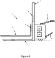
- Figure 1 schematically illustrates a fork-lift truck 1 according to an embodiment of the present disclosure, arranged to provide a constant maximum lifting height independent of the position of support arms 5.
- the fork-lift truck has a mast structure 2 and is thus able to fetch and leave a cargo on a shelf.
- a lifting device 4 is carried by the mast structure 2 and is movable along the mast structure 2.
- the fork-lift truck 1 comprises a tiller arm 8.
- the fork-lift truck 1 is controlled by an operator.
- the operator travels with the fork-lift truck, for example by means of a pivotable platform 3.
- the fork-lift truck 1 is preferably an electrically powered fork-lift truck 1 that has an electrical drive motor (not shown) and an electrical pump motor (not shown) for pumping hydraulic fluid.
- the lifting device 4 is preferably as seen in the Figures 1 , a pair of forks.
- the lifting device 4 can comprise more than two forks and fewer than two forks if desired.
- the fork-lift truck 1 further comprises support arms 5.
- the support arms 5 can be in an upright position or in a lowered position. In figure 1 the support arms 5 are in an upright position. When the support arms 5 are in a lowered position, as shown in figure 2 , it is possible to lower the lifting device 4 to the ground. In order to be able to lift a pallet, the support arms 5 have to be in the lowered position, or close to the ground, so it is possible to move the lifting device 4 close to the ground.
- the lifting device 4 has to be close to ground in order to make it possible to position the lifting device 4 in the slots of the pallet.
- the position of the support arms 5 is in an exemplary embodiment of the present disclosure senses by a support arm position sensor (not shown).
- the support arm position sensor gives information to the processor 110, shown in figure 4 , if the support arms 5 are in an upright position, in a lowered position or in a position in between.
- the lifting device 4 comprises an elongated element 6.
- the elongated element 6 according to one exemplary embodiment of the present disclosure comprises a magnetic or ferromagnetic material.
- the elongated element 6 can be position on many different positions on the lifting device 4.
- the elongated element 6 is preferably positioned close to the mast structure 2, so that the elongated element 6 can be sensed by a senor 7 on the mast structure 2, as will be described next.
- the sensor 7 is as described above positioned on the mast structure 2 and configured to sense a presence/absence of the elongated element 6.
- the fork-lift truck 1 is operative to stop an upward movement of the lifting device 4 when the senor 7 sense the presence of the elongated element 6 in a case where the support arms 5 are in an upright position.
- This enables the fork-lift truck 1 to always provide a constant maximum lifting height.
- the fork-lift truck is therefore, in this case operative to stop an upward movement of the lifting device 4 when the sensor 7 senses the presence of the elongated measuring 6 element.
- the position of the elongated element 6 on the lifting device 4 and the position of the sensor 7 on the mast structure 2 can according to embodiments of the present disclosure be changed. Depending on the position of the elongated element 6 on the lifting device 4 and the sensor 7 on the mast structure 2 different constant maximum lifting heights can be provided.
- the constant maximum lifting height is a maximum lifting height according to the International Standard for safety requirements of Industrial trucks, i.e. EN ISO 3691-1:2012.
- This constant maximum lifting height can be a maximum lifting height of 1800 mm from the floor.
- FIG 2 the support arms 5 of the fork-lift truck 1 is in a lowered position. As mentioned above, in this position it is possible to lower the lifting device 4 to a position close to the ground which makes it possible to position the lifting device 4 under e.g. a pallet.
- the fork-lift truck 1 is operative to ramp down the speed of the upward movement of the lifting device 4, when the sensor 7 sense the presence of the elongated element 6.
- the fork-lift truck 1 is also operative to stop the movement of the lifting device 4 when the lifting device 4 has moved upwards a predetermined distance wherein the sensor 7 sense the absence of the elongated element 6.
- the constant maximum lifting height also provided in this case.
- the mast structure 2 comprises several mast elements. These embodiments are not shown in the figures.
- the mast structure 2 comprises a first mast element, which carries the lifting device 4 and a second mast element, by which the first mast element is carried and along which the first mast element is movable.
- the mast structure 2 further comprises a third mast element, by which the second mast element is carried and along which the second mast element is movable.
- the mast structure 2 further comprises a fourth mast element, by which the third mast element is carried and along which the third mast element is movable.
- the fork-lift truck 1 is a pedestrian-controlled fork-lift truck 1 with protective side guards, not shown.
- the protective side guards protect the operator from falling of the fork-lift truck 1, when the protective side guards are in their protective position.
- the fork-lift truck is further arranged to provide the constant maximum lifting height when the protective side guards are in their protective position.
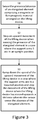
- Figure 3 is a flowchart schematically illustrating embodiments of method steps of operating a fork-lift truck 1 to provide a constant maximum lifting height independent of the position of support arms 5, wherein the fork-lift truck 1 comprises a lifting device 4, carried by a mast structure 2 and movable along the mast structure 2.
- a first step S1 the fork-lift truck 1 sense the presence/absence of an elongated element 6 comprising a magnetic or ferromagnetic material arranged on the lifting device 4.
- the fork-lift truck 1 stops an upward movement of the lifting device 4 when sensing the presence of the elongated element 6 in a case where the support arms 5 are in an upright position.
- the fork-lift truck 1 ramps down the speed of the upward movement of the lifting device 4 in a case where the support arms 5 are in a lowered position and stops the movement of the lifting device 4 when the lifting device 4 has moved upwards a predetermined distance wherein the sensor 7 sense the absence of the elongated element 6.
- the method of operating a fork-lift truck 1 to provide a constant maximum lifting height independent of the position of support arms 5, wherein the fork-lift truck 1 comprises a lifting device 4, can be performed by a fork-lift truck wherein the mast structure 2 comprises a first mast element, which carries the lifting device 4 and a second mast element, by which the first mast element is carried and along which the first mast element is movable 4.
- the method of operating a fork-lift truck 1 to provide a constant maximum lifting height independent of the position of support arms 5, wherein the fork-lift truck 1 comprises a lifting device 4, can be performed by a fork-lift truck, wherein the mast structure further comprises a third mast element, by which the second mast element is carried and along which the second mast element is movable.
- the method of operating a fork-lift truck 1 to provide a constant maximum lifting height independent of the position of support arms 5, wherein the fork-lift truck 1 comprises a lifting device 4, can be performed by a fork-lift truck, wherein the mast structure further comprises a fourth mast element, by which the third mast element is carried and along which the third mast element is movable.
- the fork-lift truck 1 is a pedestrian-controlled truck with protective side guards, and wherein the constant maximum lifting height is provided when the protective side guards are in their protective position.
- the constant maximum lifting height is a maximum lifting height according to the International Standard for safety requirements of Industrial trucks, i.e. EN ISO 3691-1:2012.
- the constant maximum lifting height is 1800 mm from the floor.
- the fork-lift truck 1 comprises a processor 110 and a memory 120, the memory 120 containing instructions executable by the processor 110.
- the processor 110 is a Central Processing Unit, CPU, microcontroller, Digital Signal Processor, DSP, or any other suitable type of processor capable of executing computer program code.
- the memory 120 is a Random Access Memory, RAM, a Read Only Memory, ROM, or a persistent storage, e.g. a single or combination of magnetic memory, optical memory, or solid state memory or even remotely mounted memory.
- the processor 110 and the memory 120 are here disclosed as being situated in the body of the fork-lift truck, but the processor 110 and the memory 120 can also preferably be located in the tiller arm 8 or the tiller head of the fork-lift truck 1.
- the processor 110 and the memory 120 is an external unit. This means that the fork-lift truck 1 must communicate with the processor 110 and the memory 120 by means of a communication device (not shown). This can preferably be a wire-less link.
- the communication device comprises in this embodiment an antenna.
- the disclosure further relates to a computer program, comprising computer readable code which, when run on the fork-lift truck 1 causes the fork-lift truck 1 to perform any of the aspects of the method described above.
- the computer program codes further causes the fork-lift truck 1 to stop an upward movement of the lifting device 4 when sensing the presence of the elongated element 6 in a case where the support arms 5 are in an upright position, or ramp down the speed of the upward movement of the lifting device 4 in a case where the support arms 5 are in a lowered position and stop the movement of the lifting device 4 when the lifting device 4 has moved upwards a predetermined distance wherein the sensor 7 sense the absence of the elongated element 6.
- the present disclosure also relates to a method of modifying a fork-lift truck, with support arms and a mast structure, such that the fork-lift truck is able to provide a constant maximum lifting height independent of the position of the support arms.
- the method comprising the steps of; providing a lifting device carried by the mast structure and movable along the mast structure with an elongated element comprising a magnetic or ferromagnetic material; providing the mast structure with sensor configured to sense a presence/absence of the elongated element; and providing a computer-readable storage medium in the fork-lift truck with a computer program which, when run in a processor of the fork-lift truck causes the fork-lift truck to perform any of the method as disclosed above.
- the functions or steps noted in the blocks can occur out of the order noted in the operational illustrations.
- two blocks shown in succession can in fact be executed substantially concurrently or the blocks can sometimes be executed in the reverse order, depending upon the functionality/acts involved.
- the functions or steps noted in the blocks can according to some aspects of the disclosure be executed continuously in a loop.
Description
- The present disclosure relates to a method of operating a fork-lift truck to provide a constant maximum lifting height independent of the position of its support arms, a fork-lift truck with support arms and a mast structure arranged to provide a constant maximum lifting height independent of the position of the support arms
- The disclosure also relates to a computer-readable storage medium, having stored thereon a computer program and a method of modifying a fork-lift truck, with support arms and a mast structure, such that the fork-lift truck is able to provide a constant maximum lifting height independent of the position of the support arms.
- When operating fork-lift trucks, the fork-lift truck is handled by an operator that either rides with the fork-lift truck or walks along the fork-lift truck. Generally pallets and/or goods are moved by the fork-lift truck by means of a lifting device, in general it is a pair of forks that enters in two slots of a pallet and then the forks are lifted and the pallet is lifted together with the forks. Then the fork-lift truck can travel a distance and the operator maneuvers the fork-lift truck to lower its forks and then place the pallet and leave this position without a load. The fork-lift truck is then driven by the operator without any pallet and/or goods, to a new location. During travel, the operator generally needs to raise/lift the load carrier/forks a small distance, in order to avoid unnecessary wear or damages to the forks by touching the ground.
- In general tiller arm trucks have a platform on which the operator can stand while operating the truck. Some fork-lift trucks are provided with protective side guards that protect the operator. The protective side guards can be in their protective position in which they protect the operator. The protective side guards can also be in their non-protective position in which the protective side guards do not protect the operator. On some fork-lift trucks there is a demand that the lifting device is limited to a maximum lifting height when the protective side guards are in their protective position. On fork-lift trucks which has movable support arms this means that the lifting device only can provide the maximum lifting height minus the lifting height of the support arms. This is a problem for operators that want to reach the maximum lifting height without having to raise the support arms.
- There is also another problem with fork-lift trucks that only can lift a maximum lifting height when the protective side guards are in in their protective position. When the lifting device is lifted with high speed and the lifting device has to stop at the maximum lifting height, the lifting device will not immediately stop since the hydraulic pump will not immediately stop and due to natural dynamics of the hydraulic fluid. If there is no load on the lifting device, the lifting device may continue e.g. 8 centimeters or more. If there is load on the lifting device, the lifting device will stop faster. However, this means that the maximum lifting height will vary depending on the load on the lifting device.
EP2251298 discloses an industrial truck comprises a lifting frame and a pair of support arms.EP2251298 does not disclose any solution to the problem with lifting height associated with support arms. - There is therefore a need for an improved fork-lift truck, which fork-lift truck solves or at least mitigates at least one of the above mentioned problems.
- It is an object of the present disclosure to provide embodiments solving the problem providing a fork-lift truck that can reach a maximum lifting height when the support arms are in a lowered position. Another object of the present disclosure is to provide a fork-lift truck where the maximum lifting height will not vary depending on the load on the lifting device.
- The disclosure presents a fork-lift truck with support arms and a mast structure, arranged to provide a constant maximum lifting height independent of the position of the support arms, wherein the fork-lift truck further comprises, a lifting device, carried by the mast structure and movable along the mast structure. The fork-lift truck further comprises an elongated element comprising a magnetic or ferromagnetic material arranged on the lifting device. A sensor arranged on the mast structure is configured to sense a presence/absence of the elongated element; wherein the fork-lift truck is operative to stop an upward movement of the lifting device when the senor sense the presence of the elongated element in a case where the support arms are in an upright position, to provide the constant maximum lifting height, or ramp down the speed of the upward movement of the lifting device in a case where the support arms are in a lowered position and stop the movement of the lifting device when the lifting device has moved upwards a predetermined distance wherein the sensor sense the absence of the elongated element, to provide the constant maximum lifting height.
- The present disclosure also relates to embodiments of a method of operating a fork-lift truck to provide a constant maximum lifting height independent of the position of the support arms, wherein the fork-lift truck comprises a lifting device, carried by a mast structure and movable along the mast structure. The method comprising the steps of: sensing the presence/absence of an elongated element comprising a magnetic or ferromagnetic material arranged on the lifting device. Stopping an upward movement of the lifting device when sensing the presence of the elongated element in a case where the support arms are in an upright position, or ramping down the speed of the upward movement of the lifting device in a case where the support arms are in a lowered position and stopping the movement of the lifting device when the lifting device has moved upwards a predetermined distance wherein the sensor sense the absence of the elongated element.
- The present disclosure also relates to embodiments of a method of modifying a fork-lift truck, with support arms and a mast structure, such that the fork-lift truck is able to provide a constant maximum lifting height independent of the position of the support arms, wherein the method comprising the steps of: providing a lifting device carried by the mast structure and movable along the mast structure with an elongated element comprising a magnetic or ferromagnetic material. Providing the mast structure with a sensor configured to sense a presence/absence of the elongated element, and providing a computer-readable storage medium in the fork-lift truck with a computer program which, when run in a processor of the fork-lift truck causes the fork-lift truck to perform the disclosed method.
- An advantage with embodiments of the present disclosure is that a maximum lifting height can be provided even if the support arms are in lowered position.
- Another advantage with embodiments of the present disclosure is that a fork-lift truck is provided where the maximum lifting height will not vary depending on the load on the lifting device.
- The present disclosure also presents a computer program, comprising computer readable code which, when run in a fork-lift truck causes the fork-lift truck to perform the disclosed method.
- The method of operating the fork-lift truck, and the computer program each display advantages corresponding to the advantages already described in relation to the method performed in the fork-lift truck.
- Further objects, features, and advantages of the present disclosure will appear from the following detailed description, wherein some aspects of the disclosure will be described in more detail with reference to the accompanying drawings, in which:
-
Figure 1 schematically illustrates a fork-lift truck according to an exemplary embodiment of the present disclosure. -
Figure 2 schematically illustrates a fork-lift truck according to an exemplary embodiment of the present disclosure. -
Figure 3 is a flow chart illustrating the proposed methods performed in the fork-lift truck. -
Figure 4 schematically illustrates a fork-lift truck according to an exemplary embodiment of the present disclosure. - Aspects of the present disclosure will be described more fully hereinafter with reference to the accompanying drawings. The methods and fork-lift truck disclosed herein can, however, be realized in many different forms and should not be construed as being limited to the aspects set forth herein. Like numbers in the drawings refer to like elements throughout.
- The general object or idea of embodiments of the present disclosure is to address at least one or some of the disadvantages described above as well as below. The various steps described below in connection with the figures should be primarily understood in a logical sense.
-
Figure 1 schematically illustrates a fork-lift truck 1 according to an embodiment of the present disclosure, arranged to provide a constant maximum lifting height independent of the position ofsupport arms 5. The fork-lift truck has amast structure 2 and is thus able to fetch and leave a cargo on a shelf. Alifting device 4 is carried by themast structure 2 and is movable along themast structure 2. According to exemplary embodiments of the present disclosure the fork-lift truck 1 comprises atiller arm 8. - The fork-
lift truck 1 is controlled by an operator. The operator travels with the fork-lift truck, for example by means of apivotable platform 3. The fork-lift truck 1 is preferably an electrically powered fork-lift truck 1 that has an electrical drive motor (not shown) and an electrical pump motor (not shown) for pumping hydraulic fluid. - The
lifting device 4 is preferably as seen in theFigures 1 , a pair of forks. Thelifting device 4 can comprise more than two forks and fewer than two forks if desired. The fork-lift truck 1 further comprisessupport arms 5. Thesupport arms 5 can be in an upright position or in a lowered position. Infigure 1 thesupport arms 5 are in an upright position. When thesupport arms 5 are in a lowered position, as shown infigure 2 , it is possible to lower thelifting device 4 to the ground. In order to be able to lift a pallet, thesupport arms 5 have to be in the lowered position, or close to the ground, so it is possible to move thelifting device 4 close to the ground. Thelifting device 4 has to be close to ground in order to make it possible to position thelifting device 4 in the slots of the pallet. - The position of the
support arms 5 is in an exemplary embodiment of the present disclosure senses by a support arm position sensor (not shown). The support arm position sensor gives information to theprocessor 110, shown infigure 4 , if thesupport arms 5 are in an upright position, in a lowered position or in a position in between. - The
lifting device 4 according to an exemplary embodiment of the present disclosure comprises anelongated element 6. Theelongated element 6 according to one exemplary embodiment of the present disclosure comprises a magnetic or ferromagnetic material. Theelongated element 6 can be position on many different positions on thelifting device 4. Theelongated element 6 is preferably positioned close to themast structure 2, so that theelongated element 6 can be sensed by asenor 7 on themast structure 2, as will be described next. Thesensor 7 is as described above positioned on themast structure 2 and configured to sense a presence/absence of theelongated element 6. - According to embodiments of the present disclosure the fork-
lift truck 1 is operative to stop an upward movement of thelifting device 4 when thesenor 7 sense the presence of theelongated element 6 in a case where thesupport arms 5 are in an upright position. This enables the fork-lift truck 1 to always provide a constant maximum lifting height. When thesupport arms 5 are in an upright position thelifting device 4 and themast structure 2 are in their respective highest position. The fork-lift truck is therefore, in this case operative to stop an upward movement of thelifting device 4 when thesensor 7 senses the presence of the elongated measuring 6 element. The position of theelongated element 6 on thelifting device 4 and the position of thesensor 7 on themast structure 2 can according to embodiments of the present disclosure be changed. Depending on the position of theelongated element 6 on thelifting device 4 and thesensor 7 on themast structure 2 different constant maximum lifting heights can be provided. - According to one exemplary embodiment of the present disclosure the constant maximum lifting height is a maximum lifting height according to the International Standard for safety requirements of Industrial trucks, i.e. EN ISO 3691-1:2012. This constant maximum lifting height can be a maximum lifting height of 1800 mm from the floor.
- Now turn to
figure 2 . Infigure 2 thesupport arms 5 of the fork-lift truck 1 is in a lowered position. As mentioned above, in this position it is possible to lower thelifting device 4 to a position close to the ground which makes it possible to position thelifting device 4 under e.g. a pallet. When thesupport arms 5 are in a lowered position the fork-lift truck 1 is operative to ramp down the speed of the upward movement of thelifting device 4, when thesensor 7 sense the presence of theelongated element 6. In this case the fork-lift truck 1 is also operative to stop the movement of thelifting device 4 when thelifting device 4 has moved upwards a predetermined distance wherein thesensor 7 sense the absence of theelongated element 6. Thus is the constant maximum lifting height also provided in this case. - Now will embodiments of the present disclosure be described in which the
mast structure 2 comprises several mast elements. These embodiments are not shown in the figures. - In one exemplary embodiment of the present disclosure the
mast structure 2 comprises a first mast element, which carries thelifting device 4 and a second mast element, by which the first mast element is carried and along which the first mast element is movable. - In yet another exemplary embodiment of the present disclosure the
mast structure 2 further comprises a third mast element, by which the second mast element is carried and along which the second mast element is movable. - In a further exemplary embodiment of the present disclosure the
mast structure 2 further comprises a fourth mast element, by which the third mast element is carried and along which the third mast element is movable. - The fork-
lift truck 1 according to exemplary embodiments of the present disclosure is a pedestrian-controlled fork-lift truck 1 with protective side guards, not shown. The protective side guards protect the operator from falling of the fork-lift truck 1, when the protective side guards are in their protective position. According to one exemplary embodiment of the present disclosure the fork-lift truck is further arranged to provide the constant maximum lifting height when the protective side guards are in their protective position. -
Figure 3 is a flowchart schematically illustrating embodiments of method steps of operating a fork-lift truck 1 to provide a constant maximum lifting height independent of the position ofsupport arms 5, wherein the fork-lift truck 1 comprises alifting device 4, carried by amast structure 2 and movable along themast structure 2. - In a first step S1, the fork-
lift truck 1 sense the presence/absence of anelongated element 6 comprising a magnetic or ferromagnetic material arranged on thelifting device 4. - In a next step S2, the fork-
lift truck 1 stops an upward movement of thelifting device 4 when sensing the presence of theelongated element 6 in a case where thesupport arms 5 are in an upright position. - In a further step S3, the fork-
lift truck 1 ramps down the speed of the upward movement of thelifting device 4 in a case where thesupport arms 5 are in a lowered position and stops the movement of thelifting device 4 when thelifting device 4 has moved upwards a predetermined distance wherein thesensor 7 sense the absence of theelongated element 6. - The method of operating a fork-
lift truck 1 to provide a constant maximum lifting height independent of the position ofsupport arms 5, wherein the fork-lift truck 1 comprises alifting device 4, can be performed by a fork-lift truck wherein themast structure 2 comprises a first mast element, which carries thelifting device 4 and a second mast element, by which the first mast element is carried and along which the first mast element is movable 4. - According to another embodiment of the present disclosure, the method of operating a fork-
lift truck 1 to provide a constant maximum lifting height independent of the position ofsupport arms 5, wherein the fork-lift truck 1 comprises alifting device 4, can be performed by a fork-lift truck, wherein the mast structure further comprises a third mast element, by which the second mast element is carried and along which the second mast element is movable. - In a yet another embodiment of the present disclosure, the method of operating a fork-
lift truck 1 to provide a constant maximum lifting height independent of the position ofsupport arms 5, wherein the fork-lift truck 1 comprises alifting device 4, can be performed by a fork-lift truck, wherein the mast structure further comprises a fourth mast element, by which the third mast element is carried and along which the third mast element is movable. - The fork-
lift truck 1 according to an embodiment of the present disclosure is a pedestrian-controlled truck with protective side guards, and wherein the constant maximum lifting height is provided when the protective side guards are in their protective position. - According to an exemplary embodiment of the method of operating a fork-
lift truck 1 to provide a constant maximum lifting height according to the present disclosure, the constant maximum lifting height is a maximum lifting height according to the International Standard for safety requirements of Industrial trucks, i.e. EN ISO 3691-1:2012. - According to another exemplary embodiment of the method of operating a fork-
lift truck 1 to provide a constant maximum lifting height according to the present disclosure, the constant maximum lifting height is 1800 mm from the floor. - Turning now to
figure 4 , a schematic diagram is disclosed illustrating an exemplary embodiment of a fork-lift truck 1 with support arms and a mast structure, arranged to provide a constant maximum lifting height independent of the position of the support arms. The fork-lift truck 1 comprises aprocessor 110 and amemory 120, thememory 120 containing instructions executable by theprocessor 110. Theprocessor 110 is a Central Processing Unit, CPU, microcontroller, Digital Signal Processor, DSP, or any other suitable type of processor capable of executing computer program code. Thememory 120 is a Random Access Memory, RAM, a Read Only Memory, ROM, or a persistent storage, e.g. a single or combination of magnetic memory, optical memory, or solid state memory or even remotely mounted memory. - The
processor 110 and thememory 120 are here disclosed as being situated in the body of the fork-lift truck, but theprocessor 110 and thememory 120 can also preferably be located in thetiller arm 8 or the tiller head of the fork-lift truck 1. In another embodiment of the present disclosure, theprocessor 110 and thememory 120 is an external unit. This means that the fork-lift truck 1 must communicate with theprocessor 110 and thememory 120 by means of a communication device (not shown). This can preferably be a wire-less link. The communication device comprises in this embodiment an antenna. - According to one aspect, the disclosure further relates to a computer program, comprising computer readable code which, when run on the fork-
lift truck 1 causes the fork-lift truck 1 to perform any of the aspects of the method described above. - When the above-mentioned computer program code is run in the
processor 110 of the fork-lift truck 1 it causes the fork-lift truck 1 to sense the presence/absence of anelongated element 6 comprising a magnetic or ferromagnetic material arranged on thelifting device 4. - The computer program codes further causes the fork-
lift truck 1 to stop an upward movement of thelifting device 4 when sensing the presence of theelongated element 6 in a case where thesupport arms 5 are in an upright position, or ramp down the speed of the upward movement of thelifting device 4 in a case where thesupport arms 5 are in a lowered position and stop the movement of thelifting device 4 when thelifting device 4 has moved upwards a predetermined distance wherein thesensor 7 sense the absence of theelongated element 6. - The present disclosure also relates to a method of modifying a fork-lift truck, with support arms and a mast structure, such that the fork-lift truck is able to provide a constant maximum lifting height independent of the position of the support arms. The method comprising the steps of; providing a lifting device carried by the mast structure and movable along the mast structure with an elongated element comprising a magnetic or ferromagnetic material; providing the mast structure with sensor configured to sense a presence/absence of the elongated element; and providing a computer-readable storage medium in the fork-lift truck with a computer program which, when run in a processor of the fork-lift truck causes the fork-lift truck to perform any of the method as disclosed above.
- Aspects of the disclosure are described with reference to the drawings, e.g., block diagrams and/or flowcharts. It is understood that several entities in the drawings, e.g., blocks of the block diagrams, and also combinations of entities in the drawings, can be implemented by computer program instructions, which instructions can be stored in a computer-readable memory, and also loaded onto a computer or other programmable data processing apparatus. Such computer program instructions can be provided to a processor of a general purpose computer, a special purpose computer and/or other programmable data processing apparatus to produce a machine, such that the instructions, which execute via the processor of the computer and/or other programmable data processing apparatus, create means for implementing the functions/acts specified in the block diagrams and/or flowchart block or blocks.
- In some implementations and according to some aspects of the disclosure, the functions or steps noted in the blocks can occur out of the order noted in the operational illustrations. For example, two blocks shown in succession can in fact be executed substantially concurrently or the blocks can sometimes be executed in the reverse order, depending upon the functionality/acts involved. Also, the functions or steps noted in the blocks can according to some aspects of the disclosure be executed continuously in a loop.
Claims (12)
- A fork-lift truck (1) with support arms (5) and a mast structure (2), arranged to provide a constant maximum lifting height independent of the position of the support arms (5), wherein said fork-lift truck (1) further comprises:- a lifting device (4), carried by the mast structure (2) and movable along the mast structure (2); characterized by:- an elongated element (6) comprising a magnetic or ferromagnetic material arranged on the lifting device (4);- a sensor (7) arranged on the mast structure (2) configured to sense a presence/absence of the elongated element (6); wherein said fork-lift truck (1) is operative to stop an upward movement of the lifting device (4) when the senor (7) sense the presence of the elongated element (6) in a case where the support arms (5) are in an upright position, to provide the constant maximum lifting height, or ramp down the speed of the upward movement of the lifting device (4) in a case where the support arms (5) are in a lowered position and stop the movement of the lifting device (4) when the lifting device (4) has moved upwards a predetermined distance wherein the sensor (7) sense the absence of the elongated element (6), to provide the constant maximum lifting height.
- A fork-lift truck (1) according to claim 1, wherein the mast structure (2) comprises a first mast element, which carries the lifting device (4) and a second mast element, by which the first mast element is carried and along which the first mast element is movable.
- A fork-lift truck (1) according to claim 2, wherein the mast structure (2) further comprises a third mast element, by which the second mast element is carried and along which the second mast element is movable.
- A fork-lift truck (1) according to any of claims 1 to 3, wherein the fork-lift truck (1) is a pedestrian-controlled fork-lift truck with protective side guards, and wherein the fork-lift truck is further arranged to provide the constant maximum lifting height when the protective side guards is in their protective position
- A fork-lift truck according to any of claims 1 to 4, wherein the constant maximum lifting height is a maximum lifting height according to the International Standard for safety requirements of Industrial trucks.
- Method of operating a fork-lift truck (1) to provide a constant maximum lifting height independent of the position of support arms 5, wherein the fork-lift truck (1) comprises a lifting device (4), carried by a mast structure (2) and movable along the mast structure (2), the method is characterized by the steps of:- sensing the presence/absence of an elongated element (6) comprising a magnetic or ferromagnetic material arranged on the lifting device (4);- stopping an upward movement of the lifting device (4) when sensing the presence of the elongated element (6) in a case where the support arms (5) are in an upright position, or- ramping down the speed of the upward movement of the lifting device (4) in a case where the support arms (5) are in a lowered position and stopping the movement of the lifting device (4) when the lifting device (4) has moved upwards a predetermined distance wherein the sensor (7) sense the absence of the elongated element (6).
- Method of operating a fork-lift truck (1) according to claim 6, wherein the mast structure (2) comprises a first mast element, which carries the lifting device (4) and a second mast element, by which the first mast element is carried and along which the first mast element is movable.
- Method of operating a fork-lift truck (1) according to claim 7, wherein the mast structure (2) further comprises a third mast element, by which the second mast element is carried and along which the second mast element is movable.
- Method of operating a fork-lift truck (1) according to any of claims 6 to 8, wherein the fork-lift truck (1) is a pedestrian-controlled truck with protective side guards, and wherein the constant maximum lifting height is provided when the protective side guards is in their protective position
- Method of operating a fork-lift truck according to any of claims 6 to 9, wherein the constant maximum lifting height is a maximum lifting height according to the International Standard for safety requirements of Industrial trucks.
- A computer-readable storage medium, having stored there on a computer program which, when run in a processor of a fork-lift truck (1), causes the fork-lift truck to perform the method as claimed in any of claims 6-10.
- Method of modifying a fork-lift truck 1, with support arms (5) and a mast structure (2), such that the fork-lift truck (1) is able to provide a constant maximum lifting height independent of the position of the support arms (5), wherein the method comprising the steps of:- providing a lifting device (4) carried by the mast structure (2) and movable along the mast structure (2) with an elongated element (6) comprising a magnetic or ferromagnetic material;- providing the mast structure (2) with a sensor (7) configured to sense a presence/absence of the elongated element (6); and- providing a computer-readable storage medium in the fork-lift truck with a computer program which, when run in a processor of the fork-lift truck causes the fork-lift truck to perform the method as claimed in any of claims 6-10.
Priority Applications (1)
| Application Number | Priority Date | Filing Date | Title |
|---|---|---|---|
| EP14172090.4A EP2955149B1 (en) | 2014-06-12 | 2014-06-12 | Method of operating a fork-lift truck, a fork-lift truck, a computer program product, and a method of modifying a fork-lift truck |
Applications Claiming Priority (1)
| Application Number | Priority Date | Filing Date | Title |
|---|---|---|---|
| EP14172090.4A EP2955149B1 (en) | 2014-06-12 | 2014-06-12 | Method of operating a fork-lift truck, a fork-lift truck, a computer program product, and a method of modifying a fork-lift truck |
Publications (2)
| Publication Number | Publication Date |
|---|---|
| EP2955149A1 EP2955149A1 (en) | 2015-12-16 |
| EP2955149B1 true EP2955149B1 (en) | 2017-12-20 |
Family
ID=50942111
Family Applications (1)
| Application Number | Title | Priority Date | Filing Date |
|---|---|---|---|
| EP14172090.4A Active EP2955149B1 (en) | 2014-06-12 | 2014-06-12 | Method of operating a fork-lift truck, a fork-lift truck, a computer program product, and a method of modifying a fork-lift truck |
Country Status (1)
| Country | Link |
|---|---|
| EP (1) | EP2955149B1 (en) |
Families Citing this family (1)
| Publication number | Priority date | Publication date | Assignee | Title |
|---|---|---|---|---|
| EP3208228B1 (en) * | 2016-02-19 | 2018-12-05 | Toyota Material Handling Manufacturing Sweden AB | A lift-truck with automated height adjustment of load engagement means |
Family Cites Families (4)
| Publication number | Priority date | Publication date | Assignee | Title |
|---|---|---|---|---|
| CN101610968B (en) * | 2007-01-08 | 2013-05-08 | 比沙门工业股份有限公司 | Lift for skids and pallets |
| DE102009020947A1 (en) * | 2009-05-12 | 2010-11-18 | Jungheinrich Aktiengesellschaft | Industrial truck with a pair of radar arms |
| DE102010022374A1 (en) * | 2010-05-27 | 2011-12-01 | Jungheinrich Aktiengesellschaft | Method for providing information about a current lifting height and suitable industrial truck |
| DE102011100914A1 (en) * | 2011-04-29 | 2012-10-31 | Jungheinrich Aktiengesellschaft | Truck with a limit switch system |
-
2014
- 2014-06-12 EP EP14172090.4A patent/EP2955149B1/en active Active
Non-Patent Citations (1)
| Title |
|---|
| None * |
Also Published As
| Publication number | Publication date |
|---|---|
| EP2955149A1 (en) | 2015-12-16 |
Similar Documents
| Publication | Publication Date | Title |
|---|---|---|
| US9950877B2 (en) | Product shipment loading and unloading systems and methods | |
| EP2447203B1 (en) | Industrial truck, method and computer program for controlling an industrial truck | |
| JP6268307B2 (en) | Side shift limiter | |
| CN106604886A (en) | Lift truck with optical load sensing structure | |
| US20080044262A1 (en) | Article storage facility and operation method thereof | |
| EP2527288B1 (en) | Fork lift truck with automatic lift height control | |
| KR101462527B1 (en) | Automated guided vehicles | |
| KR101377662B1 (en) | Double loading type unmanned forklift | |
| US20150225218A1 (en) | Method Of Operating A Fork-Lift Truck, Computer Program Product, And A Fork-Lift Truck | |
| AU2019202422A1 (en) | Multi-position load detection systems and methods | |
| JP4947359B2 (en) | Article conveying device | |
| EP2955149B1 (en) | Method of operating a fork-lift truck, a fork-lift truck, a computer program product, and a method of modifying a fork-lift truck | |
| KR101666638B1 (en) | Unmanned forklift device using PWM signal | |
| JP2006219297A (en) | Article conveying apparatus | |
| JP7096429B2 (en) | Forklift for handling pneumatic tires with transponders | |
| WO2022143140A1 (en) | Pallet fork collision processing method and apparatus, and robot, device, medium and product | |
| KR200467883Y1 (en) | Distribution transfer system | |
| JP2005187117A (en) | Unmanned forklift and control method therefor | |
| JP2023541564A (en) | A method for managing a warehouse containing pneumatic tires equipped with transponders and arranged in vertical stacks | |
| CN110914190B (en) | Clamping device for a fork lift truck and fork lift truck having such a clamping device | |
| EP3235776B1 (en) | Fork-lift truck | |
| KR101415975B1 (en) | Automatic fork control apparatus and method for forklift | |
| JP5348480B2 (en) | Goods transport equipment | |
| CN105383882A (en) | Full-automatic material conveying lifting table | |
| KR20230081607A (en) | Automated warehouse system and automated warehouse control method |
Legal Events
| Date | Code | Title | Description |
|---|---|---|---|
| PUAI | Public reference made under article 153(3) epc to a published international application that has entered the european phase |
Free format text: ORIGINAL CODE: 0009012 |
|
| AK | Designated contracting states |
Kind code of ref document: A1 Designated state(s): AL AT BE BG CH CY CZ DE DK EE ES FI FR GB GR HR HU IE IS IT LI LT LU LV MC MK MT NL NO PL PT RO RS SE SI SK SM TR |
|
| AX | Request for extension of the european patent |
Extension state: BA ME |
|
| 17P | Request for examination filed |
Effective date: 20160518 |
|
| RBV | Designated contracting states (corrected) |
Designated state(s): AL AT BE BG CH CY CZ DE DK EE ES FI FR GB GR HR HU IE IS IT LI LT LU LV MC MK MT NL NO PL PT RO RS SE SI SK SM TR |
|
| RAP1 | Party data changed (applicant data changed or rights of an application transferred) |
Owner name: TOYOTA MATERIAL HANDLING MANUFACTURING SWEDEN AB |
|
| GRAP | Despatch of communication of intention to grant a patent |
Free format text: ORIGINAL CODE: EPIDOSNIGR1 |
|
| STAA | Information on the status of an ep patent application or granted ep patent |
Free format text: STATUS: GRANT OF PATENT IS INTENDED |
|
| INTG | Intention to grant announced |
Effective date: 20170719 |
|
| GRAS | Grant fee paid |
Free format text: ORIGINAL CODE: EPIDOSNIGR3 |
|
| GRAA | (expected) grant |
Free format text: ORIGINAL CODE: 0009210 |
|
| STAA | Information on the status of an ep patent application or granted ep patent |
Free format text: STATUS: THE PATENT HAS BEEN GRANTED |
|
| AK | Designated contracting states |
Kind code of ref document: B1 Designated state(s): AL AT BE BG CH CY CZ DE DK EE ES FI FR GB GR HR HU IE IS IT LI LT LU LV MC MK MT NL NO PL PT RO RS SE SI SK SM TR |
|
| REG | Reference to a national code |
Ref country code: GB Ref legal event code: FG4D |
|
| REG | Reference to a national code |
Ref country code: CH Ref legal event code: EP |
|
| REG | Reference to a national code |
Ref country code: IE Ref legal event code: FG4D |
|
| REG | Reference to a national code |
Ref country code: AT Ref legal event code: REF Ref document number: 956173 Country of ref document: AT Kind code of ref document: T Effective date: 20180115 |
|
| REG | Reference to a national code |
Ref country code: DE Ref legal event code: R096 Ref document number: 602014018657 Country of ref document: DE |
|
| REG | Reference to a national code |
Ref country code: SE Ref legal event code: TRGR |
|
| REG | Reference to a national code |
Ref country code: NL Ref legal event code: MP Effective date: 20171220 |
|
| PG25 | Lapsed in a contracting state [announced via postgrant information from national office to epo] |
Ref country code: LT Free format text: LAPSE BECAUSE OF FAILURE TO SUBMIT A TRANSLATION OF THE DESCRIPTION OR TO PAY THE FEE WITHIN THE PRESCRIBED TIME-LIMIT Effective date: 20171220 Ref country code: NO Free format text: LAPSE BECAUSE OF FAILURE TO SUBMIT A TRANSLATION OF THE DESCRIPTION OR TO PAY THE FEE WITHIN THE PRESCRIBED TIME-LIMIT Effective date: 20180320 Ref country code: FI Free format text: LAPSE BECAUSE OF FAILURE TO SUBMIT A TRANSLATION OF THE DESCRIPTION OR TO PAY THE FEE WITHIN THE PRESCRIBED TIME-LIMIT Effective date: 20171220 |
|
| REG | Reference to a national code |
Ref country code: LT Ref legal event code: MG4D |
|
| REG | Reference to a national code |
Ref country code: AT Ref legal event code: MK05 Ref document number: 956173 Country of ref document: AT Kind code of ref document: T Effective date: 20171220 |
|
| PG25 | Lapsed in a contracting state [announced via postgrant information from national office to epo] |
Ref country code: LV Free format text: LAPSE BECAUSE OF FAILURE TO SUBMIT A TRANSLATION OF THE DESCRIPTION OR TO PAY THE FEE WITHIN THE PRESCRIBED TIME-LIMIT Effective date: 20171220 Ref country code: RS Free format text: LAPSE BECAUSE OF FAILURE TO SUBMIT A TRANSLATION OF THE DESCRIPTION OR TO PAY THE FEE WITHIN THE PRESCRIBED TIME-LIMIT Effective date: 20171220 Ref country code: HR Free format text: LAPSE BECAUSE OF FAILURE TO SUBMIT A TRANSLATION OF THE DESCRIPTION OR TO PAY THE FEE WITHIN THE PRESCRIBED TIME-LIMIT Effective date: 20171220 Ref country code: GR Free format text: LAPSE BECAUSE OF FAILURE TO SUBMIT A TRANSLATION OF THE DESCRIPTION OR TO PAY THE FEE WITHIN THE PRESCRIBED TIME-LIMIT Effective date: 20180321 Ref country code: BG Free format text: LAPSE BECAUSE OF FAILURE TO SUBMIT A TRANSLATION OF THE DESCRIPTION OR TO PAY THE FEE WITHIN THE PRESCRIBED TIME-LIMIT Effective date: 20180320 |
|
| REG | Reference to a national code |
Ref country code: FR Ref legal event code: PLFP Year of fee payment: 5 |
|
| PG25 | Lapsed in a contracting state [announced via postgrant information from national office to epo] |
Ref country code: NL Free format text: LAPSE BECAUSE OF FAILURE TO SUBMIT A TRANSLATION OF THE DESCRIPTION OR TO PAY THE FEE WITHIN THE PRESCRIBED TIME-LIMIT Effective date: 20171220 |
|
| PG25 | Lapsed in a contracting state [announced via postgrant information from national office to epo] |
Ref country code: EE Free format text: LAPSE BECAUSE OF FAILURE TO SUBMIT A TRANSLATION OF THE DESCRIPTION OR TO PAY THE FEE WITHIN THE PRESCRIBED TIME-LIMIT Effective date: 20171220 Ref country code: CY Free format text: LAPSE BECAUSE OF FAILURE TO SUBMIT A TRANSLATION OF THE DESCRIPTION OR TO PAY THE FEE WITHIN THE PRESCRIBED TIME-LIMIT Effective date: 20171220 Ref country code: SK Free format text: LAPSE BECAUSE OF FAILURE TO SUBMIT A TRANSLATION OF THE DESCRIPTION OR TO PAY THE FEE WITHIN THE PRESCRIBED TIME-LIMIT Effective date: 20171220 Ref country code: CZ Free format text: LAPSE BECAUSE OF FAILURE TO SUBMIT A TRANSLATION OF THE DESCRIPTION OR TO PAY THE FEE WITHIN THE PRESCRIBED TIME-LIMIT Effective date: 20171220 Ref country code: ES Free format text: LAPSE BECAUSE OF FAILURE TO SUBMIT A TRANSLATION OF THE DESCRIPTION OR TO PAY THE FEE WITHIN THE PRESCRIBED TIME-LIMIT Effective date: 20171220 |
|
| PG25 | Lapsed in a contracting state [announced via postgrant information from national office to epo] |
Ref country code: PL Free format text: LAPSE BECAUSE OF FAILURE TO SUBMIT A TRANSLATION OF THE DESCRIPTION OR TO PAY THE FEE WITHIN THE PRESCRIBED TIME-LIMIT Effective date: 20171220 Ref country code: SM Free format text: LAPSE BECAUSE OF FAILURE TO SUBMIT A TRANSLATION OF THE DESCRIPTION OR TO PAY THE FEE WITHIN THE PRESCRIBED TIME-LIMIT Effective date: 20171220 Ref country code: AT Free format text: LAPSE BECAUSE OF FAILURE TO SUBMIT A TRANSLATION OF THE DESCRIPTION OR TO PAY THE FEE WITHIN THE PRESCRIBED TIME-LIMIT Effective date: 20171220 Ref country code: IT Free format text: LAPSE BECAUSE OF FAILURE TO SUBMIT A TRANSLATION OF THE DESCRIPTION OR TO PAY THE FEE WITHIN THE PRESCRIBED TIME-LIMIT Effective date: 20171220 Ref country code: RO Free format text: LAPSE BECAUSE OF FAILURE TO SUBMIT A TRANSLATION OF THE DESCRIPTION OR TO PAY THE FEE WITHIN THE PRESCRIBED TIME-LIMIT Effective date: 20171220 Ref country code: IS Free format text: LAPSE BECAUSE OF FAILURE TO SUBMIT A TRANSLATION OF THE DESCRIPTION OR TO PAY THE FEE WITHIN THE PRESCRIBED TIME-LIMIT Effective date: 20180420 |
|
| REG | Reference to a national code |
Ref country code: DE Ref legal event code: R097 Ref document number: 602014018657 Country of ref document: DE |
|
| PLBE | No opposition filed within time limit |
Free format text: ORIGINAL CODE: 0009261 |
|
| STAA | Information on the status of an ep patent application or granted ep patent |
Free format text: STATUS: NO OPPOSITION FILED WITHIN TIME LIMIT |
|
| 26N | No opposition filed |
Effective date: 20180921 |
|
| PG25 | Lapsed in a contracting state [announced via postgrant information from national office to epo] |
Ref country code: DK Free format text: LAPSE BECAUSE OF FAILURE TO SUBMIT A TRANSLATION OF THE DESCRIPTION OR TO PAY THE FEE WITHIN THE PRESCRIBED TIME-LIMIT Effective date: 20171220 |
|
| REG | Reference to a national code |
Ref country code: CH Ref legal event code: PL |
|
| PG25 | Lapsed in a contracting state [announced via postgrant information from national office to epo] |
Ref country code: SI Free format text: LAPSE BECAUSE OF FAILURE TO SUBMIT A TRANSLATION OF THE DESCRIPTION OR TO PAY THE FEE WITHIN THE PRESCRIBED TIME-LIMIT Effective date: 20171220 |
|
| REG | Reference to a national code |
Ref country code: BE Ref legal event code: MM Effective date: 20180630 |
|
| REG | Reference to a national code |
Ref country code: IE Ref legal event code: MM4A |
|
| PG25 | Lapsed in a contracting state [announced via postgrant information from national office to epo] |
Ref country code: MC Free format text: LAPSE BECAUSE OF FAILURE TO SUBMIT A TRANSLATION OF THE DESCRIPTION OR TO PAY THE FEE WITHIN THE PRESCRIBED TIME-LIMIT Effective date: 20171220 Ref country code: LU Free format text: LAPSE BECAUSE OF NON-PAYMENT OF DUE FEES Effective date: 20180612 |
|
| PG25 | Lapsed in a contracting state [announced via postgrant information from national office to epo] |
Ref country code: CH Free format text: LAPSE BECAUSE OF NON-PAYMENT OF DUE FEES Effective date: 20180630 Ref country code: IE Free format text: LAPSE BECAUSE OF NON-PAYMENT OF DUE FEES Effective date: 20180612 Ref country code: LI Free format text: LAPSE BECAUSE OF NON-PAYMENT OF DUE FEES Effective date: 20180630 |
|
| PG25 | Lapsed in a contracting state [announced via postgrant information from national office to epo] |
Ref country code: BE Free format text: LAPSE BECAUSE OF NON-PAYMENT OF DUE FEES Effective date: 20180630 |
|
| PG25 | Lapsed in a contracting state [announced via postgrant information from national office to epo] |
Ref country code: MT Free format text: LAPSE BECAUSE OF NON-PAYMENT OF DUE FEES Effective date: 20180612 |
|
| PG25 | Lapsed in a contracting state [announced via postgrant information from national office to epo] |
Ref country code: TR Free format text: LAPSE BECAUSE OF FAILURE TO SUBMIT A TRANSLATION OF THE DESCRIPTION OR TO PAY THE FEE WITHIN THE PRESCRIBED TIME-LIMIT Effective date: 20171220 |
|
| PG25 | Lapsed in a contracting state [announced via postgrant information from national office to epo] |
Ref country code: PT Free format text: LAPSE BECAUSE OF FAILURE TO SUBMIT A TRANSLATION OF THE DESCRIPTION OR TO PAY THE FEE WITHIN THE PRESCRIBED TIME-LIMIT Effective date: 20171220 |
|
| PG25 | Lapsed in a contracting state [announced via postgrant information from national office to epo] |
Ref country code: MK Free format text: LAPSE BECAUSE OF NON-PAYMENT OF DUE FEES Effective date: 20171220 Ref country code: HU Free format text: LAPSE BECAUSE OF FAILURE TO SUBMIT A TRANSLATION OF THE DESCRIPTION OR TO PAY THE FEE WITHIN THE PRESCRIBED TIME-LIMIT; INVALID AB INITIO Effective date: 20140612 |
|
| PG25 | Lapsed in a contracting state [announced via postgrant information from national office to epo] |
Ref country code: AL Free format text: LAPSE BECAUSE OF FAILURE TO SUBMIT A TRANSLATION OF THE DESCRIPTION OR TO PAY THE FEE WITHIN THE PRESCRIBED TIME-LIMIT Effective date: 20171220 |
|
| P01 | Opt-out of the competence of the unified patent court (upc) registered |
Effective date: 20230526 |
|
| PGFP | Annual fee paid to national office [announced via postgrant information from national office to epo] |
Ref country code: FR Payment date: 20230622 Year of fee payment: 10 Ref country code: DE Payment date: 20230627 Year of fee payment: 10 |
|
| PGFP | Annual fee paid to national office [announced via postgrant information from national office to epo] |
Ref country code: SE Payment date: 20230627 Year of fee payment: 10 |
|
| PGFP | Annual fee paid to national office [announced via postgrant information from national office to epo] |
Ref country code: GB Payment date: 20230620 Year of fee payment: 10 |