EP2457797A1 - Vehicle air-conditioning control method - Google Patents
Vehicle air-conditioning control method Download PDFInfo
- Publication number
- EP2457797A1 EP2457797A1 EP09847554A EP09847554A EP2457797A1 EP 2457797 A1 EP2457797 A1 EP 2457797A1 EP 09847554 A EP09847554 A EP 09847554A EP 09847554 A EP09847554 A EP 09847554A EP 2457797 A1 EP2457797 A1 EP 2457797A1
- Authority
- EP
- European Patent Office
- Prior art keywords
- vehicle
- air
- conditioning
- conditioning control
- temperature
- Prior art date
- Legal status (The legal status is an assumption and is not a legal conclusion. Google has not performed a legal analysis and makes no representation as to the accuracy of the status listed.)
- Granted
Links
- 238000004378 air conditioning Methods 0.000 title claims abstract description 139
- 238000000034 method Methods 0.000 title claims abstract description 41
- 238000009423 ventilation Methods 0.000 claims description 9
- 238000012937 correction Methods 0.000 description 5
- 230000005540 biological transmission Effects 0.000 description 4
- 238000010586 diagram Methods 0.000 description 4
- 238000005259 measurement Methods 0.000 description 4
- 238000012986 modification Methods 0.000 description 2
- 230000004048 modification Effects 0.000 description 2
- 238000013459 approach Methods 0.000 description 1
- 238000012545 processing Methods 0.000 description 1
Images


Classifications
-
- B—PERFORMING OPERATIONS; TRANSPORTING
- B61—RAILWAYS
- B61D—BODY DETAILS OR KINDS OF RAILWAY VEHICLES
- B61D27/00—Heating, cooling, ventilating, or air-conditioning
- B61D27/0072—Means for cooling only
Definitions
- the present invention relates to a vehicle air-conditioning control method for controlling air-conditioning of the interior of a railway vehicle.
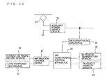
- a vehicle air-conditioning control method include that shown in FIG. 10 . That is, in the vehicle air-conditioning control method of the related art, as shown in FIG. 10 , electric power input from a pantograph 23 is supplied to an auxiliary power-supply device 24, whereby an air-conditioning power is generated and is supplied to an air-conditioning apparatus 25.
- the air-conditioning apparatus 25 uses an air-conditioning control apparatus 26 so as to control the number of operating units, the operating frequency, and the running time of air-conditioning compressors inside the air-conditioning apparatus 25, or so as to control the running speed of an electric motor of an indoor fan, thereby performing air-conditioning performance control.
- the air-conditioning control apparatus 26 has a microcomputer incorporated thereinto, and an air-conditioning reference temperature stored in a storage area is subjected to various corrections and is sequentially calculated.
- the various corrections are calculated on the basis of an in-vehicle temperature measured by an in-vehicle temperature sensor 28 provided inside the vehicle, an outside air temperature measured by an outside air temperature sensor 30 provided on the exterior of the vehicle, an in-vehicle humidity measured by a humidity sensor 29 provided inside the vehicle, and the occupancy rate of this vehicle, which is measured by a load-compensating sensor 31 provided in the vehicle.
- inter-station vehicle occupancy rate information for each time zone which is created in advance on the basis of actual results, has been stored in storage means as inter-station vehicle occupancy rate information on a day of the week basis, on a day of the month basis, on a vehicle operation form basis, or on a vehicle basis (see, for example, PTL 1).
- control of air-conditioning performance is performed on the basis of an air-conditioning load, which is predicted on the basis of the environment information at the present time and the environment information stored in the past (see, for example, PTL 2).
- data including the driving information on an air conditioner and the position information of the vehicle is transmitted periodically to a management computer, and the management computer stores the data and performs processing (see, for example, PTL 3).
- inter-station vehicle occupancy rate information for each time zone which is created in advance on the basis of actual results stored in storage means in which inter-station vehicle occupancy rate information on a day of the week basis, on a day of the month basis, on a vehicle operation form basis, or on a vehicle basis is stored
- a database that stores the information becomes large, hardware and software that predict an inter-station vehicle occupancy rate and the like are necessary, and it takes a lot of time to perform calculation processes.
- the stored inter-station vehicle occupancy rate has a problem in that a reliable vehicle occupancy rate cannot be predicted, and the inside of the vehicle cannot be air-conditioned comfortably.
- the present invention is made to solve problems described above.
- the vehicle air-conditioning control method is a vehicle air-conditioning control method including:
- a preceding vehicle transmits data detected thereby to a following vehicle, and the following vehicle creates an optimum in-vehicle environment on the basis of the data.
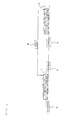
- FIG. 1 is a conceptual view illustrating an example of the configuration of a vehicle to which a vehicle air-conditioning control method according to Embodiment 1 of the present invention is applied
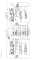
- FIG. 2 is a functional block diagram illustrating an example of the configuration of a vehicle air-conditioning control apparatus to which the vehicle air-conditioning control method according to Embodiment 1 of the present invention is applied.
- FIGs. 1 and 2 are conceptual views illustrating an example of the configuration of a vehicle to which a vehicle air-conditioning control method according to Embodiment 1 of the present invention is applied.
- a vehicle air-conditioning control apparatus for A vehicle 1 that runs between an X station 3 and a Y station 4, to which the vehicle air-conditioning control method according to the present embodiment is applied includes an air-conditioning apparatus 8, an air-conditioning control apparatus 9, an in-vehicle temperature sensor 10, an in-vehicle humidity sensor 11, an outside air temperature sensor 12, a load-compensating sensor 13, a data receiving unit 14 for receiving data 6 obtained between the Y station 4 that is a station next to the X station 3 and a Z station 5 that is a station next to the Y station 4, which is transmitted from another B vehicle 2 on the same vehicle operation form basis, which runs on the same line and directly ahead of the A vehicle 1, and a transmission unit 15 through which the A vehicle 1 transmits data to a vehicle that follows on the same line in the same manner as for the data 6 that is transmitted by the B vehicle 2.
- Examples of the data 6 of the B vehicle 2, which is received by the data receiving unit 14, include a vehicle operation form 16 of the B vehicle 2, position information 17 of the B vehicle 2, information on each train car 18 of the B vehicle 2, an in-vehicle temperature 19 in each train car 18, an in-vehicle humidity 20 in each train car 18, an outside air temperature 21 in each train car 18, and a vehicle occupancy rate 22 in each train car 18.
- FIG. 2 illustrates a configuration in which the outside air temperature sensor 12, the load-compensating sensor 13, the data receiving unit 14, and the data transmission unit 15 are provided for each vehicle, the outside air temperature sensor 12, the load-compensating sensor 13, the data receiving unit 14, and the data transmission unit 15 may be included for each train.
- FIG. 2 illustrates a configuration in which the outside air temperature sensor 12, the load-compensating sensor 13, the data receiving unit 14, and the data transmission unit 15 are provided for each vehicle, the outside air temperature sensor 12, the load-compensating sensor 13, the data receiving unit 14, and the data transmission unit 15 may be included for each train.
- the data 6 is transmitted directly from the B vehicle 2 to the A vehicle 1; as in FIG. 3 , the data 6 may be transmitted to the A vehicle 1 via a terrestrial service computer 7.
- the in-vehicle temperature sensor 10 of the A vehicle 1 which is provided inside the vehicle, measures the temperature inside the vehicle, and outputs an in-vehicle temperature sensor signal, which is the result of the measurement, to the air-conditioning control apparatus 9 of the A vehicle 1.
- the in-vehicle humidity sensor 11 of the A vehicle 1 which is provided inside the vehicle, measures the humidity inside the vehicle, and outputs an in-vehicle humidity sensor signal, which is the result of the measurement, to the air-conditioning control apparatus 9 of the A vehicle 1.
- the outside air temperature sensor 12 of the A vehicle 1 which is provided on the exterior of the vehicle, measures the temperature on the exterior of the vehicle, and outputs an outside air temperature sensor signal, which is the result of the measurement, to the air-conditioning control apparatus 9 of the A vehicle 1.
- sensors in general use may be used and, for example, an electrical load-compensating sensor or a mechanical load-compensating sensor may be used.
- the air-conditioning control apparatus 9 of the A vehicle 1 predicts the air-conditioning reference temperature when the A vehicle 1 will be running between the Y station 4 at which the A vehicle 1 arrives next, and the Z station 5 which is the station after the Y station on the basis of the data 6, such as the outside air temperature 21 and the vehicle occupancy rate 22 received from the B vehicle 2. Then, the air-conditioning apparatus 8 is controlled on the basis of an air-conditioning control pattern corresponding to the air-conditioning reference temperature.
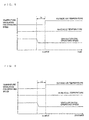
- the air-conditioning reference temperature between the Y station 4 and the Z station 5 at the point of departure from the Y station 4 is set, the air-conditioning control pattern is changed, and the air-conditioning apparatus is controlled, it takes a time of T1 until the actual in-vehicle temperature reaches the air-conditioning reference temperature as shown in FIG. 4 .
- T1 since the inside of the vehicle reaches a temperature higher than a comfortable air-conditioning reference temperature, passengers feel uncomfortable.
- the air-conditioning reference temperature is changed before a predetermined time T2 prior to the expected arrival time to the Y station 4, and the air-conditioning control pattern is changed. Since the in-vehicle temperature of the A vehicle 1 reaches the air-conditioning reference temperature, which is for the vehicle to run through the Y station 4 and the Z station 5, at the time of arrival to the Y station 4, it is possible to prevent the in-vehicle environment from becoming an uncomfortable environment.
- the predetermined time T2 can be changed.
- the vehicle air-conditioning control apparatus to which the vehicle air-conditioning control method according to Embodiment 1 has such a configuration as described above, it is possible to change, before the vehicle arrives at the next station, the air-conditioning control pattern to an air-conditioning control pattern corresponding to the air-conditioning reference temperature when the vehicle runs between the next station and the station after the next station. As a result, from the point when the vehicle arrives at the next station and departs from the next station, comfortable air-conditioning of the inside of the vehicle can be performed.
- Embodiment 2 will be described with reference to FIG. 6 .
- the timing at which the air-conditioning reference temperature is changed is set to be before the predetermined time prior to the arrival to the Y station 4, in Embodiment 2, the air-conditioning reference temperature is changed before a predetermined distance L1 from the Y station 4.
- the other points are the same as those described in Embodiment 1.
- the predetermined distance L1 can be changed.
- Embodiment 3 will be described with reference to FIGs. 2 , 7 and 8 .
- the A vehicle 1 that follows changes the air-conditioning reference temperature on the basis of the data 6 received from the B vehicle 2 that runs ahead of the A vehicle 1.
- a running speed of a ventilation fan is changed before a predetermined time prior to the time when the vehicle reaches the position at which the outside air temperature increases.
- Embodiment 4 the timing at which the running speed of the ventilation fan is changed is set to be before the predetermined time prior to the time when the outside air temperature increases suddenly.
- the running speed of the ventilation fan is changed before a predetermined distance L2 from the spot where the outside air temperature increases suddenly.
- the other points are the same as those described in Embodiment 3.
- the predetermined distance L2 can be changed.
Abstract
Description
- The present invention relates to a vehicle air-conditioning control method for controlling air-conditioning of the interior of a railway vehicle.
- Generally known examples of a vehicle air-conditioning control method include that shown in
FIG. 10 . That is, in the vehicle air-conditioning control method of the related art, as shown inFIG. 10 , electric power input from apantograph 23 is supplied to an auxiliary power-supply device 24, whereby an air-conditioning power is generated and is supplied to an air-conditioning apparatus 25.
The air-conditioning apparatus 25 uses an air-conditioning control apparatus 26 so as to control the number of operating units, the operating frequency, and the running time of air-conditioning compressors inside the air-conditioning apparatus 25, or so as to control the running speed of an electric motor of an indoor fan, thereby performing air-conditioning performance control.
The air-conditioning control apparatus 26 has a microcomputer incorporated thereinto, and an air-conditioning reference temperature stored in a storage area is subjected to various corrections and is sequentially calculated. The various corrections are calculated on the basis of an in-vehicle temperature measured by an in-vehicle temperature sensor 28 provided inside the vehicle, an outside air temperature measured by an outsideair temperature sensor 30 provided on the exterior of the vehicle, an in-vehicle humidity measured by ahumidity sensor 29 provided inside the vehicle, and the occupancy rate of this vehicle, which is measured by a load-compensatingsensor 31 provided in the vehicle. - Hitherto, regarding vehicle occupancy rate and outside air temperature, the vehicle occupancy rate and the outside air temperature when a vehicle is running are measured. Furthermore, there is a method in which inter-station vehicle occupancy rate information for each time zone, which is created in advance on the basis of actual results, has been stored in storage means as inter-station vehicle occupancy rate information on a day of the week basis, on a day of the month basis, on a vehicle operation form basis, or on a vehicle basis (see, for example, PTL 1).
In addition, there is a method in which control of air-conditioning performance is performed on the basis of an air-conditioning load, which is predicted on the basis of the environment information at the present time and the environment information stored in the past (see, for example, PTL 2).
In addition, there is a method in which data including the driving information on an air conditioner and the position information of the vehicle is transmitted periodically to a management computer, and the management computer stores the data and performs processing (see, for example, PTL 3). -
- PTL 1:
- Japanese Patent No.
3 842 688 - PTL 2:
- Japanese Unexamined Patent Application Publication
JP-A-2000-071 740 - PTL 3:
- Japanese Unexamined Patent Application Publication
JP-A-2009-007 006 - However, such a vehicle air-conditioning control method of the related art has the following problems.
In a case where correction of an air-conditioning reference temperature is to be performed on the basis of a vehicle occupancy rate when a vehicle is running, since temperature control is performed in such a way that the number of operating units of air-conditioning compressors incorporated into an air-conditioning apparatus, the operating frequency thereof, and the driving time period thereof are controlled after correction is performed, or the running speed of an electric motor of an indoor fan is controlled so as to make the temperature inside the vehicle approach the air-conditioning reference temperature, it takes time from when the vehicle arrives at the next station until a target air-conditioning reference temperature at which passengers feel comfortable is reached after the vehicle occupancy rate changes. - Furthermore, in a case where correction of an air-conditioning reference temperature is to be performed on the basis of inter-station vehicle occupancy rate information for each time zone, which is created in advance on the basis of actual results stored in storage means in which inter-station vehicle occupancy rate information on a day of the week basis, on a day of the month basis, on a vehicle operation form basis, or on a vehicle basis is stored, there is a problem that a database that stores the information becomes large, hardware and software that predict an inter-station vehicle occupancy rate and the like are necessary, and it takes a lot of time to perform calculation processes.
Furthermore, the stored inter-station vehicle occupancy rate has a problem in that a reliable vehicle occupancy rate cannot be predicted, and the inside of the vehicle cannot be air-conditioned comfortably.
In addition, also, in means for predicting an air-conditioning load on the basis of the environment information stored in the past, there is a problem that the database becomes large, hardware and software that predict an air-conditioning load on the basis of environment information are necessary, and it takes a lot of time to perform calculation processes. - The present invention is made to solve problems described above.
- The vehicle air-conditioning control method according to the present invention is a vehicle air-conditioning control method including:
- calculating an air-conditioning reference temperature for an interior of a vehicle on the basis of an in-vehicle temperature measured by an in-vehicle temperature sensor provided inside a vehicle that runs between stations, an outside air temperature measured by an outside air temperature sensor provided on the exterior of the vehicle, an in-vehicle humidity measured by a humidity sensor provided inside the vehicle, and a vehicle occupancy rate measured by a load-compensating sensor provided in the vehicle;
- determining an air-conditioning control pattern for performing air-conditioning of the inside of the vehicle on the basis of the air-conditioning reference temperature; and
- controlling a vehicle air-conditioning apparatus on the basis of the air-conditioning control pattern.
- According to the present invention of the vehicle air-conditioning control method, by taking means such as the above, a preceding vehicle transmits data detected thereby to a following vehicle, and the following vehicle creates an optimum in-vehicle environment on the basis of the data.
-
- FIG. 1
- is a conceptual view illustrating an example of the configuration of a vehicle to which a vehicle air-conditioning control method according to
Embodiment 1 of the present invention is applied. - FIG. 2
- is a block diagram illustrating an example of the configuration of a vehicle air-conditioning control apparatus to which the vehicle air- conditioning control method according to
Embodiment 1 of the present invention is applied. - FIG. 3
- is a block diagram illustrating an example of the configuration of a vehicle air-conditioning control apparatus to which the vehicle air- conditioning control method according to
Embodiment 1 of the present invention is applied. - FIG. 4
- illustrates an example of the in-vehicle temperature and the change behavior of an air-conditioning control pattern when a vehicle air- conditioning control method of the related art is performed.
- FIG. 5
- illustrates an example of the in-vehicle temperature and the change behavior of an air-conditioning control pattern when the vehicle air- conditioning control method according to
Embodiment 1 of the present invention is applied. - FIG. 6
- illustrates an example of the in-vehicle temperature and the change behavior of an air-conditioning control pattern when a vehicle air- conditioning control method according to
Embodiment 2 of the present invention is applied. - FIG. 7
- illustrates an example of the change behavior of an in-vehicle temperature, the speed pattern of a ventilation fan, and the presence or absence of a tunnel when a vehicle air-conditioning control method of the related art is performed.
- FIG. 8
- illustrates an example of the change behavior of an in-vehicle temperature, the speed pattern of a ventilation fan, and the presence or absence of a tunnel when a vehicle air-conditioning control method according to
Embodiment 3 of the present invention is applied. - FIG. 9
- illustrates an example of the change behavior of an in-vehicle temperature, the speed pattern of a ventilation fan, and the presence or absence of a tunnel when a vehicle air-conditioning control method according to
Embodiment 4 of the present invention is applied. - FIG. 10
- is a block diagram illustrating a vehicle air-conditioning control apparatus of the related art.
-
FIG. 1 is a conceptual view illustrating an example of the configuration of a vehicle to which a vehicle air-conditioning control method according toEmbodiment 1 of the present invention is applied, andFIG. 2 is a functional block diagram illustrating an example of the configuration of a vehicle air-conditioning control apparatus to which the vehicle air-conditioning control method according toEmbodiment 1 of the present invention is applied.
InFIGs. 1 and2 , a vehicle air-conditioning control apparatus forA vehicle 1 that runs between anX station 3 and aY station 4, to which the vehicle air-conditioning control method according to the present embodiment is applied, includes an air-conditioning apparatus 8, an air-conditioning control apparatus 9, an in-vehicle temperature sensor 10, an in-vehicle humidity sensor 11, an outsideair temperature sensor 12, a load-compensatingsensor 13, adata receiving unit 14 for receivingdata 6 obtained between theY station 4 that is a station next to theX station 3 and aZ station 5 that is a station next to theY station 4, which is transmitted from anotherB vehicle 2 on the same vehicle operation form basis, which runs on the same line and directly ahead of theA vehicle 1, and atransmission unit 15 through which theA vehicle 1 transmits data to a vehicle that follows on the same line in the same manner as for thedata 6 that is transmitted by theB vehicle 2.
Examples of thedata 6 of theB vehicle 2, which is received by thedata receiving unit 14, include avehicle operation form 16 of theB vehicle 2,position information 17 of theB vehicle 2, information on eachtrain car 18 of theB vehicle 2, an in-vehicle temperature 19 in eachtrain car 18, an in-vehicle humidity 20 in eachtrain car 18, anoutside air temperature 21 in eachtrain car 18, and avehicle occupancy rate 22 in eachtrain car 18. - Among the above, the air-
conditioning apparatus 8, the air-conditioning control apparatus 9, the in-vehicle temperature sensor 10, and the in-vehicle humidity sensor 11 are provided for each vehicle. AlthoughFIG. 2 illustrates a configuration in which the outsideair temperature sensor 12, the load-compensatingsensor 13, thedata receiving unit 14, and thedata transmission unit 15 are provided for each vehicle, the outsideair temperature sensor 12, the load-compensatingsensor 13, thedata receiving unit 14, and thedata transmission unit 15 may be included for each train.
FIG. 2 illustrates a configuration in which, regarding thedata 6 transmitted to thedata receiving unit 14, the in-vehicle temperature 19 in thetrain car 18, the in-vehicle humidity 20 in thetrain car 18, theoutside air temperature 21 in thetrain car 18, and thevehicle occupancy rate 22 in thetrain car 18 are transmitted.
Instead of the in-vehicle temperature 19, a signal output from the in-vehicle temperature sensor may be used, instead of the in-vehicle humidity 20, a signal output from the in-vehicle humidity sensor may be used, instead of theoutside air temperature 21, a signal output from the outside air temperature sensor may be used, and instead of thevehicle occupancy rate 22, a signal output from the load-compensating sensor may be used.
In addition, inFIGs. 1 and2 , thedata 6 is transmitted directly from theB vehicle 2 to theA vehicle 1; as inFIG. 3 , thedata 6 may be transmitted to theA vehicle 1 via aterrestrial service computer 7. - Descriptions will be given below, with reference to
FIG. 2 , to an embodiment of a vehicle air-conditioning control apparatus to which the vehicle air-conditioning control method that is configured in this manner is applied.
The in-vehicle temperature sensor 10 of theA vehicle 1, which is provided inside the vehicle, measures the temperature inside the vehicle, and outputs an in-vehicle temperature sensor signal, which is the result of the measurement, to the air-conditioning control apparatus 9 of theA vehicle 1.
The in-vehicle humidity sensor 11 of theA vehicle 1, which is provided inside the vehicle, measures the humidity inside the vehicle, and outputs an in-vehicle humidity sensor signal, which is the result of the measurement, to the air-conditioning control apparatus 9 of theA vehicle 1.
The outsideair temperature sensor 12 of theA vehicle 1, which is provided on the exterior of the vehicle, measures the temperature on the exterior of the vehicle, and outputs an outside air temperature sensor signal, which is the result of the measurement, to the air-conditioning control apparatus 9 of theA vehicle 1.
The load-compensatingsensor 13 of theA vehicle 1, which is provided in the vehicle, detects the occupancy rate of the vehicle, and outputs a vehicle occupancy rate signal, which is the result of the measurement, to the air-conditioning control apparatus 9 of theA vehicle 1. For the load-compensatingsensor 13, sensors in general use may be used and, for example, an electrical load-compensating sensor or a mechanical load-compensating sensor may be used. - Before a predetermined time prior to the time when the
A vehicle 1 is expected to arrive at theY station 4 next, the air-conditioning control apparatus 9 of theA vehicle 1 predicts the air-conditioning reference temperature when theA vehicle 1 will be running between theY station 4 at which theA vehicle 1 arrives next, and theZ station 5 which is the station after the Y station on the basis of thedata 6, such as theoutside air temperature 21 and thevehicle occupancy rate 22 received from theB vehicle 2.
Then, the air-conditioning apparatus 8 is controlled on the basis of an air-conditioning control pattern corresponding to the air-conditioning reference temperature. However, in a case where theB vehicle 2 runs apart from theA vehicle 1 by a certain time (for example, 30 minutes) or more, the environments of theB vehicle 2 and theA vehicle 1 may have changed, and the embodiment is not performed. This time can be changed.
If, as in the related art, the air-conditioning reference temperature between theY station 4 and theZ station 5 at the point of departure from theY station 4 is set, the air-conditioning control pattern is changed, and the air-conditioning apparatus is controlled, it takes a time of T1 until the actual in-vehicle temperature reaches the air-conditioning reference temperature as shown inFIG. 4 . During this time of T1, since the inside of the vehicle reaches a temperature higher than a comfortable air-conditioning reference temperature, passengers feel uncomfortable. - In a case where
Embodiment 1 is applied, as shown inFIG. 5 , the air-conditioning reference temperature is changed before a predetermined time T2 prior to the expected arrival time to theY station 4, and the air-conditioning control pattern is changed.
Since the in-vehicle temperature of theA vehicle 1 reaches the air-conditioning reference temperature, which is for the vehicle to run through theY station 4 and theZ station 5, at the time of arrival to theY station 4, it is possible to prevent the in-vehicle environment from becoming an uncomfortable environment. The predetermined time T2 can be changed.
Since the vehicle air-conditioning control apparatus to which the vehicle air-conditioning control method according toEmbodiment 1 has such a configuration as described above, it is possible to change, before the vehicle arrives at the next station, the air-conditioning control pattern to an air-conditioning control pattern corresponding to the air-conditioning reference temperature when the vehicle runs between the next station and the station after the next station.
As a result, from the point when the vehicle arrives at the next station and departs from the next station, comfortable air-conditioning of the inside of the vehicle can be performed. -
Embodiment 2 will be described with reference toFIG. 6 .
Although, inEmbodiment 1, the timing at which the air-conditioning reference temperature is changed is set to be before the predetermined time prior to the arrival to theY station 4, inEmbodiment 2, the air-conditioning reference temperature is changed before a predetermined distance L1 from theY station 4. The other points are the same as those described inEmbodiment 1. The predetermined distance L1 can be changed. -
Embodiment 3 will be described with reference toFIGs. 2 ,7 and8 .
InEmbodiments A vehicle 1 that follows changes the air-conditioning reference temperature on the basis of thedata 6 received from theB vehicle 2 that runs ahead of theA vehicle 1.
However, in a vehicle air-conditioning control apparatus to whichEmbodiment 3 is applied, when theposition information 17 and theoutside air temperature 21 are received from a preceding vehicle and the outside air temperature changes suddenly, a running speed of a ventilation fan is changed before a predetermined time prior to the time when the vehicle reaches the position at which the outside air temperature increases.
In a case where a running vehicle enters a tunnel at an A spot and the outside air temperature increases suddenly, for example, and the vehicle air-conditioning control method of the related art is used, since the in-vehicle temperature increases for the time period of T3 as shown inFIG. 7 , passengers feel uncomfortable.
In a case whereEmbodiment 3 is applied, as shown inFIG. 8 , when the running speed of the ventilation fan is controlled before a predetermined time T4 prior to the time when the vehicle arrives at the A spot at which the outside air temperature increases suddenly, it is possible to prevent the in-vehicle temperature from increasing even after the vehicle arrives at the A spot. The predetermined time T4 can be changed.
Furthermore, in the above description, the running speed of the ventilation fan is controlled. However, the opening/closing of a damper provided in an outside air intake opening may be controlled, or the running speed of the indoor fan may be controlled. - A description will be given below, with reference to
FIG. 9 , ofEmbodiment 4.
InEmbodiment 3 described above, the timing at which the running speed of the ventilation fan is changed is set to be before the predetermined time prior to the time when the outside air temperature increases suddenly.
However, inEmbodiment 4, the running speed of the ventilation fan is changed before a predetermined distance L2 from the spot where the outside air temperature increases suddenly. The other points are the same as those described inEmbodiment 3. The predetermined distance L2 can be changed. - Although
preferred Embodiments 1 to 4 of the present invention have been described in the foregoing while referring to the accompanying drawings, the present invention is not limited to such configurations. A person skilled in the art can conceive various changes or modifications within the scope of the technical concept described in the claims, and it should be understood that those changes or modifications fall within the technical scope of the present invention. -
- 1
- A vehicle
- 2
- B vehicle
- 3
- X station
- 4
- Y station
- 5
- Z station
- 6
- data transmitted from B vehicle
- 7
- service computer
- 8
- air-conditioning apparatus
- 9
- air-conditioning control apparatus
- 10
- in-vehicle temperature sensor
- 11
- in-vehicle humidity sensor
- 12
- outside air temperature sensor
- 13
- load-compensating sensor
- 14
- data receiving unit
- 15
- data transmission unit
- 16
- vehicle operation form information
- 17
- mileage information
- 18
- train car information
- 19
- in-vehicle temperature
- 20
- in-vehicle humidity
- 21
- outside air temperature
- 22
- vehicle occupancy rate
- 23
- pantograph
- 24
- auxiliary power-supply device
- 25
- air-conditioning apparatus
- 26
- air-conditioning control apparatus
- 27
- information control device
- 28
- in-vehicle temperature sensor
- 29
- in-vehicle humidity sensor
- 30
- outside air temperature sensor
- 31
- load-compensating sensor
On the basis of the changed air-conditioning control pattern, a vehicle air-conditioning apparatus, in which the number of operating units of air-conditioning compressors incorporated thereinto, the operating frequency thereof, and the running time thereof are controlled, or a running speed of an electric motor of an indoor fan is controlled, the vehicle air-conditioning apparatus being mounted in the following vehicle, controls an air-conditioning apparatus so as to make the interior of the vehicle comfortable when the following vehicle departs from the next station.
Claims (12)
- A vehicle control method comprising:- calculating an air-conditioning reference temperature for an interior of a vehicle on the basis of an in-vehicle temperature measured by an in-vehicle temperature sensor provided inside the vehicle that runs between stations, an outside air temperature measured by an outside air temperature sensor provided on the exterior of the vehicle, an in-vehicle humidity measured by a humidity sensor provided inside the vehicle, and a vehicle occupancy rate measured by a load-compensating sensor provided in the vehicle;- determining an air-conditioning control pattern for performing air-conditioning of the inside of the vehicle on the basis of the air-conditioning reference temperature; and- controlling a vehicle air-conditioning apparatus on the basis of the air-conditioning control pattern,
wherein the data of a preceding vehicle is received, and is used in air-conditioning control of the following vehicle. - The vehicle air-conditioning control method of claim 1,
wherein when the difference between an in-vehicle temperature between the next station and the station after the next station and the air-conditioning reference temperature is predicted to exceed a predetermined value, the air-conditioning control pattern is changed to an air-conditioning control pattern, which is based on an in-vehicle temperature between the next station and the station after the next station, before a predetermined time prior to the expected arrival time to the next station, and the air-conditioning of the inside of the vehicle is performed by controlling the vehicle air-conditioning apparatus. - The vehicle air-conditioning control method of claim 1,
wherein the in-vehicle temperature measured by a temperature sensor provided inside a train car of a vehicle that is under the same control and
precedes between the next station and the station after the next station, the train car having the same car number as that of the vehicle running behind on the same line, is received by the vehicle running behind the preceding vehicle before a predetermined time prior to the expected arrival time to the next station, the air-conditioning control pattern is changed to an air-conditioning control pattern based on the received in-vehicle temperature before the predetermined time prior to the expected arrival time to the next station, and air-conditioning of the vehicle is performed by controlling the vehicle air-conditioning apparatus. - The vehicle air-conditioning control method of claim 2,
wherein the in-vehicle humidity measured by a humidity sensor provided inside a train car of a vehicle that is under the same control and precedes between the next station and the station after the next station, the train car having the same car number as that of the vehicle running behind on the same line, is received by the vehicle running behind the preceding vehicle, and the air-conditioning control pattern to be changed before the predetermined time period is calculated using the received in-vehicle humidity. - The vehicle air-conditioning control method of claim 2,
wherein the outside air temperature measured by an outside air temperature sensor provided on the exterior of a train car of a vehicle that is under the same control and precedes between the next station and the station after the next station, the train car having the same car number as that of the vehicle running behind on the same line, is received by the vehicle running behind, and the air-conditioning control pattern to be changed before the predetermined time is calculated using the received outside air temperature. - The vehicle air-conditioning control method of claim 2,
wherein the vehicle occupancy rate measured by a load-compensating sensor provided in a train car of a vehicle that is under the same control and precedes between the next station and the station after the next station, the train car having the same car number as that of the vehicle running behind on the same line, is received by the vehicle running behind the preceding vehicle, and the air-conditioning control pattern to be changed before the predetermined time is calculated using the received vehicle occupancy rate. - The vehicle air-conditioning control method of claim 2,
wherein a plurality of data are received from among the in-vehicle temperature measured by the temperature sensor provided inside a train car of a vehicle that is under the same control and precedes between the next station and the station after the next station, the train car having the same car number as that of the vehicle running behind on the same line described in claims 2 to 5, the in-vehicle humidity measured by the humidity sensor provided inside the preceding vehicle, the outside air temperature measured by the outside air temperature sensor provided on the exterior of the preceding vehicle, and the vehicle occupancy rate measured by the load-compensating sensor provided in the preceding vehicle, and the air-conditioning control pattern is calculated using the plurality of received data. - The vehicle air-conditioning control method of claims 1 to 6,
wherein the air-conditioning control pattern is changed before a predetermined distance from the next station rather than before the predetermined time prior to the expected arrival time to the next station. - The vehicle air-conditioning control method of claim 1,
wherein the vehicle receives position information and an outside air temperature of a spot at which an outside air temperature increases or drops suddenly for a train car of a vehicle that is under the same control and precedes on the same line, and a running speed of a ventilation fan is controlled before a predetermined time prior to the expected arrival time to the spot at which the outside air temperature increases or drops suddenly. - The vehicle air-conditioning control method of claim 8,
wherein opening/closing of a damper provided in an outside air intake opening is controlled before the predetermined time prior to the expected arrival time to the spot at which the outside air temperature increases or drops suddenly. - The vehicle air-conditioning control method of claim 8,
wherein a running speed of an indoor fan is controlled before the predetermined time prior to the expected arrival time to the spot at which the outside air temperature increases or drops suddenly. - The vehicle air-conditioning control method of claims 8 to 10,
wherein control is changed before a predetermined distance from the spot at which the outside air temperature increases or drops suddenly rather than before the predetermined time prior to the expected arrival time to the spot at which the outside air temperature increases or drops suddenly.
Applications Claiming Priority (1)
| Application Number | Priority Date | Filing Date | Title |
|---|---|---|---|
| PCT/JP2009/063087 WO2011010369A1 (en) | 2009-07-22 | 2009-07-22 | Vehicle air-conditioning control method |
Publications (3)
| Publication Number | Publication Date |
|---|---|
| EP2457797A1 true EP2457797A1 (en) | 2012-05-30 |
| EP2457797A4 EP2457797A4 (en) | 2013-10-30 |
| EP2457797B1 EP2457797B1 (en) | 2019-09-18 |
Family
ID=43498856
Family Applications (1)
| Application Number | Title | Priority Date | Filing Date |
|---|---|---|---|
| EP09847554.4A Active EP2457797B1 (en) | 2009-07-22 | 2009-07-22 | Vehicle air-conditioning control method |
Country Status (5)
| Country | Link |
|---|---|
| US (1) | US8892277B2 (en) |
| EP (1) | EP2457797B1 (en) |
| JP (1) | JP5100891B2 (en) |
| CN (1) | CN102470881B (en) |
| WO (1) | WO2011010369A1 (en) |
Cited By (2)
| Publication number | Priority date | Publication date | Assignee | Title |
|---|---|---|---|---|
| CN109311488A (en) * | 2016-06-10 | 2019-02-05 | 三菱电机株式会社 | Air conditioner for vehicles and train communication system |
| WO2023030831A1 (en) * | 2021-09-06 | 2023-03-09 | Siemens Mobility GmbH | Method for monitoring an air-conditioned passenger compartment of a vehicle, and air-conditioning arrangement for carrying out such a method |
Families Citing this family (12)
| Publication number | Priority date | Publication date | Assignee | Title |
|---|---|---|---|---|
| JP5679715B2 (en) * | 2010-07-07 | 2015-03-04 | 三菱電機株式会社 | Air conditioner for vehicles |
| JP5679835B2 (en) * | 2011-01-21 | 2015-03-04 | 三菱電機株式会社 | Vehicle air conditioner and vehicle |
| WO2014112320A1 (en) | 2013-01-17 | 2014-07-24 | 三菱電機株式会社 | Vehicle air conditioning control device |
| US9849751B2 (en) | 2015-01-14 | 2017-12-26 | Ford Global Technologies, Llc | Adaptive control of automotive HVAC system using crowd-sourcing data |
| CN104943704B (en) * | 2015-06-12 | 2017-08-01 | 石家庄国祥运输设备有限公司 | A kind of method that railway vehicle air conditioner realizes humid control by refrigerating function |
| TWI547391B (en) * | 2015-09-01 | 2016-09-01 | 華邦電子股份有限公司 | Control system and control method for air condition of traffic vehicle |
| WO2017212631A1 (en) * | 2016-06-10 | 2017-12-14 | 三菱電機株式会社 | Vehicle air-conditioning device and abnormality detection system for vehicle air-conditioning device |
| CN109311489B (en) * | 2016-06-10 | 2021-08-10 | 三菱电机株式会社 | Air conditioner for vehicle and jam detection system for air conditioner for vehicle |
| JP6606481B2 (en) * | 2016-09-07 | 2019-11-13 | 日立建機株式会社 | Dump truck and cooling fan control method |
| CN106338127B (en) * | 2016-09-20 | 2018-06-22 | 珠海格力电器股份有限公司 | For the load prediction of subway heating ventilation air-conditioning system and control system and its method |
| US10675939B2 (en) | 2017-01-17 | 2020-06-09 | International Business Machines Corporation | Pre-cooling and pre-heating transportation vehicles using predictive crowd estimation techniques |
| US20190136816A1 (en) * | 2017-11-07 | 2019-05-09 | Panasonic Automotive Systems Company Of America, Division Of Panasonic Corporation Of North America | Vehicle ignition on a schedule |
Citations (5)
| Publication number | Priority date | Publication date | Assignee | Title |
|---|---|---|---|---|
| DE2633243A1 (en) * | 1975-07-30 | 1977-02-10 | Friedmann Kg Alex | Railway passenger coach air conditioning system - uses monitor in selected compartment to control supply of additional heat depending on occupancy |
| EP0149450A2 (en) * | 1983-12-30 | 1985-07-24 | Alex. Friedmann Kommanditgesellschaft | Air conditioning device for railroad vehicles |
| GB2267146A (en) * | 1992-04-22 | 1993-11-24 | Norm Pacific Automat Corp | Air conditioning apparatus |
| EP0610692A1 (en) * | 1993-02-12 | 1994-08-17 | HAGENUK FAHRZEUGKLIMA GmbH | Method and device for controlling the rate of fresh air in high speed trains |
| WO2002074600A1 (en) * | 2001-03-21 | 2002-09-26 | Bombardier Transportation Gmbh | Method and assembly for controlling the air conditioning of high-speed vehicles |
Family Cites Families (15)
| Publication number | Priority date | Publication date | Assignee | Title |
|---|---|---|---|---|
| US2469555A (en) * | 1945-06-19 | 1949-05-10 | Gen Railway Signal Co | Selective radio communication system for a plurality of stations |
| JPS63207766A (en) | 1987-02-25 | 1988-08-29 | 株式会社日立製作所 | Method of controlling air conditioner for car |
| US5104037A (en) * | 1990-10-26 | 1992-04-14 | Aeg Westinghouse Transportation Systems, Inc. | Microprocessor controlled climate control device for a plurality of mass transit vehicles |
| JPH0664536A (en) | 1992-08-21 | 1994-03-08 | Mitsubishi Electric Corp | Vehicle cooling control device |
| JP2913620B2 (en) | 1996-08-12 | 1999-06-28 | 川崎重工業株式会社 | Ventilation control device for vehicles |
| JP2000071740A (en) | 1998-08-27 | 2000-03-07 | Mitsubishi Heavy Ind Ltd | Air conditioning system for vehicle |
| JP2001030903A (en) * | 1999-07-23 | 2001-02-06 | Fuji Electric Co Ltd | Electric railcar operation data collecting system |
| JP2001088699A (en) | 1999-09-24 | 2001-04-03 | Calsonic Kansei Corp | Air conditioner for rolling stock |
| JP2002284005A (en) | 2001-03-27 | 2002-10-03 | Mitsubishi Electric Corp | Air conditioning controller for railroad rolling stock and air conditioning control information collection system for railroad rolling stock |
| JP3842688B2 (en) | 2002-03-29 | 2006-11-08 | 株式会社東芝 | Vehicle air conditioning control method |
| JP2003312474A (en) | 2002-04-17 | 2003-11-06 | Hitachi Ltd | Method of controlling dehumidification in air-conditioner for rolling stock, and rolling stock air-conditioner |
| JP4244676B2 (en) | 2003-03-28 | 2009-03-25 | 三菱電機株式会社 | Vehicle air conditioning management system |
| JP4346429B2 (en) * | 2003-12-16 | 2009-10-21 | 株式会社東芝 | Air conditioner for vehicles |
| JP4958421B2 (en) * | 2005-09-22 | 2012-06-20 | 三菱電機株式会社 | Air conditioning system for railway vehicles |
| JP5040887B2 (en) | 2008-10-17 | 2012-10-03 | 三菱電機株式会社 | Vehicle air conditioning management system |
-
2009
- 2009-07-22 WO PCT/JP2009/063087 patent/WO2011010369A1/en active Application Filing
- 2009-07-22 US US13/382,744 patent/US8892277B2/en active Active
- 2009-07-22 JP JP2011523509A patent/JP5100891B2/en active Active
- 2009-07-22 CN CN200980160525.9A patent/CN102470881B/en active Active
- 2009-07-22 EP EP09847554.4A patent/EP2457797B1/en active Active
Patent Citations (5)
| Publication number | Priority date | Publication date | Assignee | Title |
|---|---|---|---|---|
| DE2633243A1 (en) * | 1975-07-30 | 1977-02-10 | Friedmann Kg Alex | Railway passenger coach air conditioning system - uses monitor in selected compartment to control supply of additional heat depending on occupancy |
| EP0149450A2 (en) * | 1983-12-30 | 1985-07-24 | Alex. Friedmann Kommanditgesellschaft | Air conditioning device for railroad vehicles |
| GB2267146A (en) * | 1992-04-22 | 1993-11-24 | Norm Pacific Automat Corp | Air conditioning apparatus |
| EP0610692A1 (en) * | 1993-02-12 | 1994-08-17 | HAGENUK FAHRZEUGKLIMA GmbH | Method and device for controlling the rate of fresh air in high speed trains |
| WO2002074600A1 (en) * | 2001-03-21 | 2002-09-26 | Bombardier Transportation Gmbh | Method and assembly for controlling the air conditioning of high-speed vehicles |
Non-Patent Citations (1)
| Title |
|---|
| See also references of WO2011010369A1 * |
Cited By (5)
| Publication number | Priority date | Publication date | Assignee | Title |
|---|---|---|---|---|
| CN109311488A (en) * | 2016-06-10 | 2019-02-05 | 三菱电机株式会社 | Air conditioner for vehicles and train communication system |
| EP3470291A4 (en) * | 2016-06-10 | 2019-06-26 | Mitsubishi Electric Corporation | Vehicle air-conditioning device and railroad-car communication system |
| US10654494B2 (en) | 2016-06-10 | 2020-05-19 | Mitsubishi Electric Corporation | Vehicle air-conditioning device and train communication system |
| CN109311488B (en) * | 2016-06-10 | 2021-04-09 | 三菱电机株式会社 | Air conditioner for vehicle and train communication system |
| WO2023030831A1 (en) * | 2021-09-06 | 2023-03-09 | Siemens Mobility GmbH | Method for monitoring an air-conditioned passenger compartment of a vehicle, and air-conditioning arrangement for carrying out such a method |
Also Published As
| Publication number | Publication date |
|---|---|
| WO2011010369A1 (en) | 2011-01-27 |
| EP2457797A4 (en) | 2013-10-30 |
| CN102470881A (en) | 2012-05-23 |
| JPWO2011010369A1 (en) | 2012-12-27 |
| EP2457797B1 (en) | 2019-09-18 |
| US20120109429A1 (en) | 2012-05-03 |
| CN102470881B (en) | 2014-07-30 |
| JP5100891B2 (en) | 2012-12-19 |
| US8892277B2 (en) | 2014-11-18 |
Similar Documents
| Publication | Publication Date | Title |
|---|---|---|
| US8892277B2 (en) | Vehicle air-conditioning control method | |
| JP5679715B2 (en) | Air conditioner for vehicles | |
| US9786170B2 (en) | In-vehicle notification presentation scheduling | |
| US10435050B2 (en) | Method for monitoring and diagnosing components of a rail vehicle by means of an extensible evaluation software | |
| JP5679835B2 (en) | Vehicle air conditioner and vehicle | |
| JP3842688B2 (en) | Vehicle air conditioning control method | |
| US10032377B2 (en) | Parking space management | |
| JP6141035B2 (en) | Train control system and automatic train operation device | |
| JP2010210271A (en) | Navigation device and destination arrival possibility determination method | |
| US11267316B2 (en) | Air conditioning control device, air conditioning control method, and program | |
| EP2669142A2 (en) | Vehicle system | |
| CN111422036B (en) | Ventilation control system, control method thereof, and non-transitory computer-readable medium | |
| CN102470886B (en) | Operational support device for vehicle not powered by overhead electric wire | |
| JP2019160242A (en) | Communication device and method for creating schedule | |
| US11961025B2 (en) | Automated driving vehicle, and method for controlling the vehicle | |
| JP2005082088A (en) | Air conditioning control system | |
| KR20140124937A (en) | Eco-Driving Device and method for electric railway vehicles | |
| KR100931334B1 (en) | Shortest path setting system for small track vehicles | |
| US20200114941A1 (en) | Vehicle communication system | |
| JP2005345029A (en) | Environment providing control system and environment providing control method | |
| JP5679712B2 (en) | Vehicle equipment control device | |
| JP4507945B2 (en) | Operation management system | |
| JP7428555B2 (en) | Control device, system, program, and control method | |
| JP7405445B2 (en) | System and method for adjusting elevator load settings | |
| JP2022162442A (en) | Bus dispatching device, bus dispatching method, and computer program for bus dispatching |
Legal Events
| Date | Code | Title | Description |
|---|---|---|---|
| PUAI | Public reference made under article 153(3) epc to a published international application that has entered the european phase |
Free format text: ORIGINAL CODE: 0009012 |
|
| 17P | Request for examination filed |
Effective date: 20120119 |
|
| AK | Designated contracting states |
Kind code of ref document: A1 Designated state(s): AT BE BG CH CY CZ DE DK EE ES FI FR GB GR HR HU IE IS IT LI LT LU LV MC MK MT NL NO PL PT RO SE SI SK SM TR |
|
| DAX | Request for extension of the european patent (deleted) | ||
| A4 | Supplementary search report drawn up and despatched |
Effective date: 20130926 |
|
| RIC1 | Information provided on ipc code assigned before grant |
Ipc: B61D 27/00 20060101AFI20130920BHEP |
|
| STAA | Information on the status of an ep patent application or granted ep patent |
Free format text: STATUS: EXAMINATION IS IN PROGRESS |
|
| 17Q | First examination report despatched |
Effective date: 20171116 |
|
| GRAP | Despatch of communication of intention to grant a patent |
Free format text: ORIGINAL CODE: EPIDOSNIGR1 |
|
| STAA | Information on the status of an ep patent application or granted ep patent |
Free format text: STATUS: GRANT OF PATENT IS INTENDED |
|
| INTG | Intention to grant announced |
Effective date: 20190329 |
|
| GRAS | Grant fee paid |
Free format text: ORIGINAL CODE: EPIDOSNIGR3 |
|
| GRAA | (expected) grant |
Free format text: ORIGINAL CODE: 0009210 |
|
| STAA | Information on the status of an ep patent application or granted ep patent |
Free format text: STATUS: THE PATENT HAS BEEN GRANTED |
|
| AK | Designated contracting states |
Kind code of ref document: B1 Designated state(s): AT BE BG CH CY CZ DE DK EE ES FI FR GB GR HR HU IE IS IT LI LT LU LV MC MK MT NL NO PL PT RO SE SI SK SM TR |
|
| REG | Reference to a national code |
Ref country code: GB Ref legal event code: FG4D |
|
| REG | Reference to a national code |
Ref country code: CH Ref legal event code: EP |
|
| REG | Reference to a national code |
Ref country code: DE Ref legal event code: R096 Ref document number: 602009059924 Country of ref document: DE |
|
| REG | Reference to a national code |
Ref country code: AT Ref legal event code: REF Ref document number: 1180934 Country of ref document: AT Kind code of ref document: T Effective date: 20191015 |
|
| REG | Reference to a national code |
Ref country code: IE Ref legal event code: FG4D |
|
| REG | Reference to a national code |
Ref country code: NL Ref legal event code: MP Effective date: 20190918 |
|
| PG25 | Lapsed in a contracting state [announced via postgrant information from national office to epo] |
Ref country code: NO Free format text: LAPSE BECAUSE OF FAILURE TO SUBMIT A TRANSLATION OF THE DESCRIPTION OR TO PAY THE FEE WITHIN THE PRESCRIBED TIME-LIMIT Effective date: 20191218 Ref country code: SE Free format text: LAPSE BECAUSE OF FAILURE TO SUBMIT A TRANSLATION OF THE DESCRIPTION OR TO PAY THE FEE WITHIN THE PRESCRIBED TIME-LIMIT Effective date: 20190918 Ref country code: BG Free format text: LAPSE BECAUSE OF FAILURE TO SUBMIT A TRANSLATION OF THE DESCRIPTION OR TO PAY THE FEE WITHIN THE PRESCRIBED TIME-LIMIT Effective date: 20191218 Ref country code: HR Free format text: LAPSE BECAUSE OF FAILURE TO SUBMIT A TRANSLATION OF THE DESCRIPTION OR TO PAY THE FEE WITHIN THE PRESCRIBED TIME-LIMIT Effective date: 20190918 Ref country code: LT Free format text: LAPSE BECAUSE OF FAILURE TO SUBMIT A TRANSLATION OF THE DESCRIPTION OR TO PAY THE FEE WITHIN THE PRESCRIBED TIME-LIMIT Effective date: 20190918 Ref country code: FI Free format text: LAPSE BECAUSE OF FAILURE TO SUBMIT A TRANSLATION OF THE DESCRIPTION OR TO PAY THE FEE WITHIN THE PRESCRIBED TIME-LIMIT Effective date: 20190918 |
|
| REG | Reference to a national code |
Ref country code: LT Ref legal event code: MG4D |
|
| PG25 | Lapsed in a contracting state [announced via postgrant information from national office to epo] |
Ref country code: GR Free format text: LAPSE BECAUSE OF FAILURE TO SUBMIT A TRANSLATION OF THE DESCRIPTION OR TO PAY THE FEE WITHIN THE PRESCRIBED TIME-LIMIT Effective date: 20191219 Ref country code: LV Free format text: LAPSE BECAUSE OF FAILURE TO SUBMIT A TRANSLATION OF THE DESCRIPTION OR TO PAY THE FEE WITHIN THE PRESCRIBED TIME-LIMIT Effective date: 20190918 |
|
| REG | Reference to a national code |
Ref country code: AT Ref legal event code: MK05 Ref document number: 1180934 Country of ref document: AT Kind code of ref document: T Effective date: 20190918 |
|
| PG25 | Lapsed in a contracting state [announced via postgrant information from national office to epo] |
Ref country code: ES Free format text: LAPSE BECAUSE OF FAILURE TO SUBMIT A TRANSLATION OF THE DESCRIPTION OR TO PAY THE FEE WITHIN THE PRESCRIBED TIME-LIMIT Effective date: 20190918 Ref country code: RO Free format text: LAPSE BECAUSE OF FAILURE TO SUBMIT A TRANSLATION OF THE DESCRIPTION OR TO PAY THE FEE WITHIN THE PRESCRIBED TIME-LIMIT Effective date: 20190918 Ref country code: NL Free format text: LAPSE BECAUSE OF FAILURE TO SUBMIT A TRANSLATION OF THE DESCRIPTION OR TO PAY THE FEE WITHIN THE PRESCRIBED TIME-LIMIT Effective date: 20190918 Ref country code: AT Free format text: LAPSE BECAUSE OF FAILURE TO SUBMIT A TRANSLATION OF THE DESCRIPTION OR TO PAY THE FEE WITHIN THE PRESCRIBED TIME-LIMIT Effective date: 20190918 Ref country code: EE Free format text: LAPSE BECAUSE OF FAILURE TO SUBMIT A TRANSLATION OF THE DESCRIPTION OR TO PAY THE FEE WITHIN THE PRESCRIBED TIME-LIMIT Effective date: 20190918 Ref country code: PL Free format text: LAPSE BECAUSE OF FAILURE TO SUBMIT A TRANSLATION OF THE DESCRIPTION OR TO PAY THE FEE WITHIN THE PRESCRIBED TIME-LIMIT Effective date: 20190918 Ref country code: PT Free format text: LAPSE BECAUSE OF FAILURE TO SUBMIT A TRANSLATION OF THE DESCRIPTION OR TO PAY THE FEE WITHIN THE PRESCRIBED TIME-LIMIT Effective date: 20200120 |
|
| PG25 | Lapsed in a contracting state [announced via postgrant information from national office to epo] |
Ref country code: IS Free format text: LAPSE BECAUSE OF FAILURE TO SUBMIT A TRANSLATION OF THE DESCRIPTION OR TO PAY THE FEE WITHIN THE PRESCRIBED TIME-LIMIT Effective date: 20200224 Ref country code: SK Free format text: LAPSE BECAUSE OF FAILURE TO SUBMIT A TRANSLATION OF THE DESCRIPTION OR TO PAY THE FEE WITHIN THE PRESCRIBED TIME-LIMIT Effective date: 20190918 Ref country code: SM Free format text: LAPSE BECAUSE OF FAILURE TO SUBMIT A TRANSLATION OF THE DESCRIPTION OR TO PAY THE FEE WITHIN THE PRESCRIBED TIME-LIMIT Effective date: 20190918 Ref country code: CZ Free format text: LAPSE BECAUSE OF FAILURE TO SUBMIT A TRANSLATION OF THE DESCRIPTION OR TO PAY THE FEE WITHIN THE PRESCRIBED TIME-LIMIT Effective date: 20190918 |
|
| REG | Reference to a national code |
Ref country code: DE Ref legal event code: R097 Ref document number: 602009059924 Country of ref document: DE |
|
| PLBE | No opposition filed within time limit |
Free format text: ORIGINAL CODE: 0009261 |
|
| STAA | Information on the status of an ep patent application or granted ep patent |
Free format text: STATUS: NO OPPOSITION FILED WITHIN TIME LIMIT |
|
| PG2D | Information on lapse in contracting state deleted |
Ref country code: IS |
|
| PG25 | Lapsed in a contracting state [announced via postgrant information from national office to epo] |
Ref country code: DK Free format text: LAPSE BECAUSE OF FAILURE TO SUBMIT A TRANSLATION OF THE DESCRIPTION OR TO PAY THE FEE WITHIN THE PRESCRIBED TIME-LIMIT Effective date: 20190918 Ref country code: IS Free format text: LAPSE BECAUSE OF FAILURE TO SUBMIT A TRANSLATION OF THE DESCRIPTION OR TO PAY THE FEE WITHIN THE PRESCRIBED TIME-LIMIT Effective date: 20200119 |
|
| 26N | No opposition filed |
Effective date: 20200619 |
|
| PG25 | Lapsed in a contracting state [announced via postgrant information from national office to epo] |
Ref country code: SI Free format text: LAPSE BECAUSE OF FAILURE TO SUBMIT A TRANSLATION OF THE DESCRIPTION OR TO PAY THE FEE WITHIN THE PRESCRIBED TIME-LIMIT Effective date: 20190918 |
|
| PG25 | Lapsed in a contracting state [announced via postgrant information from national office to epo] |
Ref country code: MC Free format text: LAPSE BECAUSE OF FAILURE TO SUBMIT A TRANSLATION OF THE DESCRIPTION OR TO PAY THE FEE WITHIN THE PRESCRIBED TIME-LIMIT Effective date: 20190918 |
|
| REG | Reference to a national code |
Ref country code: CH Ref legal event code: PL |
|
| REG | Reference to a national code |
Ref country code: BE Ref legal event code: MM Effective date: 20200731 |
|
| PG25 | Lapsed in a contracting state [announced via postgrant information from national office to epo] |
Ref country code: LU Free format text: LAPSE BECAUSE OF NON-PAYMENT OF DUE FEES Effective date: 20200722 Ref country code: CH Free format text: LAPSE BECAUSE OF NON-PAYMENT OF DUE FEES Effective date: 20200731 Ref country code: LI Free format text: LAPSE BECAUSE OF NON-PAYMENT OF DUE FEES Effective date: 20200731 |
|
| PG25 | Lapsed in a contracting state [announced via postgrant information from national office to epo] |
Ref country code: BE Free format text: LAPSE BECAUSE OF NON-PAYMENT OF DUE FEES Effective date: 20200731 |
|
| PG25 | Lapsed in a contracting state [announced via postgrant information from national office to epo] |
Ref country code: IE Free format text: LAPSE BECAUSE OF NON-PAYMENT OF DUE FEES Effective date: 20200722 |
|
| PG25 | Lapsed in a contracting state [announced via postgrant information from national office to epo] |
Ref country code: TR Free format text: LAPSE BECAUSE OF FAILURE TO SUBMIT A TRANSLATION OF THE DESCRIPTION OR TO PAY THE FEE WITHIN THE PRESCRIBED TIME-LIMIT Effective date: 20190918 Ref country code: MT Free format text: LAPSE BECAUSE OF FAILURE TO SUBMIT A TRANSLATION OF THE DESCRIPTION OR TO PAY THE FEE WITHIN THE PRESCRIBED TIME-LIMIT Effective date: 20190918 Ref country code: CY Free format text: LAPSE BECAUSE OF FAILURE TO SUBMIT A TRANSLATION OF THE DESCRIPTION OR TO PAY THE FEE WITHIN THE PRESCRIBED TIME-LIMIT Effective date: 20190918 |
|
| PG25 | Lapsed in a contracting state [announced via postgrant information from national office to epo] |
Ref country code: MK Free format text: LAPSE BECAUSE OF FAILURE TO SUBMIT A TRANSLATION OF THE DESCRIPTION OR TO PAY THE FEE WITHIN THE PRESCRIBED TIME-LIMIT Effective date: 20190918 |
|
| REG | Reference to a national code |
Ref country code: DE Ref legal event code: R084 Ref document number: 602009059924 Country of ref document: DE |
|
| REG | Reference to a national code |
Ref country code: GB Ref legal event code: 746 Effective date: 20221229 |
|
| P01 | Opt-out of the competence of the unified patent court (upc) registered |
Effective date: 20230512 |
|
| PGFP | Annual fee paid to national office [announced via postgrant information from national office to epo] |
Ref country code: IT Payment date: 20230612 Year of fee payment: 15 Ref country code: FR Payment date: 20230608 Year of fee payment: 15 |
|
| PGFP | Annual fee paid to national office [announced via postgrant information from national office to epo] |
Ref country code: GB Payment date: 20230601 Year of fee payment: 15 |
|
| PGFP | Annual fee paid to national office [announced via postgrant information from national office to epo] |
Ref country code: DE Payment date: 20230531 Year of fee payment: 15 |