JP5100891B2 - Vehicle air conditioning control method - Google Patents
Vehicle air conditioning control method Download PDFInfo
- Publication number
- JP5100891B2 JP5100891B2 JP2011523509A JP2011523509A JP5100891B2 JP 5100891 B2 JP5100891 B2 JP 5100891B2 JP 2011523509 A JP2011523509 A JP 2011523509A JP 2011523509 A JP2011523509 A JP 2011523509A JP 5100891 B2 JP5100891 B2 JP 5100891B2
- Authority
- JP
- Japan
- Prior art keywords
- vehicle
- conditioning control
- air
- air conditioning
- temperature
- Prior art date
- Legal status (The legal status is an assumption and is not a legal conclusion. Google has not performed a legal analysis and makes no representation as to the accuracy of the status listed.)
- Active
Links
Images


Classifications
-
- B—PERFORMING OPERATIONS; TRANSPORTING
- B61—RAILWAYS
- B61D—BODY DETAILS OR KINDS OF RAILWAY VEHICLES
- B61D27/00—Heating, cooling, ventilating, or air-conditioning
- B61D27/0072—Means for cooling only
Landscapes
- Engineering & Computer Science (AREA)
- Mechanical Engineering (AREA)
- Air-Conditioning For Vehicles (AREA)
Description
本発明は、鉄道車両内部の空調を制御するための車両用空調制御方法に関するものである。 The present invention relates to a vehicle air conditioning control method for controlling air conditioning inside a railway vehicle.
一般に車両用空調制御方法においては、図10に示されるものが知られている。すなわち、従来の車両用空調制御方法では、図10に示すように、パンタグラフ23より入力される電力が補助電源装置24に与えられ、ここで、空調用電源が生成されて、空調装置25に供給される。空調装置25は空調制御装置26によって、空調装置25内の空調コンプレッサの運転台数や運転周波数、運転時間を制御し、あるいは室内送風機の電動機の運転速度を制御して空調能力制御が行われる。
空調制御装置26はマイクロコンピュータを搭載しており、記憶領域に記憶された空調基準温度は、各種補正が行われ、逐次算出されている。前記各種補正は、車両の内部に設けられた車内温度センサ28によって測定された車内温度と、前記車両の外部に設けられた外気温度センサ30によって測定された外気温度と、前記車両の内部に設けられた湿度センサ29によって測定された車内湿度と、前記車両に設けられた応荷重センサ31によって測定されたこの車両の乗車率とに基づいて算出されている。In general, a vehicle air conditioning control method shown in FIG. 10 is known. That is, in the conventional vehicle air conditioning control method, as shown in FIG. 10, the electric power input from the
The air
従来、前記乗車率と外気温度に関しては、車両が走行している時点の乗車率や外気温度を測定している。また、実績に基づき予め作成された時間帯毎の駅間乗車率情報を曜日別と月日別、車両運用形態別、車両別の駅間乗車率情報を記憶手段に蓄積しているものがある(例えば、特許文献1参照)。
さらにまた、現在の環境情報と過去に記憶した環境情報とに基づいて予測された空調負荷に基づき、空調能力の制御を行うものがある(例えば、特許文献2参照)。
そして、さらにまた、空調機の運転情報と、車両の位置情報とを有するデータを定期的に管理コンピュータに送信し、管理コンピュータがデータを蓄積し、処理するものがある(例えば、特許文献3参照)。Conventionally, with regard to the boarding rate and the outside air temperature, the boarding rate and the outside air temperature at the time when the vehicle is running are measured. In addition, there is a storage unit that stores the inter-station boarding rate information for each time zone that is created in advance based on the results, by day of the week, by month, day, by vehicle operation mode, and by vehicle. (For example, refer to Patent Document 1).
Furthermore, there is one that controls the air conditioning capability based on the air conditioning load predicted based on the current environmental information and the environmental information stored in the past (see, for example, Patent Document 2).
Further, there is one that periodically transmits data having air conditioner operation information and vehicle position information to the management computer, and the management computer stores and processes the data (see, for example, Patent Document 3). ).
しかしながら、このような従来の車両用空調制御方法では、以下のような課題がある。
車両が走行している時点の乗車率から空調基準温度の補正を行う場合、補正を行った後に空調装置に内蔵される空調コンプレッサの運転台数や運転周波数、運転時間を制御し、あるいは室内送風機の電動機の運転速度を制御し、空調基準温度に車両内の温度を近づけるよう温度制御を実施するため、前記車両が次駅に到着し、乗車率が変化してから、乗客が快適と感じられる目標の空調基準温度に到達するまでに時間がかかってしまうという課題があった。However, such a conventional vehicle air conditioning control method has the following problems.
When correcting the air conditioning reference temperature based on the boarding rate at the time when the vehicle is traveling, the number of operating air conditioning compressors, the operating frequency, and the operating time are controlled after the correction, or the indoor fan Targets that passengers feel comfortable after the vehicle arrives at the next station and the boarding rate changes in order to control the operating speed of the motor and to control the temperature so that the temperature inside the vehicle approaches the air conditioning reference temperature There is a problem that it takes time to reach the air conditioning reference temperature.
また、曜日別と月日別、車両運用形態別、車両別の駅間乗車率情報を記憶手段に蓄積している実績に基づき予め作成された時間帯毎の駅間乗車率情報から空調基準温度の補正を行う場合、蓄積するデータベースが肥大化し、駅間乗車率等を予測するハードウェアやソフトウェアが必要で、かつ計算処理に多大な時間が生じてしまうという課題があった。また、蓄積された駅間乗車率では、確実な乗車率を予測できず、車内を快適に空調できないという課題があった。
さらにまた、過去に記憶した環境情報とに基づいて空調負荷を予測する手段においても、データベースが肥大化し、環境情報に基づいて空調負荷を予測するハードウェアやソフトウェアが必要で、かつ計算処理に多大な時間が生じてしまうという課題があった。In addition, the air conditioning reference temperature is calculated from the inter-station boarding rate information for each time zone that is created in advance based on the results of storing the inter-station boarding rate information for each day of the week, month, day, vehicle operation type, and vehicle in the storage means. When the correction is performed, there is a problem that a database to be accumulated is enlarged, hardware and software for predicting an inter-station boarding rate and the like are necessary, and much time is required for calculation processing. Moreover, the accumulated inter-station boarding rate cannot predict a reliable boarding rate, and there is a problem that the inside of the vehicle cannot be comfortably air-conditioned.
Furthermore, in the means for predicting the air conditioning load based on the environmental information stored in the past, the database is enlarged, hardware and software for predicting the air conditioning load based on the environmental information are necessary, and the calculation processing is very large. There was a problem that a long time would occur.
本発明は、上記のような課題を解決するためになされたものである。 The present invention has been made to solve the above-described problems.
本発明に係る車両用空調制御方法は、走行する車両の内部に設けられた車内温度センサによって測定された車内温度と、車両の外部に設けられた外気温度センサによって測定された外気温度と、車両の内部に設けられた湿度センサによって測定された車内湿度と、車両に設けられた応荷重センサによって測定されたこの車両の乗車率とに基づいて、車両内の空調基準温度を演算し、空調基準温度に基づいて、車両内を空調するための空調制御パターンを決定し、この空調制御パターンに基づいて、車両用空調装置を制御する車両用空調制御方法であって、後続車両が置かれている環境とほぼ同じと考えられる同じ路線の一つ前を先行する同じ運用車両の同じ号車から、この後続車両にとっての次駅と次々駅の間で測定された先行車両のデータを後続車両に送信し、後続車両がこの受信したデータに基づいて、空調能力の変更に基づいた空調制御パターンの変更を次駅に到着する前に実施し、この変更された空調制御パターンに基づき、後続車両に搭載される車両用空調装置は、内蔵される空調コンプレッサの運転台数や運転周波数、運転時間を制御され、あるいは室内送風機の電動機の運転速度が制御され、後続車両が次駅を出発する時点で、車内が快適になるように空調装置を制御する。 An air conditioning control method for a vehicle according to the present invention includes an in-vehicle temperature measured by an in-vehicle temperature sensor provided inside a traveling vehicle, an outside air temperature measured by an outside air temperature sensor provided outside the vehicle, and the vehicle Based on the in-vehicle humidity measured by the humidity sensor provided inside the vehicle and the boarding rate of the vehicle measured by the variable load sensor provided in the vehicle, the air-conditioning reference temperature in the vehicle is calculated, and the air-conditioning reference A vehicle air conditioning control method for determining an air conditioning control pattern for air conditioning a vehicle based on temperature and controlling a vehicle air conditioner based on the air conditioning control pattern, in which a succeeding vehicle is placed Data of the preceding vehicle measured between the next station and the next station for this succeeding vehicle from the same car of the same operating vehicle preceding the same route considered to be almost the same as the environment Based on this received data, the succeeding vehicle transmits a change in the air conditioning control pattern based on the change in the air conditioning capacity before arriving at the next station, and based on the changed air conditioning control pattern, The vehicle air conditioner mounted in the succeeding vehicle is controlled in the number of operating air conditioner compressors, operating frequency and operating time, or the operating speed of the motor of the indoor fan is controlled, and the succeeding vehicle departs from the next station. At that time, the air conditioner is controlled so that the interior of the vehicle becomes comfortable.
本車両用空調制御方法の発明によれば、以上のような手段を講じることにより、先行する車両が検出したデータを後続する車両に送信し、そのデータに基づいて後続の車両は最適な車内空間を創出する。 According to the invention of the air conditioning control method for a vehicle, by taking the above-described means, the data detected by the preceding vehicle is transmitted to the succeeding vehicle, and the succeeding vehicle is based on the data so that the optimum interior space is obtained. Create.
実施の形態1.
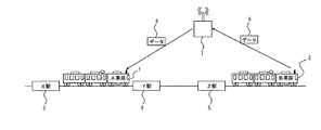
図1は、この発明の実施の形態1に係わる車両用空調制御方法を適用した車両の構成例を示す概念図であり、図2はこの発明の実施の形態1に係わる車両用空調制御方法を適用した車両用空調制御装置の構成例を示す機能ブロック図である。
図1、図2において、本実施の形態に係わる車両用空調制御方法を適用したX駅3とY駅4の間を走行するA車両1の車両用空調制御装置は、空調装置8と、空調制御装置9と、車内温度センサ10と、車内湿度センサ11と、外気温度センサ12と、応荷重センサ13とA車両1と同じ路線の一つ前を先行して走る同じ車両運用形態別のB車両2から送信されたX駅3の次駅であるY駅4とY駅4の次駅であるZ駅5の間に取得されたデータ6を受信するためのデータ受信部14と、B車両2が送信するデータ6と同様にA車両1が同じ路線を後続する車両にデータを送信する送信部15とを備えている。
なお、データ受信部14に受信されるB車両2のデータ6には、B車両2の車両運用形態16と、B車両2の位置情報17と、B車両2のそれぞれの号車情報18と、前記それぞれの号車18における車内温度19と、前記それぞれの号車18における車内湿度20と、前記それぞれの号車18における外気温度21と、前記それぞれの号車18における乗車率22とがある。Embodiment 1 FIG.
FIG. 1 is a conceptual diagram showing a configuration example of a vehicle to which a vehicle air-conditioning control method according to Embodiment 1 of the present invention is applied. FIG. 2 shows a vehicle air-conditioning control method according to Embodiment 1 of the present invention. It is a functional block diagram which shows the structural example of the applied vehicle air-conditioning control apparatus.
1 and 2, the vehicle air-conditioning control device for A vehicle 1 that travels between
The
上記のうち、空調装置8と、空調制御装置9と、車内温度センサ10と、車内湿度センサ11は、それぞれ車両毎に備えている。なお、図2は、外気温度センサ12と、応荷重センサ13と、データ受信部14と、データ送信部15とが車両ごとに備えられている構成を示しているが、外気温度センサ12と、応荷重センサ13と、データ受信部14と、データ送信部15とが列車毎に備えるようにしてもよい。
また、図2は、データ受信部14に送信されるデータ6には、前記号車18における車内温度19と、前記号車18における車内湿度20と、前記号車18における外気温度21と、前記号車18における乗車率22とが送信される構成を示しているが、前記車内温度19の代わりに車内温度センサから出力される信号でもよく、前記車内湿度20の代わりに車内湿度センサから出力される信号でもよく、前記外気温度21の代わりに外気温度センサから出力される信号でもよく、前記乗車率22の代わりに応荷重センサから出力される信号でも良い。
さらにまた、図1及び図2は、B車両2から直接A車両1にデータ6が送信されているが、図3のように地上のサービスコンピュータ7を経由してA車両1にデータ6が送信されてもよい。Among the above, the
Further, FIG. 2 shows that the
Further, in FIGS. 1 and 2,
このように構成された車両用空調制御方法を適用した車両用空調制御装置の実施の形態について、図2を用いて説明する。
A車両1の車内温度センサ10は、車両内部に設けられており、車両内部の温度を測定し、その測定結果である車内温度センサ信号をA車両1の空調制御装置9に出力する。
A車両1の車内湿度センサ11は、車両内部に設けられており、車両内部の湿度を測定し、その測定結果である車内湿度センサ信号をA車両1の空調制御装置9に出力する。
A車両1の外気温度センサ12は、車両外部に設けられており、車両外部の温度を測定し、その測定結果である外気温度センサ信号をA車両1の空調制御装置9に出力する。
A車両1の応荷重センサ13は、車両に設けられており、車両の乗車率を検出し、その検出結果である乗車率信号をA車両1の空調制御装置9に出力する。応荷重センサ13は、一般的に使用されているものでよく、例えば電気式応荷重センサや、機械式応荷重センサを用いてもよい。An embodiment of a vehicle air-conditioning control apparatus to which the vehicle air-conditioning control method configured as described above is applied will be described with reference to FIG.
The in-vehicle temperature sensor 10 of the A vehicle 1 is provided inside the vehicle, measures the temperature inside the vehicle, and outputs an in-vehicle temperature sensor signal, which is the measurement result, to the air conditioning control device 9 of the A vehicle 1.
The in-vehicle humidity sensor 11 of the A vehicle 1 is provided inside the vehicle, measures the humidity inside the vehicle, and outputs an in-vehicle humidity sensor signal as a measurement result to the air conditioning control device 9 of the A vehicle 1.
The outside air temperature sensor 12 of the A vehicle 1 is provided outside the vehicle, measures the temperature outside the vehicle, and outputs an outside air temperature sensor signal as a measurement result to the air conditioning control device 9 of the A vehicle 1.
The variable load sensor 13 of the A vehicle 1 is provided in the vehicle, detects the boarding rate of the vehicle, and outputs a boarding rate signal as a detection result to the air conditioning control device 9 of the A vehicle 1. The variable load sensor 13 may be a commonly used one. For example, an electric variable load sensor or a mechanical variable load sensor may be used.
A車両1の空調制御装置9は、A車両1が次に到着するY駅4に到着する所定の時間前に、B車両2から受信した外気温度21や乗車率22等のデータ6によって、A車両1が次に到着するY駅4とY駅4の次に到着するZ駅5の間を走行するときの空調基準温度を予測する。
そして、この空調基準温度に対応した空調制御パターンにより、空調装置8は制御される。ただし、B車両2がA車両1と、ある時間(例えば、30分)以上離れて運行している場合には、B車両2とA車両1の環境が変わっている可能性があり、上記実施の形態は実施しない。なお、この時間は、変更可能である。
仮に、従来技術のように、Y駅4を出発した時点でY駅4とZ駅5の間の空調基準温度を設定し、空調制御パターンが変更され、空調装置を制御すると、図4に示すように実際の車内温度が空調基準温度に達するまでにT1の時間を要する。このT1の時間の間、車両内は快適な空調基準温度より高い温度になっているため、乗客にとって、不快感がある。The air conditioning control device 9 of the A vehicle 1 uses the
The
If the air conditioning reference temperature between
本実施の形態1を適用した場合、図5に示すように、Y駅4に到着する所定の時間T2前に空調基準温度が変更され、空調制御パターンが変更されると、Y駅4に到着した時点でA車両1の車内温度がY駅4とZ駅5を走行するときの空調基準温度に到達するため、車内環境が不快になることを阻止することができる。なお、この所定の時間T2は変更可能とする。
本実施の形態1に係る車両用空調制御方法を適用した車両用空調制御装置は、上述したような構成をしているので、車両が次駅に到着する前に空調制御パターンを次駅と次々駅の間を走行するときの空調基準温度に対応した空調制御パターンに変更することができる。その結果、車両が次駅に到着し、次駅を出発した時点で、車内を快適に空調することが可能となる。When the first embodiment is applied, as shown in FIG. 5, when the air conditioning reference temperature is changed before the predetermined time T2 arriving at the
Since the vehicle air-conditioning control apparatus to which the vehicle air-conditioning control method according to the first embodiment is configured as described above, the air-conditioning control pattern is changed from the next station to the next station before the vehicle arrives at the next station. It can change to the air-conditioning control pattern corresponding to the air-conditioning reference temperature when driving between stations. As a result, the interior of the vehicle can be comfortably air-conditioned when the vehicle arrives at the next station and departs from the next station.
実施の形態2.
実施の形態2について、図6を用いて説明する。
上記実施の形態1では、空調基準温度を変更するタイミングをY駅4に到着する所定の時間の前としていたが、実施の形態2では、Y駅4に到着するまでの距離が所定の距離L1に達したときに空調基準温度を変更するようにしている。それ以外の点については、実施の形態1で説明したものと同様としている。なお、この所定の距離L1は変更可能とする。
The second embodiment will be described with reference to FIG.
In the first embodiment, the timing for changing the air conditioning reference temperature is set to be a predetermined time before arrival at the
実施の形態3.
実施の形態3について、図2と、図7と、図8を用いて説明する。
上記実施の形態1と2では、後続するA車両1は先行するB車両2から受け取ったデータ6から空調基準温度を変更するようにしているが、実施の形態3を適用した車両用空調制御装置では、位置情報17と、外気温度21とを先行車両から受け取り、外気温度が急激に変化した場合、外気温度が上昇する位置に到達する所定の時間前に換気送風機の運転速度を変更する。
例えば、走行している車両がA地点にあるトンネルに突入し、外気温度が急激に上昇した場合、従来技術の車両用空調制御方法を適用した車両用空調制御装置だと、図7に示すように、T3の時間、車内温度が上昇するため、乗客にとって不快感がある。
本実施の形態3を適用した場合、図8に示すように、外気温度が急激に上昇するA地点に到達する所定の時間T4前に換気送風機の運転速度が制御されると、A地点に到達した後も車内温度の上昇を阻止することができる。なお、この所定の時間T4は変更可能とする。
また、上記では、換気送風機の運転速度を制御するようにしているが、外気取入口に設けられたダンパーの開閉を制御するようにしてもよいし、室内送風機の運転速度を制御するようにしてもよい。
The third embodiment will be described with reference to FIGS. 2, 7, and 8. FIG.
In the first and second embodiments, the succeeding A vehicle 1 changes the air conditioning reference temperature from the
For example, when a traveling vehicle enters a tunnel at point A and the outside air temperature suddenly rises, a vehicle air conditioning control device to which a conventional vehicle air conditioning control method is applied, as shown in FIG. In addition, since the temperature inside the vehicle rises during T3, passengers feel uncomfortable.
When this
In the above description, the operation speed of the ventilation fan is controlled. However, the opening / closing of a damper provided at the outside air intake may be controlled, or the operation speed of the indoor fan may be controlled. Also good.
実施の形態4.
実施の形態4について、図9を用いて説明する。
上記実施の形態3では、換気送風機の運転速度を変更するタイミングを外気温度が急激に上昇する位置に到達する所定の時間前としていたが、実施の形態4では、外気温度が急激に上昇する位置に到達する所定の距離L2に達したときに換気送風機の運転速度を変更するようにしている。それ以外の点については、実施の形態3で説明したものと同様としている。なお、この所定の距離L2は変更可能とする。
The fourth embodiment will be described with reference to FIG.
In the said
以上、本発明の好適な実施の形態1〜4について、添付図面を参照しながら説明したが、本発明はかかる構成に限定されない。特許請求の範囲に記載された技術的思想の範疇において、当業者であれば、各種の変更例及び修正例に想到し得るものであり、それら変更例及び修正例についても本発明の技術的範囲に属するものと了解される。 As mentioned above, although preferred Embodiment 1-4 of this invention was demonstrated referring an accompanying drawing, this invention is not limited to this structure. Within the scope of the technical idea described in the claims, those skilled in the art will be able to conceive of various changes and modifications. The technical scope of the present invention is also applicable to these changes and modifications. It is understood that it belongs to.
1 A車両、2 B車両、3 X駅、4 Y駅、5 Z駅、6 B車両から送信されるデータ、7 サービスコンピュータ、8 空調装置、9 空調制御装置、10 車内温度センサ、11 車内湿度センサ、12 外気温度センサ、13 応荷重センサ、14 データ受信部、15 データ送信部、16 車両運転形態情報、17 キロ程情報、18 号車情報、19 車内温度、20 車内湿度、21 外気温度、22 乗車率、23 パンタグラフ、24 補助電源装置、25 空調装置、26 空調制御装置、27 情報制御装置、28 車両温度センサ、29 外気温度センサ、30 外気温度センサ、31 応荷重センサ。 1 A vehicle, 2 B vehicle, 3 X station, 4 Y station, 5 Z station, 6 Data transmitted from B vehicle, 7 Service computer, 8 Air conditioner, 9 Air conditioner control device, 10 In-vehicle temperature sensor, 11 In-vehicle humidity Sensor, 12 Outside air temperature sensor, 13 Variable load sensor, 14 Data receiving part, 15 Data sending part, 16 Vehicle driving mode information, 17 km information, No. 18 car information, 19 Car interior temperature, 20 Car interior humidity, 21 Outside air temperature, 22 Boarding rate, 23 Pantograph, 24 Auxiliary power supply device, 25 Air conditioning device, 26 Air conditioning control device, 27 Information control device, 28 Vehicle temperature sensor, 29 Outside air temperature sensor, 30 Outside air temperature sensor, 31 Variable load sensor.
Claims (12)
先行している車両から前記センサの少なくとも一つにより測定されたデータを後続車両に送信し、後続車両が前記データを受信しこの受信したデータに基づいて前記車両用空調装置を制御することを特徴とする車両用空調制御方法。An in-vehicle temperature measured by an in-vehicle temperature sensor provided inside a vehicle traveling between stations, an outside air temperature measured by an outside air temperature sensor provided outside the vehicle, and an inside of the vehicle Based on the in-vehicle humidity measured by the humidity sensor and the vehicle occupancy rate measured by the variable load sensor provided in the vehicle, the air-conditioning reference temperature in the vehicle is calculated, and based on the air-conditioning reference temperature. An air conditioning control pattern for determining the air conditioning inside the vehicle and controlling the vehicle air conditioner based on the air conditioning control pattern,
Data measured by at least one of the sensors from a preceding vehicle is transmitted to a succeeding vehicle , the succeeding vehicle receives the data, and controls the vehicle air conditioner based on the received data. A vehicle air conditioning control method.
前記所定の時間前に変更する空調制御パターンの演算には、同じ路線の一つ前を先行する同じ運用車両の同じ号車の次駅と次々駅の間のこの先行する車両の内部に設けられた湿度センサによって測定された車内湿度を受信し、この受信した車内湿度を利用するようにしたことを特徴とした車両用空調制御方法。In the vehicle air conditioning control method according to claim 2,
The calculation of the air-conditioning control pattern to be changed before the predetermined time is provided inside the preceding vehicle between the next station and the next station of the same car of the same operation vehicle preceding the same route. A vehicle air-conditioning control method characterized by receiving in-vehicle humidity measured by a humidity sensor and using the received in-vehicle humidity.
前記所定の時間前に変更する空調制御パターンの演算には、同じ路線の一つ前を先行する同じ運用車両の同じ号車の次駅と次々駅の間のこの先行する車両の外部に設けられた外気温度センサによって測定された外気温度を受信し、この受信した外気温度を利用するようにしたことを特徴とした車両用空調制御方法。In the vehicle air conditioning control method according to claim 2,
The calculation of the air-conditioning control pattern to be changed before the predetermined time is provided outside the preceding vehicle between the next station and the next station of the same car of the same operation vehicle preceding the same route one by one. An air conditioning control method for a vehicle, wherein an outside temperature measured by an outside temperature sensor is received and the received outside temperature is used.
前記所定の時間前に変更する空調制御パターンの演算には、同じ路線の一つ前を先行する同じ運用車両の同じ号車の次駅と次々駅の間のこの先行する車両に設けられた応荷重センサによって測定されたこの先行する車両の乗車率を受信し、この受信した乗車率を利用するようにしたことを特徴とした車両用空調制御方法。In the vehicle air conditioning control method according to claim 2,
For the calculation of the air conditioning control pattern to be changed before the predetermined time, the load applied to the preceding vehicle between the next station and the next station of the same car of the same operation vehicle preceding the same route one after the other A vehicle air-conditioning control method characterized in that the boarding rate of the preceding vehicle measured by a sensor is received and the received boarding rate is used.
前記所定の時間前に変更する空調制御パターンの演算には、同じ路線の一つ前を先行する同じ運用車両の同じ号車の次駅と次々駅のこの先行する車両の内部に設けられた車内温度センサによって測定された車内温度、またはこの先行する車両の内部に設けられた湿度センサによって測定された車内湿度、またはこの先行する車両の外部に設けられた外気温度センサによって測定された外気温度、またはこの先行する車両に設けられた応荷重センサによって測定されたこの先行する車両の乗車率のうち、複数のデータを受信し、この受信した複数のデータを利用するようにしたことを特徴とした車両用空調制御方法。In the vehicle air conditioning control method according to claim 2,
In the calculation of the air conditioning control pattern to be changed before the predetermined time, the in-vehicle temperature provided inside the preceding vehicle at the next station of the same car and the next station of the same operation vehicle preceding the same route one after the other In-vehicle temperature measured by a sensor, or in-vehicle humidity measured by a humidity sensor provided inside the preceding vehicle, or an outside temperature measured by an outside temperature sensor provided outside the preceding vehicle, or A vehicle characterized in that it receives a plurality of data among the occupancy rate of the preceding vehicle measured by a variable load sensor provided in the preceding vehicle, and uses the received plurality of data. Air conditioning control method.
空調制御パターンを変更するタイミングを次駅に到着する所定の時間の前ではなく、次駅に到着するまでの所定の距離になった場合に空調制御パターンを変更するようにしたことを特徴とした車両用空調制御方法。In the vehicle air conditioning control method according to any one of claims 2 to 6,
The timing for changing the air conditioning control pattern is not before the predetermined time to arrive at the next station, but when the predetermined distance until the arrival at the next station is reached, the air conditioning control pattern is changed. Vehicle air conditioning control method.
外気温度が急激に上昇または下降する地点に到達する所定の時間前に、外気取入口に設けられたダンパーの開閉を制御するようにしたことを特徴とした車両用空調制御方法。In the vehicle air conditioning control method according to claim 9,
An air conditioning control method for a vehicle, wherein opening and closing of a damper provided at an outside air intake is controlled before a predetermined time before reaching a point where the outside air temperature rapidly rises or falls.
外気温度が急激に上昇または下降する地点に到達する所定の時間前に、室内送風機の運転速度を制御するようにしたことを特徴とする車両用空調制御方法。In the vehicle air conditioning control method according to claim 9,
An air conditioning control method for a vehicle, characterized in that the operating speed of an indoor fan is controlled before a predetermined time before reaching a point where the outside air temperature rapidly rises or falls.
制御を変更するタイミングを外気温度が急激に上昇または下降する地点に到達する所定の時間の前ではなく、外気温度が急激に上昇または下降する地点に到達するまでの所定の距離になった場合に制御を変更するようにしたことを特徴とした車両用空調制御方法。The vehicle air conditioning control method according to claim 9 to 11,
The timing for changing the control is not before the predetermined time to reach the point where the outside air temperature suddenly rises or falls, but when the distance reaches the point where the outside temperature suddenly rises or falls A vehicle air-conditioning control method characterized in that the control is changed.
Applications Claiming Priority (1)
| Application Number | Priority Date | Filing Date | Title |
|---|---|---|---|
| PCT/JP2009/063087 WO2011010369A1 (en) | 2009-07-22 | 2009-07-22 | Vehicle air-conditioning control method |
Publications (2)
| Publication Number | Publication Date |
|---|---|
| JP5100891B2 true JP5100891B2 (en) | 2012-12-19 |
| JPWO2011010369A1 JPWO2011010369A1 (en) | 2012-12-27 |
Family
ID=43498856
Family Applications (1)
| Application Number | Title | Priority Date | Filing Date |
|---|---|---|---|
| JP2011523509A Active JP5100891B2 (en) | 2009-07-22 | 2009-07-22 | Vehicle air conditioning control method |
Country Status (5)
| Country | Link |
|---|---|
| US (1) | US8892277B2 (en) |
| EP (1) | EP2457797B1 (en) |
| JP (1) | JP5100891B2 (en) |
| CN (1) | CN102470881B (en) |
| WO (1) | WO2011010369A1 (en) |
Cited By (2)
| Publication number | Priority date | Publication date | Assignee | Title |
|---|---|---|---|---|
| JP2012017003A (en) * | 2010-07-07 | 2012-01-26 | Mitsubishi Electric Corp | Air-conditioner for vehicle |
| JP2012148746A (en) * | 2011-01-21 | 2012-08-09 | Mitsubishi Electric Corp | Vehicular air conditioner and vehicle |
Families Citing this family (12)
| Publication number | Priority date | Publication date | Assignee | Title |
|---|---|---|---|---|
| US9533550B2 (en) | 2013-01-17 | 2017-01-03 | Mitsubishi Electric Corporation | Vehicle air conditioning control device |
| US9849751B2 (en) | 2015-01-14 | 2017-12-26 | Ford Global Technologies, Llc | Adaptive control of automotive HVAC system using crowd-sourcing data |
| CN104943704B (en) * | 2015-06-12 | 2017-08-01 | 石家庄国祥运输设备有限公司 | A kind of method that railway vehicle air conditioner realizes humid control by refrigerating function |
| TWI547391B (en) * | 2015-09-01 | 2016-09-01 | 華邦電子股份有限公司 | Control system and control method for air condition of traffic vehicle |
| EP3470291B1 (en) * | 2016-06-10 | 2020-07-22 | Mitsubishi Electric Corporation | Vehicle air-conditioning device and railroad-car communication system |
| JP6639666B2 (en) * | 2016-06-10 | 2020-02-05 | 三菱電機株式会社 | Vehicle air conditioner and clogging detection system for vehicle air conditioner |
| CN109219552B (en) * | 2016-06-10 | 2021-04-13 | 三菱电机株式会社 | Vehicle air conditioner and abnormality detection system for vehicle air conditioner |
| JP6606481B2 (en) * | 2016-09-07 | 2019-11-13 | 日立建機株式会社 | Dump truck and cooling fan control method |
| CN106338127B (en) * | 2016-09-20 | 2018-06-22 | 珠海格力电器股份有限公司 | For the load prediction of subway heating ventilation air-conditioning system and control system and its method |
| US10675939B2 (en) | 2017-01-17 | 2020-06-09 | International Business Machines Corporation | Pre-cooling and pre-heating transportation vehicles using predictive crowd estimation techniques |
| US20190136816A1 (en) * | 2017-11-07 | 2019-05-09 | Panasonic Automotive Systems Company Of America, Division Of Panasonic Corporation Of North America | Vehicle ignition on a schedule |
| WO2023030831A1 (en) * | 2021-09-06 | 2023-03-09 | Siemens Mobility GmbH | Method for monitoring an air-conditioned passenger compartment of a vehicle, and air-conditioning arrangement for carrying out such a method |
Citations (10)
| Publication number | Priority date | Publication date | Assignee | Title |
|---|---|---|---|---|
| JPS63207766A (en) * | 1987-02-25 | 1988-08-29 | 株式会社日立製作所 | Method of controlling air conditioner for car |
| JPH0664536A (en) * | 1992-08-21 | 1994-03-08 | Mitsubishi Electric Corp | Vehicle cooling control device |
| JP2001030903A (en) * | 1999-07-23 | 2001-02-06 | Fuji Electric Co Ltd | Electric railcar operation data collecting system |
| JP2002284005A (en) * | 2001-03-27 | 2002-10-03 | Mitsubishi Electric Corp | Air conditioning controller for railroad rolling stock and air conditioning control information collection system for railroad rolling stock |
| JP2003285637A (en) * | 2002-03-29 | 2003-10-07 | Toshiba Corp | Air-conditioning control method for vehicle |
| JP2003312474A (en) * | 2002-04-17 | 2003-11-06 | Hitachi Ltd | Method of controlling dehumidification in air-conditioner for rolling stock, and rolling stock air-conditioner |
| JP2004291899A (en) * | 2003-03-28 | 2004-10-21 | Mitsubishi Electric Corp | Vehicle air-conditioning control system and vehicle air-conditioning control device |
| JP2005178426A (en) * | 2003-12-16 | 2005-07-07 | Toshiba Corp | Air conditioner for vehicle |
| JP2007083872A (en) * | 2005-09-22 | 2007-04-05 | Mitsubishi Electric Corp | Air conditioning system for railway rolling stock |
| JP2009007006A (en) * | 2008-10-17 | 2009-01-15 | Mitsubishi Electric Corp | Vehicle air-conditioning management system |
Family Cites Families (10)
| Publication number | Priority date | Publication date | Assignee | Title |
|---|---|---|---|---|
| US2469555A (en) * | 1945-06-19 | 1949-05-10 | Gen Railway Signal Co | Selective radio communication system for a plurality of stations |
| AT340464B (en) | 1975-07-30 | 1977-12-12 | Friedmann Kg Alex | AIR CONDITIONING SYSTEM FOR RAIL VEHICLES |
| AT379995B (en) | 1983-12-30 | 1986-03-25 | Friedmann Kg Alex | AIR CONDITIONING FOR A RAILWAY VEHICLE |
| US5104037A (en) * | 1990-10-26 | 1992-04-14 | Aeg Westinghouse Transportation Systems, Inc. | Microprocessor controlled climate control device for a plurality of mass transit vehicles |
| GB2266365A (en) | 1992-04-22 | 1993-10-27 | Norm Pacific Automat Corp | Air conditioning |
| DE4304194C2 (en) | 1993-02-12 | 1995-10-12 | Hagenuk Fahrzeugklima Gmbh | Method and device for regulating fresh air quantities in high-speed trains |
| JP2913620B2 (en) | 1996-08-12 | 1999-06-28 | 川崎重工業株式会社 | Ventilation control device for vehicles |
| JP2000071740A (en) | 1998-08-27 | 2000-03-07 | Mitsubishi Heavy Ind Ltd | Air conditioning system for vehicle |
| JP2001088699A (en) | 1999-09-24 | 2001-04-03 | Calsonic Kansei Corp | Air conditioner for rolling stock |
| DE10114524B4 (en) | 2001-03-21 | 2004-02-19 | Bombardier Transportation Gmbh | Process and arrangement for air conditioning high-speed vehicles |
-
2009
- 2009-07-22 US US13/382,744 patent/US8892277B2/en active Active
- 2009-07-22 EP EP09847554.4A patent/EP2457797B1/en active Active
- 2009-07-22 CN CN200980160525.9A patent/CN102470881B/en active Active
- 2009-07-22 WO PCT/JP2009/063087 patent/WO2011010369A1/en active Application Filing
- 2009-07-22 JP JP2011523509A patent/JP5100891B2/en active Active
Patent Citations (10)
| Publication number | Priority date | Publication date | Assignee | Title |
|---|---|---|---|---|
| JPS63207766A (en) * | 1987-02-25 | 1988-08-29 | 株式会社日立製作所 | Method of controlling air conditioner for car |
| JPH0664536A (en) * | 1992-08-21 | 1994-03-08 | Mitsubishi Electric Corp | Vehicle cooling control device |
| JP2001030903A (en) * | 1999-07-23 | 2001-02-06 | Fuji Electric Co Ltd | Electric railcar operation data collecting system |
| JP2002284005A (en) * | 2001-03-27 | 2002-10-03 | Mitsubishi Electric Corp | Air conditioning controller for railroad rolling stock and air conditioning control information collection system for railroad rolling stock |
| JP2003285637A (en) * | 2002-03-29 | 2003-10-07 | Toshiba Corp | Air-conditioning control method for vehicle |
| JP2003312474A (en) * | 2002-04-17 | 2003-11-06 | Hitachi Ltd | Method of controlling dehumidification in air-conditioner for rolling stock, and rolling stock air-conditioner |
| JP2004291899A (en) * | 2003-03-28 | 2004-10-21 | Mitsubishi Electric Corp | Vehicle air-conditioning control system and vehicle air-conditioning control device |
| JP2005178426A (en) * | 2003-12-16 | 2005-07-07 | Toshiba Corp | Air conditioner for vehicle |
| JP2007083872A (en) * | 2005-09-22 | 2007-04-05 | Mitsubishi Electric Corp | Air conditioning system for railway rolling stock |
| JP2009007006A (en) * | 2008-10-17 | 2009-01-15 | Mitsubishi Electric Corp | Vehicle air-conditioning management system |
Cited By (2)
| Publication number | Priority date | Publication date | Assignee | Title |
|---|---|---|---|---|
| JP2012017003A (en) * | 2010-07-07 | 2012-01-26 | Mitsubishi Electric Corp | Air-conditioner for vehicle |
| JP2012148746A (en) * | 2011-01-21 | 2012-08-09 | Mitsubishi Electric Corp | Vehicular air conditioner and vehicle |
Also Published As
| Publication number | Publication date |
|---|---|
| US8892277B2 (en) | 2014-11-18 |
| EP2457797A1 (en) | 2012-05-30 |
| CN102470881A (en) | 2012-05-23 |
| WO2011010369A1 (en) | 2011-01-27 |
| JPWO2011010369A1 (en) | 2012-12-27 |
| CN102470881B (en) | 2014-07-30 |
| EP2457797A4 (en) | 2013-10-30 |
| US20120109429A1 (en) | 2012-05-03 |
| EP2457797B1 (en) | 2019-09-18 |
Similar Documents
| Publication | Publication Date | Title |
|---|---|---|
| JP5100891B2 (en) | Vehicle air conditioning control method | |
| JP5679715B2 (en) | Air conditioner for vehicles | |
| EP3677459B1 (en) | Systems and methods for smart load shedding of a transport vehicle while in transit | |
| JP5679835B2 (en) | Vehicle air conditioner and vehicle | |
| JP5359391B2 (en) | Navigation device and destination reachability determination method | |
| JP6639666B2 (en) | Vehicle air conditioner and clogging detection system for vehicle air conditioner | |
| CN105593040B (en) | For controlling the method and apparatus of circulation air operation in a motor vehicle | |
| JP3842688B2 (en) | Vehicle air conditioning control method | |
| CN105764736A (en) | Method and device for operating a vehicle | |
| CN102470886B (en) | Operational support device for vehicle not powered by overhead electric wire | |
| CN106488406B (en) | Communication device, communication system and communication method related to communication system | |
| JP2005082088A (en) | Air conditioning control system | |
| JP2014039398A (en) | Battery charge/discharge system | |
| JP4396403B2 (en) | Environment providing control system and environment providing control method | |
| JP5679712B2 (en) | Vehicle equipment control device | |
| US20210016626A1 (en) | Air conditioner control system | |
| WO2023228652A1 (en) | Battery management device for electric moving body | |
| WO2023228651A1 (en) | Electric moving body air conditioning device | |
| JP6072652B2 (en) | Railway vehicle air conditioner and wireless communication device | |
| WO2023228653A1 (en) | Electric moving body air-conditioning device | |
| JP2019093969A (en) | Vehicle air-conditioning control device, and control method and program for air conditioner of vehicle | |
| JP6772611B2 (en) | Appropriate vehicle speed calculation method, driving support method, vehicle control method and appropriate vehicle speed calculation device | |
| WO2018229840A1 (en) | Probe information collecting device, probe information collecting method, probe information collecting system, mobile terminal, and computer program | |
| JP2013224148A (en) | Vehicle equipment control device |
Legal Events
| Date | Code | Title | Description |
|---|---|---|---|
| TRDD | Decision of grant or rejection written | ||
| A01 | Written decision to grant a patent or to grant a registration (utility model) |
Free format text: JAPANESE INTERMEDIATE CODE: A01 Effective date: 20120828 |
|
| A01 | Written decision to grant a patent or to grant a registration (utility model) |
Free format text: JAPANESE INTERMEDIATE CODE: A01 |
|
| A61 | First payment of annual fees (during grant procedure) |
Free format text: JAPANESE INTERMEDIATE CODE: A61 Effective date: 20120925 |
|
| FPAY | Renewal fee payment (event date is renewal date of database) |
Free format text: PAYMENT UNTIL: 20151005 Year of fee payment: 3 |
|
| R150 | Certificate of patent or registration of utility model |
Ref document number: 5100891 Country of ref document: JP Free format text: JAPANESE INTERMEDIATE CODE: R150 Free format text: JAPANESE INTERMEDIATE CODE: R150 |
|
| R250 | Receipt of annual fees |
Free format text: JAPANESE INTERMEDIATE CODE: R250 |
|
| R250 | Receipt of annual fees |
Free format text: JAPANESE INTERMEDIATE CODE: R250 |
|
| R250 | Receipt of annual fees |
Free format text: JAPANESE INTERMEDIATE CODE: R250 |
|
| R250 | Receipt of annual fees |
Free format text: JAPANESE INTERMEDIATE CODE: R250 |
|
| R250 | Receipt of annual fees |
Free format text: JAPANESE INTERMEDIATE CODE: R250 |
|
| R250 | Receipt of annual fees |
Free format text: JAPANESE INTERMEDIATE CODE: R250 |
|
| R250 | Receipt of annual fees |
Free format text: JAPANESE INTERMEDIATE CODE: R250 |
|
| R250 | Receipt of annual fees |
Free format text: JAPANESE INTERMEDIATE CODE: R250 |
|
| R250 | Receipt of annual fees |
Free format text: JAPANESE INTERMEDIATE CODE: R250 |