JP5040887B2 - Vehicle air conditioning management system - Google Patents
Vehicle air conditioning management system Download PDFInfo
- Publication number
- JP5040887B2 JP5040887B2 JP2008268651A JP2008268651A JP5040887B2 JP 5040887 B2 JP5040887 B2 JP 5040887B2 JP 2008268651 A JP2008268651 A JP 2008268651A JP 2008268651 A JP2008268651 A JP 2008268651A JP 5040887 B2 JP5040887 B2 JP 5040887B2
- Authority
- JP
- Japan
- Prior art keywords
- vehicle
- air
- air conditioning
- air conditioner
- information
- Prior art date
- Legal status (The legal status is an assumption and is not a legal conclusion. Google has not performed a legal analysis and makes no representation as to the accuracy of the status listed.)
- Expired - Fee Related
Links
Images
Landscapes
- Air Conditioning Control Device (AREA)
Description
この発明は、電車に設置された車両空調機からデータを採取し、このデータに基づいて車両空調機を監視・制御する車両空調管理システムに関するものである。 The present invention relates to a vehicle air conditioning management system that collects data from a vehicle air conditioner installed on a train and monitors and controls the vehicle air conditioner based on this data.
従来の電車稼動データ収集システムでは、走行中の電車から無線を通して定期的に空調機、モータ、照明で消費した電力消費量を情報管理センタに送信し、情報管理センタでは、収集した電力消費量に基づいて故障診断を行なっていた(特許文献1参照)。 In a conventional train operation data collection system, power consumption consumed by air conditioners, motors, and lighting is periodically transmitted from a running train to the information management center via radio, and the information management center uses the collected power consumption. Based on this, failure diagnosis was performed (see Patent Document 1).
しかし、従来のシステムでは、消費電力量に基づき故障診断ができるのみで、車両空調機の木目細かい調査・解析はできないという問題があった。
また、電車からの情報を採取するのみで、その情報をベースに、遠隔による車両空調機制御を行なうことができないという問題があった。
However, the conventional system has a problem that only a failure diagnosis can be performed based on the power consumption, and a detailed investigation and analysis of the vehicle air conditioner cannot be performed.
Further, there is a problem in that it is impossible to remotely control a vehicle air conditioner based only on information collected from a train.
この発明は上述の課題を解決するためになされたもので、車両空調機の状況情報を採取し、その情報に基づいて、車両空調機の木目細かい調査・解析、及び、その結果に基づく遠隔の車両空調機制御を行なうことができる車両空調管理システムを提供することを目的としている。 The present invention has been made to solve the above-described problems. The status information of the vehicle air conditioner is collected, and based on the information, detailed investigation / analysis of the vehicle air conditioner and the remote based on the result are performed. It aims at providing the vehicle air-conditioning management system which can perform vehicle air-conditioner control.
この発明における車両空調管理システムは、複数の列車の車両に設置され、前記車両に搭載された空調機の運転情報と前記車両の位置情報とを有するデータを定期的に送信する車両空調制御装置と、前記車両空調制御装置から送信されたデータを蓄積する空調情報蓄積データベースを有した管理コンピュータを備え、前記管理コンピュータは、前記空調情報蓄積データベースから路線毎に前記データを取出し、前記車両の位置情報がほぼ一致するもの毎に前記空調機の運転情報の平均を計算し、計算した結果から前記空調機の負荷が上がる位置と前記空調機の負荷が下がる位置を求め、前記車両が前記空調機の負荷が上がる位置に近づくと前記空調機の能力を上げる若しくは前記空調機の負荷が下がる位置に近づくと前記空調機の能力を下げるための信号を前記車両空調制御装置に送信することを特徴とする車両空調制御システム。 A vehicle air-conditioning management system according to the present invention is installed in a vehicle of a plurality of trains, and a vehicle air-conditioning control device that periodically transmits data including operation information of an air conditioner mounted on the vehicle and position information of the vehicle; A management computer having an air conditioning information accumulation database for accumulating data transmitted from the vehicle air conditioning control device, wherein the management computer takes out the data for each route from the air conditioning information accumulation database, and The average of the operation information of the air conditioner is calculated for each of which almost matches, and the position where the load of the air conditioner is increased and the position where the load of the air conditioner is decreased are obtained from the calculated result, and the vehicle When the load approaches a position where the load increases, the capacity of the air conditioner is increased, or when the load of the air conditioner decreases, the capacity of the air conditioner decreases. Vehicle air conditioning control system and transmits a signal to the vehicle air conditioning control apparatus.
補正により削除。Deleted by correction.
補正により削除。Deleted by correction.
このように、この発明では、車両空調機の木目細かい調査・解析、及び、その結果に基づく遠隔の車両空調制御を行ない、乗客に対してより快適な空調環境を提供できるという効果がある。 As described above, according to the present invention, there is an effect that it is possible to provide a more comfortable air-conditioning environment for passengers by performing detailed investigation and analysis of the vehicle air-conditioner and remote vehicle air-conditioning control based on the result.
以下、本発明の実施の形態を図面に基づいて詳細に説明する。 Hereinafter, embodiments of the present invention will be described in detail with reference to the drawings.
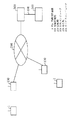
図1は、この発明の実施の形態1における車両空調管理システムの概念図である。図中、車両空調管理システムは、車両に設置された車両空調制御装置1と、路線沿いの複数の地域に設置され、車両空調制御装置1と無線でデータの通信を行なう地域管理局100と、地域管理局100で受信したデータを、インターネット等の回線網200を介して受け、蓄積すると共に解析する管理コンピュータ300と、この管理コンピュータ300と専用線400を介して接続された、車両空調メンテナンス会社に設置されるサービスコンピュータ500とで主に構成されている。
1 is a conceptual diagram of a vehicle air-conditioning management system according to Embodiment 1 of the present invention. In the figure, a vehicle air conditioning management system includes a vehicle air conditioning control device 1 installed in a vehicle, a
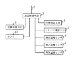
次に、車両空調制御装置1の詳細構成について、図2の構成図に基づき説明する。
車両空調制御装置1は、アンテナ2を備え、地域管理局100との間でのデータの送受信を制御する通信制御手段3を有している。この通信制御手段3には、位置検出手段4から車両の現在の位置情報が、リターン口温度センサ5からリターン口での空気の温度が、壁部温度センサ6から客室の壁部での温度が、車内湿度センサ7から客室の湿度が、外気温度センサ8から外気の温度がそれぞれ定期的に送られてくる。また、空調制御手段9から空調機の稼動情報が、カメラ10からリターン口に配置されたフィルタの映像、室外熱交換器の映像、室内熱交換器の映像が定期的に送られてくる。
なお、位置検出手段4は、車輪の回転数により発駅からの距離を計測し、内部に有する路線図と照会させて、現在の位置を割り出しているが、GPSにより位置を割り出すようにしてもよい。
また、車両空調制御装置1は内部にメモリを有し、送られてくるデータを一時保存させ、1分毎、あるいは、1週間毎に地域管理局100にデータを送信する。
Next, a detailed configuration of the vehicle air conditioning control device 1 will be described based on the configuration diagram of FIG.
The vehicle air-conditioning control device 1 includes an
The position detection means 4 measures the distance from the departure station based on the number of rotations of the wheel, and makes an inquiry with the internal route map to determine the current position. However, the position may be determined by GPS. Good.
Moreover, the vehicle air-conditioning control apparatus 1 has a memory inside, temporarily stores the transmitted data, and transmits the data to the
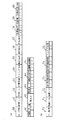
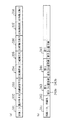
次に、通信制御手段3からアンテナ2を介して送信される送信データのデータフォーマットについて、図3に基づき説明する。
なお、図3(a)は毎分送られる分送信データ、図3(b)は1週間に1回送られる週送信データである。
図3(a)中、分送信データのフォーマットは、先頭より、日・時間50、路線ID51、空調ID52、位置情報53、リターン口温度54、壁部温度55、車内湿度56、外気温度57、保護装置動作状況58、圧縮機動作状況59、冷媒高圧圧力値60、冷媒低圧圧力値61、乗車率62、圧縮機・室外送風機・室内送風機の電流値63、圧縮機吸込温度64、圧縮機吐出温度65の各欄から構成されている。
なお、この車両では、冷媒回路が2系統あるため、保護装置動作状況58、圧縮機動作状況59、冷媒高圧圧力値60、冷媒低圧圧力値61、電流値63、圧縮機吸込温度64、圧縮機吐出温度65は1・2の各系統分の値の欄を有することになる。また、保護装置動作状況58、圧縮機動作状況59、冷媒高圧圧力値60、冷媒低圧圧力値61、乗車率62、電流値63、圧縮機吸込温度64、圧縮機吐出温度65の値は、空調制御手段9より通信制御手段3に送信されたものであり、乗車率62は、車両毎の台車が検知した値を運転室設置の車両モニタを経由して空調制御手段9が受信したものである。
図3(b)中、週送信データのフォーマットは、先頭より、日・時間70、路線ID71、空調ID72、室外熱交換器映像73、室内熱交換器映像74、フィルタ映像75の各欄から構成されている。
なお、既に説明した様に、室外熱交換器映像73、室内熱交換器映像74、フィルタ映像75は、1・2の各系統分の値の欄を有することになる。
Next, a data format of transmission data transmitted from the communication control means 3 via the
3A shows the transmission data sent every minute, and FIG. 3B shows the weekly transmission data sent once a week.
In FIG. 3 (a), the format of the minute transmission data is as follows: date /
In this vehicle, since there are two refrigerant circuits, the protection
In FIG. 3 (b), the format of weekly transmission data is composed of the columns of date /
As already described, the outdoor
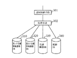
次に、管理コンピュータ300の詳細構成について、図4の構成図に基づき説明する。
管理コンピュータ300は、回線網200を介して行なわれる通信の制御を行なう通信制御手段301と、車両より送られたデータ等に基づき演算・整理等の処理を行なう処理手段302と、車両空調制御装置1から送られたデータを蓄積・保存する第1の空調情報蓄積DB310と、第2の空調情報蓄積DB320と、各車両の設置された車両空調の機器情報を保存する空調機器DB330と、路線毎の情報が保持される路線DB340とから主に構成されている。
Next, the detailed configuration of the
The
次に、各DBのデータフォーマットについて、図5に基づき説明する。
まず、第1の空調情報蓄積DB310のデータフォーマットは、図3(a)の分送信データのデータフォーマットと同じであり、第2の空調情報蓄積DB320のデータフォーマットは、図3(b)の週送信データのデータフォーマットと同じである。
図5(a)は、空調機器DB330のデータフォーマットであり、空調ID331、製造年月日332、空調装置型名333、圧縮機個数334、圧縮機型名335、圧縮機交換日336、送風機個数337、送風機交換日338の各欄から構成されている。
図5(b)は、路線DB340のデータフォーマットであり、路線ID341、路線名342、駅1の情報343、駅2の情報344、駅3の情報345、……の各欄から構成されている。なお、駅の情報の欄は、その路線に存在するn個分存在する。また、駅の情報には、駅名343a、344a、345a、……と位置情報343b、344b、345b、……の2つの欄が存在する。
Next, the data format of each DB will be described with reference to FIG.
First, the data format of the first air conditioning
FIG. 5A shows the data format of the air
FIG. 5B shows the data format of the
次に、上述の構成において、車両空調管理システムの動作について以下に説明する。
<データの送信・蓄積処理>
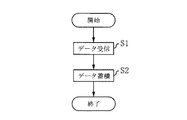
図6は、車両空調管理システムにおけるデータの送信・蓄積の処理を示すフローチャートである。
まず、車両空調管理システムでは、車両空調制御装置1の通信制御手段3が1分毎に分送信データを作成して送信、1週間毎に週送信データを作成して送信し、これらのデータは最寄の地域管理局100、及び回線網200を介して管理コンピュータ300の通信制御手段301に受信され、処理手段302に送られる(ステップ(以下、S)1)。処理手段302では、分送信データであれば、第1の空調情報蓄積DB310に、週送信データであれば、第2の空調情報蓄積DB320に蓄積する(S2)。なお、蓄積においては、それぞれ、日・時間と空調IDとを確認し、同一空調IDのものは、まとめ、かつ、日・時間が順番になるように蓄積している。
Next, the operation of the vehicle air conditioning management system in the above configuration will be described below.
<Data transmission / storage processing>
FIG. 6 is a flowchart showing data transmission / accumulation processing in the vehicle air conditioning management system.
First, in the vehicle air conditioning management system, the communication control means 3 of the vehicle air conditioning control device 1 creates and transmits minute transmission data every minute, and creates and transmits weekly transmission data every week. The data is received by the communication control means 301 of the
<目詰まり判定・メンテナンス計画>
図7は、目詰まり判定・メンテナンス計画の処理を示すフローチャートである。なお、この処理は、週1回、適当な時間に全車両の空調に対して一括して行われる。
まず、第2の空調情報蓄積DB320より、空調ID72毎に、蓄積されている室外熱交換器映像73、室内熱交換器映像74、フィルタ映像75の情報を処理手段302が読み込む(S10)。
次に、各映像を画像解析し、時間に対する汚れの相関関係を求め、清掃等のメンテナンスが必要な時期を計算する(S11)。具体的には、例えば、週毎に蓄積されたフィルタ映像75毎に、フィルタ全体の映像を幾つかの区画に分割し、その区画毎に汚れ具合等を画像処理して数値化し、それを時系列に並べる。これにより、フィルタの各区画での汚れの推移が時系列で分かる。よって、その推移で汚れた場合、将来、いつの時点で空調機の性能が劣化するかを求めることができ、メンテナンスが必要な時期を特定できることになる。
<Clogging detection and maintenance plan>
FIG. 7 is a flowchart showing the clogging determination / maintenance plan process. This process is performed once a week for the air conditioning of all vehicles at an appropriate time.
First, the
Next, each video is image-analyzed, the correlation of dirt with respect to time is obtained, and the time when maintenance such as cleaning is necessary is calculated (S11). Specifically, for example, for each
次に、既に設定されているメンテナンススケジュールの変更の有無を判定する(S12)。例えば、次回のメンテナンス日時が、S11で計算されたメンテナンスが必要な時期よりも後になっていれば、メンテナンススケジュール変更必要(YES)と判定し、そうでなければ不要(NO)と判定する。
S12でメンテナンススケジュール変更と判定された場合には、メンテナンス日時をメンテナンスが必要な時期に変更し(S13)、サービスコンピュータ500に連絡し(S14)、処理を終了する。
車両空調の場合には、路線によって、空気の状況が異なり、フィルタ等の汚れ具体も異なる(例えば、大都市や工場地帯を結ぶ路線では、排気ガスや工場から出る排煙により空気が汚れているのでフィルタの汚れる速度も速く、逆に、山間部等の路線では、空気はきれいであり、フィルタの汚れる速度も遅い)ので、メンテナンスの時期もそれらを考慮して設定しなければならない。本処理では、路線の空調毎に最適なメンテナンス時期を設定できるので、汚れによる処理能力の低下等を未然に防ぐことができる。
Next, it is determined whether there is a change in the maintenance schedule that has already been set (S12). For example, if the next maintenance date / time is later than the time required for the maintenance calculated in S11, it is determined that the maintenance schedule needs to be changed (YES), and otherwise, it is determined that it is unnecessary (NO).
If it is determined in S12 that the maintenance schedule is changed, the maintenance date is changed to a time when maintenance is required (S13), the
In the case of vehicle air conditioning, the air condition differs depending on the route, and the dirt of the filter etc. also varies (for example, on routes connecting large cities and factory zones, the air is dirty due to exhaust gas and exhaust smoke from the factory) Therefore, the speed at which the filter gets dirty is high, and conversely, on routes such as mountainous areas, the air is clean and the speed at which the filter gets dirty is slow), so the maintenance time must also be set in consideration of them. In this process, since an optimal maintenance time can be set for each air conditioning of the route, it is possible to prevent a reduction in processing capacity due to contamination.
なお、ここでは、映像情報を用いて清掃等のメンテナンス時期を調整したが、室内・室外送風機の電流値に基づいて定期メンテナンスの時期を調整するように
してもよい。
図8は、電流値を使用した場合の目詰まり判定・メンテナンス計画の処理を示すフローチャートである。
まず、第1の空調情報蓄積DB310より、空調ID52毎に、蓄積されている電流値63の値を室外送風機、室内送風機毎に読み込み、週間での平均を計算する(S20)。次に、各汚れ具合での各室外送風機、室内送風機での使用電流値を概算し、これとS20で計算した電流値とを比較し、これらの室外送風機、室内送風機で送風される対象となる室外熱交換器、室内熱交換器のだいたいの汚れ具合を判断する(S21)。なお、具体的には、第1の空調情報蓄積DB310から外気温度、壁部温度、リターン口温度、冷媒高圧圧力値、冷媒低圧圧力値等の情報から、全く汚れがなければ必要であったであろう送風量、及び電流値の概算平均値を計算できる。従って、この概算の平均値と実際の電流値とから大体の汚れ具合を計算できる。
Here, the maintenance time for cleaning or the like is adjusted using the video information, but the time for periodic maintenance may be adjusted based on the current value of the indoor / outdoor blower.
FIG. 8 is a flowchart showing the clogging determination / maintenance plan process when the current value is used.
First, from the first air conditioning
次に、既に設定されているメンテナンススケジュールの変更の有無を判定する(S22)。例えば、汚れ具体の値から、あとどの程度でメンテナンスが必要であるかを計算し、スケジュールされたメンテナンス日時が、このメンテナンスが必要な時期よりも後になっていれば、メンテナンススケジュール変更必要(YES)と判定し、そうでなければ不要(NO)と判定する。
S22で、メンテナンススケジュール変更と判定された場合には、メンテナンス日時をメンテナンスが必要な時期に変更し(S23)、サービスコンピュータ500に連絡し(S24)、処理を終了する。
このような方法では、図7の方法に比較して多少精度は落ちるが、高価な画像処理設備が不要となり、比較的安くスケジュール調整が可能になる。
Next, it is determined whether there is a change in the maintenance schedule that has already been set (S22). For example, calculate how much maintenance is required from the specific value of dirt, and if the scheduled maintenance date is later than the time when this maintenance is required, the maintenance schedule needs to be changed (YES) Otherwise, it is determined as unnecessary (NO).
If it is determined in S22 that the maintenance schedule has been changed, the maintenance date is changed to a time when maintenance is required (S23), the
Such a method is somewhat less accurate than the method of FIG. 7, but an expensive image processing facility is not required, and the schedule can be adjusted relatively cheaply.
<回転機経年劣化調査>
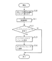
図9は、回転機経年劣化調査の処理を示すフローチャートである。
なお、回転機とは、圧縮機、室内送風機、室外送風機のモータのことである。
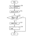
まず、第1の空調情報蓄積DB310より、空調ID72毎に、蓄積されている電流値63の値を室外送風機、室内送風機毎に読み込む(S30)。次に、各電流値の1日毎の平均を計算する(S31)。次に、各編成(一台の列車に接続されている車両、8両編成、10両編成、15両編成等、路線により編成は異なる)毎の各車両(1両目、2両目、3両目、……)に設置された空調機での電流値を比較し、偏差が規定値よりも大きいか小さいかの判定を行う(S32)。ここで、偏差が規定値よりも大きいと判定した場合には、その車両と部品とを特定し、空調機器DBに記録されたデータから一定期間以上使用されていることを確認し(S33)、サービスコンピュータ500に連絡し(S34)、処理を終了する。また、S32で、偏差が小さいと認定された場合には処理を終了させる。なお、S34で、連絡を受けた車両空調メンテナンス会社のサービス要員は、日時を特定し、特定された車両の空調機をメンテナンスすることになる。
このように処理することにより、車両中、経年が進み、さらに、劣化が見られるもののみ交換でき、空調機に対し、異常の発生を未然に防止するとともに、無駄な交換を防止できる。特に、上述の様に、路線によって空調機の負荷が異なるような車両の空調機では、最適な交換時期を把握できることになる。
<Rotary machine aging survey>
FIG. 9 is a flowchart showing the processing of the rotating machine aged deterioration investigation.
In addition, a rotary machine is a motor of a compressor, an indoor air blower, and an outdoor air blower.
First, from the first air conditioning
By processing in this way, it is possible to replace only those that are aged and are deteriorated in the vehicle, and it is possible to prevent the air conditioner from occurring abnormally and to prevent unnecessary replacement. In particular, as described above, in an air conditioner for a vehicle in which the load of the air conditioner varies depending on the route, the optimum replacement time can be grasped.
<ガス漏れ故障診断>
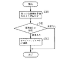
図10は、ガス漏れ故障診断調査の処理を示すフローチャートである。
まず、第1の空調情報蓄積DB310より、空調ID72毎に、蓄積されている最新の圧縮機の電流値63、冷媒高圧圧力値60、冷媒低圧圧力値61を読み込む(S40)。次に、圧縮機の電流値63と予め定めた電流値の基準値、冷媒高圧圧力値60と予め定めた冷媒高圧圧力の基準値、冷媒低圧圧力値61と予め定めた冷媒低圧圧力の基準値を比較し、圧縮機の電流値63が予め定めた電流値の基準値を下回る場合、冷媒高圧圧力値60が予め定めた冷媒高圧圧力の基準値を下回る場合、冷媒低圧圧力値61が予め定めた冷媒低圧圧力の基準値を上回る場合、のいずれかになった場合には、異常であると判定し、サービスコンピュータ500に異常であることを連絡する(S42)。
なお、車両空調メンテナンス会社では、サービスコンピュータ500のモニタに表示された異常情報を確認し、問題の大小により、空調の修理を行なうことになる。
このようにすることで、人手を介さずにサービスコンピュータに異常情報が伝わり、修理等を迅速に行なうことができる。
なお、ここでは、第1の空調情報蓄積DB310からデータを読み込むようにしたが、例えば、車両空調制御装置1から日毎データが送られる毎に、ガス漏れ故障診断を行なうようにすることで、第1の空調情報蓄積DB310への蓄積と同時に処理することも可能となる。
<Gas leak failure diagnosis>
FIG. 10 is a flowchart showing the process of the gas leakage failure diagnosis investigation.
First, the latest accumulated compressor
The vehicle air-conditioning maintenance company confirms the abnormality information displayed on the monitor of the
By doing so, abnormality information is transmitted to the service computer without manual intervention, and repairs and the like can be performed quickly.
Here, the data is read from the first air conditioning
<保護回路動作・故障診断>
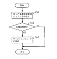
図11は、保護回路動作・故障診断の処理を示すフローチャートである。
まず、第1の空調情報蓄積DB310より、空調ID72毎に、保護装置動作状況58を読み出す(S50)。ここで、保護装置とは、吐出管サーモスタット、インナーサーモスタットのことである。これらは、圧縮機の高温部がある一定以上だと働くものである。また、保護装置が動作している場合には、空調制御装置から送信される保護装置動作状況58には“1”が設定されている。
次に、この保護装置が動作しているか否かを判定する(S51)。これは、保護装置動作状況58が“1”であるか否かで簡単に判定できる。S51で動作中であると判定された場合には、サービスコンピュータ500にガス漏れが発生している可能性があることを連絡する(S52)。
なお、車両空調メンテナンス会社では、サービスコンピュータ500のモニタに表示された情報を確認し、問題が大小により、空調の修理を行なうことになる。
<Protection circuit operation / failure diagnosis>
FIG. 11 is a flowchart showing a protection circuit operation / failure diagnosis process.
First, the protection
Next, it is determined whether or not the protection device is operating (S51). This can be easily determined based on whether or not the protection
The vehicle air-conditioning maintenance company confirms the information displayed on the monitor of the
一般に、空調が必要とする能力は路線により異なるものである。例えば、東北や北海道等の比較的寒い地域の路線は、大きな冷房能力は不用であるが、暖房能力は大きくする必要がある。逆に、九州や四国等の比較的温暖の地域の路線は、大きな冷房能力は必要であるが、暖房能力はそれほど大きくなくてもよい。さらに、大都市を循環する路線で、人の乗車率が大きい路線では、人の体温で車内温度が上がるために大きな冷房能力が必要とされ、人の乗車率が低い山間部の路線では、大きな冷房能力は必要とされない等である。しかし、従来では、それらの状況を細かく調査し、必要に合った空調機の選択や、調整はなされていなかった。
この車両空調管理システムでは、車両空調制御装置1から分毎データを採取しているため、空調の必要能力を画面形式で表示し、把握することができる。
以下に、その方法を説明する。
In general, the capacity required for air conditioning varies depending on the route. For example, routes in relatively cold areas such as Tohoku and Hokkaido do not require a large cooling capacity, but it is necessary to increase the heating capacity. Conversely, routes in relatively warm regions such as Kyushu and Shikoku require a large cooling capacity, but the heating capacity may not be so large. Furthermore, on routes that circulate through large cities, high cooling capacity is required because the temperature inside the vehicle rises due to the temperature of the person, and large routes on mountain routes where the passenger rate is low. The cooling capacity is not required. However, in the past, these situations have been investigated in detail, and the selection and adjustment of air conditioners that suit the needs have not been made.
In this vehicle air-conditioning management system, since the minute data is collected from the vehicle air-conditioning control device 1, the required air-conditioning capacity can be displayed and grasped in a screen format.
The method will be described below.
<路線毎空調状況表示>
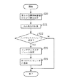
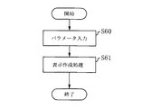
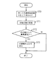
図12は、路線毎空調状況表示処理のフローチャートである。
なお、この処理は、管理者が管理コンピュータ300の画面より、必要項目を入力させることで、空調機の使用割合(負荷状況)を表示させる操作である。
図12中、まず、操作者は調べたい路線の路線ID、対象の日、表示方式のパラメータを入力する(S60)。
この入力は処理手段302に送られ、表示作成処理がなされる(S61)。例えば、S60で、編成毎に空調能力状況を調べたいとして、その表示方式を入力した場合には、S61で、路線IDをキーとして、第1の空調情報蓄積DB310より一致するデータを取り出し、各編成毎に圧縮機の稼動状況(圧縮機動作状況59が“1”の時の時間を、運転全時間で割ったもの)、室外送風機、室内送風機の回転数等を計算し、表示させる。
このようにすることで、路線毎の稼動状況が分かり、空調能力に余裕があるか、それとも、オーバー状況であるかが把握でき、必要にあった能力の空調を選択できる。
<Air conditioning status display for each route>
FIG. 12 is a flowchart of the air conditioning status display process for each route.
This process is an operation for displaying the usage rate (load status) of the air conditioner by allowing the administrator to input necessary items from the screen of the
In FIG. 12, first, the operator inputs a route ID of a route to be examined, a target date, and a display method parameter (S60).
This input is sent to the processing means 302, and display creation processing is performed (S61). For example, if it is desired to check the air conditioning capacity status for each train in S60 and the display method is input, in S61, the matching data is extracted from the first air conditioning
In this way, the operation status for each route can be understood, whether the air conditioning capacity has a margin or whether the air condition is over, and the air conditioning having the required capacity can be selected.
また、例えば、S60で、路線の各位置毎での稼動状況を調べたいとして、その表示方式を入力した場合には、S61で、路線IDをキーとして、第1の空調情報蓄積DB310より一致するデータ(この路線を走った全車両)を取り出し、位置情報がほぼ一致するもの毎に、圧縮機の稼動状況、室外送風機、室内送風機の回転数等の平均を計算し、さらに、路線IDをキーとして、路線DB340より一致するデータを取り出し、駅等を関連つけて計算した結果を表示させる。
このようにすることで、各位置での負荷状況を把握することができる。例えば、A駅から負荷がどんどん上がっているが、C駅からは負荷が下がっている結果から、A駅で急に乗車率が上がって車両内温度が上昇しており、C駅で多くの人が降りてしまい車内温度が低下すること等が把握できる。
Also, for example, if the display method is input to check the operation status at each position of the route at S60, the first air conditioning
By doing in this way, it is possible to grasp the load situation at each position. For example, the load is increasing from station A, but the load is decreasing from station C. As a result, the occupancy rate suddenly increases at station A and the temperature inside the vehicle rises. It is possible to grasp that the temperature inside the vehicle drops and the temperature inside the vehicle decreases.
各車両の空調制御を、管理コンピュータ300で行なうことで、より木目細かい制御が可能になる場合がある。以下に、管理コンピュータ300で、各車両の空調機の制御をする方法について図13のフローチャートに基づき説明する。
まず、第1の空調情報蓄積DB310から、圧縮機吸込温度64と、冷媒低圧圧力値61を読み込む(S70)。次に、この圧縮機吸込温度64と冷媒低圧圧力値61とから冷媒の状態を把握する(S71)。すなわち、圧縮機に吸込まれる冷媒の状態が、過熱蒸気状態か、液状態か、湿り蒸気状態(ガスと液が混ざった状態)かである。次に、冷媒の状態が所定値以上に過熱蒸気状態になっているか否かを判定し(S72)、なっている場合には処理を終了、なっていなければ、空調機を停止させるための信号を回線網200を介して車両空調制御装置1に送信する(S73)。
また、この判定では、例えば、圧縮機吐出温度65と冷媒高圧圧力値60とから冷媒の状態を把握することも可能である。
When the air conditioning control of each vehicle is performed by the
First, the
In this determination, for example, the state of the refrigerant can be grasped from the
また、路線での電車の位置情報に基づいて、空調機の動作を制御することも可能である。
例えば、分毎に送られてくる分送信データの位置情報53を確認し、多くの客が乗り込むA駅に近づいてきたと認識した場合には、管理コンピュータ300から車両空調制御装置1に圧縮機の回転数の増加、各送風機の回転数を増加させる信号を送って冷房能力を上げ、多くの客が降りてしまうC駅に近づいてきたと認識した場合には、管理コンピュータ300から車両空調制御装置1に圧縮機の回転数の減少、各送風機の回転数を減少させる信号を送って冷房能力を下げる。
これにより、車両内の負荷を事前に予想し、より快適な空調を乗客に提供できる。
It is also possible to control the operation of the air conditioner based on the position information of the train on the route.
For example, if the
Thereby, the load in a vehicle can be estimated in advance and a more comfortable air conditioning can be provided to a passenger.
1 車両空調制御装置、 2 アンテナ、 3 通信制御手段、
4 位置検出手段、 5 リターン口温度センサ、 6 壁部温度センサ、
7 車内湿度センサ、 8 外気温度センサ、 9 空調制御手段、
10 カメラ、100 地域管理局、 200 回線網、
300 管理コンピュータ、 301 通信制御手段、 302 処理手段、
310 第1の空調情報蓄積DB、 320 第2の空調情報蓄積DB、
330 空調機器DB、 340 路線DB、 400 専用線、
500 サービスコンピュータ。
1 vehicle air-conditioning control device, 2 antenna, 3 communication control means,
4 position detection means, 5 return port temperature sensor, 6 wall temperature sensor,
7 In-vehicle humidity sensor, 8 Outside air temperature sensor, 9 Air conditioning control means,
10 cameras, 100 regional management stations, 200 network,
300 management computer, 301 communication control means, 302 processing means,
310 1st air conditioning information accumulation DB, 320 2nd air conditioning information accumulation DB,
330 Air Conditioning Equipment DB, 340 Route DB, 400 Dedicated Line,
500 Service computer.
Claims (2)
前記車両空調制御装置から送信されたデータを蓄積する空調情報蓄積データベースを有した管理コンピュータを備え、
前記管理コンピュータは、前記空調情報蓄積データベースから路線毎に前記データを取出し、前記車両の位置情報がほぼ一致するもの毎に前記空調機の運転情報の平均を計算し、計算した結果から前記空調機の負荷が上がる位置と前記空調機の負荷が下がる位置を求め、
前記車両が前記空調機の負荷が上がる位置に近づくと前記空調機の能力を上げる若しくは前記空調機の負荷が下がる位置に近づくと前記空調機の能力を下げるための信号を前記車両空調制御装置に送信する
ことを特徴とする車両空調制御システム。 A vehicle air-conditioning control device that is installed in a vehicle of a plurality of trains and periodically transmits data having operation information of the air conditioner mounted on the vehicle and position information of the vehicle;
A management computer having an air conditioning information accumulation database for accumulating data transmitted from the vehicle air conditioning control device;
The management computer extracts the data for each route from the air conditioning information accumulation database , calculates an average of the operation information of the air conditioner for each of the vehicles whose position information is substantially the same , and calculates the air conditioner from the calculated result. Find the position where the load of the air conditioner increases and the position where the load of the air conditioner decreases,
When the vehicle approaches a position where the load of the air conditioner increases, a signal for increasing the capacity of the air conditioner or a signal for decreasing the capacity of the air conditioner when approaching a position where the load of the air conditioner decreases is sent to the vehicle air conditioning control device. Send
A vehicle air-conditioning control system.
ことを特徴とする請求項1に記載の車両空調制御システム。 The management computer has a route database that accumulates station information for each route, and displays the calculation result in association with a position where the load of the air conditioner increases and a position where the load of the air conditioner decreases. The vehicle air conditioning control system according to claim 1 .
Priority Applications (1)
| Application Number | Priority Date | Filing Date | Title |
|---|---|---|---|
| JP2008268651A JP5040887B2 (en) | 2008-10-17 | 2008-10-17 | Vehicle air conditioning management system |
Applications Claiming Priority (1)
| Application Number | Priority Date | Filing Date | Title |
|---|---|---|---|
| JP2008268651A JP5040887B2 (en) | 2008-10-17 | 2008-10-17 | Vehicle air conditioning management system |
Related Parent Applications (1)
| Application Number | Title | Priority Date | Filing Date |
|---|---|---|---|
| JP2003089733A Division JP4244676B2 (en) | 2003-03-28 | 2003-03-28 | Vehicle air conditioning management system |
Publications (2)
| Publication Number | Publication Date |
|---|---|
| JP2009007006A JP2009007006A (en) | 2009-01-15 |
| JP5040887B2 true JP5040887B2 (en) | 2012-10-03 |
Family
ID=40322508
Family Applications (1)
| Application Number | Title | Priority Date | Filing Date |
|---|---|---|---|
| JP2008268651A Expired - Fee Related JP5040887B2 (en) | 2008-10-17 | 2008-10-17 | Vehicle air conditioning management system |
Country Status (1)
| Country | Link |
|---|---|
| JP (1) | JP5040887B2 (en) |
Families Citing this family (6)
| Publication number | Priority date | Publication date | Assignee | Title |
|---|---|---|---|---|
| US8892277B2 (en) | 2009-07-22 | 2014-11-18 | Mitsubishi Electric Corporation | Vehicle air-conditioning control method |
| JP5742208B2 (en) * | 2010-12-21 | 2015-07-01 | 日本電気株式会社 | Vehicle air conditioning control system, vehicle air conditioning control device, vehicle air conditioning control method and program |
| JP5679835B2 (en) * | 2011-01-21 | 2015-03-04 | 三菱電機株式会社 | Vehicle air conditioner and vehicle |
| JP5868135B2 (en) * | 2011-11-17 | 2016-02-24 | 三菱電機株式会社 | Air conditioner for vehicles |
| KR101404785B1 (en) | 2012-09-10 | 2014-06-12 | 주식회사 에스에이치에이치(Shh) | Remote Air Control System of Train |
| CN109219552B (en) * | 2016-06-10 | 2021-04-13 | 三菱电机株式会社 | Vehicle air conditioner and abnormality detection system for vehicle air conditioner |
Family Cites Families (8)
| Publication number | Priority date | Publication date | Assignee | Title |
|---|---|---|---|---|
| JPS5924614U (en) * | 1982-08-09 | 1984-02-15 | 三菱電機株式会社 | Vehicle air conditioner |
| JPH0664536A (en) * | 1992-08-21 | 1994-03-08 | Mitsubishi Electric Corp | Vehicle cooling control device |
| JP3305957B2 (en) * | 1996-09-05 | 2002-07-24 | 株式会社東芝 | Train inspection / train failure recovery support device |
| JPH1120688A (en) * | 1997-06-30 | 1999-01-26 | Mitsubishi Electric Corp | Air conditioner for vehicle |
| JP3387000B2 (en) * | 1998-02-13 | 2003-03-17 | 株式会社日立製作所 | Air conditioner monitoring system and remote monitoring device |
| JP2001030903A (en) * | 1999-07-23 | 2001-02-06 | Fuji Electric Co Ltd | Electric railcar operation data collecting system |
| JP3494158B2 (en) * | 2000-09-06 | 2004-02-03 | 株式会社日立製作所 | Air conditioner management system and conversion device used therefor |
| JP2002284005A (en) * | 2001-03-27 | 2002-10-03 | Mitsubishi Electric Corp | Air conditioning controller for railroad rolling stock and air conditioning control information collection system for railroad rolling stock |
-
2008
- 2008-10-17 JP JP2008268651A patent/JP5040887B2/en not_active Expired - Fee Related
Also Published As
| Publication number | Publication date |
|---|---|
| JP2009007006A (en) | 2009-01-15 |
Similar Documents
| Publication | Publication Date | Title |
|---|---|---|
| JP5274555B2 (en) | Vehicle air conditioner, vehicle air conditioning management system, and vehicle air conditioning management method | |
| JP5040887B2 (en) | Vehicle air conditioning management system | |
| JP4244676B2 (en) | Vehicle air conditioning management system | |
| JP5471763B2 (en) | AIR CONDITIONER, DEVICE SYSTEM, INFORMATION MANAGEMENT SYSTEM, AND AIR CONDITIONER CONTROL METHOD | |
| US20220147949A1 (en) | Systems and methods for automated diagnostics of hvac systems | |
| JP2008232531A (en) | Remote performance monitoring device and method | |
| JP6639666B2 (en) | Vehicle air conditioner and clogging detection system for vehicle air conditioner | |
| JP2013213669A (en) | Equipment system | |
| JP6591066B2 (en) | Air conditioning management system for railway vehicles | |
| AU2020222538B2 (en) | Device Management System | |
| EP3214384B1 (en) | Remote controller for air conditioning system | |
| JP2024038458A (en) | Air conditioner support system | |
| US7599816B2 (en) | Maintenance-information providing system | |
| WO2020105454A1 (en) | Failure analysis system and failure analysis device | |
| JP4387757B2 (en) | Air conditioner data providing system and air conditioner data providing method | |
| JP6180094B2 (en) | On-vehicle monitoring device, ground equipment, and vehicle air conditioning system | |
| US10663936B2 (en) | Remote clear of an HVAC system | |
| JP4550253B2 (en) | Remote monitoring system for air conditioner and monitoring method for indoor unit | |
| JP5679712B2 (en) | Vehicle equipment control device | |
| JP2020123262A (en) | Service proposal time adjusting device and air conditioning system | |
| JP5959182B2 (en) | Vehicle equipment control device and vehicle air conditioning management system | |
| JP2020122640A (en) | Maintenance timing adjusting device and air conditioning system | |
| WO2023135722A1 (en) | Equipment management device, equipment management system, and data processing method for equipment management system | |
| WO2023170780A1 (en) | Component diagnosis device, component diagnosis system, method for diagnosing component of air conditioner, component inventory management system, and component inventory management method | |
| WO2022185356A1 (en) | Air conditioning data processor and air conditioner management system |
Legal Events
| Date | Code | Title | Description |
|---|---|---|---|
| A621 | Written request for application examination |
Free format text: JAPANESE INTERMEDIATE CODE: A621 Effective date: 20081017 |
|
| A977 | Report on retrieval |
Free format text: JAPANESE INTERMEDIATE CODE: A971007 Effective date: 20110224 |
|
| A131 | Notification of reasons for refusal |
Free format text: JAPANESE INTERMEDIATE CODE: A131 Effective date: 20110322 |
|
| A521 | Request for written amendment filed |
Free format text: JAPANESE INTERMEDIATE CODE: A523 Effective date: 20110427 |
|
| A131 | Notification of reasons for refusal |
Free format text: JAPANESE INTERMEDIATE CODE: A131 Effective date: 20111101 |
|
| A521 | Request for written amendment filed |
Free format text: JAPANESE INTERMEDIATE CODE: A523 Effective date: 20111222 |
|
| TRDD | Decision of grant or rejection written | ||
| A01 | Written decision to grant a patent or to grant a registration (utility model) |
Free format text: JAPANESE INTERMEDIATE CODE: A01 Effective date: 20120612 |
|
| A01 | Written decision to grant a patent or to grant a registration (utility model) |
Free format text: JAPANESE INTERMEDIATE CODE: A01 |
|
| A61 | First payment of annual fees (during grant procedure) |
Free format text: JAPANESE INTERMEDIATE CODE: A61 Effective date: 20120625 |
|
| R151 | Written notification of patent or utility model registration |
Ref document number: 5040887 Country of ref document: JP Free format text: JAPANESE INTERMEDIATE CODE: R151 |
|
| FPAY | Renewal fee payment (event date is renewal date of database) |
Free format text: PAYMENT UNTIL: 20150720 Year of fee payment: 3 |
|
| R250 | Receipt of annual fees |
Free format text: JAPANESE INTERMEDIATE CODE: R250 |
|
| R250 | Receipt of annual fees |
Free format text: JAPANESE INTERMEDIATE CODE: R250 |
|
| R250 | Receipt of annual fees |
Free format text: JAPANESE INTERMEDIATE CODE: R250 |
|
| R250 | Receipt of annual fees |
Free format text: JAPANESE INTERMEDIATE CODE: R250 |
|
| R250 | Receipt of annual fees |
Free format text: JAPANESE INTERMEDIATE CODE: R250 |
|
| R250 | Receipt of annual fees |
Free format text: JAPANESE INTERMEDIATE CODE: R250 |
|
| R250 | Receipt of annual fees |
Free format text: JAPANESE INTERMEDIATE CODE: R250 |
|
| LAPS | Cancellation because of no payment of annual fees |