EP1945094B1 - Imagerie fluorescente codee par frequence et par spectre - Google Patents
Imagerie fluorescente codee par frequence et par spectre Download PDFInfo
- Publication number
- EP1945094B1 EP1945094B1 EP06826125.4A EP06826125A EP1945094B1 EP 1945094 B1 EP1945094 B1 EP 1945094B1 EP 06826125 A EP06826125 A EP 06826125A EP 1945094 B1 EP1945094 B1 EP 1945094B1
- Authority
- EP
- European Patent Office
- Prior art keywords
- radiation
- arrangement
- sample
- exemplary
- radiations
- Prior art date
- Legal status (The legal status is an assumption and is not a legal conclusion. Google has not performed a legal analysis and makes no representation as to the accuracy of the status listed.)
- Active
Links
- 238000000799 fluorescence microscopy Methods 0.000 title description 10
- 239000000835 fiber Substances 0.000 claims description 57
- 230000005855 radiation Effects 0.000 claims description 48
- 238000000034 method Methods 0.000 claims description 44
- 239000013307 optical fiber Substances 0.000 claims description 17
- 238000005424 photoluminescence Methods 0.000 claims description 17
- 238000005253 cladding Methods 0.000 claims description 6
- 230000009977 dual effect Effects 0.000 claims description 6
- 238000012545 processing Methods 0.000 claims description 6
- 239000000523 sample Substances 0.000 description 60
- 238000010586 diagram Methods 0.000 description 24
- 238000005286 illumination Methods 0.000 description 19
- 238000003384 imaging method Methods 0.000 description 18
- 230000003595 spectral effect Effects 0.000 description 18
- 230000005284 excitation Effects 0.000 description 16
- 238000012937 correction Methods 0.000 description 12
- 238000000695 excitation spectrum Methods 0.000 description 11
- 230000033001 locomotion Effects 0.000 description 8
- 238000001228 spectrum Methods 0.000 description 8
- IAZDPXIOMUYVGZ-UHFFFAOYSA-N Dimethylsulphoxide Chemical compound CS(C)=O IAZDPXIOMUYVGZ-UHFFFAOYSA-N 0.000 description 6
- 238000001839 endoscopy Methods 0.000 description 6
- 238000005259 measurement Methods 0.000 description 6
- 230000008901 benefit Effects 0.000 description 5
- 238000001218 confocal laser scanning microscopy Methods 0.000 description 5
- 238000004624 confocal microscopy Methods 0.000 description 5
- 230000001419 dependent effect Effects 0.000 description 5
- 239000006185 dispersion Substances 0.000 description 5
- 238000010521 absorption reaction Methods 0.000 description 4
- 238000001514 detection method Methods 0.000 description 4
- 238000002073 fluorescence micrograph Methods 0.000 description 4
- 230000003287 optical effect Effects 0.000 description 4
- 241000699666 Mus <mouse, genus> Species 0.000 description 3
- 230000005540 biological transmission Effects 0.000 description 3
- 238000000295 emission spectrum Methods 0.000 description 3
- MHMNJMPURVTYEJ-UHFFFAOYSA-N fluorescein-5-isothiocyanate Chemical compound O1C(=O)C2=CC(N=C=S)=CC=C2C21C1=CC=C(O)C=C1OC1=CC(O)=CC=C21 MHMNJMPURVTYEJ-UHFFFAOYSA-N 0.000 description 3
- 238000012014 optical coherence tomography Methods 0.000 description 3
- 238000011160 research Methods 0.000 description 3
- 238000009987 spinning Methods 0.000 description 3
- 230000004075 alteration Effects 0.000 description 2
- 230000007812 deficiency Effects 0.000 description 2
- 230000000694 effects Effects 0.000 description 2
- 238000005516 engineering process Methods 0.000 description 2
- 238000012632 fluorescent imaging Methods 0.000 description 2
- 239000005090 green fluorescent protein Substances 0.000 description 2
- CPBQJMYROZQQJC-UHFFFAOYSA-N helium neon Chemical compound [He].[Ne] CPBQJMYROZQQJC-UHFFFAOYSA-N 0.000 description 2
- 238000001727 in vivo Methods 0.000 description 2
- MOFVSTNWEDAEEK-UHFFFAOYSA-M indocyanine green Chemical compound [Na+].[O-]S(=O)(=O)CCCCN1C2=CC=C3C=CC=CC3=C2C(C)(C)C1=CC=CC=CC=CC1=[N+](CCCCS([O-])(=O)=O)C2=CC=C(C=CC=C3)C3=C2C1(C)C MOFVSTNWEDAEEK-UHFFFAOYSA-M 0.000 description 2
- 229960004657 indocyanine green Drugs 0.000 description 2
- 238000012771 intravital microscopy Methods 0.000 description 2
- 230000004089 microcirculation Effects 0.000 description 2
- 230000004048 modification Effects 0.000 description 2
- 238000012986 modification Methods 0.000 description 2
- 230000010363 phase shift Effects 0.000 description 2
- 239000004038 photonic crystal Substances 0.000 description 2
- 238000011084 recovery Methods 0.000 description 2
- 238000005316 response function Methods 0.000 description 2
- 238000004611 spectroscopical analysis Methods 0.000 description 2
- -1 ASE source Substances 0.000 description 1
- 102000012406 Carcinoembryonic Antigen Human genes 0.000 description 1
- 108010022366 Carcinoembryonic Antigen Proteins 0.000 description 1
- YZCKVEUIGOORGS-OUBTZVSYSA-N Deuterium Chemical compound [2H] YZCKVEUIGOORGS-OUBTZVSYSA-N 0.000 description 1
- 102000004190 Enzymes Human genes 0.000 description 1
- 108090000790 Enzymes Proteins 0.000 description 1
- 108010043121 Green Fluorescent Proteins Proteins 0.000 description 1
- 102000004144 Green Fluorescent Proteins Human genes 0.000 description 1
- 241001465754 Metazoa Species 0.000 description 1
- 241000699670 Mus sp. Species 0.000 description 1
- 206010028980 Neoplasm Diseases 0.000 description 1
- 208000007479 Orofaciodigital syndrome type 1 Diseases 0.000 description 1
- 206010061535 Ovarian neoplasm Diseases 0.000 description 1
- 108091005804 Peptidases Proteins 0.000 description 1
- 239000004365 Protease Substances 0.000 description 1
- 102100037486 Reverse transcriptase/ribonuclease H Human genes 0.000 description 1
- 208000005718 Stomach Neoplasms Diseases 0.000 description 1
- 238000000862 absorption spectrum Methods 0.000 description 1
- 238000013459 approach Methods 0.000 description 1
- 230000009286 beneficial effect Effects 0.000 description 1
- 229920001222 biopolymer Polymers 0.000 description 1
- 238000004364 calculation method Methods 0.000 description 1
- 210000004027 cell Anatomy 0.000 description 1
- 230000008859 change Effects 0.000 description 1
- 210000003040 circulating cell Anatomy 0.000 description 1
- 238000010226 confocal imaging Methods 0.000 description 1
- 238000007796 conventional method Methods 0.000 description 1
- 230000008878 coupling Effects 0.000 description 1
- 238000010168 coupling process Methods 0.000 description 1
- 238000005859 coupling reaction Methods 0.000 description 1
- 239000013078 crystal Substances 0.000 description 1
- 230000003247 decreasing effect Effects 0.000 description 1
- 230000007123 defense Effects 0.000 description 1
- 229910052805 deuterium Inorganic materials 0.000 description 1
- 238000011161 development Methods 0.000 description 1
- 238000003745 diagnosis Methods 0.000 description 1
- 238000002059 diagnostic imaging Methods 0.000 description 1
- 201000010099 disease Diseases 0.000 description 1
- 208000037265 diseases, disorders, signs and symptoms Diseases 0.000 description 1
- 239000000975 dye Substances 0.000 description 1
- 238000001914 filtration Methods 0.000 description 1
- 238000002189 fluorescence spectrum Methods 0.000 description 1
- 239000007850 fluorescent dye Substances 0.000 description 1
- 238000009615 fourier-transform spectroscopy Methods 0.000 description 1
- 206010017758 gastric cancer Diseases 0.000 description 1
- 230000014509 gene expression Effects 0.000 description 1
- 229910052736 halogen Inorganic materials 0.000 description 1
- 230000036541 health Effects 0.000 description 1
- 238000000338 in vitro Methods 0.000 description 1
- 238000011503 in vivo imaging Methods 0.000 description 1
- 238000002372 labelling Methods 0.000 description 1
- 239000011159 matrix material Substances 0.000 description 1
- 230000007246 mechanism Effects 0.000 description 1
- QSHDDOUJBYECFT-UHFFFAOYSA-N mercury Chemical compound [Hg] QSHDDOUJBYECFT-UHFFFAOYSA-N 0.000 description 1
- 229910052753 mercury Inorganic materials 0.000 description 1
- 238000001000 micrograph Methods 0.000 description 1
- 238000000386 microscopy Methods 0.000 description 1
- 239000003607 modifier Substances 0.000 description 1
- 238000012544 monitoring process Methods 0.000 description 1
- 210000003205 muscle Anatomy 0.000 description 1
- 230000007935 neutral effect Effects 0.000 description 1
- 239000005304 optical glass Substances 0.000 description 1
- 201000003455 orofaciodigital syndrome I Diseases 0.000 description 1
- 230000010287 polarization Effects 0.000 description 1
- 229920000435 poly(dimethylsiloxane) Polymers 0.000 description 1
- 238000012805 post-processing Methods 0.000 description 1
- 108090000765 processed proteins & peptides Proteins 0.000 description 1
- 229910052761 rare earth metal Inorganic materials 0.000 description 1
- 150000002910 rare earth metals Chemical class 0.000 description 1
- 238000000985 reflectance spectrum Methods 0.000 description 1
- 239000004065 semiconductor Substances 0.000 description 1
- 238000000926 separation method Methods 0.000 description 1
- 201000011549 stomach cancer Diseases 0.000 description 1
- 230000009466 transformation Effects 0.000 description 1
- 238000013519 translation Methods 0.000 description 1
- 238000000482 two photon fluorescence microscopy Methods 0.000 description 1
- 230000002792 vascular Effects 0.000 description 1
- 210000005166 vasculature Anatomy 0.000 description 1
- XLYOFNOQVPJJNP-UHFFFAOYSA-N water Substances O XLYOFNOQVPJJNP-UHFFFAOYSA-N 0.000 description 1
- 229910052724 xenon Inorganic materials 0.000 description 1
- FHNFHKCVQCLJFQ-UHFFFAOYSA-N xenon atom Chemical compound [Xe] FHNFHKCVQCLJFQ-UHFFFAOYSA-N 0.000 description 1
Images


Classifications
-
- A—HUMAN NECESSITIES
- A61—MEDICAL OR VETERINARY SCIENCE; HYGIENE
- A61B—DIAGNOSIS; SURGERY; IDENTIFICATION
- A61B5/00—Measuring for diagnostic purposes; Identification of persons
- A61B5/0059—Measuring for diagnostic purposes; Identification of persons using light, e.g. diagnosis by transillumination, diascopy, fluorescence
- A61B5/0071—Measuring for diagnostic purposes; Identification of persons using light, e.g. diagnosis by transillumination, diascopy, fluorescence by measuring fluorescence emission
-
- A—HUMAN NECESSITIES
- A61—MEDICAL OR VETERINARY SCIENCE; HYGIENE
- A61B—DIAGNOSIS; SURGERY; IDENTIFICATION
- A61B1/00—Instruments for performing medical examinations of the interior of cavities or tubes of the body by visual or photographical inspection, e.g. endoscopes; Illuminating arrangements therefor
- A61B1/04—Instruments for performing medical examinations of the interior of cavities or tubes of the body by visual or photographical inspection, e.g. endoscopes; Illuminating arrangements therefor combined with photographic or television appliances
- A61B1/043—Instruments for performing medical examinations of the interior of cavities or tubes of the body by visual or photographical inspection, e.g. endoscopes; Illuminating arrangements therefor combined with photographic or television appliances for fluorescence imaging
-
- A—HUMAN NECESSITIES
- A61—MEDICAL OR VETERINARY SCIENCE; HYGIENE
- A61B—DIAGNOSIS; SURGERY; IDENTIFICATION
- A61B1/00—Instruments for performing medical examinations of the interior of cavities or tubes of the body by visual or photographical inspection, e.g. endoscopes; Illuminating arrangements therefor
- A61B1/06—Instruments for performing medical examinations of the interior of cavities or tubes of the body by visual or photographical inspection, e.g. endoscopes; Illuminating arrangements therefor with illuminating arrangements
- A61B1/07—Instruments for performing medical examinations of the interior of cavities or tubes of the body by visual or photographical inspection, e.g. endoscopes; Illuminating arrangements therefor with illuminating arrangements using light-conductive means, e.g. optical fibres
-
- A—HUMAN NECESSITIES
- A61—MEDICAL OR VETERINARY SCIENCE; HYGIENE
- A61B—DIAGNOSIS; SURGERY; IDENTIFICATION
- A61B5/00—Measuring for diagnostic purposes; Identification of persons
- A61B5/0059—Measuring for diagnostic purposes; Identification of persons using light, e.g. diagnosis by transillumination, diascopy, fluorescence
- A61B5/0075—Measuring for diagnostic purposes; Identification of persons using light, e.g. diagnosis by transillumination, diascopy, fluorescence by spectroscopy, i.e. measuring spectra, e.g. Raman spectroscopy, infrared absorption spectroscopy
-
- A—HUMAN NECESSITIES
- A61—MEDICAL OR VETERINARY SCIENCE; HYGIENE
- A61B—DIAGNOSIS; SURGERY; IDENTIFICATION
- A61B5/00—Measuring for diagnostic purposes; Identification of persons
- A61B5/0059—Measuring for diagnostic purposes; Identification of persons using light, e.g. diagnosis by transillumination, diascopy, fluorescence
- A61B5/0082—Measuring for diagnostic purposes; Identification of persons using light, e.g. diagnosis by transillumination, diascopy, fluorescence adapted for particular medical purposes
- A61B5/0084—Measuring for diagnostic purposes; Identification of persons using light, e.g. diagnosis by transillumination, diascopy, fluorescence adapted for particular medical purposes for introduction into the body, e.g. by catheters
-
- G—PHYSICS
- G01—MEASURING; TESTING
- G01N—INVESTIGATING OR ANALYSING MATERIALS BY DETERMINING THEIR CHEMICAL OR PHYSICAL PROPERTIES
- G01N21/00—Investigating or analysing materials by the use of optical means, i.e. using sub-millimetre waves, infrared, visible or ultraviolet light
- G01N21/62—Systems in which the material investigated is excited whereby it emits light or causes a change in wavelength of the incident light
- G01N21/63—Systems in which the material investigated is excited whereby it emits light or causes a change in wavelength of the incident light optically excited
- G01N21/64—Fluorescence; Phosphorescence
- G01N21/6408—Fluorescence; Phosphorescence with measurement of decay time, time resolved fluorescence
-
- G—PHYSICS
- G01—MEASURING; TESTING
- G01N—INVESTIGATING OR ANALYSING MATERIALS BY DETERMINING THEIR CHEMICAL OR PHYSICAL PROPERTIES
- G01N21/00—Investigating or analysing materials by the use of optical means, i.e. using sub-millimetre waves, infrared, visible or ultraviolet light
- G01N21/62—Systems in which the material investigated is excited whereby it emits light or causes a change in wavelength of the incident light
- G01N21/63—Systems in which the material investigated is excited whereby it emits light or causes a change in wavelength of the incident light optically excited
- G01N21/64—Fluorescence; Phosphorescence
- G01N21/645—Specially adapted constructive features of fluorimeters
- G01N21/6456—Spatial resolved fluorescence measurements; Imaging
- G01N21/6458—Fluorescence microscopy
-
- A—HUMAN NECESSITIES
- A61—MEDICAL OR VETERINARY SCIENCE; HYGIENE
- A61B—DIAGNOSIS; SURGERY; IDENTIFICATION
- A61B5/00—Measuring for diagnostic purposes; Identification of persons
- A61B5/0059—Measuring for diagnostic purposes; Identification of persons using light, e.g. diagnosis by transillumination, diascopy, fluorescence
- A61B5/0062—Arrangements for scanning
- A61B5/0066—Optical coherence imaging
-
- A—HUMAN NECESSITIES
- A61—MEDICAL OR VETERINARY SCIENCE; HYGIENE
- A61B—DIAGNOSIS; SURGERY; IDENTIFICATION
- A61B5/00—Measuring for diagnostic purposes; Identification of persons
- A61B5/72—Signal processing specially adapted for physiological signals or for diagnostic purposes
- A61B5/7235—Details of waveform analysis
- A61B5/7253—Details of waveform analysis characterised by using transforms
- A61B5/7257—Details of waveform analysis characterised by using transforms using Fourier transforms
-
- G—PHYSICS
- G01—MEASURING; TESTING
- G01N—INVESTIGATING OR ANALYSING MATERIALS BY DETERMINING THEIR CHEMICAL OR PHYSICAL PROPERTIES
- G01N21/00—Investigating or analysing materials by the use of optical means, i.e. using sub-millimetre waves, infrared, visible or ultraviolet light
- G01N21/62—Systems in which the material investigated is excited whereby it emits light or causes a change in wavelength of the incident light
- G01N21/63—Systems in which the material investigated is excited whereby it emits light or causes a change in wavelength of the incident light optically excited
- G01N21/64—Fluorescence; Phosphorescence
- G01N2021/6417—Spectrofluorimetric devices
- G01N2021/6419—Excitation at two or more wavelengths
-
- G—PHYSICS
- G01—MEASURING; TESTING
- G01N—INVESTIGATING OR ANALYSING MATERIALS BY DETERMINING THEIR CHEMICAL OR PHYSICAL PROPERTIES
- G01N21/00—Investigating or analysing materials by the use of optical means, i.e. using sub-millimetre waves, infrared, visible or ultraviolet light
- G01N21/62—Systems in which the material investigated is excited whereby it emits light or causes a change in wavelength of the incident light
- G01N21/63—Systems in which the material investigated is excited whereby it emits light or causes a change in wavelength of the incident light optically excited
- G01N21/64—Fluorescence; Phosphorescence
- G01N2021/6417—Spectrofluorimetric devices
- G01N2021/6421—Measuring at two or more wavelengths
Definitions
- the present invention generally relates to arrangements and methods for facilitating photoluminescence imaging, and particularly for, e.g., obtaining fluorescence images via endoscopes, catheters, or small-diameter probes.
- FITC Fluorescein Isothiocyanate
- An 800 ⁇ m diameter endoscope with 10,000 optical fibers which can be used with Cy5.5 and Cy7, excited at 673 nm can also be utilized.
- the imaging tip which has a 56° field of view in water, can also facilitate white light reflectance imaging with a resolution of 7 line pairs per millimeter, as determined with an USAF 1951 resolution target. Exemplary images were presented from mouse vasculature and of protease activity in an ovarian tumor with rates ranging from 3 to 10 Hz. (See M. A.
- Spectral encoding has been previously demonstrated for reflectance imaging. (See G. J. Tearney et al., "Spectrally encoded confocal microscopy,” Opt. Lett., Vol. 23(15), 1152 (1998 ); and G. J. Tearney et al., “Spectrally encoded miniature endoscopy,” Optics Letters, Vol. 27(6), 412 (2002 )).
- broadband light from an optical fiber may be dispersed by a grating, and focused onto a line on the sample. In this matter, the image does not have to be scanned in this dimension.
- a reflected light returns through the lens, grating, and optical fiber and the spectrally encoded image is then decoded via heterodyne Fourier transform spectroscopy (see G. J. Tearney et al., "Spectrally encoded confocal microscopy,” Opt. Lett., Vol. 23(15), 1152 (1998 )) or with another grating in conjunction with a CCD detector (see G. J. Tearney et al., “Spectrally encoded miniature endoscopy,” Optics Letters, Vol. 27(6), 412 (2002 )).
- the transverse dimension can then be scanned by, for example, rotating the fiber and distal optics, which can be implemented in small diameter probes.
- the number of resolvable points (n) along one spectrally encoded line can be determined by the spectral bandwidth ( ⁇ ), center wavelength ( ⁇ 0 ), beam diameter (d), and grating: n ⁇ ⁇ ⁇ d G ⁇ 0 cos ⁇ i , where G and ⁇ i are the grating groove density and incidence angle, respectively.
- the spectrally encoded photoluminescient techniques are generally based on a similar concept.
- the fluorescence emission may be Stokes shifted, and the spatial locations are generally no longer uniquely related to the detected wavelengths.
- spectroscopic methods and arrangements implementing the same may not be effective for decoding the image.
- a spectral-and-frequency-encoded ("SFE") imaging techniques can utilize a wavelength-dependent frequency modulation of the excitation light before it is dispersed onto the sample via the grating.
- the fluorescence emission at each location can therefore be modulated in concert with the frequency of the excitation light, thereby producing an additional level of encoding.
- the reference interferometer signal could be used for active feedback control to correct non-linear movement of the scanning mirrors, thereby eliminating the need for post-acquisition processing.
- One of the objectives of the present invention is to overcome certain deficiencies and shortcomings of the prior art arrangements and methods (including those described herein above), and provide exemplary embodiments of arrangements and methods for facilitating photoluminescence imaging, e.g., to obtain fluorescence images via endoscopes, catheters, or small-diameter probes.
- the arrangements and methods for fluorescent imaging e.g., spectrally and frequency encoded ("SFE") fluorescence imaging, can be provided, which can be performed in a sub-millimeter diameter endoscope with a high number of resolvable points.
- SFE spectrally and frequency encoded
- a high number of resolvable points may be obtained within a small diameter probe, since the excitation bandwidth and the grating groove density govern the number of points in the image.
- the number of resolvable points attained by SFE is affected by the excitation spectra of the fluorophore.
- Table 1 depicts the predicted number of resolvable points for several common fluorescent labels, assuming beam diameters of 1.0 and 0.5 mm and a grating groove density of 1500 lines/mm. For each case, the theoretical number of resolvable points either equals or exceeds that of fiber bundles of comparable diameter.
- an exemplary spectral encoding technique can be utilized for fluorescence imaging using a swept source laser.
- the laser wavelengths can be rapidly tuned over the absorption band of the fluorophore. Each wavelength can be dispersed to a different location on the sample. The collected sample fluorescence can then be decoded as a function of time to reconstruct the image.
- a reference interferometer signal can be used for active feedback control to correct non-linear movement of the scanning mirrors, thereby eliminating the need for post-acquisition processing.
- systems and methods can be provided for obtaining a photoluminescence radiation from at least one portion of a sample.
- a photoluminescence radiation from at least one portion of a sample.
- the second and third radiations can be provided to different locations of the portion.
- the photoluminescence radiation can be received from the portion based on the first, second, or third radiations.
- Such arrangement can include a grating, a prism, a grism, a dual prism-grism and/or a lens.
- the lens may have a numerical aperture that is greater 0.5.
- the arrangement may also include at least one optical fiber, which can have multiple claddings.
- the arrangement can include a plurality of optical fibers and/or at least one of at least one pin hole arrangement or at least one slit arrangement. At least one of the optical fiber(s) can be a multimode fiber.
- a wavelength tuning light source can be provided which may be configured to provide the first radiation.
- a light source can be included and configured to provide the first radiation that has multiple wavelengths.
- a further arrangement can be provided which may be configured to modulate the wavelengths at different frequencies.
- the further arrangement can include an interferometric arrangement which may include at least one translatable component.
- the further arrangement may include a further interferometric arrangement configured to correct for non-linearities in the translatable component.
- a further arrangement may include an acousto-optical, or electro-optical modulator to provide the frequency encoding.
- the arrangement can be configured to generate information associated with the different locations as a function of the photoluminescence radiation.
- a processing arrangement can be provided configured to generate at least one image based on the information.
- the processing arrangement can be configured to receive the signal, and Fourier transform the signal to generate the image.
- the image can include a microscopic image and/or an endoscopic image.
- the arrangement can include a detecting arrangement which may be configured to receive the photoluminescence radiation and generate at least one signal which can be associated with the photoluminescence radiation.
- the arrangement can also be configured to be able to control a position of the second and third radiations on the different locations on the portion of the sample.
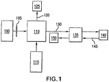
- Figure 1 shows a schematic diagram of -portions of a spectrally and frequency encoded (“SFE") system.
- SFE spectrally and frequency encoded
- light 100 can be filtered by filter 105 to match the absorption band of the fluorophore, and provided into an interferometer 110, which can be a Michelson interferometer, as well as a Sagnac, Mach-Zehnder, Twyman-Green interferometers, etc.
- the input light is affected by the interferometer 110 so as to produce a spectral modulation on the input light.
- Light 130 from the interferometer 110 then can illuminate a dispersive element 135 which can precede or follow a lens.
- Each wavelength component with its unique modulation frequency can be focused at a distinct location on a fluorescent sample 140. Fluorescence in the sample 140 is excited, a fluorescent light 145 returns through the grating lens pair 135, and can be collected and directed to a detector 150.
- the detected light can be processed via a Fourier transformation or the like to recover a fluorescence intensity as a function of one-dimensional location from the sample 140. Additional detectors may be utilized to measure the excitation spectra and/or absorption and/or diffuse reflectance spectra of the sample as a means for correcting for the excitation spectrum shape and/or the absorption and/or scattering artifacts in turbid samples.
- a second reference light 115 is directed to one component of the interferometer and utilized to compensate the nonlinearity of a moving component of the interferometer.
- broadband excitation light which is possibly filtered to match the fluorophore's absorption spectrum
- the number of resolvable points in SFE fluorescence imaging is also governed by Eq. 1.
- the modulated fluorescence light After being dispersed and focused onto the sample the modulated fluorescence light generates fluorescence emission.
- Reconstruction of a single line in the SFE image is performed by taking the Fourier transform of the detected fluorescent signal, following correction by the reference interferometer signal. Multiple SFE lines are acquired as the probe is slowly scanned to create an SFE image.
- FIG. 2 A block diagram of an exemplary embodiment of an interferometer, e.g., the Michelson interferometer, is shown in Figure 2 .
- light 200 is incident on a beam splitter 215, which directs one portion of the light 200 to a stationary mirror 225 and the other portion of the light 200 to a scanning mirror 230.
- the reflected beams return to the beam splitter 215, and are combined to exit the interferometer as spectrally modulated light 235 which is incident upon the sample in the case of the interferometer, or a detector for a reference measurement.
- the beam splitter 215 may be preceded by a filter 205 so as to filter out wavelengths not contained within the fluorophore's excitation spectrum.
- a compensator 220 may be inserted into one arm of the interferometer to correct for a dispersion differences in the mirror arms 225, 230.
- Figure 3 depicts an exemplary embodiment of an apparatus according to the present invention which can be used to indicate the exemplary SFE procedure
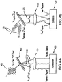
- Figure 4 depicts an exemplary implementation of such procedure in more detail.
- light from a broadband source 302 can be delivered through a filter (F) 308 and single-mode fiber (SMF) 310 to a Michelson interferometer containing a beamsplitter 312 and two mirrors (M), at least one of which may be scanned.
- the interferometer may generate a wavelength dependent frequency modulation on a broadband light 400.
- a pair of a compact grating 316a and a lens 316b as a pair 316 can be used to illuminate a sample 314, 420, thus simulating, e.g., a ⁇ 1 mm diameter miniature endoscope.
- the lens 316b, 415 can focus each of uniquely modulated excitation wavelengths 410 onto a different location of the sample 314 after they had been dispersed by the holographic transmission grating 316a, 405 (being impacted by light 400 having 1200 lines/mm in Figure 4 ), which can be any diffractive element.
- the emitted light was transmitted back through the same lens 316b, 415 and the grating 316a, 405.
- the fluorescence 430 (also shown in Figure 3 as dashed lines), which can be diffracted at a different angle than the reflected light, can then be deflected by a mirror M shown in Figure 3 through an 830 nm long-pass filter LPF, and focused onto a second avalanche photodiode D F by a combination of spherical and cylindrical lenses CL.
- the grating 316a, 405 can be mounted to a galvanometer, and rotated to provide the slow-axis scanning.
- a reconstruction of the exemplary image can be accomplished by taking the Fourier-transform of the modulated fluorescence for each galvanometer scan angle after using the reference signal to correct the interferogram.
- ICG Indocyanine green
- ICG Indocyanine green
- C. H. Tung “Fluorescent peptide probes for in vivo diagnostic imaging,” Biopolymers, Vol. 76(5), 391, (2004 )
- S. Ito et al. "Detection of human gastric cancer in resected specimens using a novel infrared fluorescent anti-human carcinoembryonic antigen antibody with an infrared fluorescence endoscope in vitro," Endoscopy, Vol.
- Figure 5A shows a fluorescence image 500 of microfluidic channels (as described in M. Shin et al., "Endothelialized networks with a vascular geometry in microfabricated poly(dimethyl siloxane),” Biomedical Microdevices, Vol. 6(4), 269 (2004 )) filled with ICG (2 mg ICG/mL DMSO) obtained using the SFE technique.
- a corresponding epi-illuminated reflectance micrograph image 505 is shown in Fig. 5B which demarcates the smallest, 35 ⁇ m wide channels.
- the exemplary SFE image can be collected at 2 Hz with a 1.4 mm x 1.4 mm field of view.
- the center wavelength and spectral range (full-width at 15% maximum) of illumination after low-pass filtering can be 780 nm and 50 nm, respectively.
- the Michelson interferometer scanning mirror can be translated ⁇ 0.25 mm around the zero-path-length difference position to provide a spectral resolution of ⁇ 0.6 nm, corresponding to a theoretical 83 resolvable points. (See J. Kauppinen et al., Fourier Transforms in Spectroscopy, Wiley-VCH, New York, p. 271, (2001 )).
- the probe input beam can be 1.1 mm in diameter, and may be incident on the grating at 22°, also likely resulting in a spectral resolution of 0.6 nm.
- the usable excitation bandwidth of ICG can be 125 nm in DMSO, this probe configuration could theoretically enable >200 resolvable points per frequency-encoded line.
- the limited bandwidth of the current source can reduce this number to, e.g., 84.
- Exemplary lateral resolution measurements along the spectrally encoded line can be estimated by measuring the edge response function of, e.g., 15 lines in the image along the wavelength-encoded axis at vertical edges in the microfluidic channels.
- the exemplary measurements can demonstrate a spatial resolution of 15.9 ⁇ 4.9 ⁇ m (mean ⁇ stdev), corresponding to a total of approximately 88 resolvable points across the field of view. This is in approximate agreement with the expected calculations.
- the resolution along the transverse axis can be limited by the imaging optics.
- This exemplary value can be comparable to state-of-the-art fiber-bundle based technologies of similar diameter, and may be improved by increasing the excitation bandwidth or utilizing a higher density grating while simultaneously increasing the scanning range of the interferometer.
- Exemplary SFE techniques can be advantageous in that high quality imaging may be obtained using a single optical fiber.
- Stokes-shifted fluorescent light may not couple back to the core of a single-mode illumination fiber.
- An exemplary solution to this challenge may be the use of a dual-clad fiber (as described in D. Yelin et al., "Double-clad fiber for endoscopy," Opt. Lett., Vol. 29(20), 2408 (2004 )) such that excitation light can be transmitted through a central core, and the fluorescence may be obtained through the inner cladding.
- this exemplary approach is effective without significantly increasing the probe diameter or compromising resolution.
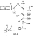
- Figure 6 shows a detailed diagram of an exemplary SFE system utilizing a single dual clad fiber probe in accordance with an exemplary embodiment of the present invention for collecting fluorescent images.
- illumination light generated by a source 600 can be filtered by a filter 605.
- filtered light, and light from a reference 625 can be directed through a Michelson interferometer including a beam splitter 610, a stationary mirror 615, and a moving mirror 620.
- the light provided from the reference 625 can be deflected by a notch filter or a reference beam splitter 622 to a reference detector 630.
- the illumination light can pass through the reference beam splitter 622 and a dichroic filter or beam splitter 635, and can be coupled via a coupler to a central single-mode core of a dual clad fiber 645.
- Light 655 exiting the core of the fiber 645 can be dispersed and focused onto a sample 660 by a dispersive element and lens 650.
- the emitted fluorescence can return through a lens 650 and the dispersive element 650. Since such light is Stokes shifted, it may not easily couple back into the single-mode core, but would likely couple to the inner cladding of the dual-clad fiber 645.
- the emitted fluorescence emerging from the proximal end of the fiber can be deflected by the dichroic filter or beam splitter 635 to a fluorescence detector 640.
- the reflected light can couple directly back into the single-mode core. After passing through the dichroic filter or beam splitter 635, this signal can be directed to an additional detector for a reconstruction of a spectrally encoded reflectance image.
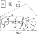
- Figure 7 shows an exemplary embodiment of a distal end of a probe according to the present invention which is configured to utilize the exemplary apparatus shown in Figure 6 and using a dual clad-fiber.
- spectrally modulated light 700 from the interferometer can be provided to a central core 715 of a dual-clad fiber 710 via coupling optics 705.
- Illumination light 720 emerging from the core 715 can be divergent, and collimated by a lens 725, which can be a micro-lens, GRIN lens, etc.
- Collimated light 730 can be dispersed by a dispersive element 735, which may be a transmissive grating, a reflective grating, prism, hologram, or any other diffractive element.
- Dispersed light 745 can be focused onto a sample 750 by a lens 740, thus causing a fluorescence emission.
- the spectrally modulated emitted fluorescence 755 can be gathered by and collimated by the lens 740, transmitted through a grating 735, and focused by the lens 725 to an inner cladding 760 of the dual-clad fiber 710.
- the modulated fluorescence 755 can then be transmitted back down the inner cladding 760 for detection.
- the exemplary SFE arrangements can also be configured to be provided in a multiple fiber configuration.
- a single-mode fiber can be used to send the illumination light to the sample, and one or multiple multi-mode fibers may be used to collect the emitted fluorescence.
- the reflectance image can be reconstructed because the reflected light would couple back to the illumination fiber.
- Figure 8 an exemplary embodiment of a distal end of a probe according to the present invention which is configured to utilize the exemplary apparatus shown in Figure 6 and using two optical fibers.
- the description of this exemplary arrangement is similar to that of Figure 7 provided herein, and elements thereof have the same description, except that elements 700, 705, etc. have been replaced with elements 800, 805, etc., respectively, except as indicated below.
- the spectrally modulated illumination light can be transmitted to the distal end of the probe via single-mode fiber 815.
- the emitted fluorescence can be coupled back to the core of a multimode fiber 860.
- a multimode core 860 of Figure 8 can be replaced by a linear array of multimode fibers 960.
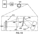
- FIG. 10 Another exemplary embodiment of a distal end of the probe according to the present invention is shown in Figure 10 .
- illumination light 1020 diverging from the illumination fiber can be passed through a lens 1025, which can be a GRIN lens, and/or other types of lenses or objectives.
- the fiber-lens separation can be selected such that the light begins to converge to a focus beyond a grating 1035 and on a sample 1050.
- the emitted fluorescence can then pass through the grating, and may be focused onto collection fiber(s) by the lens 1025.
- the exemplary SFE procedures can also be implemented in configurations that may enable endoscopic fluorescence microscopy.
- a numerical aperture can be greater than 0.3, and may preferably be greater than 0.5. Due to aberrations that may occur when large angles illuminate the grating, as shown in Figure 12 , it may furthermore be advantageous to place a grating 1225 prior to a lens 1230 as is conducted in a technique termed spectrally-encoded confocal microscopy (SECM). (See G. J.
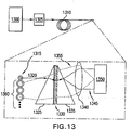
- Figure 13 shows a further exemplary embodiment of the arrangement according to the present invention which can utilize one or more prisms 1325, 1335 in front or behind a grating 1330 in order keep spectrally dispersed light 1345 along the same axis as the optical probe.
- exemplary multiple core/fiber combinations may be utilized to collect the fluorescent light.
- an additional spatial filter comprising one or more fiber apertures 1465 (or a physical aperture such as a slit or pinhole 1460) may be placed at the distal fiber tip of the collection fiber(s) to reject out-of-focus light.
- such exemplary spatial filter 1570 may be placed at the proximal end of the detection fibers in a fiber bundle or array of fibers.
- Single-frequency light 1120 may also pass through the Michelson interferometer 1105.
- a resultant spectrally modulated light 1125 can be detected by a reference correction detector 1130.
- the spectrally modulated light 1125 can have a single modulation frequency with equally spaced zero-crossings. However, non-linearities in the motion of the scanning mirror can change the spacing of the zero-crossings, and may result in an incorrect reconstruction of spectra and image lines when the Fourier transform is performed.
- Exemplary embodiments of a correction procedure according to the present invention as described below can result in a re-interpolation of the data signals, based on the a priori knowledge that the reference signal should have equally-spaced zero-crossings.
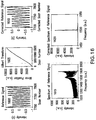
- Figure 16 shows exemplary graphs associated with representative data with respect to this point.
- the original reference signal detected by the reference correction detector 1130 is illustrated in a first graph 1600.
- the correction factor of the upper middle panel can be used to re-interpolate the original data to obtain the trace in a second graph 1610.
- a further graph 1605 illustrates a Hilbert transform of a reference signal used to correct the data.
- the Fourier transform of the uncorrected data is shown in a fourth graph 1615 (e.g., spectrum of monochromatic reference signal prior to correction, obtained as a Fourier transform of the first graph 1600) and a spectrum of monochromatic reference signal after correction, obtained as a Fourier transform of the second graph 1610 is shown in a fourth graph 1620.
- the graphs 1615 and 1620 demonstrate the recovery of a single-frequency signal when the correction factor is applied to the reference data itself. Exemplary applications to other detected signals can be equally effective in a spectral correction procedure.
- each spot on the sample can be illuminated with a different wavelength. For example, by scanning the spectrally encoded line along the sample, approximately parallel to the line of dispersion, each point can be sequentially illuminated by the full bandwidth of the illumination light. By monitoring the intensity at each point as the wavelengths are scanned, the excitation spectrum can be recovered for each location on the sample.
- An exemplary embodiment of the SFE procedure according to the present invention can allow for a recovery of the emission spectrum.
- Each point on the sample can be illuminated by a different wavelength, each of which may be encoded with a different modulation frequency.
- the emission spectrum can be recovered by conventional procedures and/or methods.
- the spectrometer can be dispersive and/or Fourier transform type.
- the Fourier transform-type spectrometer may be a second interferometer added to the exemplary system.
- the illumination light oscillates sinusoidally, forcing the fluorescence emission to oscillate in the same manner.
- the source In order to attain a high number of resolvable points shown in Table 1, it is preferable for the source to be capable of illuminating the entire excitation spectrum. This can be made possible through the use of, e.g., thermal lamps, arc lamps, solid-state lasers, and LEDs. Additionally, alternative sources such as supercontinuum generation with photonic crystal fiber technology can be utilized, the description of which is provided in G. McConnell, "Confocal laser scanning fluorescence microscopy with a visible continuum source," Opt. Express, Vol. 12(13), 2844 (2004 ). The use of broadband NIR lasers as a light source can facilitate SFE two-photon fluorescence imaging.
- the fluorescence imaging can be accomplished with swept-source lasers.
- the frequency encoding is not necessary and the technique reduces to traditional spectral encoding because the individual locations of the sample are sequentially illuminated. It is still possible to obtain excitation, emission, and lifetime spectra with this embodiment, as well as reconstruction of the EEM.
- Eq. 2 is inverse Fourier transformed in step 1710.
- the resultant signal may likely be one line in the image.
- intensity corrections can be accomplished by dividing by the illumination spectrum, as indicated in step 1720.
- An exemplary excitation spectrum can be obtained using the exemplary procedure of Figure 18 , in which, after scanning along the direction of the spectrally encoded line, Eq. 3. is inverse Fourier transformed in step 1810. Then, in step 1820, source cross-correlation spectra is divided (e.g., by an inverse Fourier transform of Eq. 2). An amplitude of resultant signal is an exemplary excitation spectra, and the phase of resultant signal can be related to time constants via Eq. 4, where ⁇ ( ⁇ em , ⁇ ex ) may be the phase difference between the and the source cross-correlation ( ⁇ I ( ⁇ ex ) ).
- the exemplary excitation lifetime can also be obtained.
- the inverse Fourier transform of Eq. 3 for a phase of the resultant signal can be the phase of the fluorescence ( ⁇ ( ⁇ em , ⁇ ex ) ) .
- the inverse Fourier transform of Eq. 1 for the phase of the resultant signal can be the phase of the source cross-correlation ( ⁇ I (k X ) ) .
- Each full scan (e.g., back and forth) of the mirror can correspond to two lines in the image.
- This exemplary correction procedure can utilize a simultaneous acquisition of two interferograms for each line in the image, e.g., (a) the signal of interest, and (b) a signal with a known spectrum, preferably a single-frequency source such as a He-Ne laser, which can be used as a reference to correct the time-traces for non-linear motion of the scanning mirror of the Michelson interferometer.
- step 1910 data is truncated to linear region of scan, containing 2 n data points for efficient Fast Fourier transforms (usually symmetric about the center point, dictated by duty cycle of the driving waveform) in step 1910.
- step 1920 the mean of the data is subtracted from each signal if acquisition was not AC-coupled (e.g., see the first graph 1600 of Figure 16 showing only a small portion of data).
- the signals are then time-reversed for most or all odd scans (e.g., to correct for the opposite direction of the scan) in step 1930.
- step 1940 the Hilbert transform of the reference signal is taken.
- the Fourier transform of a single-frequency laser can be an infinite sine wave with equally spaced zero-crossings.
- the Hilbert transform can be based on the Fast Fourier transform, and the imaginary part may correspond to the original data with a 90° phase shift.
- step 1950 the unwrapped phase of the Hilbert transform of the reference signal is taken (as shown in the graph 1605 of Figure 16 ).
- This can correspond to the actual position of the mirror as a function of time, and may be monotonically increasing (e.g., not locally linear).
- a new linear mirror position can be generated ranging from the minimum to maximum of the actual mirror position - step 1960.
- the signal of interest can be re-interpolated onto the new linear mirror position space, e.g., using the unwrapped phase of the reference Hilbert transform.
- the second graph 1610 of Figure 16 shows the signal of interest which is the reference itself.
- the spectrum of interest can then be determined from the Fourier transform of the interpolated signal in step 1980. For example, see the third and fourth graphs 1615 and 1620 for uncorrected and corrected signals, respectively.
- the time-trace of reference signal can be used to generate a clock signal which may be used to gate the data acquisition at equally spaced mirror locations, thereby automatically correcting the data, and obfuscating the post-processing algorithm described above.
- the broad bandwidth light source can include LED, filament lamp (e.g. Tungsten-halogen, Mercury, Xenon, Deuterium), array of diode lasers, continuum generation source, femtosecond solid-state source, semiconductor optical amplifier, rare-earth doped fiber, ASE source, dye fluorescence, SLED, swept-source laser, etc.
- the reference source can include a monochromatic light source, such as HeNe laser, gas laser, diode laser, filtered broad bandwidth light source, etc.
- the optical fiber can include Dual-clad fiber, single-mode fiber, multimode fiber(s), photonic crystal fiber, hollow-core fiber, hollow waveguide, etc.
- the dispersive element can include transmission grating, reflection grating, hologram, prism, etc.
- the compensator can include a neutral density filter.
- the dispersion compensator can include dual opposing prisms or optical glass, crystal or other dispersion modifier, etc.
- the wavelength dependent frequency can be one or more of the following: Scanning mirror via galvanometer, piezoelectric transducer, or solenoid. Rapidly scanning optical delay line (RSOD) as described in G. J. Tearney et al, "High-speed phase- and group-delay scanning with a grating-based phase control delay line," Optics Letters, Vol.
- RSOD Rapidly scanning optical delay line
- phase control delay line 22(23), 1811 (1997 ), phase control delay line, acousto-optic modulator, electro-optic modulator, spinning helical cam, rotating hologram, spinning mirror array, spinning cube, piezoelectric fiber stretcher, variable reflectance plate beam splitter (Fabry-Perot interferometer), etc.
- the exemplary interferometer can include any arrangement for combining light returned from two arms, such as, e.g., Mach-Zehnder, Sagnac, Michelson, Fabry-Perot interferometers. It is noted that the reflection from these arms is not necessary, and such arrangements can operate in a transmission mode. It is also possible to incorporate polarization beam splitters, common path elements and/or circulators in such exemplary arrangements.
- the dichroic splitter can include an interference filter, diffraction grating, dichroic mirror, etc.
- the exemplary spectral dispersion can be accomplished using Grating spectrometer, Fourier Transform spectrometer, prism spectrometer, etc.
- the exemplary detectors can include photodiode, photomultiplier tube, avalanche photodiode, CCD, etc.
Landscapes
- Health & Medical Sciences (AREA)
- Life Sciences & Earth Sciences (AREA)
- Physics & Mathematics (AREA)
- Pathology (AREA)
- General Health & Medical Sciences (AREA)
- Surgery (AREA)
- Medical Informatics (AREA)
- Biophysics (AREA)
- Veterinary Medicine (AREA)
- Engineering & Computer Science (AREA)
- Biomedical Technology (AREA)
- Heart & Thoracic Surgery (AREA)
- Nuclear Medicine, Radiotherapy & Molecular Imaging (AREA)
- Molecular Biology (AREA)
- Animal Behavior & Ethology (AREA)
- Public Health (AREA)
- Chemical & Material Sciences (AREA)
- Analytical Chemistry (AREA)
- Biochemistry (AREA)
- General Physics & Mathematics (AREA)
- Immunology (AREA)
- Radiology & Medical Imaging (AREA)
- Optics & Photonics (AREA)
- Spectroscopy & Molecular Physics (AREA)
- Investigating, Analyzing Materials By Fluorescence Or Luminescence (AREA)
Claims (24)
- Système d'obtention d'un rayonnement photoluminescent d'au moins une partie d'un échantillon (140), comprenant :un premier agencement (110) configuré pour modifier un premier rayonnement de telle sorte que chacune de ses longueurs d'onde a des caractéristiques différentes des autres, dans lequel les caractéristiques comprennent la modulation de fréquence ou un délai de temporisation ;au moins un second agencement (135) configuré pour :recevoir le premier rayonnement modifié et disperser spatialement et spectralement le premier rayonnement en au moins un deuxième rayonnement et au moins un troisième rayonnement, les deuxième et troisième rayonnements étant fournis à différents emplacements de l'au moins une partie ; etau moins un troisième agencement (150) configuré pour recevoir et détecter le rayonnement photoluminescent de l'au moins une partie sur la base des deuxième et troisième rayonnements, dans lequel l'au moins un deuxième agencement entraîne l'impact d'au moins l'un des deuxième et troisième rayonnements sur différents emplacements, et exciter au moins une partie de l'au moins un échantillon (140) pour générer le rayonnement photoluminescent,dans lequel l'au moins un troisième agencement (150) est en outre configuré pour déterminer un emplacement d'un impact sur l'échantillon par les deuxième et troisième rayonnements sur la base des caractéristiques.
- Système selon la revendication 1, dans lequel l'au moins un deuxième agencement comprend au moins l'un d'un réseau, d'un prisme, d'un grisme, d'un grisme à deux prismes ou d'une lentille.
- Système selon la revendication 1, dans lequel l'au moins un deuxième agencement comprend une lentille ayant une ouverture numérique qui est supérieure à 0,5.
- Système selon la revendication 1, dans lequel au moins un premier agencement comprend au moins une fibre optique.
- Système selon la revendication 4, dans lequel l'au moins une fibre optique a de multiples gaines.
- Système selon la revendication 4, dans lequel l'au moins une fibre optique comprend une pluralité de fibres optiques.
- Système selon la revendication 4, dans lequel l'au moins un agencement comprend au moins un agencement de trou d'épingle ou un agencement de fente.
- Système selon la revendication 4, dans lequel au moins l'une de l'au moins une fibre optique est une fibre multimodale.
- Système selon la revendication 1, comprenant en outre une source de lumière réglable en longueur d'onde configurée pour fournir l'au moins un premier rayonnement.
- Système selon la revendication 1, comprenant en outre une source de lumière configurée pour fournir l'au moins un premier rayonnement qui a de multiples longueurs d'onde.
- Système selon la revendication 1, comprenant en outre un agencement supplémentaire configuré pour moduler les longueurs d'onde d'au moins l'un du deuxième rayonnement ou du troisième rayonnement à différentes fréquences.
- Système selon la revendication 11, dans lequel l'agencement supplémentaire comprend un agencement interférométrique (110).
- Système selon la revendication 12, dans lequel l'agencement interférométrique comprend au moins un composant translatable.
- Système selon la revendication 13, dans lequel l'agencement supplémentaire comprend un agencement interférométrique supplémentaire (318) configuré pour corriger les non-linéarités dans l'au moins un composant translatable.
- Système selon la revendication 11, dans lequel l'agencement supplémentaire comprend au moins un modulateur acousto-optique ou un modulateur électro-optique configuré pour fournir des capacités de codage de fréquence.
- Système selon la revendication 1, dans lequel l'au moins un agencement est configuré pour générer des informations associées aux différents emplacements en fonction du rayonnement photoluminescent, et comprenant en outre un agencement de traitement configuré pour générer au moins une image sur la base des informations.
- Système selon la revendication 16, dans lequel l'agencement de traitement est configuré pour recevoir l'au moins un signal, et pour effectuer une transformée de Fourier sur l'au moins un signal pour générer l'image.
- Système selon la revendication 16, dans lequel l'au moins une image comprend au moins l'une d'une image microscopique ou d'une image endoscopique.
- Système selon la revendication 14, dans lequel l'au moins un agencement comprend un agencement de détection qui est configuré pour recevoir le rayonnement photoluminescent et générer au moins un signal qui est associé au rayonnement photoluminescent.
- Système selon la revendication 1, dans lequel l'au moins un deuxième agencement est configuré pour pouvoir piloter une position des deuxième et troisième rayonnements sur les différents emplacements sur au moins une partie de l'échantillon.
- Procédé d'obtention d'un rayonnement photoluminescent d'au moins une partie d'un échantillon, comprenant :la réception et la modification d'un premier rayonnement de telle sorte que chacune de ses longueurs d'onde a des caractéristiques différentes des autres, dans lequel les caractéristiques comprennent la modulation de fréquence ou un délai de temporisation ;la réception du premier rayonnement modifié et la dispersion spatiale et spectrale du premier rayonnement en au moins un deuxième rayonnement et au moins un troisième rayonnement ;le fait de permettre la fourniture des deuxième et troisième rayonnements à différents emplacements de l'au moins une partie ;l'excitation d'au moins une partie de l'au moins un échantillon (140) pour générer le rayonnement photoluminescent ;la réception et la détection du rayonnement photoluminescent de l'au moins une partie sur la base des deuxième et troisième rayonnements ; etla détermination d'un emplacement d'un impact sur l'échantillon par les deuxième et troisième rayonnements sur la base des caractéristiques.
- Procédé selon la revendication 21, comprenant en outre :la génération d'informations associées aux différents emplacements en fonction du rayonnement photoluminescent ; etla génération d'au moins une image sur la base des informations.
- Procédé selon la revendication 21, dans lequel les différentes caractéristiques comprennent différentes fréquences de modulation du premier rayonnement.
- Système selon la revendication 1, dans lequel les caractéristiques différentes comprennent différentes fréquences de modulation du premier rayonnement.
Applications Claiming Priority (2)
| Application Number | Priority Date | Filing Date | Title |
|---|---|---|---|
| US72721505P | 2005-10-14 | 2005-10-14 | |
| PCT/US2006/040584 WO2007047690A1 (fr) | 2005-10-14 | 2006-10-13 | Imagerie fluorescente codee par frequence et par spectre |
Publications (2)
| Publication Number | Publication Date |
|---|---|
| EP1945094A1 EP1945094A1 (fr) | 2008-07-23 |
| EP1945094B1 true EP1945094B1 (fr) | 2018-09-05 |
Family
ID=37741196
Family Applications (1)
| Application Number | Title | Priority Date | Filing Date |
|---|---|---|---|
| EP06826125.4A Active EP1945094B1 (fr) | 2005-10-14 | 2006-10-13 | Imagerie fluorescente codee par frequence et par spectre |
Country Status (4)
| Country | Link |
|---|---|
| US (1) | US7889348B2 (fr) |
| EP (1) | EP1945094B1 (fr) |
| JP (1) | JP5203951B2 (fr) |
| WO (1) | WO2007047690A1 (fr) |
Cited By (2)
| Publication number | Priority date | Publication date | Assignee | Title |
|---|---|---|---|---|
| EP3413021A4 (fr) * | 2016-02-04 | 2019-09-18 | Jasco Corporation | Procédé de mesure de spectre à l'aide d'un spectromètre de type à transformée de fourier |
| WO2020243475A1 (fr) * | 2019-05-30 | 2020-12-03 | Becton, Dickinson And Company | Correction de phase de signaux multiplexés par radiofréquence |
Families Citing this family (121)
| Publication number | Priority date | Publication date | Assignee | Title |
|---|---|---|---|---|
| US20050107694A1 (en) * | 2003-11-17 | 2005-05-19 | Jansen Floribertus H. | Method and system for ultrasonic tagging of fluorescence |
| US8041409B2 (en) * | 2005-09-08 | 2011-10-18 | Carestream Health, Inc. | Method and apparatus for multi-modal imaging |
| US20100220836A1 (en) | 2005-09-08 | 2010-09-02 | Feke Gilbert D | Apparatus and method for multi-modal imaging |
| US8050735B2 (en) * | 2005-09-08 | 2011-11-01 | Carestream Health, Inc. | Apparatus and method for multi-modal imaging |
| US8660631B2 (en) * | 2005-09-08 | 2014-02-25 | Bruker Biospin Corporation | Torsional support apparatus and method for craniocaudal rotation of animals |
| US8203132B2 (en) * | 2005-09-08 | 2012-06-19 | Carestream Health, Inc. | Apparatus and method for imaging ionizing radiation |
| US20090281383A1 (en) * | 2005-09-08 | 2009-11-12 | Rao Papineni | Apparatus and method for external fluorescence imaging of internal regions of interest in a small animal using an endoscope for internal illumination |
| WO2008060833A2 (fr) | 2006-10-24 | 2008-05-22 | The Research Foundation Of State University Of New York | Composition, procédé, système et trousse pour l'électrophysiologie du nerf optique |
| EP2160217A1 (fr) * | 2007-06-08 | 2010-03-10 | Prescient Medical, Inc. | Configurations de cathéter optique combinant la spectroscopie raman et la réflectométrie de basse cohérence optique à base de fibres |
| US20110160644A1 (en) * | 2007-08-17 | 2011-06-30 | Searete Llc, A Limited Liability Corporation Of The State Of Delaware | Systems, devices, and methods including catheters configured to release ultraviolet energy absorbing agents |
| US8702640B2 (en) * | 2007-08-17 | 2014-04-22 | The Invention Science Fund I, Llc | System, devices, and methods including catheters configured to monitor and inhibit biofilm formation |
| US20090163964A1 (en) * | 2007-08-17 | 2009-06-25 | Searete Llc, A Limited Liability Corporation Of The State Of Delaware | System, devices, and methods including sterilizing excitation delivery implants with general controllers and onboard power |
| US8753304B2 (en) * | 2007-08-17 | 2014-06-17 | The Invention Science Fund I, Llc | Systems, devices, and methods including catheters having acoustically actuatable waveguide components for delivering a sterilizing stimulus to a region proximate a surface of the catheter |
| US20090163977A1 (en) * | 2007-08-17 | 2009-06-25 | Searete Llc, A Limited Liability Corporation Of The State Of Delaware | System, devices, and methods including sterilizing excitation delivery implants with cryptographic logic components |
| US20090048648A1 (en) * | 2007-08-17 | 2009-02-19 | Searete Llc, A Limited Liability Corporation Of The State Of Delaware | Self-sterilizing device |
| US8706211B2 (en) * | 2007-08-17 | 2014-04-22 | The Invention Science Fund I, Llc | Systems, devices, and methods including catheters having self-cleaning surfaces |
| US20090177254A1 (en) * | 2007-08-17 | 2009-07-09 | Searete Llc, A Limited Liability Of The State Of The State Of Delaware | System, devices, and methods including actively-controllable electrostatic and electromagnetic sterilizing excitation delivery system |
| US8734718B2 (en) | 2007-08-17 | 2014-05-27 | The Invention Science Fund I, Llc | Systems, devices, and methods including catheters having an actively controllable therapeutic agent delivery component |
| US8162924B2 (en) * | 2007-08-17 | 2012-04-24 | The Invention Science Fund I, Llc | System, devices, and methods including actively-controllable superoxide water generating systems |
| US8460229B2 (en) * | 2007-08-17 | 2013-06-11 | The Invention Science Fund I, Llc | Systems, devices, and methods including catheters having components that are actively controllable between transmissive and reflective states |
| US8647292B2 (en) * | 2007-08-17 | 2014-02-11 | The Invention Science Fund I, Llc | Systems, devices, and methods including catheters having components that are actively controllable between two or more wettability states |
| US8366652B2 (en) * | 2007-08-17 | 2013-02-05 | The Invention Science Fund I, Llc | Systems, devices, and methods including infection-fighting and monitoring shunts |
| FR2922308B1 (fr) * | 2007-10-11 | 2012-03-16 | Mauna Kea Technologies | Dispositif d'imagerie modulaire, module pour ce dispositif et procede mis en oeuvre par ce dispositif |
| US8218152B1 (en) * | 2007-12-04 | 2012-07-10 | The Board Of Trustees Of The University Of Illinois | Group refractive index reconstruction with broadband interferometric confocal microscopy |
| JP2011508889A (ja) * | 2008-01-04 | 2011-03-17 | コーニンクレッカ フィリップス エレクトロニクス エヌ ヴィ | 光学プローブ |
| TR201901658T4 (tr) | 2008-05-20 | 2019-02-21 | Univ Health Network | Floresan bazli görüntüleme ve i̇zleme i̇çi̇n ci̇haz ve metot |
| US20100092389A1 (en) * | 2008-10-10 | 2010-04-15 | The General Hospital Corporation | Detection of atherosclerosis using indocyanine green |
| US20100113906A1 (en) * | 2008-11-06 | 2010-05-06 | Prescient Medical, Inc. | Hybrid basket catheters |
| US20110208026A1 (en) * | 2008-12-04 | 2011-08-25 | Goodall Eleanor V | Systems, devices, and methods including implantable devices with anti-microbial properties |
| US20110208023A1 (en) * | 2008-12-04 | 2011-08-25 | Goodall Eleanor V | Systems, devices, and methods including implantable devices with anti-microbial properties |
| EP2384168B1 (fr) | 2008-12-04 | 2014-10-08 | Searete LLC | Implants de distribution d'excitation stérilisants à commande active |
| US8585627B2 (en) * | 2008-12-04 | 2013-11-19 | The Invention Science Fund I, Llc | Systems, devices, and methods including catheters configured to monitor biofilm formation having biofilm spectral information configured as a data structure |
| US20110295089A1 (en) | 2008-12-04 | 2011-12-01 | Searete Llc, A Limited Liability Corporation Of The State Of Delaware | Systems, devices, and methods including implantable devices with anti-microbial properties |
| US20110152751A1 (en) * | 2008-12-04 | 2011-06-23 | Searete Llc, A Limited Liability Corporation Of The State Of Delaware | Systems, devices, and methods including catheters having UV-Energy emitting coatings |
| US20110160681A1 (en) * | 2008-12-04 | 2011-06-30 | Searete Llc, A Limited Liability Corporation Of The State Of Delaware | Systems, devices, and methods including catheters having light removable coatings based on a sensed condition |
| KR101061004B1 (ko) * | 2008-12-10 | 2011-09-01 | 한국전기연구원 | 광역학 치료 및 광 검출을 위한 장치 |
| KR20100072612A (ko) * | 2008-12-22 | 2010-07-01 | 한국전자통신연구원 | 측정 시작 시점 결정 장치가 구비된 측정 장치 |
| US20120002210A1 (en) * | 2009-04-28 | 2012-01-05 | Foss Analytical A/S | Optical interferometer |
| US8174761B2 (en) * | 2009-06-10 | 2012-05-08 | Universitat Heidelberg | Total internal reflection interferometer with laterally structured illumination |
| KR101031087B1 (ko) * | 2009-07-23 | 2011-04-25 | 주식회사 와이텔포토닉스 | 파장변환 레이저 시스템 |
| EP2470886A4 (fr) * | 2009-08-26 | 2016-11-02 | Tomophase Inc | Imagerie optique tissulaire basée sur l'imagerie optique dans le domaine des fréquences |
| US20110181885A1 (en) * | 2010-01-22 | 2011-07-28 | Irvine Sensors Corporation | Large Displacement Micro-Lamellar Grating Interferometer |
| EP2506771A4 (fr) * | 2009-12-03 | 2015-01-28 | Searete Llc | Systèmes, dispositifs et procédés comprenant des cathéters, qui sont destinés à empêcher la formation de biofilms |
| JPWO2011074452A1 (ja) * | 2009-12-14 | 2013-04-25 | コニカミノルタホールディングス株式会社 | 干渉計及び該干渉計を用いたフーリエ分光分析器 |
| KR101172745B1 (ko) * | 2010-01-29 | 2012-08-14 | 한국전기연구원 | 생체로부터 발생하는 다중 분광 광 영상 검출 및 광치료를 위한 복합 장치 |
| US8742982B2 (en) * | 2010-03-30 | 2014-06-03 | Sony Corporation | Indirect radar holography apparatus and corresponding method |
| US9046419B2 (en) * | 2010-07-28 | 2015-06-02 | Technion Research & Development Foundation Limited | Systems and methods for spectrally encoded imaging |
| JP5563405B2 (ja) * | 2010-08-24 | 2014-07-30 | 荏原実業株式会社 | 分光画像取得装置及び方法 |
| EP2615966A1 (fr) * | 2010-09-17 | 2013-07-24 | Lltech Management | Système de tomographie par cohérence optique plein champ permettant d'imager un objet |
| PT2634551T (pt) * | 2010-10-28 | 2021-07-15 | Foss Analytical As | Interferómetro e analisador espectroscópico de transformada de fourier |
| JP5633334B2 (ja) | 2010-11-25 | 2014-12-03 | セイコーエプソン株式会社 | 分光測定装置 |
| US9574941B2 (en) | 2011-05-31 | 2017-02-21 | Tornado Spectral Systems, Inc. | Dispersed fourier transform spectrometer, methods and systems |
| US9261405B2 (en) | 2011-07-13 | 2016-02-16 | Konica Minolta, Inc. | Interferometer and spectrometer including same |
| US8642982B2 (en) * | 2012-03-16 | 2014-02-04 | The United States of America, as represented by the Secretary of Commerce, NIST | Fast switching arbitrary frequency light source for broadband spectroscopic applications |
| US9194818B2 (en) * | 2012-04-20 | 2015-11-24 | ASTRODESIGN, Inc. | Distance measurement system and optical resolution improvement apparatus |
| EP2662661A1 (fr) * | 2012-05-07 | 2013-11-13 | Leica Geosystems AG | Appareil de mesure doté d'un interféromètre et d'un milieu d'absorption définissant un spectre de raies épais |
| CN103453395A (zh) * | 2012-05-30 | 2013-12-18 | 财团法人工业技术研究院 | 光源装置 |
| WO2014110290A1 (fr) | 2013-01-09 | 2014-07-17 | The Regents Of The University Of California | Appareil et procédés pour l'imagerie par fluorescence utilisant une excitation multiplexée en radiofréquence |
| US20140285810A1 (en) * | 2013-01-29 | 2014-09-25 | The General Hospital Corporation | Apparatus and method for facilitating mesoscopic spectrally encoded tomography co-registered with optical frequency domain imaging and/or spectrally encoded confocal microscopy |
| US20160178439A1 (en) * | 2013-06-17 | 2016-06-23 | Invenio Imaging Inc. | Methods and systems for coherent raman scattering |
| US9316536B2 (en) | 2013-06-24 | 2016-04-19 | ASTRODESIGN, Inc. | Spatial frequency reproducing apparatus and optical distance measuring apparatus |
| US9217710B2 (en) * | 2013-07-31 | 2015-12-22 | The Arizona Board Of Regents On Behalf Of The University Of Arizona | Method of simultaneous frequency-sweeping lifetime measurements on multiple excitation wavelengths |
| US20150085293A1 (en) * | 2013-09-26 | 2015-03-26 | National Cheng Kung University | Portable system for simultaneously operating optical far field imaging, tomography and spectroscopy |
| US20160228006A1 (en) * | 2013-10-01 | 2016-08-11 | The General Hospital Corporation | System, method and computer-accessible medium for utilizing discrete fourier-transform for frequency near-infrared spectroscopy |
| EP3120130B1 (fr) | 2014-03-18 | 2023-07-26 | The Regents of the University of California | Cytomètre en flux parallèle utilisant un multiplexage à radiofréquence, et procédé |
| WO2015167929A1 (fr) * | 2014-04-28 | 2015-11-05 | Cardiofocus, Inc. | Système et procédé pour visualiser un tissu avec une composition de colorant icg pendant des procédures d'ablation |
| US20150374246A1 (en) | 2014-06-26 | 2015-12-31 | Technion R&D Foundation Ltd. | Blood velocity measurement using correlative spectrally encoded flow cytometry |
| CA2955976A1 (fr) | 2014-07-24 | 2016-01-28 | University Health Network | Collecte et analyse de donnees a des fins de diagnostic |
| US10436716B2 (en) * | 2014-09-24 | 2019-10-08 | Smiths Detection, Inc. | Ubiquitous transmissive raman spectroscopy for stand-off detection |
| US10776654B2 (en) * | 2015-03-10 | 2020-09-15 | Infraredx, Inc. | Assessment of lipid core plaque integrity |
| ES2925353T3 (es) | 2015-10-13 | 2022-10-17 | Omega Biosystems Incorporated | Sistema de citometría de flujo de imágenes de fluorescencia multimodal |
| US9968416B2 (en) * | 2015-12-16 | 2018-05-15 | Novartis Ag | Ophthalmic illumination systems, devices, and methods |
| JPWO2017119389A1 (ja) * | 2016-01-08 | 2018-10-25 | 国立大学法人 東京大学 | フーリエ変換型分光装置 |
| EP3430376A1 (fr) | 2016-03-17 | 2019-01-23 | BD Biosciences | Tri de cellules à l'aide d'un cytomètre de flux à fluorescence à haut débit |
| EP3455608A1 (fr) | 2016-05-12 | 2019-03-20 | BD Biosciences | Cytométrie en flux par imagerie de fluorescence avec résolution d'image améliorée |
| US10969571B2 (en) | 2016-05-30 | 2021-04-06 | Eric Swanson | Few-mode fiber endoscope |
| US10401610B2 (en) | 2016-07-15 | 2019-09-03 | Canon Usa, Inc. | Spectrally encoded probe with multiple diffraction orders |
| WO2018031462A1 (fr) | 2016-08-12 | 2018-02-15 | Canon U.S.A. Inc. | Imagerie à plage de cohérence utilisant une interférence à trajet commun |
| US10006852B2 (en) | 2016-09-13 | 2018-06-26 | Becton, Dickinson And Company | Flow cytometer with optical equalization |
| JP2019534069A (ja) | 2016-09-23 | 2019-11-28 | キヤノン ユーエスエイ, インコーポレイテッドCanon U.S.A., Inc | スペクトル符号化内視鏡検査装置および方法 |
| KR101840132B1 (ko) * | 2016-10-19 | 2018-03-19 | 한국과학기술원 | 다중 산란을 이용한 다기능 광학 장치 및 방법 |
| US10898068B2 (en) | 2016-11-01 | 2021-01-26 | Canon U.S.A., Inc. | Multi-bandwidth spectrally encoded endoscope |
| EP3568058A4 (fr) * | 2017-01-11 | 2020-11-11 | Avedro, Inc. | Systèmes et procédés pour déterminer une distribution de réticulation dans une cornée et/ou des caractéristiques structurales d'une cornée |
| US10682044B2 (en) | 2017-01-12 | 2020-06-16 | Canon U.S.A., Inc. | Spectrally encoded forward view and spectrally encoded multi-view endoscope using back-reflected light between reflective surfaces |
| CN107219638B (zh) * | 2017-05-27 | 2019-05-10 | 辽宁大学 | 基于低通滤波的超分辨率关联成像系统及成像方法 |
| US10895692B2 (en) | 2017-06-01 | 2021-01-19 | Canon U.S.A., Inc. | Fiber optic rotary joints and methods of using and manufacturing same |
| CA3066532A1 (fr) * | 2017-06-06 | 2018-12-13 | University Of Maryland Baltimore County | Systemes et procedes utilisant une spectroscopie raman a impulsion unique a longueurs d'onde multiples |
| US10323926B2 (en) | 2017-06-21 | 2019-06-18 | Canon U.S.A., Inc. | Crosstalk elimination or mitigation in optical coherence tomography |
| DE102017115922C5 (de) * | 2017-07-14 | 2023-03-23 | Precitec Gmbh & Co. Kg | Verfahren und Vorrichtung zur Messung und Einstellung eines Abstands zwischen einem Bearbeitungskopf und einem Werkstück sowie dazugehöriges Verfahren zur Regelung |
| US10825152B2 (en) | 2017-09-14 | 2020-11-03 | Canon U.S.A., Inc. | Distortion measurement and correction for spectrally encoded endoscopy |
| US11147453B2 (en) | 2017-10-03 | 2021-10-19 | Canon U.S.A., Inc. | Calibration for OCT-NIRAF multimodality probe |
| US10357160B2 (en) | 2017-10-05 | 2019-07-23 | Canon U.S.A., Inc. | Image acquiring apparatus, systems, and methods |
| US11224336B2 (en) | 2017-11-17 | 2022-01-18 | Canon U.S.A., Inc. | Rotational extender and/or repeater for rotating fiber based optical imaging systems, and methods and storage mediums for use therewith |
| US10809538B2 (en) | 2017-11-27 | 2020-10-20 | Canon U.S.A., Inc. | Image acquisition apparatus, spectral apparatus, methods, and storage medium for use with same |
| US10758415B2 (en) | 2018-01-17 | 2020-09-01 | Topcon Medical Systems, Inc. | Method and apparatus for using multi-clad fiber for spot size selection |
| US10952616B2 (en) | 2018-03-30 | 2021-03-23 | Canon U.S.A., Inc. | Fluorescence imaging apparatus |
| US10506922B2 (en) | 2018-04-06 | 2019-12-17 | Canon U.S.A., Inc. | Spectrometer for color spectrally-encoded endoscopy |
| JP7075371B2 (ja) | 2018-05-03 | 2022-05-25 | キヤノン ユーエスエイ,インコーポレイテッド | マルチプルイメージングモダリティにわたって関心領域を強調するためのデバイス、システム、および方法 |
| US11382516B2 (en) | 2018-06-08 | 2022-07-12 | Canon U.S.A., Inc. | Apparatuses, methods, and storage mediums for lumen and artifacts detection in one or more images, such as in optical coherence tomography images |
| CN108627099B (zh) * | 2018-07-02 | 2020-03-20 | 清华大学 | 五自由度外差光栅干涉测量系统 |
| WO2020009150A1 (fr) * | 2018-07-06 | 2020-01-09 | 国立大学法人東京大学 | Appareil de spectroscopie à transformée de fourier à balayage grande vitesse et procédé de spectroscopie |
| WO2020028367A1 (fr) * | 2018-07-31 | 2020-02-06 | The Penn State Research Foundation | Imagerie à codage spectral utilisant des sondes d'imagerie à décalage de bande |
| US10743749B2 (en) | 2018-09-14 | 2020-08-18 | Canon U.S.A., Inc. | System and method for detecting optical probe connection |
| WO2020205043A1 (fr) * | 2019-03-31 | 2020-10-08 | Agilent Technologies, Inc. | Système de balayage à infrarouge moyen pour analyser des particules microscopiques |
| US11175126B2 (en) | 2019-04-08 | 2021-11-16 | Canon U.S.A., Inc. | Automated polarization control |
| US11707186B2 (en) | 2019-06-14 | 2023-07-25 | Canon U.S.A., Inc. | Fluorescence or auto-fluorescence trigger or triggers |
| US11704918B2 (en) | 2019-07-10 | 2023-07-18 | Becton, Dickinson And Company | Reconfigurable integrated circuits for adjusting cell sorting classification |
| US20210077037A1 (en) | 2019-09-17 | 2021-03-18 | Canon U.S.A., Inc. | Constructing or reconstructing 3d structure(s) |
| US20220346885A1 (en) | 2019-09-20 | 2022-11-03 | Canon U.S.A., Inc. | Artificial intelligence coregistration and marker detection, including machine learning and using results thereof |
| US11963740B2 (en) | 2019-12-05 | 2024-04-23 | Canon U.S.A., Inc. | Lumen, stent, and/or artifact detection in one or more images, such as in optical coherence tomography images |
| JP2023510438A (ja) * | 2019-12-31 | 2023-03-14 | イルミナ インコーポレイテッド | 光学試料分析におけるオートフォーカス機能 |
| AU2021275676A1 (en) | 2020-05-19 | 2022-12-08 | Becton, Dickinson And Company | Methods for modulating an intensity profile of a laser beam and systems for same |
| EP3916365A1 (fr) * | 2020-05-25 | 2021-12-01 | Aragon Photonics Labs, S.L.U. | Procédé et système d'interrogation de fibres optiques |
| CN116171383A (zh) | 2020-06-26 | 2023-05-26 | 贝克顿·迪金森公司 | 用于照射流体流中的样品的双激励光束及其使用方法 |
| US11922633B2 (en) | 2020-06-30 | 2024-03-05 | Canon U.S.A., Inc. | Real-time lumen distance calculation based on three-dimensional (3D) A-line signal data |
| US11944778B2 (en) | 2020-08-06 | 2024-04-02 | Canon U.S.A., Inc. | Methods and systems for automatic pullback trigger |
| US11920929B2 (en) | 2020-08-06 | 2024-03-05 | Canon U.S.A., Inc. | Detecting and guiding optical connection(s) for one or more imaging modalities, such as in optical coherence tomography |
| US11972561B2 (en) | 2020-08-06 | 2024-04-30 | Canon U.S.A., Inc. | Auto-pullback triggering method for intracoronary imaging apparatuses or systems using blood clearing |
| US20220044428A1 (en) | 2020-08-06 | 2022-02-10 | Canon U.S.A., Inc. | Methods and systems for image synchronization |
| US20220110527A1 (en) * | 2020-10-09 | 2022-04-14 | QuantuMed Pty Ltd | Cellular ionic activity visualisation |
| CN114024810B (zh) * | 2021-11-03 | 2023-05-23 | 南京信息工程大学 | 一种多芯光纤信道调制格式识别方法及其装置 |
Family Cites Families (424)
| Publication number | Priority date | Publication date | Assignee | Title |
|---|---|---|---|---|
| US2339754A (en) * | 1941-03-04 | 1944-01-25 | Westinghouse Electric & Mfg Co | Supervisory apparatus |
| US3090753A (en) | 1960-08-02 | 1963-05-21 | Exxon Research Engineering Co | Ester oil compositions containing acid anhydride |
| GB1257778A (fr) | 1967-12-07 | 1971-12-22 | ||
| US3601480A (en) | 1968-07-10 | 1971-08-24 | Physics Int Co | Optical tunnel high-speed camera system |
| US3872407A (en) | 1972-09-01 | 1975-03-18 | Us Navy | Rapidly tunable laser |
| JPS584481Y2 (ja) | 1973-06-23 | 1983-01-26 | オリンパス光学工業株式会社 | ナイシキヨウシヤヘンカンコウガクケイ |
| FR2253410A5 (fr) | 1973-12-03 | 1975-06-27 | Inst Nat Sante Rech Med | |
| US3983507A (en) | 1975-01-06 | 1976-09-28 | Research Corporation | Tunable laser systems and method |
| US3973219A (en) | 1975-04-24 | 1976-08-03 | Cornell Research Foundation, Inc. | Very rapidly tuned cw dye laser |
| US4030831A (en) | 1976-03-22 | 1977-06-21 | The United States Of America As Represented By The Secretary Of The Navy | Phase detector for optical figure sensing |
| US4224929A (en) | 1977-11-08 | 1980-09-30 | Olympus Optical Co., Ltd. | Endoscope with expansible cuff member and operation section |
| FR2448728A1 (fr) | 1979-02-07 | 1980-09-05 | Thomson Csf | Dispositif joint tournant pour liaison par conducteurs optiques et systeme comportant un tel dispositif |
| US4300816A (en) | 1979-08-30 | 1981-11-17 | United Technologies Corporation | Wide band multicore optical fiber |
| US4295738A (en) | 1979-08-30 | 1981-10-20 | United Technologies Corporation | Fiber optic strain sensor |
| US4428643A (en) | 1981-04-08 | 1984-01-31 | Xerox Corporation | Optical scanning system with wavelength shift correction |
| US5065331A (en) | 1981-05-18 | 1991-11-12 | Vachon Reginald I | Apparatus and method for determining the stress and strain in pipes, pressure vessels, structural members and other deformable bodies |
| GB2106736B (en) | 1981-09-03 | 1985-06-12 | Standard Telephones Cables Ltd | Optical transmission system |
| US4479499A (en) | 1982-01-29 | 1984-10-30 | Alfano Robert R | Method and apparatus for detecting the presence of caries in teeth using visible light |
| US4601036A (en) | 1982-09-30 | 1986-07-15 | Honeywell Inc. | Rapidly tunable laser |
| HU187188B (en) | 1982-11-25 | 1985-11-28 | Koezponti Elelmiszeripari | Device for generating radiation of controllable spectral structure |
| CH663466A5 (fr) * | 1983-09-12 | 1987-12-15 | Battelle Memorial Institute | Procede et dispositif pour determiner la position d'un objet par rapport a une reference. |
| US4639999A (en) * | 1984-11-02 | 1987-02-03 | Xerox Corporation | High resolution, high efficiency I.R. LED printing array fabrication method |
| US4763977A (en) | 1985-01-09 | 1988-08-16 | Canadian Patents And Development Limited-Societe | Optical fiber coupler with tunable coupling ratio and method of making |
| US5318024A (en) | 1985-03-22 | 1994-06-07 | Massachusetts Institute Of Technology | Laser endoscope for spectroscopic imaging |
| EP0590268B1 (fr) | 1985-03-22 | 1998-07-01 | Massachusetts Institute Of Technology | Sonde comprenant des fibres optiques destiné à l'analyse spectrale de tissus |
| US4631498A (en) | 1985-04-26 | 1986-12-23 | Hewlett-Packard Company | CW Laser wavemeter/frequency locking technique |
| US4650327A (en) | 1985-10-28 | 1987-03-17 | Oximetrix, Inc. | Optical catheter calibrating assembly |
| US5040889A (en) | 1986-05-30 | 1991-08-20 | Pacific Scientific Company | Spectrometer with combined visible and ultraviolet sample illumination |
| CA1290019C (fr) | 1986-06-20 | 1991-10-01 | Hideo Kuwahara | Recepteur de signaux lumineux a dedoublement |
| US4770492A (en) | 1986-10-28 | 1988-09-13 | Spectran Corporation | Pressure or strain sensitive optical fiber |
| JPH0824665B2 (ja) | 1986-11-28 | 1996-03-13 | オリンパス光学工業株式会社 | 内視鏡装置 |
| US4744656A (en) | 1986-12-08 | 1988-05-17 | Spectramed, Inc. | Disposable calibration boot for optical-type cardiovascular catheter |
| US4751706A (en) | 1986-12-31 | 1988-06-14 | The United States Of America As Represented By The Secretary Of The Army | Laser for providing rapid sequence of different wavelengths |
| US4834111A (en) | 1987-01-12 | 1989-05-30 | The Trustees Of Columbia University In The City Of New York | Heterodyne interferometer |
| GB2209221B (en) | 1987-09-01 | 1991-10-23 | Litton Systems Inc | Hydrophone demodulator circuit and method |
| US5202931A (en) * | 1987-10-06 | 1993-04-13 | Cell Analysis Systems, Inc. | Methods and apparatus for the quantitation of nuclear protein |
| US4909631A (en) | 1987-12-18 | 1990-03-20 | Tan Raul Y | Method for film thickness and refractive index determination |
| US4890901A (en) | 1987-12-22 | 1990-01-02 | Hughes Aircraft Company | Color corrector for embedded prisms |
| US4892406A (en) | 1988-01-11 | 1990-01-09 | United Technologies Corporation | Method of and arrangement for measuring vibrations |
| FR2626367B1 (fr) * | 1988-01-25 | 1990-05-11 | Thomson Csf | Capteur de temperature multipoints a fibre optique |
| FR2626383B1 (fr) | 1988-01-27 | 1991-10-25 | Commissariat Energie Atomique | Procede de microscopie optique confocale a balayage et en profondeur de champ etendue et dispositifs pour la mise en oeuvre du procede |
| US4925302A (en) * | 1988-04-13 | 1990-05-15 | Hewlett-Packard Company | Frequency locking device |
| US4998972A (en) | 1988-04-28 | 1991-03-12 | Thomas J. Fogarty | Real time angioscopy imaging system |
| US5730731A (en) | 1988-04-28 | 1998-03-24 | Thomas J. Fogarty | Pressure-based irrigation accumulator |
| US4905169A (en) | 1988-06-02 | 1990-02-27 | The United States Of America As Represented By The United States Department Of Energy | Method and apparatus for simultaneously measuring a plurality of spectral wavelengths present in electromagnetic radiation |
| US5242437A (en) | 1988-06-10 | 1993-09-07 | Trimedyne Laser Systems, Inc. | Medical device applying localized high intensity light and heat, particularly for destruction of the endometrium |
| DE02012428T1 (de) | 1988-07-13 | 2005-12-15 | Optiscan Pty. Ltd., Toorak | Konfokales Rastermikroskop |
| GB8817672D0 (en) | 1988-07-25 | 1988-09-01 | Sira Ltd | Optical apparatus |
| US5214538A (en) | 1988-07-25 | 1993-05-25 | Keymed (Medical And Industrial Equipment) Limited | Optical apparatus |
| US4868834A (en) | 1988-09-14 | 1989-09-19 | The United States Of America As Represented By The Secretary Of The Army | System for rapidly tuning a low pressure pulsed laser |
| DE3833602A1 (de) * | 1988-10-03 | 1990-02-15 | Krupp Gmbh | Spektrometer zur gleichzeitigen intensitaetsmessung in verschiedenen spektralbereichen |
| US4940328A (en) | 1988-11-04 | 1990-07-10 | Georgia Tech Research Corporation | Optical sensing apparatus and method |
| US5419323A (en) * | 1988-12-21 | 1995-05-30 | Massachusetts Institute Of Technology | Method for laser induced fluorescence of tissue |
| US5046501A (en) | 1989-01-18 | 1991-09-10 | Wayne State University | Atherosclerotic identification |
| US5085496A (en) | 1989-03-31 | 1992-02-04 | Sharp Kabushiki Kaisha | Optical element and optical pickup device comprising it |
| US5317389A (en) * | 1989-06-12 | 1994-05-31 | California Institute Of Technology | Method and apparatus for white-light dispersed-fringe interferometric measurement of corneal topography |
| US4965599A (en) | 1989-11-13 | 1990-10-23 | Eastman Kodak Company | Scanning apparatus for halftone image screen writing |
| US4984888A (en) * | 1989-12-13 | 1991-01-15 | Imo Industries, Inc. | Two-dimensional spectrometer |
| KR930003307B1 (ko) | 1989-12-14 | 1993-04-24 | 주식회사 금성사 | 입체용 프로젝터 |
| US5251009A (en) | 1990-01-22 | 1993-10-05 | Ciba-Geigy Corporation | Interferometric measuring arrangement for refractive index measurements in capillary tubes |
| DD293205B5 (de) | 1990-03-05 | 1995-06-29 | Zeiss Carl Jena Gmbh | Lichtleiterfuehrung fuer ein medizinisches Beobachtungsgeraet |
| US5039193A (en) | 1990-04-03 | 1991-08-13 | Focal Technologies Incorporated | Fibre optic single mode rotary joint |
| US5262644A (en) | 1990-06-29 | 1993-11-16 | Southwest Research Institute | Remote spectroscopy for raman and brillouin scattering |
| US5197470A (en) * | 1990-07-16 | 1993-03-30 | Eastman Kodak Company | Near infrared diagnostic method and instrument |
| GB9015793D0 (en) * | 1990-07-18 | 1990-09-05 | Medical Res Council | Confocal scanning optical microscope |
| US5127730A (en) | 1990-08-10 | 1992-07-07 | Regents Of The University Of Minnesota | Multi-color laser scanning confocal imaging system |
| US5845639A (en) | 1990-08-10 | 1998-12-08 | Board Of Regents Of The University Of Washington | Optical imaging methods |
| US5305759A (en) * | 1990-09-26 | 1994-04-26 | Olympus Optical Co., Ltd. | Examined body interior information observing apparatus by using photo-pulses controlling gains for depths |
| US5241364A (en) | 1990-10-19 | 1993-08-31 | Fuji Photo Film Co., Ltd. | Confocal scanning type of phase contrast microscope and scanning microscope |
| US5250186A (en) | 1990-10-23 | 1993-10-05 | Cetus Corporation | HPLC light scattering detector for biopolymers |
| US5202745A (en) * | 1990-11-07 | 1993-04-13 | Hewlett-Packard Company | Polarization independent optical coherence-domain reflectometry |
| US5275594A (en) | 1990-11-09 | 1994-01-04 | C. R. Bard, Inc. | Angioplasty system having means for identification of atherosclerotic plaque |
| JP3035336B2 (ja) * | 1990-11-27 | 2000-04-24 | 興和株式会社 | 血流測定装置 |
| US5228001A (en) | 1991-01-23 | 1993-07-13 | Syracuse University | Optical random access memory |
| US5784162A (en) | 1993-08-18 | 1998-07-21 | Applied Spectral Imaging Ltd. | Spectral bio-imaging methods for biological research, medical diagnostics and therapy |
| US6198532B1 (en) * | 1991-02-22 | 2001-03-06 | Applied Spectral Imaging Ltd. | Spectral bio-imaging of the eye |
| US5293872A (en) * | 1991-04-03 | 1994-03-15 | Alfano Robert R | Method for distinguishing between calcified atherosclerotic tissue and fibrous atherosclerotic tissue or normal cardiovascular tissue using Raman spectroscopy |
| US6564087B1 (en) * | 1991-04-29 | 2003-05-13 | Massachusetts Institute Of Technology | Fiber optic needle probes for optical coherence tomography imaging |
| US5465147A (en) | 1991-04-29 | 1995-11-07 | Massachusetts Institute Of Technology | Method and apparatus for acquiring images using a ccd detector array and no transverse scanner |
| WO1992019930A1 (fr) | 1991-04-29 | 1992-11-12 | Massachusetts Institute Of Technology | Procede et appareil d'imagerie optique et de mesure |
| US6501551B1 (en) | 1991-04-29 | 2002-12-31 | Massachusetts Institute Of Technology | Fiber optic imaging endoscope interferometer with at least one faraday rotator |
| US5748598A (en) * | 1995-12-22 | 1998-05-05 | Massachusetts Institute Of Technology | Apparatus and methods for reading multilayer storage media using short coherence length sources |
| US6134003A (en) | 1991-04-29 | 2000-10-17 | Massachusetts Institute Of Technology | Method and apparatus for performing optical measurements using a fiber optic imaging guidewire, catheter or endoscope |
| US6111645A (en) | 1991-04-29 | 2000-08-29 | Massachusetts Institute Of Technology | Grating based phase control optical delay line |
| US5956355A (en) | 1991-04-29 | 1999-09-21 | Massachusetts Institute Of Technology | Method and apparatus for performing optical measurements using a rapidly frequency-tuned laser |
| US6485413B1 (en) | 1991-04-29 | 2002-11-26 | The General Hospital Corporation | Methods and apparatus for forward-directed optical scanning instruments |
| US5441053A (en) | 1991-05-03 | 1995-08-15 | University Of Kentucky Research Foundation | Apparatus and method for multiple wavelength of tissue |
| US5281811A (en) * | 1991-06-17 | 1994-01-25 | Litton Systems, Inc. | Digital wavelength division multiplex optical transducer having an improved decoder |
| US5208651A (en) * | 1991-07-16 | 1993-05-04 | The Regents Of The University Of California | Apparatus and method for measuring fluorescence intensities at a plurality of wavelengths and lifetimes |
| DE4128744C1 (fr) * | 1991-08-29 | 1993-04-22 | Siemens Ag, 8000 Muenchen, De | |
| US5353790A (en) | 1992-01-17 | 1994-10-11 | Board Of Regents, The University Of Texas System | Method and apparatus for optical measurement of bilirubin in tissue |
| US5212667A (en) | 1992-02-03 | 1993-05-18 | General Electric Company | Light imaging in a scattering medium, using ultrasonic probing and speckle image differencing |
| US5248876A (en) | 1992-04-21 | 1993-09-28 | International Business Machines Corporation | Tandem linear scanning confocal imaging system with focal volumes at different heights |
| US5486701A (en) * | 1992-06-16 | 1996-01-23 | Prometrix Corporation | Method and apparatus for measuring reflectance in two wavelength bands to enable determination of thin film thickness |
| US5716324A (en) | 1992-08-25 | 1998-02-10 | Fuji Photo Film Co., Ltd. | Endoscope with surface and deep portion imaging systems |
| US5348003A (en) | 1992-09-03 | 1994-09-20 | Sirraya, Inc. | Method and apparatus for chemical analysis |
| US5698397A (en) | 1995-06-07 | 1997-12-16 | Sri International | Up-converting reporters for biological and other assays using laser excitation techniques |
| US5772597A (en) | 1992-09-14 | 1998-06-30 | Sextant Medical Corporation | Surgical tool end effector |
| US5383467A (en) * | 1992-11-18 | 1995-01-24 | Spectrascience, Inc. | Guidewire catheter and apparatus for diagnostic imaging |
| DE69309953T2 (de) | 1992-11-18 | 1997-09-25 | Spectrascience Inc | Diagnosebildgerät |
| JPH06222242A (ja) * | 1993-01-27 | 1994-08-12 | Shin Etsu Chem Co Ltd | 光ファイバカプラおよびその製造方法 |
| US5987346A (en) | 1993-02-26 | 1999-11-16 | Benaron; David A. | Device and method for classification of tissue |
| JP3112595B2 (ja) * | 1993-03-17 | 2000-11-27 | 安藤電気株式会社 | 光周波数シフタを用いる光ファイバ歪位置測定装置 |
| FI93781C (fi) | 1993-03-18 | 1995-05-26 | Wallac Oy | Biospesifinen multiparametrinen määritysmenetelmä |
| DE4309056B4 (de) | 1993-03-20 | 2006-05-24 | Häusler, Gerd, Prof. Dr. | Verfahren und Vorrichtung zur Ermittlung der Entfernung und Streuintensität von streuenden Punkten |
| US5485079A (en) | 1993-03-29 | 1996-01-16 | Matsushita Electric Industrial Co., Ltd. | Magneto-optical element and optical magnetic field sensor |
| DE4310209C2 (de) * | 1993-03-29 | 1996-05-30 | Bruker Medizintech | Optische stationäre Bildgebung in stark streuenden Medien |
| US5424827A (en) | 1993-04-30 | 1995-06-13 | Litton Systems, Inc. | Optical system and method for eliminating overlap of diffraction spectra |
| SE501932C2 (sv) * | 1993-04-30 | 1995-06-26 | Ericsson Telefon Ab L M | Anordning och förfarande för dispersionskompensering i ett fiberoptiskt transmissionssystem |
| DE4314189C1 (de) * | 1993-04-30 | 1994-11-03 | Bodenseewerk Geraetetech | Vorrichtung zur Untersuchung von Lichtleitfasern aus Glas mittels Heterodyn-Brillouin-Spektroskopie |
| US5454807A (en) | 1993-05-14 | 1995-10-03 | Boston Scientific Corporation | Medical treatment of deeply seated tissue using optical radiation |
| JP3292935B2 (ja) * | 1993-05-18 | 2002-06-17 | 富士写真フイルム株式会社 | 蛍光分光画像計測装置 |
| DE69418248T2 (de) | 1993-06-03 | 1999-10-14 | Hamamatsu Photonics Kk | Optisches Laser-Abtastsystem mit Axikon |
| JP3234353B2 (ja) | 1993-06-15 | 2001-12-04 | 富士写真フイルム株式会社 | 断層情報読取装置 |
| US5803082A (en) | 1993-11-09 | 1998-09-08 | Staplevision Inc. | Omnispectramammography |
| US5983125A (en) | 1993-12-13 | 1999-11-09 | The Research Foundation Of City College Of New York | Method and apparatus for in vivo examination of subcutaneous tissues inside an organ of a body using optical spectroscopy |
| US5450203A (en) | 1993-12-22 | 1995-09-12 | Electroglas, Inc. | Method and apparatus for determining an objects position, topography and for imaging |
| US5411016A (en) | 1994-02-22 | 1995-05-02 | Scimed Life Systems, Inc. | Intravascular balloon catheter for use in combination with an angioscope |
| US5590660A (en) * | 1994-03-28 | 1997-01-07 | Xillix Technologies Corp. | Apparatus and method for imaging diseased tissue using integrated autofluorescence |
| DE4411017C2 (de) | 1994-03-30 | 1995-06-08 | Alexander Dr Knuettel | Optische stationäre spektroskopische Bildgebung in stark streuenden Objekten durch spezielle Lichtfokussierung und Signal-Detektion von Licht unterschiedlicher Wellenlängen |
| TW275570B (fr) * | 1994-05-05 | 1996-05-11 | Boehringer Mannheim Gmbh | |
| US5459325A (en) | 1994-07-19 | 1995-10-17 | Molecular Dynamics, Inc. | High-speed fluorescence scanner |
| US6159445A (en) | 1994-07-20 | 2000-12-12 | Nycomed Imaging As | Light imaging contrast agents |
| EP1231496B1 (fr) | 1994-08-18 | 2004-12-29 | Carl Zeiss AG | Appareil chirurgical assisté par tomographie avec cohérence optique |
| US5491524A (en) | 1994-10-05 | 1996-02-13 | Carl Zeiss, Inc. | Optical coherence tomography corneal mapping apparatus |
| US5740808A (en) | 1996-10-28 | 1998-04-21 | Ep Technologies, Inc | Systems and methods for guilding diagnostic or therapeutic devices in interior tissue regions |
| US5817144A (en) | 1994-10-25 | 1998-10-06 | Latis, Inc. | Method for contemporaneous application OF laser energy and localized pharmacologic therapy |
| US6033721A (en) * | 1994-10-26 | 2000-03-07 | Revise, Inc. | Image-based three-axis positioner for laser direct write microchemical reaction |
| US5566267A (en) | 1994-12-15 | 1996-10-15 | Ceram Optec Industries Inc. | Flat surfaced optical fibers and diode laser medical delivery devices |
| US5600486A (en) * | 1995-01-30 | 1997-02-04 | Lockheed Missiles And Space Company, Inc. | Color separation microlens |
| US5648848A (en) | 1995-02-01 | 1997-07-15 | Nikon Precision, Inc. | Beam delivery apparatus and method for interferometry using rotatable polarization chucks |
| DE19506484C2 (de) | 1995-02-24 | 1999-09-16 | Stiftung Fuer Lasertechnologie | Verfahren und Vorrichtung zur selektiven nichtinvasiven Lasermyographie (LMG) |
| RU2100787C1 (ru) * | 1995-03-01 | 1997-12-27 | Геликонов Валентин Михайлович | Оптоволоконный интерферометр и оптоволоконный пьезоэлектрический преобразователь |
| US5526338A (en) | 1995-03-10 | 1996-06-11 | Yeda Research & Development Co. Ltd. | Method and apparatus for storage and retrieval with multilayer optical disks |
| US5697373A (en) | 1995-03-14 | 1997-12-16 | Board Of Regents, The University Of Texas System | Optical method and apparatus for the diagnosis of cervical precancers using raman and fluorescence spectroscopies |
| US5735276A (en) * | 1995-03-21 | 1998-04-07 | Lemelson; Jerome | Method and apparatus for scanning and evaluating matter |
| CA2215975A1 (fr) | 1995-03-24 | 1996-10-03 | Optiscan Pty. Ltd. | Imageur confocal a fibre optique a commande quasi confocale variable |
| US5565983A (en) | 1995-05-26 | 1996-10-15 | The Perkin-Elmer Corporation | Optical spectrometer for detecting spectra in separate ranges |
| US5785651A (en) | 1995-06-07 | 1998-07-28 | Keravision, Inc. | Distance measuring confocal microscope |
| WO1997001167A1 (fr) | 1995-06-21 | 1997-01-09 | Massachusetts Institute Of Technology | Appareil et procede permettant d'acceder a des donnees enregistrees sur des supports optiques multichouches |
| ATA107495A (de) | 1995-06-23 | 1996-06-15 | Fercher Adolf Friedrich Dr | Kohärenz-biometrie und -tomographie mit dynamischem kohärentem fokus |
| CN1200174A (zh) * | 1995-08-24 | 1998-11-25 | 普渡研究基金会 | 基于荧光寿命的人体组织及其它无规则介质成象技术和光谱技术 |
| US6016197A (en) | 1995-08-25 | 2000-01-18 | Ceramoptec Industries Inc. | Compact, all-optical spectrum analyzer for chemical and biological fiber optic sensors |
| FR2738343B1 (fr) | 1995-08-30 | 1997-10-24 | Cohen Sabban Joseph | Dispositif de microstratigraphie optique |
| US6763261B2 (en) | 1995-09-20 | 2004-07-13 | Board Of Regents, The University Of Texas System | Method and apparatus for detecting vulnerable atherosclerotic plaque |
| US6615071B1 (en) | 1995-09-20 | 2003-09-02 | Board Of Regents, The University Of Texas System | Method and apparatus for detecting vulnerable atherosclerotic plaque |
| DE69622764T2 (de) | 1995-09-20 | 2003-04-24 | Texas Heart Inst Houston | yNZEIGE VON THERMISCHEN UNSTETIGKEITEN AN GEFÄSSWÄNDEN |
| DE19542955C2 (de) | 1995-11-17 | 1999-02-18 | Schwind Gmbh & Co Kg Herbert | Endoskop |
| US5719399A (en) * | 1995-12-18 | 1998-02-17 | The Research Foundation Of City College Of New York | Imaging and characterization of tissue based upon the preservation of polarized light transmitted therethrough |
| US5748318A (en) | 1996-01-23 | 1998-05-05 | Brown University Research Foundation | Optical stress generator and detector |
| US5840023A (en) | 1996-01-31 | 1998-11-24 | Oraevsky; Alexander A. | Optoacoustic imaging for medical diagnosis |
| US5642194A (en) | 1996-02-05 | 1997-06-24 | The Regents Of The University Of California | White light velocity interferometer |
| US5862273A (en) | 1996-02-23 | 1999-01-19 | Kaiser Optical Systems, Inc. | Fiber optic probe with integral optical filtering |
| US5843000A (en) | 1996-05-07 | 1998-12-01 | The General Hospital Corporation | Optical biopsy forceps and method of diagnosing tissue |
| ATA84696A (de) * | 1996-05-14 | 1998-03-15 | Adolf Friedrich Dr Fercher | Verfahren und anordnungen zur kontrastanhebung in der optischen kohärenztomographie |
| US6020963A (en) | 1996-06-04 | 2000-02-01 | Northeastern University | Optical quadrature Interferometer |
| US5795295A (en) | 1996-06-25 | 1998-08-18 | Carl Zeiss, Inc. | OCT-assisted surgical microscope with multi-coordinate manipulator |
| US5842995A (en) | 1996-06-28 | 1998-12-01 | Board Of Regents, The Univerisity Of Texas System | Spectroscopic probe for in vivo measurement of raman signals |
| US6245026B1 (en) | 1996-07-29 | 2001-06-12 | Farallon Medsystems, Inc. | Thermography catheter |
| US6396941B1 (en) | 1996-08-23 | 2002-05-28 | Bacus Research Laboratories, Inc. | Method and apparatus for internet, intranet, and local viewing of virtual microscope slides |
| US5840075A (en) | 1996-08-23 | 1998-11-24 | Eclipse Surgical Technologies, Inc. | Dual laser device for transmyocardial revascularization procedures |
| JPH1090603A (ja) | 1996-09-18 | 1998-04-10 | Olympus Optical Co Ltd | 内視鏡光学系 |
| US5801831A (en) | 1996-09-20 | 1998-09-01 | Institute For Space And Terrestrial Science | Fabry-Perot spectrometer for detecting a spatially varying spectral signature of an extended source |
| US6249349B1 (en) | 1996-09-27 | 2001-06-19 | Vincent Lauer | Microscope generating a three-dimensional representation of an object |
| DE19640495C2 (de) | 1996-10-01 | 1999-12-16 | Leica Microsystems | Vorrichtung zur konfokalen Oberflächenvermessung |
| US5843052A (en) | 1996-10-04 | 1998-12-01 | Benja-Athon; Anuthep | Irrigation kit for application of fluids and chemicals for cleansing and sterilizing wounds |
| US6044288A (en) * | 1996-11-08 | 2000-03-28 | Imaging Diagnostics Systems, Inc. | Apparatus and method for determining the perimeter of the surface of an object being scanned |
| US5872879A (en) | 1996-11-25 | 1999-02-16 | Boston Scientific Corporation | Rotatable connecting optical fibers |
| US6517532B1 (en) | 1997-05-15 | 2003-02-11 | Palomar Medical Technologies, Inc. | Light energy delivery head |
| US6437867B2 (en) | 1996-12-04 | 2002-08-20 | The Research Foundation Of The City University Of New York | Performing selected optical measurements with optical coherence domain reflectometry |
| US6249630B1 (en) | 1996-12-13 | 2001-06-19 | Imra America, Inc. | Apparatus and method for delivery of dispersion-compensated ultrashort optical pulses with high peak power |
| US5871449A (en) * | 1996-12-27 | 1999-02-16 | Brown; David Lloyd | Device and method for locating inflamed plaque in an artery |
| US5991697A (en) | 1996-12-31 | 1999-11-23 | The Regents Of The University Of California | Method and apparatus for optical Doppler tomographic imaging of fluid flow velocity in highly scattering media |
| US5760901A (en) | 1997-01-28 | 1998-06-02 | Zetetic Institute | Method and apparatus for confocal interference microscopy with background amplitude reduction and compensation |
| US5801826A (en) | 1997-02-18 | 1998-09-01 | Williams Family Trust B | Spectrometric device and method for recognizing atomic and molecular signatures |
| US5836877A (en) | 1997-02-24 | 1998-11-17 | Lucid Inc | System for facilitating pathological examination of a lesion in tissue |
| US6120516A (en) | 1997-02-28 | 2000-09-19 | Lumend, Inc. | Method for treating vascular occlusion |
| US5968064A (en) | 1997-02-28 | 1999-10-19 | Lumend, Inc. | Catheter system for treating a vascular occlusion |
| US6010449A (en) * | 1997-02-28 | 2000-01-04 | Lumend, Inc. | Intravascular catheter system for treating a vascular occlusion |
| US6201989B1 (en) * | 1997-03-13 | 2001-03-13 | Biomax Technologies Inc. | Methods and apparatus for detecting the rejection of transplanted tissue |
| US5994690A (en) | 1997-03-17 | 1999-11-30 | Kulkarni; Manish D. | Image enhancement in optical coherence tomography using deconvolution |
| US6117128A (en) | 1997-04-30 | 2000-09-12 | Kenton W. Gregory | Energy delivery catheter and method for the use thereof |
| US5887009A (en) * | 1997-05-22 | 1999-03-23 | Optical Biopsy Technologies, Inc. | Confocal optical scanning system employing a fiber laser |
| US6002480A (en) | 1997-06-02 | 1999-12-14 | Izatt; Joseph A. | Depth-resolved spectroscopic optical coherence tomography |
| AU7711498A (en) * | 1997-06-02 | 1998-12-21 | Joseph A. Izatt | Doppler flow imaging using optical coherence tomography |
| US6208415B1 (en) * | 1997-06-12 | 2001-03-27 | The Regents Of The University Of California | Birefringence imaging in biological tissue using polarization sensitive optical coherent tomography |
| US5920390A (en) | 1997-06-26 | 1999-07-06 | University Of North Carolina | Fiberoptic interferometer and associated method for analyzing tissue |
| US6048349A (en) | 1997-07-09 | 2000-04-11 | Intraluminal Therapeutics, Inc. | Systems and methods for guiding a medical instrument through a body |
| US5921926A (en) | 1997-07-28 | 1999-07-13 | University Of Central Florida | Three dimensional optical imaging colposcopy |
| US5892583A (en) | 1997-08-21 | 1999-04-06 | Li; Ming-Chiang | High speed inspection of a sample using superbroad radiation coherent interferometer |
| US6014214A (en) | 1997-08-21 | 2000-01-11 | Li; Ming-Chiang | High speed inspection of a sample using coherence processing of scattered superbroad radiation |
| US6069698A (en) * | 1997-08-28 | 2000-05-30 | Olympus Optical Co., Ltd. | Optical imaging apparatus which radiates a low coherence light beam onto a test object, receives optical information from light scattered by the object, and constructs therefrom a cross-sectional image of the object |
| US6297018B1 (en) | 1998-04-17 | 2001-10-02 | Ljl Biosystems, Inc. | Methods and apparatus for detecting nucleic acid polymorphisms |
| US5920373A (en) | 1997-09-24 | 1999-07-06 | Heidelberg Engineering Optische Messysteme Gmbh | Method and apparatus for determining optical characteristics of a cornea |
| US6193676B1 (en) * | 1997-10-03 | 2001-02-27 | Intraluminal Therapeutics, Inc. | Guide wire assembly |
| US5951482A (en) | 1997-10-03 | 1999-09-14 | Intraluminal Therapeutics, Inc. | Assemblies and methods for advancing a guide wire through body tissue |
| US6091984A (en) | 1997-10-10 | 2000-07-18 | Massachusetts Institute Of Technology | Measuring tissue morphology |
| US5955737A (en) | 1997-10-27 | 1999-09-21 | Systems & Processes Engineering Corporation | Chemometric analysis for extraction of individual fluorescence spectrum and lifetimes from a target mixture |
| US6134010A (en) | 1997-11-07 | 2000-10-17 | Lucid, Inc. | Imaging system using polarization effects to enhance image quality |
| US6107048A (en) | 1997-11-20 | 2000-08-22 | Medical College Of Georgia Research Institute, Inc. | Method of detecting and grading dysplasia in epithelial tissue |
| GB2349730B (en) * | 1998-01-28 | 2003-04-09 | Ht Medical Systems Inc | Interface device and method for interfacing instruments to medical procedure simulation system |
| US6165170A (en) | 1998-01-29 | 2000-12-26 | International Business Machines Corporation | Laser dermablator and dermablation |
| US6341036B1 (en) * | 1998-02-26 | 2002-01-22 | The General Hospital Corporation | Confocal microscopy with multi-spectral encoding |
| US6134033A (en) | 1998-02-26 | 2000-10-17 | Tyco Submarine Systems Ltd. | Method and apparatus for improving spectral efficiency in wavelength division multiplexed transmission systems |
| US6831781B2 (en) * | 1998-02-26 | 2004-12-14 | The General Hospital Corporation | Confocal microscopy with multi-spectral encoding and system and apparatus for spectroscopically encoded confocal microscopy |
| US6048742A (en) * | 1998-02-26 | 2000-04-11 | The United States Of America As Represented By The Secretary Of The Air Force | Process for measuring the thickness and composition of thin semiconductor films deposited on semiconductor wafers |
| US6174291B1 (en) * | 1998-03-09 | 2001-01-16 | Spectrascience, Inc. | Optical biopsy system and methods for tissue diagnosis |
| US6066102A (en) * | 1998-03-09 | 2000-05-23 | Spectrascience, Inc. | Optical biopsy forceps system and method of diagnosing tissue |
| US6151522A (en) | 1998-03-16 | 2000-11-21 | The Research Foundation Of Cuny | Method and system for examining biological materials using low power CW excitation raman spectroscopy |
| US6175669B1 (en) * | 1998-03-30 | 2001-01-16 | The Regents Of The Universtiy Of California | Optical coherence domain reflectometry guidewire |
| US6384915B1 (en) * | 1998-03-30 | 2002-05-07 | The Regents Of The University Of California | Catheter guided by optical coherence domain reflectometry |
| DE19814057B4 (de) * | 1998-03-30 | 2009-01-02 | Carl Zeiss Meditec Ag | Anordnung zur optischen Kohärenztomographie und Kohärenztopographie |
| US6996549B2 (en) * | 1998-05-01 | 2006-02-07 | Health Discovery Corporation | Computer-aided image analysis |
| JPH11326826A (ja) | 1998-05-13 | 1999-11-26 | Sony Corp | 照明方法及び照明装置 |
| US6053613A (en) * | 1998-05-15 | 2000-04-25 | Carl Zeiss, Inc. | Optical coherence tomography with new interferometer |
| US6549801B1 (en) * | 1998-06-11 | 2003-04-15 | The Regents Of The University Of California | Phase-resolved optical coherence tomography and optical doppler tomography for imaging fluid flow in tissue with fast scanning speed and high velocity sensitivity |
| WO2000003651A1 (fr) | 1998-07-15 | 2000-01-27 | Corazon Technologies, Inc. | Procedes et dispositifs pour reduire la teneur en mineraux de lesions vasculaires calcifiees |
| US6166373A (en) | 1998-07-21 | 2000-12-26 | The Institute For Technology Development | Focal plane scanner with reciprocating spatial window |
| EP1112022A4 (fr) * | 1998-09-11 | 2004-08-04 | Spectrx Inc | Systeme optique multi-modal de diagnostic des tissus |
| AU6417599A (en) | 1998-10-08 | 2000-04-26 | University Of Kentucky Research Foundation, The | Methods and apparatus for (in vivo) identification and characterization of vulnerable atherosclerotic plaques |
| US6274871B1 (en) | 1998-10-22 | 2001-08-14 | Vysis, Inc. | Method and system for performing infrared study on a biological sample |
| US6324419B1 (en) | 1998-10-27 | 2001-11-27 | Nejat Guzelsu | Apparatus and method for non-invasive measurement of stretch |
| EP1002497B1 (fr) | 1998-11-20 | 2006-07-26 | Fuji Photo Film Co., Ltd. | Système d'imagerie de vaisseau sanguin |
| US5975697A (en) | 1998-11-25 | 1999-11-02 | Oti Ophthalmic Technologies, Inc. | Optical mapping apparatus with adjustable depth resolution |
| US6352502B1 (en) | 1998-12-03 | 2002-03-05 | Lightouch Medical, Inc. | Methods for obtaining enhanced spectroscopic information from living tissue, noninvasive assessment of skin condition and detection of skin abnormalities |
| US6191862B1 (en) * | 1999-01-20 | 2001-02-20 | Lightlab Imaging, Llc | Methods and apparatus for high speed longitudinal scanning in imaging systems |
| US6272376B1 (en) | 1999-01-22 | 2001-08-07 | Cedars-Sinai Medical Center | Time-resolved, laser-induced fluorescence for the characterization of organic material |
| US6445944B1 (en) | 1999-02-01 | 2002-09-03 | Scimed Life Systems | Medical scanning system and related method of scanning |
| US6615072B1 (en) * | 1999-02-04 | 2003-09-02 | Olympus Optical Co., Ltd. | Optical imaging device |
| US6185271B1 (en) * | 1999-02-16 | 2001-02-06 | Richard Estyn Kinsinger | Helical computed tomography with feedback scan control |
| DE19908883A1 (de) | 1999-03-02 | 2000-09-07 | Rainer Heintzmann | Verfahren zur Erhöhung der Auflösung optischer Abbildung |
| US6859275B2 (en) * | 1999-04-09 | 2005-02-22 | Plain Sight Systems, Inc. | System and method for encoded spatio-spectral information processing |
| US6264610B1 (en) | 1999-05-05 | 2001-07-24 | The University Of Connecticut | Combined ultrasound and near infrared diffused light imaging system |
| US6353693B1 (en) * | 1999-05-31 | 2002-03-05 | Sanyo Electric Co., Ltd. | Optical communication device and slip ring unit for an electronic component-mounting apparatus |
| US6993170B2 (en) | 1999-06-23 | 2006-01-31 | Icoria, Inc. | Method for quantitative analysis of blood vessel structure |
| US6611833B1 (en) | 1999-06-23 | 2003-08-26 | Tissueinformatics, Inc. | Methods for profiling and classifying tissue using a database that includes indices representative of a tissue population |
| US6208887B1 (en) * | 1999-06-24 | 2001-03-27 | Richard H. Clarke | Catheter-delivered low resolution Raman scattering analyzing system for detecting lesions |
| US7426409B2 (en) | 1999-06-25 | 2008-09-16 | Board Of Regents, The University Of Texas System | Method and apparatus for detecting vulnerable atherosclerotic plaque |
| GB9915082D0 (en) | 1999-06-28 | 1999-08-25 | Univ London | Optical fibre probe |
| US6359692B1 (en) | 1999-07-09 | 2002-03-19 | Zygo Corporation | Method and system for profiling objects having multiple reflective surfaces using wavelength-tuning phase-shifting interferometry |
| US6485482B1 (en) | 1999-07-30 | 2002-11-26 | Scimed Life Systems, Inc. | Rotational and translational drive coupling for catheter assembly |
| JP2001046321A (ja) | 1999-08-09 | 2001-02-20 | Asahi Optical Co Ltd | 内視鏡装置 |
| JP3869589B2 (ja) | 1999-09-02 | 2007-01-17 | ペンタックス株式会社 | ファイババンドル及び内視鏡装置 |
| US6687010B1 (en) * | 1999-09-09 | 2004-02-03 | Olympus Corporation | Rapid depth scanning optical imaging device |
| US6198956B1 (en) * | 1999-09-30 | 2001-03-06 | Oti Ophthalmic Technologies Inc. | High speed sector scanning apparatus having digital electronic control |
| US6308092B1 (en) | 1999-10-13 | 2001-10-23 | C. R. Bard Inc. | Optical fiber tissue localization device |
| US6393312B1 (en) * | 1999-10-13 | 2002-05-21 | C. R. Bard, Inc. | Connector for coupling an optical fiber tissue localization device to a light source |
| US6538817B1 (en) | 1999-10-25 | 2003-03-25 | Aculight Corporation | Method and apparatus for optical coherence tomography with a multispectral laser source |
| JP2001125009A (ja) | 1999-10-28 | 2001-05-11 | Asahi Optical Co Ltd | 内視鏡装置 |
| CA2392228A1 (fr) | 1999-11-19 | 2001-05-25 | Ming Xiao | Spectrofluorometre compact |
| US7236637B2 (en) | 1999-11-24 | 2007-06-26 | Ge Medical Systems Information Technologies, Inc. | Method and apparatus for transmission and display of a compressed digitized image |
| DE50005933D1 (de) | 1999-11-24 | 2004-05-06 | Haag Streit Ag Koeniz | Verfahren und vorrichtung zur messung optischer eigenschaften wenigstens zweier voneinander distanzierter bereiche in einem transparenten und/oder diffusiven gegenstand |
| US6738144B1 (en) | 1999-12-17 | 2004-05-18 | University Of Central Florida | Non-invasive method and low-coherence apparatus system analysis and process control |
| US6680780B1 (en) * | 1999-12-23 | 2004-01-20 | Agere Systems, Inc. | Interferometric probe stabilization relative to subject movement |
| US6445485B1 (en) | 2000-01-21 | 2002-09-03 | At&T Corp. | Micro-machine polarization-state controller |
| EP1251779A1 (fr) | 2000-01-27 | 2002-10-30 | National Research Council of Canada | Spectroscopie proche infrarouge visible dans l'evaluation des brulures |
| US6475210B1 (en) | 2000-02-11 | 2002-11-05 | Medventure Technology Corp | Light treatment of vulnerable atherosclerosis plaque |
| US6751490B2 (en) | 2000-03-01 | 2004-06-15 | The Board Of Regents Of The University Of Texas System | Continuous optoacoustic monitoring of hemoglobin concentration and hematocrit |
| US6687013B2 (en) | 2000-03-28 | 2004-02-03 | Hitachi, Ltd. | Laser interferometer displacement measuring system, exposure apparatus, and electron beam lithography apparatus |
| WO2001072215A1 (fr) | 2000-03-28 | 2001-10-04 | Board Of Regents, The University Of Texas System | Amelioration du contraste en imagerie biologique |
| US6567585B2 (en) | 2000-04-04 | 2003-05-20 | Optiscan Pty Ltd | Z sharpening for fibre confocal microscopes |
| US6692430B2 (en) * | 2000-04-10 | 2004-02-17 | C2Cure Inc. | Intra vascular imaging apparatus |
| AU2001259435A1 (en) * | 2000-05-03 | 2001-11-12 | Stephen T Flock | Optical imaging of subsurface anatomical structures and biomolecules |
| US6301048B1 (en) | 2000-05-19 | 2001-10-09 | Avanex Corporation | Tunable chromatic dispersion and dispersion slope compensator utilizing a virtually imaged phased array |
| US6441959B1 (en) | 2000-05-19 | 2002-08-27 | Avanex Corporation | Method and system for testing a tunable chromatic dispersion, dispersion slope, and polarization mode dispersion compensator utilizing a virtually imaged phased array |
| JP4460117B2 (ja) | 2000-06-29 | 2010-05-12 | 独立行政法人理化学研究所 | グリズム |
| US6757467B1 (en) | 2000-07-25 | 2004-06-29 | Optical Air Data Systems, Lp | Optical fiber system |
| US6882432B2 (en) | 2000-08-08 | 2005-04-19 | Zygo Corporation | Frequency transform phase shifting interferometry |
| WO2002014944A1 (fr) | 2000-08-11 | 2002-02-21 | Crystal Fibre A/S | Convertisseur de longueurs d'ondes optiques |
| DE10042840A1 (de) * | 2000-08-30 | 2002-03-14 | Leica Microsystems | Vorrichtung und Verfahren zur Anregung von Fluoreszenzmikroskopmarkern bei der Mehrphotonen-Rastermikroskopie |
| WO2002021170A1 (fr) | 2000-09-05 | 2002-03-14 | Arroyo Optics, Inc. | Systeme et procede pour la fabrication de composants ayant une longueur de trajet optique precise |
| JP3842101B2 (ja) | 2000-10-31 | 2006-11-08 | 富士写真フイルム株式会社 | 内視鏡装置 |
| US6687036B2 (en) | 2000-11-03 | 2004-02-03 | Nuonics, Inc. | Multiplexed optical scanner technology |
| US9295391B1 (en) * | 2000-11-10 | 2016-03-29 | The General Hospital Corporation | Spectrally encoded miniature endoscopic imaging probe |
| AU2002216035A1 (en) | 2000-11-13 | 2002-05-21 | Gnothis Holding Sa | Detection of nucleic acid polymorphisms |
| US6665075B2 (en) | 2000-11-14 | 2003-12-16 | Wm. Marshurice University | Interferometric imaging system and method |
| DE10057539B4 (de) | 2000-11-20 | 2008-06-12 | Robert Bosch Gmbh | Interferometrische Messvorrichtung |
| US6558324B1 (en) * | 2000-11-22 | 2003-05-06 | Siemens Medical Solutions, Inc., Usa | System and method for strain image display |
| US7027633B2 (en) * | 2000-11-30 | 2006-04-11 | Foran David J | Collaborative diagnostic systems |
| JP4786027B2 (ja) * | 2000-12-08 | 2011-10-05 | オリンパス株式会社 | 光学系及び光学装置 |
| US6687007B1 (en) * | 2000-12-14 | 2004-02-03 | Kestrel Corporation | Common path interferometer for spectral image generation |
| US6501878B2 (en) | 2000-12-14 | 2002-12-31 | Nortel Networks Limited | Optical fiber termination |
| CN101194855B (zh) | 2000-12-28 | 2013-02-27 | 帕洛玛医疗技术有限公司 | 用于皮肤的emr治疗处理的方法和装置 |
| EP1221581A1 (fr) | 2001-01-04 | 2002-07-10 | Universität Stuttgart | Interféromètre |
| JP2004536620A (ja) | 2001-01-11 | 2004-12-09 | ザ ジョンズ ホプキンズ ユニバーシティ | レーザー超音波を使用した歯構造の診断 |
| US7177491B2 (en) | 2001-01-12 | 2007-02-13 | Board Of Regents The University Of Texas System | Fiber-based optical low coherence tomography |
| US6697652B2 (en) * | 2001-01-19 | 2004-02-24 | Massachusetts Institute Of Technology | Fluorescence, reflectance and light scattering spectroscopy for measuring tissue |
| EP1358443A2 (fr) | 2001-01-22 | 2003-11-05 | Jonathan E. Roth | Procede et appareil de tomographie par coherence optique sensible a la polarisation |
| US20020140942A1 (en) | 2001-02-17 | 2002-10-03 | Fee Michale Sean | Acousto-optic monitoring and imaging in a depth sensitive manner |
| US6654127B2 (en) | 2001-03-01 | 2003-11-25 | Carl Zeiss Ophthalmic Systems, Inc. | Optical delay line |
| US6721094B1 (en) | 2001-03-05 | 2004-04-13 | Sandia Corporation | Long working distance interference microscope |
| IL142773A (en) | 2001-03-08 | 2007-10-31 | Xtellus Inc | Fiber optic damper |
| US6563995B2 (en) | 2001-04-02 | 2003-05-13 | Lightwave Electronics | Optical wavelength filtering apparatus with depressed-index claddings |
| US6552796B2 (en) * | 2001-04-06 | 2003-04-22 | Lightlab Imaging, Llc | Apparatus and method for selective data collection and signal to noise ratio enhancement using optical coherence tomography |
| US7139598B2 (en) | 2002-04-04 | 2006-11-21 | Veralight, Inc. | Determination of a measure of a glycation end-product or disease state using tissue fluorescence |
| US20020158211A1 (en) | 2001-04-16 | 2002-10-31 | Dakota Technologies, Inc. | Multi-dimensional fluorescence apparatus and method for rapid and highly sensitive quantitative analysis of mixtures |
| DE10118760A1 (de) | 2001-04-17 | 2002-10-31 | Med Laserzentrum Luebeck Gmbh | Verfahren zur Ermittlung der Laufzeitverteilung und Anordnung |
| EP2333522A1 (fr) | 2001-04-30 | 2011-06-15 | The General Hospital Corporation | Procédé et appareil permettant d'améliorer la clarté et la sensibilité de l'image en tomographie à cohérence optique au moyen d'une interaction permettant de contrôler les propriétés focales et la synchronisation de cohérence |
| US7616986B2 (en) | 2001-05-07 | 2009-11-10 | University Of Washington | Optical fiber scanner for performing multimodal optical imaging |
| JP3741051B2 (ja) * | 2001-05-10 | 2006-02-01 | 横河電機株式会社 | バイオチップ読取装置 |
| US6701181B2 (en) | 2001-05-31 | 2004-03-02 | Infraredx, Inc. | Multi-path optical catheter |
| US6615062B2 (en) | 2001-05-31 | 2003-09-02 | Infraredx, Inc. | Referencing optical catheters |
| DE60219627T2 (de) | 2001-06-04 | 2008-02-07 | The General Hospital Corp., Boston | Nachweis und therapie von empfindlichem plaque mit photodynamischen verbindungen |
| EP1191321B1 (fr) * | 2001-06-07 | 2002-12-11 | Agilent Technologies, Inc. (a Delaware corporation) | Détermination des propriétés d'un dispositif optique |
| US6879851B2 (en) | 2001-06-07 | 2005-04-12 | Lightlab Imaging, Llc | Fiber optic endoscopic gastrointestinal probe |
| DE10129651B4 (de) | 2001-06-15 | 2010-07-08 | Carl Zeiss Jena Gmbh | Verfahren zur Kompensation der Dispersion in Signalen von Kurzkohärenz- und/oder OCT-Interferometern |
| US6702744B2 (en) | 2001-06-20 | 2004-03-09 | Advanced Cardiovascular Systems, Inc. | Agents that stimulate therapeutic angiogenesis and techniques and devices that enable their delivery |
| US20040166593A1 (en) | 2001-06-22 | 2004-08-26 | Nolte David D. | Adaptive interferometric multi-analyte high-speed biosensor |
| US6685885B2 (en) * | 2001-06-22 | 2004-02-03 | Purdue Research Foundation | Bio-optical compact dist system |
| DE10137530A1 (de) | 2001-08-01 | 2003-02-13 | Presens Prec Sensing Gmbh | Anordnung und Verfahren zur Mehrfach-Fluoreszenzmessung |
| US7061622B2 (en) * | 2001-08-03 | 2006-06-13 | Case Western Reserve University | Aspects of basic OCT engine technologies for high speed optical coherence tomography and light source and other improvements in optical coherence tomography |
| US20030030816A1 (en) * | 2001-08-11 | 2003-02-13 | Eom Tae Bong | Nonlinearity error correcting method and phase angle measuring method for displacement measurement in two-freqency laser interferometer and displacement measurement system using the same |
| US6900899B2 (en) | 2001-08-20 | 2005-05-31 | Agilent Technologies, Inc. | Interferometers with coated polarizing beam splitters that are rotated to optimize extinction ratios |
| EP1293925A1 (fr) * | 2001-09-18 | 2003-03-19 | Agfa-Gevaert | Méthode d'évaluation de radiographies |
| US6961123B1 (en) | 2001-09-28 | 2005-11-01 | The Texas A&M University System | Method and apparatus for obtaining information from polarization-sensitive optical coherence tomography |
| DE10150934A1 (de) * | 2001-10-09 | 2003-04-10 | Zeiss Carl Jena Gmbh | Verfahren und Anordnung zur tiefenaufgelösten Erfassung von Proben |
| US6980299B1 (en) | 2001-10-16 | 2005-12-27 | General Hospital Corporation | Systems and methods for imaging a sample |
| US7006231B2 (en) * | 2001-10-18 | 2006-02-28 | Scimed Life Systems, Inc. | Diffraction grating based interferometric systems and methods |
| US20030216719A1 (en) | 2001-12-12 | 2003-11-20 | Len Debenedictis | Method and apparatus for treating skin using patterns of optical energy |
| EP1459111B1 (fr) | 2001-12-14 | 2007-06-06 | Agilent Technologies, Inc. | Cavite externe avec dispositif retro-reflechissant notamment pour les lasers accordables |
| US7365858B2 (en) | 2001-12-18 | 2008-04-29 | Massachusetts Institute Of Technology | Systems and methods for phase measurements |
| US6947787B2 (en) | 2001-12-21 | 2005-09-20 | Advanced Cardiovascular Systems, Inc. | System and methods for imaging within a body lumen |
| US6975891B2 (en) | 2001-12-21 | 2005-12-13 | Nir Diagnostics Inc. | Raman spectroscopic system with integrating cavity |
| EP1324051A1 (fr) | 2001-12-26 | 2003-07-02 | Kevin R. Forrester | Appareil pour la mesurage de mouvement |
| US7355716B2 (en) * | 2002-01-24 | 2008-04-08 | The General Hospital Corporation | Apparatus and method for ranging and noise reduction of low coherence interferometry LCI and optical coherence tomography OCT signals by parallel detection of spectral bands |
| RU2240502C1 (ru) | 2002-02-14 | 2004-11-20 | Феликс Исаакович Фельдштейн | Способ исследования объекта и оптический интерферометр для его осуществления |
| US20030165263A1 (en) | 2002-02-19 | 2003-09-04 | Hamer Michael J. | Histological assessment |
| US7116887B2 (en) | 2002-03-19 | 2006-10-03 | Nufern | Optical fiber |
| US7113818B2 (en) | 2002-04-08 | 2006-09-26 | Oti Ophthalmic Technologies Inc. | Apparatus for high resolution imaging of moving organs |
| US7016048B2 (en) | 2002-04-09 | 2006-03-21 | The Regents Of The University Of California | Phase-resolved functional optical coherence tomography: simultaneous imaging of the stokes vectors, structure, blood flow velocity, standard deviation and birefringence in biological samples |
| US20030236443A1 (en) | 2002-04-19 | 2003-12-25 | Cespedes Eduardo Ignacio | Methods and apparatus for the identification and stabilization of vulnerable plaque |
| JP4135551B2 (ja) | 2002-05-07 | 2008-08-20 | 松下電工株式会社 | ポジションセンサ |
| JP3834789B2 (ja) * | 2002-05-17 | 2006-10-18 | 独立行政法人科学技術振興機構 | 自律型超短光パルス圧縮・位相補償・波形整形装置 |
| US7272252B2 (en) | 2002-06-12 | 2007-09-18 | Clarient, Inc. | Automated system for combining bright field and fluorescent microscopy |
| US7072047B2 (en) | 2002-07-12 | 2006-07-04 | Case Western Reserve University | Method and system for quantitative image correction for optical coherence tomography |
| US7283247B2 (en) | 2002-09-25 | 2007-10-16 | Olympus Corporation | Optical probe system |
| US6842254B2 (en) | 2002-10-16 | 2005-01-11 | Fiso Technologies Inc. | System and method for measuring an optical path difference in a sensing interferometer |
| JP2006502784A (ja) | 2002-10-18 | 2006-01-26 | シア アリー | 撮像案内ワイヤを備えるアテローム切除システム |
| US6847449B2 (en) | 2002-11-27 | 2005-01-25 | The United States Of America As Represented By The Secretary Of The Navy | Method and apparatus for reducing speckle in optical coherence tomography images |
| EP1426799A3 (fr) | 2002-11-29 | 2005-05-18 | Matsushita Electric Industrial Co., Ltd. | Démultiplexeur optique, multiplexeur/démultiplexeur optique, et dispositif optique |
| DE10260256B9 (de) | 2002-12-20 | 2007-03-01 | Carl Zeiss | Interferometersystem und Meß-/Bearbeitungswerkzeug |
| GB0229734D0 (en) * | 2002-12-23 | 2003-01-29 | Qinetiq Ltd | Grading oestrogen and progesterone receptors expression |
| JP4148771B2 (ja) | 2002-12-27 | 2008-09-10 | 株式会社トプコン | 医療機械のレーザ装置 |
| US7123363B2 (en) | 2003-01-03 | 2006-10-17 | Rose-Hulman Institute Of Technology | Speckle pattern analysis method and system |
| EP2319404B1 (fr) | 2003-01-24 | 2015-03-11 | The General Hospital Corporation | Système et procédé pour identifier des tissus à l'aide d'interférométrie à faible cohérence |
| US7075658B2 (en) * | 2003-01-24 | 2006-07-11 | Duke University | Method for optical coherence tomography imaging with molecular contrast |
| US6943892B2 (en) | 2003-01-29 | 2005-09-13 | Sarnoff Corporation | Instrument having a multi-mode optical element and method |
| JP4338412B2 (ja) | 2003-02-24 | 2009-10-07 | Hoya株式会社 | 共焦点プローブおよび共焦点顕微鏡 |
| US7271918B2 (en) | 2003-03-06 | 2007-09-18 | Zygo Corporation | Profiling complex surface structures using scanning interferometry |
| EP1611470B1 (fr) | 2003-03-31 | 2015-10-14 | The General Hospital Corporation | Reduction de granularite dans la tomographie par coherence optique au moyen d'une composition angulaire par codage de longueur de trajet |
| JP4135550B2 (ja) | 2003-04-18 | 2008-08-20 | 日立電線株式会社 | 半導体発光デバイス |
| US7110109B2 (en) | 2003-04-18 | 2006-09-19 | Ahura Corporation | Raman spectroscopy system and method and specimen holder therefor |
| US7347548B2 (en) | 2003-05-01 | 2008-03-25 | The Cleveland Clinic Foundation | Method and apparatus for measuring a retinal sublayer characteristic |
| EP1620007A4 (fr) | 2003-05-05 | 2009-07-01 | D4D Technologies Llc | Imagerie de tomographie par coherence optique |
| CN100522043C (zh) | 2003-05-12 | 2009-08-05 | 富士能株式会社 | 气囊式内窥镜 |
| US7376455B2 (en) | 2003-05-22 | 2008-05-20 | Scimed Life Systems, Inc. | Systems and methods for dynamic optical imaging |
| WO2004111929A2 (fr) | 2003-05-28 | 2004-12-23 | Duke University | Systeme ameliore de tomographie par coherence optique dans le domaine de fourier |
| EP1644697A4 (fr) | 2003-05-30 | 2006-11-29 | Univ Duke | Systeme et procede d'interferometrie en quadrature a large bande et a faible coherence |
| US6943881B2 (en) | 2003-06-04 | 2005-09-13 | Tomophase Corporation | Measurements of optical inhomogeneity and other properties in substances using propagation modes of light |
| US7263394B2 (en) | 2003-06-04 | 2007-08-28 | Tomophase Corporation | Coherence-gated optical glucose monitor |
| EP2290339A3 (fr) | 2003-06-06 | 2012-11-28 | The General Hospital Corporation | Procédé et appareil pour une source de lumière à réglage de longueur d'onde |
| US7458683B2 (en) | 2003-06-16 | 2008-12-02 | Amo Manufacturing Usa, Llc | Methods and devices for registering optical measurement datasets of an optical system |
| US20040260182A1 (en) | 2003-06-23 | 2004-12-23 | Zuluaga Andres F. | Intraluminal spectroscope with wall contacting probe |
| JP4677208B2 (ja) * | 2003-07-29 | 2011-04-27 | オリンパス株式会社 | 共焦点顕微鏡 |
| US20050083534A1 (en) | 2003-08-28 | 2005-04-21 | Riza Nabeel A. | Agile high sensitivity optical sensor |
| JP2005077964A (ja) | 2003-09-03 | 2005-03-24 | Fujitsu Ltd | 分光装置 |
| US20050059894A1 (en) * | 2003-09-16 | 2005-03-17 | Haishan Zeng | Automated endoscopy device, diagnostic method, and uses |
| US20050057680A1 (en) * | 2003-09-16 | 2005-03-17 | Agan Martin J. | Method and apparatus for controlling integration time in imagers |
| US7935055B2 (en) * | 2003-09-19 | 2011-05-03 | Siemens Medical Solutions Usa, Inc. | System and method of measuring disease severity of a patient before, during and after treatment |
| US6949072B2 (en) | 2003-09-22 | 2005-09-27 | Infraredx, Inc. | Devices for vulnerable plaque detection |
| US7142835B2 (en) | 2003-09-29 | 2006-11-28 | Silicon Laboratories, Inc. | Apparatus and method for digital image correction in a receiver |
| US7292792B2 (en) * | 2003-09-30 | 2007-11-06 | Lucent Technologies Inc. | High speed modulation of optical subcarriers |
| EP2270448B1 (fr) | 2003-10-27 | 2020-03-18 | The General Hospital Corporation | Procédé et appareil pour réaliser l'imagerie optique à l'aide d'interférométrie de domaine de fréquence |
| DE10351319B4 (de) | 2003-10-31 | 2005-10-20 | Med Laserzentrum Luebeck Gmbh | Interferometer für die optische Kohärenztomographie |
| US7130320B2 (en) | 2003-11-13 | 2006-10-31 | Mitutoyo Corporation | External cavity laser with rotary tuning element |
| EP1687587B1 (fr) | 2003-11-28 | 2020-01-08 | The General Hospital Corporation | Procede et appareil d'imagerie codee de maniere spectrale tridimensionnelle |
| US7359062B2 (en) | 2003-12-09 | 2008-04-15 | The Regents Of The University Of California | High speed spectral domain functional optical coherence tomography and optical doppler tomography for in vivo blood flow dynamics and tissue structure |
| DE10358735B4 (de) | 2003-12-15 | 2011-04-21 | Siemens Ag | Kathetereinrichtung umfassend einen Katheter, insbesondere einen intravaskulären Katheter |
| JP4414771B2 (ja) * | 2004-01-08 | 2010-02-10 | オリンパス株式会社 | 共焦点顕微分光装置 |
| US20110178409A1 (en) | 2004-02-27 | 2011-07-21 | Optiscan Pty Ltd | Optical Element |
| US7242480B2 (en) | 2004-05-14 | 2007-07-10 | Medeikon Corporation | Low coherence interferometry for detecting and characterizing plaques |
| US7190464B2 (en) | 2004-05-14 | 2007-03-13 | Medeikon Corporation | Low coherence interferometry for detecting and characterizing plaques |
| WO2006014392A1 (fr) | 2004-07-02 | 2006-02-09 | The General Hospital Corporation | Sonde d'imagerie endoscopique comprenant des fibres double gaine |
| KR101269455B1 (ko) | 2004-09-10 | 2013-05-30 | 더 제너럴 하스피탈 코포레이션 | 광 간섭 영상화를 위한 시스템 및 방법 |
| EP2329759B1 (fr) | 2004-09-29 | 2014-03-12 | The General Hospital Corporation | Système et procédé d'imagerie à cohérence optique |
| US7113625B2 (en) | 2004-10-01 | 2006-09-26 | U.S. Pathology Labs, Inc. | System and method for image analysis of slides |
| EP2272424A1 (fr) * | 2004-10-29 | 2011-01-12 | The General Hospital Corporation | Tomographie par cohérence optique sensible à la polarisation |
| US7417740B2 (en) | 2004-11-12 | 2008-08-26 | Medeikon Corporation | Single trace multi-channel low coherence interferometric sensor |
| WO2006058187A2 (fr) * | 2004-11-23 | 2006-06-01 | Robert Eric Betzig | Microscopie optique de reseau cristallin |
| GB0426609D0 (en) | 2004-12-03 | 2005-01-05 | Ic Innovations Ltd | Analysis |
| JP2006162366A (ja) | 2004-12-06 | 2006-06-22 | Fujinon Corp | 光断層映像装置 |
| US7450242B2 (en) | 2004-12-10 | 2008-11-11 | Fujifilm Corporation | Optical tomography apparatus |
| US7336366B2 (en) | 2005-01-20 | 2008-02-26 | Duke University | Methods and systems for reducing complex conjugate ambiguity in interferometric data |
| US7330270B2 (en) | 2005-01-21 | 2008-02-12 | Carl Zeiss Meditec, Inc. | Method to suppress artifacts in frequency-domain optical coherence tomography |
| US7342659B2 (en) * | 2005-01-21 | 2008-03-11 | Carl Zeiss Meditec, Inc. | Cross-dispersed spectrometer in a spectral domain optical coherence tomography system |
| US7267494B2 (en) | 2005-02-01 | 2007-09-11 | Finisar Corporation | Fiber stub for cladding mode coupling reduction |
| US7664300B2 (en) * | 2005-02-03 | 2010-02-16 | Sti Medical Systems, Llc | Uterine cervical cancer computer-aided-diagnosis (CAD) |
| US7530948B2 (en) | 2005-02-28 | 2009-05-12 | University Of Washington | Tethered capsule endoscope for Barrett's Esophagus screening |
| EP1872109A1 (fr) * | 2005-04-22 | 2008-01-02 | The General Hospital Corporation | Agencements, systèmes et procédés permettant de réaliser une tomographie par cohérence optique sensible à la polarisation du domaine spectral |
| EP1886121A1 (fr) | 2005-05-13 | 2008-02-13 | The General Hospital Corporation | Arrangements, systemes et procedes permettant d'obtenir une reflectrometrie de coherence optique du domaine spectral pour une detection sensible d'un echantillon chimique et biologique |
| EP1887926B1 (fr) | 2005-05-31 | 2014-07-30 | The General Hospital Corporation | Systeme et procede qui utilisent des techniques d'interferometrie d'heterodyne a codage spectral pour l'imagerie |
| US7391520B2 (en) | 2005-07-01 | 2008-06-24 | Carl Zeiss Meditec, Inc. | Fourier domain optical coherence tomography employing a swept multi-wavelength laser and a multi-channel receiver |
| US7668342B2 (en) | 2005-09-09 | 2010-02-23 | Carl Zeiss Meditec, Inc. | Method of bioimage data processing for revealing more meaningful anatomic features of diseased tissues |
| KR100743591B1 (ko) | 2005-09-23 | 2007-07-27 | 한국과학기술원 | 사이드 로브가 제거된 공초점 자가 간섭 현미경 |
| CN101304683B (zh) | 2005-09-29 | 2012-12-12 | 通用医疗公司 | 以渐进增加的分辨率观察和分析一个或多个生物样品的方法和用于该方法的设备 |
| WO2007044612A2 (fr) * | 2005-10-07 | 2007-04-19 | Bioptigen, Inc. | Systemes d'imagerie utilisant des lumieres non polarisees, et procedes et controleurs associes |
| WO2007044786A2 (fr) | 2005-10-11 | 2007-04-19 | Zygo Corporation | Procédé et système d'interférométrie à décomposition spectrale |
| CA2967964A1 (fr) | 2005-10-11 | 2007-04-19 | Duke University | Systemes et procede endoscopiques d'interferometrie a faible coherence et a resolution angulaire |
| US8145018B2 (en) | 2006-01-19 | 2012-03-27 | The General Hospital Corporation | Apparatus for obtaining information for a structure using spectrally-encoded endoscopy techniques and methods for producing one or more optical arrangements |
| WO2007084945A1 (fr) * | 2006-01-19 | 2007-07-26 | The General Hospital Corporation | Systemes et procedes pour realiser des mesures rapides de durees de vies de la fluorescence, de l'excitation et de l'emission spectrale |
| GB0601183D0 (en) | 2006-01-20 | 2006-03-01 | Perkinelmer Ltd | Improvements in and relating to imaging |
| JP2007271761A (ja) | 2006-03-30 | 2007-10-18 | Fujitsu Ltd | 分光装置および波長分散制御装置 |
| JP5135324B2 (ja) | 2006-04-05 | 2013-02-06 | ザ ジェネラル ホスピタル コーポレイション | サンプルの偏光感応性光周波数領域画像形成のための方法、構成およびシステム |
| US7719692B2 (en) | 2006-04-28 | 2010-05-18 | Bioptigen, Inc. | Methods, systems and computer program products for optical coherence tomography (OCT) using automatic dispersion compensation |
| WO2007133964A2 (fr) | 2006-05-12 | 2007-11-22 | The General Hospital Corporation | Processus, agencements et systèmes pour produire une carte d'épaisseur de couche de fibres sur la base d'images de tomographie à cohérence optique |
| US7599074B2 (en) | 2006-06-19 | 2009-10-06 | The Board Of Trustees Of The Leland Stanford Junior University | Grating angle magnification enhanced angular sensor and scanner |
| US20070291277A1 (en) | 2006-06-20 | 2007-12-20 | Everett Matthew J | Spectral domain optical coherence tomography system |
| JP5507247B2 (ja) | 2006-08-28 | 2014-05-28 | サーモ エレクトロン サイエンティフィック インストルメンツ リミテッド ライアビリティ カンパニー | 画像駆動分析による分光器顕微鏡法 |
| US8838213B2 (en) * | 2006-10-19 | 2014-09-16 | The General Hospital Corporation | Apparatus and method for obtaining and providing imaging information associated with at least one portion of a sample, and effecting such portion(s) |
| EP2087400B1 (fr) * | 2006-10-26 | 2019-10-16 | Cornell Research Foundation, Inc. | Production d'impulsions optiques à une longueur d'onde voulue en utilisant un auto-décalage en fréquence de soliton dans une fibre à mode d'ordre supérieur |
| US20080204762A1 (en) | 2007-01-17 | 2008-08-28 | Duke University | Methods, systems, and computer program products for removing undesired artifacts in fourier domain optical coherence tomography (FDOCT) systems using integrating buckets |
| JP5192247B2 (ja) | 2008-01-29 | 2013-05-08 | 並木精密宝石株式会社 | Octプローブ |
| US7898656B2 (en) | 2008-04-30 | 2011-03-01 | The General Hospital Corporation | Apparatus and method for cross axis parallel spectroscopy |
| US8133127B1 (en) | 2008-07-21 | 2012-03-13 | Synder Terrance W | Sports training device and methods of use |
-
2006
- 2006-10-13 WO PCT/US2006/040584 patent/WO2007047690A1/fr active Application Filing
- 2006-10-13 EP EP06826125.4A patent/EP1945094B1/fr active Active
- 2006-10-13 JP JP2008535793A patent/JP5203951B2/ja active Active
- 2006-10-13 US US11/549,397 patent/US7889348B2/en active Active
Cited By (4)
| Publication number | Priority date | Publication date | Assignee | Title |
|---|---|---|---|---|
| EP3413021A4 (fr) * | 2016-02-04 | 2019-09-18 | Jasco Corporation | Procédé de mesure de spectre à l'aide d'un spectromètre de type à transformée de fourier |
| WO2020243475A1 (fr) * | 2019-05-30 | 2020-12-03 | Becton, Dickinson And Company | Correction de phase de signaux multiplexés par radiofréquence |
| US11579071B2 (en) | 2019-05-30 | 2023-02-14 | Becton, Dickinson And Company | Phase-correction of radiofrequency-multiplexed signals |
| US11808690B2 (en) | 2019-05-30 | 2023-11-07 | Becton, Dickinson And Company | Phase-correction of radiofrequency-multiplexed signals |
Also Published As
| Publication number | Publication date |
|---|---|
| US7889348B2 (en) | 2011-02-15 |
| JP2009511921A (ja) | 2009-03-19 |
| JP5203951B2 (ja) | 2013-06-05 |
| WO2007047690A1 (fr) | 2007-04-26 |
| EP1945094A1 (fr) | 2008-07-23 |
| US20070087445A1 (en) | 2007-04-19 |
Similar Documents
| Publication | Publication Date | Title |
|---|---|---|
| EP1945094B1 (fr) | Imagerie fluorescente codee par frequence et par spectre | |
| US7952719B2 (en) | Optical catheter configurations combining raman spectroscopy with optical fiber-based low coherence reflectometry | |
| JP4869895B2 (ja) | 光断層画像化装置 | |
| JP4869877B2 (ja) | 光断層画像化装置 | |
| US20110282166A1 (en) | System and Method for Efficient Coherence Anti-Stokes Raman Scattering Endoscopic and Intravascular Imaging and Multimodal Imaging | |
| US20150116726A1 (en) | Arrangements, devices, endoscopes, catheters and methods for performing optical imaging by simultaneously illuminating and detecting multiple points on a sample | |
| JP4895277B2 (ja) | 光断層画像化装置 | |
| US20070238955A1 (en) | Systems and methods for generating data using one or more endoscopic microscopy techniques | |
| US20060132790A1 (en) | Optical coherence tomography with 3d coherence scanning | |
| JP7249647B2 (ja) | 光学システムと方法 | |
| JP5162431B2 (ja) | 光立体構造像装置 | |
| JP2007101262A (ja) | 光断層画像化装置 | |
| US20100315632A1 (en) | Optical apparatus for combined high wavenumber raman spectroscopy and spectral domain optical coherence tomography | |
| JP2008128709A (ja) | 光断層画像化装置 | |
| JP2007097713A (ja) | 光プローブおよび光断層画像化装置 | |
| JP2008089349A (ja) | 光断層画像化装置 | |
| JP2007212376A (ja) | 光断層画像化装置 | |
| JP2009300097A (ja) | 光断層画像化装置 | |
| Zhang et al. | Imaging Fourier transform endospectroscopy for in vivo and in situ multispectral imaging | |
| JP2010210501A (ja) | 光立体構造像装置 | |
| JP4755934B2 (ja) | 波長可変レーザ装置および光断層画像化装置 | |
| JP2005062020A (ja) | 断層映像装置 | |
| JP5105558B2 (ja) | 光プローブおよび光断層画像化装置 | |
| DiMarzio et al. | William C. Warger, II | |
| Pollnau et al. | Biophotonic sensors on a silicon chip for Raman spectroscopy and optical coherence tomography |
Legal Events
| Date | Code | Title | Description |
|---|---|---|---|
| PUAI | Public reference made under article 153(3) epc to a published international application that has entered the european phase |
Free format text: ORIGINAL CODE: 0009012 |
|
| 17P | Request for examination filed |
Effective date: 20080424 |
|
| AK | Designated contracting states |
Kind code of ref document: A1 Designated state(s): AT BE BG CH CY CZ DE DK EE ES FI FR GB GR HU IE IS IT LI LT LU LV MC NL PL PT RO SE SI SK TR |
|
| RIN1 | Information on inventor provided before grant (corrected) |
Inventor name: YELIN, DVIR Inventor name: MOTZ, JASON, T. Inventor name: BOUMA, BRETT, E. Inventor name: TEARNEY, GUILLERMO, J. Inventor name: VAKOC, BENJAMIN, J. |
|
| 17Q | First examination report despatched |
Effective date: 20100517 |
|
| DAX | Request for extension of the european patent (deleted) | ||
| RAP1 | Party data changed (applicant data changed or rights of an application transferred) |
Owner name: THE GENERAL HOSPITAL CORPORATION |
|
| GRAP | Despatch of communication of intention to grant a patent |
Free format text: ORIGINAL CODE: EPIDOSNIGR1 |
|
| INTG | Intention to grant announced |
Effective date: 20180326 |
|
| GRAS | Grant fee paid |
Free format text: ORIGINAL CODE: EPIDOSNIGR3 |
|
| GRAA | (expected) grant |
Free format text: ORIGINAL CODE: 0009210 |
|
| AK | Designated contracting states |
Kind code of ref document: B1 Designated state(s): AT BE BG CH CY CZ DE DK EE ES FI FR GB GR HU IE IS IT LI LT LU LV MC NL PL PT RO SE SI SK TR |
|
| REG | Reference to a national code |
Ref country code: GB Ref legal event code: FG4D |
|
| REG | Reference to a national code |
Ref country code: CH Ref legal event code: EP |
|
| REG | Reference to a national code |
Ref country code: AT Ref legal event code: REF Ref document number: 1036869 Country of ref document: AT Kind code of ref document: T Effective date: 20180915 |
|
| REG | Reference to a national code |
Ref country code: DE Ref legal event code: R096 Ref document number: 602006056274 Country of ref document: DE |
|
| REG | Reference to a national code |
Ref country code: IE Ref legal event code: FG4D |
|
| REG | Reference to a national code |
Ref country code: FR Ref legal event code: PLFP Year of fee payment: 13 |
|
| REG | Reference to a national code |
Ref country code: NL Ref legal event code: MP Effective date: 20180905 |
|
| REG | Reference to a national code |
Ref country code: LT Ref legal event code: MG4D |
|
| PG25 | Lapsed in a contracting state [announced via postgrant information from national office to epo] |
Ref country code: FI Free format text: LAPSE BECAUSE OF FAILURE TO SUBMIT A TRANSLATION OF THE DESCRIPTION OR TO PAY THE FEE WITHIN THE PRESCRIBED TIME-LIMIT Effective date: 20180905 Ref country code: GR Free format text: LAPSE BECAUSE OF FAILURE TO SUBMIT A TRANSLATION OF THE DESCRIPTION OR TO PAY THE FEE WITHIN THE PRESCRIBED TIME-LIMIT Effective date: 20181206 Ref country code: SE Free format text: LAPSE BECAUSE OF FAILURE TO SUBMIT A TRANSLATION OF THE DESCRIPTION OR TO PAY THE FEE WITHIN THE PRESCRIBED TIME-LIMIT Effective date: 20180905 Ref country code: BG Free format text: LAPSE BECAUSE OF FAILURE TO SUBMIT A TRANSLATION OF THE DESCRIPTION OR TO PAY THE FEE WITHIN THE PRESCRIBED TIME-LIMIT Effective date: 20181205 Ref country code: LT Free format text: LAPSE BECAUSE OF FAILURE TO SUBMIT A TRANSLATION OF THE DESCRIPTION OR TO PAY THE FEE WITHIN THE PRESCRIBED TIME-LIMIT Effective date: 20180905 |
|
| REG | Reference to a national code |
Ref country code: AT Ref legal event code: MK05 Ref document number: 1036869 Country of ref document: AT Kind code of ref document: T Effective date: 20180905 |
|
| PG25 | Lapsed in a contracting state [announced via postgrant information from national office to epo] |
Ref country code: LV Free format text: LAPSE BECAUSE OF FAILURE TO SUBMIT A TRANSLATION OF THE DESCRIPTION OR TO PAY THE FEE WITHIN THE PRESCRIBED TIME-LIMIT Effective date: 20180905 Ref country code: ES Free format text: LAPSE BECAUSE OF FAILURE TO SUBMIT A TRANSLATION OF THE DESCRIPTION OR TO PAY THE FEE WITHIN THE PRESCRIBED TIME-LIMIT Effective date: 20180905 |
|
| PG25 | Lapsed in a contracting state [announced via postgrant information from national office to epo] |
Ref country code: CZ Free format text: LAPSE BECAUSE OF FAILURE TO SUBMIT A TRANSLATION OF THE DESCRIPTION OR TO PAY THE FEE WITHIN THE PRESCRIBED TIME-LIMIT Effective date: 20180905 Ref country code: NL Free format text: LAPSE BECAUSE OF FAILURE TO SUBMIT A TRANSLATION OF THE DESCRIPTION OR TO PAY THE FEE WITHIN THE PRESCRIBED TIME-LIMIT Effective date: 20180905 Ref country code: IS Free format text: LAPSE BECAUSE OF FAILURE TO SUBMIT A TRANSLATION OF THE DESCRIPTION OR TO PAY THE FEE WITHIN THE PRESCRIBED TIME-LIMIT Effective date: 20190105 Ref country code: PL Free format text: LAPSE BECAUSE OF FAILURE TO SUBMIT A TRANSLATION OF THE DESCRIPTION OR TO PAY THE FEE WITHIN THE PRESCRIBED TIME-LIMIT Effective date: 20180905 Ref country code: RO Free format text: LAPSE BECAUSE OF FAILURE TO SUBMIT A TRANSLATION OF THE DESCRIPTION OR TO PAY THE FEE WITHIN THE PRESCRIBED TIME-LIMIT Effective date: 20180905 Ref country code: IT Free format text: LAPSE BECAUSE OF FAILURE TO SUBMIT A TRANSLATION OF THE DESCRIPTION OR TO PAY THE FEE WITHIN THE PRESCRIBED TIME-LIMIT Effective date: 20180905 Ref country code: AT Free format text: LAPSE BECAUSE OF FAILURE TO SUBMIT A TRANSLATION OF THE DESCRIPTION OR TO PAY THE FEE WITHIN THE PRESCRIBED TIME-LIMIT Effective date: 20180905 Ref country code: EE Free format text: LAPSE BECAUSE OF FAILURE TO SUBMIT A TRANSLATION OF THE DESCRIPTION OR TO PAY THE FEE WITHIN THE PRESCRIBED TIME-LIMIT Effective date: 20180905 |
|
| PG25 | Lapsed in a contracting state [announced via postgrant information from national office to epo] |
Ref country code: SK Free format text: LAPSE BECAUSE OF FAILURE TO SUBMIT A TRANSLATION OF THE DESCRIPTION OR TO PAY THE FEE WITHIN THE PRESCRIBED TIME-LIMIT Effective date: 20180905 Ref country code: PT Free format text: LAPSE BECAUSE OF FAILURE TO SUBMIT A TRANSLATION OF THE DESCRIPTION OR TO PAY THE FEE WITHIN THE PRESCRIBED TIME-LIMIT Effective date: 20190105 |
|
| REG | Reference to a national code |
Ref country code: CH Ref legal event code: PL |
|
| REG | Reference to a national code |
Ref country code: DE Ref legal event code: R097 Ref document number: 602006056274 Country of ref document: DE |
|
| REG | Reference to a national code |
Ref country code: BE Ref legal event code: MM Effective date: 20181031 |
|
| PG25 | Lapsed in a contracting state [announced via postgrant information from national office to epo] |
Ref country code: LU Free format text: LAPSE BECAUSE OF NON-PAYMENT OF DUE FEES Effective date: 20181013 |
|
| PLBE | No opposition filed within time limit |
Free format text: ORIGINAL CODE: 0009261 |
|
| STAA | Information on the status of an ep patent application or granted ep patent |
Free format text: STATUS: NO OPPOSITION FILED WITHIN TIME LIMIT |
|
| REG | Reference to a national code |
Ref country code: IE Ref legal event code: MM4A |
|
| PG25 | Lapsed in a contracting state [announced via postgrant information from national office to epo] |
Ref country code: MC Free format text: LAPSE BECAUSE OF FAILURE TO SUBMIT A TRANSLATION OF THE DESCRIPTION OR TO PAY THE FEE WITHIN THE PRESCRIBED TIME-LIMIT Effective date: 20180905 Ref country code: DK Free format text: LAPSE BECAUSE OF FAILURE TO SUBMIT A TRANSLATION OF THE DESCRIPTION OR TO PAY THE FEE WITHIN THE PRESCRIBED TIME-LIMIT Effective date: 20180905 |
|
| 26N | No opposition filed |
Effective date: 20190606 |
|
| PG25 | Lapsed in a contracting state [announced via postgrant information from national office to epo] |
Ref country code: CH Free format text: LAPSE BECAUSE OF NON-PAYMENT OF DUE FEES Effective date: 20181031 Ref country code: SI Free format text: LAPSE BECAUSE OF FAILURE TO SUBMIT A TRANSLATION OF THE DESCRIPTION OR TO PAY THE FEE WITHIN THE PRESCRIBED TIME-LIMIT Effective date: 20180905 Ref country code: LI Free format text: LAPSE BECAUSE OF NON-PAYMENT OF DUE FEES Effective date: 20181031 Ref country code: BE Free format text: LAPSE BECAUSE OF NON-PAYMENT OF DUE FEES Effective date: 20181031 |
|
| PG25 | Lapsed in a contracting state [announced via postgrant information from national office to epo] |
Ref country code: IE Free format text: LAPSE BECAUSE OF NON-PAYMENT OF DUE FEES Effective date: 20181013 |
|
| PG25 | Lapsed in a contracting state [announced via postgrant information from national office to epo] |
Ref country code: TR Free format text: LAPSE BECAUSE OF FAILURE TO SUBMIT A TRANSLATION OF THE DESCRIPTION OR TO PAY THE FEE WITHIN THE PRESCRIBED TIME-LIMIT Effective date: 20180905 |
|
| PG25 | Lapsed in a contracting state [announced via postgrant information from national office to epo] |
Ref country code: CY Free format text: LAPSE BECAUSE OF FAILURE TO SUBMIT A TRANSLATION OF THE DESCRIPTION OR TO PAY THE FEE WITHIN THE PRESCRIBED TIME-LIMIT Effective date: 20180905 Ref country code: HU Free format text: LAPSE BECAUSE OF FAILURE TO SUBMIT A TRANSLATION OF THE DESCRIPTION OR TO PAY THE FEE WITHIN THE PRESCRIBED TIME-LIMIT; INVALID AB INITIO Effective date: 20061013 |
|
| P01 | Opt-out of the competence of the unified patent court (upc) registered |
Effective date: 20230601 |
|
| PGFP | Annual fee paid to national office [announced via postgrant information from national office to epo] |
Ref country code: GB Payment date: 20231027 Year of fee payment: 18 |
|
| PGFP | Annual fee paid to national office [announced via postgrant information from national office to epo] |
Ref country code: FR Payment date: 20231025 Year of fee payment: 18 Ref country code: DE Payment date: 20231027 Year of fee payment: 18 |