EP1191321B1 - Détermination des propriétés d'un dispositif optique - Google Patents
Détermination des propriétés d'un dispositif optique Download PDFInfo
- Publication number
- EP1191321B1 EP1191321B1 EP01113887A EP01113887A EP1191321B1 EP 1191321 B1 EP1191321 B1 EP 1191321B1 EP 01113887 A EP01113887 A EP 01113887A EP 01113887 A EP01113887 A EP 01113887A EP 1191321 B1 EP1191321 B1 EP 1191321B1
- Authority
- EP
- European Patent Office
- Prior art keywords
- signal
- light beam
- steps
- frequency
- initial
- Prior art date
- Legal status (The legal status is an assumption and is not a legal conclusion. Google has not performed a legal analysis and makes no representation as to the accuracy of the status listed.)
- Expired - Lifetime
Links
Images

Classifications
-
- G—PHYSICS
- G01—MEASURING; TESTING
- G01M—TESTING STATIC OR DYNAMIC BALANCE OF MACHINES OR STRUCTURES; TESTING OF STRUCTURES OR APPARATUS, NOT OTHERWISE PROVIDED FOR
- G01M11/00—Testing of optical apparatus; Testing structures by optical methods not otherwise provided for
- G01M11/30—Testing of optical devices, constituted by fibre optics or optical waveguides
- G01M11/33—Testing of optical devices, constituted by fibre optics or optical waveguides with a light emitter being disposed at one fibre or waveguide end-face, and a light receiver at the other end-face
- G01M11/331—Testing of optical devices, constituted by fibre optics or optical waveguides with a light emitter being disposed at one fibre or waveguide end-face, and a light receiver at the other end-face by using interferometer
-
- G—PHYSICS
- G01—MEASURING; TESTING
- G01M—TESTING STATIC OR DYNAMIC BALANCE OF MACHINES OR STRUCTURES; TESTING OF STRUCTURES OR APPARATUS, NOT OTHERWISE PROVIDED FOR
- G01M11/00—Testing of optical apparatus; Testing structures by optical methods not otherwise provided for
- G01M11/30—Testing of optical devices, constituted by fibre optics or optical waveguides
- G01M11/33—Testing of optical devices, constituted by fibre optics or optical waveguides with a light emitter being disposed at one fibre or waveguide end-face, and a light receiver at the other end-face
- G01M11/338—Testing of optical devices, constituted by fibre optics or optical waveguides with a light emitter being disposed at one fibre or waveguide end-face, and a light receiver at the other end-face by measuring dispersion other than PMD, e.g. chromatic dispersion
Definitions
- the present invention relates to the determination of properties of an optical device under test, e.g. the determination of the group delay of the optical device.
- the group delay is a fundamental property of optical devices, such as single mode optical fibers or optical components such as Bragg gratings which devices are used in the optical transmission of information.
- optical fiber As for the background of optical transmission of data it has to be said that the premier feature of optical fiber is its extremely low loss. This has made it the dominant transmission medium for long link lengths. The loss characteristics of fiber determines were optical communication is practical. At 1550 nanometer single mode optical fiber has an attenuation of 0.2 dB/km. This allows fiber optic signals to be propagated through very long length of fiber without regeneration. Telecommunication systems use the 1300 and 1550 nm windows for lowest loss in the fiber. Since a telecommunication system must cover a very large distance, the aforementioned attenuation of the single strength in the fiber is of high importance. Therefore, the loss characteristics of optical fiber often limit the distance that a signal can propagate in the fiber.
- chromatic dispersion can limit the distance over which fiber optic signals can propagate.
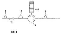
- Chromatic dispersion describes the fact that the speed of signal propagation in the fiber depends on the wavelength of the light. The consequence is that as the signal propagates through a long length of fiber, the edges of the waveform of the signal start to become more rounded. Eventually, the adjacent bits start to overlap in time causing the digital waveform to have poor readability. The amount of signal rounding depends beyond other parameters on the amount of chromatic dispersion in the cable.
- Fig. 1 shows the original pulse 1 that is broadened to a spreaded pulse 2 while traveling through a fiber 3.
- a chirped Bragg grating 5 is introduced in the path of the pulse 2.
- the resulting pulse 6 has the original shape of pulse 1 again.
- chromatic dispersion is accomplished by analyzing the group delay through the fiber as a function of wavelength.
- a wavelength tunable optical source such as a tunable laser is used to generate coherent light at different wavelengths.
- the wavelength of the tunable laser is then incremented step by step and for each wavelength step a group delay is determined.
- the group delay details are used to calculate the chromatic dispersion coefficient.
- the disadvantage of measuring the group delays step by step is the time, which is needed to perform all the wavelength steps and the respective measurements. In other words this means it takes quite a long time to get data, which are so precise that this precision is sufficient for the needs of the telecommunication industry.
- the main advantage of the present invention is that it is possible to measure the group delay and therefore the chromatic dispersion of an optical device, such as a fiber or a chirped Bragg grating, in a short amount of time while still keeping the precision of the data high enough for the needs of the telecommunication industry.
- This goal is reached by the invention by tuning the frequency of the coherent light beam of the laser from a maximum to a minimum of a given frequency range in a given time interval, e.g. making a wavelength sweep through the given wavelength range. Because of the inventive correction of effects caused by a non-linearity in the tuning of the laser this sweep can be done without detrimental broadening of the resulting spectral width.
- Method and apparatus of the invention avoid the aforementioned problems of the prior art and provide for exact data well keeping the measurement time low.
- a filtering of the Fourier transformed first signal with a high pass filter. It is further preferred to use a Hanning window as a shape for the high pass filter. Using this filter makes sure that a good elimination of not usable data is possible while still having important parts of data at the edges of the spectrum within the filter. Moreover, it is preferred to use a half of a Hanning window as a shape for the high-pass filter.
- this high pass filter is adapted to the precision and the shape of the resulting spectrum of the signal corrected for a non-linearity of the laser by making an interferometric signal out of the corrected first phase signal, Fourier transforming the interferometric signal to get a spectral signal, determining a fraction of the maximum of the spectral signal, determining the abscissas of the intersections of the ordinate of the fraction which the curve of the spectral signal, determining the mean frequency f mean as the average of the abscissas, band pass filtering the spectral signal with a band pass filter having its center at the mean frequency and having a width greater than the width of the frequency range.
- the inventive concept of adaptive filtering of the signal corrected for a non-linearity of the laser is doubling the inventive success since by eliminating the non-linearity the resulting peak of the Fourier transformed spectrum is very sharp so that it can be used a filter width which is very much smaller than known filter width in the prior art.
- this inventive concept is resulting in very smooth curves showing the group delay.
- coherence in this application means that the coherence length of the light beam is bigger than the difference of the path of the first and second and third and fourth light beams, respectively.
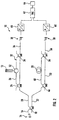
- Fig. 2 shows a schematic illustration of a preferred embodiment of an apparatus 10 for interferometric determination of the group delay of a chirped Bragg grating 12 as a device under test.
- optical properties e.g. the group delay ,of other devices, e.g. fibers or even air, also.
- the apparatus 10 comprises a tunable laser 14 as a signal source for a coherent laser beam 16, wherein the laser 14 is tunable between 1400 nm and at most 1600nm.
- the tunable laser 14 can be tuned continuously within a given frequency range in a given time interval.
- the laser beam 16 is coupled into a first beam splitter 18, which splits the coherent laser beam 16 in a first initial beam 20 and a second initial beam 22.
- the first initial beam 20 is coupled into a second beam splitter 24. With the help of the second beam splitter 24 the first initial beam 20 is split into a first beam 26 and a second beam 28.
- the first beam 26 is traveling a different and longer path than the second beam 28, since the first beam 26 is coupled via a circulator 52 into the grating 12.
- the first beam 26 is coupled via the circulator 52 in the first path 32 of the first beam 26 again. Then the first beam 26 and the second beam 28 are united with a third beam splitter 34 by superimposing the first beam 26 and the second beam 28 to a first resulting beam 36.
- the first resulting beam 36 is coupled into a first photodiode 38.
- the photodiode 38 transmits its output as a first signal to an analog/digital-converter (ADC) 40 (which can be National Instruments AD-MIO-16DE-10).
- ADC 40 is connected to a transient recorder 42 that can be a FAST TR1202 of Fast Comtec GmbH, Germany.
- the laser 14 can be a HP81680A of the applicant.
- the transient recorder 42 is coupled to a computer 44 as an evaluation unit of apparatus 10.
- Second beam splitter 24, first beam 26, second beam 28 and third beam splitter 34 built up a first Mach-Zehnder-interferometer.
- Exiting the first beam splitter 18 is a second initial beam 22.
- a fourth beam splitter 46 splits the second initial beam 22 into a third beam 48 traveling a third path and a fourth beam 50.
- the third beam 48 is traveling a different and longer path than the fourth beam 50, wherein the path length of the third path differs from the path length of the fourth path by more than 1 m, preferred by less than 20 m, more preferred by less than 9 m, even more preferred between 7 and 9 m. This different path is symbolized by some loops 30.
- the third 48 and the fourth 50 beam are coupled into a fifth beam splitter 54 which units the third beam 48 and the fourth beam 50 to a superimposed second resulting beam 56.
- the second resulting beam 56 is then coupled into a second photodiode 58.
- the second photodiode 58 transmits its output as a second signal to an analog/digital converter ADC 60, similar to the ADC 40.
- the ADC 60 is also connected to the transient receiver 42.
- Fourth beam splitter 46, third beam 48, fourth beam 50 and fifth beam splitter 54 built up a second Mach-Zehnder interferometer.
- the system for determination of the group delay of the optical component 12 according to the present invention is based on the use of aforementioned Mach-Zehnder interferometers, both of which are supplied with light of the same light source 14. It is necessary to make the determination by interferometric measurements since the phase characteristics of the component 12 can not be detected directly.
- n the refractive index of the medium
- ⁇ L the difference of the path length
- c the velocity of light
- the detected voltage is determined by the two superimposed fields that travel through the different paths of the interferometer:
- the second signal of the second interferometer is therefore ideally, i.e. with a linear rise in frequency of the laser 14 over time a cosine, the frequency of which is determined by the length ⁇ L and the sweep velocity of the wavelength over time.
- the laser 14 will produce not an ideal sweep over the given frequency range and will produce non linearities in this sweep one can expect a cosine which has a frequency which is changing over time.
- this second signal it is possible according to the present invention to correct the first signal of the first interferometer for this non-linearities in therefore getting a resulting corrected first signal as if the laser 14 had performed a linear sweep.
- the group delay of this grating 12 is determined.
- the detected power of the first photodiode 38 is calculated in an analog way as explained above.
- the first signal is only determined in its dependency of the optical frequency ⁇ , where as the time dependency is determined later on.
- ⁇ DUT ( v ) ⁇ DUT ( v 0 ) + ⁇ DUT ( v 0 ) ⁇ 2 ⁇ ( v - v 0 ) + 1 2 d dv ( ⁇ DUT ( v ))
- v v 0 ⁇ 2 ⁇ ( v - v 0 ) 2 + ⁇ with
- ⁇ det ⁇ DUT ( v 0 )- ⁇ ( v 0 ) + 2 ⁇ [ ⁇ DUT ( v 0 )- ⁇ ( v 0 )] ⁇ ( v - v 0 ) - d ⁇ d ⁇
- ⁇ 0 ⁇ ⁇ 2 c ⁇ ( v - v 0 ) 2 + ⁇ ⁇ 0 +2 ⁇ 0 ⁇ ( v - v 0 ) - d ⁇ d ⁇
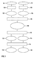
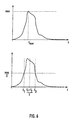
- Fig. 3 ovals describe signals and boxes describe measures of the evaluation unit 44.
- First of all the second or reference signal 56 and the first signal 36 are towed to the zero line in step 100 (see Fig. 4).
- the resulting signals 102 and 104 are now oscillating about the zero line.
- step 106 any non-linearities in the sweep of the laser 14 are corrected with the help of the second signal 56 (see Fig. 5).
- Resulting is a signal 108 corrected for any non-linearities in the laser sweep.
- the group delay 112 and the linear deviation of linear chirp 114 are evaluated in step 110 a signal delay 112 and the linear deviation of linear chirp 114.
- a filter step 116 it is possible to get filtered signals 118 and 120 of the group delay and of the deviation from the linear chirp of the grating 12.
- FIG. 4 the principle of the function 100 is graphically illustrated.
- A is the amplitude of the signals 36 and 56.
- 152 denotes the reflection spectrum of the grating 12.
- 124 denotes the ideal center line of the spectrum 122.
- the function 100 is illustrated in Fig. 8 and comprises the following steps:
- FIG. 5 illustrates a part of the function of step 106 to correct unwitting non-linearities in the sweep of the laser 14.
- the step 106 comprises the following steps (in the following the symbol “f” is used instead of " ⁇ "):
- the resulting signal 108 which is corrected for any non linearities in the sweep of the laser 14 is used in step 110 for evaluate the group delay 112 and the deviation 114 from the linear chirp of the grating 12.
- This evaluation is done with the help of the above-mentioned mathematical formulas and can comprises deriving a group delay 112 of the optical device under test 12 by differentiating the compensated first phase signal with respect to the frequency.
- the method can further comprise the following steps:
- this filter step is preferably performed before the calculating of the group delay 112, as follows:
- Resulting is a filtered group delay 118 and a filtered deviation 120.
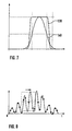
- Figure 6 shows the principle of determination of the center frequency f mean of the interferometric spectrum.
- Figure 7 shows a graph showing different filter shapes for use with the inventive method, a flat top filter shape 130 and a Hanning form filter shape 140.
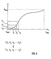
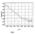
- Figure 9 shows the group delay 112 over wave length of a chirped Bragg grating 12, which is a FBGDC-HP1A of the company JDS Fitel. It is clearly seen that the graph of the group delay 112 is very smooth with respect to graphs determined with methods of the prior art.
Claims (40)
- Un procédé de détermination d'une propriété d'un dispositif optique (12) en cours de test, qui comprend les étapes consistant à:utiliser un premier faisceau lumineux cohérent initial (20),modifier une première propriété initiale du premier faisceau lumineux initial (20),coupler le premier faisceau lumineux initial (20) au dispositif (12) en cours de test,détecter un premier signal du premier faisceau lumineux initial (20) reçu du dispositif en cours de test (12),corriger une non-linéarité du premier signal provoquée par une non-linéarité de la modification de la première propriété initiale en interpolant le premier signal sur une échelle linéaire.
- Le procédé selon la revendication 1, qui comprend en outre les étapes consistant à:utiliser un deuxième faisceau lumineux cohérent initial (22),modifier une deuxième propriété initiale du deuxième faisceau lumineux initial (22),détecter un deuxième signal du deuxième faisceau lumineux initial (22) sans le coupler au dispositif (12) en cours de test, afin de découvrir une non-linéarité du deuxième signal provoquée par une non-linéarité de la modification de la deuxième propriété initiale,utiliser la non-linéarité découverte du deuxième signal détecté pour interpoler le premier signal.
- Le procédé selon la revendication 1 ou 2, qui comprend en outre les étapes consistant à:produire un faisceau lumineux cohérent (16),diviser le faisceau lumineux cohérent (16) en un premier faisceau lumineux initial (20) et un deuxième faisceau lumineux initial (22).
- Le procédé selon l'une quelconque des revendications précédentes, qui comprend en outre l'étape consistant à:détecter simultanément la première propriété résultante et la deuxième propriété résultante.
- Le procédé selon l'une quelconque des revendications précédentes, qui comprend en outre l'étape consistant à:modifier simultanément la première propriété initiale et la deuxième propriété initiale.
- Le procédé selon l'une quelconque des revendications précédentes,
dans lequel la première propriété initiale et la deuxième propriété initiale sont la même propriété initiale. - Le procédé selon l'une quelconque des revendications précédentes,
dans lequel la propriété initiale est la fréquence du faisceau lumineux cohérent (16). - Le procédé selon l'une quelconque des revendications précédentes, qui comprend en outre les étapes consistant à:transformer le premier signal en un certain nombre de signaux de phase sur une échelle linéaire d'un certain nombre d'instants,transformer le deuxième signal en un certain nombre de signaux de fréquence sur la même échelle linéaire d'instants pour découvrir une non-linéarité du deuxième signal provoquée par une non-linéarité de la modification de la propriété initiale, la propriété initiale étant la fréquence de la lumière cohérente,assigner le premier signal transformé au deuxième signal transformé,interpoler le premier signal transformé assigné sur une échelle linéaire de fréquences.
- Le procédé selon la revendication 8 qui comprend en outre les étapes consistant à:créer l'échelle linéaire de fréquences flin(n) selon la formule
- Le procédé selon l'une quelconque des revendications précédentes, qui comprend les étapes consistant à:diviser le premier faisceau lumineux initial (20) en un premier faisceau lumineux (26) et un deuxième faisceau lumineux (28),coupler le premier faisceau lumineux (26) au dispositif optique (12) en cours de test,amener le deuxième faisceau lumineux (28) à parcourir un trajet différent de celui du premier faisceau lumineux (26),superposer le premier (26) et le deuxième (28) faisceaux lumineux pour produire dans un premier faisceau lumineux résultant superposé (36) une interférence entre le premier faisceau lumineux (26) et le deuxième faisceau lumineux (28),détecter comme premier signal la puissance du premier faisceau lumineux superposé (36) en fonction du temps lors de l'accord de la fréquence du faisceau lumineux cohérent (16) à partir d'un minimum jusqu'à un maximum d'une plage donnée de fréquences dans un intervalle de temps donné,diviser le deuxième faisceau lumineux initial (22) en un troisième faisceau lumineux (48) et un quatrième faisceau lumineux (50),superposer le troisième faisceau lumineux (48) et le quatrième faisceau lumineux (50) lorsque chaque faisceau lumineux (48, 50) a parcouru un trajet différent, afin de produire dans un deuxième faisceau lumineux résultant superposé (56) une interférence entre le troisième (48) et le quatrième (50) faisceaux lumineux,détecter comme deuxième signal la puissance du deuxième faisceau lumineux superposé (56) en fonction du temps lors de l'accord de la fréquence du faisceau lumineux cohérent (16) à partir d'un maximum jusqu'à un minimum d'une plage donnée de fréquences dans un intervalle de temps donné,utiliser le deuxième signal détecté pour dériver une information de non-linéarité concernant une non-linéarité d'un gradient d'accord de la fréquence lors de l'accord de la fréquence du faisceau lumineux cohérent (16) à partir du maximum jusqu'au minimum de la plage donnée de fréquences, etutiliser l'information de non-linéarité pour corriger des effets provoqués sur le premier signal par la non-linéarité, pour obtenir un premier signal corrigé (108).
- Le procédé selon l'une quelconque des revendications précédentes, qui comprend en outre les étapes consistant à:dériver l'information de non-linéarité en:transformant le deuxième signal pour obtenir un deuxième signal transformé de Fourier,éliminant les parties négatives du deuxième signal transformé de Fourier pour obtenir un deuxième signal non négatif transformé de Fourier,retransformer le deuxième signal non négatif transformé de Fourier pour obtenir un signal analytique du deuxième signal,déterminer la phase du signal analytique pour obtenir comme deuxième signal de phase la phase du deuxième signal en fonction du temps,utiliser le deuxième signal de phase pour déterminer comme information de non-linéarité la fréquence du deuxième signal en fonction du temps.
- Le procédé selon l'une quelconque des revendications précédentes, qui comprend en outre les étapes consistant à:dériver un premier signal de phase en:transformant le premier signal pour obtenir un premier signal transformé de Fourier,éliminant les parties négatives du premier signal transformé de Fourier pour obtenir un premier signal non négatif transformé de Fourier,retransformer le premier signal non négatif transformé de Fourier pour obtenir un signal analytique du premier signal,déterminer la phase du signal analytique pour obtenir comme premier signal de phase la phase du deuxième signal en fonction du temps.
- Le procédé selon l'une quelconque des revendications précédentes, qui comprend en outre les étapes consistant à:corriger les effets provoqués par la non-linéarité sur le premier signal en:utilisant l'information de non-linéarité pour interpoler le premier signal de phase du premier signal sur une échelle linéaire de fréquences pour obtenir un premier signal de phase corrigé.
- Le procédé selon l'une quelconque des revendications précédentes, qui comprend en outre les étapes consistant à:déterminer la fréquence f(n) du deuxième signal en fonction de n instants discrets, n = 1, ..., N, sur la base du deuxième signal de phase pour déterminer l'information de non-linéarité en:déterminant le deuxième signal de phase (n) aux n instants,déterminant le maximum max du deuxième signal de phaseutilisant une fréquence maximale prédéterminée fmax de la plage des fréquences, une vitesse moyenne prédéterminée d'accord pendant l'accord de la fréquence et le maximum max du deuxième signal de phase pour déterminer la fréquence f(n) pour chacun des n instants selon la formule: f(n) = [(fmax - fmin)/max] (n).
- Le procédé selon l'une quelconque des revendications précédentes, qui comprend en outre les étapes consistant à:obtenir l'échelle linéaire flin(n) de fréquences en:utilisant la fréquence maximale prédéterminée fmax de la plage des fréquences et la fréquence minimale prédéterminée fmin de la plage des fréquences pour déterminer l'échelle linéaire flin(n) de fréquences selon la formule: flin(n) = [(fmax - fmin) / (N-1)]n,trier de préférence de façon monotone les valeurs absolues de f(n).
- Le procédé selon l'une quelconque des revendications précédentes, qui comprend en outre les étapes consistant à:utiliser f(n) pour interpoler le premier signal de phase du premier signal sur l'échelle linéaire de fréquences flin(n).
- Le procédé selon l'une quelconque des revendications précédentes, qui comprend en outre les étapes consistant à:dériver, à partir du premier signal compensé, des propriétés de transmission et/ou de réflexion du dispositif optique en cours de test.
- Le procédé selon l'une quelconque des revendications précédentes, qui comprend en outre au moins l'une des étapes consistant à:dériver du premier signal corrigé (108) un retard (112) de groupe du dispositif optique (12) en cours de test en tant que fonction de la fréquence,dériver du premier signal corrigé (108) le coefficient de dispersion chromatique du dispositif optique (12) en cours de test en fonction de la fréquence.
- Le procédé selon l'une quelconque des revendications précédentes, qui comprend en outre les étapes consistant à:dériver un retard (112) de groupe du dispositif optique (12) en cours de test en différenciant par rapport à la fréquence le premier signal de phase corrigé.
- Le procédé selon l'une quelconque des revendications précédentes, qui comprend en outre les étapes consistant à:ignorer au début de l'accord une quantité prédéterminée de valeurs du premier signal de phase corrigé pour éliminer, hors du premier signal corrigé (108), des défauts initiaux, appelés classiquement "maladies infantiles".
- Le procédé selon l'une quelconque des revendications précédentes, qui comprend en outre les étapes consistant à:approcher par des polynômes du deuxième degré au moins le retard (112) de groupe pour obtenir un retard approché de groupe,soustraire du retard (112) de groupe le retard approché de groupe pour obtenir une partie non linéaire du retard (112) de groupe.
- Le procédé selon l'une quelconque des revendications précédentes, qui comprend en outre les étapes consistant à:utiliser la partie non-linéaire du retard de groupe pour déterminer, pour le dispositif (12) en cours de test, la puissance moyenne de signal d'un écart par rapport à un retard linéaire de groupe.
- Le procédé selon l'une quelconque des revendications précédentes, qui comprend en outre l'étape consistant à:utiliser le coefficient du terme au carré pour déterminer le gradient moyen du retard (112) de groupe.
- Le procédé selon l'une quelconque des revendications précédentes, qui comprend en outre les étapes consistant à:amener le premier signal à osciller autour d'une ligne de zéro en:déterminant les points de valeur moyenne du premier signal,interpolant une courbe qui passe par ces points,soustrayant du premier signal les valeurs de la courbe pour obtenir un premier signal corrigé qui oscille autour de la ligne de zéro.
- Le procédé selon l'une quelconque des revendications précédentes, qui comprend en outre les étapes consistant à:déterminer les points de valeur moyenne en extrayant tous les points à gradient maximal.
- Le procédé selon l'une quelconque des revendications précédentes, qui comprend en outre les étapes consistant à:amener le premier signal à osciller autour d'une ligne de zéro en:déterminant les points de valeur moyenne du premier signal,déterminant le maximum et le minimum du premier signal dans une première plage de temps prédéterminée plus petite que la plage de temps totale,déterminer une valeur moyenne entre le maximum et le minimum,déterminer le maximum et le minimum du premier signal dans une plage de temps prédéterminée suivante adjacente à la plage de temps déjà examinée,déterminer une valeur moyenne entre le maximum et le minimum,répéter les deux dernières étapes jusqu'à ce que l'intervalle de temps complet ait été couvert.
- Le procédé selon l'une quelconque des revendications précédentes, qui comprend en outre les étapes consistant à:choisir la plage de temps prédéterminée en:déterminant la période moyenne des oscillations du premier signal,choisir la dimension de la plage d'une façon telle que plus de deux périodes moyennes sont incluses dans la plage de temps choisie.
- Le procédé selon l'une quelconque des revendications précédentes, qui comprend en outre les étapes consistant à:déterminer les points de valeur moyenne en:déterminant le maximum du signal transformé de Fourier du premier signal,utilisant le maximum pour déterminer une dimension d'un filtre passe-haut,filtrant le premier signal transformé de Fourier au moyen du filtre passe-haut.
- Un procédé de détermination d'une propriété d'un dispositif optique (12) en cours de test, qui comprend en outre les étapes consistant à:détecter une modification d'un signal au cours du temps, qui est la base de la dérivation de la propriété,filtrer le signal détecté en:transformant le signal détecté pour obtenir un signal transformée de Fourier,filtrer le signal transformée de Fourier au moyen d'un filtre pour obtenir un signal transformé de Fourier filtré,retransformer le signal transformé de Fourier filtré pour obtenir un signal filtré,dériver la propriété sur la base du signal filtré.
- Le procédé selon la revendication 29, qui comprend en outre les étapes consistant à:corriger le signal détecté quant à une non-linéarité par le procédé de l'une quelconque des revendications 1 à 28 pour obtenir un premier signal corrigé (108).
- Le procédé selon l'une quelconque des revendications précédentes, qui comprend en outre les étapes consistant à:utiliser le premier signal corrigé pour calculer le premier signal de phase corrigé en fonction de la fréquence,filtrer le premier signal de phase corrigé en:exécutant sur celui-ci une transformée de Hilbert avant de le filtrer pour obtenir un signal corrigé à filtrer selon les étapes de la revendication 29 ou 30.
- Le procédé selon l'une quelconque des revendications précédentes, qui comprend en outre les étapes consistant à:filtrer le premier signal corrigé (108) avant de calculer le retard (112) de groupe.
- Le procédé selon l'une quelconque des revendications précédentes, qui comprend en outre les étapes consistant à:adapter le filtrage à la configuration du premier signal corrigé (108) en:a: réalisant un signal interféromètrique à partir du premier signal de phase corrigé,b: appliquant une transformée de Fourier au signal interférométrique pour obtenir un signal spectral,c: déterminant une fraction, de préférence la moitié, du maximum du signal spectral,d: déterminant les abscisses des intersections de l'ordonnée de la fraction avec la courbe du signal spectral,e: déterminant la fréquence moyenne fmoy en tant que moyenne des abscisses,f: filtrant passe-bande le signal spectral au moyen d'un filtre passe-bande dont le centre est à la fréquence moyenne et dont la largeur est plus grande que la largeur de la plage des fréquences.
- Le procédé selon l'une quelconque des revendications précédentes, qui comprend en outre les étapes consistant à:déterminer la largeur du filtre passe-bande ena: prédéterminant ou estimant la plage maximale GDplage du retard de groupe,b: déterminant la valeur moyenne GDmoy du retard de groupe au moyen des étapes c à e de la revendication 33,c: calculant la largeur du filtre au moyen de la formule: largeur de filtre = fmoy (GDplage/ GDmoy).
- Le procédé selon l'une quelconque des revendications précédentes, qui comprend en outre les étapes consistant à:soustraire du retard de groupe un gradient dans le groupe de retard,prédéterminer la plage maximale GDplage du retard de groupe,mettre en oeuvre les étapes b et c de la revendication 34,calculer le retard du groupe,ajouter au retard de groupe calculé le gradient soustrait.
- Un programme ou produit de logiciel, enregistré de préférence sur un support de données, pour mettre en oeuvre le procédé selon l'une quelconque des revendications précédentes lorsqu'il fonctionne sur un système de traitement de données comme un ordinateur.
- Un appareil de détermination de propriétés d'un dispositif optique en cours de test, qui comprend:un premier diviseur (18) de faisceau dans un trajet d'un faisceau lumineux cohérent (16) pour diviser le faisceau lumineux cohérent (16) en un premier faisceau lumineux initial (20) qui parcourt un premier trajet initial et en un deuxième faisceau lumineux initial (22) qui parcourt un deuxième trajet initial,un deuxième diviseur (24) de faisceau situé dans ce premier trajet initial pour diviser le premier faisceau lumineux initial (20) en un premier faisceau lumineux (26) qui parcourt un premier trajet (32) et en un deuxième faisceau lumineux (28) qui parcourt un deuxième trajet,un emplacement dans le premier trajet (32) pour coupler le premier faisceau lumineux (26) au dispositif optique (12) en cours de test,un troisième diviseur (34) de faisceau situé dans ce premier (32) et ce deuxième trajets pour superposer le premier (26) et le deuxième (28) faisceaux lumineux lorsque le deuxième faisceau lumineux (28) a parcouru un trajet différent du premier faisceau lumineux (26) pour produire une interférence entre le premier faisceau lumineux (26) et le deuxième faisceau lumineux (28) dans un premier faisceau lumineux résultant superposé (36) qui parcourt un premier trajet résultant,un premier détecteur (38) de puissance pour détecter en continu comme premier signal la puissance du premier faisceau lumineux superposé (36) en fonction du temps lors de l'accord de la fréquence du faisceau lumineux cohérent (16) d'un minimum à un maximum d'une plage donnée de fréquences dans un intervalle de temps donné,un quatrième diviseur (46) de faisceau pour diviser le deuxième faisceau initial (22) en un troisième faisceau lumineux (48) qui parcourt un troisième trajet et un quatrième faisceau lumineux (50) qui parcourt un quatrième trajet,un cinquième diviseur (54) de faisceau dans ce troisième et ce quatrième trajets pour superposer le troisième faisceau lumineux (48) et le quatrième faisceau lumineux (50) lorsque chaque faisceau lumineux (48, 50) a parcouru un trajet différent, afin de produire une interférence entre le troisième (48) et le quatrième (50) faisceaux lumineux dans un deuxième faisceau lumineux superposé résultant (56) qui parcourt un deuxième trajet résultant,un deuxième détecteur (60) de puissance pour détecter en continu en tant que deuxième signal la puissance du deuxième faisceau lumineux superposé résultant (56) en fonction du temps lors de l'accord de la fréquence du faisceau lumineux cohérent (16) d'un maximum à un minimum d'une plage donnée de fréquences dans un intervalle de temps donné,une unité d'évaluation (44) pour dériver des propriétés optiques du dispositif optique (12) en cours de test, afin d'utiliser le deuxième signal détecté pour dériver une information de non-linéarité concernant une non-linéarité dans un gradient d'accord de la fréquence lors de l'accord de la fréquence du faisceau lumineux cohérent (16) du maximum au minimum de la plage donnée de fréquences, et pour utiliser l'information de non-linéarité afin de corriger des effets provoqués sur le premier signal par la non-linéarité afin d'obtenir un premier signal corrigé.
- L'appareil selon la revendication 37,
qui comprend en outre un moyen de calcul susceptible d'exécuter au moins l'une des étapes additionnelles conforme à l'une quelconque des revendications 2 à 36. - L'appareil selon la revendication 37 ou 38, qui comprend en outre:un circulateur (52) situé à cet emplacement dans ce premier trajet (32) pour permettre à l'appareil (10) d'examiner aussi des composants optiques de réflexion.
- L'appareil selon l'une quelconque des revendications 37 à 39,
dans lequel le deuxième diviseur (24) de faisceau, le troisième diviseur (34) et le premier détecteur (38) constituent un premier interféromètre de Mach-Zehnder,
et le quatrième diviseur (46) de faisceau et le cinquième diviseur (54) de faisceau et le deuxième détecteur (58) constituent un deuxième interféromètre de Mach-Zehnder.
Priority Applications (4)
| Application Number | Priority Date | Filing Date | Title |
|---|---|---|---|
| EP01113887A EP1191321B1 (fr) | 2001-06-07 | 2001-06-07 | Détermination des propriétés d'un dispositif optique |
| DE60100064T DE60100064T2 (de) | 2001-06-07 | 2001-06-07 | Bestimmung der Eigenschaften eines optischen Gerätes |
| US10/059,703 US6788419B2 (en) | 2001-06-07 | 2002-01-29 | Determination of properties of an optical device |
| JP2002166603A JP2003014585A (ja) | 2001-06-07 | 2002-06-07 | 光デバイスの特性の判定 |
Applications Claiming Priority (1)
| Application Number | Priority Date | Filing Date | Title |
|---|---|---|---|
| EP01113887A EP1191321B1 (fr) | 2001-06-07 | 2001-06-07 | Détermination des propriétés d'un dispositif optique |
Publications (2)
| Publication Number | Publication Date |
|---|---|
| EP1191321A1 EP1191321A1 (fr) | 2002-03-27 |
| EP1191321B1 true EP1191321B1 (fr) | 2002-12-11 |
Family
ID=8177664
Family Applications (1)
| Application Number | Title | Priority Date | Filing Date |
|---|---|---|---|
| EP01113887A Expired - Lifetime EP1191321B1 (fr) | 2001-06-07 | 2001-06-07 | Détermination des propriétés d'un dispositif optique |
Country Status (4)
| Country | Link |
|---|---|
| US (1) | US6788419B2 (fr) |
| EP (1) | EP1191321B1 (fr) |
| JP (1) | JP2003014585A (fr) |
| DE (1) | DE60100064T2 (fr) |
Families Citing this family (61)
| Publication number | Priority date | Publication date | Assignee | Title |
|---|---|---|---|---|
| JP4241038B2 (ja) | 2000-10-30 | 2009-03-18 | ザ ジェネラル ホスピタル コーポレーション | 組織分析のための光学的な方法及びシステム |
| JP3974792B2 (ja) * | 2002-02-07 | 2007-09-12 | 富士通株式会社 | 光導波路デバイス及び光デバイス |
| US7567349B2 (en) | 2003-03-31 | 2009-07-28 | The General Hospital Corporation | Speckle reduction in optical coherence tomography by path length encoded angular compounding |
| ATE350656T1 (de) | 2003-02-21 | 2007-01-15 | Thorlabs Inc | Vorrichtung und verfahren zur bestimmung der chromatischen dispersion von optischen komponenten |
| ES2310744T3 (es) | 2003-06-06 | 2009-01-16 | The General Hospital Corporation | Fuente de luz sintonizable en longitudes de onda. |
| US7447408B2 (en) | 2004-07-02 | 2008-11-04 | The General Hospital Corproation | Imaging system and related techniques |
| EP1793731B1 (fr) | 2004-08-24 | 2013-12-25 | The General Hospital Corporation | Appareil d'imagerie comprenant un dispositif de distribution de fluide et un dispositif de rétraction |
| EP1989997A1 (fr) | 2004-08-24 | 2008-11-12 | The General Hospital Corporation | Procèdé, Système et logiciel pour la mesure de la contrainte mécanique et des propriétés élastiques d'un echantillon |
| WO2006058346A1 (fr) | 2004-11-29 | 2006-06-01 | The General Hospital Corporation | Ensembles, dispositifs, endoscopes, catheters et methodes d'imagerie optique permettant d'eclairer et de detecter simultanement plusieurs points sur un echantillon |
| US7426021B2 (en) * | 2004-11-29 | 2008-09-16 | Expo Electro- Optical Engineering Inc. | Interferometric optical analyzer and method for measuring the linear response of an optical component |
| US8315282B2 (en) | 2005-01-20 | 2012-11-20 | Massachusetts Institute Of Technology | Fourier domain mode locking: method and apparatus for control and improved performance |
| ATE451669T1 (de) | 2005-04-28 | 2009-12-15 | Gen Hospital Corp | Bewertung von bildmerkmalen einer anatomischen struktur in optischen kohärenztomographiebildern |
| EP1889037A2 (fr) | 2005-06-01 | 2008-02-20 | The General Hospital Corporation | Appareil, methode et systeme pour effectuer une imagerie de domaine de frequence optique a resolution de phase |
| JP4714882B2 (ja) * | 2005-07-01 | 2011-06-29 | 国立大学法人山梨大学 | ブラッググレーティングの構造の同定方法および装置ならびにその作成方法 |
| EP2267404B1 (fr) | 2005-08-09 | 2016-10-05 | The General Hospital Corporation | Dispositif et procédé servant a effectuer une démodulation en quadrature à base de polarisation en tomographie à cohérence optique |
| US7872759B2 (en) | 2005-09-29 | 2011-01-18 | The General Hospital Corporation | Arrangements and methods for providing multimodality microscopic imaging of one or more biological structures |
| EP1945094B1 (fr) * | 2005-10-14 | 2018-09-05 | The General Hospital Corporation | Imagerie fluorescente codee par frequence et par spectre |
| US8145018B2 (en) | 2006-01-19 | 2012-03-27 | The General Hospital Corporation | Apparatus for obtaining information for a structure using spectrally-encoded endoscopy techniques and methods for producing one or more optical arrangements |
| EP2289397A3 (fr) | 2006-01-19 | 2011-04-06 | The General Hospital Corporation | Procédés et systèmes pour visualiser de manière optique des organes intracavitaires épithéliaux lors d'un balayage au faisceau |
| US10426548B2 (en) | 2006-02-01 | 2019-10-01 | The General Hosppital Corporation | Methods and systems for providing electromagnetic radiation to at least one portion of a sample using conformal laser therapy procedures |
| EP1986545A2 (fr) | 2006-02-01 | 2008-11-05 | The General Hospital Corporation | Appareil destiné à appliquer une pluralité de rayonnements électromagnétiques à un échantillon |
| EP2306141A1 (fr) | 2006-02-24 | 2011-04-06 | The General Hospital Corporation | Procédés et systèmes destinés à réaliser une tomographie par cohérence optique dans le domaine de Fourier avec résolution angulaire |
| US8175685B2 (en) | 2006-05-10 | 2012-05-08 | The General Hospital Corporation | Process, arrangements and systems for providing frequency domain imaging of a sample |
| WO2008049118A2 (fr) | 2006-10-19 | 2008-04-24 | The General Hospital Corporation | Dispositif et procédé d'obtention et de fourniture d'informations d'image associées à au moins une portion d' échantillon et permettant de réaliser une telle portion |
| US7617830B2 (en) * | 2006-10-31 | 2009-11-17 | Resurgent Health & Medical, Llc | Wash chamber for automated appendage-washing apparatus |
| US9176319B2 (en) | 2007-03-23 | 2015-11-03 | The General Hospital Corporation | Methods, arrangements and apparatus for utilizing a wavelength-swept laser using angular scanning and dispersion procedures |
| WO2008121844A1 (fr) | 2007-03-30 | 2008-10-09 | The General Hospital Corporation | Système et procédé pour fournir une imagerie à granularité laser en vue de détecter une plaque à risque |
| EP2309923B1 (fr) | 2008-07-14 | 2020-11-25 | The General Hospital Corporation | Appareil et procédés d'endoscopie couleur |
| WO2010068764A2 (fr) | 2008-12-10 | 2010-06-17 | The General Hospital Corporation | Systèmes, appareil et procédés d'extension de la plage de profondeur d'imagerie de tomographie par cohérence optique, par le biais du sous-échantillonnage optique |
| JP2012515576A (ja) | 2009-01-20 | 2012-07-12 | ザ ジェネラル ホスピタル コーポレイション | 内視鏡生検装置、システム、及び方法 |
| WO2010091190A2 (fr) | 2009-02-04 | 2010-08-12 | The General Hospital Corporation | Appareil et procédé d'utilisation d'une source d'ajustement de longueur d'onde optique à grande vitesse |
| JP5819823B2 (ja) | 2009-07-14 | 2015-11-24 | ザ ジェネラル ホスピタル コーポレイション | 血管の内部の流れおよび圧力を測定する装置および装置の作動方法 |
| PT2542145T (pt) | 2010-03-05 | 2020-11-04 | Massachusetts Gen Hospital | Sistemas, métodos e meios acessíveis por computador que proporcionam imagens microscópicas de pelo menos uma estrutura anatómica numa resolução particular |
| US9069130B2 (en) | 2010-05-03 | 2015-06-30 | The General Hospital Corporation | Apparatus, method and system for generating optical radiation from biological gain media |
| US9557154B2 (en) | 2010-05-25 | 2017-01-31 | The General Hospital Corporation | Systems, devices, methods, apparatus and computer-accessible media for providing optical imaging of structures and compositions |
| EP2575598A2 (fr) | 2010-05-25 | 2013-04-10 | The General Hospital Corporation | Appareil, systèmes, procédés et support accessible par ordinateur pour l'analyse spectrale d'images de tomographie par cohérence optique |
| US10285568B2 (en) | 2010-06-03 | 2019-05-14 | The General Hospital Corporation | Apparatus and method for devices for imaging structures in or at one or more luminal organs |
| WO2012058381A2 (fr) | 2010-10-27 | 2012-05-03 | The General Hospital Corporation | Appareil, systèmes et méthodes de mesure de la pression sanguine dans au moins un vaisseau |
| JP2014523536A (ja) | 2011-07-19 | 2014-09-11 | ザ ジェネラル ホスピタル コーポレイション | 光コヒーレンストモグラフィーにおいて偏波モード分散補償を提供するためのシステム、方法、装置およびコンピュータアクセス可能な媒体 |
| WO2013066631A1 (fr) | 2011-10-18 | 2013-05-10 | The General Hospital Corporation | Appareil et procédés de production et/ou d'utilisation de retard(s) optique(s) de recirculation |
| WO2013148306A1 (fr) | 2012-03-30 | 2013-10-03 | The General Hospital Corporation | Système d'imagerie, procédé et fixation distale permettant une endoscopie à champ de vision multidirectionnel |
| EP2852315A4 (fr) | 2012-05-21 | 2016-06-08 | Gen Hospital Corp | Appareil, dispositif et procédé pour microscopie par capsule |
| EP2888616A4 (fr) | 2012-08-22 | 2016-04-27 | Gen Hospital Corp | Système, procédé et support accessible par ordinateur pour fabriquer des endoscopes miniatures à l'aide d'une lithographie douce |
| WO2014117130A1 (fr) | 2013-01-28 | 2014-07-31 | The General Hospital Corporation | Appareil et procédé devant fournir une spectroscopie diffuse co-enregistrée avec imagerie de domaine de fréquence optique |
| US10893806B2 (en) | 2013-01-29 | 2021-01-19 | The General Hospital Corporation | Apparatus, systems and methods for providing information regarding the aortic valve |
| US11179028B2 (en) | 2013-02-01 | 2021-11-23 | The General Hospital Corporation | Objective lens arrangement for confocal endomicroscopy |
| JP6378311B2 (ja) | 2013-03-15 | 2018-08-22 | ザ ジェネラル ホスピタル コーポレイション | 物体を特徴付ける方法とシステム |
| WO2014186353A1 (fr) | 2013-05-13 | 2014-11-20 | The General Hospital Corporation | Détection de la phase et de l'amplitude d'une fluorescence auto-interférente |
| WO2015009932A1 (fr) | 2013-07-19 | 2015-01-22 | The General Hospital Corporation | Appareil d'imagerie et procédé utilisant une endoscopie à champ de vision multidirectionnel |
| EP3021735A4 (fr) | 2013-07-19 | 2017-04-19 | The General Hospital Corporation | Détermination de mouvement oculaire au moyen d'une imagerie de la rétine avec rétroaction d'un mouvement de l'oeil par imagerie de la rétine et fournir des informations en retour pour l'acquisition de signaux venant de la rétine |
| EP3025173B1 (fr) | 2013-07-26 | 2021-07-07 | The General Hospital Corporation | Appareil avec dispositif laser utilisant de la dispersion optique pour applications en tomographie en cohérence optique dans le domaine de fourier |
| US9733460B2 (en) | 2014-01-08 | 2017-08-15 | The General Hospital Corporation | Method and apparatus for microscopic imaging |
| WO2015116986A2 (fr) | 2014-01-31 | 2015-08-06 | The General Hospital Corporation | Système et procédé pour faciliter une imagerie volumétrique manuelle et/ou automatique avec un retour de tension ou d'effort en temps réel au moyen d'un dispositif d'imagerie amarré |
| WO2015153982A1 (fr) | 2014-04-04 | 2015-10-08 | The General Hospital Corporation | Appareil et procédé de commande de la propagation et/ou de la transmission d'un rayonnement électromagnétique dans un ou des guides d'ondes flexibles |
| WO2015157911A1 (fr) * | 2014-04-15 | 2015-10-22 | 华为技术有限公司 | Dispositif de mesure de retard de vitesse d'un groupe de guides d'ondes optiques et procédé |
| PL225163B1 (pl) * | 2014-04-15 | 2017-02-28 | Orange Polska Spółka Akcyjna | Sposób pomiaru współczynnika dyspersji chromatycznej światłowodu optycznego |
| ES2907287T3 (es) | 2014-07-25 | 2022-04-22 | Massachusetts Gen Hospital | Aparato para imagenología y diagnóstico in vivo |
| KR101817332B1 (ko) * | 2015-09-14 | 2018-01-10 | 연세대학교 산학협력단 | 펄스레이저 광학 시스템에서 디지털 오실로스코프를 이용한 시간 정보 측정방법 |
| WO2017079596A1 (fr) * | 2015-11-06 | 2017-05-11 | Ap Robotics, Llc | Mesure de distance interférométrique en fonction de la compression d'un interférogramme à fluctuation de longueur d'onde à partir d'une interférence à fluctuation de longueur d'onde croisée |
| DE102017011730B4 (de) * | 2017-12-18 | 2020-06-18 | Hottinger Baldwin Messtechnik Gmbh | Interrogator für zwei Faser-Bragg-Gitter Messstellen |
| CN113804404B (zh) * | 2021-08-16 | 2023-05-05 | 广东工业大学 | 一种用于光频域偏振串音测量的光源扫频非线性校正方法 |
Family Cites Families (4)
| Publication number | Priority date | Publication date | Assignee | Title |
|---|---|---|---|---|
| US4556314A (en) * | 1983-08-31 | 1985-12-03 | At&T Bell Laboratories | Dispersion determining method and apparatus |
| NO307357B1 (no) | 1997-02-14 | 2000-03-20 | Optoplan As | Anordning for maling av optiske bolgelengder |
| JP4583619B2 (ja) * | 2000-09-13 | 2010-11-17 | 富士フイルム株式会社 | 縞画像解析誤差検出方法および縞画像解析誤差補正方法 |
| DE60001353T2 (de) * | 2000-11-17 | 2003-06-26 | Agilent Technologies Inc | Polarisationsdispersionsmessverfahren für optische Geräte und Vorrichtung dazu |
-
2001
- 2001-06-07 DE DE60100064T patent/DE60100064T2/de not_active Expired - Fee Related
- 2001-06-07 EP EP01113887A patent/EP1191321B1/fr not_active Expired - Lifetime
-
2002
- 2002-01-29 US US10/059,703 patent/US6788419B2/en not_active Expired - Fee Related
- 2002-06-07 JP JP2002166603A patent/JP2003014585A/ja not_active Withdrawn
Also Published As
| Publication number | Publication date |
|---|---|
| US20020191190A1 (en) | 2002-12-19 |
| EP1191321A1 (fr) | 2002-03-27 |
| JP2003014585A (ja) | 2003-01-15 |
| DE60100064D1 (de) | 2003-01-23 |
| DE60100064T2 (de) | 2003-04-17 |
| US6788419B2 (en) | 2004-09-07 |
Similar Documents
| Publication | Publication Date | Title |
|---|---|---|
| EP1191321B1 (fr) | Détermination des propriétés d'un dispositif optique | |
| EP1420238B1 (fr) | Détermination d' une propriété optique à l'aide des signals superposés et retardés | |
| US6323950B1 (en) | Chromatic dispersion measurement for optical components | |
| US7787127B2 (en) | System and method to determine chromatic dispersion in short lengths of waveguides using a common path interferometer | |
| EP1705471B1 (fr) | Appareil pour mesurer le retard de mode différentiel d'une fibre optique multimodale | |
| KR101000974B1 (ko) | 간섭무늬 측정시스템을 이용한 광도파로샘플의 색분산 특성측정방법 | |
| WO2016117044A1 (fr) | Dispositif de détection acoustique répartie à fibres optiques | |
| US8300230B2 (en) | System and method to determine chromatic dispersion in short lengths of waveguides using a 3-wave interference pattern and a single-arm interferometer | |
| JPH04215B2 (fr) | ||
| US8290375B2 (en) | Modulation based optical spectrum analyzer | |
| EP0886396A1 (fr) | Procédé de fabrication d'une fibre optique ayant en moyenne sur sa longueur une dispersion spécifique | |
| US6940601B2 (en) | Method and apparatus for estimating chromatic dispersion in fibre bragg gratings | |
| JP2003172604A (ja) | 干渉計システムにおける位相雑音補償 | |
| Chauvel | Dispersion in optical fibers | |
| US4768880A (en) | System and method for accurate loop length determination in fiber-optic sensors and signal processors | |
| EP1927838B1 (fr) | Procédé, dispositif et programme pour mesurer la dispersion des longueurs d'onde d'un guide d'ondes optique | |
| Li et al. | Measuring modal delays of few-mode fibers using frequency-domain method | |
| JP3144692B2 (ja) | 色分散の測定方法 | |
| KR100963237B1 (ko) | 색분산 계산 장치 및 그 방법, 색분산 측정 시스템 및 그방법, 상기 방법들을 구현하는 프로그램이 저장된 기록매체 | |
| US20050169599A1 (en) | Multi-layered structure characterisation | |
| JP2001124664A (ja) | 光波長分散測定装置、及び光波長分散測定方法 | |
| US7200630B2 (en) | Inverse fourier transform method, phase characterization method of optical components from transmission and group delay measurements as well as a system for performing the method | |
| JPH04177141A (ja) | 光ファイバの波長分散測定方法 | |
| EP1359445A2 (fr) | Procédé de transformation de Fourier inverse et procédé de détermination de la caractéristique de phase de composantes optiques utilisant des mesures de délai de groupe et de transmission et dispositif pour la mise en oeuvre du procédé | |
| US20030133122A1 (en) | Time difference synchronisation for determination of a property of an optical device |
Legal Events
| Date | Code | Title | Description |
|---|---|---|---|
| PUAI | Public reference made under article 153(3) epc to a published international application that has entered the european phase |
Free format text: ORIGINAL CODE: 0009012 |
|
| 17P | Request for examination filed |
Effective date: 20020112 |
|
| AK | Designated contracting states |
Kind code of ref document: A1 Designated state(s): AT BE CH CY DE DK ES FI FR GB GR IE IT LI LU MC NL PT SE TR |
|
| AX | Request for extension of the european patent |
Free format text: AL;LT;LV;MK;RO;SI |
|
| GRAG | Despatch of communication of intention to grant |
Free format text: ORIGINAL CODE: EPIDOS AGRA |
|
| GRAG | Despatch of communication of intention to grant |
Free format text: ORIGINAL CODE: EPIDOS AGRA |
|
| GRAH | Despatch of communication of intention to grant a patent |
Free format text: ORIGINAL CODE: EPIDOS IGRA |
|
| 17Q | First examination report despatched |
Effective date: 20020614 |
|
| GRAH | Despatch of communication of intention to grant a patent |
Free format text: ORIGINAL CODE: EPIDOS IGRA |
|
| GRAA | (expected) grant |
Free format text: ORIGINAL CODE: 0009210 |
|
| AK | Designated contracting states |
Kind code of ref document: B1 Designated state(s): DE FR GB |
|
| REG | Reference to a national code |
Ref country code: GB Ref legal event code: FG4D |
|
| AKX | Designation fees paid |
Free format text: DE FR GB |
|
| REG | Reference to a national code |
Ref country code: IE Ref legal event code: FG4D |
|
| REF | Corresponds to: |
Ref document number: 60100064 Country of ref document: DE Date of ref document: 20030123 |
|
| ET | Fr: translation filed | ||
| PLBE | No opposition filed within time limit |
Free format text: ORIGINAL CODE: 0009261 |
|
| STAA | Information on the status of an ep patent application or granted ep patent |
Free format text: STATUS: NO OPPOSITION FILED WITHIN TIME LIMIT |
|
| 26N | No opposition filed |
Effective date: 20030912 |
|
| REG | Reference to a national code |
Ref country code: IE Ref legal event code: MM4A |
|
| PGFP | Annual fee paid to national office [announced via postgrant information from national office to epo] |
Ref country code: GB Payment date: 20050602 Year of fee payment: 5 |
|
| PGFP | Annual fee paid to national office [announced via postgrant information from national office to epo] |
Ref country code: FR Payment date: 20050617 Year of fee payment: 5 |
|
| PG25 | Lapsed in a contracting state [announced via postgrant information from national office to epo] |
Ref country code: GB Free format text: LAPSE BECAUSE OF NON-PAYMENT OF DUE FEES Effective date: 20060607 |
|
| PGFP | Annual fee paid to national office [announced via postgrant information from national office to epo] |
Ref country code: DE Payment date: 20060731 Year of fee payment: 6 |
|
| GBPC | Gb: european patent ceased through non-payment of renewal fee |
Effective date: 20060607 |
|
| REG | Reference to a national code |
Ref country code: FR Ref legal event code: ST Effective date: 20070228 |
|
| PG25 | Lapsed in a contracting state [announced via postgrant information from national office to epo] |
Ref country code: FR Free format text: LAPSE BECAUSE OF NON-PAYMENT OF DUE FEES Effective date: 20060630 Ref country code: DE Free format text: LAPSE BECAUSE OF NON-PAYMENT OF DUE FEES Effective date: 20080101 |