EP1925453B1 - Printhead reservoir - Google Patents
Printhead reservoir Download PDFInfo
- Publication number
- EP1925453B1 EP1925453B1 EP07121067.8A EP07121067A EP1925453B1 EP 1925453 B1 EP1925453 B1 EP 1925453B1 EP 07121067 A EP07121067 A EP 07121067A EP 1925453 B1 EP1925453 B1 EP 1925453B1
- Authority
- EP
- European Patent Office
- Prior art keywords
- reservoir
- filter
- ink
- chamber
- input
- Prior art date
- Legal status (The legal status is an assumption and is not a legal conclusion. Google has not performed a legal analysis and makes no representation as to the accuracy of the status listed.)
- Expired - Fee Related
Links
Images


Classifications
-
- B—PERFORMING OPERATIONS; TRANSPORTING
- B41—PRINTING; LINING MACHINES; TYPEWRITERS; STAMPS
- B41J—TYPEWRITERS; SELECTIVE PRINTING MECHANISMS, i.e. MECHANISMS PRINTING OTHERWISE THAN FROM A FORME; CORRECTION OF TYPOGRAPHICAL ERRORS
- B41J2/00—Typewriters or selective printing mechanisms characterised by the printing or marking process for which they are designed
- B41J2/005—Typewriters or selective printing mechanisms characterised by the printing or marking process for which they are designed characterised by bringing liquid or particles selectively into contact with a printing material
- B41J2/01—Ink jet
- B41J2/17—Ink jet characterised by ink handling
- B41J2/175—Ink supply systems ; Circuit parts therefor
- B41J2/17563—Ink filters
-
- B—PERFORMING OPERATIONS; TRANSPORTING
- B41—PRINTING; LINING MACHINES; TYPEWRITERS; STAMPS
- B41J—TYPEWRITERS; SELECTIVE PRINTING MECHANISMS, i.e. MECHANISMS PRINTING OTHERWISE THAN FROM A FORME; CORRECTION OF TYPOGRAPHICAL ERRORS
- B41J2/00—Typewriters or selective printing mechanisms characterised by the printing or marking process for which they are designed
- B41J2/005—Typewriters or selective printing mechanisms characterised by the printing or marking process for which they are designed characterised by bringing liquid or particles selectively into contact with a printing material
- B41J2/01—Ink jet
- B41J2/17—Ink jet characterised by ink handling
- B41J2/175—Ink supply systems ; Circuit parts therefor
Definitions
- Solid ink printheads generally include an ink reservoir for molten ink, and the reservoir generally has a port between an ink storage chamber and an ink source, and channels leading to an array of jets or openings through which ink is dispensed.
- the printhead typically dispenses ink onto a printing substrate, such as paper, or an intermediate transfer surface such as a drum or belt.
- solid ink reservoirs include a filter in the fluid path between the ink source and the jets to prevent particles from clogging up the jets.
- the filter was in the jet fluid path, which is the fluid path between the chamber and the jets.
- a problem with this approach arises when the jets pull fluid and there is a pressure drop beyond a certain point.
- the filter resistance in the fluid jet path may cause the jets to pull a vacuum large enough to cause the jets to fail.
- a reservoir comprises:
- One embodiment comprises a printhead reservoir.
- the reservoir has an input ink port and a chamber to receive ink from an ink source through the input ink port.
- the reservoir also has a filter in a path between the input ink port and the chamber.
- the printhead includes a reservoir having an input ink port, a chamber to receive ink from an ink source through the input port and a filter in a path between the input port and the storage chamber.
- the printhead also includes an array of jets to draw ink from the chamber and control circuitry to control the jets so as to selectively output ink through the jets onto a substrate.
- Another embodiment comprises a reservoir having a filter to receive ink, a vented chamber to collect ink received through the filter and at least one jet to receive ink from the vented chamber.
- FIG. 1 shows a back view of a printhead reservoir.
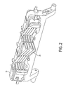
- FIG. 2 shows a front view of a printhead reservoir.
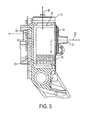
- FIG. 3 shows a cross-sectional view of a comparative example of a printhead reservoir.
- FIG. 4 shows a cross-sectional view of an example of a printhead reservoir according to the invention.
- Figure 1 shows a back view of a printhead reservoir.
- a printhead reservoir contains the ink that the ink jets will eventually spray onto a printing substrate, whether directly, such as onto paper, or indirectly, such as onto a transfer or intermediate surface.
- the printhead reservoir mates with a circuit board or other actuator means that control the operation of the array of jets.
- the circuit board and its coupling to the jets may be referred to as the 'jet stack.'
- the jets draw the ink from a chamber within the reservoir.
- An ink port allows the chamber to be filled with ink.
- the ink port receives pressurized ink through a hose.
- a filter generally prevents particulates from getting into the ink and causing problems with the jetting process. Particulates may clog the jets, causing them to fail or fire off axis.
- the printhead reservoir of Figure 1 has moved the filter out of the jet fluid path, while still keeping the filter in the ink path to regulate particulates in the ink.
- the reservoir 10 has input ink ports such as 12, which couple to a filter 14.
- the filter 14 filters the ink entering the port prior to reaching the chamber 16.
- the back plate of the reservoir may have molded or otherwise formed recesses or cavities to accommodate the filters. With or without the cavities, the back plate may also be referred to as the filter plate.
- the reservoir may comprise a filter plate, a front reservoir and an outlet plate.
- the 'front' reservoir is the reservoir that actually feeds the jets, contrasted with the back reservoir from where the pressurized ink is delivered.
- the chamber 16 is vented to the surrounding atmosphere through a vent hole 18. This alleviates the issues with pressure drop across the filter, as the chamber can regulate its own pressure.
- the vent hole 18 will generally also have an air filter to prevent particulates from contaminating the ink in the chamber 16.
- FIG. 2 shows a front face or outlet plate of the reservoir 10.
- the outlet plate may have several channels such as 20 to direct the ink from the chamber to the jets.
- the circuit board comprising the jet stack would couple to the outlet plate to control the operation of the jets.
- Figure 3 shows a side or cross-sectional view of a comparative example of a reservoir.
- the reservoir 10 has two fluid paths in this example.
- the first fluid path comprises the input fluid path 22 where the ink enters through the ink port 12 and collects in the chamber 16.
- the chamber 16 has vent hole 18, which comprises the air flow path 26.
- the second fluid path is the jet fluid path 24.
- the ink travels along the jet fluid path from the chamber 16 through the channel 20 to the outlet to the jet 28.
- the filter has moved from the jet fluid path, where it causes the problems with excessive pressure drop mentioned above, to the input fluid path. This move allows the jets to pull ink without having the issues with pressure drop.
- the air flow path 26 also contributes to the alleviation of this problem, allowing the chamber to self-regulate the pressure.
- the filter placement in this particular embodiment is outside the vented chamber.
- the placement of the filter 14 with regard to any particular component is optional. However, implementation of the embodiments of the invention should place the filter 'upstream' of a vented chamber between the filtered ink and the jets. In the embodiment of Figure 3 , the filter 14 is outside the vented chamber prior to the input ink port.
- FIG 4 shows an alternative placement of the filter 14, inside the reservoir, but prior to the vented chamber according to an example of the invention.
- the ink enters the reservoir through the ink port 12.
- the filter 14 is actually internal to the reservoir, between the ink port and the vented chamber 16, still residing in the input fluid path.
- the ink may fill the 'intermediate' chamber 30, passing through the filter 14, and spill over into the vented chamber 16.
- the vent hole 18 allows the chamber 16 to self-regulate its pressure. The jets can then draw the ink through the channel 20 without experiencing the pressure drop.
- the filter placement should be in the input fluid path, with a vented chamber lying between the input ink and the jets. This allows the jets to pull ink from a self regulated pressure chamber, and still allows the filter to filter the ink.
- the filter comprises a disc filter made up of a disc of stainless steel felt and a disc of stainless steel mesh both bonded to a formed plate, referred to as the filter plate.
- the filter discs and material mentioned above is an example, but it could be made from alternate materials or shapes. While expensive, the embodiments here use far less of the filter material in four small discs than embodiments using one large piece of filter material for each reservoir. Any materials may be used for the support structure, in this instance the aluminum filter plate. The use of aluminum may have advantages if the rest of the reservoir is constructed out of aluminum as they have the same mechanical properties.
- the reservoir of Figure 1 has four input ports, one each for the colors cyan, magenta, yellow and black. This example implies no limitation and none should be inferred.
- the use of a filter in the fluid path has no limitations as to the number of colors of ink, the types of ink or the size of the reservoir.
Landscapes
- Ink Jet (AREA)
- Particle Formation And Scattering Control In Inkjet Printers (AREA)
Description
- Solid ink printheads generally include an ink reservoir for molten ink, and the reservoir generally has a port between an ink storage chamber and an ink source, and channels leading to an array of jets or openings through which ink is dispensed. The printhead typically dispenses ink onto a printing substrate, such as paper, or an intermediate transfer surface such as a drum or belt. Most, if not all, solid ink reservoirs include a filter in the fluid path between the ink source and the jets to prevent particles from clogging up the jets.
- In some approaches, the filter was in the jet fluid path, which is the fluid path between the chamber and the jets. A problem with this approach arises when the jets pull fluid and there is a pressure drop beyond a certain point. The filter resistance in the fluid jet path may cause the jets to pull a vacuum large enough to cause the jets to fail.
- To overcome the filter resistance in the fluid path, one approach increases the size of the filter. However, the filter material may be expensive, increasing the cost of the printhead and the print system. As print system speeds increase, the jet fluid flow must also increase, requiring a larger filter. In addition, users desire smaller printers, and therefore smaller printheads. A smaller printhead having less filter surface area is counter to faster jetting speeds. Some examples of known printheads are illustrated in
US 5409138 ,EP-A-1403063 andUS-B-6199980 . A problem with these arrangements is the limitation on the size of the filter which can be used. In accordance with the present invention, a reservoir comprises: - an input ink port;
- a vented chamber to receive ink from an ink source through the input ink port; and
- a filter in a path between the input port and the chamber,
- and is characterized in that the input port opens into an intermediate chamber of the reservoir, the filter being located in the intermediate chamber, the intermediate chamber being connected to the vented chamber by an opening in a wall between the two chambers.
- One embodiment comprises a printhead reservoir. The reservoir has an input ink port and a chamber to receive ink from an ink source through the input ink port. The reservoir also has a filter in a path between the input ink port and the chamber.
- Another embodiment comprises a printhead. The printhead includes a reservoir having an input ink port, a chamber to receive ink from an ink source through the input port and a filter in a path between the input port and the storage chamber. The printhead also includes an array of jets to draw ink from the chamber and control circuitry to control the jets so as to selectively output ink through the jets onto a substrate.
- Another embodiment comprises a reservoir having a filter to receive ink, a vented chamber to collect ink received through the filter and at least one jet to receive ink from the vented chamber.
- An example of a printhead reservoir according to the invention will now be described and contrasted with a comparative example with reference to the accompanying drawings, in which:-
-
FIG. 1 shows a back view of a printhead reservoir. -
FIG. 2 shows a front view of a printhead reservoir. -
FIG. 3 shows a cross-sectional view of a comparative example of a printhead reservoir. -
FIG. 4 shows a cross-sectional view of an example of a printhead reservoir according to the invention. -
Figure 1 shows a back view of a printhead reservoir. A printhead reservoir contains the ink that the ink jets will eventually spray onto a printing substrate, whether directly, such as onto paper, or indirectly, such as onto a transfer or intermediate surface. The printhead reservoir mates with a circuit board or other actuator means that control the operation of the array of jets. The circuit board and its coupling to the jets may be referred to as the 'jet stack.' - The jets draw the ink from a chamber within the reservoir. An ink port allows the chamber to be filled with ink. In some instances, the ink port receives pressurized ink through a hose. A filter generally prevents particulates from getting into the ink and causing problems with the jetting process. Particulates may clog the jets, causing them to fail or fire off axis.
- Current implementations of the filter place the filter in the jet fluid path, the path from the chamber to the jets. This may cause a pressure drop across the filter such that the jets 'pull a vacuum' in turn causing the jet or jets to fail. The jets have to pull the ink through the filter in these implementations. One solution to overcome this increases the size of the filter, but that increases the cost because the filter material is expensive, and increases the size of the reservoir to accommodate the increased surface area of the filter necessary to avoid the pressure drop.
- The printhead reservoir of
Figure 1 has moved the filter out of the jet fluid path, while still keeping the filter in the ink path to regulate particulates in the ink. Thereservoir 10 has input ink ports such as 12, which couple to afilter 14. Thefilter 14 filters the ink entering the port prior to reaching thechamber 16. The back plate of the reservoir may have molded or otherwise formed recesses or cavities to accommodate the filters. With or without the cavities, the back plate may also be referred to as the filter plate. The reservoir may comprise a filter plate, a front reservoir and an outlet plate. The 'front' reservoir is the reservoir that actually feeds the jets, contrasted with the back reservoir from where the pressurized ink is delivered. - The
chamber 16 is vented to the surrounding atmosphere through avent hole 18. This alleviates the issues with pressure drop across the filter, as the chamber can regulate its own pressure. Thevent hole 18 will generally also have an air filter to prevent particulates from contaminating the ink in thechamber 16. -
Figure 2 shows a front face or outlet plate of thereservoir 10. The outlet plate may have several channels such as 20 to direct the ink from the chamber to the jets. The circuit board comprising the jet stack would couple to the outlet plate to control the operation of the jets. -
Figure 3 shows a side or cross-sectional view of a comparative example of a reservoir. Thereservoir 10 has two fluid paths in this example. The first fluid path comprises theinput fluid path 22 where the ink enters through theink port 12 and collects in thechamber 16. Thechamber 16 hasvent hole 18, which comprises theair flow path 26. - The second fluid path is the
jet fluid path 24. The ink travels along the jet fluid path from thechamber 16 through thechannel 20 to the outlet to thejet 28. The filter has moved from the jet fluid path, where it causes the problems with excessive pressure drop mentioned above, to the input fluid path. This move allows the jets to pull ink without having the issues with pressure drop. Theair flow path 26 also contributes to the alleviation of this problem, allowing the chamber to self-regulate the pressure. - It must be noted that the filter placement in this particular embodiment is outside the vented chamber. The placement of the
filter 14 with regard to any particular component is optional. However, implementation of the embodiments of the invention should place the filter 'upstream' of a vented chamber between the filtered ink and the jets. In the embodiment ofFigure 3 , thefilter 14 is outside the vented chamber prior to the input ink port. -
Figure 4 shows an alternative placement of thefilter 14, inside the reservoir, but prior to the vented chamber according to an example of the invention.. The ink enters the reservoir through theink port 12. Thefilter 14 is actually internal to the reservoir, between the ink port and the ventedchamber 16, still residing in the input fluid path. The ink may fill the 'intermediate'chamber 30, passing through thefilter 14, and spill over into the ventedchamber 16. Thevent hole 18 allows thechamber 16 to self-regulate its pressure. The jets can then draw the ink through thechannel 20 without experiencing the pressure drop. - As mentioned above, particular embodiments of the reservoir do not limit application of the invention. The filter placement should be in the input fluid path, with a vented chamber lying between the input ink and the jets. This allows the jets to pull ink from a self regulated pressure chamber, and still allows the filter to filter the ink.
- Returning to
Figure 1 , a particular embodiment of afilter 14 is shown. InFigure 1 , the filter comprises a disc filter made up of a disc of stainless steel felt and a disc of stainless steel mesh both bonded to a formed plate, referred to as the filter plate. The filter discs and material mentioned above is an example, but it could be made from alternate materials or shapes. While expensive, the embodiments here use far less of the filter material in four small discs than embodiments using one large piece of filter material for each reservoir. Any materials may be used for the support structure, in this instance the aluminum filter plate. The use of aluminum may have advantages if the rest of the reservoir is constructed out of aluminum as they have the same mechanical properties. - Similarly, it should be noted that the reservoir of
Figure 1 has four input ports, one each for the colors cyan, magenta, yellow and black. This example implies no limitation and none should be inferred. The use of a filter in the fluid path has no limitations as to the number of colors of ink, the types of ink or the size of the reservoir.
Claims (7)
- A reservoir, comprising:an input ink port (12);a vented chamber (16) to receive ink from an ink source through the input ink port; anda filter (14) in a path between the input port and the chamber,characterized in that the input port opens into an intermediate chamber (30) of the reservoir, the filter (14) being located in the intermediate chamber (30), the intermediate chamber (30) being connected to the vented chamber (16) by an opening in a wall between the two chambers.
- The reservoir of claim 1, comprising at least one jet (28) to draw ink from the chamber (16) and along a jet fluid path (24) between the chamber and the jet.
- The reservoir of claim 1 or claim 2, comprising an input storage path between the chamber and the input port.
- The reservoir of any of the preceding claims, wherein the filter (14) comprises a disc filter.
- The reservoir of claim 4, the disc filter (14) comprising a stainless steel felt disc and mesh disc bonded together to a filter plate.
- The reservoir of any of the preceding claims, the reservoir comprising a filter plate, a front reservoir and an outlet plate, the filter plate comprising a filter plate with at least one cavity to accommodate the filter.
- The reservoir of any of the preceding claims, the reservoir comprising one or more vents (18) between the reservoir and a surrounding atmosphere.
Applications Claiming Priority (1)
| Application Number | Priority Date | Filing Date | Title |
|---|---|---|---|
| US11/563,294 US7748830B2 (en) | 2006-11-27 | 2006-11-27 | Printhead reservoir with filter external to jet fluid path |
Publications (3)
| Publication Number | Publication Date |
|---|---|
| EP1925453A2 EP1925453A2 (en) | 2008-05-28 |
| EP1925453A3 EP1925453A3 (en) | 2009-01-07 |
| EP1925453B1 true EP1925453B1 (en) | 2013-08-21 |
Family
ID=39154098
Family Applications (1)
| Application Number | Title | Priority Date | Filing Date |
|---|---|---|---|
| EP07121067.8A Expired - Fee Related EP1925453B1 (en) | 2006-11-27 | 2007-11-20 | Printhead reservoir |
Country Status (4)
| Country | Link |
|---|---|
| US (1) | US7748830B2 (en) |
| EP (1) | EP1925453B1 (en) |
| JP (2) | JP2008132782A (en) |
| BR (1) | BRPI0704248A (en) |
Families Citing this family (11)
| Publication number | Priority date | Publication date | Assignee | Title |
|---|---|---|---|---|
| WO2005108094A1 (en) * | 2004-04-30 | 2005-11-17 | Dimatix, Inc. | Droplet ejection apparatus alignment |
| US7837297B2 (en) | 2006-03-03 | 2010-11-23 | Silverbrook Research Pty Ltd | Printhead with non-priming cavities for pulse damping |
| US7758177B2 (en) * | 2007-03-21 | 2010-07-20 | Silverbrook Research Pty Ltd | High flowrate filter for inkjet printhead |
| US7654640B2 (en) * | 2007-03-21 | 2010-02-02 | Silverbrook Research Pty Ltd | Printhead with drive circuitry components adjacent the printhead IC |
| US8079691B2 (en) * | 2009-02-09 | 2011-12-20 | Xerox Corporation | Foam plate for reducing foam in a printhead |
| USD652446S1 (en) * | 2009-07-02 | 2012-01-17 | Fujifilm Dimatix, Inc. | Printhead assembly |
| US8517508B2 (en) * | 2009-07-02 | 2013-08-27 | Fujifilm Dimatix, Inc. | Positioning jetting assemblies |
| USD653284S1 (en) * | 2009-07-02 | 2012-01-31 | Fujifilm Dimatix, Inc. | Printhead frame |
| US8201928B2 (en) | 2009-12-15 | 2012-06-19 | Xerox Corporation | Inkjet ejector having an improved filter |
| US8403457B2 (en) * | 2011-02-04 | 2013-03-26 | Xerox Corporation | Waste ink reclamation apparatus for liquid ink recirculation system |
| US8864293B2 (en) * | 2012-09-12 | 2014-10-21 | Xerox Corporation | Phase change ink reservoir for a phase change inkjet printer |
Family Cites Families (22)
| Publication number | Priority date | Publication date | Assignee | Title |
|---|---|---|---|---|
| JPS5615364A (en) * | 1979-07-18 | 1981-02-14 | Toshiba Corp | Ink jet recorder |
| JP2718724B2 (en) * | 1987-11-27 | 1998-02-25 | キヤノン株式会社 | Ink jet recording apparatus, cap unit for the apparatus, and method of recovering ink jet head |
| JPH01228860A (en) * | 1988-03-09 | 1989-09-12 | Canon Inc | Ink jet recording head |
| JPH0699589A (en) * | 1992-09-22 | 1994-04-12 | Brother Ind Ltd | Liquid supply device |
| JPH0717050A (en) * | 1993-07-02 | 1995-01-20 | Brother Ind Ltd | Filter device in ink jet printer |
| EP0683050B1 (en) * | 1994-05-20 | 2000-08-02 | Canon Kabushiki Kaisha | Ink supplying apparatus and ink jet recording apparatus having same |
| US6217164B1 (en) * | 1997-12-09 | 2001-04-17 | Brother Kogyo Kabushiki Kaisha | Ink jet recorder |
| NL1008040C2 (en) * | 1998-01-16 | 1999-07-19 | Oce Tech Bv | Ink supply holder suitable for connection to an inkjet printhead as well as a system of such an ink supply holder and an inkjet printhead. |
| US6398354B1 (en) * | 1999-06-30 | 2002-06-04 | Lexmark International, Inc. | Printhead apparatus and printer having separate filtration device and method for attaching said device |
| US6199980B1 (en) * | 1999-11-01 | 2001-03-13 | Xerox Corporation | Efficient fluid filtering device and an ink jet printhead including the same |
| JP3726659B2 (en) * | 2000-08-30 | 2005-12-14 | ブラザー工業株式会社 | Inkjet recording device |
| IL150369A0 (en) * | 2000-10-23 | 2002-12-01 | Aprion Digital Ltd | A closed ink delivery system with print head ink pressure control and method of same |
| JP2002144576A (en) * | 2000-11-17 | 2002-05-21 | Canon Inc | Liquid jet head and liquid jet device |
| US7044591B2 (en) | 2002-09-25 | 2006-05-16 | Brother Kogya Kabushiki Kaisha | Ink-jet head, filter assembly used for manufacturing the ink-jet head, and method for manufacturing the ink-jet head using the filter assembly |
| JP2004122500A (en) * | 2002-09-30 | 2004-04-22 | Canon Inc | Liquid communication structure for interconnecting liquid containing section and liquid using section, and liquid supply system and ink jet recorder employing the liquid communication structure |
| US7121658B2 (en) * | 2004-01-07 | 2006-10-17 | Xerox Corporation | Print head reservoir having purge vents |
| JP2005279962A (en) * | 2004-03-26 | 2005-10-13 | Canon Inc | Fluid communication structure, ink jet recording head and recorder employing that structure |
| JP2005335349A (en) * | 2004-05-31 | 2005-12-08 | Canon Inc | Inkjet head and its manufacturing method |
| JP2006001200A (en) * | 2004-06-18 | 2006-01-05 | Seiko Epson Corp | Gas exhausting structure of liquid holding chamber and liquid jetting apparatus equipped with the liquid holding chamber |
| JP4561276B2 (en) * | 2004-09-22 | 2010-10-13 | 富士ゼロックス株式会社 | Inkjet recording device |
| JP2006188047A (en) * | 2004-12-06 | 2006-07-20 | Konica Minolta Holdings Inc | Method of manufacturing inkjet head |
| JP4910368B2 (en) * | 2005-11-15 | 2012-04-04 | 富士ゼロックス株式会社 | Filter device and droplet discharge device |
-
2006
- 2006-11-27 US US11/563,294 patent/US7748830B2/en not_active Expired - Fee Related
-
2007
- 2007-11-20 EP EP07121067.8A patent/EP1925453B1/en not_active Expired - Fee Related
- 2007-11-21 JP JP2007301470A patent/JP2008132782A/en active Pending
- 2007-11-27 BR BRPI0704248-5A patent/BRPI0704248A/en not_active IP Right Cessation
-
2013
- 2013-09-09 JP JP2013185909A patent/JP5726969B2/en not_active Expired - Fee Related
Also Published As
| Publication number | Publication date |
|---|---|
| US7748830B2 (en) | 2010-07-06 |
| BRPI0704248A (en) | 2008-07-15 |
| EP1925453A2 (en) | 2008-05-28 |
| US20080122912A1 (en) | 2008-05-29 |
| JP5726969B2 (en) | 2015-06-03 |
| EP1925453A3 (en) | 2009-01-07 |
| JP2013241024A (en) | 2013-12-05 |
| JP2008132782A (en) | 2008-06-12 |
Similar Documents
| Publication | Publication Date | Title |
|---|---|---|
| EP1925453B1 (en) | Printhead reservoir | |
| US9630408B2 (en) | Inkjet head that circulates ink | |
| US8684507B2 (en) | Liquid ejecting head, liquid ejecting unit, and liquid ejecting apparatus | |
| EP1368198B1 (en) | Inkjet printing system using filter for pigmented inks | |
| US20020180827A1 (en) | Ink jet head | |
| US9694582B1 (en) | Single jet recirculation in an inkjet print head | |
| JP2008137385A (en) | Printhead reservoir with filter used as check valve | |
| US20080129808A1 (en) | Printhead reservoir with siphon vents | |
| EP2043869B1 (en) | Print cartridge | |
| JPS61130054A (en) | Ink jet printer | |
| EP2360019B1 (en) | Liquid ejecting head | |
| JP2005074836A (en) | Inkjet head unit | |
| US7144100B2 (en) | Purgeable print head reservoir | |
| JP2007182076A (en) | External manifold of inkjet nozzle stack | |
| US6827422B2 (en) | Liquid suction apparatus for liquid ejecting head and liquid ejecting apparatus | |
| US10668725B2 (en) | Supply manifold in a printhead | |
| EP3536508B1 (en) | Printhead | |
| US10391781B1 (en) | Printhead that evacuates air from a supply manifold | |
| JP5246599B2 (en) | Image forming apparatus | |
| KR20150064665A (en) | Single jet fluidic design for high packing density in inkjet print heads | |
| US20090179977A1 (en) | Compact ink filter assembly | |
| JP5950081B2 (en) | Liquid ejecting head and liquid ejecting apparatus | |
| JP3125718B2 (en) | Liquid supply device and recording device | |
| EP3356148B1 (en) | Printheads | |
| JP4917703B2 (en) | Inkjet printer head |
Legal Events
| Date | Code | Title | Description |
|---|---|---|---|
| PUAI | Public reference made under article 153(3) epc to a published international application that has entered the european phase |
Free format text: ORIGINAL CODE: 0009012 |
|
| AK | Designated contracting states |
Kind code of ref document: A2 Designated state(s): AT BE BG CH CY CZ DE DK EE ES FI FR GB GR HU IE IS IT LI LT LU LV MC MT NL PL PT RO SE SI SK TR |
|
| AX | Request for extension of the european patent |
Extension state: AL BA HR MK RS |
|
| PUAL | Search report despatched |
Free format text: ORIGINAL CODE: 0009013 |
|
| AK | Designated contracting states |
Kind code of ref document: A3 Designated state(s): AT BE BG CH CY CZ DE DK EE ES FI FR GB GR HU IE IS IT LI LT LU LV MC MT NL PL PT RO SE SI SK TR |
|
| AX | Request for extension of the european patent |
Extension state: AL BA HR MK RS |
|
| 17P | Request for examination filed |
Effective date: 20090707 |
|
| 17Q | First examination report despatched |
Effective date: 20090731 |
|
| AKX | Designation fees paid |
Designated state(s): DE FR GB |
|
| GRAJ | Information related to disapproval of communication of intention to grant by the applicant or resumption of examination proceedings by the epo deleted |
Free format text: ORIGINAL CODE: EPIDOSDIGR1 |
|
| GRAP | Despatch of communication of intention to grant a patent |
Free format text: ORIGINAL CODE: EPIDOSNIGR1 |
|
| INTG | Intention to grant announced |
Effective date: 20130513 |
|
| GRAS | Grant fee paid |
Free format text: ORIGINAL CODE: EPIDOSNIGR3 |
|
| GRAA | (expected) grant |
Free format text: ORIGINAL CODE: 0009210 |
|
| AK | Designated contracting states |
Kind code of ref document: B1 Designated state(s): DE FR GB |
|
| REG | Reference to a national code |
Ref country code: GB Ref legal event code: FG4D |
|
| REG | Reference to a national code |
Ref country code: DE Ref legal event code: R096 Ref document number: 602007032345 Country of ref document: DE Effective date: 20131017 |
|
| PLBE | No opposition filed within time limit |
Free format text: ORIGINAL CODE: 0009261 |
|
| STAA | Information on the status of an ep patent application or granted ep patent |
Free format text: STATUS: NO OPPOSITION FILED WITHIN TIME LIMIT |
|
| 26N | No opposition filed |
Effective date: 20140522 |
|
| REG | Reference to a national code |
Ref country code: DE Ref legal event code: R097 Ref document number: 602007032345 Country of ref document: DE Effective date: 20140522 |
|
| REG | Reference to a national code |
Ref country code: FR Ref legal event code: PLFP Year of fee payment: 9 |
|
| REG | Reference to a national code |
Ref country code: FR Ref legal event code: PLFP Year of fee payment: 10 |
|
| REG | Reference to a national code |
Ref country code: FR Ref legal event code: PLFP Year of fee payment: 11 |
|
| PGFP | Annual fee paid to national office [announced via postgrant information from national office to epo] |
Ref country code: DE Payment date: 20171019 Year of fee payment: 11 Ref country code: FR Payment date: 20171020 Year of fee payment: 11 |
|
| PGFP | Annual fee paid to national office [announced via postgrant information from national office to epo] |
Ref country code: GB Payment date: 20171020 Year of fee payment: 11 |
|
| REG | Reference to a national code |
Ref country code: DE Ref legal event code: R119 Ref document number: 602007032345 Country of ref document: DE |
|
| GBPC | Gb: european patent ceased through non-payment of renewal fee |
Effective date: 20181120 |
|
| PG25 | Lapsed in a contracting state [announced via postgrant information from national office to epo] |
Ref country code: FR Free format text: LAPSE BECAUSE OF NON-PAYMENT OF DUE FEES Effective date: 20181130 Ref country code: DE Free format text: LAPSE BECAUSE OF NON-PAYMENT OF DUE FEES Effective date: 20190601 |
|
| PG25 | Lapsed in a contracting state [announced via postgrant information from national office to epo] |
Ref country code: GB Free format text: LAPSE BECAUSE OF NON-PAYMENT OF DUE FEES Effective date: 20181120 |