JP2004122500A - Liquid communication structure for interconnecting liquid containing section and liquid using section, and liquid supply system and ink jet recorder employing the liquid communication structure - Google Patents
Liquid communication structure for interconnecting liquid containing section and liquid using section, and liquid supply system and ink jet recorder employing the liquid communication structure Download PDFInfo
- Publication number
- JP2004122500A JP2004122500A JP2002287837A JP2002287837A JP2004122500A JP 2004122500 A JP2004122500 A JP 2004122500A JP 2002287837 A JP2002287837 A JP 2002287837A JP 2002287837 A JP2002287837 A JP 2002287837A JP 2004122500 A JP2004122500 A JP 2004122500A
- Authority
- JP
- Japan
- Prior art keywords
- liquid
- ink
- gas
- supply system
- communication
- Prior art date
- Legal status (The legal status is an assumption and is not a legal conclusion. Google has not performed a legal analysis and makes no representation as to the accuracy of the status listed.)
- Pending
Links
Images


Landscapes
- Ink Jet (AREA)
Abstract
Description
【0001】
【発明の属する技術分野】
本発明は、例えば、液体使用部としての記録ヘッドあるいはペンなどに、インクなどの液体を、液体収納部としてのインクタンクなどから無駄なくかつ安定して供給するとともに、液体使用部内に存在する気体を液体収納部へ排出するための液体連通構造、およびこれを用いた液体供給システムおよび該システムを用いるインクジェット記録装置に関するものである。
【0002】
【従来の技術】
液体使用装置、例えばインクジェット記録ヘッドを用いて記録媒体へと液体であるインクを付与することにより記録媒体上に画像を形成するインクジェット記録装置は、記録時の騒音が比較的小さくしかも小さなドットを高い密度で形成できるため、昨今においてはカラー印刷を含めた多くの印刷に利用されている。このようなインクジェット記録装置の一形態として、一体不可分にまたは分離可能に取り付けられたインクタンクからインクの供給を受けるインクジェット記録ヘッドと、記録ヘッドを搭載して記録媒体に対し記録ヘッドを所定方向に相対的に走査させるキャリッジと、記録媒体を記録ヘッドに対して上記所定方向に直交する方向に相対的に搬送(副走査)させる搬送手段と、を具え、記録ヘッドの主走査の過程でインク吐出を行わせることにより記録を行うものがある。さらに、キャリッジ上に、ブラックインクおよびイエロー、シアン、マゼンタ等の各カラーインクが吐出が可能な記録ヘッドを搭載し、ブラックインクによるテキスト画像のモノクローム印刷のみではなく、各インクの吐出割合を変えることにより、フルカラー印刷を可能としたものもある。
【0003】
かかるインクジェット記録装置においては、インク供給経路内部に混入してくる、またはしている空気等の気体の排出を適切に行うことが問題となる。
【0004】
ここで、供給系内部に進入してくる気体には大きく分類して4種類の発生要因がある。
1)プリントヘッドのインク吐出口から進入する、ないしは吐出動作に伴って発生するもの、
2)インク内部に溶存していた気体が分離したもの、
3)供給経路を構成する素材を通して外部から気体透過により進入してくるもの、および、
4)カートリッジ形態のインクタンクを交換する際に進入してくるもの、
である。
【0005】
ところで、インクジェット記録ヘッド内に形成されるインク流路は非常に微細に構成されており、従ってインクタンクから記録ヘッドに供給されるインクは、塵埃等の異物が混入していない清浄な状態であることが要求される。すなわち、塵埃等の異物が混入しているような場合、記録ヘッド内のインク流路の中でも特に狭い吐出口ないしこれに直接連通する液路部分に異物が詰まるという問題が発生し、これにより正常なインクの吐出動作が行えなくなり、記録ヘッドの機能の回復が不可能となることもある。
【0006】
そこで、一般に記録ヘッドと、インクタンクに突入するインク供給針との間のインク流路に、異物を除去するフィルタ部材を配置し、このフィルタ部材によって記録ヘッド側への異物の侵入が防止できるように構成されることが多い。
【0007】
一方、昨今においては記録の高速化を実現するために、インクを吐出するための吐出口数も増してきており、またインクを吐出させるためのエネルギを発生する素子に加える駆動信号も益々高周波数のものが採用されつつある。このために、単位時間当たりのインクの消費量も急激に増加している。
【0008】
これに伴い、フィルタ部材を通過するインク量も当然ながら増大するが、フィルタ部材による圧力損失を低減するためには、供給路を一部拡大して大面積のフィルタ部材を配置するのが有効である。このために、供給経路内に気泡が混入すると、拡大部におけるフィルタ部材の上流側の空間に滞留し易く、これを排出できない状態となって、インクの円滑な供給が阻害されるという問題が生じる。また、供給経路内部に溜まっていた気体が微細な気泡となって吐出口に導かれるインク内部に混入し、インクの不吐出を生じさせる等の問題を引き起こす恐れもある。
【0009】
従って、インク供給経路内に滞留する空気は速やかに除去されることが強く望ましく、そのためにいくつかの方法が挙げられる。
【0010】
その一つは、次に述べるようなクリーニング操作を行うことである。
インクジェット記録ヘッドは、記録媒体に対向して配置される吐出口から液体であるインクを例えば滴として吐出させて印刷を行う関係上、吐出口からのインク溶媒の蒸発に起因するインク粘度の上昇やインクの固化、吐出口への塵埃の付着、さらには吐出口内方の液路への気泡の混入などにより吐出口に目詰まり等が生じ、印刷不良を起こすことがある。
【0011】
このために、インクジェット記録装置には、非印刷動作時に記録ヘッドの吐出口を覆うためのキャッピング手段や、吐出口が形成された記録ヘッドの面(吐出口形成面)を必要に応じて清掃するワイピング部材が備えられる。キャッピング手段は、印刷の休止時に前述した吐出口のインクの乾燥を防止する蓋として機能するだけでなく、吐出口に目詰まりが生じた場合には、キャップ部材により吐出口形成面を覆い、例えばキャップ部材の内部に連通する吸引ポンプにより負圧を作用させることにより、吐出口からインクを吸引排出させて吐出口のインク固化による目詰まりや、液路内の増粘インクあるいは混入気泡によるインク吐出不良を解消する機能をも備えている。
【0012】
これらインク吐出不良を解消させるために行うインクの強制的な排出処理はクリーニング操作とも呼ばれ、これは装置の長時間の休止後に印刷を再開する場合や、またユーザが記録画像の品質が悪化したのを認識して例えばクリーニングスイッチを操作した場合などに実行され、そのようにインクを強制排出させた後に、ゴムなどの弾性板からなるワイピング部材により吐出口形成面のワイピング操作を伴う処理である。
【0013】
そして、インクを初めて記録ヘッドの流路ないし液路内へ充填するための初期充填時や、インクタンクを交換した場合に実行されるクリーニング操作時において、キャッピングされた吐出口形成面に対し吸引ポンプを高速度で駆動することで大きな負圧を作用せしめ、これによりインク供給路内で高い流速を得て滞留気泡を排出させようとする試みもなされている。
【0014】
しかしながら、フィルタ部材が持つ動圧を抑えるためのフィルタ部材の面積の増大化と、残留気泡との問題は相容れない作用に基づくものであり、残留気泡を吐出口側から吸引ポンプで除去するのは極めて困難である。すなわち、吸引ポンプによるインクの流れにより気泡がフィルタを通過する条件として、フィルタを通過するインクに所定の流速が必要であるが、それを発生させるにはフィルタ両側に大きな圧力差を生じさせなくてはならない。それを実現するには、通常フィルタ面積を小さくして流路抵抗を高めるか、吸引ポンプを大流量化することが考えられるが、フィルタを小さくするとヘッドへの供給性能が損なわれ、また、大流量で気体を除去しようとする場合には、大量のインクが排出されてしまい、インクをいたずらに消費することにもなる。
【0015】
そこで、気泡除去の他の方法として考えられるのは、外部へ直接排出させる方法と、インクタンク側に移動させ、インク供給を阻害しないタンク内の部位に留めてしまう方法との二つとなる。これらのうち、前者については、供給路中に外部への連通口を配置する構成を有するものとなるが、これは次の理由により好ましい方法とは言えない。
【0016】
すなわち、通常のインクジェット記録装置においては、吐出口からのインクの好ましくない漏出を防止する目的で、インクタンク内に吸収体などの毛管力発生部材を配設したり、あるいは可撓性のインク収納袋に対しばね等の弾性部材を配置して内容積拡大方向への付勢力を作用させたりすることにより、インクタンクのインク収納空間に負圧を発生させているものが多い。このような場合においては、供給路に気泡除去のために単なる連通口が配置されると、却って連通口からエアが侵入することで負圧が解除されてしまうことになるので、連通口には圧力調整弁等の配設が必要となり、インク供給システムひいてはこれを用いる記録装置の構造が複雑化・大型化することになるからである。また、気泡排出用の連通口からのインクの漏洩を防止するために、気体は通過できるが液体は通過できない撥水膜等の配設を要したり、あるいは気泡が滞留した場合にのみ連通口を開放して排出させる装置(気泡量検知機構や連通口開閉機構等)が必要となるので、製造価格の増大や構造の複雑化・大型化が生じるからである。
【0017】
一方、インクタンク側に気泡を移動させることを考える。このとき、インクタンクに移動する気泡の体積に相当する量のインクをヘッド側に移送することができれば、インクタンク内容積の変動はなく、発生する負圧を一定として、記録ヘッドに対し吐出口に形成されるメニスカスの保持力と平衡する負圧を作用することができるので、好ましいことである。また、インクタンクがカートリッジ形態のものであれば、収納するインク残量がなくなったときに新しいものと交換されるので、インク供給系から完全に気体を除去することができる構成であると言い得る。
【0018】
ここで、インクタンク側に気体を円滑に移送する上で、上記拡大部におけるフィルタ部材の上流側の部分をさらに上流側に向かって例えばテーパ状に形成すること、すなわちインク供給針からのインク供給路がフィルタ部材配設位置に向かって急拡大しないように形成することが有効であるとも考えられる。
【0019】
しかし、民生用に広く普及しているインクジェット記録装置においては、ブラックインクおよびカラーインクをそれぞれ収納したカートリッジ形態のインクタンクを、記録ヘッドないしこれを搭載するキャリッジに対しその上部から着脱可能に装着できるように構成されることが多く、例えばインクカートリッジにはキャリッジに上向きに搭載された中空のインク供給針を突入させて記録ヘッドに対するインク供給が可能となるように構成されている。従って、インクカートリッジと記録ヘッドを連結するインク供給針の管径が問題となる。つまり、カートリッジ装着の操作を簡便にするためにも、細い供給針が求められているが、細い管の場合メニスカス力が大きくなるために気泡を円滑に移動することができないのである。
【0020】
ところで、インクタンク側に気体を移動させる機構については、これまでにもいくつかの提案がなされている。
【0021】
例えば、特許文献1においては、記録ヘッド側を、大気連通口を有する第1室と毛管力発生部材を有する第2室とに分離し、第1室とインクタンクとを第1室側の開口の高さが異なる2以上の連通路で連結させることで、連通路の1つからインクタンク側にエアが供給されるようにした構成が開示されている。かかる構成は、第1室と第2室との水頭差、あるいは、第2室に配置した毛管力発生部材によりヘッドに負圧を作用させているものであり、第1室に大気連通口を配置させることができている。
【0022】
しかしながら、この特許文献1の構成は、変形しないインクタンク内のインクを使い切るためにインク供給に応じて大気を導入することが目的であり、インク供給経路内に残留した気泡の排除を目的とするものではない。特に、インクの供給路となる第1室は大気連通口によって大気開放されているため負圧が発生しない、常時大気に触れているもので、本願のようにヘッドに所定の負圧を印加するためインク収容部やインク供給部を実質的に密閉するシステムとは異なり、密閉供給系特有の気体混入についての課題の認識すらない。すなわち、インク供給経路とりわけ第2室ないし記録ヘッド側からの気体をもインクタンクに移送するために同文献開示の技術を適用することはできない。
【0023】
また、他の提案として、特許文献2には、負圧発生部材収納室と液体収納室とを分離可能とした場合に、両者を連結する連通部に気体優先導入路と液体導出路とを配置し、確実に気体を導入できるようにした構成が開示されている。しかしながら、同文献においても、インクタンクと記録ヘッドとの間に毛管力発生部材と大気連通口が配置されている構成が開示されており、特許文献1と同様、大気連通口としての開口から気体が自由に出入りする大気開放系のインク供給路であり、密閉系特有のインク供給経路内に残留した気泡の排除をするという観点すらなく、同文献開示の技術は適用できない。
【0024】
さらに、特許文献3には、下側に液体導出管(drain conduit 66,72,74)と気体導入管(vent conduit 76,82,84)を突出させてなるインク収納容器(ink container 50)が開示され、液体導出管は収納容器の内壁底面に上部開口があり、気体導出管は収納容器の収納空間内部に開口が配置されている構成が示されている。同文献に開示の技術の目的は、リザーバ(reservoir 16,18,20)を有する部材(14)にインクをリフィルするためのシステムの構成であって、リザーバより下流のインク供給経路ないしインクを使用する部分内に残留している気泡除去を目的としたものではない。また、液体導出管と気体導入管の下部開口高さが等しいために管内でメニスカスを形成してしまうと、液体や気体の移動ができなくなるとも考えられる。さらに、インク収納容器および部材14の内部と大気とを連通する連通口が存在せず、かつ負圧を調整する要素がないため、インクの使用を続けて行くと内部の負圧が急激に高まり、インク使用部分に対するインク供給不能に陥る原理のものである。
【0025】
さらに、特許文献4には、負圧発生部材収納室とインク収納室とを有してなるリザーバタンクにインクを補充するための補充タンクが結合可能で、インク収納室の空間に対しその上部および下部において補充タンクが結合した場合に、下部の液体連通管を介して補充タンクからインクがインク収納室に導入される一方、上部の気体連通管を介してインク収納室から空気が補充タンク側に導入されるようにした構成が開示されている。しかしながら、同文献においても、インク収納室と記録ヘッドとの間に負圧発生部材と大気連通口とが配置されている構成において特許文献1および2と本質的に変わりはなく、従って密閉系特有のインク供給経路内に残留した気泡の排除をするという観点すらなく、同文献開示の技術を適用できすることはできない。
【0026】
【特許文献1】
特開平5−96744号公報
【0027】
【特許文献2】
特開平11−309876号公報
【0028】
【特許文献3】
米国特許第6,347,863号明細書
【0029】
【特許文献4】
特開平10−29318号公報
【0030】
【発明が解決しようとする課題】
以上の通り、これら特許文献1〜4には、気体をインクタンクに導入する点については開示があるが、使用状態において密閉構造であるインク供給経路内に滞留する気体を、インクタンク側に円滑に移送し、留めておく目的には、いずれも合致していない。
【0031】
よって本発明は、液体使用部分に対して密閉構造を持つ液体供給システムにおいて、液体使用動作および液体供給動作の障害となる気体を、構造の複雑化を伴うことなく液体供給経路から迅速かつ円滑に排除できるようにすることを目的とする。
【0032】
また、本発明の他の目的は、密閉構造のインク供給経路内に残留する気体を円滑かつ迅速にインクタンク側に移送させると共に、記録装置の実使用時においても、滞留気泡に起因する問題点、すなわちインク供給の不良や混入気泡による吐出口の目詰まり等に起因した記録不良が生じないインクジェット記録装置を提供することにある。
【0033】
さらに、本発明は、インクタンクへの気体の上記移送性能を活用し、インクタンクの構成の簡略化および低廉化を図ることを目的とする。
【0034】
【課題を解決するための手段】
そのために、本発明液は、液体を収納する液体収納部と、前記液体を使用する液体使用部とを液体連通する液体連通構造であって、前記液体連通構造は、それぞれが前記液体収納部と前記液体使用部とを連通する複数の連通路を具え、前記液体収納部側が前記液体収納部内の前記液体の存在によって閉状態となり、かつ、前記液体使用部側が前記液体使用部内の前記液体の存在によって実質的密閉空間を形成し、前記密閉空間内に気体が存在する状態において、前記気体を、前記複数の連通路の一部を介して、前記液体収納部に移送可能であるとともに、前記密閉空間をなす部位に設けられ、前記液体使用部への前記液体の供給に伴って、液体供給経路内部に外気を導入可能な弁機構を具えたことを特徴とする。
【0035】
ここで、前記複数の連通路の少なくとも一部の前記液体使用部側付近に気体が存在する状態において、前記複数の連通路の一部の連通路を介して前記液体収納部から前記液体使用部に前記液体が移動すると同時に、前記複数の連通路の他の一部の連通路を介して前記気体が前記液体収納部に移送されるものとすることができる。
【0036】
そして、前記複数の連通路の少なくとも一部の前記液体使用部側付近に気体が存在する状態において、前記複数の連通路の一部の連通路を介して前記液体収納部から前記液体使用部に前記液体が移動して前記液体使用部内の前記気体圧力が増加することで、前記複数の連通路の他の一部の連通路の連通路を介して前記気体が前記液体収納部に移送されるものとすることができる。
【0037】
以上にあって、液体使用時の姿勢において、鉛直方向に関し、前記液体連通構造は、前記液体収納部より実質的に下位に位置し、さらに前記液体使用部より実質的に上位に位置するものとすることができる。
【0038】
さらに、本発明は、上記のいずれかの液体連通構造を用い、前記液体収納部から前記液体使用部に前記液体を供給可能な液体供給システムに存する。
【0039】
ここで、前記液体収納部は、液体の収納空間を画成するとともに、前記液体使用部への前記液体の供給に伴って前記収納空間の内容積を減少する方向に変位可能な可動部材を少なくとも一部に有するさらに前記液体収納部は、前記変位の方向とは反対の方向に前記可動部材を付勢する付勢部材を有するものとすることができる。
【0040】
または、前記密閉空間に液体連通した状態で設けられ、液体の収納空間を画成するとともに、前記液体収納部から前記液体使用部へ前記液体供給経路を介した液体の供給に伴って、前記収納空間の容積を減少する方向に変位可能な可動部材を少なくとも一部に有するとともに、当該変位の方向とは反対の方向に前記可動部材を付勢する付勢部材を有するものとすることができる。
【0041】
以上において、前記弁機構は、前記液体供給経路内の負圧が所定値以上に高まったときに前記外気の導入を行うものとすることができる。
【0042】
また、前記液体収納部を前記複数の連通路を介して前記液体供給経路に着脱可能とすることができる。
【0043】
ここで、前記液体収納部の非装着時に、前記複数の連通路の前記液体収納部側の開口を閉塞可能なシャッタ部材を具えることができる。
【0044】
また、以上において、前記液体使用部は前記液体としてのインクを吐出することにより記録を行うためのインクジェット記録ヘッドであり、該インクジェット記録ヘッドに前記インクを導くものとすることができる。
【0045】
ここで、前記記録ヘッドを分離可能に一体に構成されてなるものとすることができる。
【0046】
また、本発明は、それらのような液体供給システムを用い、使用時の姿勢において、鉛直方向に関し、前記液体供給経路より前記複数の連通路が実質的に上位に位置し、さらに前記液体収納部が前記複数の連通路より実質的に上位に位置するよう前記液体供給システムを保持して記録を行うインクジェット記録装置に存する。
【0047】
さらに、本発明は、以上のいずれかの形態の液体供給システムに用いられる前記液体収納部をなし、前記複数の連通路を介して前記液体供給経路に接続可能である液体タンクに存する。
【0048】
また、上記液体供給システムにおいて、前記弁機構は、前記液体供給経路内への前記外気の導入は許可し、反対方向への液体または気体の移動を許可しないものとすることができる。
【0049】
さらに、本発明は、液体としてのインクを吐出することにより記録を行うためのインクジェット記録ヘッドであって、上記いずれかの形態の液体連通構造を一体に有することを特徴とする。
【0050】
ここで、インクジェット記録装置に対し着脱可能なカートリッジの形態を有するものとすることができる。
【0051】
加えて、本発明液体タンクは、上記いずれかの形態の液体連通構造に接続される前記液体収納部をなし、前記複数の連通路を介して前記液体連通構造に接続可能なカートリッジの形態を有することを特徴とする。
【0052】
また、本発明液体タンクは、上記インクジェット記録ヘッドが有する前記液体連通構造に対して、前記複数の連通路を介して接続可能なカートリッジの形態を有することを特徴とする。
【0053】
【発明の実施の形態】
以下に、本発明をインクジェット記録装置に適用したいくつかの実施の形態について図面を参照して説明する。
【0054】
なお、本明細書において、「記録」とは、文字、図形等有意の情報を形成する場合のみならず、有意無意を問わず、また人間が視覚で知覚し得るように顕在化したものであるか否かを問わず、広く記録媒体上に画像、模様、パターン等を形成する場合、または記録媒体の加工を行う場合を言うものとする。
【0055】
また、「記録媒体」とは、一般的な記録装置で用いられる紙のみならず、広く、布、プラスチック・フィルム、金属板等、ガラス、セラミックス、木材、皮革等、インクを受容可能な物も言うものとするが、以下では「用紙」または単に「紙」ともいうものとする。
【0056】
なお、本発明の液体供給システムに用いられる液体として、以下の各実施形態ではインクを例にとって説明を行っているが、適用可能な液体としては、インクに限ることなく、例えばインクジェット記録分野にあっては、記録媒体に対する処理液などを含むことは言うまでもない。
【0057】
(第1の実施形態)
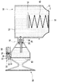
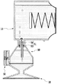
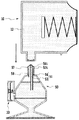
図1は本発明の第1の実施形態による液体供給システムの模式的断面図である。
【0058】
図1に示す実施形態のインク供給システムは概して、液体収納容器としてのインクタンク10と、インクジェット記録ヘッド(以下、単に「記録ヘッド」と称する)20と、それらの間を連絡するインク供給路を形成する供給部50とから構成されている。供給部50は、記録ヘッド20と分離可能または分離不能に一体のものでも良く、また、記録ヘッド20を搭載するキャリッジに設けられてその上部からインクタンク10が着脱可能であるとともに、当該装着時においてインクタンク10から記録ヘッド20に至るインク供給経路を閉成するものでも良い。
【0059】
インクタンク10は、概してインク収納空間が画成されるインク収納室12からなり、インク収納室12内には記録ヘッドから吐出させるためのインクが収納され、吐出動作に伴って記録ヘッドに供給される。
【0060】
インク収納室12には、一部に変形可能な可撓性膜(シート部材)11が配設されており、この部分と不撓性の外装15との間でインクを収納する空間を画成している。このシート部材11から見たインク収納空間に対する外側空間、すなわち図におけるシート部材11に対して上側の空間は、大気に開放され大気圧と等しくされている。さらにこのインク収納空間内は、下方に設けられている供給部材への接続部およびバルブ室への連通路13を除いて、実質的に密閉空間を形成している。
【0061】
本例のシート部材11の中央部分は平板状の支持部材である圧力板14によって形状が規制されており、その周縁部分が変形可能となっている。そして、このシート部材11は、予めその中央部分が凸状に形成されていて、側面形状がほぼ台形となっている。このシート部材11は、後述するように、インク収納空間内におけるインク量の変化や圧力変動に応じて変形する。その際に、シート部材11の周辺部分がバランスよく伸縮変形し、そのシート部材11の中央部分がほぼ水平姿勢を保ったまま、図の左右方向に平行移動する。このようにシート部材11がスムーズに変形(移動)するため、その変形に伴う衝撃の発生がなく、衝撃に起因するインク収納空間内に異常な圧力変動が生じることもない。
【0062】
またインク収納空間内には、圧力板14を介してシート部材11を図の右方向に付勢する押圧力を作用することで、記録ヘッドのインク吐出部に形成されるメニスカスの保持力と平衡して記録ヘッドのインク吐出動作が可能な範囲にある負圧を発生させる圧縮ばね形態のばね部材40が設けられている。それとともに、インク収納室内の空気が環境変化(周囲温度や気圧)によって体積変動した場合、ばねとシートの変位で受容し、室内の負圧が大きく変動しないようになっている。(この表現は、他の件にも反映させてください。この機構はバッファ効果がメインで、ある程度の負圧を発生している程度。タンク内の負圧を制御するのは一方向バルブがメイン。)19はばね部材40を支持する固定部材である。
【0063】
なお、図1の状態は、インク収納空間内にほぼ完全にインクが充填された状態を示しているが、この状態でもばね部材40は圧縮された状態にあり、インク収納空間内に適切な負圧が生じているものとする。
【0064】
記録ヘッド20とインクタンク10との結合は、図示の例では記録ヘッドに一体に設けられている供給部50の接続部51がインクタンク10内に挿入されることによってなされる。これによって両者が流体的に結合され、記録ヘッド20へ向けてインクが供給可能となる。なお、この接続部51が挿通されるインクタンク側開口にはゴム等の封止部材17が取り付けられ、接続部51の周囲に密着してインクタンク10からのインク漏出を防止するとともに、接続部51とインクタンク10との接続を確実なものにしている。なお、封止部材17には、接続部51の挿通を容易とするために、当該挿通位置に予めスリット等を形成しておいてもよい。そして、接続部51が挿通されないときは、封止部材17自体の弾性力によってスリットが閉じられることにより、インクの漏出を防止しているものである。
【0065】
接続部51は内部が軸方向に沿って2分割された中空針状の部材であり、それぞれの中空部の、上側すなわちインク収納室12内に位置づけられる開口位置(以下、タンク側開口位置という)は鉛直方向に関してほぼ同一の高さである一方、下側すなわちヘッドに連結された供給部内での開口位置(以下、ヘッド側開口位置という)は高さが異なる構成となっている。以下、供給部50内でのヘッド側開口位置が鉛直方向において相対的に下にある方の流路(図中の右の流路)をインク流路54、ヘッド側開口位置が鉛直方向において上にある方の流路(図中の左の流路)をエア流路54と称するが、これは気泡排除過程において、主としてインク流路53からインクが記録ヘッド側に導出され、エア流路54からはインクタンク側にエアが移送されるからであって、後述するように各流路においてインクおよびエアの両者の移動も行われるものである。すなわち、それら流路の呼称は、それぞれの流体専用であることを意味するものではない。
【0066】
供給部50内におけるインク供給経路は、インクタンク10との接続部(上流)側から徐々に拡大し、そして記録ヘッド20(下流)に向かって縮小する断面を有する。インク供給経路の最大拡大部にはフィルタ23が備えられ、供給されるインク中に混入した不純物が記録ヘッド20内へ流れ込んでいくことを防止している。気体の滞留によって形成される供給部50内の気液界面は、流路53および54の横断面積より大きい。こうすることで、流路53を通してインクタンク10内のインクの水頭差が供給部50内のインクにかかった場合に、供給部50内に存在する気体の圧力がより高まり、エア流路54から容易にインクタンク10に向けて気体を排出することが可能となる。
【0067】
供給部50には、インク供給経路内の負圧が所定値以上に高まったときに外部から気体(空気)を導入するとともに、供給部50からのインク漏出を阻止するための一方向弁が設けられる。この一方向弁は、連通口36を有して弁閉鎖部材となる圧力板34と、バルブ室筐体内壁の連通口36との対向位置に固定されて連通口36を密閉可能なシール部材37と、圧力板と接合されるとともに連通口36が貫通したシート部材31とを有し、バルブ室30内においても供給部50への連通口13および大気への連通口36を除いて実質的に密閉空間を維持している。そしてシート部材31より図中左側の、バルブ室筐体内の空間は、大気連通口32によって大気に開放され、大気圧と等しくされている。
【0068】
シート部材31は、中央部分の圧力板34と接合されている部分以外の周縁部分は変形可能となっている。このような構成をとることによって弁閉鎖部材である圧力板34の、図の左右方向への移動が円滑に行われる。
【0069】
バルブ室30の内部には、弁の開放動作を規制するための弁規制部材として、ばね部材35を設けてある。ここでもばね部材35はやや圧縮された状態としておき、この圧縮の反力によって圧力板34を図の左方に押す構成としている。このばね部材35の伸縮によって、連通口36に対するシール部材37の密着/離間を行うことで弁としての機能をもたせ、さらに大気連通口32から連通口36を介してバルブ室30内部への気体の導入のみを許可する一方向弁機構としている。
【0070】
ここでシール部材37としては、連通口36が確実に密閉されるものであればよい。すなわち、少なくとも連通口36と接触する部位が開口面に対して平坦性を保つ形状を有したもの、あるいは連通口36の周囲に密着可能なリブを有したもの、さらには連通口36内に先端が突入して連通口36を閉塞可能な形状を有するものなど、密着状態が確保できるものであればよく、またその材質も特に限定されない。しかし、この密着はばね部材35の伸長力で達成されるものであるので、この伸長力の作用によって動くシート部材31と圧力板34に追随し易いもの、すなわち収縮性をもつゴムのような弾性体でシール部材を形成することは、より好ましい。
【0071】
記録ヘッド20には、所定方向(例えば後述のようにキャリッジ等の部材に搭載されて記録媒体に対し相対移動しつつ吐出動作を行うシリアル記録方式を採るものにあっては当該移動方向と異なる方向)に配列された複数の吐出口と、各吐出口に連通する液路と、液路に配置されてインクを吐出するために利用されるエネルギを発生する素子とが設けられる。ここで、記録ヘッドにおけるインクの吐出方式すなわちエネルギ発生素子の形態は特に限定されるものではなく、例えば、通電に応じ発熱する電気熱変換体を当該素子として用い、その発生する熱エネルギをインク吐出に利用するものであってもよい。その場合には、電気熱変換体の発熱によってインクに膜沸騰を生じさせ、そのときの発泡エネルギによってインク吐出口からインクを吐出させることができる。また、電圧の印加に応じて変形するピエゾ素子のような電気機械変換素子を用い、その機械的エネルギを利用してインク吐出を行うものでも良い。
【0072】
なお、記録ヘッド20および供給部50は、分離可能または分離不能に一体化されたものでもよく、また別体に構成されて連通路を介し接続されるものでも良い。一体化した場合には、記録装置内の搭載部材(例えばキャリッジ)に着脱可能なカートリッジの形態とすることもできる。
【0073】
また、図示の例ではインク収納室12内のばね40およびバルブ室30内のばね35をともにコイルばねの形態として模式的に示しているが、他の形態のばねを用い得るのは勿論である。特に、例えば円錐弦巻ばねとすることもできるし、板ばねを用いることもできる。さらに板ばねを用いる場合には、断面略U字形状を有する一対の板ばね部材を、U字形状の開放端同士を対応させた状態で組合せてなるものでもよい。
【0074】
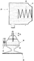
図2〜図7を用い、供給部50に滞留するのインクタンクへの気泡除去の過程を説明する。
【0075】
図2は、新しいインクタンク10が供給部50ないし記録ヘッド20に未装着状態である状態を示す。ここで、インクタンク10は完全にインクIが充填されている状態であり、ばね部材40による負圧が発生しているとともに、シート部材11がインクタンク外側へ突出した状態となっている。記録ヘッド20側においては、それまで装着されていたインクタンク10が空になっても供給部50に残ったインクを使用して記録が行われていたため、そのインクタンク側からエアが侵入し、供給部50におけるフィルタ23の上流領域において上部に気体が溜まっている状態となっている。
【0076】
図3は、図2の状態から、新たなインクタンク10を装着した瞬間の状態を示す。記録ヘッド20ないし供給部50側は大気に開放されている状態であるために、フィルタ23の上流領域の気体の圧力は大気圧と等しい。それに対し、インクタンク内は、ばね部材40により大気圧よりも低い圧力(負圧)となっている。これにより、インクタンク10を装着した瞬間にフィルタ23の上流領域の気体の一部がインク収納室12内に移動してその上部に溜まり、インク収納室12内と供給部50内とで圧力が平均化される。しかしながら、接続部51のインク流路53およびエア流路54内ではそれぞれインクがメニスカスを形成しており、そのメニスカスにより、圧力バランスがつりあった段階で気体の移動が停止する。供給部側の気体の容積によってはこの状態で気体除去が完了する場合もあるが、図示の場合には気体の容積が大きく、除去すべき気体が残存している。
【0077】
図4は、記録ヘッド20からインクを例えば滴として吐出させている状態を模式的に示している。インクを吐出させると、記録ヘッド20ないし供給部50内の負圧が高まり、接続部51に形成されるインクのメニスカスを破り、インクタンク10から供給部50に向けてインクが移動する。これに伴い、インク収納室12の内容積が減少し、シート部材11が圧力板14に規制されつつ下方に向けて変形する。これによりばね部材40が圧縮され、インク収納室12内の負圧も高まる。
【0078】
ここで、本実施形態では、インク流路53とエア流路54とは管径をほぼ等しくしてあり、そのため流路の圧力損失は記録ヘッド20ないし供給部50内の負圧に対して大きな差がなく、流路それぞれからインクが供給される。インク流路53のヘッド側開口53hがインクに接している図示の状態では、インク流路53からそのままインクが流れ込む一方、供給部50ないし記録ヘッド20内で生じた気泡はフィルタ上流領域に移動し、既に残存している気体とともに当該領域すなわち供給部50の上部に滞留している。この状態で、エア流路54のヘッド側開口54hの位置において、インクはメニスカスを形成するが、記録ヘッド20ないし供給部50内の負圧が高ければ滴下する。なお、本実施形態においては、記録動作に伴うインク吐出または記録動作以外の動作として行うインク吐出(予備吐出)により、接続部51内がインクで満たされた状態となるが、記録ヘッド20の吐出口形成面をキャップ部材で封止し、吸引ポンプにより、吐出口からインクを排出することによりこの状態を得ることもできる。
【0079】
図5は、インク吐出あるいは吐出口形成面側からのインク吸引が停止した状態を示す。この状態で、水頭差により、インク流路53では供給部50へのインク移動が生じるような力が発生し、エア流路54ではインクタンク10側へのエア排出が生じるような力が発生する。
【0080】
図6は、それらの力により、供給部50へのインク移動とインクタンク10側へのエア排出とが同時に進行している状態である。
【0081】
図7は、フィルタ上流領域内の気液界面がエア流路54のヘッド側開口54hの位置まで上昇した状態を示している。そしてこの状態で、インク移動およびエア排出が停止する。
【0082】
以上の通り、本実施形態によれば、接続部51の内部を2分割して2つの流路を設け、各流路のヘッド側開口位置の高さに差をつけることで、複雑な構成を必要とすることなく、フィルタ上流領域の滞留気体をインクタンク側に速やかに移送することが可能となる。
【0083】
また、インクタンクの交換操作後に若干のインク吐出あるいは吐出口形成面側からのインク吸引等を行えば供給部内に滞留していた気体を迅速かつ円滑にインクタンク側に移送して供給経路から排除できることになり、吐出口側から吸引動作を行うことによって気体を排除する場合のような大量のインク浪費が生じることもない。
【0084】
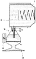
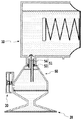
次に、図1、図8および図9を用いて、インクタンク10から記録ヘッド20へのインク供給の過程で、インク供給系内の圧力が所定値より小さくなったとき(負圧が所定値以上に高まったとき)の動作について説明する。
【0085】
インクタンク10内にインクが十分に満たされている図1の初期状態からインク消費(記録ヘッドへのインク供給)が始まり、これに追従してシート部材11ないし圧力板14はインク収納空間の内容積を減少させる方向(図1の左方向)に変位して行き、図8に示す位置に至る。
【0086】
この状態からさらにインク消費が進むと、インクタンク10ないし記録ヘッド20に至るインク供給系内は、内部のインク量が減少した分、圧力が減少(負圧が増大)する。
【0087】
そして、図9に示すように、インク供給系内の負圧と、バルブ室30内における弁規制部材によって作用する力等とがつりあった状態からさらにインク消費が継続されて負圧がさらに強まった瞬間に、連通口36が開放されて大気の流入が生じ、供給部50内にインクが取り込まれる。このときに供給部50内の負圧が緩和され連通口36が閉鎖される。このよう、バルブユニットによりインク流路およびヘッドには、所定の負圧が安定して印加され、ヘッドの吐出特性を良好にする。一方、インクタンク10内での負圧とのバランスにより、供給部50内の気体は、接続部51に形成される流路の少なくとも一方(ヘッド側開口54hのみが気体に接しているのであればエア流路54)を介して、インクタンク10内に移送される。
【0088】
以上のように、インクタンク10内に適宜気体の導入が行われることによって、収納するインクを効率的に、ほぼすべてを消費しきることができるようになる。
【0089】
また、バルブ室30を供給部50側に配置して外気の取り込みを可能とするとともに、供給部50側からインクタンク側に円滑に気体を移送できる構成としたことにより、交換頻度の高い部材であるインクタンク10の構成の簡略化および低廉化の面で有利である。
【0090】
さらに、上記インクタンク10の構成において、インクタンクの周囲環境の変化、例えば、温度上昇あるいは減圧等が生じても、シート部材11ないし圧力板14の左方への最大変位位置から初期位置までの間の容積分、収納空間内に取り込まれている空気の膨張が許容されるので、換言すれば当該容積分の空間がバッファ領域として機能するので、周囲環境の変化に伴う圧力の上昇を緩和し、吐出口からのインク漏出を効果的に防止することができる。
【0091】
また、初期充填状態からの液体導出に伴いインク収納空間の内容積が減少し、バッファ領域が確保されるまでは、気体が移送されてこないので、それまでに周囲環境の急激な変化や振動や落下などが生じてもインク漏れが発生しない。さらに、インク未使用状態から予めバッファ領域を確保しているのではないので、インク収納容器の容積効率も高く、コンパクトな構成とすることができる。
【0092】
また、インクに色材として顔料を含むものを用いた場合は、エアーがタンクに輸送される際に、顔料粒子の沈降を拡散させ、インクの保存安定性や吐出の信頼性を確保できる。
【0093】
(第2の実施形態)
以上の第1の実施形態によれば、供給部50に滞留した気体ないしはバルブ室30から供給部50に導入された気体を、インクタンク10および供給部50の内部の圧力のバランスによって接続部51を介しインクタンク10内に適宜移送することで、インクタンク10に収納されたインクを効率的に、ほぼすべて消費しきることができるようになる。
【0094】
図10(a)は、このようにインク収納部に収納していたインクをすべて使い切った後、交換のためにそのインクタンクを取り外した状態を、また同図(b)は、インクが完全に充填されている新たなインクタンクを装着するときの状態を示している。
【0095】
これらの図10(a)および(b)から明らかなように、また図2についても説明したとおり、インクタンク10が取り外された状態では、接続部51のタンク側開口53tおよび54hは大気に開放されるので、記録ヘッド20ないし供給部50側は大気に開放されている状態であるために、フィルタ23の上流領域の気体の圧力は大気圧と等しい。それに対し、インクタンク内は、ばね部材40により大気圧よりも低い圧力(負圧)となっている。これにより、インクタンク10を装着した瞬間にフィルタ23の上流領域の気体の一部がインク収納室12内に移動してその上部に溜まり、インク収納室12内と供給部50内とで圧力が平均化される。しかしながら、接続部51のインク流路53およびエア流路54内ではそれぞれインクがメニスカスを形成しており、そのメニスカスにより、圧力バランスがつりあった段階で気体の移動が停止する。供給部側の気体の容積によってはこの状態で気体除去が完了する場合もあるが、図示の場合には気体の容積が大きく、除去すべき気体が残存している。
【0096】
よって、記録ヘッド20からインクを吐出または強制排出させることで記録ヘッド20ないし供給部50内の負圧をが高め、接続部51に形成されるインクのメニスカスを破ってインクタンク10から供給部50に向けてインクを移動させる一方、供給部50側の気体をインクタンク10に移送させている。
【0097】
本構成の場合は、インクタンク交換に時間を要しない場合は問題ないが、インクタンクをはずして長期間放置した場合は、連通路が大気開放状態であるため、ノズルには正圧がかかり、振動などの外部要因も加わるなどすると、ノズルからインクが漏出するような場合がある。また、連通路からのインク蒸発でその部分のインク固着などが発生する場合もある。
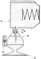
【0098】
図11は、上記構成において、さらに長期信頼性をも実現したもので、第2の実施形態に係る液体供給システムの模式的断面図である。この構成は、接続部51に設けられたインク流路53のタンク側開口53tおよびエア流路54のタンク側開口54tを閉塞可能なゴム等の弾性部材によるシャッタ57と、このシャッタ57を当該閉塞位置に位置づけるべく支持するためのばね58とを供給部50に設けたものである。
【0099】
かかる構成によれば、インクタンク10が取り外された状態では、それまでインクタンク10によって圧縮されていたばね58が伸長してシャッタ58がタンク側開口53tおよびタンク側開口54tを閉塞し、供給部50内の圧力が保持される。また、新たなインクタンク10が取り付けられる状態では、当該取り付け操作に伴ってばね59が圧縮され、接続部51がインクタンク10内に突入した状態で開口53tおよび54t側がインクタンク内で開放される。
【0100】
すなわち、インクタンクの交換操作中にわたってヘッド側の密閉状態が維持されるため、長時間インクタンクをはずした状態でも、インク固着などが発生せず、またヘッドへの負圧も維持されているため、ノズルからのインクたれ出し等の不具合が発生しない。
【0101】
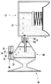
(第3の実施形態)
次に、インクタンクの構成をさらに簡略化・低廉化するための液体供給システムの構成について説明する。
【0102】
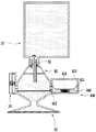
図12はかかる構成を説明するための液体供給システムの模式的断面図である。本実施形態が第1の実施形態と異なるのは、インクタンク10’には上述した負圧発生昨日およびバッファ機能を実現する手段を設けることなく、そのままインクを収納する形態とする一方、同様の機能を実現する機能室400を供給部50側に設けたものである。
【0103】
ここで、機能室400を構成する筺体内は、変形可能な可撓性膜(シート部材)411によって2つの空間に区画されており、当該区画された一方の空間が連通口432を介して大気に開放され、大気圧と等しくされている。また、他方の空間は連通口413を介して供給部50に接続され、インク連通している。
【0104】
シート部材411の中央部分は平板状の支持部材である圧力板414によって形状が規制されており、その周縁部分が変形可能となっている。そして、このシート部材411は、予めその中央部分が大気開放側の空間に向かって凸状に形成されていて、側面形状がほぼ台形となっている。また、インク連通側空間内には、圧力板414を介してシート部材411を図の上方向に付勢する押圧力を作用することで、記録ヘッドのインク吐出部に形成されるメニスカスの保持力と平衡して記録ヘッドのインク吐出動作が可能な範囲にある負圧を発生させる圧縮ばね形態のばね部材440が設けられている。
【0105】
すなわち、機能室400の内部は、第1実施形態におけるインクタンク10の内部とほぼ同様に構成され、同様の機能を果たすものである。なお、図12の状態は、インクタンク10’内にほぼ完全にインクが充填された状態を示しているが、この状態でばね部材440は圧縮された状態にあり、インク供給系内には適切な負圧が生じているものとする。
【0106】
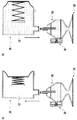
図12〜図15を用いて本実施形態の動作を説明する。
図13は図12の初期状態からインクを排出し始めた状態を示し、まずシート部材411ないし圧力板414が変形して、機能室400のインク連通側空間の内容積が収縮し、バッファ領域が確保される。
【0107】
図14はこの後、さらにインクが排出されて機能室400のインク連通側空間を含む液体供給系内の負圧が高まることでバルブ室30から供給部50内に外気を取り入れ、さらにインクタンク10’に対して気体を移送し始めた状態である。
【0108】
図15は、供給部50に滞留した気体ないしはバルブ室30から供給部50に導入された気体を、インクタンク10’に適宜移送する一方、供給室50内にインクを移動させることで、インクタンク10’に収納されたインクを効率的に消費して行く状態の説明図である。そして、このような状態で温度の上昇や減圧などの環境変化が生じた場合には、インクタンク10’ないし供給部50内の気体が膨張し、インク供給系内の圧力が高まることになるが、それを機能室400が果たすバッファ機能が吸収するので、記録ヘッド20に不都合な加圧力を作用することを防止できることになる。
【0109】
本実施例は、消耗品であるインクタンクに機能部品をほとんど設けず、ヘッド側に設けたことにより、消耗品の価格を極めて安価にすることが可能である。それだけでなく、ヘッド部に大気の導入を許可して、逆に供給路内のインクや空気の排出を許可しない一方向バルブと、環境変化に対応して所定の負圧を維持するバッファを設けることにより、バルブからの大気導入の際に生じる負圧の変動(リップル)に対し、バッファが瞬時にリップルを平滑化させるコンデンサの役割をはたすため、ヘッドに対しての負圧変動がより抑えられ、ヘッドの吐出特性を極めて安定させるものである。
【0110】
(インクジェット記録装置の構成例)
図16は、本発明を適用可能なインクジェット記録装置の構成例を説明するための図である。
【0111】
本例の記録装置150はシリアルスキャン方式のインクジェット記録装置であり、ガイド軸151,152によって、キャリッジ153が矢印Aの主走査方向に移動自在にガイドされている。キャリッジ153は、キャリッジモータおよびその駆動力を伝達するベルト等の駆動力伝達機構により、主走査方向に往復動される。キャリッジ153には、上記のいずれかの実施形態を可とし、記録ヘッドないし供給部と、これに装着されてインクを供給するインクタンクとからなる液体供給システム154が搭載される。記録媒体としての用紙Pは、装置の前端部に設けられた挿入口155から挿入された後、その搬送方向が反転されてから、送りローラ156によって矢印Bの副走査方向に搬送される。記録装置150は、記録ヘッドを主走査方向に移動させつつ、プラテン157上の用紙Pの記録領域に向かってインクを吐出させる記録動作と、その記録幅に対応する距離だけ用紙Pを副走査方向に搬送する搬送動作と、を繰り返すことによって、用紙P上に順次画像を記録する。
【0112】
なお、記録ヘッドは、上述のように、インクを吐出するためのエネルギとして、電気熱変換体から発生する熱エネルギを利用するものであってもよい。その場合には、電気熱変換体の発熱によってインクに膜沸騰を生じさせ、そのときの発泡エネルギによって、インク吐出口からインクを吐出することができる。また、記録ヘッドにおけるインクの吐出方式は、このような電気熱変換体を用いた方式のみに限定されず、例えば、圧電素子を用いてインクを吐出する方式等であってもよい。
【0113】
キャリッジ153の移動領域における図16中の左端には、キャリッジ153に搭載された記録ヘッドのインク吐出口の形成面と対向する回復系ユニット(回復処理手段)158が設けられている。回復系ユニット158には、記録ヘッドのインク吐出口のキャッピングが可能なキャップと、そのキャップ内に負圧を導入可能な吸引ポンプなどが備えられており、インク吐出口を覆ったキャップ内に負圧を導入することにより、インク吐出口からインクを吸引排出させて、記録ヘッドの良好なインク吐出状態を維持するための回復処理を行うことができる。また、画像形成とは別に、キャップ内に向かってインク吐出口からインクを吐出させることによって記録ヘッドの良好なインク吐出状態を維持する回復処理(予備吐出処理」ともいう)を行うこともできる。
【0114】
(その他)
なお、インクタンクおよび供給部間の気液交換を円滑にするための接続部の構成、特に気体の移送に伴うインク移動の開始を円滑に行わせるためのインク流路の構成は、上述のようにそのヘッド側開口を鉛直方向に関して相対的に低い位置となるようにする構成に限られない。
【0115】
インク流路のヘッド側開口の位置とエア流路のヘッド側開口の位置に高さの差を設けなくても、例えば、上述のように内部を2分割して接続部51に2つの流路を設けるとともに、一方のヘッド側開口の一部が供給部の内壁面に接するようにしたり、あるいは一方の流路に沿って微細な溝を形成する部分を併設し、さらにその溝がヘッド側開口からさらに延長して供給部内方に突出するようにしたりすることで、当該ヘッド側開口部において高い圧力を作用するメニスカスが形成されなくなるようになし、これにより当該流路からインクが供給部内に流れ落ち易くなるようにすることができる。
【0116】
また、当該開口部分を拡大した形状とすること、流路間で径に差をつけること、あるいは材質の適切な選択や表面処理を行うことで流路内面の状態が流路間で異なっているようにすることなどによっても、同様の効果が期待できる。
【0117】
加えて、記録ヘッド側ないしインク供給部側にインク流路およびエア流路を有する接続部を設ける代わりに、インクタンク側にこれを設け、供給部内に突入可能な構成とすることもできる。
【0118】
また、内部を2分割して2つの流路を形成した接続部とするのではなく、各流路を形成する別体の部材としてもよい。さらに、流路の数は2つに限られず、3以上設けられるものでもよい。また、内部を複数に分割して複数の流路を形成する接続部とする場合にも、上例のように流路間の隔壁を直線状に形成するのみならず、同心円状に形成することで多重管構成の接続部とすることができる。
【0119】
さらに、内部を複数に分割して複数の流路を形成する接続部とする場合、気体の移送とインクの移動とが相互に干渉して円滑かつ迅速な気液交換を阻害しない限り、各流路が完全に区画されていなくても良い。
【0120】
上述のインク供給システムの諸実施形態では、基本的にいずれも吸収体等にインクを保持させずにそのまま貯留ないし供給されるようにした構成を採用する一方、可動部材(シート部材、圧力板)とこれを付勢するばね部材とにより負圧発生手段を構成するとともに供給システム内を密閉構造とすることで、記録ヘッドに対して適切な負圧を作用するようにした。
【0121】
かかる構成は、吸収体により負圧を発生させる従来技術の構成に対して、容積効率が高く、かつインク選定の自由度も向上できるものである。また、そればかりでなく、近年の記録の高速化に伴って求められるインク供給の高流量化や安定化の要望にも好ましく応え得るものである。しかし、インクタンクの一部に吸収体が設けられている構成であっても、本願発明を適用できることは勿論である。
【0122】
また、供給経路に滞留する気体を排除する目的に対しては、記録ヘッドから最も離れた最上流位置であるインクタンクにこれを移送するものとし、そのために複数の流路を介してインクタンクとインク供給経路とを連結するとともに、両者の圧力のバランスを利用することでインクタンクからのインク導出とインクタンクへの気体導入とが並行して行われるようにした。
【0123】
かかる構成によれば、供給経路内の滞留気体を、複雑な装置を必要とせず、部品点数の増加が少なく簡単な構造でありながら、円滑かつ迅速にインクタンク側に排除することができる。また、排除のタイミングも、気体がある程度蓄積すると圧力のバランスに従って自ずと行われるため、気体排除の信頼性が高いものである。また、かかる構成は、インク供給経路すなわち供給部に外気を導入することで負圧維持を行うための弁機構を設けた場合にも、導入された気体が多くなれば自ずと排除されるために有利な構成であり、これはインクタンクによって負圧を発生する場合より一層構成の簡略化および低廉化に資することができる構成である。
【0124】
また、気体排除の過程において、常にインクタンクの負圧を維持しているのでインクジェット記録ヘッドのインク吐出口などからの液体漏洩を確実に防止することができる。さらには、気体をインクタンク側に排除することによって、記録ヘッドの吐出口側からインク吸引を行うことで気体を排除する方法に比較してインク消費量を格段に減少させることができ、インク浪費を抑えて、ランニングコストの低減にも貢献するものである。
【0125】
加えて、供給経路に対して着脱可能に構成されたインクタンクを用いる場合において、従来は、交換操作時に供給経路側に気体が侵入することを防止するために、供給経路がインクで満たされている状態で、すなわちインクを完全に消費しきる前にインクタンクの交換を行っている場合が多かった。しかし上記構成によれば、交換操作時に供給経路内に気体が侵入しても、新たなインクタンクを装着すればそのインクタンクに対して容易に排除できるので、インクが完全に消費された後に交換を行うことができ、またこれにより、ランニングコストのさらなる低減できるのみならず、環境問題に対しても資するところが大きい。
【0126】
さらに、上述の実施形態においてはいずれも、通常の使用時の姿勢においてインクタンクを最も高所に配置し、供給部ないし記録ヘッドが低所に配置されている。これは、気液交換を迅速かつ円滑に、かつ簡単な構成で行う上で非常に好ましい配置である。
【0127】
なお、インクタンクの構成にもよるが、インクタンクに導入された気体は、これがインク供給経路に戻らず、インク供給が阻害されない位置であれば、インクタンク内のどこに貯留されてもよい。しかし、インクを吸収体などに含浸させずにそのまま貯留するようにした上記実施形態の構成は、導入された気体がそのままインクタンク内の最上部に位置することになるので、好ましいものである。
【0128】
そしてこのように、インクタンク内に吸収体が存在しない場合には、タンクの容積そのものがインクの容量となりうるので、必要以上にインクタンクを大きくする必要がなく、またタンクの形状も比較的自由に設計できるのである。
【0129】
また、以上の説明では本実施形態の記録方式として、シリアル型のインクジェット記録装置を適用してきたが、本発明および本実施形態はこれに限定されるものではない。また、シリアル型でなくライン走査型の記録装置であっても本発明および本実施形態を適用することは可能である。さらに、液体供給システムは、インクの色調(色や濃度など)に対応して複数設けることができるのは言うまでもない。
【0130】
【発明の効果】
以上説明したように、本発明によれば、液体使用部分に対して密閉構造を持つ液体供給システムにおいて、液体使用動作および液体供給動作の障害となる気体を、構造の複雑化を伴うことなく液体供給経路から迅速かつ円滑に排除できるようになった。
【0131】
また、インクジェット記録装置に適用した場合、密閉構造のインク供給経路内に残留する気体を円滑かつ迅速にインクタンク側に移送させると共に、記録装置の実使用時においても、滞留気泡に起因する問題点、すなわちインク供給の不良や混入気泡による吐出口の目詰まり等に起因した記録不良を防止できる。
【0132】
また、インクに色材として顔料を含むものを用いた場合は、エアーがタンクに輸送される際に、顔料粒子の沈降を拡散させ、インクの保存安定性や吐出の信頼性を確保できる。
【0133】
さらに、本発明は、インクタンクへの気体の上記排除性能を活用することにより、インク供給系内の負圧を好ましい状態に維持するために外気を導入する機構をインク供給経路側に設け、これによってインクタンクの構成の簡略化および低廉化を図ることができる。
【0134】
以上より、ヘッドへの負圧を安定化した状態でインク供給できる本発明によって、印字性能と信頼性およびコストダウンが同時に実現可能になった。
【図面の簡単な説明】
【図1】本発明の第1の実施形態による液体供給システムの模式的断面図である。
【図2】第1の実施形態における気体除去過程を説明するための図であり、新しいインクタンクが供給部ないし記録ヘッドに未装着である状態を示す模式的断面図である。
【図3】第1の実施形態における気体除去過程を説明するための図であり、図2の状態から、新たなインクタンクを装着した瞬間の状態を示す模式的断面図である。
【図4】第1の実施形態における気体除去過程を説明するための図であり、記録ヘッドからインクを吐出させている状態を示す模式的断面図である。
【図5】第1の実施形態における気体除去過程を説明するための図であり、図4のインク吐出あるいは排出が停止した状態を示す模式的断面図である。
【図6】第1の実施形態における気体除去過程を説明するための図であり、図6の状態からインク移動と気体排出とが同時に進行している状態を示す模式的断面図である。
【図7】第1の実施形態における気体除去過程を説明するための図であり、インク移動および気体排出が停止した状態を示す模式的断面図である。
【図8】第1の実施形態における負圧調整のための外気取入れ動作を説明するための説明図である。
【図9】第1の実施形態における負圧調整のための外気取入れ動作を説明するための説明図である。
【図10】(a)および(b)は、第1の実施形態の構成によるインクタンク交換操作時の状態を説明するための説明図である。
【図11】本発明の第2の実施形態に係る液体供給システムの構成を説明するための模式的断面図である。
【図12】本発明の第3の実施形態に適用されるインク供給システムの構成を説明するための模式的断面図である。
【図13】第3の実施形態に係る液体供給システムの動作を説明するための模式的断面図である。
【図14】第3の実施形態に係る液体供給システムの動作を説明するための模式的断面図である。
【図15】第3の実施形態に係る液体供給システムの動作を説明するための模式的断面図である。
【図16】本発明を適用可能なインクジェット記録装置の構成例を示す斜視図である。
【符号の説明】
10 インクタンク
11 シート部材
12 インク収納室
13 連通口
14 圧力板
17 封止部
19 固定部材
20 記録ヘッド
22 フィルタ
30 バルブ室
31 バルブ室シート部材
34 バルブ室圧力板
35 バルブ室ばね部材
32,36 連通口
37 シール部材
40 ばね部材
50 供給部
51 接続部
53 インク流路
54 エア流路
150 インクジェット記録装置
154 液体供給システム
153 キャリッジ
158 回復系ユニット
430 機能室
431 バルブ室シート部材
434 バルブ室圧力板
435 バルブ室ばね部材
432,436 連通口[0001]
TECHNICAL FIELD OF THE INVENTION
The present invention, for example, supplies a liquid such as ink to a recording head or a pen as a liquid using unit from an ink tank or the like as a liquid storing unit without waste and stably, and further includes a gas existing in the liquid using unit. The present invention relates to a liquid communication structure for discharging liquid into a liquid storage unit, a liquid supply system using the same, and an ink jet recording apparatus using the system.
[0002]
[Prior art]
A liquid using apparatus, for example, an ink jet recording apparatus that forms an image on a recording medium by applying a liquid ink to the recording medium using an ink jet recording head has a relatively small noise at the time of recording and a small dot. Since it can be formed at a high density, it is used in many printings including color printing in recent years. As one form of such an ink jet recording apparatus, an ink jet recording head that receives supply of ink from an ink tank attached inseparably or separably, and a recording head mounted with the recording head in a predetermined direction with respect to a recording medium. A carriage for relatively scanning, and a conveying unit for relatively conveying (sub-scanning) the recording medium relative to the recording head in a direction orthogonal to the predetermined direction, and ejecting ink during a main scanning process of the recording head. In some cases, recording is performed by causing Furthermore, a recording head capable of discharging black ink and each color ink such as yellow, cyan, magenta, etc. is mounted on the carriage, and not only monochrome printing of a text image with black ink, but also changing the discharge ratio of each ink. Some have enabled full-color printing.
[0003]
In such an ink jet recording apparatus, it is problematic to appropriately discharge gas such as air that has entered or is entering the ink supply path.
[0004]
Here, the gas entering the supply system is roughly classified into four types of generation factors.
1) those that enter from the ink discharge port of the print head or are generated by the discharge operation;
2) gas dissolved inside the ink is separated,
3) those that enter by gas permeation from the outside through the material constituting the supply path, and
4) What comes in when replacing the ink tank in the form of a cartridge,
It is.
[0005]
By the way, the ink flow path formed in the ink jet recording head is very fine, and therefore the ink supplied from the ink tank to the recording head is in a clean state in which foreign matter such as dust is not mixed. Is required. That is, in the case where foreign matter such as dust is mixed in, there is a problem that the foreign matter is clogged in a particularly narrow discharge port or a liquid path portion directly communicating with the ink flow path in the recording head. It may not be possible to perform a proper ink ejection operation, and it may be impossible to recover the function of the recording head.
[0006]
Therefore, in general, a filter member for removing foreign matter is arranged in an ink flow path between the print head and an ink supply needle protruding into the ink tank, and the filter member can prevent foreign matter from entering the print head. Often configured.
[0007]
On the other hand, in recent years, in order to realize high-speed printing, the number of ejection ports for ejecting ink has been increasing, and a drive signal applied to an element that generates energy for ejecting ink also has an increasingly higher frequency. Things are being adopted. For this reason, the consumption amount of ink per unit time is also rapidly increasing.
[0008]
Accordingly, the amount of ink passing through the filter member naturally increases, but in order to reduce the pressure loss due to the filter member, it is effective to partially expand the supply path and arrange a large-area filter member. is there. For this reason, if air bubbles are mixed in the supply path, the air bubbles are likely to stay in the space on the upstream side of the filter member in the enlarged portion and cannot be discharged, which causes a problem that the smooth supply of ink is hindered. . Further, the gas accumulated inside the supply path may become fine bubbles and mix into the ink guided to the ejection port, which may cause problems such as non-ejection of the ink.
[0009]
Therefore, it is highly desirable that the air remaining in the ink supply path be quickly removed, and there are several methods for that purpose.
[0010]
One of them is to perform a cleaning operation as described below.
The ink jet recording head performs printing by, for example, ejecting a liquid ink as a droplet from an ejection port arranged opposite to a recording medium, so that the ink viscosity increases due to evaporation of the ink solvent from the ejection port. Solidification of the ink, adhesion of dust to the discharge port, and mixing of bubbles into the liquid path inside the discharge port may cause clogging or the like of the discharge port, resulting in poor printing.
[0011]
For this reason, in the ink jet recording apparatus, a capping means for covering the discharge port of the recording head during the non-printing operation and the surface of the recording head having the discharge port (discharge port forming surface) are cleaned as necessary. A wiping member is provided. The capping means not only functions as a lid for preventing drying of the ink of the above-described ejection port when printing is stopped, but also when the ejection port is clogged, covers the ejection port forming surface with a cap member, for example, By applying a negative pressure by a suction pump communicating with the inside of the cap member, the ink is sucked and discharged from the discharge port to cause clogging due to solidification of the ink in the discharge port, and ink discharge due to thickened ink or mixed bubbles in the liquid path. It also has a function to eliminate defects.
[0012]
The forcible ejection of ink to eliminate these ink ejection failures is also referred to as a cleaning operation, which is performed when printing is restarted after a long period of suspension of the apparatus, or when the quality of a recorded image is deteriorated by a user. This process is performed when the cleaning switch is operated upon recognizing that the ink is forcibly discharged, and is a process that involves a wiping operation of the ejection port forming surface by a wiping member formed of an elastic plate such as rubber after the ink is forcibly discharged. .
[0013]
Then, at the time of initial filling for filling ink into the flow path or liquid path of the recording head for the first time, or at the time of a cleaning operation performed when the ink tank is replaced, a suction pump is applied to the capped discharge port forming surface. Attempts have been made to apply a large negative pressure by driving the ink at a high speed, thereby obtaining a high flow velocity in the ink supply path to discharge the retained bubbles.
[0014]
However, the problem of the increase in the area of the filter member for suppressing the dynamic pressure of the filter member and the problem with the residual air bubbles are based on incompatible effects, and it is extremely difficult to remove the residual air bubbles from the discharge port side with a suction pump. Have difficulty. In other words, as a condition for bubbles to pass through the filter due to the flow of ink by the suction pump, a predetermined flow rate is required for the ink passing through the filter. To generate this, a large pressure difference must not be generated on both sides of the filter. Not be. To realize this, it is usually considered to reduce the filter area to increase the flow path resistance or to increase the flow rate of the suction pump. However, if the filter is reduced, the supply performance to the head is impaired, and If the gas is to be removed at a flow rate, a large amount of ink is discharged, and the ink is unnecessarily consumed.
[0015]
Therefore, two other methods of removing bubbles are considered: a method of directly discharging the air to the outside, and a method of moving the ink to the ink tank side and keeping the ink at a site in the tank which does not hinder the ink supply. Of these, the former has a configuration in which a communication port to the outside is provided in the supply path, but this is not a preferable method for the following reasons.
[0016]
That is, in an ordinary ink jet recording apparatus, a capillary force generating member such as an absorber is provided in an ink tank or a flexible ink storage is provided in order to prevent undesired leakage of ink from an ejection port. In many cases, a negative pressure is generated in the ink storage space of the ink tank by arranging an elastic member such as a spring on the bag and applying a biasing force in the direction of expanding the internal volume. In such a case, if a simple communication port is arranged in the supply path for removing bubbles, the negative pressure will be released due to the intrusion of air from the communication port. This is because it is necessary to provide a pressure adjusting valve and the like, and the structure of the ink supply system and the structure of the recording apparatus using the ink supply system become complicated and large. Also, in order to prevent ink from leaking from the communication port for discharging air bubbles, it is necessary to provide a water-repellent film or the like that allows gas to pass but not liquid, or the communication port only when bubbles remain. This is because a device (such as a bubble amount detection mechanism or a communication port opening / closing mechanism) that opens and discharges air is required, and this increases the manufacturing cost and the complexity and size of the structure.
[0017]
On the other hand, consider moving bubbles to the ink tank side. At this time, if the amount of ink corresponding to the volume of the bubbles moving to the ink tank can be transferred to the head side, there is no change in the volume of the ink tank, and the generated negative pressure is kept constant, and the ejection port is discharged to the recording head. This is preferable because a negative pressure balanced with the holding force of the meniscus formed on the surface can be applied. Further, if the ink tank is of a cartridge type, it can be replaced with a new one when the remaining amount of ink to be stored is exhausted, so that it can be said that the configuration can completely remove gas from the ink supply system. .
[0018]
Here, in order to smoothly transfer the gas to the ink tank side, the upstream portion of the filter member in the enlarged portion is formed, for example, in a tapered shape further upstream, that is, the ink supply from the ink supply needle. It is also considered effective to form the passage so that it does not suddenly expand toward the position where the filter member is provided.
[0019]
However, in an ink jet recording apparatus widely used for consumer use, an ink tank in the form of a cartridge containing black ink and color ink can be detachably mounted to a recording head or a carriage on which the recording head is mounted. In many cases, for example, the ink cartridge is configured such that a hollow ink supply needle mounted upward on a carriage is inserted into the ink cartridge so that ink can be supplied to the recording head. Therefore, the diameter of the ink supply needle connecting the ink cartridge and the recording head becomes a problem. In other words, a thin supply needle is required in order to simplify the operation of mounting the cartridge. However, in the case of a thin tube, the meniscus force is increased, so that bubbles cannot be moved smoothly.
[0020]
By the way, some proposals have been made on a mechanism for moving gas to the ink tank side.
[0021]
For example, in Patent Document 1, the recording head side is divided into a first chamber having an air communication port and a second chamber having a capillary force generating member, and the first chamber and the ink tank are opened on the first chamber side. There is disclosed a configuration in which air is supplied from one of the communication paths to the ink tank side by connecting two or more communication paths having different heights. In such a configuration, a negative pressure is applied to the head by a head difference between the first chamber and the second chamber, or a capillary force generating member disposed in the second chamber, and an air communication port is provided in the first chamber. Can be arranged.
[0022]
However, the configuration of Patent Literature 1 aims to introduce the atmosphere in accordance with the ink supply in order to use up the ink in the ink tank that does not deform, and to eliminate bubbles remaining in the ink supply path. Not something. In particular, the first chamber serving as the ink supply path is open to the atmosphere through the atmosphere communication port, so that no negative pressure is generated. The first chamber is always in contact with the atmosphere, and a predetermined negative pressure is applied to the head as in the present application. Therefore, unlike a system in which the ink storage unit and the ink supply unit are substantially sealed, there is no recognition of the problem of gas mixing peculiar to the sealed supply system. That is, the technique disclosed in the above document cannot be applied to transfer the gas from the ink supply path, particularly from the second chamber or the recording head side, to the ink tank.
[0023]
Further, as another proposal, in Patent Document 2, when the negative pressure generating member storage chamber and the liquid storage chamber are made separable, a gas priority introduction path and a liquid discharge path are arranged in a communication part connecting the two. In addition, a configuration has been disclosed in which gas can be reliably introduced. However, this document also discloses a configuration in which a capillary force generating member and an air communication port are arranged between the ink tank and the recording head. Is an ink supply path of an open-to-atmosphere system that freely enters and exits, and the technique disclosed in the document cannot be applied even from the viewpoint of eliminating bubbles remaining in the ink supply path peculiar to a closed system.
[0024]
Further, Patent Document 3 discloses an ink container (ink container 50) having a liquid outlet pipe (drain conduit 66, 72, 74) and a gas inlet pipe (vent conduit 76, 82, 84) projecting downward. The liquid outlet pipe has an upper opening on the bottom surface of the inner wall of the storage container, and the gas outlet pipe has an opening disposed inside the storage space of the storage container. An object of the technique disclosed in the document is a configuration of a system for refilling ink in a member (14) having reservoirs (16, 18, 20), using an ink supply path or ink downstream of the reservoir. It is not intended to remove air bubbles remaining in the portion where the air bubbles are generated. Also, it is considered that if a meniscus is formed in the liquid outlet pipe and the gas inlet pipe since the lower opening heights thereof are equal to each other, the liquid or gas cannot move. Further, since there is no communication port for communicating the inside of the ink container and the
[0025]
Further, in Patent Document 4, a replenishment tank for replenishing ink with a reservoir tank having a negative pressure generating member storage chamber and an ink storage chamber can be connected, and an upper part and a lower part of a space of the ink storage chamber are provided. When the replenishment tank is connected at the lower part, ink is introduced from the replenishment tank into the ink storage chamber via the lower liquid communication pipe, while air is supplied from the ink storage chamber to the replenishment tank side via the upper gas communication pipe. A configuration adapted to be introduced is disclosed. However, even in this document, there is essentially no difference from Patent Documents 1 and 2 in the configuration in which the negative pressure generating member and the air communication port are arranged between the ink storage chamber and the recording head. The technique disclosed in the document cannot be applied without even the viewpoint of eliminating bubbles remaining in the ink supply path.
[0026]
[Patent Document 1]
JP-A-5-96744
[Patent Document 2]
JP-A-11-309876
[Patent Document 3]
US Pat. No. 6,347,863
[Patent Document 4]
JP-A-10-29318
[Problems to be solved by the invention]
As described above, Patent Documents 1 to 4 disclose the introduction of gas into the ink tank. However, the gas remaining in the ink supply path having a closed structure in use is smoothly transferred to the ink tank side. Neither of the purposes of transfer and retention to the United States was met.
[0031]
Therefore, the present invention provides a liquid supply system having a closed structure with respect to a liquid use part, which quickly and smoothly removes gas that hinders the liquid use operation and the liquid supply operation from the liquid supply path without complicating the structure. The purpose is to be able to eliminate.
[0032]
Another object of the present invention is to transfer the gas remaining in the ink supply path of the closed structure to the ink tank side smoothly and promptly, and to cause a problem caused by stagnant air bubbles even when the recording apparatus is actually used. That is, an object of the present invention is to provide an ink jet recording apparatus which does not cause recording failure due to defective ink supply or clogging of an ejection port due to a mixed bubble.
[0033]
It is another object of the present invention to utilize the above-described performance of transferring gas to the ink tank, thereby simplifying the configuration of the ink tank and reducing the cost.
[0034]
[Means for Solving the Problems]
Therefore, the liquid of the present invention has a liquid communication structure for liquid communication between a liquid storage unit for storing a liquid and a liquid using unit using the liquid, wherein the liquid communication structure is configured such that each of the liquid storage unit and the liquid storage unit A plurality of communication paths that communicate with the liquid use unit, wherein the liquid storage unit side is closed by the presence of the liquid in the liquid storage unit, and the liquid use unit side is the presence of the liquid in the liquid use unit. Forming a substantially closed space, and in a state where gas is present in the closed space, the gas can be transferred to the liquid storage unit through a part of the plurality of communication paths, and A valve mechanism is provided at a portion forming a space, and is provided with a valve mechanism capable of introducing outside air into the liquid supply path in accordance with the supply of the liquid to the liquid using section.
[0035]
Here, in a state where gas is present in the vicinity of at least a part of the plurality of communication passages on the side of the liquid use part, the liquid storage part is separated from the liquid storage part through a part of the plurality of communication paths. At the same time as the liquid moves, the gas is transferred to the liquid storage unit via another part of the plurality of communication paths.
[0036]
Then, in a state where gas is present in the vicinity of at least a part of the plurality of communication paths near the liquid use part, the liquid from the liquid storage part to the liquid use part through a part of the plurality of communication paths. As the liquid moves and the gas pressure in the liquid using section increases, the gas is transferred to the liquid storage section via a communication path of another part of the plurality of communication paths. Things.
[0037]
In the above, in the posture at the time of using the liquid, in the vertical direction, the liquid communication structure is positioned substantially lower than the liquid storage portion, and further positioned substantially higher than the liquid usage portion. can do.
[0038]
Further, the present invention resides in a liquid supply system that can supply the liquid from the liquid storage section to the liquid use section by using any one of the liquid communication structures described above.
[0039]
Here, the liquid storage section defines a liquid storage space, and at least a movable member that can be displaced in a direction that reduces the internal volume of the storage space with the supply of the liquid to the liquid use section. Further, the liquid storage portion may include an urging member for urging the movable member in a direction opposite to the direction of the displacement.
[0040]
Alternatively, the liquid storage section is provided in a state of liquid communication with the closed space to define a liquid storage space, and the liquid storage section supplies the liquid to the liquid use section through the liquid supply path. At least a part of the movable member can be displaced in a direction to reduce the volume of the space, and an urging member for urging the movable member in a direction opposite to the direction of the displacement can be provided.
[0041]
In the above, the valve mechanism may introduce the outside air when the negative pressure in the liquid supply path increases to a predetermined value or more.
[0042]
Further, the liquid storage section can be detachably attached to the liquid supply path via the plurality of communication paths.
[0043]
Here, a shutter member capable of closing the openings of the plurality of communication passages on the liquid storage unit side when the liquid storage unit is not mounted can be provided.
[0044]
In the above, the liquid using section is an ink jet recording head for performing recording by discharging ink as the liquid, and the ink can be guided to the ink jet recording head.
[0045]
Here, the recording head may be integrally configured to be separable.
[0046]
Further, the present invention uses such a liquid supply system, and in a posture during use, the plurality of communication paths are positioned substantially higher than the liquid supply path in the vertical direction, and further, the liquid storage unit Exists in an ink jet recording apparatus that performs recording while holding the liquid supply system so as to be positioned substantially higher than the plurality of communication paths.
[0047]
Furthermore, the present invention resides in a liquid tank which constitutes the liquid storage portion used in the liquid supply system of any of the above-described embodiments, and is connectable to the liquid supply path via the plurality of communication paths.
[0048]
Further, in the liquid supply system, the valve mechanism may permit introduction of the outside air into the liquid supply path, and may not permit movement of the liquid or gas in the opposite direction.
[0049]
Furthermore, the present invention relates to an ink jet recording head for performing recording by discharging ink as a liquid, characterized by integrally having any one of the above-described liquid communication structures.
[0050]
Here, the ink jet recording apparatus may have a form of a cartridge that is detachable from the ink jet recording apparatus.
[0051]
In addition, the liquid tank of the present invention has the form of a cartridge that forms the liquid storage portion connected to the liquid communication structure of any one of the above forms, and is connectable to the liquid communication structure via the plurality of communication passages. It is characterized by the following.
[0052]
Further, the liquid tank of the present invention has a form of a cartridge connectable to the liquid communication structure of the ink jet recording head through the plurality of communication paths.
[0053]
BEST MODE FOR CARRYING OUT THE INVENTION
Hereinafter, some embodiments in which the present invention is applied to an inkjet recording apparatus will be described with reference to the drawings.
[0054]
In this specification, the term “record” refers to not only a case where significant information such as characters and figures are formed, but also a matter that is significant or insignificant, and is also manifested so that humans can perceive it visually. Regardless of whether or not the image, pattern, pattern, or the like is formed on a recording medium widely, or when the recording medium is processed.
[0055]
In addition, the “recording medium” includes not only paper used in general recording apparatuses but also a wide range of materials that can accept ink, such as cloth, plastic films, metal plates, glass, ceramics, wood, and leather. It should be noted that, hereinafter, it is also referred to as “paper” or simply “paper”.
[0056]
In the following embodiments, ink is described as an example of the liquid used in the liquid supply system of the present invention. However, the applicable liquid is not limited to ink, and is applicable to, for example, the inkjet recording field. Needless to say, it includes a processing liquid for the recording medium.
[0057]
(1st Embodiment)
FIG. 1 is a schematic sectional view of a liquid supply system according to a first embodiment of the present invention.
[0058]
The ink supply system of the embodiment shown in FIG. 1 generally includes an
[0059]
The
[0060]
In the
[0061]
The shape of the central portion of the
[0062]
In the ink storage space, a pressing force for urging the
[0063]
The state shown in FIG. 1 shows a state in which the ink storage space is almost completely filled with ink. However, in this state, the
[0064]
The connection between the
[0065]
The
[0066]
The ink supply path in the
[0067]
The
[0068]
The peripheral portion of the
[0069]
Inside the
[0070]
Here, as the
[0071]
The
[0072]
The
[0073]
In the illustrated example, the
[0074]
The process of removing air bubbles from the ink tank staying in the
[0075]
FIG. 2 shows a state in which a
[0076]
FIG. 3 shows a state at the moment when a
[0077]
FIG. 4 schematically shows a state where ink is ejected from the
[0078]
Here, in the present embodiment, the diameters of the
[0079]
FIG. 5 shows a state in which ink ejection or ink suction from the ejection port forming surface side has stopped. In this state, due to the head difference, a force is generated in the
[0080]
FIG. 6 shows a state in which the movement of the ink to the
[0081]
FIG. 7 shows a state in which the gas-liquid interface in the upstream region of the filter has risen to the position of the head-
[0082]
As described above, according to the present embodiment, the inside of the
[0083]
Also, if a small amount of ink is ejected or the ink is sucked from the ejection port forming side after the ink tank replacement operation, the gas remaining in the supply section is quickly and smoothly transferred to the ink tank side and removed from the supply path. As a result, a large amount of ink is not wasted as in the case of removing gas by performing a suction operation from the ejection port side.
[0084]
Next, referring to FIGS. 1, 8, and 9, when the pressure in the ink supply system becomes smaller than a predetermined value in the process of supplying the ink from the
[0085]
Ink consumption (supply of ink to the recording head) starts from the initial state in FIG. 1 in which the
[0086]
As the ink consumption further progresses from this state, the pressure in the ink supply system from the
[0087]
Then, as shown in FIG. 9, the ink consumption is further continued from the state where the negative pressure in the ink supply system and the force acting by the valve regulating member in the
[0088]
As described above, by appropriately introducing gas into the
[0089]
In addition, the
[0090]
Further, in the configuration of the
[0091]
In addition, since the internal volume of the ink storage space is reduced due to the derivation of the liquid from the initial filling state and gas is not transferred until the buffer area is secured, sudden changes in the surrounding environment, vibration and No ink leakage occurs even if a drop occurs. Further, since the buffer area is not reserved in advance from the state where the ink is not used, the volume efficiency of the ink container is high, and a compact configuration can be achieved.
[0092]
In addition, when a pigment containing pigment is used as the ink, when the air is transported to the tank, the sedimentation of the pigment particles is diffused, and the storage stability of the ink and the reliability of the ejection can be secured.
[0093]
(Second embodiment)
According to the first embodiment described above, the gas remaining in the
[0094]
FIG. 10A shows a state in which the ink tank has been removed for replacement after all the ink stored in the ink storage section has been used up, and FIG. This shows a state where a new filled ink tank is mounted.
[0095]
As is clear from FIGS. 10A and 10B and as described with reference to FIG. 2, when the
[0096]
Therefore, by discharging or forcibly discharging the ink from the
[0097]
In the case of this configuration, there is no problem if the ink tank replacement does not require time, but if the ink tank is removed and left for a long time, the communication path is open to the atmosphere, so a positive pressure is applied to the nozzle, When an external factor such as vibration is applied, the ink may leak from the nozzle. In addition, the ink may evaporate from the communication passage, and the ink may adhere to that portion.
[0098]
FIG. 11 is a schematic cross-sectional view of a liquid supply system according to the second embodiment, which further achieves long-term reliability in the above configuration. In this configuration, a
[0099]
With this configuration, when the
[0100]
That is, since the head-side closed state is maintained throughout the ink tank replacement operation, even if the ink tank is removed for a long time, ink sticking does not occur and the negative pressure on the head is also maintained. Therefore, problems such as ink dripping from the nozzles do not occur.
[0101]
(Third embodiment)
Next, the configuration of a liquid supply system for further simplifying and reducing the configuration of the ink tank will be described.
[0102]
FIG. 12 is a schematic sectional view of a liquid supply system for explaining such a configuration. This embodiment is different from the first embodiment in that the
[0103]
Here, the inside of the housing constituting the
[0104]
The shape of the central portion of the
[0105]
That is, the inside of the
[0106]
The operation of the present embodiment will be described with reference to FIGS.
FIG. 13 shows a state in which the ink is started to be discharged from the initial state of FIG. 12. First, the
[0107]
FIG. 14 shows that after this, the ink is further discharged and the negative pressure in the liquid supply system including the ink communication side space of the
[0108]
FIG. 15 shows a state in which the gas retained in the
[0109]
In this embodiment, the functional parts are hardly provided in the ink tank, which is a consumable, and the consumable is provided on the head side, so that the cost of the consumable can be extremely reduced. In addition, a one-way valve that permits the introduction of air to the head and does not permit the discharge of ink and air in the supply path, and a buffer that maintains a predetermined negative pressure in response to environmental changes are provided. As a result, the buffer plays a role of a capacitor that smoothes the ripple instantaneously with respect to the negative pressure fluctuation (ripple) generated when air is introduced from the valve, so that the negative pressure fluctuation with respect to the head is further suppressed. This makes the ejection characteristics of the head extremely stable.
[0110]
(Structural example of inkjet recording device)
FIG. 16 is a diagram for describing a configuration example of an inkjet recording apparatus to which the present invention can be applied.
[0111]
The
[0112]
Note that, as described above, the recording head may use the thermal energy generated from the electrothermal converter as the energy for ejecting the ink. In such a case, the heat generated by the electrothermal transducer causes film boiling in the ink, and the ink can be ejected from the ink ejection port by the foaming energy at that time. Further, the method of ejecting ink in the recording head is not limited to the method using such an electrothermal transducer, and may be, for example, a method of ejecting ink using a piezoelectric element.
[0113]
A recovery system unit (recovery processing unit) 158 is provided at the left end of the moving area of the
[0114]
(Other)
Note that the configuration of the connection part for smooth gas-liquid exchange between the ink tank and the supply part, particularly the configuration of the ink flow path for smoothly starting the ink movement accompanying the gas transfer, is as described above. However, the present invention is not limited to the configuration in which the head side opening is located at a relatively low position in the vertical direction.
[0115]
Even if the height difference is not provided between the position of the head side opening of the ink flow path and the position of the head side opening of the air flow path, for example, as described above, And one part of the opening on the head side is in contact with the inner wall surface of the supply unit, or a part that forms a fine groove along one flow path is additionally provided. To protrude inward from the supply section, so that a meniscus that applies high pressure is not formed at the head-side opening, whereby ink flows down from the flow path into the supply section. Can be made easier.
[0116]
In addition, the shape of the opening portion is enlarged, the diameter of the flow path is made different, or the state of the inner surface of the flow path is different between the flow paths by appropriately selecting a material or performing a surface treatment. The same effect can be expected by doing so.
[0117]
In addition, instead of providing a connection part having an ink flow path and an air flow path on the recording head side or the ink supply part side, the connection part may be provided on the ink tank side so as to be able to enter the supply part.
[0118]
In addition, instead of dividing the inside into two parts and forming two flow paths, the connection part may be a separate member that forms each flow path. Furthermore, the number of channels is not limited to two, and three or more channels may be provided. Also, in the case where the inside is divided into a plurality of portions to form a connection portion that forms a plurality of flow channels, not only the partition between the flow channels is formed linearly but also concentrically as in the above example. Can be used as a connecting portion having a multi-pipe configuration.
[0119]
Further, in the case where the inside is divided into a plurality of sections to form a plurality of flow paths, each flow path is not limited as long as the transfer of gas and the movement of ink do not interfere with each other and hinder smooth and rapid gas-liquid exchange. The road does not have to be completely partitioned.
[0120]
In the above-described embodiments of the ink supply system, basically, any structure is adopted in which the ink is stored or supplied as it is without holding the ink in the absorber or the like, while the movable member (sheet member, pressure plate) And a spring member for urging the negative pressure, the negative pressure generating means is constituted, and the supply system has a closed structure so that an appropriate negative pressure is applied to the recording head.
[0121]
Such a configuration has a higher volumetric efficiency and a higher degree of freedom in ink selection as compared with the conventional configuration in which a negative pressure is generated by the absorber. In addition, the present invention can preferably respond to demands for a higher flow rate and stabilization of ink supply, which are required with the recent increase in printing speed. However, it goes without saying that the present invention can be applied to a configuration in which the absorber is provided in a part of the ink tank.
[0122]
Further, for the purpose of eliminating gas remaining in the supply path, the ink is transferred to the ink tank at the most upstream position farthest from the recording head, and for this purpose, the ink tank is connected to the ink tank through a plurality of flow paths. The ink supply path is connected, and the derivation of ink from the ink tank and the introduction of gas into the ink tank are performed in parallel by utilizing the balance between the two pressures.
[0123]
According to this configuration, the gas remaining in the supply path can be smoothly and promptly removed from the ink tank side without using a complicated device and having a simple structure with a small increase in the number of parts. In addition, the timing of the elimination is naturally performed in accordance with the balance of the pressure when the gas is accumulated to some extent, so that the reliability of the elimination of the gas is high. In addition, such a configuration is advantageous in that, even when a valve mechanism for maintaining a negative pressure by introducing outside air into the ink supply path, that is, the supply unit, is provided, if the amount of introduced gas increases, it is automatically eliminated. This is a configuration that can further contribute to the simplification and cost reduction of the configuration as compared with the case where a negative pressure is generated by the ink tank.
[0124]
Further, since the negative pressure of the ink tank is constantly maintained in the process of removing gas, it is possible to reliably prevent liquid leakage from the ink discharge port of the ink jet recording head. Furthermore, by eliminating gas to the ink tank side, ink consumption can be significantly reduced compared to a method in which gas is eliminated by suctioning ink from the ejection port side of the recording head. This contributes to reducing running costs.
[0125]
In addition, in the case of using an ink tank configured to be detachable with respect to the supply path, conventionally, the supply path is filled with ink to prevent gas from entering the supply path during the replacement operation. In many cases, the ink tank is replaced in a state where the ink is completely consumed, that is, before the ink is completely consumed. However, according to the above configuration, even if gas enters the supply path during the replacement operation, it can be easily removed from the ink tank by installing a new ink tank. This can not only further reduce running costs, but also greatly contribute to environmental problems.
[0126]
Further, in each of the above-described embodiments, the ink tank is disposed at the highest position in a normal use posture, and the supply unit or the recording head is disposed at a low position. This is a very preferable arrangement for performing gas-liquid exchange quickly, smoothly, and with a simple configuration.
[0127]
Depending on the configuration of the ink tank, the gas introduced into the ink tank may be stored anywhere in the ink tank as long as the gas does not return to the ink supply path and the ink supply is not hindered. However, the configuration of the above embodiment in which the ink is stored without being impregnated into the absorber or the like is preferable because the introduced gas is located at the uppermost portion in the ink tank as it is.
[0128]
When the absorber is not present in the ink tank, the volume of the tank itself can be the capacity of the ink. Therefore, it is not necessary to enlarge the ink tank more than necessary, and the shape of the tank is relatively free. It is possible to design.
[0129]
In the above description, a serial type ink jet recording apparatus has been applied as the recording method of the present embodiment, but the present invention and the present embodiment are not limited to this. Also, the present invention and the present embodiment can be applied to a line scanning type recording apparatus instead of a serial type. Further, it goes without saying that a plurality of liquid supply systems can be provided corresponding to the color tone (color, density, etc.) of the ink.
[0130]
【The invention's effect】
As described above, according to the present invention, in a liquid supply system having a closed structure with respect to a liquid use part, a gas that hinders a liquid use operation and a liquid supply operation can be dispensed with a liquid without complicating the structure. It can be quickly and smoothly removed from the supply route.
[0131]
Also, when applied to an ink jet recording apparatus, the gas remaining in the ink supply path of the closed structure can be smoothly and promptly transferred to the ink tank side, and even when the recording apparatus is actually used, there is a problem caused by stagnant bubbles. That is, it is possible to prevent a recording failure due to a defective ink supply or clogging of an ejection port due to a mixed bubble.
[0132]
In addition, when a pigment containing pigment is used as the ink, when the air is transported to the tank, the sedimentation of the pigment particles is diffused, and the storage stability of the ink and the reliability of the ejection can be secured.
[0133]
Further, in the present invention, a mechanism for introducing outside air to maintain a negative pressure in the ink supply system in a preferable state is provided on the ink supply path side by utilizing the above-described performance of removing gas to the ink tank. Accordingly, the configuration of the ink tank can be simplified and the cost can be reduced.
[0134]
As described above, according to the present invention in which ink can be supplied in a state where the negative pressure to the head is stabilized, printing performance, reliability, and cost reduction can be simultaneously realized.
[Brief description of the drawings]
FIG. 1 is a schematic sectional view of a liquid supply system according to a first embodiment of the present invention.
FIG. 2 is a diagram for explaining a gas removing process in the first embodiment, and is a schematic cross-sectional view showing a state where a new ink tank is not mounted on a supply unit or a recording head.
FIG. 3 is a diagram for explaining a gas removal process in the first embodiment, and is a schematic cross-sectional view showing a state at the moment when a new ink tank is mounted from the state of FIG. 2;
FIG. 4 is a diagram for explaining a gas removing process in the first embodiment, and is a schematic cross-sectional view showing a state in which ink is ejected from a recording head.
FIG. 5 is a diagram for explaining a gas removing process in the first embodiment, and is a schematic cross-sectional view showing a state in which ink discharge or discharge in FIG. 4 is stopped.
FIG. 6 is a diagram for explaining a gas removing process in the first embodiment, and is a schematic cross-sectional view showing a state in which ink movement and gas discharge are proceeding simultaneously from the state of FIG. 6;
FIG. 7 is a diagram for explaining a gas removal process in the first embodiment, and is a schematic cross-sectional view showing a state where ink movement and gas discharge are stopped.
FIG. 8 is an explanatory diagram for explaining an outside air intake operation for negative pressure adjustment in the first embodiment.
FIG. 9 is an explanatory diagram for explaining an outside air intake operation for negative pressure adjustment in the first embodiment.
FIGS. 10A and 10B are explanatory diagrams for explaining a state at the time of an ink tank replacement operation according to the configuration of the first embodiment.
FIG. 11 is a schematic sectional view illustrating a configuration of a liquid supply system according to a second embodiment of the present invention.
FIG. 12 is a schematic sectional view illustrating a configuration of an ink supply system applied to a third embodiment of the present invention.
FIG. 13 is a schematic sectional view for explaining the operation of the liquid supply system according to the third embodiment.
FIG. 14 is a schematic sectional view for explaining the operation of the liquid supply system according to the third embodiment.
FIG. 15 is a schematic sectional view for explaining the operation of the liquid supply system according to the third embodiment.
FIG. 16 is a perspective view illustrating a configuration example of an inkjet recording apparatus to which the present invention can be applied.
[Explanation of symbols]
REFERENCE SIGNS
Claims (19)
前記液体連通構造は、それぞれが前記液体収納部と前記液体使用部とを連通する複数の連通路を具え、
前記液体収納部側が前記液体収納部内の前記液体の存在によって閉状態となり、かつ、前記液体使用部側が前記液体使用部内の前記液体の存在によって実質的密閉空間を形成し、
前記密閉空間内に気体が存在する状態において、前記気体を、前記複数の連通路の一部を介して、前記液体収納部に移送可能であるとともに、
前記密閉空間をなす部位に設けられ、前記液体使用部への前記液体の供給に伴って、液体供給経路内部に外気を導入可能な弁機構を具えたことを特徴とする液体連通構造。A liquid communication structure for liquid communication between a liquid storage unit for storing a liquid and a liquid using unit using the liquid,
The liquid communication structure includes a plurality of communication paths each communicating the liquid storage unit and the liquid use unit,
The liquid storage unit side is closed by the presence of the liquid in the liquid storage unit, and the liquid use unit side forms a substantially closed space by the presence of the liquid in the liquid use unit,
In a state where a gas exists in the closed space, the gas can be transferred to the liquid storage unit through a part of the plurality of communication paths,
A liquid communication structure, comprising: a valve mechanism provided at a portion forming the closed space and capable of introducing outside air into a liquid supply path as the liquid is supplied to the liquid using section.
Priority Applications (1)
| Application Number | Priority Date | Filing Date | Title |
|---|---|---|---|
| JP2002287837A JP2004122500A (en) | 2002-09-30 | 2002-09-30 | Liquid communication structure for interconnecting liquid containing section and liquid using section, and liquid supply system and ink jet recorder employing the liquid communication structure |
Applications Claiming Priority (1)
| Application Number | Priority Date | Filing Date | Title |
|---|---|---|---|
| JP2002287837A JP2004122500A (en) | 2002-09-30 | 2002-09-30 | Liquid communication structure for interconnecting liquid containing section and liquid using section, and liquid supply system and ink jet recorder employing the liquid communication structure |
Publications (1)
| Publication Number | Publication Date |
|---|---|
| JP2004122500A true JP2004122500A (en) | 2004-04-22 |
Family
ID=32280505
Family Applications (1)
| Application Number | Title | Priority Date | Filing Date |
|---|---|---|---|
| JP2002287837A Pending JP2004122500A (en) | 2002-09-30 | 2002-09-30 | Liquid communication structure for interconnecting liquid containing section and liquid using section, and liquid supply system and ink jet recorder employing the liquid communication structure |
Country Status (1)
| Country | Link |
|---|---|
| JP (1) | JP2004122500A (en) |
Cited By (10)
| Publication number | Priority date | Publication date | Assignee | Title |
|---|---|---|---|---|
| JP2009220338A (en) * | 2008-03-14 | 2009-10-01 | Showa Marutsutsu Co Ltd | Connector unit for discharging fluid and fluid supply system |
| JP2013151100A (en) * | 2012-01-25 | 2013-08-08 | Seiko Epson Corp | Liquid supply system and liquid jet device |
| JP2013241024A (en) * | 2006-11-27 | 2013-12-05 | Xerox Corp | Printhead reservoir with filter external to inkjet fluid path |
| US20140285585A1 (en) * | 2013-03-22 | 2014-09-25 | Canon Finetech Inc. | Liquid ejection head and liquid ejection apparatus |
| JP2015058698A (en) * | 2013-09-20 | 2015-03-30 | キヤノンファインテック株式会社 | Ink jet recording device and ink jet recording method |
| JP2015083366A (en) * | 2013-09-20 | 2015-04-30 | キヤノンファインテック株式会社 | Inkjet recording device and inkjet recording method |
| US9409404B2 (en) | 2013-03-22 | 2016-08-09 | Canon Finetech, Inc. | Liquid ejection head and liquid ejection apparatus |
| US9475302B2 (en) | 2013-09-20 | 2016-10-25 | Canon Finetech, Inc. | Ink jet printing apparatus and ink jet printing method |
| JP2018144281A (en) * | 2017-03-02 | 2018-09-20 | セイコーエプソン株式会社 | Ink Supply Container |
| JP2020032708A (en) * | 2018-08-31 | 2020-03-05 | ブラザー工業株式会社 | tank |
-
2002
- 2002-09-30 JP JP2002287837A patent/JP2004122500A/en active Pending
Cited By (12)
| Publication number | Priority date | Publication date | Assignee | Title |
|---|---|---|---|---|
| JP2013241024A (en) * | 2006-11-27 | 2013-12-05 | Xerox Corp | Printhead reservoir with filter external to inkjet fluid path |
| JP2009220338A (en) * | 2008-03-14 | 2009-10-01 | Showa Marutsutsu Co Ltd | Connector unit for discharging fluid and fluid supply system |
| JP2013151100A (en) * | 2012-01-25 | 2013-08-08 | Seiko Epson Corp | Liquid supply system and liquid jet device |
| US20140285585A1 (en) * | 2013-03-22 | 2014-09-25 | Canon Finetech Inc. | Liquid ejection head and liquid ejection apparatus |
| US9399348B2 (en) * | 2013-03-22 | 2016-07-26 | Canon Finetech, Inc. | Liquid ejection head and liquid ejection apparatus |
| US9409404B2 (en) | 2013-03-22 | 2016-08-09 | Canon Finetech, Inc. | Liquid ejection head and liquid ejection apparatus |
| JP2015058698A (en) * | 2013-09-20 | 2015-03-30 | キヤノンファインテック株式会社 | Ink jet recording device and ink jet recording method |
| JP2015083366A (en) * | 2013-09-20 | 2015-04-30 | キヤノンファインテック株式会社 | Inkjet recording device and inkjet recording method |
| US9475302B2 (en) | 2013-09-20 | 2016-10-25 | Canon Finetech, Inc. | Ink jet printing apparatus and ink jet printing method |
| JP2018144281A (en) * | 2017-03-02 | 2018-09-20 | セイコーエプソン株式会社 | Ink Supply Container |
| JP2020032708A (en) * | 2018-08-31 | 2020-03-05 | ブラザー工業株式会社 | tank |
| JP7119791B2 (en) | 2018-08-31 | 2022-08-17 | ブラザー工業株式会社 | tank |
Similar Documents
| Publication | Publication Date | Title |
|---|---|---|
| JP4047259B2 (en) | Ink supply system | |
| KR100723563B1 (en) | Liquid supply system, ink tank, ink supply system, and inkjet recording apparatus | |
| JP4054742B2 (en) | Ink supply system and recording apparatus | |
| JP4032953B2 (en) | Liquid ejector | |
| JP4155324B2 (en) | Liquid ejector | |
| JP2008030333A (en) | Liquid discharge head unit and image formation device | |
| JP2008155617A (en) | Ink reservoir mechanism and ink delivery system | |
| JP4047257B2 (en) | Liquid supply system | |
| JP4047258B2 (en) | Liquid supply system | |
| JP4047256B2 (en) | Ink supply system and ink tank | |
| JP2004122500A (en) | Liquid communication structure for interconnecting liquid containing section and liquid using section, and liquid supply system and ink jet recorder employing the liquid communication structure | |
| JP2004209847A (en) | Inkjet recording device | |
| JP2006224565A (en) | Liquid delivering device | |
| JP2004122499A (en) | Liquid tank, liquid communication structure, liquid supply system, and ink jet recorder | |
| JP4826844B2 (en) | Liquid ejection device | |
| JP2005279962A (en) | Fluid communication structure, ink jet recording head and recorder employing that structure | |
| JP2006224566A (en) | Filling method | |
| JP2013173255A (en) | Liquid ejection device and image forming apparatus | |
| JPH1120182A (en) | Ink cartridge | |
| JP2004306393A (en) | Liquid conduction structure interconnecting liquid containing section and liquid using section | |
| JP2007130824A (en) | Liquid ejector and liquid ejection head | |
| JP2005280072A (en) | Ink supply system, fluid communication structure, ink tank, and ink jet recording head and recorder employing fluid communication structure | |
| JP2007130825A (en) | Liquid ejector and liquid ejection head | |
| JP2008307782A (en) | Fluid jet apparatus |