EP1800978A2 - Wiper blade - Google Patents
Wiper blade Download PDFInfo
- Publication number
- EP1800978A2 EP1800978A2 EP06125454A EP06125454A EP1800978A2 EP 1800978 A2 EP1800978 A2 EP 1800978A2 EP 06125454 A EP06125454 A EP 06125454A EP 06125454 A EP06125454 A EP 06125454A EP 1800978 A2 EP1800978 A2 EP 1800978A2
- Authority
- EP
- European Patent Office
- Prior art keywords
- wiper
- frame
- coupling
- connector
- wiper frame
- Prior art date
- Legal status (The legal status is an assumption and is not a legal conclusion. Google has not performed a legal analysis and makes no representation as to the accuracy of the status listed.)
- Granted
Links
- 238000010168 coupling process Methods 0.000 claims abstract description 124
- 230000008878 coupling Effects 0.000 claims abstract description 120
- 238000005859 coupling reaction Methods 0.000 claims abstract description 120
- 238000005452 bending Methods 0.000 claims description 8
- 238000003466 welding Methods 0.000 claims description 7
- 238000000034 method Methods 0.000 description 16
- 230000008569 process Effects 0.000 description 4
- 239000000853 adhesive Substances 0.000 description 3
- 230000001070 adhesive effect Effects 0.000 description 3
- 230000008901 benefit Effects 0.000 description 2
- 230000004048 modification Effects 0.000 description 2
- 238000012986 modification Methods 0.000 description 2
- 230000008859 change Effects 0.000 description 1
- 230000006835 compression Effects 0.000 description 1
- 238000007906 compression Methods 0.000 description 1
- 239000000356 contaminant Substances 0.000 description 1
- 238000005520 cutting process Methods 0.000 description 1
- 230000006872 improvement Effects 0.000 description 1
- 238000004519 manufacturing process Methods 0.000 description 1
- 239000000463 material Substances 0.000 description 1
- 239000002184 metal Substances 0.000 description 1
- 230000002787 reinforcement Effects 0.000 description 1
Images


Classifications
-
- B—PERFORMING OPERATIONS; TRANSPORTING
- B60—VEHICLES IN GENERAL
- B60S—SERVICING, CLEANING, REPAIRING, SUPPORTING, LIFTING, OR MANOEUVRING OF VEHICLES, NOT OTHERWISE PROVIDED FOR
- B60S1/00—Cleaning of vehicles
- B60S1/02—Cleaning windscreens, windows or optical devices
- B60S1/04—Wipers or the like, e.g. scrapers
- B60S1/32—Wipers or the like, e.g. scrapers characterised by constructional features of wiper blade arms or blades
- B60S1/38—Wiper blades
- B60S1/3806—Means, or measures taken, for influencing the aerodynamic quality of the wiper blades
- B60S1/3808—Spoiler integral with the squeegee
-
- B—PERFORMING OPERATIONS; TRANSPORTING
- B60—VEHICLES IN GENERAL
- B60S—SERVICING, CLEANING, REPAIRING, SUPPORTING, LIFTING, OR MANOEUVRING OF VEHICLES, NOT OTHERWISE PROVIDED FOR
- B60S1/00—Cleaning of vehicles
- B60S1/02—Cleaning windscreens, windows or optical devices
- B60S1/04—Wipers or the like, e.g. scrapers
- B60S1/32—Wipers or the like, e.g. scrapers characterised by constructional features of wiper blade arms or blades
- B60S1/38—Wiper blades
- B60S1/3848—Flat-type wiper blade, i.e. without harness
- B60S1/3874—Flat-type wiper blade, i.e. without harness with a reinforcing vertebra
- B60S1/3875—Flat-type wiper blade, i.e. without harness with a reinforcing vertebra rectangular section
- B60S1/3879—Flat-type wiper blade, i.e. without harness with a reinforcing vertebra rectangular section placed in side grooves in the squeegee
-
- B—PERFORMING OPERATIONS; TRANSPORTING
- B60—VEHICLES IN GENERAL
- B60S—SERVICING, CLEANING, REPAIRING, SUPPORTING, LIFTING, OR MANOEUVRING OF VEHICLES, NOT OTHERWISE PROVIDED FOR
- B60S1/00—Cleaning of vehicles
- B60S1/02—Cleaning windscreens, windows or optical devices
- B60S1/04—Wipers or the like, e.g. scrapers
- B60S1/32—Wipers or the like, e.g. scrapers characterised by constructional features of wiper blade arms or blades
- B60S1/40—Connections between blades and arms
-
- B—PERFORMING OPERATIONS; TRANSPORTING
- B60—VEHICLES IN GENERAL
- B60S—SERVICING, CLEANING, REPAIRING, SUPPORTING, LIFTING, OR MANOEUVRING OF VEHICLES, NOT OTHERWISE PROVIDED FOR
- B60S1/00—Cleaning of vehicles
- B60S1/02—Cleaning windscreens, windows or optical devices
- B60S1/04—Wipers or the like, e.g. scrapers
- B60S1/32—Wipers or the like, e.g. scrapers characterised by constructional features of wiper blade arms or blades
- B60S1/38—Wiper blades
- B60S1/3848—Flat-type wiper blade, i.e. without harness
- B60S1/3849—Connectors therefor; Connection to wiper arm; Attached to blade
- B60S1/3851—Mounting of connector to blade assembly
- B60S1/3856—Gripping the blade
-
- B—PERFORMING OPERATIONS; TRANSPORTING
- B60—VEHICLES IN GENERAL
- B60S—SERVICING, CLEANING, REPAIRING, SUPPORTING, LIFTING, OR MANOEUVRING OF VEHICLES, NOT OTHERWISE PROVIDED FOR
- B60S1/00—Cleaning of vehicles
- B60S1/02—Cleaning windscreens, windows or optical devices
- B60S1/04—Wipers or the like, e.g. scrapers
- B60S1/32—Wipers or the like, e.g. scrapers characterised by constructional features of wiper blade arms or blades
- B60S1/38—Wiper blades
- B60S1/3848—Flat-type wiper blade, i.e. without harness
- B60S1/3849—Connectors therefor; Connection to wiper arm; Attached to blade
- B60S1/3865—Connectors having an integral pivot pin for connection with the wiper arm
- B60S1/3867—Connectors having an integral pivot pin for connection with the wiper arm pin formed on the interior of side walls
-
- B—PERFORMING OPERATIONS; TRANSPORTING
- B60—VEHICLES IN GENERAL
- B60S—SERVICING, CLEANING, REPAIRING, SUPPORTING, LIFTING, OR MANOEUVRING OF VEHICLES, NOT OTHERWISE PROVIDED FOR
- B60S1/00—Cleaning of vehicles
- B60S1/02—Cleaning windscreens, windows or optical devices
- B60S1/04—Wipers or the like, e.g. scrapers
- B60S1/32—Wipers or the like, e.g. scrapers characterised by constructional features of wiper blade arms or blades
- B60S1/38—Wiper blades
- B60S2001/3812—Means of supporting or holding the squeegee or blade rubber
- B60S2001/3817—Means of supporting or holding the squeegee or blade rubber chacterised by a backing strip to aid mounting of squeegee in support
- B60S2001/382—Means of supporting or holding the squeegee or blade rubber chacterised by a backing strip to aid mounting of squeegee in support the backing strip being an essentially planar reinforcing strip, e.g. vertebra
-
- B—PERFORMING OPERATIONS; TRANSPORTING
- B60—VEHICLES IN GENERAL
- B60S—SERVICING, CLEANING, REPAIRING, SUPPORTING, LIFTING, OR MANOEUVRING OF VEHICLES, NOT OTHERWISE PROVIDED FOR
- B60S1/00—Cleaning of vehicles
- B60S1/02—Cleaning windscreens, windows or optical devices
- B60S1/04—Wipers or the like, e.g. scrapers
- B60S1/32—Wipers or the like, e.g. scrapers characterised by constructional features of wiper blade arms or blades
- B60S1/38—Wiper blades
- B60S2001/3827—Wiper blades characterised by the squeegee or blade rubber or wiping element
- B60S2001/3836—Wiper blades characterised by the squeegee or blade rubber or wiping element characterised by cross-sectional shape
Definitions
- the present invention relates to a wiper blade mounted to a wiper apparatus for a vehicle to wipe a windshield, and more particularly, to a wiper blade having an improved coupling structure of a connector for coupling a wiper frame to a wiper arm.
- Fig. 1 is a perspective view of a vehicle to which a conventional wiper blade is mounted
- Fig. 2 is a front view of the conventional wiper blade.
- the conventional wiper apparatus comprises a wiper arm 15 installed at one side of a vehicle body 10 and rotated from side to side by a wiper motor (not shown), and a wiper blade 20 mounted to the wiper arm 15, moved on and contacted with a windshield 12 to wipe it, and provided with a wiper strip 30.
- the wiper blade 20 is coupled with the wiper arm 15 and is rotated within a predetermined angle range according to operation of the wiper motor.
- a main link 22 of the wiper blade 20 is coupled with the wiper arm 15.
- a plurality of intermediate links 24 are connected to the main link 22 through pins 25 for uniformly transmitting pressure of the wiper arm 15 to the main link 22.
- a plurality of sub links 26 are connected to the intermediate links 24 with pins 27 to connect the intermediate links 24 to the wiper strip 30.
- clips 28 are formed at both ends of the sub link 26 and coupled with coupling grooves formed in the wiper strip 30.
- the wiper blade 20 is provided with a joint 29 to reduce a friction force between the main link 22 and the intermediate links 24.
- An object of the present invention is to provide a wiper blade, which has a wiper frame formed to have elasticity, thereby being simple in structure, and has a connector, which is to be coupled with a wiper arm and is more accurately and securely coupled with the wiper frame.
- a wiper blade for achieving the above object, comprises a wiper strip in contact with the windshield, the wiper strip having a rail groove formed; a wiper frame having a coupling slit to be coupled with the rail groove and a coupling aperture formed in an end of the coupling slit, the wiper frame being curved along its lengthwise direction to provide an elastic force for bring the wiper strip into close contact with the windshield; and a connector to be coupled with the wiper frame and coupled to a wiper arm, wherein the wiper strip is arranged perpendicular to the windshield and coupled with the wiper frame to be inclined with respect thereto, and the connector has an inclined coupling structure for coupling the wiper frame to the wiper arm.
- a connecting rod is mounted to be inclined by causing the lengths of front and rear portions of a connecting rod portion to differ from each other, or a lower surface of the connector in contact with the wiper frame is formed to be inclined by causing the lengths of the front and rear portions of the assembling portion to differ from each other, so that the inclined coupling structure may be configured.
- the wiper frame may have an inclined portion formed in an end thereof in which the coupling aperture is formed, the coupling aperture being bent to be opened slantingly at a predetermined angle.
- the wiper strip may comprise a body portion, a coupling section formed on an upper end of the body portion and having a rail groove provided therein, and a strip portion formed in a lower end of the body portion to be brought into contact with the windshield, and the strip portion has a portion corresponding to the end inclined portion of the wiper frame removed.
- the wiper frame may be formed with at least one coupling slit having a coupling aperture formed in one end thereof, and the wiper strip may be formed corresponding to the coupling slit.
- recesses may be formed in both sides of the coupling slit, and the wiper strip may also comprise protrusions positioned in the recesses when the wiper strip is coupled with the wiper frame.
- the wiper frame may comprise a through portion formed in front and rear sides with respect to the coupling slit and connected with the coupling slit, and an arch-shaped rib formed over the through portion and connecting both the sides of the wiper frame.
- the wiper frame may comprise an auxiliary coupling slit connected with the coupling aperture and is formed collinearly with the coupling slit.
- front and rear portions of the wiper frame with respect to the coupling slit may be symmetric in shape, or any one of the front and rear portions with respect to the coupling slit may be larger than the other one.
- the connector may be coupled to the wiper frame by any one of curling, riveting, welding or bonding with adhesive.
- a fixing protrusion may be formed on any one of the contact surfaces between the connector and the wiper frame, and a fixing hole corresponding to the fixing protrusion may be formed in the other one.
- the connector may have a lower surface curved with the same curvature as that of the wiper frame.
- a wiper blade comprising a wiper strip in contact with a windshield; a wiper frame coupled with the wiper strip and curved along its lengthwise direction to provide an elastic force for bring the wiper strip into close contact with the windshield; and a connector coupled with the wiper frame to be coupled to a wiper arm, wherein a spoiler is integrally formed on the wiper frame to be inclined at a predetermined angle.
- the wiper frame may comprise a bending slit for bending the spoiler. Also, the wiper frame may comprise at least one or both of an upper spoiler formed on a rear surface of the wiper frame to be inclined upward and a lower spoiler formed on a front surface of the wiper frame to be inclined downward.
- a structure of a wiper frame for securing a wiper strip is simple, a process of assembling the wiper strip to the wiper frame is simple, a time required for the assembling process can be reduced, and the manufacturing costs can be remarkably reduced and the durability of the article can be significantly improved since the wiper frame is formed to have predetermined elasticity and therefore no additional part is necessary.
- the wiper frame and the connector are securely coupled with each other, whereby the position change or rotation therebetween cannot occur.
- Fig. 3 is a perspective view of a wiper blade according to the present invention
- Fig. 4 is an exploded perspective view of the wiper blade according to the present invention
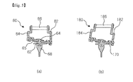
- Figs. 5 (a) and (b) are sectional views showing a coupling structure of a connector of the wiper blade according to the present invention.
- a wiper blade 50 comprises a wiper strip 60 brought into contact with a windshield and a wiper frame 70 coupled with the wiper strip 60.
- the wiper strip 60 is brought into close contact with the windshield to wipe out contaminants on the windshield.
- the wiper frame 70 has elasticity to bring the wiper strip 60 into close contact with the windshield.
- the wiper frame 70 is made of a thin metal sheet with a predetermined elasticity and is formed to be curved in along its lengthwise direction, to press the wiper strip 60.
- a connector 80 is coupled with the wiper frame 70 so as to couple the wiper blade with a wiper arm 15 (Fig. 1) of a vehicle.
- the wiper strip 60 is disposed perpendicularly to the windshield and coupled with the wiper frame 70 to be inclined.
- a coupling section 64 is formed on an upper end of a body portion 62 of the wiper strip 60.
- the coupling section 64 is formed with rail grooves 65 to have both sides opened and to be coupled with the wiper frame 70.
- a strip portion 68 is formed in a lower end of the body portion 62 to be brought into perpendicular contact with the windshield and to wipe the windshield by the operation of the wiper arm.
- the coupling section 64 of the wiper strip 60 is formed to be inclined in one direction with respect to a moving direction of the wiper strip 60, so that the wiper frame 70 to be coupled with the rail grooves 65 is also formed to be inclined.
- the wiper frame 70 will be described with reference to Figs. 6 (a) to (c).
- Coupling slits 75 are formed in the wiper frame 70 to be coupled with the rail grooves 65 of the wiper strip 60.
- Each of the coupling slits 75 is formed to extend in the lengthwise direction and has a predetermined width such that the rail grooves 65 of the wiper strip 60 can be fitted therein.
- a plurality of coupling slits 75 may be intermittently and sequentially formed and disposed.
- the wiper strip 60 is formed such that the coupling section 64 corresponds to the coupling slits 75 of the wiper frame 70. That is, the coupling section 64 of the wiper strip 60 comprises a cut-out portion 69 formed by cutting out a portion corresponding to the portion in which the coupling slit 75 is not formed.
- Figs. 6 (a) to (c) show examples in which two coupling slits 75 are formed
- one coupling slit 75 may be formed as shown in Fig. 6 (d).
- the wiper strip can be coupled with the coupling slit at one time by inserting the wiper strip into a coupling aperture 74 of the coupling slit 75 to fit the wiper strip into the coupling slit and then by sliding the wiper strip in one side.
- the coupling aperture 74 which can receive a portion of the coupling section 64 of the wiper strip 60, is formed in one end of the coupling slit 75 in order to insert the coupling section 64 of the wiper strip 60 thereinto.
- An end of the coupling aperture 74 connected to the coupling slit 75 is formed to be inclined in the fitting direction of the wiper strip 60, and thus the rail grooves 65 of the wiper strip 60 can be easily fitted to the coupling slit 75.
- an auxiliary coupling slit 78 is formed in the wiper frame 70 to be connected to the other end of the coupling aperture 74.
- the auxiliary coupling slit 78 is formed collinearly with the coupling slit 75 and fitted to the rail grooves 65 formed in the rear end of the wiper strip 60.
- the front end of the wiper strip 60 is fitted to the coupling slits 75 via the coupling aperture 74, and then, the front end of the wiper strip 60 is elastically deformed and inserted into the coupling aperture 74 by compressing the rear end of the wire strip 60.
- the rail grooves 65 formed at the rear end of the wiper strip 60 is fitted to the auxiliary coupling slit 78.
- the wiper frame 70 may be formed with an inclined portion 71 at the end in which the coupling aperture 74 is formed, by bending the end in order for the coupling aperture 74 to be opened slantingly at a predetermined angle, as shown in Figs. 7 (a) and (b).
- the most preferable inclination angle of the inclined portion 71 is in a range of 5 to 35 degrees, but is necessarily limited thereto.
- the coupling aperture 74 is formed to be inclined, the coupling section 64 of the wiper strip 60 can be easily inserted into the coupling aperture 74 when the wiper strip 60 is assembled.
- the wiper frame 70 may be formed with recesses corresponding to each other on both sides of the coupling slit 75.
- the wiper strip 60 is formed with protrusions 66 which are placed in recesses when the wiper strip is coupled with the coupling slit 75.
- the wiper strip 60 and the protrusions 66 are made of a material having a predetermined elasticity. Accordingly, the protrusion 66 is compressed when the wiper strip is coupled with the coupling slit 75 and is restored when the protrusion is placed in the recesses, so that the coupling force between the wiper strip 60 and the wiper frame 70 is increased.
- the front and rear portions of the wiper frame 70 with respect to the coupling slit 75 may be symmetric in width (see Fig. 6 (a)).
- the wiper frame 70 may be formed such that the front portion of the wiper frame 70 with respect to the coupling slit 75 is larger than the rear portion (see Fig. 6 (b)).
- the wiper frame 70 may be formed to have a portion larger than the other portion, the wiper frame is more influenced by the wind when a vehicle is driven, and the wiper frame is pressed by the wind as the vehicle is driven at a high speed, so that the wiper frame 70 is brought into more close contact with the windshield.
- the wiper frame 70 may be formed to have the rear portion with respect to the coupling slit 75 larger than the front portion, as shown in Fig. 6 (c).
- the connector 80 has an inclined coupling structure for coupling the wiper frame 70, which is arranged to be inclined with respect to the wiper strip 60, to the wiper arm.
- the connector 80 includes a connecting rod portion in which a connecting rod 86 connected to the wiper arm is located and an assembling portion which is assembled to the wiper frame 70.
- the inclined coupling structure as described above may be configured such that a lower surface of the connector in contact with the wiper frame is formed to be inclined by causing the lengths of the front and rear portions of the assembling portion to differ from each other as shown in Fig. 5 (a), or such that the connecting rod 186 is mounted to be inclined by causing the lengths of the front and rear portions of the connecting rod portion to differ from each other as shown in Fig. 5 (b).
- a coupling structure appropriate to a coupling method is provided in a lower portion of the connector 80.
- a variety of methods may be used, such as a method by curling, a securing method with rivets, or a bonding method with welding or adhesive. Examples of the methods are shown in Figs. 10 (b) to (d).
- two or more coupling methods can be used simultaneously.
- Fig. 10 (b) shows the method for coupling the connector 80 to the wiper frame 70 in which there are provided four protrusions 83 extending from both ends of the lower portion of the connector 80 and the protrusions 83 are curled to enclose the wiper frame.
- protrusions are formed on both sides of the center of the lower portion of the connector 80, guides to which the wiper frame is fitted are respectively formed in both ends of the lower portion of the connector 80, and only the protrusions formed in both the sides of the center are curled, so that the connector 80 is combined with the wiper frame 70 and the guides formed in both the ends guide the wiper frame not to be shaken when and/or after the connector is coupled to the wiper frame.
- the protrusions for coupling the connector 80 to the wiper frame 70 may be formed on the wiper frame 70.
- Fig. 10 (c) shows an example in which the connector 80 is coupled to the wiper frame 70 with rivets
- Fig. 10 (d) shows an example in which the connector 80 is coupled to the wiper frame 70 by welding or adhesive.
- a fixing protrusion may be further formed on any one of the contact surfaces between the connector 80 and the wiper frame 70 and a fixing hole coupled to the fixing protrusion may be further formed in the other of the contact surfaces.
- fixing protrusions 79 are formed on a surface of the wiper frame 40 in contact with the connector 70, and fixing holes 89 coupled with the fixing protrusions 79 are formed in a lower surface of the connector 80.
- the fixing protrusions 79 are fitted into the fixing holes 89 in advance and their relative positions are fixed, so that their positions are prevented from being changed in the process of coupling the connector 80 to the wiper frame 70. That is, the fixing protrusions 79 and the fixing holes 89 shown in Fig. 10 (a) can be further applied to the coupling methods shown in Figs. 10 (b) to (d). In addition, the coupling reliability can be more securely improved by welding the fixing protrusions 79 and the fixing holes 89 to each other. For example, the fixing holes 89 and the fixing protrusions 79 shown in Fig.
- the fixing hole 89 is formed to be penetrated in the embodiment of the present invention, the fixing hole need not be penetrated but any hole to be coupled with the fixing protrusion 79 may be employed. Also, the fixing hole 89 and the fixing protrusion 79 may be formed in a variety of shapes such as a circle, a quadrangle and the like, and at least one or more of the fixing holes and the fixing protrusions can be formed. In addition, when the fixing hole 89 is formed in a rectangular shape or a plurality of fixing holes are provided, it is possible to prevent the connector 80 from being rotated.
- a lower surface of the connector 80 may be curved with the same curvature as that of the wiper frame 70 in order to prevent a curvature of the wiper frame 70 from being changed when the connector is coupled with wiper frame.
- the curvature of the lower surface of the connector 80 is preferably in a range between 600 and 900R.
- a reinforcement structure is applied in order to solve the problem that the strength of the wiper frame 270 is lowered, which can be caused by forming only one coupling slit 275.
- Figs. 11 (a) to (c) are a plane view showing a wiper frame of the wiper frame of the other embodiment according to the present invention, a sectional view thereof, and a sectional view showing that a wiper strip is coupled with the wiper frame, respectively.
- At least one through portion 276 connected to a coupling slit 275 is formed in a wiper frame 270.
- an arch-shaped rib 278 is formed on the front and rear sides of the wiper frame 270 with respect to the coupling slit 275 to span the coupling slit 275 and to connect both the sides of the wiper frame 270.
- a size of the through portion 276 corresponds to a width of the coupling section 64 of the wiper strip 60, so that the through portion does not interfere with the coupling section 64 when the wiper strip 60 is coupled.
- Fig. 12 is a plane view showing a wiper frame of a wiper blade of a further embodiment according to the present invention
- Figs. 13 (a) to (c) are respectively sectional views of Fig. 12 and its modifications showing that the wiper strip is coupled.
- the wiper blade according to the further embodiment of the present invention comprises brought into contact with a windshield, a wiper frame 370 coupled with the wiper strip 360 and curved along its lengthwise direction to provide an elastic force for bring the wiper strip 360 into close contact with the windshield, and a connector (not shown) coupled with the wiper frame to be coupled with the wiper arm.
- the technical configuration of the connector applied to the further embodiment of the present invention and the coupling method of the connector and the wiper frame are the same as those of the first embodiment of the present invention.
- a spoiler 372 is formed on the wiper frame 370 to increase an area exposed to wind.
- the wiper frame 370 is formed with a bending slit 373 for bending the spoiler 372.
- the spoiler 372 may be an upper spoiler 372a integrally formed on a rear surface of the wiper frame 70 as shown in Fig. 13 (a), or a lower spoiler 372b integrally formed on a front surface of the wiper frame 70 as shown in Fig. 13 (b).
- the upper and lower spoilers 372a and 372b may be integrally formed on a front and rear surfaces of the wiper frame 70.
Abstract
Description
- The present invention relates to a wiper blade mounted to a wiper apparatus for a vehicle to wipe a windshield, and more particularly, to a wiper blade having an improved coupling structure of a connector for coupling a wiper frame to a wiper arm.
- Fig. 1 is a perspective view of a vehicle to which a conventional wiper blade is mounted, and Fig. 2 is a front view of the conventional wiper blade.
- As shown in Fig. 1 and Fig. 2, the conventional wiper apparatus comprises a
wiper arm 15 installed at one side of avehicle body 10 and rotated from side to side by a wiper motor (not shown), and awiper blade 20 mounted to thewiper arm 15, moved on and contacted with awindshield 12 to wipe it, and provided with awiper strip 30. - The
wiper blade 20 is coupled with thewiper arm 15 and is rotated within a predetermined angle range according to operation of the wiper motor. To this end, amain link 22 of thewiper blade 20 is coupled with thewiper arm 15. A plurality ofintermediate links 24 are connected to themain link 22 throughpins 25 for uniformly transmitting pressure of thewiper arm 15 to themain link 22. A plurality ofsub links 26 are connected to theintermediate links 24 withpins 27 to connect theintermediate links 24 to thewiper strip 30. Also,clips 28 are formed at both ends of thesub link 26 and coupled with coupling grooves formed in thewiper strip 30. - Further, the
wiper blade 20 is provided with ajoint 29 to reduce a friction force between themain link 22 and theintermediate links 24. - In the wiper blade according to the prior art, however, a process of assembling a wiper strip as well as a structure for securing it are complicated, whereby there is a problem in that a time required for assembling the wiper blade is increased to lower a productivity of the articles. Also, in the conventional wiper blade, since the links are moved relative to each other when the wiper blade is operated, noises can be generated in the operation of the wiper blade. In addition, in the conventional wiper blade, the wiper blade is lifted up from the windshield by the wind when the vehicle is driven at a high speed, which causes a contacting force between the wiper blade and the windshield to be lowered. Accordingly, in order to solve the above problem, the structure in which an additional windbreak rib is provided on the main link has been proposed. However, a complete solution has not been proposed, so that there is a room for improvement of the wiper blade.
- The present invention is conceived to solve the aforementioned problems in the prior art. An object of the present invention is to provide a wiper blade, which has a wiper frame formed to have elasticity, thereby being simple in structure, and has a connector, which is to be coupled with a wiper arm and is more accurately and securely coupled with the wiper frame.
- According to the present invention for achieving the above object, there is provided a wiper blade according to the present invention comprises a wiper strip in contact with the windshield, the wiper strip having a rail groove formed; a wiper frame having a coupling slit to be coupled with the rail groove and a coupling aperture formed in an end of the coupling slit, the wiper frame being curved along its lengthwise direction to provide an elastic force for bring the wiper strip into close contact with the windshield; and a connector to be coupled with the wiper frame and coupled to a wiper arm, wherein the wiper strip is arranged perpendicular to the windshield and coupled with the wiper frame to be inclined with respect thereto, and the connector has an inclined coupling structure for coupling the wiper frame to the wiper arm.
- Here, a connecting rod is mounted to be inclined by causing the lengths of front and rear portions of a connecting rod portion to differ from each other, or a lower surface of the connector in contact with the wiper frame is formed to be inclined by causing the lengths of the front and rear portions of the assembling portion to differ from each other, so that the inclined coupling structure may be configured. In addition, the wiper frame may have an inclined portion formed in an end thereof in which the coupling aperture is formed, the coupling aperture being bent to be opened slantingly at a predetermined angle. In the meantime, the wiper strip may comprise a body portion, a coupling section formed on an upper end of the body portion and having a rail groove provided therein, and a strip portion formed in a lower end of the body portion to be brought into contact with the windshield, and the strip portion has a portion corresponding to the end inclined portion of the wiper frame removed. Further, the wiper frame may be formed with at least one coupling slit having a coupling aperture formed in one end thereof, and the wiper strip may be formed corresponding to the coupling slit. In addition, recesses may be formed in both sides of the coupling slit, and the wiper strip may also comprise protrusions positioned in the recesses when the wiper strip is coupled with the wiper frame. Also, the wiper frame may comprise a through portion formed in front and rear sides with respect to the coupling slit and connected with the coupling slit, and an arch-shaped rib formed over the through portion and connecting both the sides of the wiper frame. In addition, the wiper frame may comprise an auxiliary coupling slit connected with the coupling aperture and is formed collinearly with the coupling slit. Further, front and rear portions of the wiper frame with respect to the coupling slit may be symmetric in shape, or any one of the front and rear portions with respect to the coupling slit may be larger than the other one. Furthermore, the connector may be coupled to the wiper frame by any one of curling, riveting, welding or bonding with adhesive. A fixing protrusion may be formed on any one of the contact surfaces between the connector and the wiper frame, and a fixing hole corresponding to the fixing protrusion may be formed in the other one. The connector may have a lower surface curved with the same curvature as that of the wiper frame.
- According to another embodiment of the present invention for achieving the above object, there is provided a wiper blade, comprising a wiper strip in contact with a windshield; a wiper frame coupled with the wiper strip and curved along its lengthwise direction to provide an elastic force for bring the wiper strip into close contact with the windshield; and a connector coupled with the wiper frame to be coupled to a wiper arm, wherein a spoiler is integrally formed on the wiper frame to be inclined at a predetermined angle.
- The wiper frame may comprise a bending slit for bending the spoiler. Also, the wiper frame may comprise at least one or both of an upper spoiler formed on a rear surface of the wiper frame to be inclined upward and a lower spoiler formed on a front surface of the wiper frame to be inclined downward.
- According to a wiper blade of the present invention configured as above, there are advantages in that a structure of a wiper frame for securing a wiper strip is simple, a process of assembling the wiper strip to the wiper frame is simple, a time required for the assembling process can be reduced, and the manufacturing costs can be remarkably reduced and the durability of the article can be significantly improved since the wiper frame is formed to have predetermined elasticity and therefore no additional part is necessary. There is also an advantage in that the wiper frame and the connector are securely coupled with each other, whereby the position change or rotation therebetween cannot occur.
- Fig. 1 is a perspective view of a vehicle to which a conventional wiper blade is mounted;
- Fig. 2 is a front view of the conventional wiper blade;
- Fig. 3 is a perspective view of a wiper blade according to the present invention;
- Fig. 4 is an exploded perspective view of the wiper blade according to the present invention;
- Figs. 5 (a) and (b) are sectional views showing a coupling structure of a connector of the wiper blade according to the present invention;
- Figs. 6 (a) to (d) are plane views showing a wiper frame of the wiper blade according to the present invention;
- Figs. 7 (a) and (b) are a front view and an enlarged sectional view showing that an inclined portion is formed in an end of the wiper frame according to the present invention, respectively;
- Figs. 8 (a) and (b) are a front view and an enlarged sectional view showing that the wiper strip is coupled with the wiper frame according to the present invention shown in Fig. 7, respectively;
- Fig. 9 is a perspective view for showing one example of the coupling slit of the wiper frame according to the present invention, wherein the wiper strip is partially cut away;
- Figs. 10 (a) to (d) are a sectional view and a bottom view illustrating a method for coupling the connector to the wiper frame of the wiper blade according to the present invention, respectively;
- Figs. 11 (a) to (c) are a plane view showing a wiper frame of another embodiment according to the present invention, a sectional view thereof, and a sectional view showing that a wiper strip is coupled with the wiper frame, respectively;
- Fig. 12 is a plane view showing a wiper frame of a further embodiment according to the present invention;
- Figs. 13 (a) to (c) are sectional views of Fig. 12 and its modifications showing that the wiper strip is coupled, respectively; and
- Fig. 14 is a front view of the connector of the wiper blade according to the present invention.
-
- 50:
- Wiper Blade
- 62:
- Body portion
- 65:
- Rail Groove
- 68:
- Strip portion
- 70:
- Wiper Frame
- 73:
- Protrusion
- 75:
- Coupling Slit
- 78:
- Auxiliary Coupling Slit
- 80:
- Connector
- 83a:
- Hanging Groove
- 86:
- Connecting Rod
- 60:
- Wiper Strip
- 64:
- Coupling Section
- 66:
- Block Portion
- 69:
- Cut-out portion
- 71:
- Inclined portion
- 74:
- Coupling Aperture
- 76:
- Recess
- 79:
- Fixing Protrusion
- 83:
- Hanging Section
- 83b:
- Bending Section
- 89:
- Fixing Groove
- Hereinafter, embodiments of the present invention will be described in more detail with reference to accompanying drawings.
- Fig. 3 is a perspective view of a wiper blade according to the present invention, Fig. 4 is an exploded perspective view of the wiper blade according to the present invention, and Figs. 5 (a) and (b) are sectional views showing a coupling structure of a connector of the wiper blade according to the present invention.
- As shown in Fig. 3 to 5, a
wiper blade 50 according to the present invention comprises awiper strip 60 brought into contact with a windshield and awiper frame 70 coupled with thewiper strip 60. Thewiper strip 60 is brought into close contact with the windshield to wipe out contaminants on the windshield. In the meantime, thewiper frame 70 has elasticity to bring thewiper strip 60 into close contact with the windshield. In the embodiment of the present invention, thewiper frame 70 is made of a thin metal sheet with a predetermined elasticity and is formed to be curved in along its lengthwise direction, to press thewiper strip 60. Also, in thewiper blade 50, aconnector 80 is coupled with thewiper frame 70 so as to couple the wiper blade with a wiper arm 15 (Fig. 1) of a vehicle. - Firstly, the
wiper strip 60 will be described. Thewiper strip 60 is disposed perpendicularly to the windshield and coupled with thewiper frame 70 to be inclined. To this end, acoupling section 64 is formed on an upper end of abody portion 62 of thewiper strip 60. Also, thecoupling section 64 is formed withrail grooves 65 to have both sides opened and to be coupled with thewiper frame 70. In addition, astrip portion 68 is formed in a lower end of thebody portion 62 to be brought into perpendicular contact with the windshield and to wipe the windshield by the operation of the wiper arm. Thecoupling section 64 of thewiper strip 60 is formed to be inclined in one direction with respect to a moving direction of thewiper strip 60, so that thewiper frame 70 to be coupled with therail grooves 65 is also formed to be inclined. Next, thewiper frame 70 will be described with reference to Figs. 6 (a) to (c). Coupling slits 75 are formed in thewiper frame 70 to be coupled with therail grooves 65 of thewiper strip 60. Each of the coupling slits 75 is formed to extend in the lengthwise direction and has a predetermined width such that therail grooves 65 of thewiper strip 60 can be fitted therein. In order to maintain the rigidity of thewiper frame 70 and make it easy to couple thewiper strip 60 thereto, a plurality of coupling slits 75 may be intermittently and sequentially formed and disposed. Thewiper strip 60 is formed such that thecoupling section 64 corresponds to the coupling slits 75 of thewiper frame 70. That is, thecoupling section 64 of thewiper strip 60 comprises a cut-outportion 69 formed by cutting out a portion corresponding to the portion in which the coupling slit 75 is not formed. - Although Figs. 6 (a) to (c) show examples in which two
coupling slits 75 are formed, one coupling slit 75 may be formed as shown in Fig. 6 (d). Also, in a case where the single coupling slit 75 is formed as described above, the wiper strip can be coupled with the coupling slit at one time by inserting the wiper strip into acoupling aperture 74 of the coupling slit 75 to fit the wiper strip into the coupling slit and then by sliding the wiper strip in one side. - Also, the
coupling aperture 74, which can receive a portion of thecoupling section 64 of thewiper strip 60, is formed in one end of the coupling slit 75 in order to insert thecoupling section 64 of thewiper strip 60 thereinto. An end of thecoupling aperture 74 connected to the coupling slit 75 is formed to be inclined in the fitting direction of thewiper strip 60, and thus therail grooves 65 of thewiper strip 60 can be easily fitted to the coupling slit 75. - Also, an auxiliary coupling slit 78 is formed in the
wiper frame 70 to be connected to the other end of thecoupling aperture 74. The auxiliary coupling slit 78 is formed collinearly with the coupling slit 75 and fitted to therail grooves 65 formed in the rear end of thewiper strip 60. To this end, the front end of thewiper strip 60 is fitted to the coupling slits 75 via thecoupling aperture 74, and then, the front end of thewiper strip 60 is elastically deformed and inserted into thecoupling aperture 74 by compressing the rear end of thewire strip 60. At this time, once the compression force exerted on thewiper strip 60 is removed, therail grooves 65 formed at the rear end of thewiper strip 60 is fitted to the auxiliary coupling slit 78. - In the meantime, the
wiper frame 70 may be formed with aninclined portion 71 at the end in which thecoupling aperture 74 is formed, by bending the end in order for thecoupling aperture 74 to be opened slantingly at a predetermined angle, as shown in Figs. 7 (a) and (b). The most preferable inclination angle of theinclined portion 71 is in a range of 5 to 35 degrees, but is necessarily limited thereto. As described above, since thecoupling aperture 74 is formed to be inclined, thecoupling section 64 of thewiper strip 60 can be easily inserted into thecoupling aperture 74 when thewiper strip 60 is assembled. At this time, in order to prevent thestrip portion 68 from being bent when thewiper strip 60 is coupled to thewiper frame 70, a portion A corresponding to theinclined portion 71 is removed. A state where the wiper strip is coupled to thewiper frame 70 having theinclined portion 71 formed in the end thereof is shown in Figs. 8 (a) and (b). - Also, as shown in Fig. 9, the
wiper frame 70 may be formed with recesses corresponding to each other on both sides of the coupling slit 75. Thewiper strip 60 is formed withprotrusions 66 which are placed in recesses when the wiper strip is coupled with the coupling slit 75. Thewiper strip 60 and theprotrusions 66 are made of a material having a predetermined elasticity. Accordingly, theprotrusion 66 is compressed when the wiper strip is coupled with the coupling slit 75 and is restored when the protrusion is placed in the recesses, so that the coupling force between thewiper strip 60 and thewiper frame 70 is increased. - In the shape of the
wiper frame 70, the front and rear portions of thewiper frame 70 with respect to the coupling slit 75 may be symmetric in width (see Fig. 6 (a)). Also, thewiper frame 70 may be formed such that the front portion of thewiper frame 70 with respect to the coupling slit 75 is larger than the rear portion (see Fig. 6 (b)). As described above, if thewiper frame 70 is formed to have a portion larger than the other portion, the wiper frame is more influenced by the wind when a vehicle is driven, and the wiper frame is pressed by the wind as the vehicle is driven at a high speed, so that thewiper frame 70 is brought into more close contact with the windshield. Also, thewiper frame 70 may be formed to have the rear portion with respect to the coupling slit 75 larger than the front portion, as shown in Fig. 6 (c). - Next, the
connector 80 will be described with reference to Figs. 5 (a) and (b). Theconnector 80 has an inclined coupling structure for coupling thewiper frame 70, which is arranged to be inclined with respect to thewiper strip 60, to the wiper arm. To this end, theconnector 80 includes a connecting rod portion in which a connectingrod 86 connected to the wiper arm is located and an assembling portion which is assembled to thewiper frame 70. Also, the inclined coupling structure as described above may be configured such that a lower surface of the connector in contact with the wiper frame is formed to be inclined by causing the lengths of the front and rear portions of the assembling portion to differ from each other as shown in Fig. 5 (a), or such that the connectingrod 186 is mounted to be inclined by causing the lengths of the front and rear portions of the connecting rod portion to differ from each other as shown in Fig. 5 (b). - Also, in order for the
connector 80 to be easily coupled with thewiper frame 70, a coupling structure appropriate to a coupling method is provided in a lower portion of theconnector 80. - Next, a method for coupling the
connector 80 to thewiper frame 70 will be described with reference to Figs. 10 (a) to (d). - As the method for coupling the
connector 80 to thewiper frame 70, a variety of methods may be used, such as a method by curling, a securing method with rivets, or a bonding method with welding or adhesive. Examples of the methods are shown in Figs. 10 (b) to (d). In addition, in order to couple theconnector 80 to thewiper frame 70, two or more coupling methods can be used simultaneously. - That is, Fig. 10 (b) shows the method for coupling the
connector 80 to thewiper frame 70 in which there are provided fourprotrusions 83 extending from both ends of the lower portion of theconnector 80 and theprotrusions 83 are curled to enclose the wiper frame. In addition, as one of cases where the curling methods are used, protrusions are formed on both sides of the center of the lower portion of theconnector 80, guides to which the wiper frame is fitted are respectively formed in both ends of the lower portion of theconnector 80, and only the protrusions formed in both the sides of the center are curled, so that theconnector 80 is combined with thewiper frame 70 and the guides formed in both the ends guide the wiper frame not to be shaken when and/or after the connector is coupled to the wiper frame. On the other hand, the protrusions for coupling theconnector 80 to thewiper frame 70 may be formed on thewiper frame 70. Fig. 10 (c) shows an example in which theconnector 80 is coupled to thewiper frame 70 with rivets, and Fig. 10 (d) shows an example in which theconnector 80 is coupled to thewiper frame 70 by welding or adhesive. - Further, when using the methods for coupling the
connector 80 to thewiper frame 70, a fixing protrusion may be further formed on any one of the contact surfaces between theconnector 80 and thewiper frame 70 and a fixing hole coupled to the fixing protrusion may be further formed in the other of the contact surfaces. Referring to Fig. 10 (a), fixingprotrusions 79 are formed on a surface of the wiper frame 40 in contact with theconnector 70, and fixingholes 89 coupled with the fixingprotrusions 79 are formed in a lower surface of theconnector 80. Accordingly, when theconnector 80 is coupled with thewiper frame 70, the fixingprotrusions 79 are fitted into the fixing holes 89 in advance and their relative positions are fixed, so that their positions are prevented from being changed in the process of coupling theconnector 80 to thewiper frame 70. That is, the fixingprotrusions 79 and the fixing holes 89 shown in Fig. 10 (a) can be further applied to the coupling methods shown in Figs. 10 (b) to (d). In addition, the coupling reliability can be more securely improved by welding the fixingprotrusions 79 and the fixing holes 89 to each other. For example, the fixing holes 89 and the fixingprotrusions 79 shown in Fig. 10 (a) are further applied when using the method for coupling theconnector 80 to thewiper frame 70 with rivets as shown in Fig. 10 (c), the fixing holes 89 and the fixingprotrusions 79 fitted in the fixing holes 89 are bonded to each other by a welding in addition to the riveting of theconnector 80 and thewiper frame 70, so that theconnector 80 and thewiper frame 70 can be more securely coupled with each other to prevent them from being shaken. - Although the fixing
hole 89 is formed to be penetrated in the embodiment of the present invention, the fixing hole need not be penetrated but any hole to be coupled with the fixingprotrusion 79 may be employed. Also, the fixinghole 89 and the fixingprotrusion 79 may be formed in a variety of shapes such as a circle, a quadrangle and the like, and at least one or more of the fixing holes and the fixing protrusions can be formed. In addition, when the fixinghole 89 is formed in a rectangular shape or a plurality of fixing holes are provided, it is possible to prevent theconnector 80 from being rotated. - In addition, as shown in Fig. 14, a lower surface of the
connector 80 may be curved with the same curvature as that of thewiper frame 70 in order to prevent a curvature of thewiper frame 70 from being changed when the connector is coupled with wiper frame. At this time, the curvature of the lower surface of theconnector 80 is preferably in a range between 600 and 900R. - Next, another embodiment of the
wiper frame 70 of the present invention will be described with reference to Fig. 11. - According to the other embodiment of the
wiper frame 70 of the present invention, a reinforcement structure is applied in order to solve the problem that the strength of thewiper frame 270 is lowered, which can be caused by forming only onecoupling slit 275. - Figs. 11 (a) to (c) are a plane view showing a wiper frame of the wiper frame of the other embodiment according to the present invention, a sectional view thereof, and a sectional view showing that a wiper strip is coupled with the wiper frame, respectively.
- As shown in Fig. 11, at least one through
portion 276 connected to acoupling slit 275 is formed in awiper frame 270. Also, an arch-shapedrib 278 is formed on the front and rear sides of thewiper frame 270 with respect to the coupling slit 275 to span the coupling slit 275 and to connect both the sides of thewiper frame 270. A size of the throughportion 276 corresponds to a width of thecoupling section 64 of thewiper strip 60, so that the through portion does not interfere with thecoupling section 64 when thewiper strip 60 is coupled. - Fig. 12 is a plane view showing a wiper frame of a wiper blade of a further embodiment according to the present invention, and Figs. 13 (a) to (c) are respectively sectional views of Fig. 12 and its modifications showing that the wiper strip is coupled.
- As shown in Fig. 12 and 13, the wiper blade according to the further embodiment of the present invention comprises brought into contact with a windshield, a
wiper frame 370 coupled with thewiper strip 360 and curved along its lengthwise direction to provide an elastic force for bring thewiper strip 360 into close contact with the windshield, and a connector (not shown) coupled with the wiper frame to be coupled with the wiper arm. The technical configuration of the connector applied to the further embodiment of the present invention and the coupling method of the connector and the wiper frame are the same as those of the first embodiment of the present invention. In addition, aspoiler 372 is formed on thewiper frame 370 to increase an area exposed to wind. Further, thewiper frame 370 is formed with a bendingslit 373 for bending thespoiler 372. - In the meantime, the
spoiler 372 may be anupper spoiler 372a integrally formed on a rear surface of thewiper frame 70 as shown in Fig. 13 (a), or alower spoiler 372b integrally formed on a front surface of thewiper frame 70 as shown in Fig. 13 (b). Alternatively, as shown in Fig. 13 (c), the upper andlower spoilers wiper frame 70.
Claims (19)
- A wiper blade (50), comprisinga wiper strip (60) in contact with the windshield, the wiper strip having a rail groove (65) formed;a wiper frame (70) having a coupling slit (75) to be coupled with the rail groove and a coupling aperture (74) formed in an end of the coupling slit, the wiper frame being curved along its lengthwise direction to provide an elastic force for bring the wiper strip into close contact with the windshield; anda connector (80) to be coupled with the wiper frame,wherein the wiper strip is coupled with the wiper frame to be inclined with respect thereto.
- The wiper blade (50) according to Claim 1, wherein the connector (80) has an inclined coupling structure in which lengths of front and rear portions of a connecting rod (86) portion differ from each other or lengths of front and rear portions of an assembling portion differ from each other to couple the wiper strip (60) to a wiper arm (15) perpendicularly to the windshield.
- The wiper blade (50) according to Claim 1 or 2, wherein the wiper frame (70) is formed with a coupling slit (75), or two or more coupling slits intermittently and sequentially formed, each coupling slit having a coupling aperture (74) formed in one end thereof.
- The wiper blade according to Claim 1 or 2, wherein the wiper frame (70) has an inclined portion (71) formed in an end thereof in which the coupling aperture is formed, the coupling aperture (74) being bent to be opened slantingly at a predetermined angle.
- The wiper blade according to Claim 4, wherein the inclined portion (71) formed at an end of the wiper frame (70) has an inclination angle in a range of 5 to 35 degrees.
- The wiper blade according to Claim 4, wherein the wiper strip (60) comprises a body portion (62), a coupling section (64) formed on an upper end of the body portion and having a rail groove (65) provided therein, and a strip portion (68) formed in a lower end of the body portion to be brought into contact with the windshield, and the strip portion has a portion corresponding to the inclined portion (71) of the wiper frame removed.
- The wiper blade according to anyone of claims 1 to 6, wherein the wiper frame (70) comprises recesses formed in both sides of the coupling slit (75), and the wiper strip (60) comprises protrusions (66) corresponding to the recesses when the wiper strip is coupled with the wiper frame.
- The wiper blade according to anyone of claims 1 to 7, wherein the wiper frame comprises a through portion formed in front and rear sides with respect to the coupling slit and connected with the coupling slit (75), and an arch-shaped rib (278) formed over the through portion and connecting both the sides of the wiper frame.
- The wiper blade according to anyone of claims 1 to 8, wherein the wiper strip is formed corresponding to the coupling slit.
- The wiper blade according to anyone of claims 1 to 9, wherein the wiper frame comprises an auxiliary coupling slit (78) connected with the coupling aperture (74) and is formed collinearly with the coupling slit.
- The wiper blade according to anyone of claims 1 to 10, wherein front and rear portions of the wiper frame with respect to the coupling slit is symmetric in shape, or any one of the front and rear portions with respect to the coupling slit (75) is larger than the other one.
- The wiper blade according to anyone of claims 1 to 11, wherein the connector (80) is coupled to the wiper frame by any one of curling, riveting, welding or adhesion.
- The wiper blade according to anyone of claims 1 to 12, wherein protrusions (83) are formed on both sides of the center of a lower portion of the connector, guides to which the wiper frame is fitted are respectively formed in both ends of the lower portion of the connector, and only the protrusions formed in both the sides of the center are curled, whereby the connector is combined with the wiper frame and the guides formed in both the ends guide the wiper frame not to be shaken when and/or after the connector is coupled to the wiper frame.
- The wiper blade according to anyone of claims 1 to 13, wherein a fixing protrusion (79) is formed on any one of a lower surface of the connector and an upper surface of the wiper frame which are the contact surfaces between the connector (80) and the wiper frame, and a fixing hole (89) corresponding to the fixing protrusion is formed in the other one.
- The wiper blade according to claim 14, wherein the fixing hole (89) and the fixing protrusion (79) fitted into the fixing hole are bonded to each other by welding when the connector and wiper frame are coupled with each other by curling or riveting.
- The wiper blade according to anyone of claims 1 to 15, wherein the connector (80) has a lower surface curved with the same curvature as that of the wiper frame.
- A wiper blade, comprisinga wiper strip (60) in contact with a windshield;a wiper frame (370) coupled with the wiper strip and curved along its lengthwise direction to provide an elastic force for bring the wiper strip into close contact with the windshield; anda connector (80) coupled with the wiper frame,wherein a spoiler (372) is integrally formed on the wiper frame to be inclined at a predetermined angle.
- The wiper blade according to claim 17, wherein the wiper frame comprises a bending slit (373) for bending the spoiler.
- The wiper blade according to Claim 17 or 18, wherein the wiper frame comprises at least one or both of an upper spoiler (372a) formed on a rear surface of the wiper frame to be inclined upward and a lower spoiler (372b) formed on a front surface of the wiper frame to be inclined downward.
Priority Applications (1)
| Application Number | Priority Date | Filing Date | Title |
|---|---|---|---|
| PL06125454T PL1800978T3 (en) | 2005-12-05 | 2006-12-05 | Wiper blade |
Applications Claiming Priority (1)
| Application Number | Priority Date | Filing Date | Title |
|---|---|---|---|
| KR1020050117621A KR100733623B1 (en) | 2005-12-05 | 2005-12-05 | Wiper blade |
Publications (3)
| Publication Number | Publication Date |
|---|---|
| EP1800978A2 true EP1800978A2 (en) | 2007-06-27 |
| EP1800978A3 EP1800978A3 (en) | 2009-11-11 |
| EP1800978B1 EP1800978B1 (en) | 2011-02-16 |
Family
ID=37776797
Family Applications (1)
| Application Number | Title | Priority Date | Filing Date |
|---|---|---|---|
| EP06125454A Not-in-force EP1800978B1 (en) | 2005-12-05 | 2006-12-05 | Wiper blade |
Country Status (11)
| Country | Link |
|---|---|
| US (1) | US7945986B2 (en) |
| EP (1) | EP1800978B1 (en) |
| JP (1) | JP4938426B2 (en) |
| KR (1) | KR100733623B1 (en) |
| CN (1) | CN1978254B (en) |
| AT (1) | ATE498524T1 (en) |
| CA (1) | CA2569977C (en) |
| DE (1) | DE602006020107D1 (en) |
| ES (1) | ES2361295T3 (en) |
| PL (1) | PL1800978T3 (en) |
| PT (1) | PT1800978E (en) |
Cited By (12)
| Publication number | Priority date | Publication date | Assignee | Title |
|---|---|---|---|---|
| WO2008049686A1 (en) * | 2006-10-27 | 2008-05-02 | Robert Bosch Gmbh | Wiper blade |
| KR101117956B1 (en) * | 2009-10-01 | 2012-03-13 | 주식회사 캐프 | Adapter of vehicle wiper |
| US9889822B2 (en) | 2014-03-07 | 2018-02-13 | Pylon Manufacturing Corp. | Windshield wiper connector and assembly |
| US10005431B2 (en) | 2011-04-21 | 2018-06-26 | Pylon Manufacturing Corp. | Vortex damping wiper blade |
| US10077026B2 (en) | 2012-02-24 | 2018-09-18 | Pylon Manufacturing Corp. | Wiper blade |
| US10166951B2 (en) | 2013-03-15 | 2019-01-01 | Pylon Manufacturing Corp. | Windshield wiper connector |
| US10189445B2 (en) | 2012-02-24 | 2019-01-29 | Pylon Manufacturing Corp. | Wiper blade |
| US10457252B2 (en) | 2011-07-28 | 2019-10-29 | Pylon Manufacturing Corp. | Windshield wiper adapter, connector and assembly |
| US10464533B2 (en) | 2011-04-21 | 2019-11-05 | Pylon Manufacturing Corp. | Wiper blade with cover |
| US10597004B2 (en) | 2011-07-29 | 2020-03-24 | Pylon Manufacturing Corporation | Windshield wiper connector |
| US10829092B2 (en) | 2012-09-24 | 2020-11-10 | Pylon Manufacturing Corp. | Wiper blade with modular mounting base |
| US11040705B2 (en) | 2016-05-19 | 2021-06-22 | Pylon Manufacturing Corp. | Windshield wiper connector |
Families Citing this family (19)
| Publication number | Priority date | Publication date | Assignee | Title |
|---|---|---|---|---|
| KR100960651B1 (en) | 2009-02-12 | 2010-06-07 | (주) 에이피아이코리아 | Windshield wiper assembly |
| US8037568B2 (en) | 2005-09-19 | 2011-10-18 | Alberee Products Inc. | Windshield wiper assembly |
| KR100813643B1 (en) * | 2005-11-30 | 2008-03-14 | 에이디엠이십일 주식회사 | Wiper blade |
| KR100699187B1 (en) * | 2005-11-30 | 2007-03-23 | 에이디엠이십일 주식회사 | Wiper blade |
| US7523522B2 (en) | 2006-09-22 | 2009-04-28 | Federal Mogul World Wide, Inc | Two-piece connector for flat blade windshield wiper |
| KR100808406B1 (en) * | 2007-02-12 | 2008-02-29 | 주식회사 캐프 | Automobile wiper-blade system |
| FR2925001B1 (en) * | 2007-12-18 | 2010-02-12 | Valeo Systemes Dessuyage | WIPER BLADE WITH CONNECTOR AND METHOD OF MANUFACTURING SUCH BRUSH |
| JP5342713B2 (en) * | 2008-09-29 | 2013-11-13 | 株式会社三田 | Winter wiper |
| WO2011031516A2 (en) * | 2009-08-27 | 2011-03-17 | Trico Products Corporation | Windshield wiper assembly |
| DE102010039788A1 (en) * | 2010-08-26 | 2012-03-01 | Robert Bosch Gmbh | Wiper rail element with integrated wiper arm connection |
| DE102010062905A1 (en) * | 2010-12-13 | 2012-06-14 | Robert Bosch Gmbh | Wiper blade device |
| US8806700B2 (en) | 2011-07-29 | 2014-08-19 | Pylon Manufacturing Corporation | Wiper blade connector |
| WO2013090513A1 (en) * | 2011-12-14 | 2013-06-20 | Federal-Mogul Corporation | Windscreen wiper device |
| KR101369629B1 (en) * | 2012-04-06 | 2014-03-04 | 주식회사 캐프 | Wiper device for vehicle |
| US9539987B2 (en) | 2014-04-01 | 2017-01-10 | Trico Products Corporation | Wiper adapter and wiper assembly incorporating the same |
| US9434355B2 (en) | 2014-04-01 | 2016-09-06 | Trico Products Corporation | Wiper adapter and wiper assembly incorporating the same |
| USD777079S1 (en) | 2014-10-03 | 2017-01-24 | Pylon Manufacturing Corp. | Wiper blade frame |
| US20180037196A1 (en) * | 2016-08-04 | 2018-02-08 | Federal-Mogul Motorparts Corporation | Windscreen wiper device |
| CN108297835A (en) * | 2018-02-05 | 2018-07-20 | 丹阳镇威汽配有限公司 | Connector assembly |
Family Cites Families (52)
| Publication number | Priority date | Publication date | Assignee | Title |
|---|---|---|---|---|
| GB838316A (en) * | 1957-04-27 | 1960-06-22 | Renault | Improvements in or relating to windscreen wipers |
| US3035298A (en) | 1958-06-16 | 1962-05-22 | Trico Products Corp | Windshield cleaning system |
| US3060480A (en) * | 1959-07-24 | 1962-10-30 | Gen Motors Corp | Windshield wiper blade |
| US3141186A (en) * | 1961-09-11 | 1964-07-21 | Trico Products Corp | Windshield wiper |
| US3114926A (en) * | 1961-09-25 | 1963-12-24 | Trico Products Corp | Windshield wiper |
| US3132368A (en) | 1962-03-29 | 1964-05-12 | Gen Motors Corp | Windshield wiper blade assembly |
| US3643286A (en) * | 1970-03-18 | 1972-02-22 | Leo J Wubbe | Windshield wiper |
| IT1032660B (en) * | 1975-04-11 | 1979-06-20 | Arman Sas Di Dario Arman Ec | REED SUPPORT FOR WIPER BRUSHES IN WIPER SYSTEMS ON BOARD OF MOTOR VEHICLES IN GENERAL |
| US4075731A (en) | 1975-10-28 | 1978-02-28 | The Anderson Company | Windshield wiper refill unit |
| IT1118510B (en) * | 1979-03-23 | 1986-03-03 | Apman Spa | TERGIORISTALLO SPATULA |
| JPS56116536A (en) * | 1980-02-13 | 1981-09-12 | Nippon Soken Inc | Window shield wiper apparatus |
| US4343063A (en) | 1980-09-29 | 1982-08-10 | Trico Products Corporation | Windshield wiper assembly |
| JPS63182959A (en) * | 1987-01-23 | 1988-07-28 | Matsushita Electric Ind Co Ltd | Photoelectric conversion device |
| DE3903219C2 (en) * | 1989-02-03 | 1999-05-06 | Teves Gmbh Alfred | Wiper blade |
| FR2648771B1 (en) * | 1989-06-22 | 1994-11-10 | Peugeot | WIPER BLADE CLEANING LIQUID DISPENSER |
| GB9000099D0 (en) | 1990-01-03 | 1990-03-07 | Trico Folberth Ltd | Windscreen wiper blade |
| JPH03107550U (en) * | 1990-02-20 | 1991-11-06 | ||
| JPH0911862A (en) * | 1995-07-03 | 1997-01-14 | Fukoku Co Ltd | Wiper blade rubber |
| DE29611721U1 (en) * | 1996-07-05 | 1997-11-06 | Bosch Gmbh Robert | Wiper blade for windows of motor vehicles |
| KR100206157B1 (en) * | 1996-09-05 | 1999-07-01 | 김인규 | A wiper blade with spoiler |
| DE19729864A1 (en) | 1997-07-11 | 1999-01-14 | Bosch Gmbh Robert | Wiper blade for cleaning vehicle windows |
| DE19729865A1 (en) | 1997-07-11 | 1999-01-14 | Bosch Gmbh Robert | Windshield wipers for motor vehicles |
| DE19738232A1 (en) | 1997-09-02 | 1999-03-04 | Bosch Gmbh Robert | Support element for a wiper strip belonging to a wiper blade for windshields of motor vehicles and method for its production |
| DE19739256A1 (en) | 1997-09-08 | 1999-03-11 | Bosch Gmbh Robert | Wiper blade for cleaning windows of motor vehicles |
| ID24119A (en) | 1997-09-25 | 2000-07-06 | Nippon Wiper Blade Co Ltd | TURTLE TOWER WITH WIND BENDERS |
| DE19802451A1 (en) | 1998-01-23 | 1999-07-29 | Bosch Gmbh Robert | Wiper blade for windscreens of motor vehicles |
| ES2221432T3 (en) | 1998-10-12 | 2004-12-16 | Trico Products Corporation | WIPER WASHER. |
| DE19854372A1 (en) * | 1998-11-25 | 2000-05-31 | Bosch Gmbh Robert | Wiper blade for cleaning a vehicle window |
| DE19859077A1 (en) | 1998-12-21 | 2000-06-29 | Bosch Gmbh Robert | windshield wipers |
| US6266843B1 (en) * | 1999-05-03 | 2001-07-31 | Ford Global Technologies,Inc. | Vehicle window wiper assembly having one-piece carrier with flexible tips |
| MXPA01002497A (en) * | 1999-07-09 | 2003-03-12 | Bosch Gmbh Robert | Wiper blade for windshields, especially automobile windshields, and method for the production thereof. |
| DE19945858A1 (en) | 1999-09-24 | 2001-03-29 | Bosch Gmbh Robert | Wiper blades of different dimensions for windows of motor vehicles |
| FR2804393B1 (en) | 2000-01-31 | 2002-05-03 | Valeo Systemes Dessuyage | WIPER SQUEEGEE FOR A WIPER BLADE AND WINDSCREEN WIPER OF A MOTOR VEHICLE EQUIPPED WITH SUCH A SQUEEGEE |
| USD443854S1 (en) | 2000-03-01 | 2001-06-19 | Robert Bosch Gmbh | Windshield wiper |
| DE10011841A1 (en) * | 2000-03-10 | 2001-10-11 | Volkswagen Ag | Wiper blade for a motor vehicle windscreen wiper system comprises an elongated support element having a concave support rail provided with an elongated receiving slit which is closed at both ends and has a wider section at one end |
| US6675433B1 (en) | 2000-07-06 | 2004-01-13 | Trico Products Corporation | Beam blade wiper assembly having improved wind lift characteristics |
| DE10054235A1 (en) | 2000-11-02 | 2002-05-08 | Valeo Auto Electric Gmbh | wiper device |
| DE10107021A1 (en) | 2001-02-15 | 2002-08-22 | Volkswagen Ag | Windscreen wiper comprises spring steel sheet onto which a profile of thermoplastic elastomer is co-extruded |
| DE10112658A1 (en) | 2001-03-16 | 2002-09-19 | Bosch Gmbh Robert | Wiper blade for motor vehicle has mass component in region of upper surface of wiper strip support element facing away from windscreen and which at least in displacement direction of wiper blade can move and especially tilt |
| JP3830801B2 (en) * | 2001-10-23 | 2006-10-11 | アスモ株式会社 | Vehicle wiper device |
| JP3637037B2 (en) * | 2002-06-27 | 2005-04-06 | ピア株式会社 | Wiper blade assembly |
| ES2319738T3 (en) | 2002-09-24 | 2009-05-12 | Federal-Mogul S.A. | A WINDSHIELD CLEANING DEVICE. |
| JP4308602B2 (en) * | 2003-08-08 | 2009-08-05 | 日本ワイパブレード株式会社 | Wiper blade |
| CN2714388Y (en) * | 2004-07-30 | 2005-08-03 | 古淑兰 | Improved structure of windshield wiper |
| DE202004012132U1 (en) | 2004-08-03 | 2004-10-14 | Ku, Shu-Lan, Hsingchuang | Windscreen wiper, assembled of elastic metal strip, rubber lip and two rubber cover elements |
| US20060064840A1 (en) | 2004-09-30 | 2006-03-30 | Se-Heon Park | Automotive wiper |
| US7681277B2 (en) | 2004-11-24 | 2010-03-23 | Se-Heon Park | Automotive wiper |
| KR100662629B1 (en) * | 2005-07-01 | 2007-01-02 | 박세헌 | Rubber blade of wiper for car |
| USD524223S1 (en) | 2005-07-05 | 2006-07-04 | Asmo Co., Ltd. | Wiper blade |
| CA2548939C (en) | 2005-08-26 | 2010-10-05 | Se-Heon Park | Vehicular wiper frame |
| KR100699187B1 (en) | 2005-11-30 | 2007-03-23 | 에이디엠이십일 주식회사 | Wiper blade |
| KR100813643B1 (en) | 2005-11-30 | 2008-03-14 | 에이디엠이십일 주식회사 | Wiper blade |
-
2005
- 2005-12-05 KR KR1020050117621A patent/KR100733623B1/en active IP Right Grant
-
2006
- 2006-11-30 JP JP2006324791A patent/JP4938426B2/en not_active Expired - Fee Related
- 2006-11-30 US US11/565,527 patent/US7945986B2/en not_active Expired - Fee Related
- 2006-12-04 CA CA2569977A patent/CA2569977C/en not_active Expired - Fee Related
- 2006-12-05 ES ES06125454T patent/ES2361295T3/en active Active
- 2006-12-05 CN CN2006101618825A patent/CN1978254B/en not_active Expired - Fee Related
- 2006-12-05 PL PL06125454T patent/PL1800978T3/en unknown
- 2006-12-05 EP EP06125454A patent/EP1800978B1/en not_active Not-in-force
- 2006-12-05 DE DE602006020107T patent/DE602006020107D1/en active Active
- 2006-12-05 PT PT06125454T patent/PT1800978E/en unknown
- 2006-12-05 AT AT06125454T patent/ATE498524T1/en active
Non-Patent Citations (1)
| Title |
|---|
| None |
Cited By (16)
| Publication number | Priority date | Publication date | Assignee | Title |
|---|---|---|---|---|
| WO2008049686A1 (en) * | 2006-10-27 | 2008-05-02 | Robert Bosch Gmbh | Wiper blade |
| KR101117956B1 (en) * | 2009-10-01 | 2012-03-13 | 주식회사 캐프 | Adapter of vehicle wiper |
| US10543813B2 (en) | 2010-02-10 | 2020-01-28 | Pylon Manufacturing Corp. | Wiper blade |
| US10464533B2 (en) | 2011-04-21 | 2019-11-05 | Pylon Manufacturing Corp. | Wiper blade with cover |
| US11124158B2 (en) | 2011-04-21 | 2021-09-21 | Pylon Manufacturing Corp. | Wiper blade with cover |
| US10005431B2 (en) | 2011-04-21 | 2018-06-26 | Pylon Manufacturing Corp. | Vortex damping wiper blade |
| US10457252B2 (en) | 2011-07-28 | 2019-10-29 | Pylon Manufacturing Corp. | Windshield wiper adapter, connector and assembly |
| US10597004B2 (en) | 2011-07-29 | 2020-03-24 | Pylon Manufacturing Corporation | Windshield wiper connector |
| US10077026B2 (en) | 2012-02-24 | 2018-09-18 | Pylon Manufacturing Corp. | Wiper blade |
| US10189445B2 (en) | 2012-02-24 | 2019-01-29 | Pylon Manufacturing Corp. | Wiper blade |
| US11136002B2 (en) | 2012-02-24 | 2021-10-05 | Pylon Manufacturing Corp. | Wiper blade |
| US11180118B2 (en) | 2012-02-24 | 2021-11-23 | Pylon Manufacturing Corp. | Wiper blade |
| US10829092B2 (en) | 2012-09-24 | 2020-11-10 | Pylon Manufacturing Corp. | Wiper blade with modular mounting base |
| US10166951B2 (en) | 2013-03-15 | 2019-01-01 | Pylon Manufacturing Corp. | Windshield wiper connector |
| US9889822B2 (en) | 2014-03-07 | 2018-02-13 | Pylon Manufacturing Corp. | Windshield wiper connector and assembly |
| US11040705B2 (en) | 2016-05-19 | 2021-06-22 | Pylon Manufacturing Corp. | Windshield wiper connector |
Also Published As
| Publication number | Publication date |
|---|---|
| PT1800978E (en) | 2011-05-18 |
| ATE498524T1 (en) | 2011-03-15 |
| EP1800978A3 (en) | 2009-11-11 |
| EP1800978B1 (en) | 2011-02-16 |
| PL1800978T3 (en) | 2011-07-29 |
| ES2361295T3 (en) | 2011-06-15 |
| JP2007153327A (en) | 2007-06-21 |
| US20070180643A1 (en) | 2007-08-09 |
| DE602006020107D1 (en) | 2011-03-31 |
| JP4938426B2 (en) | 2012-05-23 |
| KR100733623B1 (en) | 2007-06-29 |
| CN1978254A (en) | 2007-06-13 |
| CA2569977A1 (en) | 2007-06-05 |
| KR20070058843A (en) | 2007-06-11 |
| CA2569977C (en) | 2011-11-22 |
| US7945986B2 (en) | 2011-05-24 |
| CN1978254B (en) | 2010-05-19 |
Similar Documents
| Publication | Publication Date | Title |
|---|---|---|
| EP1800978B1 (en) | Wiper blade | |
| US8176594B2 (en) | Wiper blade | |
| EP0279640B1 (en) | Backing member in wiperblade of windshield wiper | |
| KR101105340B1 (en) | Assembling method of clamp and body spring of wiper blade for vehicle | |
| KR100990760B1 (en) | Windscreen wiper device | |
| KR100501753B1 (en) | Wiper blades for windshields of automobiles | |
| CA2569176C (en) | Wiper blade | |
| US9849861B2 (en) | Wiper blade | |
| RU2346834C1 (en) | Windscreen wiper assembly | |
| US20040181894A1 (en) | Wiper blade assembly for motor vehicle | |
| KR100602804B1 (en) | Device for connecting a wiper blade to a wiper arm | |
| JP6040463B2 (en) | Flat wiper blade and its coupling method | |
| KR20100002098A (en) | Windscreen wiper device comprising an elastic, elongated carrier element, as well as an elongated wiper blade of a flexible material, which can be placed in abutment with the windscreen to be wiped | |
| US20140196241A1 (en) | Flat wiper blade assembly | |
| KR20010024280A (en) | Wiper blade for motor vehicle windows | |
| KR101691427B1 (en) | Windshield wiper assembly | |
| JP2009517279A (en) | Support for attaching a windshield wiper blade to a drive arm manufactured by bending a metal plate | |
| KR100807334B1 (en) | Wiper blade | |
| KR100807333B1 (en) | Wiper blade | |
| KR20050116469A (en) | Wiper blade | |
| KR100813645B1 (en) | Wiper blade | |
| EP2599673B1 (en) | Wiper blade | |
| KR100381282B1 (en) | Automobile wiper | |
| KR20130119550A (en) | Wiper blade for automobile |
Legal Events
| Date | Code | Title | Description |
|---|---|---|---|
| PUAI | Public reference made under article 153(3) epc to a published international application that has entered the european phase |
Free format text: ORIGINAL CODE: 0009012 |
|
| AK | Designated contracting states |
Kind code of ref document: A2 Designated state(s): AT BE BG CH CY CZ DE DK EE ES FI FR GB GR HU IE IS IT LI LT LU LV MC NL PL PT RO SE SI SK TR |
|
| AX | Request for extension of the european patent |
Extension state: AL BA HR MK YU |
|
| PUAL | Search report despatched |
Free format text: ORIGINAL CODE: 0009013 |
|
| AK | Designated contracting states |
Kind code of ref document: A3 Designated state(s): AT BE BG CH CY CZ DE DK EE ES FI FR GB GR HU IE IS IT LI LT LU LV MC NL PL PT RO SE SI SK TR |
|
| AX | Request for extension of the european patent |
Extension state: AL BA HR MK RS |
|
| 17P | Request for examination filed |
Effective date: 20100108 |
|
| 17Q | First examination report despatched |
Effective date: 20100222 |
|
| GRAP | Despatch of communication of intention to grant a patent |
Free format text: ORIGINAL CODE: EPIDOSNIGR1 |
|
| AKX | Designation fees paid |
Designated state(s): AT BE BG CH CY CZ DE DK EE ES FI FR GB GR HU IE IS IT LI LT LU LV MC NL PL PT RO SE SI SK TR |
|
| RIC1 | Information provided on ipc code assigned before grant |
Ipc: B60S 1/40 20060101ALI20100701BHEP Ipc: B60S 1/38 20060101AFI20100701BHEP |
|
| GRAS | Grant fee paid |
Free format text: ORIGINAL CODE: EPIDOSNIGR3 |
|
| GRAA | (expected) grant |
Free format text: ORIGINAL CODE: 0009210 |
|
| AK | Designated contracting states |
Kind code of ref document: B1 Designated state(s): AT BE BG CH CY CZ DE DK EE ES FI FR GB GR HU IE IS IT LI LT LU LV MC NL PL PT RO SE SI SK TR |
|
| REG | Reference to a national code |
Ref country code: GB Ref legal event code: FG4D |
|
| REG | Reference to a national code |
Ref country code: CH Ref legal event code: EP |
|
| REG | Reference to a national code |
Ref country code: IE Ref legal event code: FG4D |
|
| REF | Corresponds to: |
Ref document number: 602006020107 Country of ref document: DE Date of ref document: 20110331 Kind code of ref document: P |
|
| REG | Reference to a national code |
Ref country code: DE Ref legal event code: R096 Ref document number: 602006020107 Country of ref document: DE Effective date: 20110331 |
|
| REG | Reference to a national code |
Ref country code: RO Ref legal event code: EPE |
|
| REG | Reference to a national code |
Ref country code: PT Ref legal event code: SC4A Free format text: AVAILABILITY OF NATIONAL TRANSLATION Effective date: 20110511 |
|
| REG | Reference to a national code |
Ref country code: SE Ref legal event code: TRGR |
|
| REG | Reference to a national code |
Ref country code: NL Ref legal event code: T3 |
|
| REG | Reference to a national code |
Ref country code: ES Ref legal event code: FG2A Ref document number: 2361295 Country of ref document: ES Kind code of ref document: T3 Effective date: 20110615 |
|
| REG | Reference to a national code |
Ref country code: GR Ref legal event code: EP Ref document number: 20110401025 Country of ref document: GR Effective date: 20110614 |
|
| LTIE | Lt: invalidation of european patent or patent extension |
Effective date: 20110216 |
|
| PG25 | Lapsed in a contracting state [announced via postgrant information from national office to epo] |
Ref country code: LV Free format text: LAPSE BECAUSE OF FAILURE TO SUBMIT A TRANSLATION OF THE DESCRIPTION OR TO PAY THE FEE WITHIN THE PRESCRIBED TIME-LIMIT Effective date: 20110216 Ref country code: LT Free format text: LAPSE BECAUSE OF FAILURE TO SUBMIT A TRANSLATION OF THE DESCRIPTION OR TO PAY THE FEE WITHIN THE PRESCRIBED TIME-LIMIT Effective date: 20110216 |
|
| REG | Reference to a national code |
Ref country code: PL Ref legal event code: T3 |
|
| PG25 | Lapsed in a contracting state [announced via postgrant information from national office to epo] |
Ref country code: CY Free format text: LAPSE BECAUSE OF FAILURE TO SUBMIT A TRANSLATION OF THE DESCRIPTION OR TO PAY THE FEE WITHIN THE PRESCRIBED TIME-LIMIT Effective date: 20110216 Ref country code: FI Free format text: LAPSE BECAUSE OF FAILURE TO SUBMIT A TRANSLATION OF THE DESCRIPTION OR TO PAY THE FEE WITHIN THE PRESCRIBED TIME-LIMIT Effective date: 20110216 Ref country code: BG Free format text: LAPSE BECAUSE OF FAILURE TO SUBMIT A TRANSLATION OF THE DESCRIPTION OR TO PAY THE FEE WITHIN THE PRESCRIBED TIME-LIMIT Effective date: 20110516 Ref country code: SI Free format text: LAPSE BECAUSE OF FAILURE TO SUBMIT A TRANSLATION OF THE DESCRIPTION OR TO PAY THE FEE WITHIN THE PRESCRIBED TIME-LIMIT Effective date: 20110216 |
|
| REG | Reference to a national code |
Ref country code: HU Ref legal event code: AG4A Ref document number: E010894 Country of ref document: HU |
|
| PG25 | Lapsed in a contracting state [announced via postgrant information from national office to epo] |
Ref country code: DK Free format text: LAPSE BECAUSE OF FAILURE TO SUBMIT A TRANSLATION OF THE DESCRIPTION OR TO PAY THE FEE WITHIN THE PRESCRIBED TIME-LIMIT Effective date: 20110216 Ref country code: EE Free format text: LAPSE BECAUSE OF FAILURE TO SUBMIT A TRANSLATION OF THE DESCRIPTION OR TO PAY THE FEE WITHIN THE PRESCRIBED TIME-LIMIT Effective date: 20110216 |
|
| PG25 | Lapsed in a contracting state [announced via postgrant information from national office to epo] |
Ref country code: SK Free format text: LAPSE BECAUSE OF FAILURE TO SUBMIT A TRANSLATION OF THE DESCRIPTION OR TO PAY THE FEE WITHIN THE PRESCRIBED TIME-LIMIT Effective date: 20110216 |
|
| PLBE | No opposition filed within time limit |
Free format text: ORIGINAL CODE: 0009261 |
|
| STAA | Information on the status of an ep patent application or granted ep patent |
Free format text: STATUS: NO OPPOSITION FILED WITHIN TIME LIMIT |
|
| 26N | No opposition filed |
Effective date: 20111117 |
|
| REG | Reference to a national code |
Ref country code: DE Ref legal event code: R097 Ref document number: 602006020107 Country of ref document: DE Effective date: 20111117 |
|
| PG25 | Lapsed in a contracting state [announced via postgrant information from national office to epo] |
Ref country code: MC Free format text: LAPSE BECAUSE OF NON-PAYMENT OF DUE FEES Effective date: 20111231 |
|
| REG | Reference to a national code |
Ref country code: CH Ref legal event code: PL |
|
| REG | Reference to a national code |
Ref country code: IE Ref legal event code: MM4A |
|
| PG25 | Lapsed in a contracting state [announced via postgrant information from national office to epo] |
Ref country code: LI Free format text: LAPSE BECAUSE OF NON-PAYMENT OF DUE FEES Effective date: 20111231 Ref country code: IE Free format text: LAPSE BECAUSE OF NON-PAYMENT OF DUE FEES Effective date: 20111205 Ref country code: CH Free format text: LAPSE BECAUSE OF NON-PAYMENT OF DUE FEES Effective date: 20111231 |
|
| PG25 | Lapsed in a contracting state [announced via postgrant information from national office to epo] |
Ref country code: LU Free format text: LAPSE BECAUSE OF NON-PAYMENT OF DUE FEES Effective date: 20111205 |
|
| PG25 | Lapsed in a contracting state [announced via postgrant information from national office to epo] |
Ref country code: IS Free format text: LAPSE BECAUSE OF FAILURE TO SUBMIT A TRANSLATION OF THE DESCRIPTION OR TO PAY THE FEE WITHIN THE PRESCRIBED TIME-LIMIT Effective date: 20110216 |
|
| PG25 | Lapsed in a contracting state [announced via postgrant information from national office to epo] |
Ref country code: TR Free format text: LAPSE BECAUSE OF FAILURE TO SUBMIT A TRANSLATION OF THE DESCRIPTION OR TO PAY THE FEE WITHIN THE PRESCRIBED TIME-LIMIT Effective date: 20110216 |
|
| REG | Reference to a national code |
Ref country code: PT Ref legal event code: PC4A Owner name: THE KOREA DEVELOPMENT BANK, KR Effective date: 20140207 |
|
| REG | Reference to a national code |
Ref country code: NL Ref legal event code: SD Effective date: 20140225 Ref country code: GB Ref legal event code: 732E Free format text: REGISTERED BETWEEN 20140206 AND 20140212 |
|
| REG | Reference to a national code |
Ref country code: ES Ref legal event code: PC2A Owner name: THE KOREA DEVELOPMENT BANK Effective date: 20140303 |
|
| REG | Reference to a national code |
Ref country code: DE Ref legal event code: R082 Ref document number: 602006020107 Country of ref document: DE Representative=s name: CBDL PATENTANWAELTE, DE Effective date: 20140206 Ref country code: DE Ref legal event code: R081 Ref document number: 602006020107 Country of ref document: DE Owner name: THE KOREA DEVELOPMENT BANK, KR Free format text: FORMER OWNERS: ADM21 CO., LTD., ANSAN-SI, GYEONGGI, KR; KIM, IN KYU, SEONGPO-DONG, SANGNOK-GU, KR Effective date: 20140206 Ref country code: DE Ref legal event code: R081 Ref document number: 602006020107 Country of ref document: DE Owner name: THE KOREA DEVELOPMENT BANK, KR Free format text: FORMER OWNER: ADM21 CO., LTD.,IN KYU KIM, , KR Effective date: 20140206 |
|
| REG | Reference to a national code |
Ref country code: FR Ref legal event code: TP Owner name: THE KOREA DEVELOPMENT BANK, KR Effective date: 20140225 |
|
| REG | Reference to a national code |
Ref country code: HU Ref legal event code: GB9C Owner name: THE KOREA DEVELOPMENT BANK, KR Free format text: FORMER OWNER(S): ADM21 CO., LTD., KR; KIM, IN KYU, KR Ref country code: HU Ref legal event code: FH1C Free format text: FORMER REPRESENTATIVE(S): FARKAS TAMAS, DANUBIA SZABADALMI ES JOGI IRODA KFT, HU Representative=s name: DANUBIA SZABADALMI ES JOGI IRODA KFT., HU |
|
| BECA | Be: change of holder's address |
Owner name: 14 EUNHAENG-RO YEONGDEUNGPO-GU,SEOUL 150-973 Effective date: 20140522 Owner name: THE KOREA DEVELOPMENT BANK Effective date: 20140522 |
|
| REG | Reference to a national code |
Ref country code: AT Ref legal event code: PC Ref document number: 498524 Country of ref document: AT Kind code of ref document: T Owner name: THE KOREA DEVELOPMENT BANK, KR Effective date: 20140415 |
|
| REG | Reference to a national code |
Ref country code: FR Ref legal event code: PLFP Year of fee payment: 10 |
|
| REG | Reference to a national code |
Ref country code: FR Ref legal event code: PLFP Year of fee payment: 11 |
|
| REG | Reference to a national code |
Ref country code: FR Ref legal event code: PLFP Year of fee payment: 12 |
|
| PGFP | Annual fee paid to national office [announced via postgrant information from national office to epo] |
Ref country code: HU Payment date: 20171204 Year of fee payment: 12 Ref country code: NL Payment date: 20171213 Year of fee payment: 12 Ref country code: CZ Payment date: 20171207 Year of fee payment: 12 Ref country code: RO Payment date: 20171205 Year of fee payment: 12 |
|
| PGFP | Annual fee paid to national office [announced via postgrant information from national office to epo] |
Ref country code: PL Payment date: 20171204 Year of fee payment: 12 Ref country code: PT Payment date: 20171205 Year of fee payment: 12 Ref country code: GR Payment date: 20171218 Year of fee payment: 12 Ref country code: SE Payment date: 20171211 Year of fee payment: 12 Ref country code: IT Payment date: 20171215 Year of fee payment: 12 |
|
| REG | Reference to a national code |
Ref country code: SE Ref legal event code: EUG |
|
| PG25 | Lapsed in a contracting state [announced via postgrant information from national office to epo] |
Ref country code: PT Free format text: LAPSE BECAUSE OF NON-PAYMENT OF DUE FEES Effective date: 20190605 Ref country code: CZ Free format text: LAPSE BECAUSE OF NON-PAYMENT OF DUE FEES Effective date: 20181205 Ref country code: SE Free format text: LAPSE BECAUSE OF NON-PAYMENT OF DUE FEES Effective date: 20181206 |
|
| REG | Reference to a national code |
Ref country code: NL Ref legal event code: MM Effective date: 20190101 |
|
| PG25 | Lapsed in a contracting state [announced via postgrant information from national office to epo] |
Ref country code: RO Free format text: LAPSE BECAUSE OF NON-PAYMENT OF DUE FEES Effective date: 20181205 |
|
| PG25 | Lapsed in a contracting state [announced via postgrant information from national office to epo] |
Ref country code: NL Free format text: LAPSE BECAUSE OF NON-PAYMENT OF DUE FEES Effective date: 20190101 |
|
| PG25 | Lapsed in a contracting state [announced via postgrant information from national office to epo] |
Ref country code: IT Free format text: LAPSE BECAUSE OF NON-PAYMENT OF DUE FEES Effective date: 20181205 |
|
| PG25 | Lapsed in a contracting state [announced via postgrant information from national office to epo] |
Ref country code: GR Free format text: LAPSE BECAUSE OF NON-PAYMENT OF DUE FEES Effective date: 20190702 Ref country code: HU Free format text: LAPSE BECAUSE OF NON-PAYMENT OF DUE FEES Effective date: 20181206 |
|
| PGFP | Annual fee paid to national office [announced via postgrant information from national office to epo] |
Ref country code: BE Payment date: 20191224 Year of fee payment: 14 Ref country code: FR Payment date: 20191209 Year of fee payment: 14 |
|
| PGFP | Annual fee paid to national office [announced via postgrant information from national office to epo] |
Ref country code: AT Payment date: 20191223 Year of fee payment: 14 |
|
| PGFP | Annual fee paid to national office [announced via postgrant information from national office to epo] |
Ref country code: ES Payment date: 20200227 Year of fee payment: 14 Ref country code: DE Payment date: 20200113 Year of fee payment: 14 Ref country code: GB Payment date: 20200131 Year of fee payment: 14 |
|
| PG25 | Lapsed in a contracting state [announced via postgrant information from national office to epo] |
Ref country code: PL Free format text: LAPSE BECAUSE OF NON-PAYMENT OF DUE FEES Effective date: 20181205 |
|
| REG | Reference to a national code |
Ref country code: DE Ref legal event code: R119 Ref document number: 602006020107 Country of ref document: DE |
|
| REG | Reference to a national code |
Ref country code: AT Ref legal event code: MM01 Ref document number: 498524 Country of ref document: AT Kind code of ref document: T Effective date: 20201205 |
|
| GBPC | Gb: european patent ceased through non-payment of renewal fee |
Effective date: 20201205 |
|
| REG | Reference to a national code |
Ref country code: BE Ref legal event code: MM Effective date: 20201231 |
|
| PG25 | Lapsed in a contracting state [announced via postgrant information from national office to epo] |
Ref country code: FR Free format text: LAPSE BECAUSE OF NON-PAYMENT OF DUE FEES Effective date: 20201231 Ref country code: AT Free format text: LAPSE BECAUSE OF NON-PAYMENT OF DUE FEES Effective date: 20201205 |
|
| PG25 | Lapsed in a contracting state [announced via postgrant information from national office to epo] |
Ref country code: GB Free format text: LAPSE BECAUSE OF NON-PAYMENT OF DUE FEES Effective date: 20201205 Ref country code: DE Free format text: LAPSE BECAUSE OF NON-PAYMENT OF DUE FEES Effective date: 20210701 |
|
| REG | Reference to a national code |
Ref country code: ES Ref legal event code: FD2A Effective date: 20220207 |
|
| PG25 | Lapsed in a contracting state [announced via postgrant information from national office to epo] |
Ref country code: ES Free format text: LAPSE BECAUSE OF NON-PAYMENT OF DUE FEES Effective date: 20201206 |
|
| PG25 | Lapsed in a contracting state [announced via postgrant information from national office to epo] |
Ref country code: BE Free format text: LAPSE BECAUSE OF NON-PAYMENT OF DUE FEES Effective date: 20201231 |