EP1713402B1 - Device for reducing stomach volume - Google Patents
Device for reducing stomach volume Download PDFInfo
- Publication number
- EP1713402B1 EP1713402B1 EP05723068.2A EP05723068A EP1713402B1 EP 1713402 B1 EP1713402 B1 EP 1713402B1 EP 05723068 A EP05723068 A EP 05723068A EP 1713402 B1 EP1713402 B1 EP 1713402B1
- Authority
- EP
- European Patent Office
- Prior art keywords
- stomach
- anchor
- anchors
- tissue
- delivery
- Prior art date
- Legal status (The legal status is an assumption and is not a legal conclusion. Google has not performed a legal analysis and makes no representation as to the accuracy of the status listed.)
- Not-in-force
Links
- 210000002784 stomach Anatomy 0.000 title claims description 307
- 208000031481 Pathologic Constriction Diseases 0.000 claims description 54
- 239000000853 adhesive Substances 0.000 claims description 39
- 230000001070 adhesive effect Effects 0.000 claims description 39
- 239000002775 capsule Substances 0.000 claims description 13
- 239000000758 substrate Substances 0.000 claims description 12
- 229910001285 shape-memory alloy Inorganic materials 0.000 claims description 3
- 229920004934 Dacron® Polymers 0.000 claims description 2
- 239000004744 fabric Substances 0.000 claims description 2
- 239000005020 polyethylene terephthalate Substances 0.000 claims description 2
- 230000037431 insertion Effects 0.000 claims 1
- 238000003780 insertion Methods 0.000 claims 1
- 230000009977 dual effect Effects 0.000 description 24
- 238000000034 method Methods 0.000 description 19
- 238000005192 partition Methods 0.000 description 9
- 229910001220 stainless steel Inorganic materials 0.000 description 9
- 210000003238 esophagus Anatomy 0.000 description 8
- 239000000463 material Substances 0.000 description 8
- 230000007246 mechanism Effects 0.000 description 8
- 229910001000 nickel titanium Inorganic materials 0.000 description 8
- HLXZNVUGXRDIFK-UHFFFAOYSA-N nickel titanium Chemical compound [Ti].[Ti].[Ti].[Ti].[Ti].[Ti].[Ti].[Ti].[Ti].[Ti].[Ti].[Ni].[Ni].[Ni].[Ni].[Ni].[Ni].[Ni].[Ni].[Ni].[Ni].[Ni].[Ni].[Ni].[Ni] HLXZNVUGXRDIFK-UHFFFAOYSA-N 0.000 description 6
- 239000010935 stainless steel Substances 0.000 description 6
- 210000000056 organ Anatomy 0.000 description 5
- 208000008589 Obesity Diseases 0.000 description 4
- 229910052751 metal Inorganic materials 0.000 description 4
- 239000002184 metal Substances 0.000 description 4
- 235000020824 obesity Nutrition 0.000 description 4
- 210000001187 pylorus Anatomy 0.000 description 4
- 229920000271 Kevlar® Polymers 0.000 description 3
- 238000013459 approach Methods 0.000 description 3
- 238000002788 crimping Methods 0.000 description 3
- -1 e. g. Substances 0.000 description 3
- 230000035876 healing Effects 0.000 description 3
- 239000004761 kevlar Substances 0.000 description 3
- 239000011159 matrix material Substances 0.000 description 3
- 229910001092 metal group alloy Inorganic materials 0.000 description 3
- 229920000642 polymer Polymers 0.000 description 3
- 230000008569 process Effects 0.000 description 3
- 239000003356 suture material Substances 0.000 description 3
- OKTJSMMVPCPJKN-UHFFFAOYSA-N Carbon Chemical compound [C] OKTJSMMVPCPJKN-UHFFFAOYSA-N 0.000 description 2
- 102000008186 Collagen Human genes 0.000 description 2
- 108010035532 Collagen Proteins 0.000 description 2
- 229920001651 Cyanoacrylate Polymers 0.000 description 2
- 229920000954 Polyglycolide Polymers 0.000 description 2
- 239000002253 acid Substances 0.000 description 2
- 230000004888 barrier function Effects 0.000 description 2
- 229920000249 biocompatible polymer Polymers 0.000 description 2
- 229910052799 carbon Inorganic materials 0.000 description 2
- 229920001436 collagen Polymers 0.000 description 2
- 238000005260 corrosion Methods 0.000 description 2
- 230000007797 corrosion Effects 0.000 description 2
- 201000010099 disease Diseases 0.000 description 2
- 208000037265 diseases, disorders, signs and symptoms Diseases 0.000 description 2
- 239000000835 fiber Substances 0.000 description 2
- 230000002496 gastric effect Effects 0.000 description 2
- RVTZCBVAJQQJTK-UHFFFAOYSA-N oxygen(2-);zirconium(4+) Chemical compound [O-2].[O-2].[Zr+4] RVTZCBVAJQQJTK-UHFFFAOYSA-N 0.000 description 2
- 230000037361 pathway Effects 0.000 description 2
- 229920000747 poly(lactic acid) Polymers 0.000 description 2
- 229920000728 polyester Polymers 0.000 description 2
- 239000004633 polyglycolic acid Substances 0.000 description 2
- 239000004626 polylactic acid Substances 0.000 description 2
- 230000009467 reduction Effects 0.000 description 2
- 229910052715 tantalum Inorganic materials 0.000 description 2
- GUVRBAGPIYLISA-UHFFFAOYSA-N tantalum atom Chemical compound [Ta] GUVRBAGPIYLISA-UHFFFAOYSA-N 0.000 description 2
- 238000011282 treatment Methods 0.000 description 2
- 241000251468 Actinopterygii Species 0.000 description 1
- 241000270728 Alligator Species 0.000 description 1
- 208000024172 Cardiovascular disease Diseases 0.000 description 1
- MWCLLHOVUTZFKS-UHFFFAOYSA-N Methyl cyanoacrylate Chemical compound COC(=O)C(=C)C#N MWCLLHOVUTZFKS-UHFFFAOYSA-N 0.000 description 1
- 239000004677 Nylon Substances 0.000 description 1
- 206010033307 Overweight Diseases 0.000 description 1
- 229920002732 Polyanhydride Polymers 0.000 description 1
- 108010020346 Polyglutamic Acid Proteins 0.000 description 1
- 229920001710 Polyorthoester Polymers 0.000 description 1
- 239000004743 Polypropylene Substances 0.000 description 1
- 229910000639 Spring steel Inorganic materials 0.000 description 1
- RTAQQCXQSZGOHL-UHFFFAOYSA-N Titanium Chemical compound [Ti] RTAQQCXQSZGOHL-UHFFFAOYSA-N 0.000 description 1
- 230000003213 activating effect Effects 0.000 description 1
- 230000001464 adherent effect Effects 0.000 description 1
- 239000002390 adhesive tape Substances 0.000 description 1
- 229910045601 alloy Inorganic materials 0.000 description 1
- 239000000956 alloy Substances 0.000 description 1
- 238000004873 anchoring Methods 0.000 description 1
- 230000009286 beneficial effect Effects 0.000 description 1
- 230000008901 benefit Effects 0.000 description 1
- 239000002131 composite material Substances 0.000 description 1
- 230000001934 delay Effects 0.000 description 1
- 206010012601 diabetes mellitus Diseases 0.000 description 1
- 235000005911 diet Nutrition 0.000 description 1
- 230000037213 diet Effects 0.000 description 1
- 230000003628 erosive effect Effects 0.000 description 1
- 210000003236 esophagogastric junction Anatomy 0.000 description 1
- 239000006260 foam Substances 0.000 description 1
- 230000037406 food intake Effects 0.000 description 1
- 235000012631 food intake Nutrition 0.000 description 1
- 230000030136 gastric emptying Effects 0.000 description 1
- 238000011065 in-situ storage Methods 0.000 description 1
- 238000005304 joining Methods 0.000 description 1
- 230000007774 longterm Effects 0.000 description 1
- 238000004519 manufacturing process Methods 0.000 description 1
- 238000010297 mechanical methods and process Methods 0.000 description 1
- 239000007769 metal material Substances 0.000 description 1
- 229920001778 nylon Polymers 0.000 description 1
- 239000002674 ointment Substances 0.000 description 1
- 230000000144 pharmacologic effect Effects 0.000 description 1
- 229920002643 polyglutamic acid Polymers 0.000 description 1
- 229920001155 polypropylene Polymers 0.000 description 1
- 239000004810 polytetrafluoroethylene Substances 0.000 description 1
- 229920001343 polytetrafluoroethylene Polymers 0.000 description 1
- 125000002924 primary amino group Chemical group [H]N([H])* 0.000 description 1
- 230000037390 scarring Effects 0.000 description 1
- 239000007787 solid Substances 0.000 description 1
- 238000000638 solvent extraction Methods 0.000 description 1
- 238000001356 surgical procedure Methods 0.000 description 1
- 239000003106 tissue adhesive Substances 0.000 description 1
- 229910052719 titanium Inorganic materials 0.000 description 1
- 239000010936 titanium Substances 0.000 description 1
- 238000012800 visualization Methods 0.000 description 1
- 230000004580 weight loss Effects 0.000 description 1
- 239000013585 weight reducing agent Substances 0.000 description 1
Images


Classifications
-
- A—HUMAN NECESSITIES
- A61—MEDICAL OR VETERINARY SCIENCE; HYGIENE
- A61B—DIAGNOSIS; SURGERY; IDENTIFICATION
- A61B17/00—Surgical instruments, devices or methods, e.g. tourniquets
- A61B17/12—Surgical instruments, devices or methods, e.g. tourniquets for ligaturing or otherwise compressing tubular parts of the body, e.g. blood vessels, umbilical cord
- A61B17/12022—Occluding by internal devices, e.g. balloons or releasable wires
-
- A—HUMAN NECESSITIES
- A61—MEDICAL OR VETERINARY SCIENCE; HYGIENE
- A61B—DIAGNOSIS; SURGERY; IDENTIFICATION
- A61B17/00—Surgical instruments, devices or methods, e.g. tourniquets
- A61B17/0057—Implements for plugging an opening in the wall of a hollow or tubular organ, e.g. for sealing a vessel puncture or closing a cardiac septal defect
-
- A—HUMAN NECESSITIES
- A61—MEDICAL OR VETERINARY SCIENCE; HYGIENE
- A61B—DIAGNOSIS; SURGERY; IDENTIFICATION
- A61B17/00—Surgical instruments, devices or methods, e.g. tourniquets
- A61B17/12—Surgical instruments, devices or methods, e.g. tourniquets for ligaturing or otherwise compressing tubular parts of the body, e.g. blood vessels, umbilical cord
- A61B17/12022—Occluding by internal devices, e.g. balloons or releasable wires
- A61B17/12099—Occluding by internal devices, e.g. balloons or releasable wires characterised by the location of the occluder
-
- A—HUMAN NECESSITIES
- A61—MEDICAL OR VETERINARY SCIENCE; HYGIENE
- A61B—DIAGNOSIS; SURGERY; IDENTIFICATION
- A61B17/00—Surgical instruments, devices or methods, e.g. tourniquets
- A61B17/12—Surgical instruments, devices or methods, e.g. tourniquets for ligaturing or otherwise compressing tubular parts of the body, e.g. blood vessels, umbilical cord
- A61B17/12022—Occluding by internal devices, e.g. balloons or releasable wires
- A61B17/12131—Occluding by internal devices, e.g. balloons or releasable wires characterised by the type of occluding device
- A61B17/12136—Balloons
-
- A—HUMAN NECESSITIES
- A61—MEDICAL OR VETERINARY SCIENCE; HYGIENE
- A61F—FILTERS IMPLANTABLE INTO BLOOD VESSELS; PROSTHESES; DEVICES PROVIDING PATENCY TO, OR PREVENTING COLLAPSING OF, TUBULAR STRUCTURES OF THE BODY, e.g. STENTS; ORTHOPAEDIC, NURSING OR CONTRACEPTIVE DEVICES; FOMENTATION; TREATMENT OR PROTECTION OF EYES OR EARS; BANDAGES, DRESSINGS OR ABSORBENT PADS; FIRST-AID KITS
- A61F5/00—Orthopaedic methods or devices for non-surgical treatment of bones or joints; Nursing devices; Anti-rape devices
- A61F5/0003—Apparatus for the treatment of obesity; Anti-eating devices
- A61F5/0013—Implantable devices or invasive measures
- A61F5/0083—Reducing the size of the stomach, e.g. gastroplasty
- A61F5/0086—Reducing the size of the stomach, e.g. gastroplasty using clamps, folding means or the like
-
- A—HUMAN NECESSITIES
- A61—MEDICAL OR VETERINARY SCIENCE; HYGIENE
- A61B—DIAGNOSIS; SURGERY; IDENTIFICATION
- A61B17/00—Surgical instruments, devices or methods, e.g. tourniquets
- A61B17/064—Surgical staples, i.e. penetrating the tissue
- A61B17/0643—Surgical staples, i.e. penetrating the tissue with separate closing member, e.g. for interlocking with staple
-
- A—HUMAN NECESSITIES
- A61—MEDICAL OR VETERINARY SCIENCE; HYGIENE
- A61B—DIAGNOSIS; SURGERY; IDENTIFICATION
- A61B17/00—Surgical instruments, devices or methods, e.g. tourniquets
- A61B17/12—Surgical instruments, devices or methods, e.g. tourniquets for ligaturing or otherwise compressing tubular parts of the body, e.g. blood vessels, umbilical cord
- A61B17/122—Clamps or clips, e.g. for the umbilical cord
-
- A—HUMAN NECESSITIES
- A61—MEDICAL OR VETERINARY SCIENCE; HYGIENE
- A61B—DIAGNOSIS; SURGERY; IDENTIFICATION
- A61B17/00—Surgical instruments, devices or methods, e.g. tourniquets
- A61B17/00234—Surgical instruments, devices or methods, e.g. tourniquets for minimally invasive surgery
- A61B2017/00238—Type of minimally invasive operation
- A61B2017/00243—Type of minimally invasive operation cardiac
-
- A—HUMAN NECESSITIES
- A61—MEDICAL OR VETERINARY SCIENCE; HYGIENE
- A61B—DIAGNOSIS; SURGERY; IDENTIFICATION
- A61B17/00—Surgical instruments, devices or methods, e.g. tourniquets
- A61B17/08—Wound clamps or clips, i.e. not or only partly penetrating the tissue ; Devices for bringing together the edges of a wound
- A61B2017/081—Tissue approximator
-
- A—HUMAN NECESSITIES
- A61—MEDICAL OR VETERINARY SCIENCE; HYGIENE
- A61B—DIAGNOSIS; SURGERY; IDENTIFICATION
- A61B17/00—Surgical instruments, devices or methods, e.g. tourniquets
- A61B17/12—Surgical instruments, devices or methods, e.g. tourniquets for ligaturing or otherwise compressing tubular parts of the body, e.g. blood vessels, umbilical cord
- A61B17/12022—Occluding by internal devices, e.g. balloons or releasable wires
- A61B2017/1205—Introduction devices
Definitions
- the present invention pertains to medical equipment and more particularly to mechanical methods for reducing the volume of the stomach for the treatment of obesity.
- US2003/0093117 describes an apparatus and methods for partitioning a gastro-intestinal lumen by intra-luminally reducing a local cross-section thereof.
- WO99/60931 describes a system including an implanted fastener for fastening layers of tissue.
- the present invention overcomes some or all of the shortcomings of the current techniques by providing a device according to claim 1 for minimally-invasive placement of a mechanical structure for reducing the volume of the stomach via an esophageal approach.
- the device includes anchors that are to be attached to the stomach wall using adhesive.
- the anchors have one or more eyelets, through which a tensioning member is strung. Once the anchors are fixed to the stomach wall, the tensioning member can be tensioned and constrained. In this manner, the wall of the stomach is not punctured or otherwise damaged and a large anchor surface area may be achieved.
- the adhesive is be incorporated into the anchor itself.
- the anchors are adhered between two folds of tissue, such that the anchor is sandwiched between the tissue. This may create a more durable bond and may promote tissue ingrowth.
- FIGs. 60 - 65 illustrate an embodiment of the invention and the remaining figures are included for background and context, as follows.
- a method of reducing the volume of the stomach involves creating strictures or stomas within the stomach cavity. These strictures can be created through minimally-invasive placement of a mechanical structure for reducing the volume of the stomach via an esophageal approach.
- the following examples will be described as being advanced transorally to the stomach, although the examples of the restricting devices can be used within other hollow body organs as well.
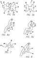
- FIGS. 1-2b show an exemplary anchor 40 that may be used in the trans-esophageal or trans-oral procedure.
- the anchor in this example is a staple 42 having an eyelet 44 and arms 46, each with a sharp tip 48.
- FIG. 1 shows the staple in an open configuration with the arms being relatively straight and parallel to one another. In use, the staple is delivered to the stomach cavity in the open configuration and then stapled so that the staple is attached to the stomach wall SW in a closed configuration as shown in FIGS. 2a and 2b .
- FIG. 2a depicts the staple attached to the stomach wall so that the arms of the staple have not punctured through the stomach wall and the eyelet of the staple positioned along the inner stomach wall within the stomach cavity SC.
- FIG. 2b shows the staple attached to the stomach wall with the arms of the staple having punctured through all layers the stomach wall.
- FIGS. 3a through 4b Another example of the anchor 40 is shown in FIGS. 3a through 4b .
- the anchor is a rivet 50 having a male portion 52 and a female portion 54.
- the male portion includes a first end 56 having a flange 58, and a second end 60 having a barb 62, although in other examples the second end may only include a post.
- the female portion of the rivet includes a tubular body 63 having first end 64 with an open bore 66, and a second end 68 having a flange 70 and an eyelet 72.
- FIG. 3b shows one example of the rivet with the male portion mated with the female portion, and in this example the rivet is generally straight.
- the male and female portions are curved as shown in FIG. 3c .
- the rivet is delivered to the stomach cavity in an open configuration, as shown in FIG. 3a , wherein the male and female portions are not attached to one another.
- the rivet is transformed into a closed configuration by inserting the second end of the male portion into the open bore of the female portion.
- a portion of the stomach wall may need to be gathered to form a fold F.
- the stomach tissue may be gathered by a vacuum or with a mechanical device such as with graspers or forceps.
- the rivet may be inserted into the stomach wall without puncturing through all of the layers of the wall, or in another example, the rivet may be inserted through the stomach wall as shown in FIG. 4b .
- the eyelet of the rivet is positioned within the stomach cavity.
- the flanges 58 and 70 provide increased surface area to contact the stomach wall, and therefore the rivet is less likely to detach.
- FIGS. 5a through 6b Yet another example of the anchor 40 is shown in FIGS. 5a through 6b .
- a rivet 74 similar to rivet 50 is shown, and therefore like reference numerals will correspond to like or similar details of the rivet.
- the rivet 74 does not include an eyelet, and instead, the rivet 74 includes a through-hole 76 that extends through the male portion 52 and the female portion 54.
- a tensioning member such as a suture or wire, can be threaded through the through-hole of the rivet.
- an anchor 80 includes a base 82, an eyelet 84 disposed on the base, and at least two through-holes 86 located on opposite sides of the eyelet.
- the anchor is delivered to the stomach cavity SC and the base of the anchor is placed against the stomach wall SW. Sutures are then threaded through the through-holes and into the stomach wall to attach the anchor as shown in FIG. 8 .
- Multiple anchors may be placed along the stomach wall in a desired pattern, and then a tensioning member threaded through the eyelets of the anchors can be tightened to cinch the anchors together, reducing the volume of the stomach cavity.
- All of the anchors disclosed herein can be constructed from titanium, stainless steel, shape-memory alloys, such as nitinol, other biocompatible metal alloys, or various polymers.
- a flexible member 88 may also be used when suturing anchors 80 to the stomach wall SW as shown in FIGS. 9a and 9b to help secure the anchor to the stomach wall by reducing any stress between the anchor and the stomach lining.
- FIG. 9 shows the surface area of the flexible member being greater than the surface area of the base.
- the flexible member may be made from a mesh, or a biocompatible polymer matrix, polyester, nylon, PTFE, collagen matrix, and may further include a metal material formed within or around the mesh to promote healing.
- the flexible member When delivering the anchor and the flexible member to the stomach cavity, the flexible member may be integrated with the anchor, pre-attached to the anchor with a suture, or the base of the anchor maybe joined to the flexible member with an adhesive.
- the flexible member and anchor are delivered separately to the stomach cavity.
- FIG. 9b shows the anchor and flexible member secured to the stomach wall with two sutures placed through the through-holes 86 and the flexible member into the stomach wall.
- the flexible member will provide increased surface area to reduce the stress applied to the stomach lining, and if the flexible member is formed of a mesh or mesh-like material, the flexible member could also increase tissue ingrowth and/or scarring, resulting in a stronger, more durable attachment. It has also been contemplated that the flexible member could be reinforced, i.e., attached to the stomach tissue via various adhesives.
- the number of anchors 40 used in the procedure could be increased.
- the minimum number of anchors that could be used in this type of procedure would be two, and the maximum number of anchors would be determined by the size of the stomach cavity and the size of the anchor.
- the "bite" size could also be increased.
- bite refers to the amount of tissue gathered or acquired by the anchor to secure itself to the stomach wall.
- the depth of the "bite” can also be increased to the point of exiting the wall of the stomach.
- a flange and/or other stress-reducing element such as a washer, could be placed on the exterior wall of the stomach. All of these examples would be helpful in reducing the stress on the stomach wall and preventing detachment of the anchor.
- FIG. 10 A partial cross-sectional view of the stomach is shown in FIG. 10 with several anchors attached to the stomach wall. This figure shows the anchors 80 sutured to the stomach wall, although any of the anchors 40, including the staple 42 and the rivets 50 and 74, could be shown because all are used in a similar manner.
- a tensioning member 90 such as a suture, wire, or zip tie, connects the anchors together by being strung through the eyelets 84 of each anchor. In a case where the rivet 74 is used, the tensioning member would be strung through the through holes 76 of the rivet.
- the tensioning member may be pre-strung through the eyelets or through-holes of the anchors before each anchor is attached to the stomach wall.
- FIG. 10a schematically illustrates the entire stomach before the anchors are cinched together.
- the first anchor to be attached to the stomach wall may be fixedly attached to the tensioning member and the other anchors may be free floating on the tensioning member.
- the free end of the tensioning member would be pulled proximally (towards the esophagus) to cinch the anchors and then tied off to the first anchor to secure the tensioning member.
- all of the anchors are free floating on the tensioning member, so that after all of the anchors have been secured around the stomach wall, there are two free ends 92 of the tensioning member that are held together by a clip 94.
- a cross section of the clip is shown in FIG. 12 , the clip is formed of a relatively thin metal, such as stainless steel, carbon, NiTi, tantalum, or other biocompatible metal and includes two lumens 96 that will house the free ends of the tensioning member.
- a clamping device 98 having a pair of clamps or pinchers 100 i s used to hold the clip i n p lace while the free ends of the tensioning member are pulled proximally. Pulling the tensioning member produces a stricture within the stomach, as shown in FIGS. 11 and 11a .
- the pinchers of the clamping device are activated to crush the clip, thereby closing the lumens of the clip to secure the free ends of the tensioning member.
- the tensioning member is then cut at a position proximal to the clip, leaving a stricture within the stomach cavity.
- the tensioning member 90 should be sufficiently flexible to allow for cinching the anchors together.
- the tensioning member may be formed from a high-tensil, corrosion-resistant material, e. g. , Kevlar fiber, braid or cable; stainless steel wire, braid or cable; polypropylene or other suture materials; or nitinol wire, braid, or cable.
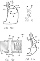
- FIGS. 13 through 14 another example is shown for reducing the volume of the stomach cavity SC.
- a device is delivered down the esophagus to the stomach cavity, to allow for in-situ "purse-string” suturing in the stomach.
- Suturing devices are known in the art, such as the auto-suturing devices from US Surgical.
- Sutures 102 are used to form a series of "bites” 104 around a portion of the stomach and an internal mechanism is used to pull or cinch the sutures to the desired tension. The suture is then tied off, resulting in a reduction in volume in the stomach cavity.
- the suture material may include Kevlar, stainless steel wire or cable, nitinol wire or cable, braided Kevlar, and other corrosion-resistant materials.
- the length of the suture material is such that after an appropriate number of sutures have been applied, two free ends 106 are left in the stomach cavity.
- the clip 94 is slid onto the free ends of the suture as shown in FIGS. 13 and 13a .
- the free ends are pulled proximally with a grasping device 110, while the pinchers 100 of the clamping device 98 are used to hold the clip in a fixed position. Once the desired tension is reached, as shown in FIG.
- the pinchers of the clamping device are activated to crush the clip, thereby securing the free ends of the suture.
- the clamping device and grasping device are removed from the stomach cavity, leaving a stricture that reduces the volume of the stomach cavity. It has also been contemplated that the free ends of the suture may be tied together in a knot.
- the strictures formed using the tensioning member 90 with anchors 40 or the suture 102 alone could be adjusted for any reason at any time.
- the tensioning member or suture could be cut, releasing the stricture.
- a new tensioning member could then be threaded through the eyelets of the anchors 40 or a new suture threaded along the stomach wall, and then tensioned to form a stricture of the desired size.
- the old tensioning member or suture and clip 94 would have to be removed from the stomach cavity.
- the tensioning member could be on a spool or other system such that the tensioning member could be tightened or loosened by rotating the spool in one direction or the other.
- the clip could be an adjustable clip 94a, such as the clip disclosed in FIG. 12a .
- the tensioning member could be adjusted to increase or decrease the tension of the tensioning member at any time without having to re-string a new tensioning member through the eyelets of the anchors.
- the adjustable clip includes a housing 151 and a locking member 152 moveable within the housing.
- a first through-hole 153 is disposed through the housing to accommodate the free end 92 of the tensioning member 90 or suture.
- the locking member also includes a second through-hole 154, that when lined-up with the first through-hole provides an unrestricted path through the housing and locking member.
- a spring 155 is disposed within the housing to bias the locking member into a locking position, where the first and second through-holes 153 and 154 are misaligned, thereby locking the free end of the tensioning member within the housing of the adjustable clip.
- the locking member of the adjustable clip would be pushed into the housing against the spring force to align the first and second through-holes into an open configuration to allow the tensioning member to move freely through the adjustable clip.
- the locking member would be released, and the force of the spring would bias the locking member, thereby misaligning the through-holes and locking the tensioning member in place. Force could be applied to the locking member with the clamping device 98 described above.
- the strictures produced by the anchors 40 and the sutures 102 may be positioned anywhere within the stomach cavity SC between the gastroesophageal j unction ("GEJ") and the pylorus, and any number of strictures may be produced to reduce the volume of the stomach.
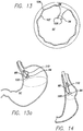
- FIG. 15a schematically shows a loose tensioning member 90 placed around a portion of the stomach cavity.
- the tensioning member may be secured by anchors to the stomach wall, or may even be the suture 102 discussed above.
- a stricture 112 is formed as shown in FIG. 15b .
- the volume of the stomach cavity is reduced, and a reservoir R is formed above the stricture in the stomach cavity.
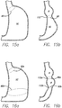
- the length of the stomach cavity SC may be effected by placing multiple strictures within the stomach cavity or by placing a single stricture in a given geometry, such as a spiral.
- FIG. 16a schematically shows a first tensioning member 90a and a second tensioning member 90b positioned within the stomach cavity, being held with anchors or sutured to the stomach wall. After tightening the tensioning members to a desired diameter, two strictures 112a and 112b are formed as shown in FIG. 16b . The placement of the second stricture further reduces the volume of the stomach cavity. Tensioning members can be tensioned so that the first stricture has a smaller, larger, or the same cross- sectional area as the second stricture.
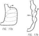
- FIG. 17a shows a tensioning member 90 spiraled around the stomach cavity, either with anchors or sutured itself. After the tensioning member is tightened to a desired tension, a spiral stricture 112c is formed as shown in FIG. 17b .
- the spiral configuration may be altered so that the inlet is larger or smaller than the outlet. Also, the tensioning member can be adjusted so that the cross-sectional area of the spiral stricture is variable or generally equal long the length of the stomach cavity.
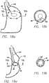
- a calibration device 120 may be used to control the cross-sectional area of the stricture.
- the calibration device which may include an inflatable balloon 122 (or other inflatable or expanding device) attached to the distal end of a catheter 124. Once the anchors 40 are secured to the stomach wall SW, the calibration device is delivered to the stomach cavity and the balloon is placed in the area of the stomach cavity to be constricted and is inflated to the desired size, as shown in FIGS. 18a and 18b (cross-sectional view).
- the calibration device would inherently be adjustable for physician control.
- the tensioning member is then tensioned until the stricture 112 conforms to the calibration device as shown in FIGS. 19a and 19b .
- the tensioning member is then terminated and the balloon is deflated and removed from the stomach cavity.
- Use of the calibration device is optional and physicians may prefer to control the size of the stricture themselves without the use of the calibration device.
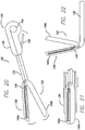
- the stapling device includes a flexible elongated body 132 having a proximal end 134 and a distal end 136.
- the elongated body can be articulated, much like an endoscope.
- the proximal end includes a handle 138 for maneuvering and activating jaws 140a and 140b of a fixation portion 142.
- a cartridge of staples can be loaded into jaw 140a of the fixation portion, and in one example, the loaded staples may be pre-strung with a tensioning member 90.
- one end of the tensioning member is fixedly attached to the first staple housed in the fixation portion.
- the other end of the tensioning member is on a spool 144 located at the proximal end of the device in the handle.
- the pre-strung tensioning member may not be fixedly attached to the first staple, but looped back inside the delivery device, giving two free ends to join together either by tying a knot or using the clip 94, which would be located within the fixation device.
- the staples would be stacked together in the fixation device with the lead staple falling into the delivery mechanism for crimping into the stomach lining.
- a spring 146 can be located in jaw 140a to advance the next staple into the delivery mechanism.
- a lever 148 located on the handle may be squeezed to actuate the jaws 140a and 140b of the fixation portion.
- the lever actuates the fixation portion using a cable, pulley, and hinges as would be known in the art.
- the lead staple is ejected from jaw 140a, through the stomach lining and jaw 140b, acting like an anvil, crimps the staple to the stomach lining. After the first staple is secured to the stomach wall, the next staple in succession is advanced by the spring into position for ejection.
- a separate device may be used to cut the tensioning member from the spool, or a blade may be incorporated into the stapler device at the distal end to severe the tensioning member after the staples have been cinched together.
- the fixation portion 142 of the stapler device 130 may be actuated using a sheath 150 that is moved distally over the hinged jaws 140a and 140b, thereby actuating the fixation portion and securing a staple into the stomach wall.
- the sheath is simply moved in the proximal direction, away from the fixation portion, allowing the jaws 140a and 140b to reset. This process can then be repeated to secure additional staples around a portion of the stomach wall.
- FIG. 22 An additional example of the distal end 136 of the stapler device 130 is shown in FIG. 22 .
- the distal end may swivel on a hinge so that the fixation portion 142 is generally perpendicular to the elongated body 132 of the device. It may be beneficial for the anchors to be placed at a angle to the axis of the delivery system.
- the vacuum could be integrated into the device itself, or could be a separate tube positioned along the device.
- the vacuum would acquire a portion or "bite" of the stomach wall that could provide a solid foundation for fixing the anchor to the tissue.
- the endoscope connects to the delivery device, for example by a snap fit, so that a standard endoscope may be used. If the standard endoscope is steerable, the elongated body of the delivery device will be sufficiently flexible or articulated near the distal end to allow for the endoscope to position the anchors. In a situation where the endoscope is not steerable, the delivery device will be articulated to allow for placement of the anchors. It also has been contemplated that fiber optics may be used to minimize the overall profile of the device.
- Anchor includes a post 182 having a distal end 184 and a proximal end 186.
- the distal end includes a sharp tip 188 for piercing through the stomach tissue, and the proximal end includes a flange 190 and an eyelet 192.
- at least the post is formed of a shape memory alloy, such as nitinol, so that when the post is inserted into the stomach tissue, a lock portion 194 forms near the distal end of the post to secure the anchor into the tissue.
- the lock portion is activated mechanically similar to a molly-bolt.
- the anchor may be fixed to the stomach wall by securing the anchor through a fold F in the stomach lining.
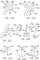
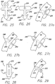
- FIGS. 24a through 24c Yet more examples of anchors are shown in FIGS. 24a through 24c , and like reference numerals are used for similar details.
- the anchors of this example are similar to fish hooks.
- a straight barb anchor 200 is shown, having a post 202 with a distal end 204 and a proximal end 206. The distal end includes a barb 208 and the proximal end includes an eyelet 210.
- FIG. 24b shows a dual barb hook 212 having two hooks 214, each with a barb at its tip.
- a triple barb hook 216 is shown in FIG. 24c , and includes three hooks.
- another example would be a single barb hook.
- These anchors could be made of a metal alloy such as stainless steel, nitinol, or other spring-like or superelastic material.
- FIGS. 24d through 24f depict similar anchors to those shown in FIGS. 24a through 24c , except that the anchors in FIGS. 24d through 24f include a flange 218 at the proximal end 206 of the post 202. Also, the anchors of FIGS. 24d through 24f include a through- hole 219 bored through the flange.
- a straight barb anchor 200a is shown in FIG. 24d
- a dual barb hook 212a is shown in FIG. 24e
- a triple barb hook 216a is shown in FIG. 24f .
- FIG. 25 Another example of an anchor 220 is shown in FIG. 25 .
- This anchor includes a post 222 having a distal end 224 and a proximal end 226.
- the distal end includes a sharp tip 228 and at least one barb 230 (two barbs are preferred) for piercing through the stomach tissue and securing to the stomach tissue.
- the proximal end includes a flange 232 and an eyelet 234.
- another anchor 240 is shown having a post 242 with a distal end 244 and a proximal end 246.
- the distal end includes a sharp tip 248 and at least one barb 250 (two barbs are preferred) for piercing through the stomach tissue and securing to the stomach tissue.
- the proximal end includes a flange 252 with a through hole 254 that runs perpendicular to the longitudinal axis of the flange.
- the posts 222 and 242 of these two anchors 220 and 250 can have varying lengths so that they pierce into the stomach tissue at a certain distance.
- FIGS. 27a through 27c show the anchor 250 having a post with varying lengths, and the anchor 220 would pierce the stomach wall SW in a similar manner.
- FIG. 27a shows the anchor with a relatively short post so that the sharp tip and barbs are positioned within the stomach wall.
- FIG. 27b shows the anchor having a post that is slightly longer than the post shown in FIG. 27a , so that the sharp tip of the anchor is pierced through the stomach wall and the barbs are positioned within the stomach wall.
- a relatively longer post positions the sharp tip and the barbs on the exterior of the stomach wall.
- the anchor has a generally tubular body 262 with a distal end 264 and a proximal end 266.
- the distal end includes a sharp tip 268 for piercing the stomach tissue, and barbs 270 are fashioned near the distal end.
- a through hole 272 is located near the proximal end for joining the anchor to the tensioning member.
- this anchor its tubular body may be cut from a tubing or stamped and rolled from a sheet. In use, the anchor is pierced into the stomach wall SW so that the barbs are located within the stomach wall and the through hole is located in the interior of the stomach cavity as shown in FIG. 29 .
- Delivering all of the anchors simultaneously to the stomach is advantageous because it can provide equal spacing of the anchors, which will help provide an equal amount of stress on each anchor.
- the delivery system is shown to include a delivery sheath 2 82, which has a distal end 284 and a proximal end (not shown).
- the delivery sheath houses at least two articulating members or delivery tubes 286 that include a distal end 288 and a proximal end (not shown).
- the distal end of the articulating members are all attached to an atraumatic tip or nosecone 290, which may be guide wire compatible.
- An actuating rod 292 is connected to the nosecone and extends through the delivery sheath to the proximal end.
- the articulating members also include a proximal member 294 and a distal member 296, which remain attached to one another by a wire 298.
- Anchors and the tensioning member may be housed in either the proximal member or the distal member of the delivery tubes. However, it is preferred that the anchors be stored in the proximal member.
- the distal end of the delivery shaft 282 is positioned in the stomach cavity through the esophagus under endoscopic guidance, and initially the articulating members or delivery tubes 286 are collapsed within the delivery sheath. It is possible that only the nosecone 290 would be extending from the delivery sheath.
- the delivery sheath is pulled proximally while the delivery tubes are held in position, as shown in FIG. 30 . Still fixing the position of the delivery tubes, the actuating rod is pulled proximally to expand the delivery tubes so that an ejection end 300 of the proximal member comes into contact with the stomach wall SW as shown in FIG. 31 .
- FIG. 32 A more detailed view of the ejection ends of the delivery tubes is shown in FIG. 32 .
- the anchors 240 are positioned inside the proximal member 294 at the ejection end, and the ejection ends of the proximal members include a slot 302 to allow the anchors to be strung together with the tensioning member 90.
- plungers or ejectors 3 04 are disposed within the proximal member of the delivery tubes, and when actuated they push the anchor into the stomach tissue.
- All of the anchors in the delivery system 280 can be pre-strung together, and in one example the tensioning member may be fixed to a first anchor, pass through each eyelet or through-hole and back through the eyelet of the first anchor, and then up into the delivery sheath 282 to the proximal end.
- the delivery tubes may be removed from the stomach cavity, and the free end of the tensioning member may be tightened at the proximal end of the system to cinch all of the anchors together. Once cinched, the free end of the tensioning member can be secured by tying a knot or other procedures, and then the extra length of the tensioning member can be cut with a separate device.
- a clip or other slideable member can be advanced over the free end of the tensioning member to a desired position to maintain the stricture formed by the cinched anchors.
- all of the anchors in the delivery system may ride freely on the tensioning member.
- the tensioning member would initiate in the delivery sheath, pass down the sheath and through the eyelets of each anchor, and up into the delivery shaft. The two free ends of the tensioning member could then be clipped together with the clip 94 and then tightened and secured as described above using the clip.
- a vacuum may be applied to the entire stomach cavity through a separate vacuum tube to draw the tissue toward the delivery system 280 and the ejection ends 300 of the delivery tubes 286 to facilitate placement of the anchors. It has been contemplated that the proximal ends of the delivery tubes could be attached to a vacuum source so that before ejecting the anchors, a vacuum can be created at the ejection end of the delivery tube to help in the placement of the anchors.
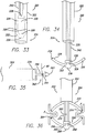
- FIGS. 33 and 34 Another example of a delivery system 320 is shown in FIGS. 33 and 34 .
- the delivery system includes a delivery sheath 322, which has a distal end 324 and a proximal end (not shown).
- the delivery sheath houses at least two articulating members or delivery tubes 326 that are flexibly or hingedly attached to a distal end 328 of a central rod 330.
- the delivery tubes each have an attached end 332 and an ejection end 334. At the distal end of the rod is an atraumatic tip such as a nosecone 336.
- the system also includes a pusher 338 attached to a hollow tube 340 that is disposed over the central rod. Anchors 342 and the tensioning member 90 may be positioned at the ejection end of the delivery tubes as shown in FIG. 35 , with the sharp tip 343 of the anchor located out of the delivery.
- the anchor 342 includes a through-hole 344 in its post 346.
- the distal end 324 of the delivery system 320 is delivered down the esophagus to the stomach cavity.
- the plurality of delivery tubes 286 are folded inside the delivery sheath 322 as shown in FIG. 33 .
- the delivery sheath is pulled proximally while the central rod is held in position to release the delivery tubes.
- the pusher 338 is pushed distally until it comes into contact with the attached ends 330 of the delivery tubes to expand the delivery tubes into an expanded configuration as shown in FIG. 34 .
- the entire system may then be pulled proximally until sharp tips 343 of the anchors 342 engage the stomach tissue.
- the anchors are then simultaneously ejected from the delivery tubes and into the stomach wall.
- the anchors are ejected one at a time.
- the anchors are ejected by a pneumatic pressure.
- the central rod can provide a pathway to direct air pressure to the delivery tubes to drive the anchors into the stomach tissue.
- the anchors may be ejected by triggering a releasing spring in the delivery tubes.
- the anchors may be held in the delivery tube by a quick release mechanism, such as a clip or a magnet, and once the anchor is seated in the stomach wall, the anchor is released.
- a vacuum can be used to collapse the stomach cavity to facilitate placement of the anchors.
- a delivery sheath 352 which has a distal end 354 and a proximal end (not shown), houses at least two distal articulating members or distal delivery tubes 356 that are flexibly or hingedly attached to a distal end 358 of a central rod 360.
- the distal delivery tubes each have an attached end 362 and an ejection end 364.
- At the distal end of the central rod is an atraumatic tip such as a nosecone 366.
- the system also includes a pusher 368 attached to a hollow tube 370 that is disposed over the central rod.
- at least two proximal articulating member or proximal delivery tubes 372 are also housed within the delivery sheath.
- the proximal delivery tubes also include an ejection end 374.
- the distal end 354 of the delivery system 350 is delivered down the esophagus to the stomach cavity.
- the plurality of delivery tubes 356 and 372 are folded inside the delivery sheath 352.
- the delivery sheath is pulled proximally while the central rod is held in position to release the proximal and distal delivery tubes.
- the pusher 368 is pushed distally until it comes into contact with the attached ends 330 of the distal delivery tubes to expand the distal delivery tubes into an expanded configuration.
- the proximal delivery tubes are self-expanding.
- the central rod 360 may then be pulled proximally in order to pinch tissue of the stomach wall SW between the proximal and distal delivery tubes as shown in FIG. 36 .
- a fold F of tissue may even be created to place the anchors through.
- the anchors are then ejected from the ends of the delivery tubes and into the stomach wall.
- the male portion 52 of rivet 50 can be loaded into one of the delivery tubes and the female portion 54 of the rivet can be housed in the other delivery tube. Therefore, when the distal delivery tubes are pulled proximally to pinch stomach tissue between the proximal and distal delivery tubes as shown in FIG. 36 , the male and female portions of the rivet can be ejected nearly at the same time to mate the male portion with the female portion through the fold of stomach tissue.
- the staples 42 could be loaded in one of the delivery tubes (either the proximal or distal tubes) and the other delivery tube could act like an anvil to crimp the arms 46 of the staple into the stomach tissue.
- a vacuum can be applied to the stomach cavity to collapse the stomach and facilitate the creation of folds F between the delivery tubes.
- the vacuum can be through the delivery tubes themselves, or a separate vacuum pod can be inserted into the stomach cavity.
- FIGS. 37 through 39 Another example of a delivery system 400 is shown in FIGS. 37 through 39 .
- the delivery system is incorporated with an articulating endoscope 402, which is known in the art.
- the endoscope includes an elongated body 404 with the capability of articulation having a proximal end (not shown) and a distal end 406.
- the delivery tube includes an ejection port 416 at the distal end.
- the anchors 240 are housed in the central lumen of the delivery tube near the distal end of the delivery tube, and the anchors may be pre-strung with the tensioning m ember 9 0. Also, a piston 418 i s disposed near the distal end of the delivery tube, and has a blunt end 420 that comes into contact with the flange 252 of the last anchor housed in the delivery tube. The piston may be spring loaded or pneumatically driven to drive the anchor into the tissue of the stomach. In use, the distal end of the delivery system is placed within the stomach cavity under endoscopic guidance. The endoscope is then articulated to direct the distal end of the delivery tube toward the portion of the stomach wall where the placement of a stricture is desired. As shown in FIG.
- the endoscope is articulated so that its distal end is curved to face the stomach wall. Once in position, the piston is actuated to drive the anchor out of the ejection end and into the stomach tissue. After the anchor is secured in the stomach wall, the endoscope can then be twisted or rotated for the placement of the next anchor.
- the anchors in this example are secured to the stomach sequentially until the last anchor has been deposited in the stomach wall. As previously discussed, the anchors are pre-strung, and when all are delivered to the stomach the tensioning m ember is tightened and secured, either by tying a knot, using the clip 94 or some other mechanical mechanism.
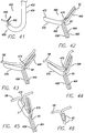
- FIGS. 40a through 40C depict the delivery tube 408 housing the triple barb hook anchors 216.
- the hook anchors are made of a spring steel, nitinol, or other spring-like or superelastic material, so that the hooks and barbs 208 can be bent within the central lumen 414 of the delivery tube.
- the hooks housed in the delivery tube are bent with the barbs are pointing distaLly (away from the eyelets), so when the hooks are ejected from the delivery tube, the barbs enter into the stomach wall SW.
- FIGS. 40b and 40c as the hooks are further ejected from the delivery tube, the elastic nature of the hooks forces the hooks and barbs to spring back to its original shape, providing a secure anchor to the stomach wall.
- FIGS. 41 through 45 Another example of a delivery system 450 is shown in FIGS. 41 through 45 .
- the delivery system includes an articulating endoscope 452, which is known in the art.
- the endoscope includes an elongated body 454 with the capability of articulation having a proximal end (not shown) and a distal end 456.
- a delivery tube 459 having a flexible elongated body 460 with a proximal end (not shown) and a distal end 462, and a central lumen 464 extending at least partially between the proximal and distal ends, is disposed within a lumen of the endoscope, as shown in FIG. 41 .
- tissue fixation device 466 At the distal end of the delivery tube is a tissue fixation device 466, that when actuated places anchors within the stomach wall.
- the tissue fixation device is very similar to the device disclosed above in FIG. 20 .
- a cartridge of staples 42 can be loaded into a first jaw 468 of the device, while a second jaw 470 includes an anvil 472 for crimping the arms of the staples when ejected from the first jaw.
- the loaded staples may be pre-strung with a tensioning member 90.
- the staples are stacked together in the fixation device with the lead staple falling into the delivery mechanism for crimping into the stomach lining.
- a spring 474 can be located in the first jaw to advance the next staple into the delivery mechanism.
- the distal end of the delivery system is positioned within the stomach, and the endoscope is articulated so that the fixation device comes in contact with the stomach wall.
- a vacuum may be applied to the central lumen of the delivery tube to facilitate engaging the stomach tissue.
- the first and second jaws of the tissue fixation device can be opened, to bring the distal end of the delivery tube closer to the stomach tissue.
- the vacuum can then be applied through the central lumen of the delivery tube to grasp onto the desired region of tissue to place an anchor.
- the jaws can then be actuated to begin closing as shown in FIGS. 44 and 45 .
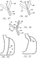
- FIG. 46 depicts a staple that was placed by the delivery device in the fold of the stomach wall.
- FIG. 47 An alternative example of the delivery device 450 is shown in FIG. 47 , wherein a vacuum tube 480 is slidably positioned within the central lumen 464 of the delivery tube 458.
- the vacuum tube can be slide distally until it comes into contact with the stomach wall.
- a vacuum is then applied through the vacuum tube, allowing the vacuum tube to grasp onto a portion of the stomach wall.
- the vacuum tube can then be pulled proximally bringing the stomach tissue closer to the distal end of the delivery tube, and thereby helping create a fold to secure an anchor through.
- FIG. 47 An alternative example of the delivery device 450 is shown in FIG. 47 , wherein a vacuum tube 480 is slidably positioned within the central lumen 464 of the delivery tube 458.
- graspers 482 such as alligator clips, are disposed at a distal end of a rod 484 that is slidably positioned within the central lumen of the delivery tube. Similar to the vacuum tube example, the rod is extended distally from the delivery tube and the graspers are actuated to grasp onto tissue. The rod is then pulled proximally, bringing the tissue within the graspers with it to facilitate the creation of a fold to secure an anchor through.
- the rivets 50 and 74 may also be used.
- the male portion 52 of the rivet 74 is shown housed in the second jaw 470 of the fixation device 466, and the female portion 54 of the rivet is housed in the first jaw 468 of the fixation device.
- the second jaw also includes a spring 474a for advancing the next male portion of the rivet in position for ejection. To place a rivet within the tissue of the stomach, the jaws are closed and the male and female portions of the rivet are ejected at nearly the same time to mate with one another.
- a device for reducing the stomach volume is a diaphragm 500 that can be deployed within a region of the stomach to divide the stomach cavity into smaller sections.
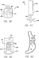
- the diaphragm is placed in a near-vertical orientation to the esophagus and extends along the stomach to the distal portion 502 of the stomach as shown in FIG. 50 .
- the diaphragm could be placed nearly perpendicular to the esophagus or at an angle, such that the cross-sectional area of the food passageway is reduced over a discrete length.
- the diaphragm is placed near the gastro esophageal junction ("GEJ"), and substantially parallel to the lesser curve of the stomach as shown in FIG. 51 , narrowing the inlet to the stomach, which slows the passage of food from the upper portion of the stomach into the remainder of the stomach.
- GEJ gastro esophageal junction
- the diaphragm 500 and anchoring mechanism is shown in FIG. 52 .
- the diaphragm is generally circular in shape, although the diaphragm may be generally oval, or any other shape that will span across the stomach cavity.
- A-plurality of anchors 220 are used to secure the diaphragm to the stomach.
- Tensioning members 90 such as sutures, are attached to the edge of the diaphragm, pass through the eyelet 234 of the anchors and back to a central eyelet 504 that is attached near the center of the diaphragm. After all of the anchors are secured to the stomach wall, the tensioning members are pulled through the central eyelet and secured to stiffen the diaphragm.
- the anchors will include a base 522 having a bottom surface 524 and a top surface 526, wherein at least one eyelet 528 will be attached to the top surface.
- the base of the anchor can be manufactured using stainless steel, carbon, NiTi, tantalum, or other biocompatible metal, or could be a composite consisting of a polymer matrix and metal, or just made from a biocompatible polymer.
- the tensioning member 90 will be strung through the eyelets on each anchor. Once the anchors are fixed to the stomach wall, the tensioning member is tensioned and constrained, forming a stricture in the stomach cavity as shown in FIG.
- the adhesive may be incorporated into the anchor itself or applied via a delivery system.
- the anchors may be adhered between two folds of tissue, such that the anchor is sandwiched between the tissue. This may create a more durable bond and may promote tissue ingrowth.
- an adhesive 530 is disposed on the bottom surface 524 of the anchor 520, and attaches the anchor to the stomach wall SW.
- the adhesive may include any one of the following, cyanoacrylate tissue adhesive such as Cyanoacrylate Ester (Loctite Corporation), UV cure adhesives, adhesive tapes or felts, adhesive foam, or other substrates, including tissue or collagen substrates modified to increase their adherent qualities.
- an adhesive capsule 532 is disposed on the top surface 526 of the anchor. The bottom surface of the anchor is positioned against the stomach wall, and the adhesive capsule can be puncture, allowing the adhesive to soak through the base 522 of the anchor to bond to the stomach wall.
- the adhesive within the adhesive capsule may be selected from the group listed above.
- Another example places the adhesive capsule on the bottom surface of the anchor as shown in FIG. 56 .
- the anchor further includes a through-hole 534 that provides a pathway to the adhesive capsule, so that a pin or other sharp instrument can puncture the adhesive capsule.
- a delivery system 550 for applying the adhesive based anchors 520 is shown in FIGS. 57 and 58 .
- the delivery system includes a delivery sheath 552 with a proximal end (not shown) and a distal end 554, with a central lumen 556 at least partially between the proximal and distal ends.
- a delivery tube 558 is positioned within the central lumen of the delivery sheath, and includes one or more articulating members 5 60 with ejection ends 562.
- the anchors are housed within a lumen 563 in the articulating members and are pushed out of the ejection ends and onto the stomach tissue. Any number of articulating members can be used, and they allow for even spacing of anchors and simultaneous deployment if desired.
- the system may also include an inflatable balloon 564 located near the distal end of the delivery sheath.
- the balloon can be inflated in the esophagus to facilitate application of positive or negative pressure to the stomach when the anchors are being pushed onto the stomach wall.
- FIG. 58 A more detailed illustration of the articulating member 560 and anchor 520 is shown in FIG. 58 .
- a plunger 566 Positioned within the lumen 563 of the articulating member is a plunger 566 with a rod 568 and a plunger end 570 that abuts against the anchor.
- the plunger is moved distally, thereby pushing the anchor out of the ejection end 562 of the articulating member 560 and against the wall of the stomach.
- the anchor shown includes an adhesive capsule 532, and therefore needs to be punctured to bond the anchor to the stomach wall.
- a needle 572 housed within a lumen of the plunger's rod can be moved or actuated in a distal direction to go through the through-hole 534 of the anchor and puncture the adhesive capsule.
- the plunger is withdrawn proximally into the articulating member, the delivery tube is withdrawn into the delivery sheath, and the inflatable balloon (if used) is deflated so the system can be removed from the stomach.
- FIG. 59 illustrates the end of the articulation member 560, that includes an adhesive tube 574 for dispensing adhesive that will bond the anchor to the stomach wall.
- Holding wires 576 formed of metal alloys such as nitinol, stainless steel, or superelastic alloy, include shaped tips 577 that are placed through the eyelets 528 of the anchor for holding the anchor in place while the adhesive bonds the anchor to the stomach wall.
- the anchor is pushed out of the ejection end 562 of the articulating member with the adhesive tube.
- An adhesive is then released from the adhesive tube that soaks through the anchor and bonds to the stomach wall. Once the anchor is secure, the adhesive tube is drawn back into the articulating member and the holding wires are also retracted into the articulating member.
- the anchor 600 is shown in FIG. 60 , and is intended to be placed between folds of stomach tissue.
- the anchor includes a post 602 having an eyelet 604 at one end and a substrate 606, either mesh or fabric, that is attached to the post.
- the substrate may include a wire 608, such as a shape-memory wire of nitinol or stainless steel to expand the substrate.
- Attached to the substrate, preferably on opposite sides of the post, are adhesive capsules 610, that when ruptured will bond the substrate, and hence the anchor in between the fold of stomach tissue.
- the adhesive may be a moisture activated adhesive, or the adhesive capsule may dissolve quickly to release the adhesive.
- an additional suture, staple or rivet may be placed through the fold and the substrate of the anchor for added support.
- tissue on either side of the substrate will grow into each other, thereby creating a durable attachment.
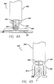
- FIGS. 61 and 62 illustrate one example of a delivery system for anchors 600.
- FIG. 61 a distal end 604 delivery sheath 602 is shown, with a delivery tube 606 and articulating members 608 extending from the distal end of the sheath.
- FIG. 62 details an ejection end 610 of the articulating member.
- a plunger 612 is housed within the articulating member for pushing the anchor out of the ejection end.
- FIG. 63 schematically illustrates anchors secured between folds of stomach tissue, and the tensioning member tensioned forming a stricture within the stomach cavity.
- a delivery system 640 in accordance with the present invention is shown in FIGS. 64 and 65 .
- a delivery sheath 642 having a proximal end (not shown) and a distal end 644, with a central lumen 646 disposed at least partially between the proximal and distal ends.
- a delivery tube 648 is housed within the central lumen, and the delivery tube includes jaws 650 that move from an open configuration to a closed configuration.
- the jaws may include a textured surface 651 to better grasp the stomach tissue without slipping.
- the delivery sheath is placed within the stomach and the delivery tube is moved distally out of the delivery sheath, and the jaws of the delivery tube are moved to its open configuration.
- the anchor is also pushed distally from the delivery tube until it comes into contact with the stomach wall SW.
- the jaws of the delivery tube are moved into its closed configuration as shown in FIG. 65 .
- the textured surfaces grip the stomach wall, thereby forming a dual fold F around the anchor.
- the jaws close with sufficient force to rupture the adhesive capsules on the anchors.
- first set of anchors 680 is secured to the stomach wall near the GEJ
- second set of anchors 682 is secured to the stomach wall near the pylorus as shown in FIG. 66 .
- the anchors in the first and second set are all strung together with the tensioning member.
- the first and second set of anchors could be replaced with a first suture and a second suture, without the use of anchors.
- a first stricture 684 and a second stricture 686 are formed within the stomach cavity as shown in FIG. 67 .
- the first stricture restricts food intake, while the second stricture delays gastric emptying.
- the size of the stoma created by the second stricture could be adjusted so that it is at least as large as the stoma created by the first stricture to prevent obstruction.
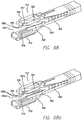
- the fixation assembly 700 includes a stapler assembly 702 connected via a flexible shaft 704 to a handle (not shown).
- the stapler assembly includes a staple cartridge 706 that can be adapted to house one or more staples 42 (not shown).
- the staples may be pre-strung together with a tension member as described above.
- the staple cartridge can also be adapted to only eject one staple 42 at its distal end, and then advance the next staple into position for ejection, or may simultaneously deploy a row of staples to create a plication in the range of 10-50 mm in length.
- the face 707 of the staple cartridge is shown in FIG. 68 to only include a single ejection hole 708.
- An anvil 709 is in apposition to the staple cartridge and is used to provide a staple closure surface when tissue to be affixed is adequately positioned between the staple cartridge and the anvil.
- the folder assembly To position tissue between the staple cartridge and the anvil, the folder assembly includes a pod member 710 and a tensioning member 712 connected to first and second actuation rods 714 and 716.
- the pod member may include a vacuum chamber or opening 718 into which tissue may be drawn therewithin.
- the tensioning member 712 includes tensioning arms 720 and 722 for forming a tissue receiving region between the arms through which tissue may be drawn in through.
- the stapler assembly can be actuated to place a staple into the fold of tissue created by the folder assembly. This device can then be positioned within the stomach cavity to place another staple into a fold of stomach tissue, or can be repositioned to deploy a row of staples simultaneously to form a longitudinal plication.
- the tissue acquisition and fixation device disclosed in the'439 application is used to create longitudinal dual fold plications within the stomach wall. Slightly altered, the tissue acquisition and fixation device could be used to place the anchors 40 described herein within dual folds. Placing anchors within dual folds could facilitate a secure connection that is less likely to deteriorate for various reasons, including that the plications distribute the load the stomach tissue acquires when it is brought together to narrow the organ which aids healing. Also, the fixation devices may be designed to incorporate at least two layers of stomach wall tissue, and sometimes additional layers including the serosal layer, which can provide greater healing durability once the tissues are in tension in the organ's reduced state.
- Folds of the present invention may include placing one anchor at a time within a fold, or multiple anchors or staples simultaneously in the form of a longitudinal plication.
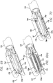
- FIG. 69 illustrates the distal working portion of the tissue acquisition and fixation device 730.
- the tissue acquisition and fixation device includes a cartridge member 732 and an anvil member 734 that are connected to a tubular member 735.
- Cartridge member may contain one or more anchors, such as staples 42, which may be actuated via controls located proximally at a handle assembly.
- a septum or barrier 736 may be removably positioned between the cartridge member and the anvil member.
- the septum is replaced with a pledget that would be incorporated into the dual fold.
- the cartridge member may include a cartridge of staples 42 and an ejection opening 738 for dispensing the staples.
- the anvil member may include an anvil 740 that corresponds to the ejection opening.
- both the cartridge and anvil members may include vacuum openings 742 and 744 that are used to acquire tissue. Applying a vacuum to the vacuum openings acquires tissue and the septum or pledget forms a barrier to create a dual fold. If a septum is used, it must be removed before the cartridge and anvil members are actuated to place a staple within the dual fold. However, if a pledget is used in-place of the septum, then the pledget would remain in position between the cartridge and anvil members as a staple or row of staples is placed within the dual fold.
- the tissue acquisition and fixation device 730 could also be adapted to place the rivets 50, 74 within a dual fold of tissue.
- the cartridge member 732 would be adapted to hold the male portion 52 of the rivet, while the anvil member 734 would be adapted to hold the female portion 54 of the rivet.
- the anvil member would also include an ejection opening 738a in apposition to the ejection opening 738 on the cartridge member.
- Both the cartridge member and anvil member would include a spring 746 to advance the next male and female portions in position for ejection. After tissue has been acquired, and the septum is removed, the cartridge and anvil members can be actuated to eject the male and female portions into the dual fold. The male and female portions will mate, securing the dual fold within the stomach cavity.
- the device as disclosed in the'883 application forms single fold plications within the stomach cavity
- the device as disclosed in the'439 application forms dual fold plications within the stomach cavity.
- the single and dual fold plications are formed by ejecting a plurality of fasteners or staple line into the stomach tissue.
- the fixation assembly 700a is shown in FIG. 68a with a face 707a include a plurality of ejection holes 708a for dispensing multiple fasteners that will form a staple line to secure the single fold.
- the tissue acquisition and fixation device 730a is shown in FIG.
- the tissue acquisition and fixation device 730a includes a pledget 736a in-place of the septum, and the pledget includes a stiffening member 737, such as a stainless steel wire to expand the pledget.
- the pledget 736a will be incorporating into the dual fold. It should be noted, that the device of the'439 may also place a single fold in the event that tissue is only acquired into one vacuum opening.
- single or dual folds may be circumferentially placed within the stomach cavity, using one of the devices disclosed in the'883 or'439 applications, and the single or dual folds may then be gathered together to reduce the stomach volume.
- a tensioning member such as a suture may be used to gather and cinch the folds together, or adjacent folds could be stapled together to reduce the stomach volume.
- the folds could be fastened with any of the anchors described above, and then the anchors could be cinched together as previously described.
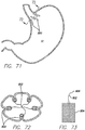
- FIG. 71 a schematic view of a stomach cavity SC is shown with multiple plications 800 placed substantially longitudinally around the circumference of the inner walls of the stomach.
- FIG. 72 is a cross-section view taken along line 72-72 of FIG. 71 , and shows the single fold plications. These single fold plications can be formed using the device disclosed in the'883 application. Gathering elements 802, or sutures, could be attached to the plications or passed through the plications, with the free ends of the gathering elements gathered in the center of the stomach cavity. In one example, a pledget 804, formed of Dacron or mesh, could have the gathering element attached to it.
- the pledget When forming the single fold plications using the device disclosed in the '883 application, the pledget could be placed on the region of tissue that is to be acquired by the t issue fixation device, and then the pledget is fixed to the fold when the plication is formed.
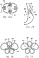
- the pledget is shown in FIG. 73 , with the gathering element attached and the free end 806 of the gathering element unattached.
- Use of the pledget distributes the load when the gathering element is tensioned.
- the pledget material may be bioabsorbable such that it absorbs over time once the tissue in the region has healed.
- Bioerodable or bioabsorbable polymers include polyanhydrides, polyorthoesters, polyesters (such as polylactic acid (PL), polyglycolic acid (PG), polyhydroxybutyric acid, polymalic acid, polyglutamic acid and polylactones) and poly (amino) acids.
- the free ends of the gathering elements are then tensioned together, thereby pulling the plications together forming a reduction in the stomach volume.
- a clip 94 as described above can then be crimped around the free ends of the gathering element to secure them.
- the cinched plications form a stricture 808 that reduces the stomach volume.
- FIG. 74 illustrates the stricture formed by the cinched folds schematically showing both longitudinal folds LF and shorter single anchor folds SAF.
- FIG. 75 which is a cross-sectional view of the stricture shows the stoma 810 formed by the cinched folds.
- Dual fold plications 811 placed around the inner surface of the stomach could also be pulled together in a similar manner.
- the dual fold plications could be created using the tissue acquisition fixation device of the'439 application.
- The'439 device could include a pledget 804 in place of the optional septum. Therefore, when the tissue is acquired using the vacuum pods of the device, the pledget would be situated in the middle of the two folds, and the cartridge and anvil member would then secure the pledget in the middle of the folds as shown in FIG. 72a .
- the gathering elements 802 would also be attached to the pledget and the free ends 806 of the gathering elements would be secured together in the middle of the stomach cavity.
- the free ends would be tensioned together, thereby pulling the dual fold plications together, creating a reduced stomach volume.
- the pledget and tensioning member may be optional and the "cinching" step can be simply the act of placing more single or dual folds in the vicinity or over the top of the folds already placed (overstapling), until the stoma or stricture is of such a diameter that the tissue fixation device can no longer be passed into position.
- the desired stoma diameter is between .25cm and 2cm, for example 1cm.
- the act of acquiring the tissue would be the equivalent to the tensioning element.
- the plications 800 could also be cinched together by stapling or fixing adjacent plications together.
- FIG. 76 shows a cross-sectional view of the stoma 810 formed by stapling adjacent plications together.
- the plications can be re-acquired by a device, such as the device disclosed in the'883 application or the device disclosed in the'439 application, and then fixed together with staples 812. Although all of the plications may be fixed together, the stomach volume would also be reduced by only fixing one adjacent plication.
- a single gathering element 802, or suture could be passed through each plication, and then the free ends of the gathering element would be tensioned to cinch or circumferentially gather the plications. The free ends of the gathering element could then be tied together or crimped together using the clip 94 or other device to secure the gathering element.
- the resulting stoma would be similar to the one shown in FIG. 76 .
- fastening lines 820 can be placed within the stomach cavity to create partitions within a hollow organ such as the stomach, as described in U. S. Serial No. 10/188,547 (“the'547 application”), titled “Method And Device For Use In Tissue Approximation And Fixation”.
- the tissue acquisition device described in the'547 application creates these partitions by acquiring and fixing together tissue taken from the posterior wall and anterior wall of the stomach.
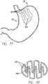
- FIG. 77 illustrates three fastening lines that create four individual lumens 822 through the stomach cavity. A cross-section taken along line 78-78 of FIG. 77 is shown in FIG. 78 .
- the partitions created by the fastening lines can be fixed together.
- a tensioning member 824 such as a suture, is placed through the fastening lines, perpendicular to the orientation of the partitions as shown in FIG. 78 .
- This restriction creates four or as many as six or more reduced lumens 826 depending on the amount of additional plications placed, or regions tensioned.
- staples or other types of anchors may be used to fix the partitions together. In either example, the stomach volume will be reduced.
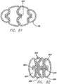
- the fastening lines 820 may also be placed with the tissue acquisition and fixation device disclosed in the'439 application to form the partitions.
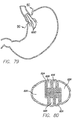
- FIG. 81 shows a cross- sectional view of the partitions formed with the'439 device. These partitions can then be fixed together in a similar manner as described above using a tensioning member 824, such as a suture or staples. This restriction will also create four or as many as six or more reduced lumens 826 as shown in FIG. 82 , depending on the amount of additional plications placed, or regions tensioned.
Landscapes
- Health & Medical Sciences (AREA)
- Surgery (AREA)
- Life Sciences & Earth Sciences (AREA)
- Animal Behavior & Ethology (AREA)
- Veterinary Medicine (AREA)
- Public Health (AREA)
- Nuclear Medicine, Radiotherapy & Molecular Imaging (AREA)
- Engineering & Computer Science (AREA)
- Biomedical Technology (AREA)
- Heart & Thoracic Surgery (AREA)
- General Health & Medical Sciences (AREA)
- Molecular Biology (AREA)
- Medical Informatics (AREA)
- Vascular Medicine (AREA)
- Reproductive Health (AREA)
- Cardiology (AREA)
- Gastroenterology & Hepatology (AREA)
- Child & Adolescent Psychology (AREA)
- Obesity (AREA)
- Nursing (AREA)
- Orthopedic Medicine & Surgery (AREA)
- Surgical Instruments (AREA)
Description
- This application is claiming priority to the following co-pending provisional applications:
U. S. Serial No. 60/544,074 filed February 13, 2004 U. S. Serial No. 60/547,961 filed February 27, 2004 U. S. Serial No. 60/552,400 filed March 12, 2004 U. S. Serial No. 60/556 ,489 filed March 26, 2004 ; andU. S. Serial No. 60/569,037 filed May 10, 2004 - The present invention pertains to medical equipment and more particularly to mechanical methods for reducing the volume of the stomach for the treatment of obesity.
- Approximately 64% of Americans are overweight and obesity is rapidly becoming an epidemic resulting in a multitude of co-morbidities (e. g. cardiovascular disease, diabetes, etc.) and enormous medical costs. Approximately $75 billion dollars are spent each year on weight-related diseases in the US alone.
- Historically, methods of weight reduction have ranged from oral pharmacological means, a multitude of diets, and various exercise programs. These approaches have generally resulted in temporary weight loss, with no or limited long-term benefit.
- In recent years, the concept of obesity being a disease has gained momentum. To that end, surgical treatments have been developed to provide a more permanent solution (e. g. stomach stapling, gastric bypass, and the like). However, these treatments are generally surgical in nature, which imply inherent risk and high cost to the patient.
- Thus, it remains desirable to develop new alternatives to provide non-invasive or minimally-invasive solutions to obesity.
-
US2003/0093117 describes an apparatus and methods for partitioning a gastro-intestinal lumen by intra-luminally reducing a local cross-section thereof. -
WO99/60931 - The present invention overcomes some or all of the shortcomings of the current techniques by providing a device according to claim 1 for minimally-invasive placement of a mechanical structure for reducing the volume of the stomach via an esophageal approach.
- The device includes anchors that are to be attached to the stomach wall using adhesive. The anchors have one or more eyelets, through which a tensioning member is strung. Once the anchors are fixed to the stomach wall, the tensioning member can be tensioned and constrained. In this manner, the wall of the stomach is not punctured or otherwise damaged and a large anchor surface area may be achieved. The adhesive is be incorporated into the anchor itself. The anchors are adhered between two folds of tissue, such that the anchor is sandwiched between the tissue. This may create a more durable bond and may promote tissue ingrowth.
- The present invention will be understood by reference to the following drawings, in which
FIGs. 60 - 65 illustrate an embodiment of the invention and the remaining figures are included for background and context, as follows. -
FIG. 1 depicts a staple. -
FIGS. 2a and 2b depict the staple ofFIG. 1 attached to the stomach wall. -
FIGS. 3a and 3b depict a rivet. -
FIGS. 4a and 4b depict the rivet ofFIGS. 3a and 3b attached to the stomach wall. -
FIGS. 5a and 5b depict another embodiment of a rivet. -
FIGS. 6a and 6b depict the rivet ofFIGS. 5a and 5b attached to the stomach wall. -
FIG. 7 depicts an anchor. -
FIG. 8 depicts the anchor ofFIG. 7 sutured to the stomach wall. -
FIG. 9a and 9b depict the anchor ofFIG. 7 attached to a flexible material. -
FIG. 10 depicts partial view of a plurality of anchors attached to the stomach wall and an untensioned tensioning member attached to the anchors. -
FIG. 10a depicts schematic view of a plurality of anchors attached to the stomach wall. -
FIG. 11 depicts a partial view of the anchors attached to the stomach wall of FIG. with the tensioning member tensioned to cinch the anchors together. -
FIG. 11a depicts a schematic view of the anchors being cinched together by tensioning the tensioning member. -
FIG. 12 depicts a cross-sectional view of a clip. -
FIG. 12a depicts a cross-sectional view of an adjustable clip. -
FIG. 13 depicts a cross-sectional view of the stomach cavity with a suture sewn around the stomach wall. -
FIG. 13a depicts a schematic view of a stomach cavity with a suture sewn around the stomach wall. -
FIG. 14 depicts a schematic view of the stomach cavity ofFIG. 13a , with the suture tensioned to form a stricture within the stomach cavity. -
FIG. 15a depicts a schematic view of a stomach cavity with a tensioning member secured to the inner stomach wall. -
FIG. 15b depicts a schematic view of the tensioning member ofFIG. 15a forming a stricture within the stomach cavity. -
FIG. 16a depicts a schematic view of a stomach cavity with a first and a second tensioning member secured to the inner stomach wall. -
FIG. 16b depicts a schematic view of the first and second tensioning members ofFIG. 16a forming a fist and a second stricture within the stomach cavity. -
FIG. 17a depicts a schematic view of a stomach cavity with a tensioning member secured to the inner stomach wall in a spiral configuration. -
FIG. 17b depicts a schematic view of the tensioning member ofFIG. 17a forming a spiral stricture within the stomach cavity. -
FIG. 18a depicts a schematic view of a balloon inflated in the stomach cavity with a tensioning member anchored to the inner stomach wall -
FIG. 18b depicts a cross-sectional view taken alongline 18b-18b ofFIG. 18a . -
FIG. 19a depicts a schematic view of the tensioning member ofFIG. 18a tensioned around the inflated balloon. -
FIG. 19b depicts a cross-sectional view taken alongline 19b-19b ofFIG. 19a . -
FIG. 20 depicts a device for securing staples to the stomach wall. -
FIG. 21 depicts a distal end of a device being actuated with a sheath. -
FIG. 22 depicts another example of the device shown inFIG. 20 . -
FIG. 23a depicts an anchor piercing the stomach wall. -
FIGS. 23b and 23c depict the anchor ofFIG. 23a in a locked configuration. -
FIGS. 24a through 24f depict examples of a hook anchor. -
FIG. 25 depicts another example of an anchor. -
FIG. 26 depicts yet another example of an anchor. -
FIGS. 27a through 27c depict varying sizes of the anchor ofFIG. 26 attached to the stomach wall. -
FIGS. 28 and 29 depicts another example of an anchor. -
FIGS. 30 through 32 depict a device for securing anchors to the stomach wall. -
FIGS. 33 through 35 depict another device for securing anchors to the stomach wall. -
FIG. 36 depicts yet another device for securing anchors to the stomach wall. -
FIGS. 37 through 39 depicts a further example of a device for securing anchors to the stomach wall. -
FIGS. 40a through 40c depict a device delivering a three bard hook anchor into tissue. -
FIGS. 41 and 42 depict another example of a device for delivering anchors to tissue. -
FIGS. 43 through 46 depict the device ofFIGS. 41 and 42 delivering a staple to the stomach tissue. -
FIG. 47 depicts an alternative example of the delivery device shown inFIGS. 41 and 42 . -
FIG. 48 depicts another alternative example of the delivery device shown inFIGS. 41 and 42 . -
FIG. 49 depicts a delivery device for delivering rivets to tissue. -
FIGS. 50 and 51 depict a schematic view of a diaphragm positioned within the stomach cavity. -
FIG. 52 depicts the diaphragm shown inFIG. 50 . -
FIG. 53 depicts a schematic view of anchors adhered to the stomach wall. -
FIGS. 54 through 56 depict an anchor attached to a stomach wall with an adhesive. -
FIGS. 57 and 58 depict a device for delivering the anchors ofFIGS. 54 through 56 . -
FIG. 59 depicts another example of a device for delivering the anchors ofFIGS. 54 through 56 . -
FIG. 60 depicts another example of an anchor. -
FIGS. 61 and 62 depict a device for delivering the anchor shown inFIG. 60 . -
FIG. 63 depicts a schematic view of anchors forming a stricture within the stomach cavity. -
FIGS. 64 and 65 depict an embodiment of a device for delivering the anchor shown inFIG. 60 . -
FIG. 66 depicts a first tensioning member secured in the stomach cavity near the GEJ and a second tensioning member secured in the stomach cavity near the pylorus. -
FIG. 67 depicts a first stricture formed near the GEJ and a second stricture formed near the pylorus. -
FIG. 68 depicts another device for delivering anchors to a fold of tissue. -
FIG. 68a depicts an alternative example of the device depicted inFIG. 68 . -
FIG. 69 depicts yet another device for delivering anchors to a fold of tissue. -
FIG. 69a depicts an alternative example of the device depicted inFIG. 69 . -
FIG. 70 depicts another alternative example of the device depicted inFIG. 69 . -
FIG. 71 depicts a schematic view of longitudinal plications disposed in the stomach cavity. -
FIG. 72 depicts a cross-sectional view taken along line 72-72 ofFIG. 71 , wherein the plications are single folds. -
FIG. 72a depicts a cross-sectional view of the stomach cavity wherein plications are dual folds. -
FIG. 73 depicts a pledget. -
FIG. 74 depicts a schematic view of a stricture created by cinching together plications within the stomach cavity, depicting both radial and longitudinally placed plications. -
FIG. 75 depicts a cross-sectional view taken along line 75-75 ofFIG. 74 . -
FIG. 76 depicts a cross-sectional view of the stomach cavity where plications are cinched together with staples. -
FIG. 77 depicts a schematic view of a stomach cavity with three fastening lines creating lumens within the stomach. -
FIG. 78 depicts a cross-sectional view taken along line 78-78 inFIG. 77 . -
FIG. 79 depicts a schematic view of the stomach cavity shown inFIG. 77 wherein the fastening lines have been cinched together. -
FIG. 80 depicts a cross-sectional view taken along line 80-80 ofFIG. 79 . -
FIG. 81 depicts a cross-sectional view of a stomach cavity with three fastening lines. -
FIG. 82 depicts a cross-sectional view of the stomach cavity shown inFIG. 81 wherein the fastening lines are cinched together. - As will be discussed in detail below, a method of reducing the volume of the stomach involves creating strictures or stomas within the stomach cavity. These strictures can be created through minimally-invasive placement of a mechanical structure for reducing the volume of the stomach via an esophageal approach. For ease of reference, the following examples will be described as being advanced transorally to the stomach, although the examples of the restricting devices can be used within other hollow body organs as well.
- One method for reducing the volume of the stomach cavity includes placing anchors along the stomach lining in a desired pattern, and then cinching the anchors together with a tensioning member, such as a suture or wire.
FIGS. 1-2b show anexemplary anchor 40 that may be used in the trans-esophageal or trans-oral procedure. The anchor in this example is a staple 42 having aneyelet 44 andarms 46, each with asharp tip 48.FIG. 1 shows the staple in an open configuration with the arms being relatively straight and parallel to one another. In use, the staple is delivered to the stomach cavity in the open configuration and then stapled so that the staple is attached to the stomach wall SW in a closed configuration as shown inFIGS. 2a and 2b . In the closed configuration the arms of the staple are bent towards one another, each being formed into a hook-like shape. The staple may or may not puncture through all layers of the stomach wall.FIG. 2a depicts the staple attached to the stomach wall so that the arms of the staple have not punctured through the stomach wall and the eyelet of the staple positioned along the inner stomach wall within the stomach cavity SC.FIG. 2b shows the staple attached to the stomach wall with the arms of the staple having punctured through all layers the stomach wall. - Another example of the
anchor 40 is shown inFIGS. 3a through 4b . Referring toFIG. 3a , the anchor is arivet 50 having amale portion 52 and afemale portion 54. The male portion includes afirst end 56 having aflange 58, and asecond end 60 having abarb 62, although in other examples the second end may only include a post. The female portion of the rivet includes atubular body 63 having first end 64 with anopen bore 66, and asecond end 68 having aflange 70 and aneyelet 72.FIG. 3b shows one example of the rivet with the male portion mated with the female portion, and in this example the rivet is generally straight. In another example, the male and female portions are curved as shown inFIG. 3c . The rivet is delivered to the stomach cavity in an open configuration, as shown inFIG. 3a , wherein the male and female portions are not attached to one another. Once in a desired position along the inner stomach wall SW, the rivet is transformed into a closed configuration by inserting the second end of the male portion into the open bore of the female portion. To insert the rivet into or through the stomach wall, a portion of the stomach wall may need to be gathered to form a fold F. The stomach tissue may be gathered by a vacuum or with a mechanical device such as with graspers or forceps. As shown inFIG. 4a , the rivet may be inserted into the stomach wall without puncturing through all of the layers of the wall, or in another example, the rivet may be inserted through the stomach wall as shown inFIG. 4b . In both examples, the eyelet of the rivet is positioned within the stomach cavity. It should be noted that theflanges - Yet another example of the
anchor 40 is shown inFIGS. 5a through 6b . Arivet 74 similar to rivet 50 is shown, and therefore like reference numerals will correspond to like or similar details of the rivet. Therivet 74 does not include an eyelet, and instead, therivet 74 includes a through-hole 76 that extends through themale portion 52 and thefemale portion 54. Once therivet 74 is positioned within or through the stomach wall SWas shown in eitherFIGS. 6a or 6b , a tensioning member, such as a suture or wire, can be threaded through the through-hole of the rivet. - Another example of the
anchor 40 is shown inFIGS. 7 and 8 . In this example, ananchor 80 includes abase 82, aneyelet 84 disposed on the base, and at least two through-holes 86 located on opposite sides of the eyelet. In use, the anchor is delivered to the stomach cavity SC and the base of the anchor is placed against the stomach wall SW. Sutures are then threaded through the through-holes and into the stomach wall to attach the anchor as shown inFIG. 8 . Multiple anchors may be placed along the stomach wall in a desired pattern, and then a tensioning member threaded through the eyelets of the anchors can be tightened to cinch the anchors together, reducing the volume of the stomach cavity. - All of the anchors disclosed herein can be constructed from titanium, stainless steel, shape-memory alloys, such as nitinol, other biocompatible metal alloys, or various polymers.
- A
flexible member 88 may also be used when suturing anchors 80 to the stomach wall SW as shown inFIGS. 9a and 9b to help secure the anchor to the stomach wall by reducing any stress between the anchor and the stomach lining.FIG. 9 shows the surface area of the flexible member being greater than the surface area of the base. Although the flexible member is shown to be round in shape, other shapes, such as oval, square, rectangle, or any polygonal shape may be used. The flexible member may be made from a mesh, or a biocompatible polymer matrix, polyester, nylon, PTFE, collagen matrix, and may further include a metal material formed within or around the mesh to promote healing. - When delivering the anchor and the flexible member to the stomach cavity, the flexible member may be integrated with the anchor, pre-attached to the anchor with a suture, or the base of the anchor maybe joined to the flexible member with an adhesive. In another example, the flexible member and anchor are delivered separately to the stomach cavity.
FIG. 9b shows the anchor and flexible member secured to the stomach wall with two sutures placed through the through-holes 86 and the flexible member into the stomach wall. The flexible member will provide increased surface area to reduce the stress applied to the stomach lining, and if the flexible member is formed of a mesh or mesh-like material, the flexible member could also increase tissue ingrowth and/or scarring, resulting in a stronger, more durable attachment. It has also been contemplated that the flexible member could be reinforced, i.e., attached to the stomach tissue via various adhesives. - There are other methods that could also be performed to reduce the stress applied to the stomach wall and to prevent erosion of the tissue/anchor interface. To reduce stress, the number of
anchors 40 used in the procedure could be increased. The minimum number of anchors that could be used in this type of procedure would be two, and the maximum number of anchors would be determined by the size of the stomach cavity and the size of the anchor. Also, the "bite" size could also be increased. The term "bite" refers to the amount of tissue gathered or acquired by the anchor to secure itself to the stomach wall. - The depth of the "bite" can also be increased to the point of exiting the wall of the stomach. In another example, a flange and/or other stress-reducing element, such as a washer, could be placed on the exterior wall of the stomach. All of these examples would be helpful in reducing the stress on the stomach wall and preventing detachment of the anchor.
- In use,
multiple anchors 40 are secured around a portion of the stomach cavity SC where the placement of a stricture is desired. The anchors are placed by various devices that will be discussed more below. A partial cross-sectional view of the stomach is shown inFIG. 10 with several anchors attached to the stomach wall. This figure shows theanchors 80 sutured to the stomach wall, although any of theanchors 40, including thestaple 42 and therivets member 90, such as a suture, wire, or zip tie, connects the anchors together by being strung through theeyelets 84 of each anchor. In a case where therivet 74 is used, the tensioning member would be strung through the throughholes 76 of the rivet. The tensioning member may be pre-strung through the eyelets or through-holes of the anchors before each anchor is attached to the stomach wall.FIG. 10a schematically illustrates the entire stomach before the anchors are cinched together. In one example the first anchor to be attached to the stomach wall may be fixedly attached to the tensioning member and the other anchors may be free floating on the tensioning member. - After the final anchor is attached, the free end of the tensioning member would be pulled proximally (towards the esophagus) to cinch the anchors and then tied off to the first anchor to secure the tensioning member. In another example shown in
FIG. 10a , all of the anchors are free floating on the tensioning member, so that after all of the anchors have been secured around the stomach wall, there are twofree ends 92 of the tensioning member that are held together by aclip 94. A cross section of the clip is shown inFIG. 12 , the clip is formed of a relatively thin metal, such as stainless steel, carbon, NiTi, tantalum, or other biocompatible metal and includes twolumens 96 that will house the free ends of the tensioning member. One lumen would also be sufficient. To form a stricture by cinching the anchors together, aclamping device 98 having a pair of clamps orpinchers 100 i s used to hold the clip i n p lace while the free ends of the tensioning member are pulled proximally. Pulling the tensioning member produces a stricture within the stomach, as shown inFIGS. 11 and11a . Once a desired tension is achieved producing a stricture of a desired size, the pinchers of the clamping device are activated to crush the clip, thereby closing the lumens of the clip to secure the free ends of the tensioning member. The tensioning member is then cut at a position proximal to the clip, leaving a stricture within the stomach cavity. - The tensioning
member 90 should be sufficiently flexible to allow for cinching the anchors together. The tensioning member may be formed from a high-tensil, corrosion-resistant material, e. g. , Kevlar fiber, braid or cable; stainless steel wire, braid or cable; polypropylene or other suture materials; or nitinol wire, braid, or cable. - Referring now to
FIGS. 13 through 14 , another example is shown for reducing the volume of the stomach cavity SC. In this example, a device is delivered down the esophagus to the stomach cavity, to allow for in-situ "purse-string" suturing in the stomach. Suturing devices are known in the art, such as the auto-suturing devices from US Surgical.Sutures 102 are used to form a series of "bites" 104 around a portion of the stomach and an internal mechanism is used to pull or cinch the sutures to the desired tension. The suture is then tied off, resulting in a reduction in volume in the stomach cavity. The suture material may include Kevlar, stainless steel wire or cable, nitinol wire or cable, braided Kevlar, and other corrosion-resistant materials. The length of the suture material is such that after an appropriate number of sutures have been applied, twofree ends 106 are left in the stomach cavity. In one example, theclip 94 is slid onto the free ends of the suture as shown inFIGS. 13 and 13a . To cinch the sutures, the free ends are pulled proximally with a graspingdevice 110, while thepinchers 100 of theclamping device 98 are used to hold the clip in a fixed position. Once the desired tension is reached, as shown inFIG. 14 , the pinchers of the clamping device are activated to crush the clip, thereby securing the free ends of the suture. The clamping device and grasping device are removed from the stomach cavity, leaving a stricture that reduces the volume of the stomach cavity. It has also been contemplated that the free ends of the suture may be tied together in a knot. - The strictures formed using the tensioning
member 90 withanchors 40 or thesuture 102 alone could be adjusted for any reason at any time. In one example, and under endoscopic guidance, the tensioning member or suture could be cut, releasing the stricture. A new tensioning member could then be threaded through the eyelets of theanchors 40 or a new suture threaded along the stomach wall, and then tensioned to form a stricture of the desired size. The old tensioning member or suture andclip 94 would have to be removed from the stomach cavity. In another example, the tensioning member could be on a spool or other system such that the tensioning member could be tightened or loosened by rotating the spool in one direction or the other. - In another example, the clip could be an
adjustable clip 94a, such as the clip disclosed inFIG. 12a . Using the adjustable clip, the tensioning member could be adjusted to increase or decrease the tension of the tensioning member at any time without having to re-string a new tensioning member through the eyelets of the anchors. The adjustable clip includes ahousing 151 and a lockingmember 152 moveable within the housing. A first through-hole 153 is disposed through the housing to accommodate thefree end 92 of the tensioningmember 90 or suture. The locking member also includes a second through-hole 154, that when lined-up with the first through-hole provides an unrestricted path through the housing and locking member. Aspring 155 is disposed within the housing to bias the locking member into a locking position, where the first and second through-holes device 98 described above. - The strictures produced by the
anchors 40 and thesutures 102 may be positioned anywhere within the stomach cavity SC between the gastroesophageal j unction ("GEJ") and the pylorus, and any number of strictures may be produced to reduce the volume of the stomach. As an example,FIG. 15a schematically shows aloose tensioning member 90 placed around a portion of the stomach cavity. The tensioning member may be secured by anchors to the stomach wall, or may even be thesuture 102 discussed above. After the tensioning member is tightened and tied off or secured to a desired diameter, astricture 112 is formed as shown inFIG. 15b . The volume of the stomach cavity is reduced, and a reservoir R is formed above the stricture in the stomach cavity. - The length of the stomach cavity SC may be effected by placing multiple strictures within the stomach cavity or by placing a single stricture in a given geometry, such as a spiral.
FIG. 16a schematically shows afirst tensioning member 90a and asecond tensioning member 90b positioned within the stomach cavity, being held with anchors or sutured to the stomach wall. After tightening the tensioning members to a desired diameter, twostrictures FIG. 16b . The placement of the second stricture further reduces the volume of the stomach cavity. Tensioning members can be tensioned so that the first stricture has a smaller, larger, or the same cross- sectional area as the second stricture. As mentioned, a single stricture can also be used to affect the length of the stomach cavity.FIG. 17a shows a tensioningmember 90 spiraled around the stomach cavity, either with anchors or sutured itself. After the tensioning member is tightened to a desired tension, aspiral stricture 112c is formed as shown inFIG. 17b . The spiral configuration may be altered so that the inlet is larger or smaller than the outlet. Also, the tensioning member can be adjusted so that the cross-sectional area of the spiral stricture is variable or generally equal long the length of the stomach cavity. - As previously described, the tensioning
member 90 orsuture 102 is tensioned or pulled proximally to cinch theanchors 40 or suture in order to form the stricture within the stomach cavity SC. In one example, a calibration device 120 may be used to control the cross-sectional area of the stricture. The calibration device which may include an inflatable balloon 122 (or other inflatable or expanding device) attached to the distal end of acatheter 124. Once theanchors 40 are secured to the stomach wall SW, the calibration device is delivered to the stomach cavity and the balloon is placed in the area of the stomach cavity to be constricted and is inflated to the desired size, as shown inFIGS. 18a and 18b (cross-sectional view). The calibration device would inherently be adjustable for physician control. The tensioning member is then tensioned until thestricture 112 conforms to the calibration device as shown inFIGS. 19a and 19b . The tensioning member is then terminated and the balloon is deflated and removed from the stomach cavity. Use of the calibration device is optional and physicians may prefer to control the size of the stricture themselves without the use of the calibration device. - Referring now to
FIGS. 20 through 22 , a tissue fixation orstapling device 130 for placingstaples 42 within the stomach cavity is shown. The stapling device includes a flexibleelongated body 132 having aproximal end 134 and adistal end 136. In one example, the elongated body can be articulated, much like an endoscope. The proximal end includes ahandle 138 for maneuvering and activatingjaws fixation portion 142. A cartridge of staples can be loaded intojaw 140a of the fixation portion, and in one example, the loaded staples may be pre-strung with a tensioningmember 90. In the example shown inFIG. 20 , one end of the tensioning member is fixedly attached to the first staple housed in the fixation portion. The other end of the tensioning member is on aspool 144 located at the proximal end of the device in the handle. In another example, the pre-strung tensioning member may not be fixedly attached to the first staple, but looped back inside the delivery device, giving two free ends to join together either by tying a knot or using theclip 94, which would be located within the fixation device. In either example, the staples would be stacked together in the fixation device with the lead staple falling into the delivery mechanism for crimping into the stomach lining. Aspring 146 can be located injaw 140a to advance the next staple into the delivery mechanism. Once the fixation portion of the device is located within the stomach cavity and the distal end is positioned at the desired area for fixation, alever 148 located on the handle may be squeezed to actuate thejaws jaw 140a, through the stomach lining andjaw 140b, acting like an anvil, crimps the staple to the stomach lining. After the first staple is secured to the stomach wall, the next staple in succession is advanced by the spring into position for ejection. - This process is repeated until all of the desired staples are secured to the stomach wall. In the example where the tensioning member is fixed to the lead staple, a separate device may be used to cut the tensioning member from the spool, or a blade may be incorporated into the stapler device at the distal end to severe the tensioning member after the staples have been cinched together.
- In another example shown in
FIG. 21 , thefixation portion 142 of thestapler device 130 may be actuated using asheath 150 that is moved distally over the hingedjaws jaws - An additional example of the
distal end 136 of thestapler device 130 is shown inFIG. 22 . In this example, the distal end may swivel on a hinge so that thefixation portion 142 is generally perpendicular to theelongated body 132 of the device. It may be beneficial for the anchors to be placed at a angle to the axis of the delivery system. - It may also be advantageous to use a vacuum in conjunction with the
delivery device 130. The vacuum could be integrated into the device itself, or could be a separate tube positioned along the device. The vacuum would acquire a portion or "bite" of the stomach wall that could provide a solid foundation for fixing the anchor to the tissue. - During the procedure for placing anchors along the stomach lining, visualization is important and may be accomplished by using an endoscope. In one example, the endoscope connects to the delivery device, for example by a snap fit, so that a standard endoscope may be used. If the standard endoscope is steerable, the elongated body of the delivery device will be sufficiently flexible or articulated near the distal end to allow for the endoscope to position the anchors. In a situation where the endoscope is not steerable, the delivery device will be articulated to allow for placement of the anchors. It also has been contemplated that fiber optics may be used to minimize the overall profile of the device.
- An
alternative anchor 180 is shown inFIGS. 23a through 23c . Anchor includes apost 182 having adistal end 184 and aproximal end 186. The distal end includes asharp tip 188 for piercing through the stomach tissue, and the proximal end includes aflange 190 and aneyelet 192. In one example, at least the post is formed of a shape memory alloy, such as nitinol, so that when the post is inserted into the stomach tissue, alock portion 194 forms near the distal end of the post to secure the anchor into the tissue. In another example, the lock portion is activated mechanically similar to a molly-bolt. As shown inFIG. 23c , the anchor may be fixed to the stomach wall by securing the anchor through a fold F in the stomach lining. - Yet more examples of anchors are shown in
FIGS. 24a through 24c , and like reference numerals are used for similar details. The anchors of this example are similar to fish hooks. InFIG. 24a , astraight barb anchor 200 is shown, having apost 202 with adistal end 204 and aproximal end 206. The distal end includes abarb 208 and the proximal end includes aneyelet 210.FIG. 24b shows adual barb hook 212 having twohooks 214, each with a barb at its tip. Atriple barb hook 216 is shown inFIG. 24c , and includes three hooks. Although not shown, another example would be a single barb hook. These anchors could be made of a metal alloy such as stainless steel, nitinol, or other spring-like or superelastic material. -
FIGS. 24d through 24f depict similar anchors to those shown inFIGS. 24a through 24c , except that the anchors inFIGS. 24d through 24f include aflange 218 at theproximal end 206 of thepost 202. Also, the anchors ofFIGS. 24d through 24f include a through-hole 219 bored through the flange. Astraight barb anchor 200a is shown inFIG. 24d , adual barb hook 212a is shown inFIG. 24e , and atriple barb hook 216a is shown inFIG. 24f . - Another example of an
anchor 220 is shown inFIG. 25 . This anchor includes apost 222 having adistal end 224 and aproximal end 226. The distal end includes asharp tip 228 and at least one barb 230 (two barbs are preferred) for piercing through the stomach tissue and securing to the stomach tissue. The proximal end includes aflange 232 and aneyelet 234. Referring now toFIG. 26 , anotheranchor 240 is shown having apost 242 with adistal end 244 and aproximal end 246. Similar to anchor 220, the distal end includes asharp tip 248 and at least one barb 250 (two barbs are preferred) for piercing through the stomach tissue and securing to the stomach tissue. The proximal end includes aflange 252 with a throughhole 254 that runs perpendicular to the longitudinal axis of the flange. Theposts anchors FIGS. 27a through 27c show theanchor 250 having a post with varying lengths, and theanchor 220 would pierce the stomach wall SW in a similar manner.FIG. 27a shows the anchor with a relatively short post so that the sharp tip and barbs are positioned within the stomach wall.FIG. 27b shows the anchor having a post that is slightly longer than the post shown inFIG. 27a , so that the sharp tip of the anchor is pierced through the stomach wall and the barbs are positioned within the stomach wall. As shown inFIG. 27c , a relatively longer post positions the sharp tip and the barbs on the exterior of the stomach wall. - Referring now to
FIG. 28 , another example of ananchor 260 is shown. The anchor has a generallytubular body 262 with adistal end 264 and aproximal end 266. - The distal end includes a
sharp tip 268 for piercing the stomach tissue, andbarbs 270 are fashioned near the distal end. A throughhole 272 is located near the proximal end for joining the anchor to the tensioning member. To manufacture this anchor, its tubular body may be cut from a tubing or stamped and rolled from a sheet. In use, the anchor is pierced into the stomach wall SW so that the barbs are located within the stomach wall and the through hole is located in the interior of the stomach cavity as shown inFIG. 29 . - An example of a
delivery system 280 will now be discussed that delivers and secures all of the anchors simultaneously to the stomach wall. Delivering all of the anchors simultaneously to the stomach is advantageous because it can provide equal spacing of the anchors, which will help provide an equal amount of stress on each anchor. - Also, the time needed to complete the procedure would be reduced by delivering the anchors simultaneously. Referring to
FIG. 30 , the delivery system is shown to include a delivery sheath 2 82, which has adistal end 284 and a proximal end (not shown). The delivery sheath houses at least two articulating members ordelivery tubes 286 that include adistal end 288 and a proximal end (not shown). The distal end of the articulating members are all attached to an atraumatic tip ornosecone 290, which may be guide wire compatible. Anactuating rod 292 is connected to the nosecone and extends through the delivery sheath to the proximal end. As shown in the figures, the articulating members also include aproximal member 294 and adistal member 296, which remain attached to one another by awire 298. Anchors and the tensioning member may be housed in either the proximal member or the distal member of the delivery tubes. However, it is preferred that the anchors be stored in the proximal member. - In use, the distal end of the
delivery shaft 282 is positioned in the stomach cavity through the esophagus under endoscopic guidance, and initially the articulating members ordelivery tubes 286 are collapsed within the delivery sheath. It is possible that only thenosecone 290 would be extending from the delivery sheath. Once the system is within the stomach cavity, the delivery sheath is pulled proximally while the delivery tubes are held in position, as shown inFIG. 30 . Still fixing the position of the delivery tubes, the actuating rod is pulled proximally to expand the delivery tubes so that anejection end 300 of the proximal member comes into contact with the stomach wall SW as shown inFIG. 31 . A more detailed view of the ejection ends of the delivery tubes is shown inFIG. 32 . - The
anchors 240 are positioned inside theproximal member 294 at the ejection end, and the ejection ends of the proximal members include aslot 302 to allow the anchors to be strung together with the tensioningmember 90. As best shown inFIG. 32 , plungers or ejectors 3 04 are disposed within the proximal member of the delivery tubes, and when actuated they push the anchor into the stomach tissue. - All of the anchors in the
delivery system 280 can be pre-strung together, and in one example the tensioning member may be fixed to a first anchor, pass through each eyelet or through-hole and back through the eyelet of the first anchor, and then up into thedelivery sheath 282 to the proximal end. After simultaneously ejecting all of the anchors from thedelivery tubes 286 into the stomach wall, the delivery tubes may be removed from the stomach cavity, and the free end of the tensioning member may be tightened at the proximal end of the system to cinch all of the anchors together. Once cinched, the free end of the tensioning member can be secured by tying a knot or other procedures, and then the extra length of the tensioning member can be cut with a separate device. A clip or other slideable member can be advanced over the free end of the tensioning member to a desired position to maintain the stricture formed by the cinched anchors. In another example, all of the anchors in the delivery system may ride freely on the tensioning member. In this configuration, the tensioning member would initiate in the delivery sheath, pass down the sheath and through the eyelets of each anchor, and up into the delivery shaft. The two free ends of the tensioning member could then be clipped together with theclip 94 and then tightened and secured as described above using the clip. - In one example, a vacuum may be applied to the entire stomach cavity through a separate vacuum tube to draw the tissue toward the
delivery system 280 and the ejection ends 300 of thedelivery tubes 286 to facilitate placement of the anchors. It has been contemplated that the proximal ends of the delivery tubes could be attached to a vacuum source so that before ejecting the anchors, a vacuum can be created at the ejection end of the delivery tube to help in the placement of the anchors. - Another example of a
delivery system 320 is shown inFIGS. 33 and 34 . The delivery system includes adelivery sheath 322, which has adistal end 324 and a proximal end (not shown). The delivery sheath houses at least two articulating members ordelivery tubes 326 that are flexibly or hingedly attached to adistal end 328 of acentral rod 330. - The delivery tubes each have an attached
end 332 and anejection end 334. At the distal end of the rod is an atraumatic tip such as anosecone 336. The system also includes apusher 338 attached to ahollow tube 340 that is disposed over the central rod.Anchors 342 and the tensioningmember 90 may be positioned at the ejection end of the delivery tubes as shown inFIG. 35 , with thesharp tip 343 of the anchor located out of the delivery. - In this example the
anchor 342 includes a through-hole 344 in itspost 346. - In use, the
distal end 324 of thedelivery system 320 is delivered down the esophagus to the stomach cavity. As the system is delivered, the plurality ofdelivery tubes 286 are folded inside thedelivery sheath 322 as shown inFIG. 33 . Once in position within the stomach cavity, the delivery sheath is pulled proximally while the central rod is held in position to release the delivery tubes. Next, thepusher 338 is pushed distally until it comes into contact with the attached ends 330 of the delivery tubes to expand the delivery tubes into an expanded configuration as shown inFIG. 34 . The entire system may then be pulled proximally untilsharp tips 343 of theanchors 342 engage the stomach tissue. The anchors are then simultaneously ejected from the delivery tubes and into the stomach wall. - It is also possible for the anchors to be ejected one at a time. In one example, the anchors are ejected by a pneumatic pressure. In this example, the central rod can provide a pathway to direct air pressure to the delivery tubes to drive the anchors into the stomach tissue. In another example, the anchors may be ejected by triggering a releasing spring in the delivery tubes. Still in another example, the anchors may be held in the delivery tube by a quick release mechanism, such as a clip or a magnet, and once the anchor is seated in the stomach wall, the anchor is released. Also, similar to the above example, a vacuum can be used to collapse the stomach cavity to facilitate placement of the anchors.
- Yet another example of a
delivery system 350 is show inFIG. 36 . In this system, adelivery sheath 352, which has adistal end 354 and a proximal end (not shown), houses at least two distal articulating members ordistal delivery tubes 356 that are flexibly or hingedly attached to adistal end 358 of acentral rod 360. The distal delivery tubes each have an attachedend 362 and anejection end 364. At the distal end of the central rod is an atraumatic tip such as anosecone 366. The system also includes apusher 368 attached to ahollow tube 370 that is disposed over the central rod. In this example, at least two proximal articulating member orproximal delivery tubes 372 are also housed within the delivery sheath. The proximal delivery tubes also include anejection end 374. - In use, the
distal end 354 of thedelivery system 350 is delivered down the esophagus to the stomach cavity. As the system is delivered, the plurality ofdelivery tubes delivery sheath 352. Once in position within the stomach cavity, the delivery sheath is pulled proximally while the central rod is held in position to release the proximal and distal delivery tubes. Next, thepusher 368 is pushed distally until it comes into contact with the attached ends 330 of the distal delivery tubes to expand the distal delivery tubes into an expanded configuration. In one example the proximal delivery tubes are self-expanding. Thecentral rod 360 may then be pulled proximally in order to pinch tissue of the stomach wall SW between the proximal and distal delivery tubes as shown inFIG. 36 . A fold F of tissue may even be created to place the anchors through. The anchors are then ejected from the ends of the delivery tubes and into the stomach wall. - Many of the anchors described above can be ejected from the distal and
proximal delivery tubes delivery system 350. For instance, themale portion 52 ofrivet 50 can be loaded into one of the delivery tubes and thefemale portion 54 of the rivet can be housed in the other delivery tube. Therefore, when the distal delivery tubes are pulled proximally to pinch stomach tissue between the proximal and distal delivery tubes as shown inFIG. 36 , the male and female portions of the rivet can be ejected nearly at the same time to mate the male portion with the female portion through the fold of stomach tissue. In another example, thestaples 42 could be loaded in one of the delivery tubes (either the proximal or distal tubes) and the other delivery tube could act like an anvil to crimp thearms 46 of the staple into the stomach tissue. - It should be noted that before ejecting any of the anchors from the
delivery tubes delivery system 350, a vacuum can be applied to the stomach cavity to collapse the stomach and facilitate the creation of folds F between the delivery tubes. The vacuum can be through the delivery tubes themselves, or a separate vacuum pod can be inserted into the stomach cavity. - Another example of a
delivery system 400 is shown inFIGS. 37 through 39 . In this example, the delivery system is incorporated with an articulatingendoscope 402, which is known in the art. The endoscope includes anelongated body 404 with the capability of articulation having a proximal end (not shown) and adistal end 406. Adelivery tube 408 having a flexibleelongated body 410 with a proximal end (not shown) and adistal end 412, and acentral lumen 414 extending at least partially between the proximal and distal ends, is disposed within a lumen of the endoscope, as shown inFIG. 37 . The delivery tube includes anejection port 416 at the distal end. Theanchors 240 are housed in the central lumen of the delivery tube near the distal end of the delivery tube, and the anchors may be pre-strung with the tensioning m ember 9 0. Also, apiston 418 i s disposed near the distal end of the delivery tube, and has a blunt end 420 that comes into contact with theflange 252 of the last anchor housed in the delivery tube. The piston may be spring loaded or pneumatically driven to drive the anchor into the tissue of the stomach. In use, the distal end of the delivery system is placed within the stomach cavity under endoscopic guidance. The endoscope is then articulated to direct the distal end of the delivery tube toward the portion of the stomach wall where the placement of a stricture is desired. As shown inFIG. 38 , the endoscope is articulated so that its distal end is curved to face the stomach wall. Once in position, the piston is actuated to drive the anchor out of the ejection end and into the stomach tissue. After the anchor is secured in the stomach wall, the endoscope can then be twisted or rotated for the placement of the next anchor. The anchors in this example are secured to the stomach sequentially until the last anchor has been deposited in the stomach wall. As previously discussed, the anchors are pre-strung, and when all are delivered to the stomach the tensioning m ember is tightened and secured, either by tying a knot, using theclip 94 or some other mechanical mechanism. - The
delivery system 400 could also be used with other types of anchors as well. For instance,FIGS. 40a through 40C depict thedelivery tube 408 housing the triple barb hook anchors 216. As mentioned above, the hook anchors are made of a spring steel, nitinol, or other spring-like or superelastic material, so that the hooks andbarbs 208 can be bent within thecentral lumen 414 of the delivery tube. As shown inFIG. 40a , the hooks housed in the delivery tube are bent with the barbs are pointing distaLly (away from the eyelets), so when the hooks are ejected from the delivery tube, the barbs enter into the stomach wall SW. Referring toFIGS. 40b and 40c , as the hooks are further ejected from the delivery tube, the elastic nature of the hooks forces the hooks and barbs to spring back to its original shape, providing a secure anchor to the stomach wall. - Another example of a
delivery system 450 is shown inFIGS. 41 through 45 . The delivery system includes an articulatingendoscope 452, which is known in the art. The endoscope includes anelongated body 454 with the capability of articulation having a proximal end (not shown) and adistal end 456. A delivery tube 459 having a flexibleelongated body 460 with a proximal end (not shown) and adistal end 462, and acentral lumen 464 extending at least partially between the proximal and distal ends, is disposed within a lumen of the endoscope, as shown inFIG. 41 . At the distal end of the delivery tube is atissue fixation device 466, that when actuated places anchors within the stomach wall. The tissue fixation device is very similar to the device disclosed above inFIG. 20 . In the example shown, a cartridge ofstaples 42 can be loaded into afirst jaw 468 of the device, while asecond jaw 470 includes ananvil 472 for crimping the arms of the staples when ejected from the first jaw. As previously discussed with reference toFIG. 20 , the loaded staples may be pre-strung with a tensioningmember 90. The staples are stacked together in the fixation device with the lead staple falling into the delivery mechanism for crimping into the stomach lining. Aspring 474 can be located in the first jaw to advance the next staple into the delivery mechanism. In use, the distal end of the delivery system is positioned within the stomach, and the endoscope is articulated so that the fixation device comes in contact with the stomach wall. In one example, a vacuum may be applied to the central lumen of the delivery tube to facilitate engaging the stomach tissue. Referring toFIG. 43 , the first and second jaws of the tissue fixation device can be opened, to bring the distal end of the delivery tube closer to the stomach tissue. The vacuum can then be applied through the central lumen of the delivery tube to grasp onto the desired region of tissue to place an anchor. The jaws can then be actuated to begin closing as shown inFIGS. 44 and 45 . As the jaws close, the tissue of the stomach wall SW is still being held by the vacuum pressure, thereby creating a fold F to place the anchor through. To help facilitate in forming the fold, the inside surfaces of thejaws staple 42 is ejected from the first jaw, through the tissue fold where the anvil of the second jaw crimps the staple in place. After the first staple is secured to the stomach wall, the next staple in secession is advanced by the spring into position for ejection. This process is repeated until all of the desired staples are secured to the stomach wall.FIG. 46 depicts a staple that was placed by the delivery device in the fold of the stomach wall. - An alternative example of the
delivery device 450 is shown inFIG. 47 , wherein avacuum tube 480 is slidably positioned within thecentral lumen 464 of thedelivery tube 458. After the distal end of the delivery device is positioned within the stomach, and the endoscope is articulated so the tissue fixation device is pointed in the direction of the region of the stomach wall, the vacuum tube can be slide distally until it comes into contact with the stomach wall. A vacuum is then applied through the vacuum tube, allowing the vacuum tube to grasp onto a portion of the stomach wall. The vacuum tube can then be pulled proximally bringing the stomach tissue closer to the distal end of the delivery tube, and thereby helping create a fold to secure an anchor through.FIG. 48 shows another example, whereingraspers 482, such as alligator clips, are disposed at a distal end of arod 484 that is slidably positioned within the central lumen of the delivery tube. Similar to the vacuum tube example, the rod is extended distally from the delivery tube and the graspers are actuated to grasp onto tissue. The rod is then pulled proximally, bringing the tissue within the graspers with it to facilitate the creation of a fold to secure an anchor through. - Although
staples 42 are described with the use of thedelivery device 450, other anchors may be used as well. For instance, therivets FIG. 49 , themale portion 52 of therivet 74 is shown housed in thesecond jaw 470 of thefixation device 466, and thefemale portion 54 of the rivet is housed in thefirst jaw 468 of the fixation device. In this example, the second jaw also includes aspring 474a for advancing the next male portion of the rivet in position for ejection. To place a rivet within the tissue of the stomach, the jaws are closed and the male and female portions of the rivet are ejected at nearly the same time to mate with one another. - Another example of a device for reducing the stomach volume is a
diaphragm 500 that can be deployed within a region of the stomach to divide the stomach cavity into smaller sections. In one example, the diaphragm is placed in a near-vertical orientation to the esophagus and extends along the stomach to thedistal portion 502 of the stomach as shown inFIG. 50 . Alternatively, the diaphragm could be placed nearly perpendicular to the esophagus or at an angle, such that the cross-sectional area of the food passageway is reduced over a discrete length. In another example, the diaphragm is placed near the gastro esophageal junction ("GEJ"), and substantially parallel to the lesser curve of the stomach as shown inFIG. 51 , narrowing the inlet to the stomach, which slows the passage of food from the upper portion of the stomach into the remainder of the stomach. - One example of the
diaphragm 500 and anchoring mechanism is shown inFIG. 52 . The diaphragm is generally circular in shape, although the diaphragm may be generally oval, or any other shape that will span across the stomach cavity. A-plurality ofanchors 220, although other types of anchors may be used as well, are used to secure the diaphragm to the stomach. Tensioningmembers 90, such as sutures, are attached to the edge of the diaphragm, pass through theeyelet 234 of the anchors and back to acentral eyelet 504 that is attached near the center of the diaphragm. After all of the anchors are secured to the stomach wall, the tensioning members are pulled through the central eyelet and secured to stiffen the diaphragm. - Another method for reducing the stomach volume is to attach a plurality of
anchors 520 to the stomach wall using adhesive. Referring toFIGS. 53 through 56 , the anchors will include a base 522 having a bottom surface 524 and atop surface 526, wherein at least oneeyelet 528 will be attached to the top surface. The base of the anchor can be manufactured using stainless steel, carbon, NiTi, tantalum, or other biocompatible metal, or could be a composite consisting of a polymer matrix and metal, or just made from a biocompatible polymer. The tensioningmember 90 will be strung through the eyelets on each anchor. Once the anchors are fixed to the stomach wall, the tensioning member is tensioned and constrained, forming a stricture in the stomach cavity as shown inFIG. 53 . In this manner, the wall of the stomach is not punctured or otherwise damaged and a large anchor surface area may be achieved. The adhesive may be incorporated into the anchor itself or applied via a delivery system. In other examples, the anchors may be adhered between two folds of tissue, such that the anchor is sandwiched between the tissue. This may create a more durable bond and may promote tissue ingrowth. - Referring to
FIG. 54 , an adhesive 530 is disposed on the bottom surface 524 of theanchor 520, and attaches the anchor to the stomach wall SW. The adhesive may include any one of the following, cyanoacrylate tissue adhesive such as Cyanoacrylate Ester (Loctite Corporation), UV cure adhesives, adhesive tapes or felts, adhesive foam, or other substrates, including tissue or collagen substrates modified to increase their adherent qualities. In another example, as shown inFIG. 55 , anadhesive capsule 532 is disposed on thetop surface 526 of the anchor. The bottom surface of the anchor is positioned against the stomach wall, and the adhesive capsule can be puncture, allowing the adhesive to soak through thebase 522 of the anchor to bond to the stomach wall. In this example, the adhesive within the adhesive capsule may be selected from the group listed above. Another example places the adhesive capsule on the bottom surface of the anchor as shown inFIG. 56 . In this example, the anchor further includes a through-hole 534 that provides a pathway to the adhesive capsule, so that a pin or other sharp instrument can puncture the adhesive capsule. - A
delivery system 550 for applying the adhesive basedanchors 520 is shown inFIGS. 57 and 58 . The delivery system includes adelivery sheath 552 with a proximal end (not shown) and adistal end 554, with acentral lumen 556 at least partially between the proximal and distal ends. Adelivery tube 558 is positioned within the central lumen of the delivery sheath, and includes one or more articulatingmembers 5 60 with ejection ends 562. The anchors are housed within alumen 563 in the articulating members and are pushed out of the ejection ends and onto the stomach tissue. Any number of articulating members can be used, and they allow for even spacing of anchors and simultaneous deployment if desired. The system may also include aninflatable balloon 564 located near the distal end of the delivery sheath. During delivery, the balloon can be inflated in the esophagus to facilitate application of positive or negative pressure to the stomach when the anchors are being pushed onto the stomach wall. - A more detailed illustration of the articulating
member 560 andanchor 520 is shown inFIG. 58 . Positioned within thelumen 563 of the articulating member is aplunger 566 with arod 568 and aplunger end 570 that abuts against the anchor. Once the system is in position within the stomach, the plunger is moved distally, thereby pushing the anchor out of theejection end 562 of the articulatingmember 560 and against the wall of the stomach. The anchor shown includes anadhesive capsule 532, and therefore needs to be punctured to bond the anchor to the stomach wall. To puncture the adhesive capsule, aneedle 572 housed within a lumen of the plunger's rod can be moved or actuated in a distal direction to go through the through-hole 534 of the anchor and puncture the adhesive capsule. After the anchor bonds to the stomach wall, the plunger is withdrawn proximally into the articulating member, the delivery tube is withdrawn into the delivery sheath, and the inflatable balloon (if used) is deflated so the system can be removed from the stomach. - In an alternative method, the adhesive can be delivered via the delivery system, rather than being incorporated into the
anchor 520.FIG. 59 illustrates the end of thearticulation member 560, that includes anadhesive tube 574 for dispensing adhesive that will bond the anchor to the stomach wall. Holdingwires 576, formed of metal alloys such as nitinol, stainless steel, or superelastic alloy, include shapedtips 577 that are placed through theeyelets 528 of the anchor for holding the anchor in place while the adhesive bonds the anchor to the stomach wall. In use, the anchor is pushed out of theejection end 562 of the articulating member with the adhesive tube. An adhesive is then released from the adhesive tube that soaks through the anchor and bonds to the stomach wall. Once the anchor is secure, the adhesive tube is drawn back into the articulating member and the holding wires are also retracted into the articulating member. - Another example of an
anchor 600 is shown inFIG. 60 , and is intended to be placed between folds of stomach tissue. The anchor includes apost 602 having aneyelet 604 at one end and asubstrate 606, either mesh or fabric, that is attached to the post. The substrate may include awire 608, such as a shape-memory wire of nitinol or stainless steel to expand the substrate. Attached to the substrate, preferably on opposite sides of the post, areadhesive capsules 610, that when ruptured will bond the substrate, and hence the anchor in between the fold of stomach tissue. The adhesive may be a moisture activated adhesive, or the adhesive capsule may dissolve quickly to release the adhesive. Once the anchor is secured between a fold of tissue, an additional suture, staple or rivet may be placed through the fold and the substrate of the anchor for added support. As the anchor heals in between the tissue fold, tissue on either side of the substrate will grow into each other, thereby creating a durable attachment. -
FIGS. 61 and 62 illustrate one example of a delivery system foranchors 600. - In this delivery system, all of the anchors may be delivered simultaneously. This delivery system is similar to the system disclosed in
FIGS. 57 and 58 . Referring toFIG. 61 , adistal end 604delivery sheath 602 is shown, with adelivery tube 606 and articulatingmembers 608 extending from the distal end of the sheath.FIG. 62 details anejection end 610 of the articulating member. Aplunger 612 is housed within the articulating member for pushing the anchor out of the ejection end. There is also aslot 614 disposed at the ejection end of the articulating member, so that the tensioning member can be pre-strung through all of the anchors.FIG. 63 schematically illustrates anchors secured between folds of stomach tissue, and the tensioning member tensioned forming a stricture within the stomach cavity. - A
delivery system 640 in accordance with the present invention is shown inFIGS. 64 and 65 . Adelivery sheath 642 having a proximal end (not shown) and adistal end 644, with a central lumen 646 disposed at least partially between the proximal and distal ends. Adelivery tube 648 is housed within the central lumen, and the delivery tube includesjaws 650 that move from an open configuration to a closed configuration. The jaws may include atextured surface 651 to better grasp the stomach tissue without slipping. There is also aplunger 652 located within a lumen of the delivery tube. The plunger abuts theanchor 620 which is housed within the delivery tube. In use, the delivery sheath is placed within the stomach and the delivery tube is moved distally out of the delivery sheath, and the jaws of the delivery tube are moved to its open configuration. The anchor is also pushed distally from the delivery tube until it comes into contact with the stomach wall SW. With the plunger holding the anchor in place, the jaws of the delivery tube are moved into its closed configuration as shown inFIG. 65 . As the jaws move to the closed configuration, the textured surfaces grip the stomach wall, thereby forming a dual fold F around the anchor. In one embodiment, the jaws close with sufficient force to rupture the adhesive capsules on the anchors. After the anchor is bonded to the fold, the delivery system is removed from the stomach cavity. - All of the anchors and delivery systems described above place anchors in the stomach wall and cinch them together to form a stricture within the stomach. Multiple strictures may disposed within the stomach. In one embodiment, a first set of
anchors 680 is secured to the stomach wall near the GEJ, and a second set ofanchors 682 is secured to the stomach wall near the pylorus as shown inFIG. 66 . The anchors in the first and second set are all strung together with the tensioning member. In another embodiment, the first and second set of anchors could be replaced with a first suture and a second suture, without the use of anchors. Once the tensioning members are tensioned and fixed, afirst stricture 684 and asecond stricture 686 are formed within the stomach cavity as shown inFIG. 67 . The first stricture restricts food intake, while the second stricture delays gastric emptying. The size of the stoma created by the second stricture could be adjusted so that it is at least as large as the stoma created by the first stricture to prevent obstruction. - Other devices could also be used to place the anchors discussed above in the stomach wall. For instance, the system shown having a folder assembly and a fixation assembly as disclosed in
U. S. Serial No. 10/773, 883 FIG. 68 . Thefixation assembly 700 includes astapler assembly 702 connected via aflexible shaft 704 to a handle (not shown). The stapler assembly includes astaple cartridge 706 that can be adapted to house one or more staples 42 (not shown). In the staple cartridge, the staples may be pre-strung together with a tension member as described above. The staple cartridge can also be adapted to only eject onestaple 42 at its distal end, and then advance the next staple into position for ejection, or may simultaneously deploy a row of staples to create a plication in the range of 10-50 mm in length. Theface 707 of the staple cartridge is shown inFIG. 68 to only include asingle ejection hole 708. Ananvil 709 is in apposition to the staple cartridge and is used to provide a staple closure surface when tissue to be affixed is adequately positioned between the staple cartridge and the anvil. To position tissue between the staple cartridge and the anvil, the folder assembly includes apod member 710 and atensioning member 712 connected to first and second actuation rods 714 and 716. The pod member may include a vacuum chamber or opening 718 into which tissue may be drawn therewithin. The tensioningmember 712 includes tensioningarms - Another device that could also be used to place the anchors discussed above in the stomach wall is disclosed in
U. S. Serial No. 10/797,439 anchors 40 described herein within dual folds. Placing anchors within dual folds could facilitate a secure connection that is less likely to deteriorate for various reasons, including that the plications distribute the load the stomach tissue acquires when it is brought together to narrow the organ which aids healing. Also, the fixation devices may be designed to incorporate at least two layers of stomach wall tissue, and sometimes additional layers including the serosal layer, which can provide greater healing durability once the tissues are in tension in the organ's reduced state. - Similar teachings are set forth in
U. S. Serial Number 10/188,547 FIG. 69 illustrates the distal working portion of the tissue acquisition andfixation device 730. The tissue acquisition and fixation device includes acartridge member 732 and ananvil member 734 that are connected to atubular member 735. Cartridge member may contain one or more anchors, such asstaples 42, which may be actuated via controls located proximally at a handle assembly. A septum orbarrier 736 may be removably positioned between the cartridge member and the anvil member. In one example, the septum is replaced with a pledget that would be incorporated into the dual fold. The cartridge member may include a cartridge ofstaples 42 and anejection opening 738 for dispensing the staples. The anvil member may include ananvil 740 that corresponds to the ejection opening. Also, both the cartridge and anvil members may includevacuum openings - The tissue acquisition and
fixation device 730 could also be adapted to place therivets cartridge member 732 would be adapted to hold themale portion 52 of the rivet, while theanvil member 734 would be adapted to hold thefemale portion 54 of the rivet. The anvil member would also include anejection opening 738a in apposition to the ejection opening 738 on the cartridge member. Both the cartridge member and anvil member would include aspring 746 to advance the next male and female portions in position for ejection. After tissue has been acquired, and the septum is removed, the cartridge and anvil members can be actuated to eject the male and female portions into the dual fold. The male and female portions will mate, securing the dual fold within the stomach cavity. - The device as disclosed in the'883 application forms single fold plications within the stomach cavity, and the device as disclosed in the'439 application forms dual fold plications within the stomach cavity. As disclosed in the'883 and'439 applications, the single and dual fold plications are formed by ejecting a plurality of fasteners or staple line into the stomach tissue. The
fixation assembly 700a is shown inFIG. 68a with aface 707a include a plurality ofejection holes 708a for dispensing multiple fasteners that will form a staple line to secure the single fold. The tissue acquisition and fixation device 730a is shown inFIG. 69a with thecartridge member 732a including a plurality ofejection openings 738a for dispensing multiple fasteners for forming a staple line to secure the dual fold. Also, the tissue acquisition and fixation device 730a includes a pledget 736a in-place of the septum, and the pledget includes a stiffeningmember 737, such as a stainless steel wire to expand the pledget. In this example, the pledget 736a will be incorporating into the dual fold. It should be noted, that the device of the'439 may also place a single fold in the event that tissue is only acquired into one vacuum opening. In one example, single or dual folds may be circumferentially placed within the stomach cavity, using one of the devices disclosed in the'883 or'439 applications, and the single or dual folds may then be gathered together to reduce the stomach volume. A tensioning member such as a suture may be used to gather and cinch the folds together, or adjacent folds could be stapled together to reduce the stomach volume. Yet in another example, the folds could be fastened with any of the anchors described above, and then the anchors could be cinched together as previously described. - Referring to
FIG. 71 , a schematic view of a stomach cavity SC is shown withmultiple plications 800 placed substantially longitudinally around the circumference of the inner walls of the stomach.FIG. 72 is a cross-section view taken along line 72-72 ofFIG. 71 , and shows the single fold plications. These single fold plications can be formed using the device disclosed in the'883 application. Gatheringelements 802, or sutures, could be attached to the plications or passed through the plications, with the free ends of the gathering elements gathered in the center of the stomach cavity. In one example, apledget 804, formed of Dacron or mesh, could have the gathering element attached to it. - When forming the single fold plications using the device disclosed in the '883 application, the pledget could be placed on the region of tissue that is to be acquired by the t issue fixation device, and then the pledget is fixed to the fold when the plication is formed. The pledget is shown in
FIG. 73 , with the gathering element attached and thefree end 806 of the gathering element unattached. Use of the pledget distributes the load when the gathering element is tensioned. Furthermore, the pledget material may be bioabsorbable such that it absorbs over time once the tissue in the region has healed. Bioerodable or bioabsorbable polymers include polyanhydrides, polyorthoesters, polyesters (such as polylactic acid (PL), polyglycolic acid (PG), polyhydroxybutyric acid, polymalic acid, polyglutamic acid and polylactones) and poly (amino) acids. The free ends of the gathering elements are then tensioned together, thereby pulling the plications together forming a reduction in the stomach volume. Aclip 94 as described above can then be crimped around the free ends of the gathering element to secure them. The cinched plications form astricture 808 that reduces the stomach volume.FIG. 74 illustrates the stricture formed by the cinched folds schematically showing both longitudinal folds LF and shorter single anchor folds SAF. Also,FIG. 75 , which is a cross-sectional view of the stricture shows thestoma 810 formed by the cinched folds. -
Dual fold plications 811 placed around the inner surface of the stomach could also be pulled together in a similar manner. The dual fold plications could be created using the tissue acquisition fixation device of the'439 application. The'439 device could include apledget 804 in place of the optional septum. Therefore, when the tissue is acquired using the vacuum pods of the device, the pledget would be situated in the middle of the two folds, and the cartridge and anvil member would then secure the pledget in the middle of the folds as shown inFIG. 72a . Thegathering elements 802 would also be attached to the pledget and the free ends 806 of the gathering elements would be secured together in the middle of the stomach cavity. As with the above example, the free ends would be tensioned together, thereby pulling the dual fold plications together, creating a reduced stomach volume. In some examples of the present invention whether a single or multiple anchor (s) and/or fold (s) are placed, the pledget and tensioning member may be optional and the "cinching" step can be simply the act of placing more single or dual folds in the vicinity or over the top of the folds already placed (overstapling), until the stoma or stricture is of such a diameter that the tissue fixation device can no longer be passed into position. In all cases, the desired stoma diameter is between .25cm and 2cm, for example 1cm. In these examples, the act of acquiring the tissue would be the equivalent to the tensioning element. - The
plications 800 could also be cinched together by stapling or fixing adjacent plications together.FIG. 76 shows a cross-sectional view of thestoma 810 formed by stapling adjacent plications together. In this example, the plications can be re-acquired by a device, such as the device disclosed in the'883 application or the device disclosed in the'439 application, and then fixed together withstaples 812. Although all of the plications may be fixed together, the stomach volume would also be reduced by only fixing one adjacent plication. Yet in another example, asingle gathering element 802, or suture, could be passed through each plication, and then the free ends of the gathering element would be tensioned to cinch or circumferentially gather the plications. The free ends of the gathering element could then be tied together or crimped together using theclip 94 or other device to secure the gathering element. The resulting stoma would be similar to the one shown inFIG. 76 . - In another example,
fastening lines 820 can be placed within the stomach cavity to create partitions within a hollow organ such as the stomach,, as described inU. S. Serial No. 10/188,547 FIG. 77 illustrates three fastening lines that create fourindividual lumens 822 through the stomach cavity. A cross-section taken along line 78-78 ofFIG. 77 is shown inFIG. 78 . To further reduce the volume of the stomach cavity, the partitions created by the fastening lines can be fixed together. In one example, a tensioningmember 824, such as a suture, is placed through the fastening lines, perpendicular to the orientation of the partitions as shown inFIG. 78 . This restriction creates four or as many as six or morereduced lumens 826 depending on the amount of additional plications placed, or regions tensioned. In another example, staples or other types of anchors may be used to fix the partitions together. In either example, the stomach volume will be reduced. - The fastening lines 820 may also be placed with the tissue acquisition and fixation device disclosed in the'439 application to form the partitions.
FIG. 81 shows a cross- sectional view of the partitions formed with the'439 device. These partitions can then be fixed together in a similar manner as described above using atensioning member 824, such as a suture or staples. This restriction will also create four or as many as six or morereduced lumens 826 as shown inFIG. 82 , depending on the amount of additional plications placed, or regions tensioned.
Claims (10)
- A device for reducing the volume of stomach cavity, comprising:a delivery tube (648) for transoral insertion to the stomach cavity having a proximal end and a distal end;jaws (650) disposed at the distal end of the delivery tube (648) being movable from an open configuration to a closed configuration; andan anchor (620) positionable between inner surfaces of the jaws (620); wherein the inner surfaces of the jaws (650) are configured to grip the stomach wall from inside the stomach cavity when moved from the open configuration to the closed configuration with the anchor (620) positioned between the jaws (650),characterised in that
the anchor (620) is so arranged with respect to the jaws (650) that movement of the jaws (650) from the open configuration to the closed configuration causes two folds to be created one on each side of the anchor (620) with the anchor (620) being situated in the middle of the two folds of tissue whereby an adhesive incorporated in the anchor (620) causes the anchor (620) to be secured in the middle of the two folds of tissue such that a stricture within the stomach cavity is created. - The device of claim 1, wherein the anchor includes a substrate formed of Dacron, mesh or fabric.
- The device of claim 2, wherein the substrate is attached to a wire for expanding the substrate.
- The device of claim 3, wherein the wire is formed of a shape memory alloy.
- The device of claim 1, wherein the anchor includes adhesive capsules that rupture to bond the anchor to the fold of tissue when the anchor is secured within the fold of tissue.
- The device of claim 1, further comprising staples housed within the jaws to secure the anchor in the middle of the two folds of tissue.
- The device of claim 1, wherein the anchor includes an eyelet to form a stricture within the stomach cavity.
- The device of claim 1, wherein multiple anchors are housed within the delivery tube and each positionable between the jaws for placement around the inside of the stomach cavity.
- The device of claim 8, wherein the multiple anchors are pre-strung together with a tensioning member within the delivery tube and are adapted to be consecutively placed within the stomach cavity.
- The device of claim 1, further comprising a plunger disposed within the delivery tube and adapted to push the anchor out of the distal end of the delivery tube and between the jaws, and wherein the inner surfaces of the jaws are textured to better grasp the stomach tissue without slipping.
Applications Claiming Priority (6)
| Application Number | Priority Date | Filing Date | Title |
|---|---|---|---|
| US54407404P | 2004-02-13 | 2004-02-13 | |
| US54796104P | 2004-02-27 | 2004-02-27 | |
| US55240004P | 2004-03-12 | 2004-03-12 | |
| US55648904P | 2004-03-26 | 2004-03-26 | |
| US56903704P | 2004-05-10 | 2004-05-10 | |
| PCT/US2005/004692 WO2005079673A2 (en) | 2004-02-13 | 2005-02-11 | Methods for reducing hollow organ volume |
Publications (2)
| Publication Number | Publication Date |
|---|---|
| EP1713402A2 EP1713402A2 (en) | 2006-10-25 |
| EP1713402B1 true EP1713402B1 (en) | 2018-07-04 |
Family
ID=34891414
Family Applications (1)
| Application Number | Title | Priority Date | Filing Date |
|---|---|---|---|
| EP05723068.2A Not-in-force EP1713402B1 (en) | 2004-02-13 | 2005-02-11 | Device for reducing stomach volume |
Country Status (4)
| Country | Link |
|---|---|
| US (2) | US8828025B2 (en) |
| EP (1) | EP1713402B1 (en) |
| CA (1) | CA2556228C (en) |
| WO (1) | WO2005079673A2 (en) |
Families Citing this family (190)
| Publication number | Priority date | Publication date | Assignee | Title |
|---|---|---|---|---|
| US7220266B2 (en) | 2000-05-19 | 2007-05-22 | C. R. Bard, Inc. | Tissue capturing and suturing device and method |
| US6535764B2 (en) * | 2001-05-01 | 2003-03-18 | Intrapace, Inc. | Gastric treatment and diagnosis device and method |
| US7702394B2 (en) | 2001-05-01 | 2010-04-20 | Intrapace, Inc. | Responsive gastric stimulator |
| US20050143760A1 (en) * | 2001-05-01 | 2005-06-30 | Imran Mir A. | Endoscopic gastric constriction device |
| US20050143784A1 (en) * | 2001-05-01 | 2005-06-30 | Imran Mir A. | Gastrointestinal anchor with optimal surface area |
| US6558400B2 (en) | 2001-05-30 | 2003-05-06 | Satiety, Inc. | Obesity treatment tools and methods |
| US6675809B2 (en) | 2001-08-27 | 2004-01-13 | Richard S. Stack | Satiation devices and methods |
| US7097665B2 (en) | 2003-01-16 | 2006-08-29 | Synecor, Llc | Positioning tools and methods for implanting medical devices |
| US6845776B2 (en) | 2001-08-27 | 2005-01-25 | Richard S. Stack | Satiation devices and methods |
| CN101810521B (en) | 2001-08-27 | 2015-05-13 | 辛尼科有限责任公司 | Satiation devices and methods |
| US7146984B2 (en) | 2002-04-08 | 2006-12-12 | Synecor, Llc | Method and apparatus for modifying the exit orifice of a satiation pouch |
| US7695427B2 (en) | 2002-04-26 | 2010-04-13 | Torax Medical, Inc. | Methods and apparatus for treating body tissue sphincters and the like |
| US7497822B1 (en) * | 2003-04-10 | 2009-03-03 | Torax Medical, Inc. | Stomach reduction methods and apparatus |
| US20060122633A1 (en) | 2002-06-13 | 2006-06-08 | John To | Methods and devices for termination |
| US8641727B2 (en) | 2002-06-13 | 2014-02-04 | Guided Delivery Systems, Inc. | Devices and methods for heart valve repair |
| US7753922B2 (en) | 2003-09-04 | 2010-07-13 | Guided Delivery Systems, Inc. | Devices and methods for cardiac annulus stabilization and treatment |
| US7883538B2 (en) | 2002-06-13 | 2011-02-08 | Guided Delivery Systems Inc. | Methods and devices for termination |
| US9949829B2 (en) | 2002-06-13 | 2018-04-24 | Ancora Heart, Inc. | Delivery devices and methods for heart valve repair |
| US8287555B2 (en) | 2003-02-06 | 2012-10-16 | Guided Delivery Systems, Inc. | Devices and methods for heart valve repair |
| US7753924B2 (en) | 2003-09-04 | 2010-07-13 | Guided Delivery Systems, Inc. | Delivery devices and methods for heart valve repair |
| US7214233B2 (en) | 2002-08-30 | 2007-05-08 | Satiety, Inc. | Methods and devices for maintaining a space occupying device in a relatively fixed location within a stomach |
| US7220237B2 (en) | 2002-10-23 | 2007-05-22 | Satiety, Inc. | Method and device for use in endoscopic organ procedures |
| US7794447B2 (en) | 2002-11-01 | 2010-09-14 | Valentx, Inc. | Gastrointestinal sleeve device and methods for treatment of morbid obesity |
| US7837669B2 (en) | 2002-11-01 | 2010-11-23 | Valentx, Inc. | Devices and methods for endolumenal gastrointestinal bypass |
| US9060844B2 (en) | 2002-11-01 | 2015-06-23 | Valentx, Inc. | Apparatus and methods for treatment of morbid obesity |
| US8070743B2 (en) | 2002-11-01 | 2011-12-06 | Valentx, Inc. | Devices and methods for attaching an endolumenal gastrointestinal implant |
| US20040143342A1 (en) | 2003-01-16 | 2004-07-22 | Stack Richard S. | Satiation pouches and methods of use |
| US7175638B2 (en) | 2003-04-16 | 2007-02-13 | Satiety, Inc. | Method and devices for modifying the function of a body organ |
| CN1822794B (en) | 2003-05-16 | 2010-05-26 | C.R.巴德有限公司 | Single intubation, multi-stitch endoscopic suturing system |
| DE602004023302D1 (en) * | 2003-08-11 | 2009-11-05 | Wilson Cook Medical Inc | SURGICAL IMPLANT |
| US8211142B2 (en) * | 2003-09-30 | 2012-07-03 | Ortiz Mark S | Method for hybrid gastro-jejunostomy |
| US7452363B2 (en) * | 2003-09-30 | 2008-11-18 | Ethicon Endo-Surgery, Inc. | Applier for fastener for single lumen access anastomosis |
| US20050247320A1 (en) | 2003-10-10 | 2005-11-10 | Stack Richard S | Devices and methods for retaining a gastro-esophageal implant |
| US8206456B2 (en) * | 2003-10-10 | 2012-06-26 | Barosense, Inc. | Restrictive and/or obstructive implant system for inducing weight loss |
| US7097650B2 (en) | 2003-10-14 | 2006-08-29 | Satiety, Inc. | System for tissue approximation and fixation |
| US7914543B2 (en) | 2003-10-14 | 2011-03-29 | Satiety, Inc. | Single fold device for tissue fixation |
| US20050273138A1 (en) * | 2003-12-19 | 2005-12-08 | Guided Delivery Systems, Inc. | Devices and methods for anchoring tissue |
| US20050177176A1 (en) | 2004-02-05 | 2005-08-11 | Craig Gerbi | Single-fold system for tissue approximation and fixation |
| EP1713402B1 (en) | 2004-02-13 | 2018-07-04 | Ethicon Endo-Surgery, Inc. | Device for reducing stomach volume |
| EP1725194B1 (en) | 2004-02-27 | 2018-01-17 | Ethicon Endo-Surgery, Inc. | Methods and devices for reducing stomach volume |
| US9028511B2 (en) * | 2004-03-09 | 2015-05-12 | Ethicon Endo-Surgery, Inc. | Devices and methods for placement of partitions within a hollow body organ |
| US8628547B2 (en) * | 2004-03-09 | 2014-01-14 | Ethicon Endo-Surgery, Inc. | Devices and methods for placement of partitions within a hollow body organ |
| US8252009B2 (en) | 2004-03-09 | 2012-08-28 | Ethicon Endo-Surgery, Inc. | Devices and methods for placement of partitions within a hollow body organ |
| US8449560B2 (en) | 2004-03-09 | 2013-05-28 | Satiety, Inc. | Devices and methods for placement of partitions within a hollow body organ |
| EP1740132B1 (en) | 2004-04-26 | 2014-12-31 | Synecor, LLC | Restrictive and/or obstructive implant for inducing weight loss |
| DE102004040135B3 (en) * | 2004-08-19 | 2005-12-15 | Abg Allgemeine Baumaschinen-Gesellschaft Mbh | Self-propelled device for milling traffic areas |
| US7455681B2 (en) | 2004-09-13 | 2008-11-25 | Wound Care Technologies, Llc | Wound closure product |
| US8934976B2 (en) | 2004-09-23 | 2015-01-13 | Intrapace, Inc. | Feedback systems and methods to enhance obstructive and other obesity treatments, optionally using multiple sensors |
| US20060079736A1 (en) | 2004-10-13 | 2006-04-13 | Sing-Fatt Chin | Method and device for percutaneous left ventricular reconstruction |
| PT1804888E (en) | 2004-10-15 | 2014-03-06 | Bfkw Llc | Bariatric device |
| US7686829B2 (en) | 2004-11-04 | 2010-03-30 | Wound Care Technologies, Inc. | Wound closure product |
| US20060106288A1 (en) | 2004-11-17 | 2006-05-18 | Roth Alex T | Remote tissue retraction device |
| US20090132021A1 (en) * | 2005-02-01 | 2009-05-21 | Shifrin Edward G | Apparatus and method for delivery, spreading and double-ended fixation of vascular grafts |
| US8333777B2 (en) * | 2005-04-22 | 2012-12-18 | Benvenue Medical, Inc. | Catheter-based tissue remodeling devices and methods |
| US8951285B2 (en) | 2005-07-05 | 2015-02-10 | Mitralign, Inc. | Tissue anchor, anchoring system and methods of using the same |
| US8641729B2 (en) * | 2005-07-13 | 2014-02-04 | Creighton University | Systems and techniques for minimally invasive gastrointestinal procedures |
| US8906040B2 (en) * | 2005-07-13 | 2014-12-09 | Creighton University | Systems and techniques for minimally invasive gastrointestinal procedures |
| US7771440B2 (en) * | 2005-08-18 | 2010-08-10 | Ethicon Endo-Surgery, Inc. | Method and apparatus for endoscopically performing gastric reduction surgery in a single pass |
| EP1933756B1 (en) | 2005-08-19 | 2016-07-20 | CHF Technologies Inc. | Steerable lesion excluding heart implants for congestive heart failure |
| US8506474B2 (en) * | 2005-08-19 | 2013-08-13 | Bioventrix, Inc. | Method and device for treating dysfunctional cardiac tissue |
| US7896890B2 (en) * | 2005-09-02 | 2011-03-01 | Ethicon Endo-Surgery, Inc. | Method and apparatus for endoscopically performing gastric reduction surgery in a single step |
| US7875041B2 (en) * | 2005-09-28 | 2011-01-25 | Olympus Medical Systems Corp. | Suturing method for penetrating hole |
| US9055942B2 (en) | 2005-10-03 | 2015-06-16 | Boston Scienctific Scimed, Inc. | Endoscopic plication devices and methods |
| WO2007041598A1 (en) * | 2005-10-03 | 2007-04-12 | Barosense, Inc. | Endoscopic plication devices and methods |
| US20070088373A1 (en) * | 2005-10-18 | 2007-04-19 | Endogastric Solutions, Inc. | Invaginator for gastroesophageal flap valve restoration device |
| US8123768B2 (en) * | 2005-10-24 | 2012-02-28 | Gil Vardi | Method and system to restrict stomach size |
| US7798992B2 (en) | 2005-11-04 | 2010-09-21 | Ethicon Endo-Surgery, Inc. | Lumen traversing device |
| US20070112385A1 (en) | 2005-11-15 | 2007-05-17 | Conlon Sean P | Expandable suture anchor |
| US7651017B2 (en) | 2005-11-23 | 2010-01-26 | Ethicon Endo-Surgery, Inc. | Surgical stapler with a bendable end effector |
| US20070123917A1 (en) * | 2005-11-29 | 2007-05-31 | Ortiz Mark S | Anastomotic device promoting tissue necrosis |
| US8726909B2 (en) * | 2006-01-27 | 2014-05-20 | Usgi Medical, Inc. | Methods and apparatus for revision of obesity procedures |
| US8221438B2 (en) * | 2006-02-17 | 2012-07-17 | Ethicon Endo-Surgery, Inc. | Lumen reduction methods and devices |
| US20070198032A1 (en) * | 2006-02-22 | 2007-08-23 | Ethicon Endo-Surgery, Inc. | Methods and devices for fastener removal |
| US20070225556A1 (en) * | 2006-03-23 | 2007-09-27 | Ethicon Endo-Surgery, Inc. | Disposable endoscope devices |
| US7615004B2 (en) | 2006-03-30 | 2009-11-10 | Ethicon Endo-Surgery, Inc. | Endoscopic ancillary attachment devices |
| US20070239179A1 (en) * | 2006-03-31 | 2007-10-11 | Ethicon Endo-Surgery, Inc. | Compliant Gastroplasty: Devices And Methods |
| WO2007127209A2 (en) | 2006-04-25 | 2007-11-08 | Valentx, Inc. | Methods and devices for gastrointestinal stimulation |
| US7862582B2 (en) | 2006-05-02 | 2011-01-04 | Ethicon Endo-Surgery, Inc. | Suture management |
| US8105355B2 (en) | 2006-05-18 | 2012-01-31 | C.R. Bard, Inc. | Suture lock fastening device |
| US7635373B2 (en) * | 2006-05-25 | 2009-12-22 | Ethicon Endo-Surgery, Inc. | Absorbable gastric restriction devices and methods |
| US20070276409A1 (en) * | 2006-05-25 | 2007-11-29 | Ethicon Endo-Surgery, Inc. | Endoscopic gastric restriction methods and devices |
| AU2007255016A1 (en) * | 2006-06-01 | 2007-12-13 | Cook Medical Technologies Llc | Release mechanisms for a clip device |
| US8109895B2 (en) | 2006-09-02 | 2012-02-07 | Barosense, Inc. | Intestinal sleeves and associated deployment systems and methods |
| US9314361B2 (en) | 2006-09-15 | 2016-04-19 | Boston Scientific Scimed, Inc. | System and method for anchoring stomach implant |
| US9211115B2 (en) | 2006-09-28 | 2015-12-15 | Bioventrix, Inc. | Location, time, and/or pressure determining devices, systems, and methods for deployment of lesion-excluding heart implants for treatment of cardiac heart failure and other disease states |
| JP5153776B2 (en) * | 2006-10-03 | 2013-02-27 | バーチャル ポーツ リミテッド | Clip instrument for assisting surgery |
| CN101795627A (en) * | 2006-10-04 | 2010-08-04 | 伊西康内外科公司 | Devices and methods for endoluminal gastric restriction tissue manipulation, and drug delivery |
| US7749235B2 (en) * | 2006-10-20 | 2010-07-06 | Ethicon Endo-Surgery, Inc. | Stomach invagination method and apparatus |
| MX2009004341A (en) * | 2006-10-26 | 2009-08-20 | Hourglass Technologies Inc | Methods and devices for treating obesity and gerd by intussuscepting a portion of stomach tissue. |
| US8628553B2 (en) * | 2006-11-08 | 2014-01-14 | Ethicon Endo-Surgery, Inc. | Expanding adhesive foam structure to reduce stomach volume |
| WO2008067250A2 (en) * | 2006-11-27 | 2008-06-05 | Brian Kelleher | Methods and devices for organ partitioning |
| EP2094167B1 (en) * | 2006-11-30 | 2011-06-29 | Wilson-Cook Medical, Inc. | Visceral anchors for purse-string closure of perforations |
| WO2008085994A2 (en) * | 2007-01-08 | 2008-07-17 | Endogastric Solutions | Connected fasteners, delivery device and method |
| US8920305B2 (en) | 2007-01-19 | 2014-12-30 | Advanced Bariatric Technology, Llc | Vertically oriented band for stomach |
| US8591533B2 (en) | 2007-02-06 | 2013-11-26 | The Ohio State University Research Foundation | Endolumenal restriction method and apparatus |
| US8529431B2 (en) | 2007-02-14 | 2013-09-10 | Bfkw, Llc | Bariatric device and method |
| ATE514386T1 (en) | 2007-02-28 | 2011-07-15 | Wilson Cook Medical Inc | INTESTINAL BYPASS USING MAGNETS |
| US20080221599A1 (en) * | 2007-03-06 | 2008-09-11 | Starksen Niel F | Devices, methods, and kits for gastrointestinal procedures |
| US11660190B2 (en) | 2007-03-13 | 2023-05-30 | Edwards Lifesciences Corporation | Tissue anchors, systems and methods, and devices |
| US7815653B2 (en) | 2007-04-04 | 2010-10-19 | Ethicon Endo-Surgery, Inc. | Method for plicating and fastening gastric tissue |
| US7803166B2 (en) * | 2007-04-04 | 2010-09-28 | Ethicon Endo-Surgery, Inc. | Method for plicating and fastening gastric tissue |
| US7722628B2 (en) * | 2007-04-04 | 2010-05-25 | Ethicon Endo-Surgery, Inc. | Device for plicating and fastening gastric tissue |
| US7799040B2 (en) * | 2007-04-04 | 2010-09-21 | Ethicon Endo-Surgery, Inc. | Device for plicating and fastening gastric tissue |
| US7803165B2 (en) * | 2007-04-04 | 2010-09-28 | Ethicon Endo-Surgery, Inc. | Device for plicating and fastening gastric tissue |
| US7951159B2 (en) | 2007-04-04 | 2011-05-31 | Ethicon Endo-Surgery, Inc. | Method for plicating and fastening gastric tissue |
| US20080262522A1 (en) * | 2007-04-20 | 2008-10-23 | Rachadip Singh Sachasin | Minimally Invasive Percutaneous Restrictive Bariatric Procedure And Related Device |
| EP2164558A4 (en) | 2007-06-08 | 2010-08-04 | Valentx Inc | Methods and devices for intragastric support of functional or prosthetic gastrointestinal devices |
| US20090030284A1 (en) | 2007-07-18 | 2009-01-29 | David Cole | Overtube introducer for use in endoscopic bariatric surgery |
| EP2178447B1 (en) | 2007-07-18 | 2017-10-25 | Boston Scientific Scimed, Inc. | Endoscopic implant system and method |
| US9339265B2 (en) * | 2007-09-25 | 2016-05-17 | Cook Medical Technologies Llc | Medical devices, systems, and methods for using tissue anchors |
| EP3782556B1 (en) | 2007-10-03 | 2024-04-17 | Bioventrix, Inc. | System for treating dysfunctional cardiac tissue |
| WO2009082596A1 (en) * | 2007-12-18 | 2009-07-02 | Wilson-Cook Medical, Inc. | Device and method for placement of tissue anchors |
| US20090171383A1 (en) | 2007-12-31 | 2009-07-02 | David Cole | Gastric space occupier systems and methods of use |
| WO2009100242A2 (en) | 2008-02-06 | 2009-08-13 | Guided Delivery Systems, Inc. | Multi-window guide tunnel |
| US8020741B2 (en) | 2008-03-18 | 2011-09-20 | Barosense, Inc. | Endoscopic stapling devices and methods |
| WO2009126744A2 (en) * | 2008-04-08 | 2009-10-15 | John Mark Provenza | Apparatus and method for gastric reduction |
| US8163010B1 (en) * | 2008-06-03 | 2012-04-24 | Cardica, Inc. | Staple-based heart valve treatment |
| CA2733933C (en) | 2008-08-19 | 2014-03-11 | Wilson-Cook Medical Inc. | Apparatus for removing lymph nodes or anchoring into tissue during a translumenal procedure |
| WO2010030778A1 (en) * | 2008-09-11 | 2010-03-18 | Wilson-Cook Medical Inc. | Methods for achieving serosa-to-serosa closure of a bodily opening using one or more tacking devices |
| US8192461B2 (en) | 2008-09-11 | 2012-06-05 | Cook Medical Technologies Llc | Methods for facilitating closure of a bodily opening using one or more tacking devices |
| US7934631B2 (en) | 2008-11-10 | 2011-05-03 | Barosense, Inc. | Multi-fire stapling systems and methods for delivering arrays of staples |
| CA2747172C (en) * | 2008-12-05 | 2015-04-14 | Vihar C. Surti | Tissue anchors for purse-string closure of perforations |
| JP5724134B2 (en) | 2008-12-09 | 2015-05-27 | クック・メディカル・テクノロジーズ・リミテッド・ライアビリティ・カンパニーCook Medical Technologies Llc | Retractable anchoring device |
| WO2010080386A2 (en) | 2008-12-19 | 2010-07-15 | Wilson-Cook Medical Inc. | Clip devices and methods of delivery and deployment |
| US20100174299A1 (en) * | 2009-01-05 | 2010-07-08 | Tyco Healthcare Group Lp | Method Of Using Barbed Sutures For Gastric Volume Reduction |
| US10925764B2 (en) * | 2009-01-29 | 2021-02-23 | Peter Forsell | Obesity treatment |
| WO2010087756A1 (en) * | 2009-01-29 | 2010-08-05 | Milux Holding S.A. | Stomach instrument and method |
| AU2010232485B2 (en) | 2009-04-03 | 2013-11-07 | Cook Medical Technologies Llc | Medical devices, systems, and methods for rapid deployment and fixation of tissue anchors |
| WO2010115072A1 (en) | 2009-04-03 | 2010-10-07 | Wilson-Cook Medical, Inc. | Tissue anchors and medical devices for rapid deployment of tissue anchors |
| CA2757612A1 (en) | 2009-04-03 | 2010-10-07 | Intrapace, Inc. | Feedback systems and methods to enhance obstructive and other obesity treatments |
| US8961539B2 (en) | 2009-05-04 | 2015-02-24 | Boston Scientific Scimed, Inc. | Endoscopic implant system and method |
| JP2012527970A (en) | 2009-05-28 | 2012-11-12 | クック メディカル テクノロジーズ エルエルシー | Hail-fastening device and hail-fastening device deployment method |
| AU2010263224B2 (en) | 2009-06-26 | 2014-02-06 | Cook Medical Technologies Llc | Linear clamps for anastomosis |
| EP2493433B1 (en) * | 2009-10-26 | 2019-03-13 | Apollo Endosurgery, Inc. | Bariatric device for weight loss |
| EP2496148B1 (en) | 2009-11-03 | 2013-11-20 | Cook Medical Technologies LLC | Planar clamps for anastomosis |
| US10743854B2 (en) * | 2010-01-20 | 2020-08-18 | Micro Interventional Devices, Inc. | Tissue closure device and method |
| US9980708B2 (en) | 2010-01-20 | 2018-05-29 | Micro Interventional Devices, Inc. | Tissue closure device and method |
| US10058314B2 (en) * | 2010-01-20 | 2018-08-28 | Micro Interventional Devices, Inc. | Tissue closure device and method |
| US10959840B2 (en) | 2010-01-20 | 2021-03-30 | Micro Interventional Devices, Inc. | Systems and methods for affixing a prosthesis to tissue |
| EP3398538A3 (en) | 2010-01-29 | 2019-02-13 | Advanced Bariatric Technology, LLC | Surgical clamp |
| WO2011130388A1 (en) | 2010-04-14 | 2011-10-20 | Surti Vihar C | System for creating anastomoses |
| EP2571427B1 (en) | 2010-05-21 | 2017-07-19 | Boston Scientific Scimed, Inc. | Tissue-acquisition and fastening devices |
| US20130237998A1 (en) * | 2010-06-10 | 2013-09-12 | C.R. Bard Inc | Suturing devices and methods with absorbable or non-absorbable material inserts |
| US8857441B2 (en) * | 2010-07-09 | 2014-10-14 | Olympus Medical Systems Corp. | Biological tissue transfer method and biological tissue treatment method |
| US10166021B2 (en) * | 2010-07-19 | 2019-01-01 | Wound Care Technologies, Inc. | Wound closure system |
| US20120029538A1 (en) * | 2010-07-27 | 2012-02-02 | Reeser Steven M | Surgical Tack and Tack Drive Apparatus |
| US8827136B2 (en) * | 2010-08-11 | 2014-09-09 | Covidien Lp | Endoscopic purse string surgical device |
| US9861350B2 (en) | 2010-09-03 | 2018-01-09 | Ancora Heart, Inc. | Devices and methods for anchoring tissue |
| US8764774B2 (en) | 2010-11-09 | 2014-07-01 | Cook Medical Technologies Llc | Clip system having tether segments for closure |
| US9955957B2 (en) * | 2011-09-09 | 2018-05-01 | Endogastric Solutions, Inc. | Methods and devices for manipulating and fastening tissue |
| BR112014007495A2 (en) | 2011-09-30 | 2017-04-04 | Bioventrix Inc | remote pericardial hemostasis for ventricular access and reconstruction or other organ therapies |
| US9119615B2 (en) | 2011-12-15 | 2015-09-01 | Ethicon Endo-Surgery, Inc. | Devices and methods for endoluminal plication |
| US9113879B2 (en) | 2011-12-15 | 2015-08-25 | Ethicon Endo-Surgery, Inc. | Devices and methods for endoluminal plication |
| US9808317B2 (en) * | 2012-01-09 | 2017-11-07 | Covidien Lp | Pneumatic system for deployment of articulating arms for an access port |
| US20130197562A1 (en) * | 2012-01-27 | 2013-08-01 | Medtronic, Inc. | Gastric Stretch Devices, and Methods for Treatment of Obesity |
| US8992547B2 (en) | 2012-03-21 | 2015-03-31 | Ethicon Endo-Surgery, Inc. | Methods and devices for creating tissue plications |
| US9681975B2 (en) | 2012-05-31 | 2017-06-20 | Valentx, Inc. | Devices and methods for gastrointestinal bypass |
| US9173759B2 (en) | 2012-05-31 | 2015-11-03 | Valentx, Inc. | Devices and methods for gastrointestinal bypass |
| US9451960B2 (en) | 2012-05-31 | 2016-09-27 | Valentx, Inc. | Devices and methods for gastrointestinal bypass |
| US10806444B2 (en) | 2012-06-06 | 2020-10-20 | Laprotx Llc | Multiple leg surgical fastener |
| CN104582645B (en) | 2012-07-13 | 2017-04-05 | Gi动力公司 | TP grappling |
| AU2013299422B9 (en) | 2012-08-09 | 2017-02-02 | Advanced Bariatric Technology, Llc | Polymer overmolded bariatric clamp and method of installing |
| CN104000627B (en) | 2013-02-26 | 2017-04-12 | 米特拉利根公司 | tissue anchor and anchoring system |
| US9757264B2 (en) | 2013-03-13 | 2017-09-12 | Valentx, Inc. | Devices and methods for gastrointestinal bypass |
| WO2014189964A1 (en) | 2013-05-24 | 2014-11-27 | Bioventrix, Inc. | Cardiac tissue penetrating devices, methods, and systems for treatment of congestive heart failure and other conditions |
| WO2015031839A1 (en) | 2013-08-30 | 2015-03-05 | Bioventrix, Inc. | Heart anchor positioning devices, methods, and systems for treatment of congestive heart failure and other conditions |
| EP3038540B1 (en) | 2013-08-30 | 2019-11-06 | Bioventrix, Inc. | Cardiac tissue anchoring devices and systems for treatment of congestive heart failure and other conditions |
| US10070857B2 (en) | 2013-08-31 | 2018-09-11 | Mitralign, Inc. | Devices and methods for locating and implanting tissue anchors at mitral valve commissure |
| US20150126983A1 (en) * | 2013-11-05 | 2015-05-07 | Apollo Endosurgery, Inc. | Incisionless Endoluminal Gastric Tissue Approximation for the Treatment Of Obesity |
| WO2015085094A1 (en) * | 2013-12-04 | 2015-06-11 | Heartware, Inc. | Apparatus and methods for cutting an atrial wall |
| US20150250474A1 (en) | 2014-03-04 | 2015-09-10 | Maquet Cardiovascular Llc | Surgical implant and method and instrument for installing the same |
| US10499908B2 (en) | 2014-03-04 | 2019-12-10 | Maquet Cardiovascular Llc | Surgical implant and method and instrument for installing the same |
| WO2015148600A1 (en) * | 2014-03-25 | 2015-10-01 | Boston Scientific Scimed, Inc. | Devices and kits for tissue approximation |
| SG11201701503YA (en) | 2014-08-26 | 2017-03-30 | Advanced Bariatric Technology Llc | Bariatric clamp with suture portions, magnetic inserts and curvature |
| AU2016260305B2 (en) | 2015-05-12 | 2022-01-06 | Ancora Heart, Inc. | Device and method for releasing catheters from cardiac structures |
| EP3346926B1 (en) | 2015-09-10 | 2020-10-21 | Bioventrix, Inc. | Systems for deploying a cardiac anchor |
| CA3003258A1 (en) | 2015-10-29 | 2017-05-04 | Axogen Corporation | Implant devices with a pre-set pulley system |
| US10675016B2 (en) * | 2015-10-30 | 2020-06-09 | New York Society For The Relief Of The Ruptured And Crippled, Maintaining The Hospital For Special Surgery | Suture sleeve patch and methods of delivery within an existing arthroscopic workflow |
| EP3407802B1 (en) | 2016-01-29 | 2024-01-10 | Bioventrix, Inc. | Percutaneous arterial access to position transmyocardial implant devices |
| US11337839B2 (en) * | 2016-07-07 | 2022-05-24 | Advanced Bariatric Technology, Llc | Inflatable bariatric clamp |
| US10758398B2 (en) * | 2016-11-01 | 2020-09-01 | Covidien Lp | Apparatus and associated methodologies for creating a stoma |
| CA3043526A1 (en) * | 2016-11-11 | 2018-05-17 | Tack Surgical, LLC | Tissue fixation and closure suture articles and suture placement devices |
| US11173281B2 (en) * | 2017-06-19 | 2021-11-16 | W. L. Gore & Associates, Inc. | Fenestration devices, systems, and methods |
| WO2019023279A1 (en) | 2017-07-24 | 2019-01-31 | Advanced Bariatric Technology, Llc | Improved clamp installation tool |
| WO2020183399A1 (en) * | 2019-03-11 | 2020-09-17 | Bfkw, Llc | Single member intraluminal device and method of fixation |
| CN114727830A (en) | 2019-07-15 | 2022-07-08 | 复心公司 | Tether cutting device and method |
| CN114502110A (en) * | 2019-09-13 | 2022-05-13 | 霍利斯蒂克医疗公司 | Medical implant, delivery device, method of making a medical implant and method of delivering a medical implant |
| CN110652617B (en) * | 2019-10-10 | 2022-07-01 | 杨廷然 | Improved gastric lavage device |
| US20210212687A1 (en) * | 2020-01-13 | 2021-07-15 | Brian Lim | Gastrointestinal tissue approximation clip (gi tac) system |
| US20210386425A1 (en) * | 2020-01-13 | 2021-12-16 | Brian Lim | Gastrointestinal tissue approximation clip (gi tac) system |
Citations (2)
| Publication number | Priority date | Publication date | Assignee | Title |
|---|---|---|---|---|
| WO1999060931A1 (en) * | 1998-05-26 | 1999-12-02 | Boston Scientific Limited | Implantable tissue fastener and system for treating gastroesophageal reflux disease |
| US20030093117A1 (en) * | 1999-06-25 | 2003-05-15 | Vahid Saadat | Implantable artificial partition and methods of use |
Family Cites Families (386)
| Publication number | Priority date | Publication date | Assignee | Title |
|---|---|---|---|---|
| US2108206A (en) * | 1937-03-09 | 1938-02-15 | Lillian Pearl Mecker | Tenaculum |
| US2508690A (en) | 1948-07-13 | 1950-05-23 | Schmerl Egon Fritz | Gastrointestinal tube |
| US3395710A (en) | 1965-06-14 | 1968-08-06 | Robert A. Stratton | Gastro-intestinal tube with inflatable weight releasing means |
| US3372443A (en) * | 1967-02-16 | 1968-03-12 | Scovill Manufacturing Co | Magnetic fastening means |
| US3986493A (en) | 1975-07-28 | 1976-10-19 | Hendren Iii William Hardy | Electromagnetic bougienage method |
| US4063561A (en) | 1975-08-25 | 1977-12-20 | The Signal Companies, Inc. | Direction control device for endotracheal tube |
| US4057065A (en) | 1976-06-21 | 1977-11-08 | Dow Corning Corporation | Percutaneous gastrointestinal tube |
| US4133315A (en) * | 1976-12-27 | 1979-01-09 | Berman Edward J | Method and apparatus for reducing obesity |
| US4315509A (en) * | 1977-01-10 | 1982-02-16 | Smit Julie A | Insertion and removal catheters and intestinal tubes for restricting absorption |
| US4134405A (en) * | 1977-01-10 | 1979-01-16 | Smit Julie A | Catheter and intestine tube and method of using the same |
| US4198982A (en) * | 1978-03-31 | 1980-04-22 | Memorial Hospital For Cancer And Allied Diseases | Surgical stapling instrument and method |
| WO1980000007A1 (en) * | 1978-06-02 | 1980-01-10 | A Rockey | Medical sleeve |
| US4246893A (en) * | 1978-07-05 | 1981-01-27 | Daniel Berson | Inflatable gastric device for treating obesity |
| US4258705A (en) | 1978-09-15 | 1981-03-31 | Coloplast A/S | Magnetic system for use in sealing body openings |
| US4248302A (en) * | 1979-04-26 | 1981-02-03 | Otis Engineering Corporation | Method and apparatus for recovering viscous petroleum from tar sand |
| US4343066A (en) | 1979-10-15 | 1982-08-10 | Illinois Tool Works | Tube clamp |
| US4311146A (en) * | 1980-05-08 | 1982-01-19 | Sorenson Research Co., Inc. | Detachable balloon catheter apparatus and method |
| AU548370B2 (en) | 1981-10-08 | 1985-12-05 | United States Surgical Corporation | Surgical fastener |
| US4899747A (en) * | 1981-12-10 | 1990-02-13 | Garren Lloyd R | Method and appartus for treating obesity |
| US4416267A (en) | 1981-12-10 | 1983-11-22 | Garren Lloyd R | Method and apparatus for treating obesity |
| JPS58107884A (en) * | 1981-12-22 | 1983-06-27 | Toyoda Mach Works Ltd | Solenoid-control type variable displacement vane pump |
| US4458681A (en) | 1982-06-10 | 1984-07-10 | Hopkins Donald A | Stomach clamp for and method of proximal gastric partitioning |
| US4485805A (en) | 1982-08-24 | 1984-12-04 | Gunther Pacific Limited Of Hong Kong | Weight loss device and method |
| US4547192A (en) | 1982-11-12 | 1985-10-15 | Superior Plastic Products Corp. | Gastroenteric feeding tube |
| US4558699A (en) | 1983-01-03 | 1985-12-17 | Bashour Samuel B | Method of and apparatus for restricting the passage of food through the stomach |
| US4607618A (en) | 1983-02-23 | 1986-08-26 | Angelchik Jean P | Method for treatment of morbid obesity |
| US5220928A (en) | 1983-08-22 | 1993-06-22 | Stryker Sales Corporation | Surgical procedure for joining tissue in an internal body cavity |
| US4905693A (en) | 1983-10-03 | 1990-03-06 | Biagio Ravo | Surgical method for using an intraintestinal bypass graft |
| US4592354A (en) | 1983-10-11 | 1986-06-03 | Senmed, Inc. | Tissue retention spool for intraluminal anastomotic surgical stapling instrument and methods |
| GB2147810B (en) * | 1983-10-13 | 1987-02-11 | Craig Med Prod Ltd | Ostomy bag coupling |
| US4610383A (en) | 1983-10-14 | 1986-09-09 | Senmed, Inc. | Disposable linear surgical stapler |
| US4643169A (en) * | 1983-11-02 | 1987-02-17 | Walter Koss | Device for selectively opening and closing tubular organs of the body |
| US5104399A (en) | 1986-12-10 | 1992-04-14 | Endovascular Technologies, Inc. | Artificial graft and implantation method |
| US4671287A (en) | 1983-12-29 | 1987-06-09 | Fiddian Green Richard G | Apparatus and method for sustaining vitality of organs of the gastrointestinal tract |
| GB8422863D0 (en) | 1984-09-11 | 1984-10-17 | Univ London | Sewing machine |
| US4646722A (en) | 1984-12-10 | 1987-03-03 | Opielab, Inc. | Protective endoscope sheath and method of installing same |
| US4648383A (en) * | 1985-01-11 | 1987-03-10 | Angelchik Jean P | Peroral apparatus for morbid obesity treatment |
| US4723547A (en) * | 1985-05-07 | 1988-02-09 | C. R. Bard, Inc. | Anti-obesity balloon placement system |
| US4598699A (en) | 1985-06-10 | 1986-07-08 | Garren Lloyd R | Endoscopic instrument for removing stomach insert |
| US4592339A (en) | 1985-06-12 | 1986-06-03 | Mentor Corporation | Gastric banding device |
| US4646772A (en) * | 1985-08-12 | 1987-03-03 | G.T. Products, Inc. | Fuel tank mounted roll-over valve |
| US4696288A (en) | 1985-08-14 | 1987-09-29 | Kuzmak Lubomyr I | Calibrating apparatus and method of using same for gastric banding surgery |
| US4694827A (en) | 1986-01-14 | 1987-09-22 | Weiner Brian C | Inflatable gastric device for treating obesity and method of using the same |
| US4803985A (en) * | 1986-02-14 | 1989-02-14 | Hill Carl W | Gastroplasty method |
| US4716900A (en) * | 1986-05-09 | 1988-01-05 | Pfizer Hospital Products Group, Inc. | Intraintestinal bypass graft |
| US4739758A (en) * | 1986-05-19 | 1988-04-26 | Criticare Systems, Inc. | Apparatus for stomach cavity reduction |
| IL78883A0 (en) | 1986-05-23 | 1986-09-30 | Omikron Scient Ltd | Device and method for treating a patient for obesity |
| US4773393A (en) | 1986-07-03 | 1988-09-27 | C. R. Bard, Inc. | Hypodermically implantable genitourinary prosthesis |
| US4744363A (en) | 1986-07-07 | 1988-05-17 | Hasson Harrith M | Intra-abdominal organ stabilizer, retractor and tissue manipulator |
| JPS63277063A (en) | 1987-05-09 | 1988-11-15 | Olympus Optical Co Ltd | Diet balloon |
| US5542949A (en) | 1987-05-14 | 1996-08-06 | Yoon; Inbae | Multifunctional clip applier instrument |
| JPS63302863A (en) | 1987-06-01 | 1988-12-09 | Olympus Optical Co Ltd | Endogastric indwelling balloon |
| US4790294A (en) | 1987-07-28 | 1988-12-13 | Welch Allyn, Inc. | Ball-and-socket bead endoscope steering section |
| US5084061A (en) * | 1987-09-25 | 1992-01-28 | Gau Fred C | Intragastric balloon with improved valve locating means |
| US4795430A (en) * | 1988-01-15 | 1989-01-03 | Corpak, Inc. | Device for intubation of percutaneous endoscopic ostomy |
| US5129915A (en) | 1988-07-05 | 1992-07-14 | Jose Cantenys | Intragastric balloon |
| US4925446A (en) | 1988-07-06 | 1990-05-15 | Transpharm Group Inc. | Removable inflatable intragastrointestinal device for delivering beneficial agents |
| US4927428A (en) | 1988-10-07 | 1990-05-22 | Ophthalmic Ventures Limited Partnership | Surgical suturing system and probe assembly |
| US4969474A (en) | 1988-10-11 | 1990-11-13 | Schwarz Gerald R | Incontinence bladder control method and apparatus |
| US4892244A (en) | 1988-11-07 | 1990-01-09 | Ethicon, Inc. | Surgical stapler cartridge lockout device |
| US5053047A (en) | 1989-05-16 | 1991-10-01 | Inbae Yoon | Suture devices particularly useful in endoscopic surgery and methods of suturing |
| US5059193A (en) | 1989-11-20 | 1991-10-22 | Spine-Tech, Inc. | Expandable spinal implant and surgical method |
| US5026379A (en) | 1989-12-05 | 1991-06-25 | Inbae Yoon | Multi-functional instruments and stretchable ligating and occluding devices |
| US5222961A (en) | 1989-12-26 | 1993-06-29 | Naomi Nakao | Endoscopic stapling device and related staple |
| US5156609A (en) | 1989-12-26 | 1992-10-20 | Nakao Naomi L | Endoscopic stapling device and method |
| US5345927A (en) | 1990-03-02 | 1994-09-13 | Bonutti Peter M | Arthroscopic retractors |
| US5331975A (en) | 1990-03-02 | 1994-07-26 | Bonutti Peter M | Fluid operated retractors |
| US5454365A (en) * | 1990-11-05 | 1995-10-03 | Bonutti; Peter M. | Mechanically expandable arthroscopic retractors |
| US5171233A (en) | 1990-04-25 | 1992-12-15 | Microvena Corporation | Snare-type probe |
| US5080663A (en) * | 1990-09-26 | 1992-01-14 | Univerity College London | Sewing device |
| WO1992005828A1 (en) * | 1990-10-09 | 1992-04-16 | Raychem Corporation | Device or apparatus for manipulating matter |
| US5250058A (en) | 1991-01-17 | 1993-10-05 | Ethicon, Inc. | Absorbable anastomosic fastener means |
| US5112310A (en) | 1991-02-06 | 1992-05-12 | Grobe James L | Apparatus and methods for percutaneous endoscopic gastrostomy |
| US5454787A (en) | 1991-02-15 | 1995-10-03 | Lundquist; Ingemar H. | Torquable tubular assembly and torquable catheter utilizing the same |
| US5370134A (en) | 1991-05-29 | 1994-12-06 | Orgin Medsystems, Inc. | Method and apparatus for body structure manipulation and dissection |
| US5865728A (en) | 1991-05-29 | 1999-02-02 | Origin Medsystems, Inc. | Method of using an endoscopic inflatable lifting apparatus to create an anatomic working space |
| US5226429A (en) | 1991-06-20 | 1993-07-13 | Inamed Development Co. | Laparoscopic gastric band and method |
| US5234454A (en) | 1991-08-05 | 1993-08-10 | Akron City Hospital | Percutaneous intragastric balloon catheter and method for controlling body weight therewith |
| US5146933A (en) | 1991-09-20 | 1992-09-15 | Dow Corning Wright Corporation | Implantable prosthetic device and tethered inflation valve for volume |
| IL103445A (en) | 1991-10-18 | 1997-04-15 | Ethicon Inc | Endoscopic tissue manipulator |
| US5197649A (en) * | 1991-10-29 | 1993-03-30 | The Trustees Of Columbia University In The City Of New York | Gastrointestinal endoscoptic stapler |
| US5433721A (en) | 1992-01-17 | 1995-07-18 | Ethicon, Inc. | Endoscopic instrument having a torsionally stiff drive shaft for applying fasteners to tissue |
| US5284128A (en) | 1992-01-24 | 1994-02-08 | Applied Medical Resources Corporation | Surgical manipulator |
| CA2088883A1 (en) | 1992-02-13 | 1993-08-14 | David T. Green | Endoscopic ligating instrument |
| US5259399A (en) | 1992-03-02 | 1993-11-09 | Alan Brown | Device and method of causing weight loss using removable variable volume intragastric bladder |
| US5355897A (en) | 1992-04-16 | 1994-10-18 | Ethicon, Inc. | Method of performing a pyloroplasty/pylorectomy using a stapler having a shield |
| US5301658A (en) * | 1992-04-27 | 1994-04-12 | Loma Linda University Medical Center | Membrane endoscopic retractor |
| US5368601A (en) | 1992-04-30 | 1994-11-29 | Lasersurge, Inc. | Trocar wound closure device |
| EP0888758B1 (en) * | 1992-05-08 | 2003-08-20 | Schneider (Usa) Inc. | Esophageal stent |
| US5817102A (en) | 1992-05-08 | 1998-10-06 | Schneider (Usa) Inc. | Apparatus for delivering and deploying a stent |
| US5906625A (en) | 1992-06-04 | 1999-05-25 | Olympus Optical Co., Ltd. | Tissue-fixing surgical instrument, tissue-fixing device, and method of fixing tissue |
| US5658300A (en) | 1992-06-04 | 1997-08-19 | Olympus Optical Co., Ltd. | Tissue fixing surgical instrument, tissue-fixing device, and method of fixing tissues |
| US5797931A (en) | 1992-06-04 | 1998-08-25 | Olympus Optical Co., Ltd. | Tissue-fixing surgical instrument, tissue-fixing device, and method of fixing tissues |
| US5246456A (en) | 1992-06-08 | 1993-09-21 | Wilkinson Lawrence H | Fenestrated gastric pouch |
| US5254126A (en) | 1992-06-24 | 1993-10-19 | Ethicon, Inc. | Endoscopic suture punch |
| US5263629A (en) | 1992-06-29 | 1993-11-23 | Ethicon, Inc. | Method and apparatus for achieving hemostasis along a staple line |
| US5330486A (en) | 1992-07-29 | 1994-07-19 | Wilk Peter J | Laparoscopic or endoscopic anastomosis technique and associated instruments |
| US5248302A (en) | 1992-08-05 | 1993-09-28 | Biosearch Medical Products Inc. | Percutaneous obturatable internal anchoring device |
| US5261920A (en) | 1992-08-21 | 1993-11-16 | Ethicon, Inc. | Anvil bushing for circular stapler |
| US5297536A (en) * | 1992-08-25 | 1994-03-29 | Wilk Peter J | Method for use in intra-abdominal surgery |
| US5458131A (en) | 1992-08-25 | 1995-10-17 | Wilk; Peter J. | Method for use in intra-abdominal surgery |
| US5327914A (en) | 1992-09-02 | 1994-07-12 | Shlain Leonard M | Method and devices for use in surgical gastroplastic procedure |
| US5345949A (en) | 1992-09-02 | 1994-09-13 | Shlain Leonard M | Methods for use in surgical gastroplastic procedure |
| GB9218754D0 (en) | 1992-09-04 | 1992-10-21 | Univ London | Device for use in securing a thread |
| US5364408A (en) | 1992-09-04 | 1994-11-15 | Laurus Medical Corporation | Endoscopic suture system |
| US5578044A (en) | 1992-09-04 | 1996-11-26 | Laurus Medical Corporation | Endoscopic suture system |
| US5306300A (en) * | 1992-09-22 | 1994-04-26 | Berry H Lee | Tubular digestive screen |
| US5601224A (en) | 1992-10-09 | 1997-02-11 | Ethicon, Inc. | Surgical instrument |
| US5309927A (en) | 1992-10-22 | 1994-05-10 | Ethicon, Inc. | Circular stapler tissue retention spring method |
| US5259366A (en) | 1992-11-03 | 1993-11-09 | Boris Reydel | Method of using a catheter-sleeve assembly for an endoscope |
| US5403312A (en) * | 1993-07-22 | 1995-04-04 | Ethicon, Inc. | Electrosurgical hemostatic device |
| US5403326A (en) * | 1993-02-01 | 1995-04-04 | The Regents Of The University Of California | Method for performing a gastric wrap of the esophagus for use in the treatment of esophageal reflux |
| US5382231A (en) * | 1993-02-02 | 1995-01-17 | Shlain; Leonard M. | Method for transesophageal retraction of the stomach |
| US5346501A (en) | 1993-02-05 | 1994-09-13 | Ethicon, Inc. | Laparoscopic absorbable anastomosic fastener and means for applying |
| US5449368A (en) | 1993-02-18 | 1995-09-12 | Kuzmak; Lubomyr I. | Laparoscopic adjustable gastric banding device and method for implantation and removal thereof |
| KR960700656A (en) | 1993-02-22 | 1996-02-24 | 알렌 제이. 스피겔 | Laparoscopic dissection tension retractor device and method (A LAPAROSCOPIC DISSECTION TENSION RETRACTOR DEVICE AND METHOD) |
| US5462559A (en) | 1993-02-23 | 1995-10-31 | Ahmed; Munir | Endoscopic ligating instrument |
| US5449346A (en) * | 1993-03-25 | 1995-09-12 | The Ohio State University | Method for placement of guide tube for gastrostomy tube |
| US5334210A (en) | 1993-04-09 | 1994-08-02 | Cook Incorporated | Vascular occlusion assembly |
| US5467911A (en) | 1993-04-27 | 1995-11-21 | Olympus Optical Co., Ltd. | Surgical device for stapling and fastening body tissues |
| DE69414244T2 (en) | 1993-04-30 | 1999-04-22 | United States Surgical Corp | SURGICAL INSTRUMENT WITH A SWIVELING JAW STRUCTURE |
| US5549621A (en) | 1993-05-14 | 1996-08-27 | Byron C. Sutherland | Apparatus and method for performing vertical banded gastroplasty |
| US5601604A (en) * | 1993-05-27 | 1997-02-11 | Inamed Development Co. | Universal gastric band |
| GR940100335A (en) | 1993-07-22 | 1996-05-22 | Ethicon Inc. | Electrosurgical device for placing staples. |
| US5437291A (en) | 1993-08-26 | 1995-08-01 | Univ Johns Hopkins | Method for treating gastrointestinal muscle disorders and other smooth muscle dysfunction |
| US5376095A (en) | 1993-11-04 | 1994-12-27 | Ethicon Endo-Surgery | Endoscopic multi-fire flat stapler with low profile |
| US5527322A (en) * | 1993-11-08 | 1996-06-18 | Perclose, Inc. | Device and method for suturing of internal puncture sites |
| CA2176389A1 (en) | 1993-11-12 | 1995-05-18 | Richard S. Jaraczewski | Small diameter, high torque catheter |
| US5503635A (en) * | 1993-11-12 | 1996-04-02 | United States Surgical Corporation | Apparatus and method for performing compressional anastomoses |
| US5465894A (en) * | 1993-12-06 | 1995-11-14 | Ethicon, Inc. | Surgical stapling instrument with articulated stapling head assembly on rotatable and flexible support shaft |
| US5452837A (en) | 1994-01-21 | 1995-09-26 | Ethicon Endo-Surgery, Inc. | Surgical stapler with tissue gripping ridge |
| FR2716612B1 (en) | 1994-02-25 | 1996-04-26 | Vermon | Ultrasound ultrasound endoscope. |
| GB9405790D0 (en) | 1994-03-23 | 1994-05-11 | Univ London | Sewing device |
| GB9405791D0 (en) | 1994-03-23 | 1994-05-11 | Univ London | Device for use in cutting threads |
| US5860581A (en) * | 1994-03-24 | 1999-01-19 | United States Surgical Corporation | Anvil for circular stapler |
| US5489058A (en) | 1994-05-02 | 1996-02-06 | Minnesota Mining And Manufacturing Company | Surgical stapler with mechanisms for reducing the firing force |
| US5558665A (en) | 1994-06-24 | 1996-09-24 | Archimedes Surgical, Inc. | Surgical instrument and method for intraluminal retraction of an anatomic structure |
| US5551622A (en) | 1994-07-13 | 1996-09-03 | Yoon; Inbae | Surgical stapler |
| US5582616A (en) | 1994-08-05 | 1996-12-10 | Origin Medsystems, Inc. | Surgical helical fastener with applicator |
| US5624381A (en) * | 1994-08-09 | 1997-04-29 | Kieturakis; Maciej J. | Surgical instrument and method for retraction of an anatomic structure defining an interior lumen |
| CA2146508C (en) | 1994-08-25 | 2006-11-14 | Robert H. Schnut | Anvil for circular stapler |
| US5555898A (en) | 1994-09-26 | 1996-09-17 | Applied Medical Research, Inc. | Gastric access device |
| US5571116A (en) | 1994-10-02 | 1996-11-05 | United States Surgical Corporation | Non-invasive treatment of gastroesophageal reflux disease |
| US5868760A (en) * | 1994-12-07 | 1999-02-09 | Mcguckin, Jr.; James F. | Method and apparatus for endolumenally resectioning tissue |
| US6030392A (en) * | 1995-01-18 | 2000-02-29 | Motorola, Inc. | Connector for hollow anatomical structures and methods of use |
| DE69528580T2 (en) | 1995-02-07 | 2003-06-12 | Bard Inc C R | TELESCOPIC DEVICE FOR SERIAL RUBBER LIGATURE |
| US5607441A (en) * | 1995-03-24 | 1997-03-04 | Ethicon Endo-Surgery, Inc. | Surgical dissector |
| CH688174A5 (en) * | 1995-03-28 | 1997-06-13 | Norman Godin | Prosthesis to oppose the gastric reflux into the esophagus. |
| US6132438A (en) | 1995-06-07 | 2000-10-17 | Ep Technologies, Inc. | Devices for installing stasis reducing means in body tissue |
| US5690656A (en) | 1995-06-27 | 1997-11-25 | Cook Incorporated | Method and apparatus for creating abdominal visceral anastomoses |
| US5810855A (en) | 1995-07-21 | 1998-09-22 | Gore Enterprise Holdings, Inc. | Endoscopic device and method for reinforcing surgical staples |
| US5839639A (en) | 1995-08-17 | 1998-11-24 | Lasersurge, Inc. | Collapsible anvil assembly and applicator instrument |
| US5662667A (en) | 1995-09-19 | 1997-09-02 | Ethicon Endo-Surgery, Inc. | Surgical clamping mechanism |
| US5836311A (en) | 1995-09-20 | 1998-11-17 | Medtronic, Inc. | Method and apparatus for temporarily immobilizing a local area of tissue |
| US5651769A (en) | 1995-10-16 | 1997-07-29 | The Beth Israel Hospital Association | Method for retrieving pancreatic juice utilizing and endoscopically wire-guided catheter |
| US5722990A (en) * | 1995-11-08 | 1998-03-03 | Sugar Surgical Technologies, Inc. | Tissue grasping device |
| US5827298A (en) | 1995-11-17 | 1998-10-27 | Innovasive Devices, Inc. | Surgical fastening system and method for using the same |
| US5782844A (en) | 1996-03-05 | 1998-07-21 | Inbae Yoon | Suture spring device applicator |
| US5810851A (en) | 1996-03-05 | 1998-09-22 | Yoon; Inbae | Suture spring device |
| US5792044A (en) * | 1996-03-22 | 1998-08-11 | Danek Medical, Inc. | Devices and methods for percutaneous surgery |
| US5766216A (en) | 1996-05-30 | 1998-06-16 | Gangal; Hanamraddi T. | Band applicator for appendicular and meso-appendicular stumps |
| US6119913A (en) | 1996-06-14 | 2000-09-19 | Boston Scientific Corporation | Endoscopic stapler |
| US5957920A (en) * | 1997-08-28 | 1999-09-28 | Isothermix, Inc. | Medical instruments and techniques for treatment of urinary incontinence |
| US5776054A (en) | 1996-08-07 | 1998-07-07 | Bobra; Dilip | Apparatus for retracting tissue |
| US5904147A (en) | 1996-08-16 | 1999-05-18 | University Of Massachusetts | Intravascular catheter and method of controlling hemorrhage during minimally invasive surgery |
| US5897534A (en) | 1996-08-29 | 1999-04-27 | Team Medical, Llc | Body fluids and solids drainage system |
| US5935107A (en) | 1996-10-07 | 1999-08-10 | Applied Medical Resources Corporation | Apparatus and method for surgically accessing a body cavity |
| US6120432A (en) * | 1997-04-23 | 2000-09-19 | Vascular Science Inc. | Medical grafting methods and apparatus |
| US5972001A (en) | 1996-11-25 | 1999-10-26 | Yoon; Inbae | Method of ligating anatomical tissue with a suture spring device |
| US5879371A (en) * | 1997-01-09 | 1999-03-09 | Elective Vascular Interventions, Inc. | Ferruled loop surgical fasteners, instruments, and methods for minimally invasive vascular and endoscopic surgery |
| IL120636A0 (en) * | 1997-04-10 | 1997-08-14 | Technion Res & Dev Foundation | Kit for sternum fixation in chest surgery |
| US5910105A (en) | 1997-04-14 | 1999-06-08 | C.R. Bard, Inc. | Control handle for an endoscope |
| US5921993A (en) | 1997-05-01 | 1999-07-13 | Yoon; Inbae | Methods of endoscopic tubal ligation |
| US5938669A (en) | 1997-05-07 | 1999-08-17 | Klasamed S.A. | Adjustable gastric banding device for contracting a patient's stomach |
| US5868141A (en) * | 1997-05-14 | 1999-02-09 | Ellias; Yakub A. | Endoscopic stomach insert for treating obesity and method for use |
| JP3902290B2 (en) | 1997-06-19 | 2007-04-04 | ペンタックス株式会社 | Endoscope ligature |
| US6071292A (en) | 1997-06-28 | 2000-06-06 | Transvascular, Inc. | Transluminal methods and devices for closing, forming attachments to, and/or forming anastomotic junctions in, luminal anatomical structures |
| US5820584A (en) | 1997-08-28 | 1998-10-13 | Crabb; Jerry A. | Duodenal insert and method of use |
| FR2768324B1 (en) | 1997-09-12 | 1999-12-10 | Jacques Seguin | SURGICAL INSTRUMENT FOR PERCUTANEOUSLY FIXING TWO AREAS OF SOFT TISSUE, NORMALLY MUTUALLY REMOTE, TO ONE ANOTHER |
| US5964782A (en) | 1997-09-18 | 1999-10-12 | Scimed Life Systems, Inc. | Closure device and method |
| US5887594A (en) * | 1997-09-22 | 1999-03-30 | Beth Israel Deaconess Medical Center Inc. | Methods and devices for gastroesophageal reflux reduction |
| CA2275403C (en) | 1997-10-02 | 2007-04-10 | Tyco Group S.A.R.L. | Transanal anastomosis ring insertion device |
| US6030364A (en) * | 1997-10-03 | 2000-02-29 | Boston Scientific Corporation | Apparatus and method for percutaneous placement of gastro-intestinal tubes |
| US6186985B1 (en) * | 1997-10-03 | 2001-02-13 | Boston Scientific Corporation | Gastro-intestinal tube with dissolvable support bolster |
| US5993464A (en) | 1998-01-23 | 1999-11-30 | Ethicon Endo-Surgery, Inc. | Surgical stapling instrument |
| US6086600A (en) | 1997-11-03 | 2000-07-11 | Symbiosis Corporation | Flexible endoscopic surgical instrument for invagination and fundoplication |
| US6551328B2 (en) | 1997-11-03 | 2003-04-22 | Symbiosis Corporation | Surgical instrument for invagination and fundoplication |
| US5993473A (en) | 1997-11-19 | 1999-11-30 | Chan; Yung C. | Expandable body device for the gastric cavity and method |
| US6254642B1 (en) | 1997-12-09 | 2001-07-03 | Thomas V. Taylor | Perorally insertable gastroesophageal anti-reflux valve prosthesis and tool for implantation thereof |
| US5976161A (en) | 1998-01-07 | 1999-11-02 | University Of New Mexico | Tissue everting apparatus and method |
| US6120513A (en) | 1998-01-09 | 2000-09-19 | Bailey; Robert W. | Laparoscopic surgery instrumentation and method of its use |
| US6352543B1 (en) * | 2000-04-29 | 2002-03-05 | Ventrica, Inc. | Methods for forming anastomoses using magnetic force |
| US6159195A (en) | 1998-02-19 | 2000-12-12 | Percusurge, Inc. | Exchange catheter and method of use |
| US7468060B2 (en) * | 1998-02-19 | 2008-12-23 | Respiratory Diagnostic, Inc. | Systems and methods for treating obesity and other gastrointestinal conditions |
| US6554844B2 (en) | 1998-02-24 | 2003-04-29 | Endovia Medical, Inc. | Surgical instrument |
| US6692485B1 (en) * | 1998-02-24 | 2004-02-17 | Endovia Medical, Inc. | Articulated apparatus for telemanipulator system |
| US6279809B1 (en) | 1998-03-10 | 2001-08-28 | Enrico Nicolo | Circular stapler for side to end, side to side and end to side anastomosis |
| US5947983A (en) | 1998-03-16 | 1999-09-07 | Boston Scientific Corporation | Tissue cutting and stitching device and method |
| US6997885B2 (en) | 1998-04-08 | 2006-02-14 | Senorx, Inc. | Dilation devices and methods for removing tissue specimens |
| GB9808426D0 (en) | 1998-04-21 | 1998-06-17 | Univ London | Device with means for propelling it along a passage |
| US5910149A (en) | 1998-04-29 | 1999-06-08 | Kuzmak; Lubomyr I. | Non-slipping gastric band |
| US5972002A (en) | 1998-06-02 | 1999-10-26 | Cabot Technology Corporation | Apparatus and method for surgical ligation |
| US6802841B2 (en) | 1998-06-04 | 2004-10-12 | Curon Medical, Inc. | Systems and methods for applying a selected treatment agent into contact with tissue to treat sphincter dysfunction |
| US6224614B1 (en) | 1998-06-17 | 2001-05-01 | Inbae Yoon | Suturing instrument with angled needle holder and method for use thereof |
| US6601749B2 (en) | 1998-06-19 | 2003-08-05 | Scimed Life Systems, Inc. | Multi fire full thickness resectioning device |
| US6126058A (en) * | 1998-06-19 | 2000-10-03 | Scimed Life Systems, Inc. | Method and device for full thickness resectioning of an organ |
| US6585144B2 (en) * | 1998-06-19 | 2003-07-01 | Acimed Life Systems, Inc. | Integrated surgical staple retainer for a full thickness resectioning device |
| US6830546B1 (en) | 1998-06-22 | 2004-12-14 | Origin Medsystems, Inc. | Device and method for remote vessel ligation |
| US6044847A (en) | 1998-06-23 | 2000-04-04 | Surx, Inc. | Tuck and fold fascia shortening for incontinence |
| US6165183A (en) | 1998-07-15 | 2000-12-26 | St. Jude Medical, Inc. | Mitral and tricuspid valve repair |
| US6334865B1 (en) | 1998-08-04 | 2002-01-01 | Fusion Medical Technologies, Inc. | Percutaneous tissue track closure assembly and method |
| US6067991A (en) | 1998-08-13 | 2000-05-30 | Forsell; Peter | Mechanical food intake restriction device |
| US6460543B1 (en) | 1998-08-13 | 2002-10-08 | Obtech Medical Ag | Non-injection port food intake restriction device |
| US6746489B2 (en) | 1998-08-31 | 2004-06-08 | Wilson-Cook Medical Incorporated | Prosthesis having a sleeve valve |
| DE69913163T2 (en) | 1998-08-31 | 2004-09-09 | Wilson-Cook Medical Inc. | ANTI REFLUX ESOPHAGEAL PROSTHESIS |
| US6042538A (en) * | 1998-11-18 | 2000-03-28 | Emory University | Device for endoscopic vessel harvesting |
| CA2351531C (en) | 1998-11-18 | 2007-04-24 | General Surgical Innovations, Inc. | Helical fastener and applicator for surgical procedures |
| US6083241A (en) | 1998-11-23 | 2000-07-04 | Ethicon Endo-Surgery, Inc. | Method of use of a circular stapler for hemorrhoidal procedure |
| US6238335B1 (en) | 1998-12-11 | 2001-05-29 | Enteric Medical Technologies, Inc. | Method for treating gastroesophageal reflux disease and apparatus for use therewith |
| US6349307B1 (en) | 1998-12-28 | 2002-02-19 | U.S. Philips Corporation | Cooperative topical servers with automatic prefiltering and routing |
| US6322538B1 (en) | 1999-02-18 | 2001-11-27 | Scimed Life Systems, Inc. | Gastro-intestinal tube placement device |
| US6159146A (en) | 1999-03-12 | 2000-12-12 | El Gazayerli; Mohamed Mounir | Method and apparatus for minimally-invasive fundoplication |
| US6293923B1 (en) | 1999-03-15 | 2001-09-25 | Innoventions, Inc. | Intravesicular balloon |
| US6179022B1 (en) * | 1999-03-22 | 2001-01-30 | Jinghua Schneider | Molded one-piece weighing funnel |
| US6338345B1 (en) * | 1999-04-07 | 2002-01-15 | Endonetics, Inc. | Submucosal prosthesis delivery device |
| US6074343A (en) | 1999-04-16 | 2000-06-13 | Nathanson; Michael | Surgical tissue retractor |
| US6494888B1 (en) | 1999-06-22 | 2002-12-17 | Ndo Surgical, Inc. | Tissue reconfiguration |
| US6835200B2 (en) | 1999-06-22 | 2004-12-28 | Ndo Surgical. Inc. | Method and devices for tissue reconfiguration |
| US7846180B2 (en) | 1999-06-22 | 2010-12-07 | Ethicon Endo-Surgery, Inc. | Tissue fixation devices and methods of fixing tissue |
| US6506196B1 (en) * | 1999-06-22 | 2003-01-14 | Ndo Surgical, Inc. | Device and method for correction of a painful body defect |
| US6663639B1 (en) | 1999-06-22 | 2003-12-16 | Ndo Surgical, Inc. | Methods and devices for tissue reconfiguration |
| US6821285B2 (en) | 1999-06-22 | 2004-11-23 | Ndo Surgical, Inc. | Tissue reconfiguration |
| US6626899B2 (en) * | 1999-06-25 | 2003-09-30 | Nidus Medical, Llc | Apparatus and methods for treating tissue |
| US6991643B2 (en) * | 2000-12-20 | 2006-01-31 | Usgi Medical Inc. | Multi-barbed device for retaining tissue in apposition and methods of use |
| US7416554B2 (en) | 2002-12-11 | 2008-08-26 | Usgi Medical Inc | Apparatus and methods for forming and securing gastrointestinal tissue folds |
| US7955340B2 (en) | 1999-06-25 | 2011-06-07 | Usgi Medical, Inc. | Apparatus and methods for forming and securing gastrointestinal tissue folds |
| US7618426B2 (en) | 2002-12-11 | 2009-11-17 | Usgi Medical, Inc. | Apparatus and methods for forming gastrointestinal tissue approximations |
| US7637905B2 (en) | 2003-01-15 | 2009-12-29 | Usgi Medical, Inc. | Endoluminal tool deployment system |
| US20040122456A1 (en) | 2002-12-11 | 2004-06-24 | Saadat Vahid C. | Methods and apparatus for gastric reduction |
| JP4108882B2 (en) | 1999-08-04 | 2008-06-25 | オリンパス株式会社 | Endoscope wall fixture |
| US6358197B1 (en) * | 1999-08-13 | 2002-03-19 | Enteric Medical Technologies, Inc. | Apparatus for forming implants in gastrointestinal tract and kit for use therewith |
| US6610043B1 (en) * | 1999-08-23 | 2003-08-26 | Bistech, Inc. | Tissue volume reduction |
| US6328689B1 (en) | 2000-03-23 | 2001-12-11 | Spiration, Inc., | Lung constriction apparatus and method |
| US6231561B1 (en) | 1999-09-20 | 2001-05-15 | Appriva Medical, Inc. | Method and apparatus for closing a body lumen |
| US6387104B1 (en) | 1999-11-12 | 2002-05-14 | Scimed Life Systems, Inc. | Method and apparatus for endoscopic repair of the lower esophageal sphincter |
| AU780278B2 (en) | 1999-11-16 | 2005-03-10 | Covidien Lp | System and method of treating abnormal tissue in the human esophagus |
| US6689062B1 (en) * | 1999-11-23 | 2004-02-10 | Microaccess Medical Systems, Inc. | Method and apparatus for transesophageal cardiovascular procedures |
| EP1108400A1 (en) | 1999-12-13 | 2001-06-20 | Biomedix S.A. | Removable fixation apparatus for a prosthesis in a body vessel |
| US6475136B1 (en) | 2000-02-14 | 2002-11-05 | Obtech Medical Ag | Hydraulic heartburn and reflux treatment |
| MXPA00001922A (en) | 2000-02-24 | 2002-03-08 | De Hayos Garza Andres | Percutaneous intra-gastric balloon catheter for obesity treatment. |
| US6273897B1 (en) | 2000-02-29 | 2001-08-14 | Ethicon, Inc. | Surgical bettress and surgical stapling apparatus |
| EP1261282B1 (en) | 2000-03-03 | 2013-09-25 | C. R. Bard, Inc. | Endoscopic tissue apposition device with multiple suction ports |
| WO2001066020A2 (en) | 2000-03-06 | 2001-09-13 | United States Surgical | Apparatus and method for performing a bypass procedure in a digestive system |
| AU3952501A (en) | 2000-03-16 | 2001-09-24 | Medigus Ltd | Fundoplication apparatus and method |
| US6592596B1 (en) | 2000-05-10 | 2003-07-15 | Scimed Life Systems, Inc. | Devices and related methods for securing a tissue fold |
| FR2808674B1 (en) * | 2000-05-12 | 2002-08-02 | Cie Euro Etude Rech Paroscopie | GASTROPLASTY RING WITH GRIPPED LEGS |
| US6663598B1 (en) | 2000-05-17 | 2003-12-16 | Scimed Life Systems, Inc. | Fluid seal for endoscope |
| US8105351B2 (en) | 2001-05-18 | 2012-01-31 | C.R. Bard, Inc. | Method of promoting tissue adhesion |
| US7220266B2 (en) | 2000-05-19 | 2007-05-22 | C. R. Bard, Inc. | Tissue capturing and suturing device and method |
| US6540789B1 (en) | 2000-06-15 | 2003-04-01 | Scimed Life Systems, Inc. | Method for treating morbid obesity |
| EP1307264B1 (en) | 2000-07-28 | 2004-10-20 | F. Hoffmann-La Roche Ag | New pharmaceutical composition |
| AU2001284774A1 (en) * | 2000-08-11 | 2002-02-25 | Temple University Of The Commonwealth System Of Higher Education | Obesity controlling method |
| US7737109B2 (en) * | 2000-08-11 | 2010-06-15 | Temple University Of The Commonwealth System Of Higher Education | Obesity controlling method |
| US6572629B2 (en) * | 2000-08-17 | 2003-06-03 | Johns Hopkins University | Gastric reduction endoscopy |
| AU2001286704A1 (en) | 2000-08-24 | 2002-03-04 | Surgical Connections, Inc. | Surgical stabilizer devices and methods |
| US6432040B1 (en) | 2000-09-14 | 2002-08-13 | Nizam N. Meah | Implantable esophageal sphincter apparatus for gastroesophageal reflux disease and method |
| US20020082621A1 (en) | 2000-09-22 | 2002-06-27 | Schurr Marc O. | Methods and devices for folding and securing tissue |
| US7033373B2 (en) | 2000-11-03 | 2006-04-25 | Satiety, Inc. | Method and device for use in minimally invasive placement of space-occupying intragastric devices |
| US6896682B1 (en) | 2000-11-14 | 2005-05-24 | Biomedical Engineering Solutions, Inc. | Method and system for internal ligation of tubular structures |
| US6579301B1 (en) | 2000-11-17 | 2003-06-17 | Syntheon, Llc | Intragastric balloon device adapted to be repeatedly varied in volume without external assistance |
| US6398795B1 (en) | 2000-11-30 | 2002-06-04 | Scimed Life Systems, Inc. | Stapling and cutting in resectioning for full thickness resection devices |
| US7727246B2 (en) | 2000-12-06 | 2010-06-01 | Ethicon Endo-Surgery, Inc. | Methods for endoluminal treatment |
| US6799203B2 (en) * | 2000-12-29 | 2004-09-28 | Nokia Mobile Phones Ltd. | WTA based over the air management (OTAM) method and apparatus |
| US6786898B2 (en) | 2003-01-15 | 2004-09-07 | Medtronic, Inc. | Methods and tools for accessing an anatomic space |
| US6837848B2 (en) * | 2003-01-15 | 2005-01-04 | Medtronic, Inc. | Methods and apparatus for accessing and stabilizing an area of the heart |
| WO2002060328A1 (en) | 2001-01-31 | 2002-08-08 | Rex Medical, Inc. | Apparatus and method for stapling and resectioning gastro-esophageal tissue |
| US6754536B2 (en) | 2001-01-31 | 2004-06-22 | Medtronic, Inc | Implantable medical device affixed internally within the gastrointestinal tract |
| ES2174749B1 (en) | 2001-02-12 | 2004-08-16 | Luis Miguel Molina Trigueros | GASTRIC CLAMP FOR THE CONDUCT OF VERTICAL GASTROPLASTIA BANDEADA AND BY-PASS GASTRIC TO MINOR CURVING. |
| WO2002071951A1 (en) | 2001-03-09 | 2002-09-19 | Garza Alvarez Jose Rafael | Intragastric balloon assembly |
| US7020531B1 (en) * | 2001-05-01 | 2006-03-28 | Intrapace, Inc. | Gastric device and suction assisted method for implanting a device on a stomach wall |
| US6535764B2 (en) * | 2001-05-01 | 2003-03-18 | Intrapace, Inc. | Gastric treatment and diagnosis device and method |
| US20050143760A1 (en) * | 2001-05-01 | 2005-06-30 | Imran Mir A. | Endoscopic gastric constriction device |
| JP4255286B2 (en) | 2001-05-17 | 2009-04-15 | ウィルソン−クック メディカル インコーポレイテッド | Intragastric device for treating obesity |
| US6916332B2 (en) | 2001-05-23 | 2005-07-12 | Scimed Life Systems, Inc. | Endoluminal fundoplication device and related method for installing tissue fastener |
| US6558400B2 (en) | 2001-05-30 | 2003-05-06 | Satiety, Inc. | Obesity treatment tools and methods |
| US7083629B2 (en) | 2001-05-30 | 2006-08-01 | Satiety, Inc. | Overtube apparatus for insertion into a body |
| US6893384B2 (en) | 2001-06-07 | 2005-05-17 | Real Globe S.R.L. | Kick boxing training bag with flexible and dismountable supporting structure |
| WO2003007788A2 (en) | 2001-07-16 | 2003-01-30 | Depuy Products, Inc. | Unitary surgical device and method |
| AU2002320614A1 (en) | 2001-07-18 | 2003-03-03 | Ndo Surgical, Inc. | Methods and devices for tissue reconfiguration |
| US6632227B2 (en) | 2001-08-24 | 2003-10-14 | Scimed Life Systems, Inc. | Endoscopic resection devices |
| US6675809B2 (en) | 2001-08-27 | 2004-01-13 | Richard S. Stack | Satiation devices and methods |
| US6845776B2 (en) * | 2001-08-27 | 2005-01-25 | Richard S. Stack | Satiation devices and methods |
| US6755869B2 (en) | 2001-11-09 | 2004-06-29 | Boston Scientific Corporation | Intragastric prosthesis for the treatment of morbid obesity |
| US6740121B2 (en) | 2001-11-09 | 2004-05-25 | Boston Scientific Corporation | Intragastric stent for duodenum bypass |
| AU2002348207B2 (en) | 2001-12-20 | 2008-01-24 | Rex Medical, L.P. | Apparatus and method for treating gastroesophageal reflux disease |
| US7530985B2 (en) | 2002-01-30 | 2009-05-12 | Olympus Corporation | Endoscopic suturing system |
| US6736822B2 (en) | 2002-02-20 | 2004-05-18 | Mcclellan Scott B. | Device and method for internal ligation of tubular structures |
| US6733512B2 (en) | 2002-03-07 | 2004-05-11 | Mcghan Jim J. | Self-deflating intragastric balloon |
| US6921408B2 (en) | 2002-03-12 | 2005-07-26 | Lsi Solutions, Inc. | Apparatus for sewing tissue and method of use |
| US20030225312A1 (en) | 2002-03-18 | 2003-12-04 | Anthony Kalloo | Endoscopic system for treating inside of body cavity |
| US6755849B1 (en) | 2002-03-28 | 2004-06-29 | Board Of Regents, The University Of Texas System | Method for delivering energy to tissue and apparatus |
| US7146984B2 (en) | 2002-04-08 | 2006-12-12 | Synecor, Llc | Method and apparatus for modifying the exit orifice of a satiation pouch |
| EP1492477B1 (en) | 2002-04-08 | 2016-04-13 | Boston Scientific Scimed, Inc. | Satiation devices and methods |
| AU2003230933B2 (en) | 2002-04-15 | 2008-01-10 | Cook Biotech Incorporated | Apparatus and method for producing a reinforced surgical staple line |
| EP1553892A1 (en) | 2002-05-09 | 2005-07-20 | Thomas D. Egan | Gastric bypass prosthesis |
| US6790214B2 (en) | 2002-05-17 | 2004-09-14 | Esophyx, Inc. | Transoral endoscopic gastroesophageal flap valve restoration device, assembly, system and method |
| DE10223348C1 (en) | 2002-05-25 | 2003-12-11 | Siemens Ag | Method and device for generating a total stack of flat mail items |
| US6769594B2 (en) * | 2002-05-31 | 2004-08-03 | Tyco Healthcare Group, Lp | End-to-end anastomosis instrument and method for performing same |
| WO2003105671A2 (en) | 2002-06-13 | 2003-12-24 | Usgi Medical, Inc. | Shape lockable apparatus and mehtod for advancing an instrument through unsupported anatomy |
| US6837847B2 (en) | 2002-06-13 | 2005-01-04 | Usgi Medical, Inc. | Shape lockable apparatus and method for advancing an instrument through unsupported anatomy |
| US20050194038A1 (en) | 2002-06-13 | 2005-09-08 | Christoph Brabec | Electrodes for optoelectronic components and the use thereof |
| US6773440B2 (en) * | 2002-07-02 | 2004-08-10 | Satiety, Inc. | Method and device for use in tissue approximation and fixation |
| JP4373146B2 (en) | 2002-07-11 | 2009-11-25 | オリンパス株式会社 | Endoscopic suturing device |
| AU2003252142A1 (en) | 2002-07-24 | 2004-02-09 | Leonard Aubrey | Method for securing an inoculating pellet to a filter and inoculation filter thus obtained |
| US6746460B2 (en) | 2002-08-07 | 2004-06-08 | Satiety, Inc. | Intra-gastric fastening devices |
| US7211114B2 (en) | 2002-08-26 | 2007-05-01 | The Trustees Of Columbia University In The City Of New York | Endoscopic gastric bypass |
| US20040044364A1 (en) | 2002-08-29 | 2004-03-04 | Devries Robert | Tissue fasteners and related deployment systems and methods |
| AU2003265852A1 (en) | 2002-08-29 | 2004-03-19 | Mitralsolutions, Inc. | Implantable devices for controlling the internal circumference of an anatomic orifice or lumen |
| US7083630B2 (en) | 2002-08-29 | 2006-08-01 | Scimed Life Systems, Inc. | Devices and methods for fastening tissue layers |
| US7214233B2 (en) | 2002-08-30 | 2007-05-08 | Satiety, Inc. | Methods and devices for maintaining a space occupying device in a relatively fixed location within a stomach |
| US6981978B2 (en) * | 2002-08-30 | 2006-01-03 | Satiety, Inc. | Methods and devices for maintaining a space occupying device in a relatively fixed location within a stomach |
| US7033384B2 (en) | 2002-08-30 | 2006-04-25 | Satiety, Inc. | Stented anchoring of gastric space-occupying devices |
| EP1572007B1 (en) * | 2002-09-09 | 2011-12-28 | Brian Kelleher | Device for endoluminal therapy |
| US7731655B2 (en) | 2002-09-20 | 2010-06-08 | Id, Llc | Tissue retractor and method for using the retractor |
| US7678122B2 (en) * | 2002-09-20 | 2010-03-16 | Id, Llc | Method of performing a treatment for gastroesophagheal reflux disease (GERD) |
| US6966919B2 (en) * | 2002-09-20 | 2005-11-22 | Id, Llc | Instrument for applying a surgical fastener particularly for the transoral treatment of gastroesophageal reflux disease (GERD) |
| US7033378B2 (en) * | 2002-09-20 | 2006-04-25 | Id, Llc | Surgical fastener, particularly for the endoluminal treatment of gastroesophageal reflux disease (GERD) |
| US7229428B2 (en) | 2002-10-23 | 2007-06-12 | Satiety, Inc. | Method and device for use in endoscopic organ procedures |
| US7220237B2 (en) | 2002-10-23 | 2007-05-22 | Satiety, Inc. | Method and device for use in endoscopic organ procedures |
| US7037344B2 (en) | 2002-11-01 | 2006-05-02 | Valentx, Inc. | Apparatus and methods for treatment of morbid obesity |
| US8070743B2 (en) * | 2002-11-01 | 2011-12-06 | Valentx, Inc. | Devices and methods for attaching an endolumenal gastrointestinal implant |
| US9060844B2 (en) | 2002-11-01 | 2015-06-23 | Valentx, Inc. | Apparatus and methods for treatment of morbid obesity |
| US7794447B2 (en) * | 2002-11-01 | 2010-09-14 | Valentx, Inc. | Gastrointestinal sleeve device and methods for treatment of morbid obesity |
| US6656194B1 (en) | 2002-11-05 | 2003-12-02 | Satiety, Inc. | Magnetic anchoring devices |
| US20040133147A1 (en) | 2002-11-06 | 2004-07-08 | Woo Sang Hoon | Intestinal bypass device to treat obesity |
| AU2003293191B2 (en) | 2002-11-29 | 2008-08-07 | William E. Cohn | Apparatus and method for manipulating tissue |
| US7025791B2 (en) | 2002-12-02 | 2006-04-11 | Gi Dynamics, Inc. | Bariatric sleeve |
| WO2004049911A2 (en) | 2002-12-02 | 2004-06-17 | Scott Laboratories, Inc. | Systems and methods for providing gastrointestinal pain management |
| WO2004060150A1 (en) | 2002-12-05 | 2004-07-22 | Id, Llc | Tissue retractor and method for using the retractor |
| US7942884B2 (en) | 2002-12-11 | 2011-05-17 | Usgi Medical, Inc. | Methods for reduction of a gastric lumen |
| US7942898B2 (en) | 2002-12-11 | 2011-05-17 | Usgi Medical, Inc. | Delivery systems and methods for gastric reduction |
| US7037343B2 (en) | 2002-12-23 | 2006-05-02 | Python, Inc. | Stomach prosthesis |
| US20040181242A1 (en) | 2003-03-12 | 2004-09-16 | Stack Richard S. | Articulated suturing system |
| ATE454864T1 (en) | 2003-03-28 | 2010-01-15 | Gi Dynamics Inc | TUBE FOR DELAYED INTRODUCTION OF ENZYMES INTO THE INTESTINAL |
| WO2004087014A2 (en) | 2003-03-28 | 2004-10-14 | Gi Dynamics, Inc. | Anti-obesity devices |
| US7175638B2 (en) | 2003-04-16 | 2007-02-13 | Satiety, Inc. | Method and devices for modifying the function of a body organ |
| US20040215180A1 (en) | 2003-04-25 | 2004-10-28 | Medtronic, Inc. | Ablation of stomach lining to treat obesity |
| CN1822794B (en) | 2003-05-16 | 2010-05-26 | C.R.巴德有限公司 | Single intubation, multi-stitch endoscopic suturing system |
| US9498366B2 (en) * | 2003-07-28 | 2016-11-22 | Baronova, Inc. | Devices and methods for pyloric anchoring |
| US20050038415A1 (en) * | 2003-08-06 | 2005-02-17 | Rohr William L. | Method and apparatus for the treatment of obesity |
| EP1671590A1 (en) | 2003-09-08 | 2006-06-21 | José Rafael Garza Alvarez | Intragastric balloon assembly |
| US20050247320A1 (en) | 2003-10-10 | 2005-11-10 | Stack Richard S | Devices and methods for retaining a gastro-esophageal implant |
| US7914543B2 (en) | 2003-10-14 | 2011-03-29 | Satiety, Inc. | Single fold device for tissue fixation |
| US7097650B2 (en) | 2003-10-14 | 2006-08-29 | Satiety, Inc. | System for tissue approximation and fixation |
| US20050080444A1 (en) | 2003-10-14 | 2005-04-14 | Kraemer Stefan J.M. | Transesophageal gastric reduction device, system and method |
| US20050085787A1 (en) | 2003-10-17 | 2005-04-21 | Laufer Michael D. | Minimally invasive gastrointestinal bypass |
| DE602004028390D1 (en) * | 2003-10-23 | 2010-09-09 | Proxy Biomedical Ltd | GASTRIC ARTERY DEVICE |
| DE10350898B4 (en) | 2003-10-31 | 2005-11-10 | Siemens Ag | Patient positioning device and computer tomograph |
| US7736372B2 (en) | 2003-11-13 | 2010-06-15 | Usgi Medical, Inc. | Apparatus and methods for endoscopic suturing |
| DE10353268B3 (en) | 2003-11-14 | 2005-07-28 | Infineon Technologies Ag | Parallel multi-thread processor with divided contexts has thread control unit that generates multiplexed control signals for switching standard processor body units to context memories to minimize multi-thread processor blocking probability |
| DE10354557B4 (en) | 2003-11-21 | 2007-11-29 | Infineon Technologies Ag | Method and apparatus for predicting noise contained in a received signal and a digital receiver |
| DE10354833A1 (en) | 2003-11-24 | 2005-06-23 | Liedtke, Rainer K., Dr. | Dermal diagnostic patch systems with active transponders |
| ATE473793T1 (en) | 2003-11-25 | 2010-07-15 | Mann & Hummel Gmbh | LIQUID FILTER WITH RELEASE OF ADDITIVES |
| US7815589B2 (en) | 2003-12-09 | 2010-10-19 | Gi Dynamics, Inc. | Methods and apparatus for anchoring within the gastrointestinal tract |
| JP2007513717A (en) | 2003-12-12 | 2007-05-31 | ユーエスジーアイ メディカル インコーポレイテッド | Devices and methods for forming and fixing gastrointestinal tissue folds |
| US7087011B2 (en) | 2003-12-30 | 2006-08-08 | Gi View Ltd. | Gastrointestinal system with traction member |
| US20050177176A1 (en) | 2004-02-05 | 2005-08-11 | Craig Gerbi | Single-fold system for tissue approximation and fixation |
| EP1713402B1 (en) | 2004-02-13 | 2018-07-04 | Ethicon Endo-Surgery, Inc. | Device for reducing stomach volume |
| EP1725194B1 (en) | 2004-02-27 | 2018-01-17 | Ethicon Endo-Surgery, Inc. | Methods and devices for reducing stomach volume |
| DE102004010062B3 (en) | 2004-03-02 | 2005-09-08 | Drägerwerk AG | Device for dosing substances |
| DE102004011557A1 (en) | 2004-03-08 | 2005-09-29 | Henkel Kgaa | Bleaching agents and applicators for the teeth |
| DE102004011139B4 (en) | 2004-03-08 | 2011-01-20 | Dräger Safety AG & Co. KGaA | Method and device for body climate control |
| US9028511B2 (en) | 2004-03-09 | 2015-05-12 | Ethicon Endo-Surgery, Inc. | Devices and methods for placement of partitions within a hollow body organ |
| US8628547B2 (en) | 2004-03-09 | 2014-01-14 | Ethicon Endo-Surgery, Inc. | Devices and methods for placement of partitions within a hollow body organ |
| US8252009B2 (en) | 2004-03-09 | 2012-08-28 | Ethicon Endo-Surgery, Inc. | Devices and methods for placement of partitions within a hollow body organ |
| US20050228415A1 (en) | 2004-03-23 | 2005-10-13 | Michael Gertner | Methods and devices for percutaneous, non-laparoscopic treatment of obesity |
| US7753870B2 (en) | 2004-03-26 | 2010-07-13 | Satiety, Inc. | Systems and methods for treating obesity |
| US7520884B2 (en) | 2004-05-07 | 2009-04-21 | Usgi Medical Inc. | Methods for performing gastroplasty |
| US20060020254A1 (en) * | 2004-05-10 | 2006-01-26 | Hoffmann Gerard V | Suction assisted tissue plication device and method of use |
| US20060020246A1 (en) * | 2004-07-22 | 2006-01-26 | Mclucas Bruce | Angiographic catheter for uterine artery embolization |
| US20060020276A1 (en) * | 2004-07-23 | 2006-01-26 | Usgi Medical Inc. | Apparatus and methods for achieving prolonged maintenance of gastrointestinal tissue folds |
| US20060036267A1 (en) * | 2004-08-11 | 2006-02-16 | Usgi Medical Inc. | Methods and apparatus for performing malabsorptive bypass procedures within a patient's gastro-intestinal lumen |
| JP4297219B2 (en) | 2004-09-17 | 2009-07-15 | アルゼ株式会社 | Game machine |
| US20060106288A1 (en) | 2004-11-17 | 2006-05-18 | Roth Alex T | Remote tissue retraction device |
| US7641671B2 (en) | 2004-11-22 | 2010-01-05 | Design Standards Corporation | Closing assemblies for clamping device |
| US7771382B2 (en) | 2005-01-19 | 2010-08-10 | Gi Dynamics, Inc. | Resistive anti-obesity devices |
-
2005
- 2005-02-11 EP EP05723068.2A patent/EP1713402B1/en not_active Not-in-force
- 2005-02-11 CA CA2556228A patent/CA2556228C/en not_active Expired - Fee Related
- 2005-02-11 US US11/056,327 patent/US8828025B2/en active Active
- 2005-02-11 WO PCT/US2005/004692 patent/WO2005079673A2/en not_active Application Discontinuation
-
2007
- 2007-05-02 US US11/799,560 patent/US8257365B2/en active Active
Patent Citations (2)
| Publication number | Priority date | Publication date | Assignee | Title |
|---|---|---|---|---|
| WO1999060931A1 (en) * | 1998-05-26 | 1999-12-02 | Boston Scientific Limited | Implantable tissue fastener and system for treating gastroesophageal reflux disease |
| US20030093117A1 (en) * | 1999-06-25 | 2003-05-15 | Vahid Saadat | Implantable artificial partition and methods of use |
Also Published As
| Publication number | Publication date |
|---|---|
| US8828025B2 (en) | 2014-09-09 |
| WO2005079673A8 (en) | 2005-10-13 |
| WO2005079673A2 (en) | 2005-09-01 |
| US20050192599A1 (en) | 2005-09-01 |
| EP1713402A2 (en) | 2006-10-25 |
| US20070208360A1 (en) | 2007-09-06 |
| US8257365B2 (en) | 2012-09-04 |
| CA2556228A1 (en) | 2005-09-01 |
| CA2556228C (en) | 2014-05-13 |
Similar Documents
| Publication | Publication Date | Title |
|---|---|---|
| EP1713402B1 (en) | Device for reducing stomach volume | |
| US7708684B2 (en) | Methods and devices for reducing hollow organ volume | |
| US7942884B2 (en) | Methods for reduction of a gastric lumen | |
| EP2037820B1 (en) | Low profile tissue anchors and tissue anchor systems | |
| EP2179696B1 (en) | Endoscopic plication devices | |
| US9254132B2 (en) | Endoscopic plication device and method | |
| JP4456482B2 (en) | Tissue fastener and associated deployment system and method | |
| US7150750B2 (en) | Method and device for endoscopic suturing | |
| US8357174B2 (en) | Single fold device for tissue fixation | |
| EP2066243B1 (en) | Endoscopic plication device | |
| US20040122456A1 (en) | Methods and apparatus for gastric reduction | |
| US20070088390A1 (en) | Surgical fasteners and devices for surgical fastening | |
| WO2005011519A2 (en) | Delivery systems and methods for gastric reduction | |
| BR102012018406A2 (en) | surgical clamp for applying a large clamp through a small application port | |
| BR102012018360A2 (en) | SURGICAL STAPLER THAT HAS A SETUP FEATURE | |
| MXPA06009136A (en) | Methods for reducing hollow organ volume |
Legal Events
| Date | Code | Title | Description |
|---|---|---|---|
| PUAI | Public reference made under article 153(3) epc to a published international application that has entered the european phase |
Free format text: ORIGINAL CODE: 0009012 |
|
| 17P | Request for examination filed |
Effective date: 20060814 |
|
| AK | Designated contracting states |
Kind code of ref document: A2 Designated state(s): AT BE BG CH CY CZ DE DK EE ES FI FR GB GR HU IE IS IT LI LT LU MC NL PL PT RO SE SI SK TR |
|
| AX | Request for extension of the european patent |
Extension state: AL BA HR LV MK YU |
|
| PUAK | Availability of information related to the publication of the international search report |
Free format text: ORIGINAL CODE: 0009015 |
|
| DAX | Request for extension of the european patent (deleted) | ||
| RAP1 | Party data changed (applicant data changed or rights of an application transferred) |
Owner name: ETHICON ENDO-SURGERY, INC. |
|
| 17Q | First examination report despatched |
Effective date: 20140701 |
|
| RIC1 | Information provided on ipc code assigned before grant |
Ipc: A61F 5/00 20060101ALI20170831BHEP Ipc: A61B 17/00 20060101AFI20170831BHEP Ipc: A61B 17/122 20060101ALI20170831BHEP Ipc: A61B 17/12 20060101ALI20170831BHEP Ipc: A61B 17/08 20060101ALI20170831BHEP Ipc: A61B 17/064 20060101ALI20170831BHEP |
|
| GRAP | Despatch of communication of intention to grant a patent |
Free format text: ORIGINAL CODE: EPIDOSNIGR1 |
|
| STAA | Information on the status of an ep patent application or granted ep patent |
Free format text: STATUS: GRANT OF PATENT IS INTENDED |
|
| INTG | Intention to grant announced |
Effective date: 20171103 |
|
| GRAJ | Information related to disapproval of communication of intention to grant by the applicant or resumption of examination proceedings by the epo deleted |
Free format text: ORIGINAL CODE: EPIDOSDIGR1 |
|
| STAA | Information on the status of an ep patent application or granted ep patent |
Free format text: STATUS: EXAMINATION IS IN PROGRESS |
|
| INTC | Intention to grant announced (deleted) | ||
| GRAR | Information related to intention to grant a patent recorded |
Free format text: ORIGINAL CODE: EPIDOSNIGR71 |
|
| GRAS | Grant fee paid |
Free format text: ORIGINAL CODE: EPIDOSNIGR3 |
|
| STAA | Information on the status of an ep patent application or granted ep patent |
Free format text: STATUS: GRANT OF PATENT IS INTENDED |
|
| GRAA | (expected) grant |
Free format text: ORIGINAL CODE: 0009210 |
|
| STAA | Information on the status of an ep patent application or granted ep patent |
Free format text: STATUS: THE PATENT HAS BEEN GRANTED |
|
| AK | Designated contracting states |
Kind code of ref document: B1 Designated state(s): AT BE BG CH CY CZ DE DK EE ES FI FR GB GR HU IE IS IT LI LT LU MC NL PL PT RO SE SI SK TR |
|
| INTG | Intention to grant announced |
Effective date: 20180528 |
|
| REG | Reference to a national code |
Ref country code: GB Ref legal event code: FG4D |
|
| REG | Reference to a national code |
Ref country code: CH Ref legal event code: EP |
|
| REG | Reference to a national code |
Ref country code: AT Ref legal event code: REF Ref document number: 1013645 Country of ref document: AT Kind code of ref document: T Effective date: 20180715 |
|
| REG | Reference to a national code |
Ref country code: IE Ref legal event code: FG4D |
|
| REG | Reference to a national code |
Ref country code: DE Ref legal event code: R096 Ref document number: 602005054211 Country of ref document: DE |
|
| REG | Reference to a national code |
Ref country code: NL Ref legal event code: FP |
|
| REG | Reference to a national code |
Ref country code: LT Ref legal event code: MG4D |
|
| REG | Reference to a national code |
Ref country code: AT Ref legal event code: MK05 Ref document number: 1013645 Country of ref document: AT Kind code of ref document: T Effective date: 20180704 |
|
| PG25 | Lapsed in a contracting state [announced via postgrant information from national office to epo] |
Ref country code: CZ Free format text: LAPSE BECAUSE OF FAILURE TO SUBMIT A TRANSLATION OF THE DESCRIPTION OR TO PAY THE FEE WITHIN THE PRESCRIBED TIME-LIMIT Effective date: 20180704 Ref country code: PL Free format text: LAPSE BECAUSE OF FAILURE TO SUBMIT A TRANSLATION OF THE DESCRIPTION OR TO PAY THE FEE WITHIN THE PRESCRIBED TIME-LIMIT Effective date: 20180704 Ref country code: LT Free format text: LAPSE BECAUSE OF FAILURE TO SUBMIT A TRANSLATION OF THE DESCRIPTION OR TO PAY THE FEE WITHIN THE PRESCRIBED TIME-LIMIT Effective date: 20180704 Ref country code: SE Free format text: LAPSE BECAUSE OF FAILURE TO SUBMIT A TRANSLATION OF THE DESCRIPTION OR TO PAY THE FEE WITHIN THE PRESCRIBED TIME-LIMIT Effective date: 20180704 Ref country code: BG Free format text: LAPSE BECAUSE OF FAILURE TO SUBMIT A TRANSLATION OF THE DESCRIPTION OR TO PAY THE FEE WITHIN THE PRESCRIBED TIME-LIMIT Effective date: 20181004 Ref country code: GR Free format text: LAPSE BECAUSE OF FAILURE TO SUBMIT A TRANSLATION OF THE DESCRIPTION OR TO PAY THE FEE WITHIN THE PRESCRIBED TIME-LIMIT Effective date: 20181005 Ref country code: FI Free format text: LAPSE BECAUSE OF FAILURE TO SUBMIT A TRANSLATION OF THE DESCRIPTION OR TO PAY THE FEE WITHIN THE PRESCRIBED TIME-LIMIT Effective date: 20180704 Ref country code: AT Free format text: LAPSE BECAUSE OF FAILURE TO SUBMIT A TRANSLATION OF THE DESCRIPTION OR TO PAY THE FEE WITHIN THE PRESCRIBED TIME-LIMIT Effective date: 20180704 Ref country code: IS Free format text: LAPSE BECAUSE OF FAILURE TO SUBMIT A TRANSLATION OF THE DESCRIPTION OR TO PAY THE FEE WITHIN THE PRESCRIBED TIME-LIMIT Effective date: 20181104 |
|
| PG25 | Lapsed in a contracting state [announced via postgrant information from national office to epo] |
Ref country code: ES Free format text: LAPSE BECAUSE OF FAILURE TO SUBMIT A TRANSLATION OF THE DESCRIPTION OR TO PAY THE FEE WITHIN THE PRESCRIBED TIME-LIMIT Effective date: 20180704 |
|
| REG | Reference to a national code |
Ref country code: DE Ref legal event code: R097 Ref document number: 602005054211 Country of ref document: DE |
|
| PG25 | Lapsed in a contracting state [announced via postgrant information from national office to epo] |
Ref country code: EE Free format text: LAPSE BECAUSE OF FAILURE TO SUBMIT A TRANSLATION OF THE DESCRIPTION OR TO PAY THE FEE WITHIN THE PRESCRIBED TIME-LIMIT Effective date: 20180704 Ref country code: RO Free format text: LAPSE BECAUSE OF FAILURE TO SUBMIT A TRANSLATION OF THE DESCRIPTION OR TO PAY THE FEE WITHIN THE PRESCRIBED TIME-LIMIT Effective date: 20180704 |
|
| PLBE | No opposition filed within time limit |
Free format text: ORIGINAL CODE: 0009261 |
|
| STAA | Information on the status of an ep patent application or granted ep patent |
Free format text: STATUS: NO OPPOSITION FILED WITHIN TIME LIMIT |
|
| PG25 | Lapsed in a contracting state [announced via postgrant information from national office to epo] |
Ref country code: SK Free format text: LAPSE BECAUSE OF FAILURE TO SUBMIT A TRANSLATION OF THE DESCRIPTION OR TO PAY THE FEE WITHIN THE PRESCRIBED TIME-LIMIT Effective date: 20180704 Ref country code: DK Free format text: LAPSE BECAUSE OF FAILURE TO SUBMIT A TRANSLATION OF THE DESCRIPTION OR TO PAY THE FEE WITHIN THE PRESCRIBED TIME-LIMIT Effective date: 20180704 |
|
| 26N | No opposition filed |
Effective date: 20190405 |
|
| PG25 | Lapsed in a contracting state [announced via postgrant information from national office to epo] |
Ref country code: SI Free format text: LAPSE BECAUSE OF FAILURE TO SUBMIT A TRANSLATION OF THE DESCRIPTION OR TO PAY THE FEE WITHIN THE PRESCRIBED TIME-LIMIT Effective date: 20180704 |
|
| REG | Reference to a national code |
Ref country code: CH Ref legal event code: PL |
|
| PG25 | Lapsed in a contracting state [announced via postgrant information from national office to epo] |
Ref country code: MC Free format text: LAPSE BECAUSE OF FAILURE TO SUBMIT A TRANSLATION OF THE DESCRIPTION OR TO PAY THE FEE WITHIN THE PRESCRIBED TIME-LIMIT Effective date: 20180704 Ref country code: LU Free format text: LAPSE BECAUSE OF NON-PAYMENT OF DUE FEES Effective date: 20190211 |
|
| REG | Reference to a national code |
Ref country code: BE Ref legal event code: MM Effective date: 20190228 |
|
| REG | Reference to a national code |
Ref country code: IE Ref legal event code: MM4A |
|
| PG25 | Lapsed in a contracting state [announced via postgrant information from national office to epo] |
Ref country code: CH Free format text: LAPSE BECAUSE OF NON-PAYMENT OF DUE FEES Effective date: 20190228 Ref country code: LI Free format text: LAPSE BECAUSE OF NON-PAYMENT OF DUE FEES Effective date: 20190228 |
|
| PG25 | Lapsed in a contracting state [announced via postgrant information from national office to epo] |
Ref country code: IE Free format text: LAPSE BECAUSE OF NON-PAYMENT OF DUE FEES Effective date: 20190211 |
|
| PG25 | Lapsed in a contracting state [announced via postgrant information from national office to epo] |
Ref country code: BE Free format text: LAPSE BECAUSE OF NON-PAYMENT OF DUE FEES Effective date: 20190228 |
|
| PG25 | Lapsed in a contracting state [announced via postgrant information from national office to epo] |
Ref country code: TR Free format text: LAPSE BECAUSE OF FAILURE TO SUBMIT A TRANSLATION OF THE DESCRIPTION OR TO PAY THE FEE WITHIN THE PRESCRIBED TIME-LIMIT Effective date: 20180704 |
|
| PG25 | Lapsed in a contracting state [announced via postgrant information from national office to epo] |
Ref country code: PT Free format text: LAPSE BECAUSE OF FAILURE TO SUBMIT A TRANSLATION OF THE DESCRIPTION OR TO PAY THE FEE WITHIN THE PRESCRIBED TIME-LIMIT Effective date: 20181105 |
|
| PG25 | Lapsed in a contracting state [announced via postgrant information from national office to epo] |
Ref country code: CY Free format text: LAPSE BECAUSE OF FAILURE TO SUBMIT A TRANSLATION OF THE DESCRIPTION OR TO PAY THE FEE WITHIN THE PRESCRIBED TIME-LIMIT Effective date: 20180704 |
|
| PG25 | Lapsed in a contracting state [announced via postgrant information from national office to epo] |
Ref country code: HU Free format text: LAPSE BECAUSE OF FAILURE TO SUBMIT A TRANSLATION OF THE DESCRIPTION OR TO PAY THE FEE WITHIN THE PRESCRIBED TIME-LIMIT; INVALID AB INITIO Effective date: 20050211 |
|
| PGFP | Annual fee paid to national office [announced via postgrant information from national office to epo] |
Ref country code: GB Payment date: 20211230 Year of fee payment: 18 |
|
| PGFP | Annual fee paid to national office [announced via postgrant information from national office to epo] |
Ref country code: DE Payment date: 20211230 Year of fee payment: 18 |
|
| PGFP | Annual fee paid to national office [announced via postgrant information from national office to epo] |
Ref country code: NL Payment date: 20220118 Year of fee payment: 18 Ref country code: IT Payment date: 20220111 Year of fee payment: 18 Ref country code: FR Payment date: 20220118 Year of fee payment: 18 |
|
| REG | Reference to a national code |
Ref country code: DE Ref legal event code: R119 Ref document number: 602005054211 Country of ref document: DE |
|
| REG | Reference to a national code |
Ref country code: NL Ref legal event code: MM Effective date: 20230301 |
|
| GBPC | Gb: european patent ceased through non-payment of renewal fee |
Effective date: 20230211 |
|
| PG25 | Lapsed in a contracting state [announced via postgrant information from national office to epo] |
Ref country code: NL Free format text: LAPSE BECAUSE OF NON-PAYMENT OF DUE FEES Effective date: 20230301 |
|
| PG25 | Lapsed in a contracting state [announced via postgrant information from national office to epo] |
Ref country code: GB Free format text: LAPSE BECAUSE OF NON-PAYMENT OF DUE FEES Effective date: 20230211 |
|
| PG25 | Lapsed in a contracting state [announced via postgrant information from national office to epo] |
Ref country code: IT Free format text: LAPSE BECAUSE OF NON-PAYMENT OF DUE FEES Effective date: 20230211 Ref country code: GB Free format text: LAPSE BECAUSE OF NON-PAYMENT OF DUE FEES Effective date: 20230211 Ref country code: FR Free format text: LAPSE BECAUSE OF NON-PAYMENT OF DUE FEES Effective date: 20230228 Ref country code: DE Free format text: LAPSE BECAUSE OF NON-PAYMENT OF DUE FEES Effective date: 20230901 |