JP2007513717A - Devices and methods for forming and fixing gastrointestinal tissue folds - Google Patents
Devices and methods for forming and fixing gastrointestinal tissue folds Download PDFInfo
- Publication number
- JP2007513717A JP2007513717A JP2006544058A JP2006544058A JP2007513717A JP 2007513717 A JP2007513717 A JP 2007513717A JP 2006544058 A JP2006544058 A JP 2006544058A JP 2006544058 A JP2006544058 A JP 2006544058A JP 2007513717 A JP2007513717 A JP 2007513717A
- Authority
- JP
- Japan
- Prior art keywords
- tissue
- anchor
- fold
- contact point
- tube
- Prior art date
- Legal status (The legal status is an assumption and is not a legal conclusion. Google has not performed a legal analysis and makes no representation as to the accuracy of the status listed.)
- Pending
Links
Images


Classifications
-
- A—HUMAN NECESSITIES
- A61—MEDICAL OR VETERINARY SCIENCE; HYGIENE
- A61B—DIAGNOSIS; SURGERY; IDENTIFICATION
- A61B17/00—Surgical instruments, devices or methods, e.g. tourniquets
- A61B17/28—Surgical forceps
- A61B17/29—Forceps for use in minimally invasive surgery
-
- A—HUMAN NECESSITIES
- A61—MEDICAL OR VETERINARY SCIENCE; HYGIENE
- A61B—DIAGNOSIS; SURGERY; IDENTIFICATION
- A61B17/00—Surgical instruments, devices or methods, e.g. tourniquets
- A61B17/04—Surgical instruments, devices or methods, e.g. tourniquets for suturing wounds; Holders or packages for needles or suture materials
- A61B17/0482—Needle or suture guides
-
- A—HUMAN NECESSITIES
- A61—MEDICAL OR VETERINARY SCIENCE; HYGIENE
- A61B—DIAGNOSIS; SURGERY; IDENTIFICATION
- A61B17/00—Surgical instruments, devices or methods, e.g. tourniquets
- A61B17/12—Surgical instruments, devices or methods, e.g. tourniquets for ligaturing or otherwise compressing tubular parts of the body, e.g. blood vessels, umbilical cord
- A61B17/12022—Occluding by internal devices, e.g. balloons or releasable wires
- A61B17/12099—Occluding by internal devices, e.g. balloons or releasable wires characterised by the location of the occluder
-
- A—HUMAN NECESSITIES
- A61—MEDICAL OR VETERINARY SCIENCE; HYGIENE
- A61B—DIAGNOSIS; SURGERY; IDENTIFICATION
- A61B17/00—Surgical instruments, devices or methods, e.g. tourniquets
- A61B17/04—Surgical instruments, devices or methods, e.g. tourniquets for suturing wounds; Holders or packages for needles or suture materials
- A61B17/0469—Suturing instruments for use in minimally invasive surgery, e.g. endoscopic surgery
-
- A—HUMAN NECESSITIES
- A61—MEDICAL OR VETERINARY SCIENCE; HYGIENE
- A61B—DIAGNOSIS; SURGERY; IDENTIFICATION
- A61B17/00—Surgical instruments, devices or methods, e.g. tourniquets
- A61B17/34—Trocars; Puncturing needles
- A61B17/3478—Endoscopic needles, e.g. for infusion
-
- A—HUMAN NECESSITIES
- A61—MEDICAL OR VETERINARY SCIENCE; HYGIENE
- A61B—DIAGNOSIS; SURGERY; IDENTIFICATION
- A61B17/00—Surgical instruments, devices or methods, e.g. tourniquets
- A61B17/00234—Surgical instruments, devices or methods, e.g. tourniquets for minimally invasive surgery
- A61B2017/00292—Surgical instruments, devices or methods, e.g. tourniquets for minimally invasive surgery mounted on or guided by flexible, e.g. catheter-like, means
- A61B2017/003—Steerable
-
- A—HUMAN NECESSITIES
- A61—MEDICAL OR VETERINARY SCIENCE; HYGIENE
- A61B—DIAGNOSIS; SURGERY; IDENTIFICATION
- A61B17/00—Surgical instruments, devices or methods, e.g. tourniquets
- A61B17/04—Surgical instruments, devices or methods, e.g. tourniquets for suturing wounds; Holders or packages for needles or suture materials
- A61B17/0401—Suture anchors, buttons or pledgets, i.e. means for attaching sutures to bone, cartilage or soft tissue; Instruments for applying or removing suture anchors
- A61B2017/0406—Pledgets
-
- A—HUMAN NECESSITIES
- A61—MEDICAL OR VETERINARY SCIENCE; HYGIENE
- A61B—DIAGNOSIS; SURGERY; IDENTIFICATION
- A61B17/00—Surgical instruments, devices or methods, e.g. tourniquets
- A61B17/04—Surgical instruments, devices or methods, e.g. tourniquets for suturing wounds; Holders or packages for needles or suture materials
- A61B17/0401—Suture anchors, buttons or pledgets, i.e. means for attaching sutures to bone, cartilage or soft tissue; Instruments for applying or removing suture anchors
- A61B2017/0409—Instruments for applying suture anchors
-
- A—HUMAN NECESSITIES
- A61—MEDICAL OR VETERINARY SCIENCE; HYGIENE
- A61B—DIAGNOSIS; SURGERY; IDENTIFICATION
- A61B17/00—Surgical instruments, devices or methods, e.g. tourniquets
- A61B17/04—Surgical instruments, devices or methods, e.g. tourniquets for suturing wounds; Holders or packages for needles or suture materials
- A61B17/0401—Suture anchors, buttons or pledgets, i.e. means for attaching sutures to bone, cartilage or soft tissue; Instruments for applying or removing suture anchors
- A61B2017/0417—T-fasteners
-
- A—HUMAN NECESSITIES
- A61—MEDICAL OR VETERINARY SCIENCE; HYGIENE
- A61B—DIAGNOSIS; SURGERY; IDENTIFICATION
- A61B17/00—Surgical instruments, devices or methods, e.g. tourniquets
- A61B17/04—Surgical instruments, devices or methods, e.g. tourniquets for suturing wounds; Holders or packages for needles or suture materials
- A61B17/0401—Suture anchors, buttons or pledgets, i.e. means for attaching sutures to bone, cartilage or soft tissue; Instruments for applying or removing suture anchors
- A61B2017/0419—H-fasteners
-
- A—HUMAN NECESSITIES
- A61—MEDICAL OR VETERINARY SCIENCE; HYGIENE
- A61B—DIAGNOSIS; SURGERY; IDENTIFICATION
- A61B17/00—Surgical instruments, devices or methods, e.g. tourniquets
- A61B17/04—Surgical instruments, devices or methods, e.g. tourniquets for suturing wounds; Holders or packages for needles or suture materials
- A61B17/0401—Suture anchors, buttons or pledgets, i.e. means for attaching sutures to bone, cartilage or soft tissue; Instruments for applying or removing suture anchors
- A61B2017/0446—Means for attaching and blocking the suture in the suture anchor
- A61B2017/0458—Longitudinal through hole, e.g. suture blocked by a distal suture knot
-
- A—HUMAN NECESSITIES
- A61—MEDICAL OR VETERINARY SCIENCE; HYGIENE
- A61B—DIAGNOSIS; SURGERY; IDENTIFICATION
- A61B17/00—Surgical instruments, devices or methods, e.g. tourniquets
- A61B17/04—Surgical instruments, devices or methods, e.g. tourniquets for suturing wounds; Holders or packages for needles or suture materials
- A61B17/0401—Suture anchors, buttons or pledgets, i.e. means for attaching sutures to bone, cartilage or soft tissue; Instruments for applying or removing suture anchors
- A61B2017/0446—Means for attaching and blocking the suture in the suture anchor
- A61B2017/0459—Multiple holes in the anchor through which the suture extends and locking the suture when tension is applied
-
- A—HUMAN NECESSITIES
- A61—MEDICAL OR VETERINARY SCIENCE; HYGIENE
- A61B—DIAGNOSIS; SURGERY; IDENTIFICATION
- A61B17/00—Surgical instruments, devices or methods, e.g. tourniquets
- A61B17/04—Surgical instruments, devices or methods, e.g. tourniquets for suturing wounds; Holders or packages for needles or suture materials
- A61B17/0401—Suture anchors, buttons or pledgets, i.e. means for attaching sutures to bone, cartilage or soft tissue; Instruments for applying or removing suture anchors
- A61B2017/0464—Suture anchors, buttons or pledgets, i.e. means for attaching sutures to bone, cartilage or soft tissue; Instruments for applying or removing suture anchors for soft tissue
-
- A—HUMAN NECESSITIES
- A61—MEDICAL OR VETERINARY SCIENCE; HYGIENE
- A61B—DIAGNOSIS; SURGERY; IDENTIFICATION
- A61B17/00—Surgical instruments, devices or methods, e.g. tourniquets
- A61B17/04—Surgical instruments, devices or methods, e.g. tourniquets for suturing wounds; Holders or packages for needles or suture materials
- A61B17/0487—Suture clamps, clips or locks, e.g. for replacing suture knots; Instruments for applying or removing suture clamps, clips or locks
- A61B2017/0488—Instruments for applying suture clamps, clips or locks
-
- A—HUMAN NECESSITIES
- A61—MEDICAL OR VETERINARY SCIENCE; HYGIENE
- A61B—DIAGNOSIS; SURGERY; IDENTIFICATION
- A61B17/00—Surgical instruments, devices or methods, e.g. tourniquets
- A61B17/04—Surgical instruments, devices or methods, e.g. tourniquets for suturing wounds; Holders or packages for needles or suture materials
- A61B2017/0496—Surgical instruments, devices or methods, e.g. tourniquets for suturing wounds; Holders or packages for needles or suture materials for tensioning sutures
-
- A—HUMAN NECESSITIES
- A61—MEDICAL OR VETERINARY SCIENCE; HYGIENE
- A61B—DIAGNOSIS; SURGERY; IDENTIFICATION
- A61B17/00—Surgical instruments, devices or methods, e.g. tourniquets
- A61B17/04—Surgical instruments, devices or methods, e.g. tourniquets for suturing wounds; Holders or packages for needles or suture materials
- A61B17/06—Needles ; Sutures; Needle-suture combinations; Holders or packages for needles or suture materials
- A61B2017/06052—Needle-suture combinations in which a suture is extending inside a hollow tubular needle, e.g. over the entire length of the needle
-
- A—HUMAN NECESSITIES
- A61—MEDICAL OR VETERINARY SCIENCE; HYGIENE
- A61B—DIAGNOSIS; SURGERY; IDENTIFICATION
- A61B17/00—Surgical instruments, devices or methods, e.g. tourniquets
- A61B17/04—Surgical instruments, devices or methods, e.g. tourniquets for suturing wounds; Holders or packages for needles or suture materials
- A61B17/06—Needles ; Sutures; Needle-suture combinations; Holders or packages for needles or suture materials
- A61B17/06166—Sutures
- A61B2017/06176—Sutures with protrusions, e.g. barbs
-
- A—HUMAN NECESSITIES
- A61—MEDICAL OR VETERINARY SCIENCE; HYGIENE
- A61B—DIAGNOSIS; SURGERY; IDENTIFICATION
- A61B17/00—Surgical instruments, devices or methods, e.g. tourniquets
- A61B17/28—Surgical forceps
- A61B17/29—Forceps for use in minimally invasive surgery
- A61B2017/2901—Details of shaft
- A61B2017/2905—Details of shaft flexible
Landscapes
- Health & Medical Sciences (AREA)
- Surgery (AREA)
- Life Sciences & Earth Sciences (AREA)
- Heart & Thoracic Surgery (AREA)
- Molecular Biology (AREA)
- Veterinary Medicine (AREA)
- Engineering & Computer Science (AREA)
- Biomedical Technology (AREA)
- Public Health (AREA)
- Medical Informatics (AREA)
- Nuclear Medicine, Radiotherapy & Molecular Imaging (AREA)
- Animal Behavior & Ethology (AREA)
- General Health & Medical Sciences (AREA)
- Reproductive Health (AREA)
- Vascular Medicine (AREA)
- Ophthalmology & Optometry (AREA)
- Surgical Instruments (AREA)
Abstract
第1の組織接触点において組織を捕まえ、この第1の組織接触点を、第2の組織接触点の遠位であるかまたは第2の組織接触点と並んだ初めの位置から、前記第2の組織接触点の近位の位置へと移動させて、組織の襞を形成し、前記第2の組織接触点の近傍から組織の襞を貫いてアンカ・アセンブリ(36)を延伸させることによって胃腸の組織の襞を形成するための装置および方法が提供される。さらに、調節可能なアンカ・アセンブリ(36)、アンカ送達システム(34)、および形状を固定することができる案内具(1000)、ならびに胃の縮小、胃食道逆流疾患の治療、病変の切除、および出血部位の処置を内視鏡的に医療処置を実行するための方法が提供される。Capturing tissue at a first tissue contact point, the first tissue contact point from the initial position that is distal to or aligned with the second tissue contact point. Gastrointestinal tract by moving to a position proximal to the tissue contact point to form a tissue fold and extending the anchor assembly (36) through the tissue fold from the vicinity of the second tissue contact point. An apparatus and method for forming a tissue fold is provided. Furthermore, an adjustable anchor assembly (36), an anchor delivery system (34), and a guide (1000) capable of fixing the shape, and gastric reduction, gastroesophageal reflux disease treatment, lesion resection, and A method is provided for performing a medical procedure endoscopically for treatment of a bleeding site.
Description
(発明の背景)
(1.発明の分野)
本発明は、胃腸(「GI」)組織の襞を管腔内から形成および固定するための方法および装置に関する。さらに詳しくは、本発明は、胃腸管腔の有効断面積を小さくするための方法および装置に関する。
(Background of the Invention)
(1. Field of the Invention)
The present invention relates to methods and devices for forming and securing gastrointestinal ("GI") tissue folds from within a lumen. More particularly, the present invention relates to a method and apparatus for reducing the effective cross-sectional area of the gastrointestinal lumen.
病的肥満は、米国および他の国々に蔓延する深刻な病状である。その合併症としては、高血圧症、糖尿病、冠動脈疾患、脳梗塞、鬱血性心不全、多数の整形外科的問題、および肺動脈弁閉鎖不全症が挙げられ、余命を目に見えて短くしている。 Morbid obesity is a serious medical condition that is widespread in the United States and other countries. Its complications include hypertension, diabetes, coronary artery disease, cerebral infarction, congestive heart failure, numerous orthopedic problems, and pulmonary valve insufficiency, visibly shortening life expectancy.
病的肥満を治療するため、例えば小腸の吸収表面のバイパスや、胃のサイズの縮小など、いくつかの外科的技法が開発されてきている。これらの手術は、病的肥満の患者においては、消化器官へのアクセスが困難であることがしばしばであるため、実行が困難である。とくに、病的肥満の患者において見られる脂肪の層が、創傷リトラクタでの消化器官の直接的な露出を困難にし、標準的な腹腔鏡トロカールは、長さが不適切であろう。 Several surgical techniques have been developed to treat morbid obesity, such as bypassing the absorbing surface of the small intestine and reducing the size of the stomach. These surgeries are difficult to perform in morbidly obese patients because they often have difficulty accessing the digestive tract. In particular, the fat layer found in morbidly obese patients makes direct exposure of the digestive tract with wound retractors difficult, and standard laparoscopic trocars may be inadequate in length.
さらに、これまでに知られている開放式の外科手術は、生命を脅かす多数の術後の合併症を呈する可能性があり、変則的な下痢、電解質の不均衡、予測できない体重減少、および吻合の部位の近位側での栄養に富んだ糜粥の逆流を生じる可能性がある。さらに、これらの外科手術においてしばしば使用される縫合糸またはホチキスは、有用な使用を達成するために臨床医によるかなりの熟練を必要とするとともに、組織の小さな表面積にかなりの力を集中させ、縫合糸またはホチキスが組織を貫いて引き裂くことになる可能性がある。 In addition, known open surgical procedures can present a number of life-threatening post-operative complications, including irregular diarrhea, electrolyte imbalance, unpredictable weight loss, and anastomosis May result in nutrient-rich sputum reflux proximal to the site. In addition, the sutures or staples often used in these surgical procedures require considerable skill by the clinician to achieve useful use and concentrate considerable force on the small surface area of the tissue, allowing for suturing. It is possible that a thread or staple will tear through the tissue.
胃腸の管腔は、4つの組織層を備えており、粘膜層が最も上の組織層であって、接合組織、筋肉層、および漿膜層が続いている。従来からの胃腸縮小システムの問題の1つは、アンカ(または、ホチキス)が、適切な基礎をもたらすために、少なくとも筋肉組織層に係合しなければならない点にある。換言すると、粘膜層および接合組織層は、食物の摂取および処理の際に胃の壁面の通常の運動によって加わる引っ張り荷重を支持するためには、一般的には充分に丈夫ではない。とくには、これらの層は、アンカ(または、ホチキス)を所定の位置に堅固に保持するというよりはむしろ弾性的に延びる傾向にあり、したがって、より堅固である筋肉層および/または漿膜層へと係合がなされなければならない。筋肉層または漿膜層を捕まえるというこの課題は、アンカまたは他の装置を、手術によってではなく食道を経て配置することが望まれる場合に、とくに重大になる。何故ならば、丈夫な胃の壁面を貫く際に、誤って隣接する組織または器官に孔を空けてしまうことがないよう、注意を払わなければならないためである。 The gastrointestinal lumen comprises four tissue layers, with the mucosa layer being the top tissue layer, followed by the connective tissue, muscle layer, and serosa layer. One problem with conventional gastrointestinal reduction systems is that the anchor (or staple) must engage at least the muscle tissue layer in order to provide the proper foundation. In other words, the mucosal layer and the connective tissue layer are generally not strong enough to support the tensile loads imposed by normal movement of the stomach wall during food intake and processing. In particular, these layers tend to stretch elastically rather than holding the anchor (or staple) firmly in place, and thus into a more rigid muscle and / or serosa layer. Engagement must be done. This challenge of capturing the muscular or serosal layer becomes particularly serious when it is desired to place an anchor or other device through the esophagus rather than by surgery. This is because care must be taken not to accidentally puncture adjacent tissues or organs when penetrating the strong stomach wall.
上述の制約に照らし、患者のGI管腔を再構成することによって胃の縮小を達成する襞を、胃腸組織に形成するための方法および装置を提供することが望まれる。 In light of the above constraints, it would be desirable to provide a method and apparatus for forming a fold in gastrointestinal tissue that achieves gastric reduction by reconstructing the patient's GI lumen.
胃腸組織に襞を形成するための方法および装置であって、縮小された送達用プロファイルから展張された配置後プロファイルへと構成変更が可能なアンカを使用する方法および装置を提供することが望まれる。 It would be desirable to provide a method and apparatus for forming folds in gastrointestinal tissue using an anchor that can be reconfigured from a reduced delivery profile to a deployed post-deployment profile. .
さらに、胃腸組織に襞を形成するための方法および装置であって、アンカ・アセンブリが筋肉組織層および漿膜組織層を含む胃の襞を横切って延びる方法および装置を提供することが望まれる。 It is further desirable to provide a method and apparatus for forming a fold in gastrointestinal tissue, wherein the anchor assembly extends across the gastric fold including the muscle tissue layer and the serosal tissue layer.
さらには、胃腸組織に襞を形成するための方法および装置であって、アンカ・アセンブリが近隣の器官を傷つける可能性を少なくしたやり方で配置される方法および装置を提供することが望まれる。 Furthermore, it would be desirable to provide a method and apparatus for forming a fold in gastrointestinal tissue, wherein the anchor assembly is deployed in a manner that reduces the likelihood of damaging nearby organs.
またさらには、胃腸組織に襞を形成するための方法および装置であって、臨床医の熟練が少なくてもアンカ・アセンブリを有用に使用できる方法および装置を提供することが望まれる。 Still further, it would be desirable to provide a method and apparatus for forming a fold in gastrointestinal tissue that can be usefully used with an anchor assembly even with little clinician skill.
胃腸組織に襞を形成するための方法および装置であって、組織の複数の襞の近接を促進する方法および装置を提供することが望まれる。 It would be desirable to provide a method and apparatus for forming a fold in gastrointestinal tissue that facilitates the proximity of multiple folds of tissue.
(発明の簡単な要旨)
以上に照らし、本発明の目的は、胃腸組織の襞を形成するための方法および装置であって、患者のGI管腔を整形することによって胃の縮小を達成する方法および装置を提供することにある。
(Simple Summary of Invention)
In light of the foregoing, it is an object of the present invention to provide a method and apparatus for forming gastrointestinal tissue folds that achieves gastric reduction by shaping a patient's GI lumen. is there.
本発明の別の目的は、縮小された送達時の形状から展張された配置時の形状へと構成変更できるアンカを使用して胃腸組織の襞を形成するための方法および装置を提供することにある。 Another object of the present invention is to provide a method and apparatus for forming gastrointestinal tissue folds using an anchor that can be reconfigured from a reduced delivery configuration to a deployed deployment configuration. is there.
本発明の他の目的は、胃腸組織の襞を形成するための方法および装置であって、アンカ・アセンブリが筋肉組織層および漿膜組織層を含んでいる胃の襞を貫いて延びる方法および装置を提供することにある。 Another object of the present invention is a method and apparatus for forming a gastrointestinal tissue fold, wherein the anchor assembly extends through the gastric fold including a muscle tissue layer and a serosal tissue layer. It is to provide.
本発明のさらなる目的は、胃腸組織の襞を形成するための方法および装置であって、アンカ・アセンブリが近隣の器官の損傷の可能性を少なくする様相で配置される方法および装置を提供することにある。 It is a further object of the present invention to provide a method and apparatus for forming gastrointestinal tissue folds wherein the anchor assembly is positioned in a manner that reduces the likelihood of damage to nearby organs. It is in.
さらに他の目的は、胃腸組織の襞を形成するための方法および装置であって、アンカ・アセンブリの適切な使用を達成するために必要とされる医師の熟練が少ない方法および装置を提供することにある。 Yet another object is to provide a method and apparatus for forming gastrointestinal tissue folds that requires less physician skill to achieve proper use of the anchor assembly. It is in.
目的は、腸組織の襞を形成するための方法および装置であって、複数の組織の襞の接近を容易にできる方法および装置を提供することにある。 An object is to provide a method and apparatus for forming an intestinal tissue fold that can facilitate the access of multiple tissue folds.
本発明のこれらの目的およびその他の目的は、胃腸組織の襞を形成すべく患者の胃腸管腔へと進められるように構成されたカテーテルを提供することによって達成される。1つの好ましい実施形態においては、このカテーテルが、遠位領域に組織把持アセンブリを備えており、組織把持アセンブリが、第1の組織接触点においてGI管腔の組織の壁面の一部分を捕らえて、かつ/または引き伸ばすように構成されている。次いで、第2の組織接触点が、組織の壁面において、初めは第1の組織接触点の近位側であり、あるいは第1の組織接触点と並んだ位置に確立される。次いで、組織把持アセンブリによって捕らえられた組織が、組織の襞を形成すべく第2の組織接触点の近位の位置へと動かされ、この組織の襞を横切って1つ以上のアンカ・アセンブリを送達することができる。好ましくは、組織の襞を横切ってのアンカ・アセンブリの送達が、組織の壁面の筋肉層および漿膜層を横切ってのアンカ・アセンブリの送達を含んでいる。 These and other objects of the present invention are achieved by providing a catheter configured to be advanced into a patient's gastrointestinal lumen to form a gastrointestinal tissue fold. In one preferred embodiment, the catheter comprises a tissue grasping assembly in the distal region, the tissue grasping assembly captures a portion of the tissue wall of the GI lumen at the first tissue contact point, and It is configured to stretch. A second tissue contact point is then established on the tissue wall, initially at a location proximal to the first tissue contact point or alongside the first tissue contact point. The tissue captured by the tissue grasping assembly is then moved to a position proximal to the second tissue contact point to form a tissue fold and the one or more anchor assemblies are moved across the tissue fold. Can be delivered. Preferably, delivery of the anchor assembly across the tissue fold includes delivery of the anchor assembly across the muscle and serosal layers of the tissue wall.
随意により、第3の組織接触点を、初めは第1の組織接触点の近位側であり、あるいは第1の組織接触点と並んだ他の位置に設定することができる。組織把持アセンブリによって捕らえられた組織を、第2および第3の組織接触点の両者の近位の位置へと動かすと、組織の襞が、第2および第3の組織接触点を襞の両側に位置させて形成される。第3の組織接触点によって、第2の組織接触点の近傍から組織の襞を貫いてアンカ・アセンブリを送達する際に、背面の安定化をもたらすことができる。 Optionally, the third tissue contact point can be set initially at the proximal side of the first tissue contact point or at another location alongside the first tissue contact point. When the tissue captured by the tissue grasping assembly is moved to a position proximal to both the second and third tissue contact points, the tissue folds cause the second and third tissue contact points to be on both sides of the heel. It is formed by positioning. The third tissue contact point can provide dorsal stabilization in delivering the anchor assembly through the tissue fold from the vicinity of the second tissue contact point.
好ましい実施形態においては、組織把持アセンブリが、カテーテルの遠位領域に組み合わせられた第1の可撓性チューブに保持され、1つ以上のアンカ・アセンブリが、カテーテルの遠位領域に組み合わせられた第2の可撓性チューブの内部に配置されたアンカ送達システムによって送達される。組織把持アセンブリは、開放位置と閉鎖位置との間を運動するように構成された一対の顎、直線状に平行移動する複数の棘、コイル螺旋、あるいは1つ以上の針またはフックなど、組織の壁面と係合するように構成された、いくつかの機構のうちの何れかを有することができる。第1の組織接触点を、第2の組織接触点の遠位にあり、あるいは第2の組織接触点と並んだ組織係合位置から、組織襞付け位置へと、ヒンジ・アセンブリ、踏み車アセンブリ、または直線引っ張りアセンブリなどのいくつかの機構のうちの何れかによって移動させることができる。 In a preferred embodiment, the tissue grasping assembly is held in a first flexible tube associated with the distal region of the catheter, and one or more anchor assemblies are associated with the distal region of the catheter. Delivered by an anchor delivery system located inside the two flexible tubes. The tissue grasping assembly includes a pair of jaws configured to move between an open position and a closed position, a plurality of linearly translating barbs, a coil helix, or one or more needles or hooks. It can have any of several mechanisms configured to engage the wall surface. From the tissue engaging position distal to the second tissue contacting point or aligned with the second tissue contacting point to the tissue brazing position, the hinge assembly, treadmill assembly Or by any of several mechanisms such as a linear pull assembly.
さらに好ましくは、カテーテルの遠位領域が、組織の襞がアンカ送達システムに対して実質的に直角に配されるように第1の組織接触点を第2の組織接触点に対して位置させることができる曲げ可能部位を備えている。このようにして、配置時にアンカ送達システムが、組織の襞を貫き、組織の壁面の外側へと出るのではなくGI管腔の内部へと出るため、隣接する器官を傷つける恐れが少なくなる。 More preferably, the distal region of the catheter positions the first tissue contact point relative to the second tissue contact point such that the tissue fold is disposed substantially perpendicular to the anchor delivery system. It is equipped with a bendable part. In this way, when deployed, the anchor delivery system penetrates the tissue fold and exits into the GI lumen rather than out of the tissue wall, thus reducing the risk of damaging adjacent organs.
本発明のアンカ・アセンブリ送達システムは、好ましくは、組織の襞を貫いて、アンカ・アセンブリを送達するように構成された針または閉じ具を備えている。1つの好ましい実施形態においては、アンカ・アセンブリが、縮小された送達用の形状で針を通して送達される一対のロッド状アンカを有しており、縮小された送達用の形状においては、ロッドの長手軸が針の長手軸に実質的に平行である。ひとたび針から繰り出されると、ロッドが約90°回転して組織に係合する。他の実施形態においては、アンカ・アセンブリが、例えば閉じ具の外側を覆うようにして送達される種々の形状のアンカを有することができる。 The anchor assembly delivery system of the present invention preferably includes a needle or closure configured to deliver the anchor assembly through the tissue fold. In one preferred embodiment, the anchor assembly has a pair of rod-like anchors that are delivered through the needle in a reduced delivery configuration, and in the reduced delivery configuration, the length of the rod. The axis is substantially parallel to the longitudinal axis of the needle. Once withdrawn from the needle, the rod rotates about 90 ° to engage the tissue. In other embodiments, the anchor assembly can have various shapes of anchors delivered, for example, over the closure.
本発明の好ましい実施形態においては、カテーテルが、胃腸組織の複数の襞を形成するように構成され、これらの襞を接近させることができる。随意により、アンカ・アセンブリを、組織のそれぞれの襞を貫いて配置することができ、次いで複数のアンカ・アセンブリをまとめて引き締めることによって、組織の複数の襞を接近させることができる。あるいは、アンカ・アセンブリを、組織の複数の襞を貫いて配置することができ、このアンカ・アセンブリを引き締めることによって組織の複数の襞を接近させることができる。さらに他の代案として、組織の複数の襞を、アンカ・アセンブリの配置に先立って接近させてもよい。次いで、1つ以上のアンカ・アセンブリを、接近させた組織の複数の襞を貫いて配置して、これら複数の襞を接近させた位置で固定することができる。例えば胃の縮小または胃食道逆流疾患(「GERD」)の治療といった手術を実行するため、組織の複数の襞を複数、まとめて接続および/または接近させることができる。 In a preferred embodiment of the invention, the catheter is configured to form a plurality of folds of gastrointestinal tissue and these folds can be approximated. Optionally, an anchor assembly can be placed through each fold of tissue, and the multiple folds of tissue can then be brought together by tightening the multiple anchor assemblies together. Alternatively, the anchor assembly can be placed through multiple folds of tissue and the multiple folds of tissue can be approximated by tightening the anchor assembly. As yet another alternative, multiple folds of tissue may be approximated prior to anchor assembly placement. One or more anchor assemblies can then be placed through the multiple folds of the approximated tissue to secure the multiple folds in the approximated position. Multiple folds of tissue can be connected and / or accessed together, for example, to perform surgery such as gastric reduction or treatment of gastroesophageal reflux disease (“GERD”).
曲がりくねった管腔または予測不可能に支持されている体構造の内側の処置部位において、本発明のツールおよび器具の適切な位置決めおよび視覚化を容易にするため、柔軟な状態と可逆な剛体化状態とを有している形状固定可能ガイドを、設けることができる。このガイドは、外チューブを有することができ、外チューブを通して本発明の器具ならびに内視鏡を前進させることができる。後述のように、本発明のツールを内視鏡と組み合わせて使用した場合に実現できる典型的な施術として、例えば、内視鏡式の胃縮小術およびGERDの内視鏡式治療が挙げられる。 Flexible and reversible stiffening states to facilitate proper positioning and visualization of the tools and instruments of the present invention in a tortuous lumen or treatment site inside an unpredictably supported body structure A shape-fixable guide can be provided. The guide can have an outer tube through which the instrument of the present invention as well as the endoscope can be advanced. As will be described later, typical treatments that can be realized when the tool of the present invention is used in combination with an endoscope include, for example, endoscopic gastric reduction and GERD endoscopic treatment.
さらに、本発明の装置を使用する方法も提示される。 In addition, a method of using the apparatus of the present invention is also presented.
本発明の上記の目的および利点、ならびにその他の目的および利点が、添付の図面と組み合わせて理解される以下の詳細な説明を検討することによって、明らかになるであろう。添付の図面においては、同様の参照符号は、全体を通じて同様な部分を指し示している。 The above objects and advantages of the present invention, as well as other objects and advantages, will become apparent upon consideration of the following detailed description, taken in conjunction with the accompanying drawings. In the accompanying drawings, like reference numerals designate like parts throughout.
(発明の詳細な説明)
本発明の原理によれば、例えばGI管腔の有効断面積を小さくするため、胃腸(「GI」)組織の襞を管腔内から形成および固定するための方法および装置が提供される。これらの方法および装置は、胃腸管腔の壁面同士を近付けて管腔を狭くすることによって、胃または小腸における吸収のための面積を少なくすることで、肥満症を治療するために使用することができる。さらに詳しくは、本発明は、胃腸管腔の組織の壁面に係合し、1つ以上の組織の襞を生成し、1つ以上のアンカ・アセンブリを組織の襞を貫いて配置する内視鏡装置に関係する。好ましくは、アンカ・アセンブリは、胃腸管腔の筋肉層および/または漿膜層を貫いて配置される。動作時には、プローブの遠位端が組織に係合し、次いで係合された組織がカテーテル先端に対して近位の位置へと動かされ、所定のサイズの実質的に均一な襞がもたらされる。
(Detailed description of the invention)
In accordance with the principles of the present invention, methods and devices are provided for forming and securing gastrointestinal ("GI") tissue folds from within the lumen, for example, to reduce the effective cross-sectional area of the GI lumen. These methods and devices can be used to treat obesity by reducing the area for absorption in the stomach or small intestine by bringing the walls of the gastrointestinal lumen closer together and narrowing the lumen. it can. More particularly, the present invention relates to an endoscope that engages a tissue wall of a gastrointestinal lumen, produces one or more tissue folds, and places one or more anchor assemblies through the tissue folds. Related to the device. Preferably, the anchor assembly is placed through the muscle layer and / or serosa layer of the gastrointestinal lumen. In operation, the distal end of the probe engages tissue, and the engaged tissue is then moved to a position proximal to the catheter tip, resulting in a substantially uniform fold of a predetermined size.
組織の襞の形成は、好ましくは、直線または曲線を含む距離によって隔てられている少なくとも2つの組織接触点を使用して達成され、組織接触点間の離間距離が、襞の長さおよび/または深さを左右する。動作時には、組織把持アセンブリが、通常の状態にある(すなわち、襞が設けられておらず実質的に平坦である)組織の壁面に係合し、第1の組織接触点をもたらす。次いで、この第1の組織接触点が、第2の組織接触点の近位側の位置へと動かされて、組織の襞が形成される。次いで、アンカ・アセンブリを、第2の組織接触点において、組織の襞を横切って広げることができる。随意により、第3の組織接触点を、組織に襞が形成されたときに第2および第3の組織接触点が組織の襞の両側に配置されるように設定することができ、アンカ・アセンブリを第2の組織接触点から組織の襞を横切って広げる際に、背中側の安定化をもたらすことができる。 Formation of the tissue fold is preferably accomplished using at least two tissue contact points separated by a distance comprising a straight line or a curve, wherein the separation distance between the tissue contact points is the length of the fold and / or It affects the depth. In operation, the tissue grasping assembly engages a tissue wall in a normal state (ie, is not pleated and is substantially flat) to provide a first tissue contact point. This first tissue contact point is then moved to a position proximal to the second tissue contact point to form a tissue fold. The anchor assembly can then be spread across the tissue fold at a second tissue contact point. Optionally, the third tissue contact point can be set such that the second and third tissue contact points are located on either side of the tissue fold when the fold is formed in the tissue, In spreading the tissue across the tissue fold from the second tissue contact point, backside stabilization can be provided.
好ましくは、第1の組織接触点が、組織の襞を形成するため、組織の壁面に係合して、第2の組織接触点の上方へと伸張または回転させるべく使用される。次いで、組織の襞が、組織の襞の一部分が組織の襞に実質的に直交する向きで第2の組織接触点に重なる位置へと、折り曲げられる。次いで、アンカが、第2の組織接触点またはその付近において、組織の襞を横切って送達される。 Preferably, the first tissue contact point is used to engage the tissue wall and extend or rotate above the second tissue contact point to form a tissue fold. The tissue fold is then folded into a position where a portion of the tissue fold overlaps the second tissue contact point in an orientation substantially perpendicular to the tissue fold. The anchor is then delivered across the tissue fold at or near the second tissue contact point.
図1を参照すると、本発明の装置10は、ねじり回転が可能なカテーテル11を有しており、カテーテル11の遠位領域12から、相互接続された第1および第2の可撓性チューブ13および14が延びるとともに、カテーテル11の近位領域15が、ハンドル16およびアクチュエータ17を有している。カテーテル11は、患者の口および食道を通して胃腸の管腔へと送達されるように構成されている。組織把持アセンブリ18が、可撓性チューブ13の遠位端に配置され、可撓性チューブ13を通って延びる制御ワイヤ19を介し、アクチュエータ17に接続されている。
Referring to FIG. 1, a
図1Bによりよく示されているように、可撓性チューブ13および14は、リンク21を有するヒンジ・アセンブリ20によって接続されており、リンク21が、枢支点22において可撓性チューブ13に取り付けられ、枢支点23において可撓性チューブ14に取り付けられている。ヒンジ・アセンブリ20は、組織把持アセンブリ18が、可撓性チューブ14の遠位端24に対して所定の距離を超えて動くことがないようにしている。
As better shown in FIG. 1B, the
さらに図1Bを参照すると、可撓性チューブ13および14が、好ましくは、それぞれ曲げ可能部位25および26を備えている。曲げ可能部位は、例えば、チューブの可撓性を高めるために壁面を貫通する複数のスロット27であってよい。好ましくは、可撓性チューブ13および14は、ステンレス鋼から作られ、エッチングまたはレーザ切断によるスロット・パターンを有している。さらに好ましくは、スロット・パターンが、チューブ13および14の長手軸に直交するスロットからなる正弦波状の繰り返しパターンである。他の可撓性パターンも、当業者にとって明らかであろう。
Still referring to FIG. 1B,
図2Aおよび2Bを参照すると、組織把持アセンブリ18は、一対の顎28a、28bを、枢支点29を中心として開放状態(図2A)と閉鎖状態(図2B)との間で回転させるように配置して有している。制御ワイヤ19が、枢支点30を介してアーム31aおよび31bに接続されている。次いで、アーム31aおよび31bが、それぞれ枢支点32aおよび32bにおいて顎28aおよび28bへと枢動可能に接続されている。顎28aおよび28bのそれぞれは、好ましくは、GI管腔の組織の壁面を容易に把持することができるよう、尖った歯33を遠位端に配置して備えている。
Referring to FIGS. 2A and 2B, the
制御ワイヤ19が、ハンドル16のアクチュエータ17に接続されており、したがって可撓性チューブ13内でのワイヤの並進によって、顎が開閉される。詳しくは、制御ワイヤを遠位方向へと(図2Aに矢印Aで示されているように)駆動することによって、枢支点30が遠位方向へと移動して、顎が開放される。制御ワイヤ19を近位方向へと(図2Bに矢印Bで示されているように)駆動することによって、枢支点30が近位方向へと移動して、顎が一体に閉じ合わされる。他の実施形態においては、組織把持アセンブリ18が、把持用のフックまたはフォーク、あるいは複数の針を、可撓性チューブ13の遠位端に接続して備えてもよい。
A
可撓性チューブ14が、カテーテル11内に固定されて不動である一方で、可撓性チューブ13は、ヒンジ20によってのみカテーテル11に接続されている。したがって、制御ワイヤ19が遠位方向へと延ばされるとき、可撓性チューブ13が遠位方向へと運ばれる。制御ワイヤ19が近位方向へと引き込まれるとき、可撓性チューブは、顎28aおよび28bが閉じ合わされるまでは動かずにとどまり、その後にさらに制御ワイヤ19がアクチュエータ17を動かすことによって引き込まれると、可撓性チューブ13は、後述のとおり曲げ可能領域25において屈曲する。
The
次に図1および3A〜3Eを参照し、GI管腔の組織の壁面に組織の襞を生み出すため、装置10の動作が説明される。図3Aにおいて、カテーテル11の遠位領域12が、食道を通して患者のGI管腔内に配置されており、組織把持アセンブリ18の顎28aおよび28bが、アクチュエータ17をハンドル16の最も遠位の位置へと動かすことによって、開放されている。次いで、図3Bに示されているように、アクチュエータ17を近位方向へと、組織把持アセンブリ18の顎が接触点P1において組織の壁面Wの一部分に係合するまで、動かすことができる。
Referring now to FIGS. 1 and 3A-3E, the operation of
図3Cを参照すると、接触点P1において組織の壁面に係合した後、制御ワイヤ19をさらに近位方向へと引くことによって、可撓性チューブ13がカテーテル11内を近位方向に駆動され、組織の壁面Wが引き伸ばされて組織の襞Fが生成される。この可撓性チューブ13の移動の際に、ヒンジ・アセンブリ20のリンク21が組織把持アセンブリ18を、可撓性チューブ14の遠位端24に対して遠位の位置から、可撓性チューブ14の遠位端24に対して近位の位置へと移動させる。可撓性スリーブ13および14の曲げ可能部位25および26がそれぞれ、ヒンジ・アセンブリ20の動作によって生じるあらゆる横方向の動きを許容する。好都合なことに、襞Fが形成されることによって、後述のように、組織の壁面への針の貫入および引き続くアンカ・アセンブリの送達が容易になる。
Referring to FIG. 3C, after engaging the tissue wall at the contact point P1, the
図3Dを参照すると、アクチュエータ17をさらに近位方向へと動かすことで、曲げ可能部位25および26において可撓性チューブ13および14に屈曲が生じる。ヒンジ・アセンブリ20が、制御ワイヤ19およびアクチュエータ17を介して可撓性チューブ13へと加えられる力を、遠位端24へと伝達する。好ましくは、可撓性チューブ14が、遠位端24が接触点P2において組織の襞Fに接触して、組織の襞Fに対して実質的に直角になるように設計されている。図3Eに示されているように、ひとたび組織の襞Fが可撓性チューブ14の遠位端24を横切って引き伸ばされると、尖った針または閉じ具34を、組織の壁面Wの4つの層すべてを貫くべく可撓性チューブ14の遠位端24から延伸させることができる。尖った針または閉じ具34は、ハンドル16の導入口35を介して可撓性チューブ14へと送達される(図1Aを参照)。
Referring to FIG. 3D, moving the
すでに述べたように、GI管腔は、内側の粘膜層、接合組織、筋肉層、および漿膜層を有している。耐久性に富んだ把持を得るためには、例えば胃縮小手術の実行において、GI管腔の縮小を達成するために使用されるホチキスまたはアンカが、少なくとも筋肉組織層に係合しなければならず、さらに好ましくは漿膜層にも係合しなければならない。好都合なことに、組織の襞Fを遠位端24を横切って引き伸ばすことによって、アンカを筋肉層および漿膜層の両者を貫いて打ち出すことができ、耐久性に富んだ胃腸組織の近接が可能になる。
As already mentioned, the GI lumen has an inner mucosal layer, connective tissue, muscle layer, and serosa layer. In order to obtain a durable grip, for example in performing gastric reduction surgery, a staple or anchor used to achieve GI lumen reduction must engage at least the muscle tissue layer. More preferably, it must also engage the serosa layer. Conveniently, by stretching the tissue fold F across the
図3Eに示されているように、組織の襞Fが可撓性チューブ14の遠位端24を横切って引き伸ばされて、組織の壁面Wとの接触点P2が形成された後、針34を、遠位端24から組織の襞Fを貫いて延ばすことができる。針34が組織の壁面を2回貫通するため、針34が胃腸管腔の内部へと出ることになり、したがって周囲の器官の損傷の可能性が低減される。ひとたび針が組織の襞Fを貫くと、アンカ・アセンブリが、後述のように遠位端24を通して打ち出される。
After the tissue fold F is stretched across the
図4A〜4Cを参照すると、本発明の装置における使用に適したアンカ・アセンブリの第1の実施形態が、説明されている。アンカ・アセンブリ36は、遠位ロッド38aおよび近位ロッド38bを縫合糸39で接続して有するT字アンカ・アセンブリを有している。アンカの正確な形状、寸法、および材料は、個々の用途にあわせてさまざまであってよい。さらに、縫合糸の材料も、個々の用途に合わせてさまざまであってよい。例えば、縫合糸の材料を、単フィラメントのワイヤ、複数フィラメントのワイヤ、または他の任意の通常の縫合糸材料で構成することができる。あるいは、縫合糸39が、近位ロッドと遠位ロッドとの間の距離を容易に調節できるよう、例えばゴムバンドなどの弾性材料を含んでもよい。縫合糸39は、それぞれのロッドの一対の貫通孔40を通過して延びて、ループを形成している。代案として、縫合糸39をアイレットを介してロッドに取り付けることができ、あるいは適切な接着剤を使用してロッドに取り付けることができる。好ましくは、貫通孔40は、ロッド38aおよび38bの中央付近に位置している。
4A-4C, a first embodiment of an anchor assembly suitable for use in the apparatus of the present invention is described. The anchor assembly 36 has a T-shaped anchor assembly having a
図4Bを参照すると、ロッド38aおよび38bを、押し棒42を使用して針34(図3Eを参照)を通して送達することができる。押し棒42は、可撓性チューブ14および針34を通って自由に並進するように構成されている。押し棒42は、好ましくは、可撓性チューブ14の曲げ可能部位26を滑って通過できるよう、可撓性を有している。さらに、押し棒42は、アンカ送達後の縫合糸39の保持および引っ張りを容易にするため、遠位端付近に切り欠き43を備えることができる。
Referring to FIG. 4B,
アンカの送達の際、遠位ロッド38aの長手軸は、針34の長手軸と実質的に平行である。しかしながら、ひとたび遠位ロッド38aが針34から押し出されると、縫合糸の張力によって、ロッドに長手軸を中心とする約90度の回転が引き起こされ、ロッドの長手軸が針35の長手軸に実質的に直交するようになる。この遠位ロッド38aの回転が、組織の壁面Wを通しての遠位ロッド38aの引き戻しを防止する。
Upon delivery of the anchor, the longitudinal axis of the
図4Cを参照すると、ひとたびロッド38aが襞Fの遠位側へと押し出されると、針35が引き込まれ、ロッド38bを組織の襞Fの近位側へと押し出すために押し棒42が使用される。ひとたび近位ロッド38bが針から押し出されると、遠位ロッド38aと同様、縫合糸の張力によって近位ロッド38bに約90°の回転が生じる。次いで、押し棒42の切り欠き43を、種々の任意の機構によって縫合糸39を引き締めるために使用することができる。あるいは、縫合糸39が、ロッドを組織の襞Fに対して動的に締め付ける弾性材料を含んでもよい。
Referring to FIG. 4C, once
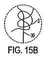
次に図5Aを参照すると、他の実施形態によるアンカ・アセンブリが、閉じ具50上への配置に適したT字アンカ・アセンブリを有している。さらに詳しくは、遠位ロッド38aが、閉じ具の先端52を通すような寸法とされた貫通孔51を備えており、閉じ具50が、ハンドル16の導入口35(図1Aを参照)を介して可撓性チューブ14を通して並進可能に挿入されている。近位ロッド38bは、閉じ具50を通す貫通穴を備えない中実のロッドであってよい。あるいは、近位ロッド38bが閉じ具を通す貫通穴を備えてもよい。好ましくは、閉じ具の先端52は、容易に組織を貫通できるように尖っている。
Referring now to FIG. 5A, an anchor assembly according to another embodiment has a T-shaped anchor assembly suitable for placement on the
図5Bに関し、ロッド38aは、ひとたび襞Fの遠位側へと押し出されると、実質的に組織の壁面Wに平行でありかつ閉じ具の長手軸に対して直角である位置へと、回転する。次いで、閉じ具50が引き込まれ、近位ロッド38bが可撓性チューブ14から押し出される。さらに詳しくは、可撓性チューブ14が組織の壁面Wから引き取られるとき、近位ロッド38bが遠位端24を通して引き出される。次いで、可撓性チューブ14から出るときに、近位ロッド38bが実質的に90°回転し、組織の壁面Wへと押し付けられる。
With reference to FIG. 5B, once the
図6Aを参照すると、さらなる実施形態によるアンカ・アセンブリ55が、図4Aに示した実施形態に類似したT字アンカ・アセンブリを有している。しかしながら、アンカ・アセンブリ55は、ロッド38aとロッド38bとの間の張力を維持するためにねじり合わせることができる微細ワイヤ綱56を含んでいる。
Referring to FIG. 6A, an
図6Bに関し、アンカ・アセンブリ55を送達する方法を説明する。最初に、遠位ロッド38aが、針34を使用して組織の両方の壁面を横切って送達される。次いで、針が遠位ロッド38aを解放すべく引き込まれ、遠位ロッド38aが組織の壁面に係合する。次に、針34が近位ロッド38bを解放すべく引き込まれ、近位ロッド38bが回転して組織の壁面に係合する。ワイヤ綱の近位部分が、押し棒42の切り欠き43(図4Bを参照)によって捕らえられており、押し棒を回転させることで、近位棒38bが組織の襞へと締め付けられる。ワイヤ綱56が押し棒42の回転によってねじられるため、組織の壁面に対して所望の力を維持することができる。
With reference to FIG. 6B, a method of delivering the
次に図7を参照すると、本発明の装置と一緒に使用するために適したアンカ・アセンブリであって、一方向に調節可能なアンカ・アセンブリが示されている。アンカ・アセンブリ60は、遠位アンカ62および一方向に調節可能な近位アンカ64を有しており、これらが縫合糸39によって接続されている。遠位アンカ62は、縫合糸39に対して並進に関して固定されている。そのような固定は、さまざまなやり方で実現可能である。例えば、図7Aに見られるように、遠位アンカ62が、一対の貫通孔63をアンカ62の中央付近に配置して備えることができ、これらの貫通孔63へと縫合糸39を通し、結び目65で結わえることができる。
Referring now to FIG. 7, there is shown an anchor assembly that is suitable for use with the apparatus of the present invention and is adjustable in one direction.
図7Bは、遠位アンカを固定するための他の技法を提示している。図7B(i)に見られるように、遠位アンカ62が、開口Oを有する中空チューブTを含むことができる。縫合糸39の遠位端が開口Oに通され、開口Oを通過できないような寸法とされた結び目Kへと形成され、遠位アンカが縫合糸に対して固定される。結び目Kの形成を容易にするため、随意により遠位アンカ62が、結び目Kが通過できるような寸法とされた遠位側開口DOを有してもよい。縫合糸39の遠位端を遠位側開口DOに通し、結び目を形成し、次いでアンカ62の中空チューブTの内側へと、開口Oに捕らえられるまで引き戻すことができる。
FIG. 7B presents another technique for securing the distal anchor. As seen in FIG. 7B (i), the
図7B(i)に関して説明した固定の技法の欠点は、開口Oに対してこすられることによって、縫合糸39が裂かれたり、あるいは切断されたりする可能性にある。図7B(ii)においては、中空チューブTが第1の端部Eを有し、第1の端部Eに、例えばニッケル‐チタニウム合金(「ニチノール」)から形成できるワイヤ環Lが接続されている。縫合糸39が、結び目Kを終端とする前に、ワイヤ環へと通されている。結び目Kは、ワイヤ環を通して引き戻すことが不可能な寸法とされている。ワイヤ環Lが、開口Oを通過する縫合糸39を案内し、開口に対する縫合糸のこすれを少なくし、縫合糸39の裂けや切断の恐れを小さくしている。
A disadvantage of the fixation technique described with respect to FIG. 7B (i) is that the
図7B(iii)は、遠位アンカを縫合糸に対して固定するためのさらに他の代案の技法を提示している。やはり遠位アンカ62が、開口Oを有する中空チューブTを有している。ロッドRがチューブTの内側に配置され、チューブの両端は、ロッドをチューブの内部に保持するため、閉じられていてもよく、ロッドRへとクリンプされていてもよい。縫合糸39の遠位端が、開口Oへと通され、ロッドRを巡って通され、開口Oの外へと戻されている。次いで、縫合糸が結び目Kにて結わえられ、遠位アンカ62を縫合糸39に対して固定している。
FIG. 7B (iii) presents yet another alternative technique for securing the distal anchor to the suture. The
図7Aおよび7Bに示した技法に加え、代案として縫合糸39を、例えばアイレットへの結び付けや適切な接着剤など、他の手段によってアンカ62に対して固定することができる。さらなる技法が、当業者にとって明らかであろう。アンカ62が、棒状またはT字のアンカとして例示されているが、それ自体は公知である種々の任意のアンカを、遠位アンカ62として使用することが可能である。典型的なアンカが、本件出願と同時に係属中である2003年7月1日付の米国特許出願第10/612,170号に記載されており、この出願は、その全体がここでの言及によって本明細書に取り入れられたものとする。さらなるアンカが、図17に関して後述される。本発明の目的において、アンカおよびアンカ・アセンブリは、組織を固定するためのクリップ、ならびに結び目および結び目の代用品を含むものと理解すべきである。さらに、アンカ・アセンブリは、当初は互いに接続されていない複数の構成部品を含むことができ、それらの構成部品を、患者の体内の処置部に集め、さらに/あるいは接続することができる。
In addition to the technique shown in FIGS. 7A and 7B, the
再び図7Aを参照すると、調節可能な近位アンカ64は、第1の端部67aおよび第2の端部67bと、第1の開口68aおよび第2の開口68bとを有する外側円筒66を有している。第1および第2の開口68は、好ましくは円筒66の中央付近に、約180°離して配置されている。さらにアンカ64は、第1の可撓性ロッド70aおよび第2の可撓性ロッド70bを、いずれも外側円筒66の内部に配置し、円筒66の第1および第2の端部67に接続して有している。ロッド70は、例えばニチノールまたはポリマーから形成でき、小さなすき間Gでお互いから隔てることができる。先のアンカ・アセンブリと同様、アンカおよび縫合糸の正確な形状、寸法、および材料は、特定の用途の必要に応じてさまざまであってよい。
Referring again to FIG. 7A, the adjustable
図7Cに最もよく見られるように、縫合糸39は、遠位アンカ62から、近位アンカ64の第1の開口68aを通り、第2の可撓性ロッド70bを巡り、第1の可撓性ロッド70aを巡り、ロッド70aおよび70bの間を通過し、第2の開口68bを通って外へと通過している。この縫合糸の引き回しが、遠位アンカ62と近位アンカ64との間に位置する縫合糸39の長さLを短縮できる一方向の調節能力を提供する。一方で、この縫合糸の引き回しは、長さLの増加を不可能にしている。図8が、この一方向の調節能力の機構を、さらに詳しく説明している。随意により、縫合糸39を、アンカ64の近位側において結び目69で結わえてもよく、これによって縫合糸の近位側ループが形成され、アンカ・アセンブリ60の配置および/または調節を容易にすることができる。
As best seen in FIG. 7C, the
図8Aにおいては、近位方向へと向かう力F1が、調整可能アンカ64の近位側で縫合糸39に加えられる一方で、アンカ64は動かぬように保持され、あるいは遠位方向へと進められる。力F1の一部が、縫合糸39を通して第2の可撓性ロッド70bへと伝えられ、ロッド70bに撓みを生じさせる。これによってすき間Gが大きくなり、縫合糸39が、ロッド70aおよび70bの間および近位アンカ64を自由に通過できるようになり、一方向の調節が容易になる。アンカ64を動かぬように保ちつつ、縫合糸39が近位側へと引き込まれる場合、遠位アンカ62がアンカ64に向かって近位側に引き込まれる。一方、アンカ64を遠位方向へと進めつつ、縫合糸39を近位方向に引き込む場合、遠位アンカ62は、近位アンカ64の遠位方向への移動の度合いに応じて、動かずにとどまり、あるいは近位アンカ64に向かって近位側へと引き込まれる。いずれにせよ、アンカ62および64の間に配置された縫合糸39の長さLは短くなり、アンカ間の長さが一方向にのみ調節される。
In FIG. 8A, a proximally directed force F 1 is applied to the
図8Bにおいては、遠位方向へと向かう力F2が、調整可能アンカ64の遠位側で縫合糸39に加えられる。力F2は、例えばアンカ62および64の間で圧縮されている組織によって、加わる可能性がある。圧縮された組織は、圧縮ばねに類似した様相でエネルギーを蓄え、一方向への締め付けの後に、アンカ62および64を引き離すように押そうとする。力F2によって、第1および第2のロッド70の周囲の縫合糸39の輪に引き締めが生じ、縫合糸39を摩擦によって第1および第2の可撓性ロッド70の間に係止するよう、両方のロッドを内向きに撓ませてすき間Gを閉じる。このようなやり方で、アンカ62および64の間の縫合糸の長さLを選択的に短縮できるが、増加させることはできない。
In FIG. 8B, a distally directed force F 2 is applied to the
当業者にとって明らかであるように、長さLを一方向に調節するために必要とされる力の大きさは、さまざまなやり方で変化させることができる。例えば、ロッド70の長さ、可撓性、または直径を変更することができる。同様に、縫合糸39の弾性または直径を変更してもよい。初期のすき間Gを増減させてもよい。またさらに、摩擦係数などの材料特性を変化させるために、ロッド70および縫合糸39の形成に使用される材料を変更することができ、さらには/あるいはロッド70または縫合糸39に、潤滑コーティングを備えてもよい。力の大きさを変化させるためのさらなる方法(そのいくつかを図9に関して後述する)が、本明細書の開示に照らして明らかであり、それらは本発明に包含される。
As will be apparent to those skilled in the art, the amount of force required to adjust the length L in one direction can be varied in various ways. For example, the length, flexibility, or diameter of the rod 70 can be changed. Similarly, the elasticity or diameter of the
次に図9を参照すると、他のアンカ64が示されている。図9Aにおいては、調節可能アンカ64’の可撓性ロッド70が、開口68に対して回転させられている(逆も然り)。図7および8に示した縫合糸の引き回しを使用するとき、ロッド70を最大180°まで時計回りに回転させることで、アンカ62および64に力が加わったときの摩擦が次第に大きくなる。図8Bに関して説明した様相で力が加わるとき、摩擦による係止の強さが大きくなる。しかしながら、図8Aに関して説明した様相で力を加えることによって近位アンカと遠位アンカとの間の縫合糸の長さを一方向に調節するときの摩擦もまた、大きくなる。ロッド70を180°を超えて時計回りに回転させると、いずれの方向の力が縫合糸39に加えられるかにかかわらず、アンカ64’が摩擦によって係止され、したがって一方向の調節能力はなくなる。ロッド70を開口68に対して反時計回りに回転させると、縫合糸39へとどちらの方向に力が加えられても、最初は摩擦は小さくなる。約90°を超えて反時計回りに回転させると、図8Bにて説明した摩擦による係止はなくなり、両方向の調節が可能になると予想される。約450°を超えて反時計回りの回転を続けると、摩擦による係止および一方向の調節の方向が反対向きになり、約720°を超える反時計回りの回転は、縫合糸39に加えられる力の方向にかかわらず、摩擦による係止をもたらす。
Referring now to FIG. 9, another
すでに述べたように、アンカ64の円筒66の開口68は、好ましくはお互いから180°離して配置される。しかしながら、一方向調節の際の摩擦を大きく増加させることなく、摩擦による係止の力を大きくするため、図9Bのアンカ64’’に見て取れるように、第1の開口68aを第2の開口68bに対して反時計回りに回転させてもよい(あるいは、その反対)。このようなやり方で、第1の開口68aはもはやロッド70に整列しておらず、一方、第2の開口68bは、依然としてロッド70に整列している。アンカ64’’に力F1が加えられるとき、第2の可撓性ロッド70bが外向きに撓むことができて、すき間Gが大きくなり、これによって一方向の調節が容易にされる。同様に、アンカに力F2が加えられるとき、すき間Gが縫合糸39へとより密に閉じられ、摩擦による係止の力が大きくなる。一方で、第1の開口68aが第2の開口に対して時計方向に回転させられるならば、摩擦による係止の力が小さくなると予想される。
As already mentioned, the openings 68 in the
図9Cにおいては、近位側の調節可能アンカ64’’’が、別の縫合糸の引き回しを有している。縫合糸39が、遠位アンカ62から、アンカ64’’’の第1の開口68aを通り、第2の可撓性ロッド70bの周囲を巡り、第1の可撓性ロッド70aの周囲を巡り、第2の可撓性ロッド70bの周囲へと戻り、ロッド70aおよび70bの間を通って、第2の開口68bを外へと通過している。図7および8のアンカ64に関して説明した縫合糸の引き回しと同様、図9Cに示した縫合糸の引き回しは、遠位アンカ62と近位アンカ64’’’との間に位置する縫合糸39の長さLの短縮を可能にする一方向の調節能力をもたらす。一方で、この縫合糸の引き回しは、長さLの増加を不可能にしている。一方向に調節が可能な縫合糸の引き回しが他にも、当業者にとって明らかであろう。
In FIG. 9C, the proximal adjustable anchor 64 '' 'has another suture routing. A
図10を参照すると、3つのロッドを有する他の一方向調節可能アンカが示されている。アンカ・アセンブリ80が、遠位アンカ62および近位アンカ82を有している。一方向に調節が可能な近位アンカ82は、第1の端部85aおよび第2の端部85b(図示されていない)と、第1の開口86aおよび第2の開口86bとを有する外側円筒84を有している。第1および第2の開口86は、好ましくは円筒84の中央付近に、約180°離して配置されている。さらにアンカ82は、第1の可撓性ロッド88a、第2の可撓性ロッド88b、および第3の可撓性ロッド88cを、すべて外側円筒66の内部に配置し、円筒64の第1および第2の端部85に接続して有している。ロッド88は、すき間G1およびG2によってお互いに離間している。
Referring to FIG. 10, another one-way adjustable anchor having three rods is shown. Anchor assembly 80 has a
縫合糸39は、遠位アンカ62から、近位アンカ82の第1の開口86aを通り、第1のロッド88aを巡り、第1のロッド88aと第2のロッド88bとの間を通り、第2のロッド88bと第3のロッド88cとの間を通り、第3のロッド88cを巡り、第1のロッド88aへと戻って第1のロッド88aを巡り、第2の開口86bを外へと通過している。図10Aに見られるように、力F1が縫合糸39に加えられると、すき間G1およびG2は開いたままであって、一方向の調節/遠位アンカ62と近位アンカ82との間に位置する縫合糸39の長さLの短縮は容易である。図10Bに見られるように、力F2が縫合糸39に加えられると、すき間G1およびG2が縫合糸39に向かって閉じられ、摩擦による係止を形成して、縫合糸39の長さLの増加を不可能にする。
The
図11を参照すると、他の3本ロッドのアンカ・アセンブリが示されている。図7〜10に関して上述した一方向調節が可能なアンカは、すべて、縫合糸を通すための開口を有する円筒の内側に、ロッドを配置している。開口は、縫合糸をロッドの中央に位置させるべく機能し、すでに述べたように、調節および摩擦係止の際に加えられる力の大きさを変化させるために使用することができる。しかしながら、このような開口は、縫合糸が開口を通して摺動するため、縫合糸の裂けまたは切断の恐れを呈する。 Referring to FIG. 11, another three rod anchor assembly is shown. All of the one-way adjustable anchors described above with respect to FIGS. 7-10 have a rod positioned inside a cylinder having an opening for threading the suture. The opening functions to position the suture in the center of the rod and can be used to change the amount of force applied during adjustment and frictional locking, as already described. However, such openings present the risk of tearing or cutting the suture as the suture slides through the opening.
図11に見られるように、アンカ・アセンブリ90は、遠位アンカ62および近位アンカ92を含んでいる。一方向に調節が可能な近位アンカ92は、第1の可撓性ロッド94aおよび第2の可撓性ロッド94b、ならびに直径が好ましくは第1および第2のロッド94よりも大きい剛体ロッド96を有している。可撓性ロッド94が、好ましくはニチノールまたはポリマーから作られる一方で、剛体ロッド96は、好ましくはステンレス鋼またはポリマーから作られる。他の材料も、当業者にとって明らかである。
As seen in FIG. 11,
さらにアンカ92は、第1の外側円筒98aおよび第2の外側円筒98bを、第1および第2のロッド94ならび剛体ロッド96の端部にクリンプして有している。クリンプする代わりに、第1および第2の円筒98がそれぞれ、ロッドが接続される端部キャップ(図示されていない)を有してもよい。第1および第2の円筒94は、アンカ92の中央部分には広がっていない。可撓性ロッド94は、すき間G1によって互いに隔てられる一方で、すき間G2によって剛体ロッド96から隔てられている。
Further, the
アンカ92は、3本のロッドを有しているが、図10のアンカ82とは異なり、縫合糸39が、そのうちの2本の周囲にのみ巻き付けられて、一方向の調節を達成している。図11Bおよび11Cに見られるように、アンカ・アセンブリ90について示されている縫合糸の引き回しは、図7および8のアンカ・アセンブリ60に関してすでに説明した引き回しに類似している。図11Aに見られるように、第1および第2の円筒98間の割れ目が、縫合糸39をロッドの中央へと位置させるように機能する一方で、剛体ロッド96が、縫合糸39を可撓性ロッド94の周囲に導くときにアンカ92を補強し、アンカ92の回転を低減する。
縫合糸39は、遠位アンカ62から近位アンカ92へと、剛体ロッド96および可撓性ロッド94の間を通り、第2の可撓性ロッド94bを巡り、第1の可撓性ロッド94aを巡り、剛体ロッド96および第1の可撓性ロッド94aの間を通り、可撓性ロッド94aおよび94bの間を通って、外へと通過する。図11Aに見られるように、力F1が縫合糸39に加えられるとき、可撓性ロッド94が引き離されてすき間G1が広がる一方で、すき間G2は実質的に一定に保たれ、遠位アンカ62と近位アンカ92との間に位置する縫合糸39の長さLを一方向に調節することが可能である。図11Bに見られるように、力F2が縫合糸39に加えられるとき、すき間G1が縫合糸39に向かって閉じられ、摩擦による係止が形成されて、縫合糸39の長さLの増加を不可能にする。すき間G2は、やはり実質的に一定のままである。
The
図12を参照すると、枢支点を有する他の一方向調節可能アンカ・アセンブリが示されている。アンカ・アセンブリ100は、遠位アンカ62および近位アンカ102を有している。一方向に調節が可能な近位アンカ102は、第1の端部104aおよび第2の端部104b(図示されていない)と、第1の開口105aおよび第2の開口105bとを有する外側円筒103を有している。第1および第2の開口105は、好ましくは円筒103の中央付近に、約180°離して配置されている。さらにアンカ102は、第1のロッドまたはパドル106aおよび第2のロッドまたはパドル106bを、いずれも外側円筒103の内部に配置し、枢支穴108を貫通するピン107によって円筒103の第1および第2の端部へと接続して有している。このようなやり方で、第1および第2のパドル106は、枢支穴108を中心として回転可能である。パドル106は、例えばステンレス鋼またはポリマーから形成でき、すき間Gでお互いから隔てられている。先のアンカ・アセンブリと同様、アンカならびに縫合糸39の正確な形状、サイズ、および材料は、特定の用途の必要に応じてさまざまであってよい。
Referring to FIG. 12, another one-way adjustable anchor assembly having a pivot point is shown.
縫合糸39は、一例として、遠位アンカ62から近位アンカ102の第1の開口105aを通り、第2のパドル106bを巡り、第1のパドル106aを巡り、パドル106aおよび106bの間を通過し、第2の開口105bを通って外へと通過している。枢支穴108を設けることによって、上述のように力F1が加えられたときに、確実にパドル106がお互いから離れるように回転してすき間Gが広げられ、一方向の調節が可能になる。同様に、すでに説明した力F2が加えられることによって、パドル106が合わさるように回転し、すき間Gが閉じられて縫合糸39がパドル間に挟まれ、摩擦によって係止される。力F2の大きさの増加は、パドル106をさらにきつく合わせるように回転させるべく機能し、したがってパドル間の縫合糸39に作用する摩擦係止の強さを、大きくするように機能する。このようなやり方で、一方向の調節が実現される。
As an example, the
次に図13を参照すると、ばね材料を有する他の一方向調節可能アンカ・アセンブリが示されている。アンカ・アセンブリ110は、遠位アンカ62および近位アンカ112を有している。一方向に調節が可能な近位アンカ112は、第1の端部114aおよび第2の端部114b(図示されていない)と、第1の開口115aおよび第2の開口115bとを有する外側円筒113を有している。第1および第2の開口115は、好ましくは円筒113の中央付近に、約180°離して配置されている。さらにアンカ112は、隙間Gによって隔てられた第1のロッド116aおよび第2のロッド116b、ならびにばね材料118を、すべて外側円筒113の内部に配置して有している。ばね材料118は、ロッド116に当接しており、ロッド116は、好ましくは実質的に円筒113と同じ長さであり、円筒113の内部で自由に移動できても、あるいは円筒113の端部(図示されていない)へと接続されていてもよい。ばね材料118も、円筒113の内部で自由に移動可能であってよく、あるいは円筒へと接続されていてもよく、直径が好ましくは縫合糸39の直径以下である管腔119を有している。ばね材料118は、例えば、圧縮可能な生体適合性の発泡体で構成でき、圧縮ばねとして機能する。
Referring now to FIG. 13, another one-way adjustable anchor assembly having a spring material is shown.
縫合糸39は、遠位アンカ62から近位アンカ112へと、円筒113の第1の開口115aを通過し、ロッド116の間を通り、ばね材料118の管腔119を通過し、第2の開口115bを外へと通過する。管腔119が、縫合糸39にぴったりと接触しており、したがって力F1が加わることによって縫合糸とばね材料との間に摩擦が生じて、ばね材料が円筒の壁面114に向かって押し付けられ、これにより、ばね材料118によってロッド116へと加えられている圧力が小さくなり、すき間Gが大きくなって、遠位アンカ62と近位アンカ102との間に位置する縫合糸39の長さLを一方向の調節を、続けることができる。力F2が加わることによってばね材料118をロッド116に対し伸ばし、これにより、ばね材料によってロッドへと加えられている圧力が大きくなり、すき間Gを閉じ、縫合糸39がロッド116の間で摩擦により係止される。
The
図14を参照すると、ワンウェイ・バルブを有する他の一方向調節可能アンカ・アセンブリが示されている。図14Aにおいて、アンカ・アセンブリ120は、遠位アンカ62および近位アンカ122を有している。一方向に調節が可能な近位アンカ122は、第1および第2の端部125aおよび125bと、第1の開口126aおよび第2の開口126bとを有する外側円筒124を有している。第1および第2の開口126は、好ましくは円筒124の中央付近に、約180°離して配置されている。さらにアンカ122は、第1の傾斜面128aおよび第2の傾斜面128bを、圧縮ばね129aおよび129bによって押し付けて有しており、これにより、2つの傾斜面の接点にワンウェイ・バルブVが形成されている。傾斜面128およびばね129は、外側円筒124の内部に配置されており、ばね129が、円筒124の端部125ならびに傾斜面の端部に当接している。縫合糸39’は、ワンウェイ・バルブVを動作させるように構成された複数の結び目またはビーズBを有している。
Referring to FIG. 14, another one-way adjustable anchor assembly having a one-way valve is shown. In FIG. 14A, the
縫合糸39’は、遠位アンカ62から近位アンカ122へと、円筒124の第1の開口126aを通過し、傾斜面128の間を通ってワンウェイ・バルブVを通過し、第2の開口126bを外へと通過している。縫合糸39’に力F1が加わると、ビーズBが傾斜面128に接触し、それらを圧縮ばね129の作用によって緩やかに引き離し、バルブVを開放してビーズがバルブを通過できるようにする。ひとたびビーズがバルブVを通過すると、ばね129が傾斜面128を並置位置へと再び押し付け、バルブを閉鎖する。力F1を加え続けると、複数のビーズがバルブを通過することができ、遠位アンカ62と近位アンカ122との間に位置する縫合糸の長さLを一方向に容易に調節することができる。力F2を加えると、縫合糸39’のビーズBが、傾斜面128の近位側に衝突する。しかしながら、ビーズによって傾斜面へと伝えられる力は、ばね129を圧縮して傾斜面128を引き離すために必要とされる方向に直角である。したがって、ビーズBが傾斜面128の近位側へと衝突しても、ワンウェイ・バルブVを開くことはできず、したがって当該バルブを通って遠位方向へと戻ることは不可能であり、これにより遠位アンカと近位アンカとの間に位置する縫合糸の長さLの一方向のみへの調節、すなわち長さLの短縮のみが、確保される。
The suture 39 'passes from the
図14Bを参照すると、ワンウェイ・バルブを有する他の一方向調節可能アンカが示されている。アンカ・アセンブリ130が、遠位アンカ62および近位アンカ132を有している。一方向に調節が可能な近位アンカ132は、ワンウェイ・バルブVを形成する傾斜面136が内部に片持ち梁式で配置されてなる管腔134を有している。複数の傾斜面139を有する「ジッパー紐」ファスナ138が、近位アンカ132と遠位アンカ62とを接続している。複数の傾斜面139は、アンカ132の傾斜面136に対して相を約180°ずらして配置されている。
Referring to FIG. 14B, another one-way adjustable anchor with a one-way valve is shown.
ファスナ138は、遠位アンカ62から近位アンカ132へと管腔134を通過し、傾斜面136の傍らを通過している。ファスナ138の傾斜面139が傾斜面136と噛合して傾斜面136を撓ませ、あるいは傾斜面136を片持ち梁の様相で変形させるため、力F1がファスナへと加えられる場合には、ファスナ138の傾斜面139が近位方向へとワンウェイ・バルブVを通過することができ、近位アンカと遠位アンカとの間に位置するファスナ138の長さLを、一方向に調節することができる。反対に、力F2がファスナへと加えられる場合には、アンカ132の傾斜面136の近位側が、ファスナ138の傾斜面139の遠位側に当接し、したがってファスナを近位アンカ132を通して遠位側へと引くことはできず、アンカ間に位置するファスナの長さLを大きく増加させることはできない。
The
図15を参照すると、引き結びを有する他の3つの一方向調節可能アンカ・アセンブリが示されている。図15Aにおいては、アンカ・アセンブリ140が、遠位アンカ142および近位アンカ144を有している。貫通孔143aおよび143bが、遠位アンカ142を貫いて延びる一方で、貫通孔145aおよび145bが、近位アンカ145を貫いて延びている。好ましくは、貫通孔143および145は、それぞれアンカ142および144の中心付近に位置している。
Referring to FIG. 15, three other one-way adjustable anchor assemblies having a knot are shown. In FIG. 15A,
縫合糸39の遠位端が、近位アンカ144の貫通孔145aを遠位アンカ142へと通過し、遠位アンカ142において貫通孔143aを通過し、貫通孔143bを通過して戻っている。さらに、縫合糸39の遠位端は、遠位アンカ142から近位アンカ144へと戻り、近位アンカの貫通孔145bを通過している。縫合糸39の遠位端は、アンカ144の近位側に位置する一方向の引き結びSに結わえられている。図15Bは、引き結びSの形成を説明する詳細図である。
The distal end of
当業者にとって明らかであるとおり、力F1が加わることによって、縫合糸39が貫通孔143および145を滑って通り、アンカ142および144の間に位置する縫合糸39の長さLが短くなる。縫合糸39は、近位方向へと引き結びSを容易に通過することができ、長さLの一方向の調節を容易にしている。一方で、力F2が加わると、引き結びSが引き締められて、縫合糸39が遠位方向へと引き結びSを通過することができないようにし、長さLの増加を不可能にする。
As will be apparent to those skilled in the art, the application of force F 1 causes the
図15Cは、アンカ・アセンブリ140の他の実施形態を示しており、引き結びが近位アンカの内部に配置されている。アンカ・アセンブリ140’は、遠位アンカ142および近位アンカ144’を有している。近位アンカ144’は、遠位開口147aおよび147bと、近位開口148とを有する中空円筒またはチューブ146を有している。
FIG. 15C shows another embodiment of the
縫合糸39の遠位端が、チューブ146の内部へと近位開口148を通過している。次いで、遠位アンカ142へと近位アンカ144’の遠位開口147aを通過し、遠位アンカ142において貫通孔143aを通過し、貫通孔143bを通過して戻っている。次に、縫合糸39は、遠位アンカ142から近位アンカ144’へと戻り、近位アンカのチューブ146の内側へと遠位開口147bを通過している。縫合糸39の遠位端が、アンカ144’のチューブ146の内部に位置する一方向の引き結びSに結わえられる。アンカ140’を、図15Aのアンカ・アセンブリ140に関して上述したやり方と同様にして、一方向に調節することができる。
The distal end of
図7〜15は、近位アンカと遠位アンカとの間の距離について一方向の調節を実現するための種々の機構を有するアンカ・アセンブリを説明している。これらの機構は、あくまで説明を分かりやすくするためだけの目的で提示されており、決して本発明を限定するものと解釈すべきではない。一方向の調節を実現するためのさらなる機構が、本明細書の開示に照らして当業者にとって明らかであり、それらは本発明に包含される。また、図7〜15のアンカ・アセンブリの大部分は、遠位アンカが縫合糸に対して固定され、近位アンカが調節可能であるものとして説明されている。しかしながら、遠位アンカが代わりに調節可能であって、近位アンカが固定されてもよく、さらには/あるいは図15のアンカ・アセンブリ140のように両方のアンカが一方向に調節可能であってもよいことを、理解すべきである。
7-15 illustrate an anchor assembly having various mechanisms for achieving unidirectional adjustment of the distance between the proximal anchor and the distal anchor. These mechanisms are presented for the purpose of clarity only and should not be construed as limiting the invention in any way. Additional mechanisms for achieving unidirectional adjustment will be apparent to those skilled in the art in light of the disclosure herein and are encompassed by the present invention. Also, most of the anchor assemblies of FIGS. 7-15 are described as having a distal anchor secured to the suture and a proximal anchor adjustable. However, the distal anchor may instead be adjustable and the proximal anchor may be fixed and / or both anchors may be adjusted in one direction, such as the
次に図16を参照すると、係止機構を有する双方向に調節可能なアンカ・アセンブリが、説明されている。アンカ・アセンブリ150が、遠位アンカ62および近位アンカ152を有している。図16Aに見られるように、双方向に調節可能な近位アンカ152が、第1の端部154aおよび第2の端部154bと、第1の開口155aおよび第2の開口155bとを有する外側円筒153を有している。第1および第2の開口155は、好ましくは円筒153の中央付近に、約90°離して配置されている。さらに近位アンカ152は、引っ張りばね158を外側円筒153の内部に配置されている。
Referring now to FIG. 16, a bi-directional adjustable anchor assembly having a locking mechanism is illustrated.
図16Bに見られるように、縫合糸39は、遠位アンカ62から近位アンカ152へと第1の開口155aを通過し、ばね158を巡り、第2の開口155bを外へと通過している。縫合糸39は、力F1または力F2が加えられる際、引っ張りばね158の周囲をいずれの方向にも自由に動くことができ、近位アンカと遠位アンカとの間に位置する縫合糸の長さLの双方向の調節を容易にしている。一方で、図16Cに見られるように、力F1およびF2が充分な大きさで同時に加わると、縫合糸39がばね158の線Tを押し広げ、線Tの間に捕らえられてその場に係止され、縫合糸の長さLのさらなる調節を不可能にする。
As seen in FIG. 16B, the
近位アンカ152の係止機構を作動させて、縫合糸39をばね158の線T内に係止するために必要とされる力の大きさは、さまざまなやり方で指定/変更することができる。例えば、外側円筒153の周囲の開口155の角度の隔たりを変化させることができ、ばね158のばね定数を指定することができ、さらには/あるいはばね158または縫合糸39に潤滑コーティングを備えることができる。他の技法も、当業者にとって明らかである。力F1およびF2の同時印加は、アンカ・アセンブリ150が組織の襞を横切って配置され、縫合糸の長さLが組織の襞を圧縮するように調節された場合に、遭遇されると予想される。そのとき、医療従事者が力F1を加える一方で、圧縮された組織の襞が、力F2を加えるであろう。
The amount of force required to actuate the locking mechanism of the
図10〜16のアンカ・アセンブリを、例証として、近位アンカの近位側に配される縫合糸またはファスナの結び目または輪(例えば、図7および8のアンカ・アセンブリ60の縫合糸39の結び目69に見られるような)がないものとして説明したが、アンカ・アセンブリの配置および/または調節を容易にするため、そのような輪または結び目を随意により設けてもよいことを、理解すべきである。さらに、上述したアンカ・アセンブリは、例証として、遠位ロッド式またはT字型のアンカを有している。しかしながら、遠位側のT字アンカが、あくまで説明を容易にするためだけの目的で提示されていることを、理解すべきである。遠位アンカ(ならびに、近位アンカ)が、例えば外科用または管腔内用クリップ、組織を固定するためのクリップ、および縫合糸の結び目または結び目の代用物など、それ自身は公知である種々の任意のアンカを含んでもよい。典型的なアンカが、本件出願と同時に係属中である2003年7月1日付の米国特許出願第10/612,170号に記載されており、この出願は、その全体がここでの言及によって本明細書に取り入れられたものとする。さらに、アンカ・アセンブリは、当初は互いに接続されていない複数の構成部品を含むことができ、それらの構成部品を、患者の体内の処置部に集め、さらに/あるいは接続することができる。さらなるアンカが、図17に関して以下で説明される。
The anchor assembly of FIGS. 10-16 is illustrated by way of example with a suture or fastener knot or ring disposed on the proximal side of the proximal anchor (eg, the knot of
図17Aを参照すると、関節アンカ160が、半円筒のベース161と、ロッド162と、縫合糸39とを有している。ロッド162は、展張位置(図7Aに示されている)と縮小形状位置(ロッド162が半円筒のベース161の内部へと枢動している)との間を、枢支点163を中心として回転(矢印164で示されているように)する。関節アンカ160を、例えば図3Eに関して上述した針34を使用して、組織の襞を貫いて送達することができる。好ましくは、関節アンカ160は、展張位置へと付勢されており、針から押し出されたときに自動的に展張する。
Referring to FIG. 17A, the
図17Bおよび17Cに関し、本発明のアンカはさらに、1つ以上の引き伸ばされた本体を、少なくとも1本の縫合糸で接続して有することができる。図17Bにおいては、アンカ165が楕円形のリング166を有しており、縫合糸39が、リングのほぼ対向する両側に取り付けられている。図17Cにおいては、アンカ168が、縫合糸39のための一対の貫通孔170を有する山形ブラケット169を有している。図17Dにおいては、アンカ171が、縫合糸39のための一対の貫通孔173を有する引き伸ばされたビーズ172を有している。これら3つのアンカ165、168、および171(ならびに、すでに述べたT字アンカ)はすべて、第2の寸法(例えば、高さ)よりも実質的に大きい第1の寸法(例えば、幅)を有している。この寸法の相違ゆえ、アンカ165、168、および171を、特定の向きで針(例えば、図3Eの針34)へと挿入する必要がある。ひとたびアンカが組織の壁面を貫いて押し出されると、縫合糸39に加わる引っ張りがアンカを回転させ、組織の壁面を通してアンカを引き戻すことができないようにする。当業者であれば理解できるとおり、他にも多数のアンカを、本発明の技術的範囲から離れることなく使用することが可能である。
With reference to FIGS. 17B and 17C, the anchors of the present invention may further have one or more stretched bodies connected by at least one suture. In FIG. 17B, the
次に図18Aを参照すると、組織の襞を形成するための装置であって、本発明の原理に従って構成された装置の他の実施形態が説明されている。装置175は、踏み車アセンブリ176を可撓性チューブ177の遠位端174に配置して有している。可撓性チューブ177は、患者の口および食道を通して、胃へと挿入されるように構成されている。踏み車アセンブリ176は、一対のハブ181aおよび181bの周囲を回転するコンベア180を有している。ハブ181aおよび181bは、それぞれ軸182aおよび182bを中心として回転し、ブラケット183によって互いに接続されている。複数の棘または針185が、コンベア180の全周を巡って実質的に規則的な間隔で配置されている。
Referring now to FIG. 18A, another embodiment of an apparatus for forming tissue folds constructed according to the principles of the present invention is described. The
可撓性チューブ177は、好ましくは、チューブの可撓性をねじり回転を可能にしたままで向上させるため、壁面を貫通する複数のスロット186を備えている。好ましくは、可撓性チューブ177は、ステンレス鋼から作られ、エッチングまたはレーザ切断によるスロット・パターンを有している。好ましくは、スロット・パターンが、チューブの長手軸に直交するスロットからなる正弦波状の繰り返しパターンである。さらなるパターンおよび/または他のパターンも、当業者にとって明らかであろう。
The
図18および19を参照すると、踏み車アセンブリ176への動力の伝達が説明されている。詳しくは、可撓性チューブ177の内側に配置された駆動軸202が、カテーテルの近位端に位置する手動ノブまたはモータに接続されている。駆動軸202の遠位端には、ベベル・ギア203が設けられており、軸182bに設けられたベベル・ギア204に噛合している。したがって、ベベル・ギア203の回転がベベル・ギア204に伝えられ、軸182bを回転させる。次いで、軸182bがハブ181bを回転させ、コンベア180を動作させる。駆動軸202の回転を逆にすると、コンベア180の方向が反転する。
18 and 19, the transmission of power to the
再び図18A〜18Dを参照し、装置175を使用して胃腸組織の襞Fを形成する方法を説明する。図18Aにおいて、可撓性チューブ177が、食道を通して、踏み車アセンブリ176が組織の壁面Wに接触するように配置される。好ましくは、接触が、組織の壁面Wに対して或る角度でなされるべきである。例えば、約45°の角度が図8Aには示されているが、他の多くの角度も、本発明の技術的範囲から離れることなく利用可能である。
Referring again to FIGS. 18A-18D, a method of forming a gastrointestinal tissue fold F using the
踏み車アセンブリ176が組織の壁面Wに接触したとき、針が遠位ハブ181aの周囲を移動するときに、針185が接触点P1において組織に係合する。図18Bに示されているように、針が遠位ハブ181aから離れるように動くとき、組織の壁面Wが近位端181bに向かって引っ張られ、組織に小さな襞Fが形成される。踏み車アセンブリが回転を続けると、次の針185が組織の壁面に係合し、組織の壁面がコンベア180の長さに沿って踏み車アセンブリ176へと堅固に拘束される。
When the
図18Cに示されているように、ひとたび組織の壁面Wが踏み車アセンブリ176へと堅固に拘束されると、可撓性チューブ177の遠位端174を、曲げ可能部位190において屈曲させて、踏み車アセンブリ176を組織の壁面Wから離れるように動かすことができる。可撓性チューブ177の屈曲は、図1の実施形態に関してすでに説明したように、カテーテルの近位端に配置された制御ワイヤおよびアクチュエータを使用して達成できる、踏み車アセンブリを組織の壁面Wから離れるように動かすことで、さらなる組織が近位方向へと引っ張られ、組織の襞Fが引き延ばされる。
As shown in FIG. 18C, once the tissue wall W is firmly constrained to the
図18Dにおいて、組織の襞Fが、可撓性チューブ177の曲げ可能部位190を横切って引き延ばされ、接触点P2が形成される。これにより、尖った針または閉じ具を、曲げ可能部位190のスロット186のうちの1つを通し、組織の壁面Wの4つの層すべてを横断して延伸させることができる。好都合なことに、曲げ可能部位190を横切って組織の襞Fを引き伸ばすことで、アンカを筋肉層および漿膜層の両者を貫いて打ち出すことができ、胃腸組織の近接のための耐久性に富んだ基礎がもたらされる。例えば、針192を、曲げ可能部位190のスロット186を通し、組織の襞Fの根元部分を通して延伸させることができ、アンカ・アセンブリ(図4〜17のいずれかに関して説明したような)を、針192から打ち出して襞を固定することができる。あるいは、閉じ具(図5Aおよび5Bに関して説明したような)を、接触点P2において組織の襞を貫いて、アンカ・アセンブリを送達するために使用することができる。踏み車アセンブリ176を、近位ハブ181bの回転を逆にすることによって、組織の壁面Wから切り離すことができる。
In FIG. 18D, tissue fold F is stretched across
次に図20Aを参照して、組織の襞を形成するための装置であって、本発明の原理に従って構成されている装置のさらに他の実施形態を説明する。装置200は、図18の実施形態に関して説明したような可撓性チューブ177’の遠位端に、組織把持アセンブリ18’を接続して有している。可撓性チューブ177’は、好ましくは、ねじり回転を可能にしたままでチューブの可撓性を向上させるため、壁面を貫通する複数のスロット186’を備えている。さらには、可撓性チューブ177’を、ステンレス鋼から製作でき、例えばチューブの長手軸に直交するスロットからなる正弦波状の繰り返しパターンなど、エッチングまたはレーザ切断によるスロット・パターンを備えることができる。他の可撓性化パターンも、明らかであろう。
Referring now to FIG. 20A, yet another embodiment of an apparatus for forming tissue folds constructed according to the principles of the present invention will be described.
組織把持アセンブリ18’は、図1の実施形態に関して説明した組織把持アセンブリに類似しており、一対の顎28a’、28b’を、枢支点29’を中心として開放状態と閉鎖状態との間で回転させるように配置して有している。顎28a’および28b’のそれぞれは、好ましくは、組織の壁面Wを容易に把持することができるよう、尖った歯33’を遠位端の付近に配置して備えている。
Tissue grasping assembly 18 'is similar to the tissue grasping assembly described with respect to the embodiment of FIG. 1 and includes a pair of
図20Aに関し、組織把持アセンブリ18’が、食道を通して組織の壁面Wの付近に配置され、顎28a’、28b’が、開放位置へと動かされている。次いで、組織把持アセンブリ18’が、組織の壁面Wに接触するように動かされる。図20Bに示すように、組織把持アセンブリ18’が、第1の接触点P1において組織の壁面を把持すべく使用される。組織の壁面Wの一部分を顎28a’、28b’の内側に捕らえた後、可撓性チューブ177’が近位方向へと動かされ、組織の壁面Wが引き伸ばされて組織の襞Fが形成される。
With reference to FIG. 20A, a tissue grasping assembly 18 'has been placed through the esophagus in the vicinity of the tissue wall W and the
図20Cを参照すると、組織の襞Fが形成された後、可撓性チューブ177’の遠位端が曲げ可能部位190’のあたりで屈曲し、組織把持アセンブリ18’を組織の壁面Wから離れるように移動させる。可撓性チューブ177’の屈曲を、カテーテルの近位端に配置されたアクチュエータを使用して制御することができ、組織の襞Fを引き伸ばすことができる。
Referring to FIG. 20C, after the tissue fold F is formed, the distal end of the
図20Dにおいて、組織の襞Fが、曲げ可能部位190’を横切って引き伸ばされており、したがって尖った針または閉じ具を、曲げ可能部位190’のスロット186’のうちの1つから、組織の壁面Wの4つの層すべてを横断して延伸させることができる。次いで、針192’を、曲げ可能部位190’のスロット186’から、接触点P2および組織の襞Fを通して延伸させることができる。次いで、アンカ・アセンブリ(例えば、図4〜17のいずれかに関して説明したような)を、針192’から打ち出して襞を固定することができる。あるいは、閉じ具(例えば、図5Aおよび5Bに関して説明したような)を、接触点P2において組織の襞を貫いて、アンカ・アセンブリを送達するために使用することができる。
In FIG. 20D, the tissue fold F has been stretched across the
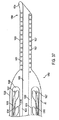
次に図21を参照し、図7〜17の調節可能アンカ・アセンブリと一緒に使用するように構成されたアンカ送達システムを説明する。図21には、アンカ送達システムが、図7のアンカ・アセンブリ60と一緒に使用されて例示されているが、これを決して本発明を限定するものと解釈してはならない。また、組織の襞を固定するために、図21の送達システムを、上述の装置10、175、200や後述の他の装置など、組織の襞を形成するための装置と組み合わせて使用することができる。あるいは、この送達システムを、アンカ・アセンブリの送達を必要とする他の任意の用途に使用することができ、あるいはアンカ・アセンブリの送達を必要とする他の任意の装置と組み合わせて使用することができる。
Referring now to FIG. 21, an anchor delivery system configured for use with the adjustable anchor assembly of FIGS. Although FIG. 21 illustrates an anchor delivery system used in conjunction with the
図21Aにおいて、アンカ送達システム250の遠位領域が、組織の壁面Wの組織の襞Fの付近に配置されている。アンカ送達システム250は、管腔253を有する可撓性送達チューブ252を有している。可撓性送達チューブ252を、患者の口および食道を通して胃などの胃腸管腔へと送達されるように構成できる。送達チューブ252の管腔253は、好ましくは約5mm未満の直径を有し、さらに好ましくは、約2〜3mmの直径を有している。可撓性送達チューブ252は、好ましくは、ねじり回転を可能にしたままでチューブの可撓性を向上させるため、壁面を貫通する複数のスロット254を備えている。スロット254によって、曲げ可能部位255を形成することができる。好ましくは、可撓性送達チューブ252は、ステンレス鋼から作られ、エッチングまたはレーザ切断によるスロット・パターンを有している。好ましくは、スロット・パターンが、チューブの長手軸に直交するスロットからなる正弦波状の繰り返しパターンである。さらなるパターンおよび/または他のパターンも、明らかであろう。
In FIG. 21A, the distal region of
さらに、アンカ送達システム250は、送達針260を有している。針260の長さは、好ましくは2cm未満であり、さらに好ましくは1.5cmである。針260は、好ましくは、尖った遠位端262、管腔264、遠位端262から近位方向に延びるスロット266、および近位側のアイレット268を有している。
In addition, the
針260の管腔264は、内部に遠位アンカを配置できる寸法とされている。すでに述べたように、アンカ送達システム250は、図7のアンカ・アセンブリ60との組み合わせで例示されている。図21Aにおいて、遠位アンカ62が、針260の管腔264の内側に配置されている。遠位アンカ62から近位アンカ64へと延びる縫合糸39が、針のスロット266を通過している。針260が、好ましくは、曲げ可能部位255の遠位側において可撓性送達チューブ252の管腔253内に配置される一方で、近位アンカ64は、好ましくは、曲げ可能部位255の近位側において送達チューブ252内に配置されている。
The
この構成においては、例えばアンカ送達システム250が上述の襞形成システムとの組み合わせにおいて使用される場合などに、曲げ可能部位を動作すなわち屈曲させつつ、遠位アンカ62を針260によって展張できる。続いて近位アンカ64を、曲げ可能部位を再び真っ直ぐにした後に、曲げ可能部位255を通過して前進させることができる。曲げ可能部位の遠位側に位置する遠位アンカ62と、曲げ可能部位の近位側に位置する近位アンカ64との間を延びる縫合糸39の距離、すなわち長さは、好ましくは約2cm以上であり、さらに好ましくは4cm以上である。
In this configuration, the
針260は、可撓性送達チューブ252の遠位端を超えての針の移動を容易にするため、近位側において針押し棒270に接続されている。針押し棒270は、アンカ送達システム250の近位端に位置する制御アクチュエータ(図示されていない)まで延びている。押し棒270は、例えば組織の壁面Wの穿孔および針260の組織の襞Fの通過を容易にするため、随意により、ばね(図示されていない)で付勢されてもよい。
さらにアンカ送達システム250は、針260のアイレット268を通して着脱可能に配置され、針260の管腔264から遠位アンカ62を押し出すように構成されているアンカ押し棒280を有している。針押し棒270と同様、アンカ押し棒280も、アンカ送達システム250の近位端に位置する制御アクチュエータ(図示されていない)まで延びている。押し棒270および280を制御するアクチュエータは、必要に応じて2つの押し棒間の相対運動を制限および/または排除できるよう、好ましくは少なくとも部分的に接続されている。押し棒280が、縫合糸39の結び目69によって形成された縫合糸の近位側のループを通過しており、縫合糸のループが、針押し棒270とアンカ押し棒280との間に通されている。これが、後述のように、遠位アンカ62と近位アンカ64との間に位置する縫合糸の長さの一方向への調節を容易にする。
図21Bにおいて、押し棒270および280が同時に、例えばばねの荷重による充分な力で遠位方向へと進められ、結果として、針260の尖った遠位端262が組織の壁面Wを貫通し、襞Fを面向いて前進する。針を前進させる際、襞形成装置に関して上述(図3Eを参照)したように、可撓性送達チューブ252の曲げ可能部位255を、随意により屈曲させてもよい。次いで、図21Cに見られるように。アンカ押し棒280が、針押し棒270および針260に対して遠位方向に進められ、遠位アンカ62に当接して、このアンカを針260の管腔264から組織の襞Fの遠位側へと押し出す。縫合糸39も、同様にスロット266から追い出され、襞Fを貫いて配置される。
In FIG. 21B, push
送達の際には、遠位アンカ62の長手軸は、針260の長手軸に実質的に平行である。しかしながら、ひとたびアンカ62が針260から押し出されると、縫合糸の張力がアンカに、アンカの長手軸を中心とする約90°の回転を生じさせ、アンカの長手軸が、針260の長手軸に実質的に直交するようになる。この遠位アンカ62の回転によって、遠位アンカが組織の壁面Wを通して引き戻されることがないようにされる。組織の壁面に接触したときにそのような回転を促進するため、アンカ62の一端または両端に、外向きのフレア(図示されていない)を設けてもよい。
Upon delivery, the longitudinal axis of the
図21Dにおいては、アンカ押し棒280が、針260の管腔264内において近位側に引き戻され、針が、押し棒270によって可撓性送達チューブ252の内部へと引き戻され、さらに送達システム250が、組織の襞Fを横切って近位側へと引き戻されている。遠位アンカ62が、組織の襞に遠位側に位置し、縫合糸39が、襞を通過して延び、近位アンカ64が、送達チューブ252の内側で襞の近位側に位置している。遠位アンカ62の配置の際に曲げ可能部位255が曲げられている(図3Eを参照)場合、近位アンカの送達を容易にするため、真っ直ぐにされる。
In FIG. 21D, the
次いで、送達チューブ252が押し棒270および280に対して近位方向に引き込まれ、これによって針260が、組織の襞Fの近位側において送達チューブの管腔253から出て、近位アンカ64が管腔から出るための空間がもたらされる。次に、送達チューブ252または送達システム250の全体が引き戻され、図21Eに見られるように、近位アンカ64が送達チューブの管腔253から追い出される。次いで、送達チューブ252が再び進められ、さらに/あるいは押し棒270および280が同時に引き込まれ、針260が再び送達チューブの管腔253の内側に配置される。
The
可撓性送達チューブ252が、近位アンカ64を遠位方向へと押すように、針260に対して進められる。図21Fに見られるように、縫合糸39の結び目69によって形成された近位側の縫合糸のループが、針260の近位端およびアンカ押し棒280に引っ掛かり、遠位アンカ62を組織の襞Fに対してぴったりと引き寄せる。送達チューブ252の前進を続けることによって、近位アンカ64を組織の襞に向かって押し付けつつ、遠位アンカ62と近位アンカ64との間に位置する縫合糸39の長さLが一方向に調節、すなわち短縮され、襞が近位アンカと遠位アンカとの間にしっかりと固定される。
The
ひとたび長さLが、アンカ・アセンブリ60によって組織の襞Fが所定の位置に堅固に固定されるように調節されると、アンカ押し棒280を針押し棒270および針260に対して近位方向に引き込むことができ、アンカ押し棒280の遠位端が、アイレット268を通って針260から出るように近位側に引き込まれる。図21Gに見られるように、縫合糸39の結び目69によって形成された縫合糸のループが、アンカ押し棒280の遠位端から滑り落ち、アンカ・アセンブリ60がアンカ送達システム250から離れる。次いで、アンカ送達システム250を、患者から取り去ることができる。あるいは、針260、針押し棒270、およびアンカ押し棒280を近位側へと引き込んで、アンカ送達チューブ252の管腔253から取り出してもよい。次いで、さらなるアンカ・アセンブリ60を、送達チューブの遠位端を患者の体内に残しつつ送達チューブの近位端から、針260および送達チューブ252の内部に装填することができる。このさらなるアンカ・アセンブリを、例えばさらなる組織の襞を貫いて配置することができる。
Once the length L is adjusted by the
送達システム250は、随意により、調節の後で縫合糸のうちの近位アンカ64から近位側へと延びている部位を除去するための切断装置(図示されていない)を有することができる。あるいは、そのような縫合糸の近位部分の長さを除去するため、補助的な装置を設けてもよい。さらに他の代案としては、縫合糸の不要な長さを、術後も患者の体内に残してもよい。
The
アンカ・アセンブリ60の配置および調節に必要とされる工程の数を減らすため、ひとたび図21Cのように遠位アンカ62が配置されると、アンカ送達システム250の全体を、針260が送達チューブの管腔253の外部に位置したままで組織の襞Fを横切って引き戻されるよう、近位側へと引き込むことができる。これは、針が組織の襞を横切っての引き戻しに先立って送達チューブの内側に配置される図21Dに関して説明した方法と、対照的である。アンカ送達システム250または送達チューブ252の近位方向への引き込みを続けることで、近位アンカ64が送達チューブの管腔253から配置される。次いで、アンカ・アセンブリ60を、すでに説明したとおり一方向に調節することができる。
To reduce the number of steps required to position and adjust the
好都合なことに、アンカ送達システム250は、アンカ・アセンブリの配置のすべての工程において、医療従事者に大きな制御の余地を提供する。そのような制御は、医療従事者に、アンカ・アセンブリの配置を中止する充分な機会を与える。図21Bに見られるように針260が組織の襞Fを貫いて通過した後に、医療従事者は、遠位アンカを押し出すことなく、針を襞を横切って引き戻すように決定することができる。あるいは、図21Dに見られるように遠位アンカ62を配置した後に、医療従事者は、近位アンカを配置せずに、近位アンカと遠位アンカとを接続している縫合糸を切断することを選択できる。その結果、遠位アンカは、単に患者の消化系を害なく通過するであろう。さらに他の例としては、医療従事者が、配置後の近位アンカおよび遠位アンカを引き締めず、組織の襞Fを固定することなくアンカをその場に残すことを選択できる。またさらに、医療従事者は、引き締めを元に戻し、あるいは配置後のアンカ・アセンブリを切断することで、組織の襞の形成を破棄することができる。
Advantageously, the
当業者にとって明らかなように、アンカ送達システム250が、上述の装置10、175、または200との組み合わせにおいて、これら装置によって形成された襞Fを貫いてアンカ・アセンブリを配置するために使用されるとき、可撓性送達チューブ252は、装置10、175、または200のそれぞれの可撓性チューブ14、177、または177’で構成されてよく、あるいはこれらの可撓性チューブ14、177、または177’を通して進められてもよい。同様に、針260が、装置10、175、または200のそれぞれの針34、92、または92’で構成されてもよい。あるいは、針260が図5の閉じ具50で構成されてもよい。言うまでもないが、アンカ送達システム250の各構成部品は、後述される他の組織用襞形成装置の相応する構成部品で構成されてもよく、あるいはそのような構成部品を通して進められてもよい。
As will be apparent to those skilled in the art,
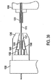
次に図22を参照し、他のアンカ送達システムを説明する。図21のアンカ送達システム250と同様、図22のアンカ送達システム300は、図7〜17の調節可能アンカ・アセンブリと一緒に使用すべく構成されている。図22においては、アンカ送達システム300が、図7のアンカ・アセンブリ60と一緒に使用されて例示されているが、これを決して本発明を限定するものと解釈してはならない。また、組織の襞を固定するために、送達システム300を、上述の装置10、175、200や後述する他の装置など、組織の襞を形成するための装置と組み合わせて使用することができる。あるいは、この送達システムを、アンカ・アセンブリの送達を必要とする他の任意の用途に使用することができ、あるいはアンカ・アセンブリの送達を必要とする他の任意の装置と組み合わせて使用することができる。
With reference now to FIG. 22, another anchor delivery system is described. Similar to anchor
図22Aは、アンカ送達システム300の遠位領域を示している。システム300は、管腔303を有する可撓性送達チューブ302を有している。可撓性送達チューブ302を、患者の口および食道を通して胃などの胃腸管腔へと送達されるように構成できる。可撓性送達チューブ302は、好ましくは、ねじり回転を可能にしたままでチューブの可撓性を向上させるため、壁面を貫通する複数のスロット304を備えている。スロット304によって、曲げ可能部位305を形成することができる。好ましくは、可撓性送達チューブ302は、ステンレス鋼から作られ、エッチングまたはレーザ切断によるスロット・パターンを有している。好ましくは、スロット・パターンが、チューブの長手軸に直交するスロットからなる正弦波状の繰り返しパターンである。さらなるパターン/他のパターンも、当業者にとって明らかであろう。
FIG. 22A shows the distal region of
さらに、可撓性送達チューブ302は、管腔または穴308を有するアンカ・チューブ307へと接続された端部領域306を有している。図22Bに最もよく見て取れるように、アンカ・チューブ307の管腔308が、貫通スロット309によって送達チューブ302の管腔303に連絡している。近位アンカ64がアンカ・チューブ307の内部に配置される一方で、遠位アンカ62が、送達チューブ302の内部に位置する針260’の内側に配置されている。
In addition, the
縫合糸39は、スロット266’を通って遠位アンカ62から針260’の外へと通過している。次いで、貫通スロット309を介して可撓性送達チューブ302からアンカ・チューブ307へと渡っている。近位アンカ64を通過した後、縫合糸39は貫通スロットを通って送達チューブ302へと戻り、縫合糸39の結び目69によって形成された縫合糸のループが押し棒280’の間に配置されるように、アンカ押し棒280’に通されている。
針260’、針押し棒270’、およびアンカ針押し棒270’、ならびにアンカ押し棒280’は、押し棒270であり、それぞれ図21のアンカ送達システム250に関して説明した針260および280と実質的に同一である。さらに、アンカ・アセンブリ60を、システム250に関して上述したやり方と同様のやり方で、アンカ送達システム300から送達し、アンカ送達システム300によって調節することができる。
図22Aにおいて、アンカ送達システム300のアンカ・チューブ307が、内部に近位アンカ64を配置するように構成された管腔または穴308を有する比較的短いチューブとして例示されている。しかしながら、代案として、アンカ・チューブ307、管腔308、および/または貫通スロット309が、送達システム300の可撓性送達チューブ302の近位端までのすべてにわたって延びてもよく、あるいはその一部分にわたって延びてもよいことを、理解すべきである。好都合なことに、そのような構成は、例えばアンカ送達システム300の遠位領域を患者の体内に配置したままでアンカ送達システム300への再装填を行うために、アンカ・アセンブリ60をアンカ送達システムの近位端から容易に装填できるようにする。さらに、そのような構成は、システムの製造を簡単にする。
In FIG. 22A, the
アンカ送達システム300を、内部にアンカ・アセンブリ60が1つだけ配置されるものとして例示した。しかしながら、送達システム300に複数のアンカ・アセンブリを装填することで、組織の襞の種々の点を貫き、異なる(例えば、隣り合う)組織の襞を貫き、あるいは他の組織構造を貫いての複数のアンカ・アセンブリの挿入を容易にできることを、理解すべきである。複数の遠位アンカ62が、好ましくは、可撓性挿入チューブ302の針262’の内側に装填される一方で、複数の近位アンカ64が、好ましくは、アンカ・チューブ307の管腔308内に装填される。
The
図21のシステム250と比べたとき、アンカ送達システム300の利点は、近位アンカおよび遠位アンカの両者が、送達の際に送達チューブの曲げ可能部位の遠位側に位置している点にある。これにより、アンカ間に位置しなければならない縫合糸の初期の長さを短くでき、送達および調節の後に近位アンカの近位側へと延びる不要な縫合糸の長さを短くすることができる。さらに、送達チューブの曲げ可能部位を曲げたままで、近位アンカおよび遠位アンカの両者を送達できるため、送達が簡潔にできる。さらには、近位アンカを別個のアンカ・チューブに配置することで、近位アンカを配置すべく組織の襞の近位側で針を可撓性送達チューブから押し出す必要がなくなり、針で誤って組織に孔を空けてしまう恐れが少なくなる。
Compared to
図23を参照し、代案となる他のアンカ送達システムを説明する。図21および22のそれぞれのアンカ送達システム250および300と同様、図23のアンカ送達システム400は、図7〜17の調節可能アンカ・アセンブリと一緒に使用すべく構成されている。アンカ送達システム400が、図7のアンカ・アセンブリ60と一緒に使用されて例示されているが、これを決して本発明を限定するものと解釈してはならない。また、組織の襞を固定するために、送達システム400を、上述の装置10、175、200や後述する他の装置など、組織の襞を形成するための装置と組み合わせて使用することができる。あるいは、この送達システム400を、アンカ・アセンブリの送達を必要とする他の任意の用途に使用することができ、あるいはアンカ・アセンブリの送達を必要とする他の任意の装置と組み合わせて使用することができる。
With reference to FIG. 23, another alternative anchor delivery system will be described. Similar to anchor
図23は、アンカ送達システム400の遠位領域を示している。システム400は、管腔403を有する可撓性送達チューブ402を有している。可撓性送達チューブ402を、患者の口および食道を通して胃などの胃腸管腔へと送達されるように構成できる。可撓性送達チューブ402は、好ましくは、ねじり回転を可能にしたままでチューブの可撓性を向上させるため、壁面を貫通する複数のスロットを備えている。スロットによって、曲げ可能部位405を形成することができる。
FIG. 23 shows the distal region of the
さらに、アンカ送達システム400は、送達時に曲げ可能部位405の遠位側において可撓性送達チューブ402の管腔内403に位置する挿入針260’’を有している。すでに述べたように、アンカ送達システム400は、図7のアンカ・アセンブリ60と組み合わせて例示されている。針260’’は、好ましくは、アンカ・アセンブリ60の遠位アンカ62および近位アンカ64を内部に配置するための充分な長さを有しており、例えば針260’’の長さは、約5cm未満であり、さらに好ましくは約3cmである。長さが増やされている点を除き、針260’’は、図21の針260と実質的に同一である。
In addition, the
図23においては、遠位アンカ62および近位アンカ64の両方が、針260’’の管腔264’’に配置されている。縫合糸39は、遠位アンカ62から近位アンカ64へと延びるとき、針のスロット266’’を通過し、再び通過している。あるいは、挿入の際、近位アンカと遠位アンカとの間の縫合糸の長さを、針の内部に位置させてもよい。好都合なことに、例えばアンカ送達システム400をすでに述べた襞形成装置と組み合わせて使用するときに、アンカ・アセンブリ60の近位アンカおよび遠位アンカの両者を、曲げ可能部位405を動作すなわち屈曲させたままで、針260’’を通して配置することができる。
In FIG. 23, both the
針260’’は、近位側において可撓性針押しチューブ420に接続されており、可撓性針押しチューブ420によって、針を可撓性挿入チューブ402の遠位端の向こうへと容易に平行移動させることができる。当業者にとって明らかであるように、針260’’および針押しチューブ420を、随意により、単一の部品として製造してもよい。針押しチューブ420は、管腔422ならびに管腔422につながるスカイブ424を有している。針押しチューブ420は、アンカ送達システム400の近位端に位置する制御アクチュエータ(図示されていない)に接続されている。制御アクチュエータは、ばねによって付勢されていてもよい。
Needle 260 '' is connected proximally to flexible
すでに説明したアンカ押し棒280と実質的に同一であるアンカ押し棒280’’が、スカイブ424の遠位側において針押しチューブ420の管腔422内に、着脱可能に配置されている。押しチューブ420と同様、アンカ押し棒280’’も、アンカ送達システムの近位端に位置する制御アクチュエータ(図示されていない)まで延びている。縫合糸39が、近位方向へと、近位アンカ64から針260’’のスロット266’’を通り、スカイブ424を通って針押しチューブ420の管腔422の内部に延び、アンカ押し棒280’’を巡り、スカイブ424を外へと通過して結び目69まで延びている。結び目69によって形成される縫合糸の近位側のループが、押し棒280’’の周囲かつ針押しチューブの管腔422内に捕らえられているため、遠位アンカ62と近位アンカ64との間に位置する縫合糸の長さを、一方向に容易に調節することができる。縫合糸の近位側のループの代案として、縫合糸39の近位端に結び目69を形成して、この結び目がアンカ押しチューブ280’’と針押し棒420との間に捕らえられるようにしてもよい(図24の結び目Kを参照)。
An
アンカ送達システム400によってアンカ・アセンブリ60を、いくつか変更点はあるが図21のアンカ送達システム250に関して上述したやり方と同様のやり方で、送達、配置、および調節することができる。具体的には、遠位アンカ62の配置の際に、アンカ押し棒280’’が近位アンカ64に当接して進められ、次いで近位アンカ64が、直列にある遠位アンカ62を前進させる。押し棒は、遠位アンカを針の管腔264’’から押し出すために充分な距離だけ、針260’’に対して進められ、時期尚早に近位アンカ64が押し出されてしまうほどには、進められない。遠位アンカが時期尚早に押し出されてしまうことがないようにするため、動きを制限する装置を設けてもよい。典型的な動き制御装置が、図24に関して後述されるが、それ自身は公知であるさらなる装置も、明らかである。
近位アンカ64を針260’’の管腔264’’から押し出すために、近位アンカと遠位アンカとの間に位置する縫合糸39の長さLが引き張られて近位アンカが針の管腔から引き出されるまで、針が引き込まれ、あるいはアンカ押し棒280’’が、近位アンカを管腔から押し出すために充分な距離だけ、針260’’の管腔内を進められる(あるいは、これらを組み合わせてもよい)。さらに、送達および調節の後にアンカ・アセンブリ60をアンカ送達システム400から解放するため、結び目69によって形成された縫合糸39のループがもはや針押し棒420の管腔422内に捕らえられなくなるよう、アンカ押し棒280’’がスカイブ424の近位側まで引き込まれる。アンカ・アセンブリ60を配置した後、送達システム400を患者の体内から取り去ることができる。あるいは、送達チューブ402を患者から取り去る必要なくさらなるアンカを配置できるよう、針260’’および針押し棒420ならびにアンカ押し棒280’’を患者から取り去り、新しいアンカ・アセンブリを装填し、可撓性送達チューブ402を通して前進させてもよい。
To push the
図21のシステム250と比べたとき、アンカ送達システム400の大きな利点は、近位アンカおよび遠位アンカの両者が、可撓性送達チューブ402の曲げ可能部位405の遠位側に位置している点にある。図22のシステム300と比べたとき、アンカ送達システム400の大きな利点は、近位アンカおよび遠位アンカの両者が針260’’の内側に配置され、アンカ・チューブの必要をなくすとともに、システムの外寸を小さくしている点にある。
Compared to the
次に図24を参照し、動き制限装置を有しているアンカ送達システム400の他の実施形態を説明する。アンカ送達システム400’は、針押し棒420’が、どちらも針押し棒の管腔422’に連絡している動き制限スカイブ430および一方向調節スカイブ432という2つのスカイブを有する点を除き、システム400と実質的に同一である。縫合糸39が、近位アンカ64から近位方向に向かい、動き制限スカイブ430を通り、アンカ押し棒280’’と針押しチューブ420’との間の管腔422’内に延びている。縫合糸39は、スカイブ430を出て、アンカ押し棒280’’によってスカイブ430に捕らえられる動き制限用の結び目Kで結わえられている。その後、縫合糸39は、一方向調節スカイブ432、および結び目69によって形成され押し棒280’’の周囲でスカイブ432に捕らえられる縫合糸の近位側ループまで、近位方向に続いている。
Referring now to FIG. 24, another embodiment of an
近位アンカ64と結び目Kとの間を延びる縫合糸の長さは、遠位アンカ62が針260’’の管腔264’’から出ることができるが、結び目Kがアンカ押し棒280’’によってスカイブ430に捕らえられている間は、近位アンカ64が出ることができないように指定される。例えば、組織の襞を貫いてアンカ・アセンブリ60を送達する際、押し棒280’’の前進によって近位アンカ64が進められ、次いで近位アンカ64が、整列している遠位アンカ62を、組織の襞の遠位側において針の管腔264’’から追い出されるまで前進させる。結び目Kが、アンカ押し棒280’’の前進可能距離を制限し、近位アンカ64が時期尚早にも配置されてしまうことがないようにする。
The length of the suture extending between the
アンカ送達システム400’が再び組織の襞の近位側へと配置されると、アンカ押し棒280’’が、動き制限スカイブ430の近位側へと引き込まれ、結び目Kがスカイブ430から逃げ出すことができるようになって、近位アンカ64の配置が容易にされる。近位アンカ64を、2つのアンカ間の縫合糸の長さが引き張られて近位アンカが針から引き出されるまで、針260’’を引き込むことによって、あるいはアンカ押し棒280’’を再び前進させて近位アンカを針から押し出すことによって、配置することができる。
When the
次いで、アンカ・アセンブリを、すでに述べたように、スカイブ232に捕らえられた縫合糸のループによって、一方向に調節することができる。調節が完了した後、アンカ押し棒280’’が一方向調節スカイブ432の近位側まで引き込まれ、縫合糸39の結び目69によって形成されている縫合糸のループが、スカイブ432から逃げることができるようになる。すでに述べたアンカ送達システム250および400と同様、アンカ・アセンブリを配置した後に、システム400’を患者の体内から取り去ることができ、あるいは可撓性チューブ402を患者の体内に残しつつ再装填を行うことができる。図23のシステム400と比べたとき、アンカ送達システム400’の大きな利点は、動き制限スカイブ430が近位アンカ64を時期尚早に配置してしまう恐れを少なくする点にある。
The anchor assembly can then be adjusted in one direction by a suture loop trapped in the skive 232 as previously described. After the adjustment is complete, the
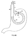
図25を参照し、代案となるさらに他のアンカ送達システムを説明する。アンカ送達システム500は、複数の調節可能アンカ・アセンブリを、再装填または患者からの取り出しを必要とすることなく送達できるように構成されている。送達システム500は、組織の襞を形成するための装置と組み合わせて使用することが可能であり、アンカ・アセンブリの送達を必要とする他の任意の用途に使用することができ、あるいはアンカ・アセンブリの送達を必要とする他の任意の装置と組み合わせて使用することができる。図25においては、アンカ送達システム500に、複数の図7のアンカ・アセンブリ60が装填されて例示されているが、これを決して本発明を限定するものと解釈してはならない。
With reference to FIG. 25, yet another alternative anchor delivery system will be described.
図25は、アンカ送達システム500の遠位領域を示している。システム500は、可撓性送達チューブ510、可撓性針チューブ520、アンカ押し棒530、およびスカイブ棒540を有している。送達チューブ510は、上述の送達チューブ402と実質的に同一であるが、管腔511および随意による曲げ可能部位512を有している。針チューブ520は、送達針522、アンカ管腔523、およびスカイブ穴524を有している。管腔523は、針チューブ520の近位端から針522まで針チューブ520を通って延びており、管腔内に、アンカ押し棒530ならびにアンカ・アセンブリ60が配置されている。穴524は、好ましくは、針522の直ぐ近位側を終端としており、穴内にスカイブ棒540が配置されている。製造を容易にするため、随意により穴524を、針522まで全体にわたって延びる管腔(図示されていない)で置き換えてもよい。
FIG. 25 shows the distal region of
さらに、針チューブ520は、第1の動き制限貫通スロット526a、第1の一方向調節スカイブ528a、第2の動き制限貫通スロット526b、および第2の一方向調節スカイブ528bという2つの貫通孔および2つのスカイブを有している。スカイブおよび貫通スロットは、すべてスカイブ穴524に連絡している。さらに、貫通スロット526は、アンカ管腔523に連絡しており、アンカ管腔とスカイブ穴524の間の通路を提供している。さらに、スカイブ528は、針チューブ520の外側に連絡しており、外部とスカイブ穴524との間の通路を提供している。
Further, the
すでに述べたように、アンカ送達システム500は、アンカ・アセンブリ60が装填されて例示されている。第1のアンカ・アセンブリ60aおよび第2のアンカ・アセンブリ60bが、アンカ管腔523の内部に配置され、アセンブリ60aがアセンブリ60bの遠位にある。アンカ押し棒530が、管腔523内で第2のアセンブリ60bの近位側に位置している。
As already mentioned, the
第1のアンカ・アセンブリ60aの第1の縫合糸39aは、管腔523内を近位方向に、第1の遠位アンカ62aから第1の近位アンカ64aへと延び、第1の近位アンカ64aを通過して延びている。次いで、縫合糸39aは、アンカ管腔523からスカイブ穴524へと第1の動き制限貫通スロット526aを経由して延びている。縫合糸39aは、スカイブ棒540を緩く囲み、第1の動き制限用の結び目K1Aにて自分自身に結わえられており、結び目K1Aによって形成された縫合糸のループが、スカイブ棒540の周囲に捕らえられている。第1の近位アンカ64aと第1の動き制限用の結び目K1Aとの間に位置する縫合糸の長さは、第1の遠位アンカ62aを針チューブ520の管腔523から繰り出すことができるように充分長いが、管腔からの第1の近位アンカ64aの繰り出しを可能にするほどには長くない。むしろ、縫合糸のこの長さが、結び目Kamによって形成されたループで引き張られ、第1の貫通スロット526aに当接してスカイブ棒540の周囲に捕らえられる。このようにして、結び目K1Aによって形成された縫合糸のループが、スカイブ棒540に周囲に位置したときに動きの制限をもたらす。第1の遠位アンカ62aを配置した後に、スカイブ棒540を縫合糸のループに対して平行移動させて、ループを棒から開放することができる。
The
第1の縫合糸39aは、結び目K1Aから、第1の一方向調節スカイブ528aへと近位方向に続く。次いで、縫合糸39aは、再びスカイブ棒540を緩く囲み、第1の一方向調節用の結び目K1Bにて自分自身に結わえられる。上述のように、第1のスカイブ528aにおいてスカイブ棒540に周囲に配置された状態で、結び目K1Bによって形成された縫合糸のループを、配置後の第1のアンカ・アセンブリ60aを一方向に調節するために使用することができる。第1の近位アンカ64aと第1の一方向調節用の結び目K1Bとの間に位置する縫合糸の長さは、アンカ・チューブ520の管腔523からのアンカの繰り出しを可能にするため、充分に長い。
The
第2のアンカ・アセンブリ60bの第2の縫合糸39bは、第2の遠位アンカ62bおよび第2の近位アンカ64bを、第2の動き制限用貫通スロット526bおよび第2の一方向調節用スカイブ528bへと、第1のアンカ・アセンブリ60aの第1の縫合糸39aに関して説明したやり方と同様のやり方で、接続している。第2の動き制限用の結び目K2Aによって形成された縫合糸のループが、第2の近位アンカ64bの時期尚早な繰り出しを不可能にする一方で、第2の一方向調節用の結び目K2Bによって形成された縫合糸のループが、第2の遠位アンカ62bと第2の近位アンカ64bとの間に位置する縫合糸の長さを調節可能にしている。
The second suture 39b of the second anchor assembly 60b moves the second distal anchor 62b and the second proximal anchor 64b into the second motion limiting through slot 526b and the second one-way adjustment. Connected to skive 528b in a manner similar to that described with respect to
アンカ・アセンブリ60aおよび60bは、いくつかの変更があるが図24のシステム400’に関して上述したやり方と類似のやり方で、アンカ送達システム500から挿入することができ、アンカ送達システム500によって調節することができる。具体的には、第1の遠位アンカ62aの繰り出しの際に、アンカ押し棒530が第2の近位アンカ64bに当接して進められ、次いで第2の近位アンカ64bが、直列にある第2の遠位アンカ62bおよび直列にある第1の近位アンカ64aを前進させる。押し棒が、第1の遠位アンカ62aをアンカ管腔523から押し出すために充分な距離だけ、針チューブ520に対して進められる。
さらに押し棒530を前進させると、第1の動き制限用の結び目Kuによって形成された縫合糸のループが、第1の貫通スロット526aに引っ掛かり、第1の近位アンカ64aが時期尚早にも管腔523から押し出されてしまうことがないようにする。第1の近位アンカを配置する準備ができると、スカイブ棒540を第1の動き制限用貫通スロット526aの近位側へと引き込むことができ、結び目Kuによって形成された縫合糸のループが、スカイブ棒から自由になる。次いで、アンカ押し棒を第2のアンカ・アセンブリ60bに向かってさらに遠位方向へと進めることによって、第1の近位アンカ64aを配置することができる。第2のアンカ・アセンブリは針522から第1の近位アンカ64aを進める。
As the push bar 530 is further advanced, the suture loop formed by the first motion restriction knot Ku is hooked into the first through slot 526a and the first
次いで、第1のアンカ・アセンブリ60aを、第1のスカイブ528a、第1の調節用の結び目K1Bによって形成された縫合糸のループ、および送達チューブ510を使用して、上述のとおり一方向に調節することができる。ひとたび調節が終わると、スカイブ棒540を、スカイブ穴524内で第1のスカイブ528aの近位側の位置までさらに引き込むことができ、これによって第1のアンカ・アセンブリ60aがアンカ送達システム500から解放される。次いで、第2のアンカ・アセンブリ60bを、第2の貫通スロット526b、第2のスカイブ528b、ならびに第2の結び目K2AおよびK2Bを使用して、同様のやり方で配置および調節することができる。
Then, the
当業者にとって明らかであるとおり、アンカ送達システム500を、わずか2つのアンカ・アセンブリの送達に適した構成について例示したが、例えば動き制限用貫通スロットおよび一方向調節用スカイブの組をさらに針チューブ520へと追加することによって、任意の数のアンカ・アセンブリに対応することができる。さらに、アンカまたはアンカ・アセンブリが時期尚早に配置されてしまう恐れを少なくするため、例えば消化可能スペーサ、ワックス・スペーサ、ポリマー・スペーサ、などのスペーサを、アンカ間および/またはアンカ・アセンブリ間に設けることができる。間隔を設けるためのさらなる技法、および動きを制限するためのさらなる技法も、明らかである。
As will be apparent to those skilled in the art,
次に図26を参照し、アンカ送達システム500の他の実施形態を説明する。説明の目的のため、図26のシステム500’においては可撓性送達チューブ510が省略されている。しかしながら、アンカ送達システム500’が好ましくは可撓性送達チューブ510を有していることを、理解すべきである。
Next, with reference to FIG. 26, another embodiment of the
アンカ送達システム500’は、第1および第2の貫通スロット526a’および526b’がスカイブ穴524に連絡していない点を除き、システム500と実質的に同一である。代わりに、貫通スロット526’は、アンカ管腔523と針チューブ520の外部との間の開口を提供している。さらに、針チューブ520は、それぞれ第1および第2の動き制限用の結び目K3jおよびK1Aによって形成された縫合糸のループを拘束する第1および第2の動き制限用スカイブ527aおよび527bを有している。アンカ送達システム500’は、システム500よりも製造が容易であると考えられる。さらには、第1の縫合糸39aおよび第2の縫合糸39bのかなりの長さが、送達時に送達チューブ510の管腔511(図25を参照)内で針チューブ520の外側に位置するため、縫合糸の管理が向上すると予想される。アンカ送達システム500と同様、送達システム500’も、アンカが時期尚早に配置されてしまう恐れを少なくするため、アンカおよび/またはアンカ・アセンブリの間にスペーサを備えることができる。
それぞれ図25および26のアンカ送達システム500および500’は、針チューブの管腔内に直線状に並べられて配置されたアンカからの複数の調整可能アンカ・アセンブリの送達および配置を提供している。図27は、他のアンカ送達システムの第1の実施形態を示しており、再装填や患者からの取り出しを必要とすることなく、複数のアンカ・アセンブリが、針チューブの周囲に配置された放射並びの室またはリボルバーから送達および配置される。放射並びのアンカ・アセンブリを針チューブへと装填するため、リボルバーまたは針チューブ(あるいは、その両者)を、針チューブをリボルバーの連続する各室に整列させるべく回転させることができる、
図27において、アンカ送達システム600は、可撓性送達チューブ610、可撓性針チューブ620、アンカ押し棒630、およびリボルバー640を有している。可撓性送達チューブ610は、管腔612を有している。針チューブ620は、針622、アンカ装填スロット624、アンカ送達システムか管腔626、および複数の調節スカイブ628を有している。スカイブ628は、針チューブ620の長手長さにわたって配置されており、随意により針チューブ620の周囲の種々の半径位置に配置することができる。アンカ押し棒630は、アンカ・アセンブリ60の配置および調節のため、針チューブ620のアンカ管腔626に平行移動可能に配置されており、針622およびアンカ・スロット624の両者が、管腔626に連絡している。複数の室642を有するリボルバー640が、好ましくは可撓性送達チューブ610に接続され、あるいは可撓性送達チューブ610に一体化されている。室642は、可撓性送達チューブ610の管腔612に連絡している。
In FIG. 27, the
室642には、複数のアンカ・アセンブリ60が、好ましくは前もって装填されている。さらに、針チューブ620の管腔626には、好ましくは第1のアンカ・アセンブリ60aが前もって装填されている。すでに述べたように、各アセンブリの近位アンカと遠位アンカとの間に位置する縫合糸の長さを容易に調節できるよう、縫合糸39がアンカ・アセンブリ60からスカイブ628へと近位方向に延び、スカイブ628において縫合糸39が結び目によるループKを形成し、これらのループが、アンカ押し棒630によって針チューブ620の管腔626内に可逆に拘束されている。
第1にアンカ・アセンブリ60aの縫合糸39aは、第1の近位アンカ64aから第1のスカイブ628aへと、アンカ装填スロット624を通過して近位方向に延びており、スカイブ628aにおいて、第1の結び目による縫合糸ループKaを形成している。使用時、アンカ押し棒630を、針チューブ620の管腔626から第1のアンカ・アセンブリ60aを繰り出すために使用することができ、例えば、遠位アンカ62aが組織の襞の遠位側に配置され、近位アンカ64aが組織の襞の近位側に配置される。上述のやり方で調節を終えると、アンカ押し棒630を、第1のスカイブ628aの近位側の位置へと近位方向へと引き込むことができ、第1の結び目による縫合糸ループが管腔626から解放される。アンカ送達システム600を第1のアンカ・アセンブリ60aに対して近位方向に引き込むことで、縫合糸39aが送達システムから完全に取り外され、第1のアンカ・アセンブリ60aの配置が完了する。
First, the
すでに説明したように、リボルバー640の各室642が、可撓性送達チューブ610の管腔612と連絡している。これにより、リボルバー640の装填済みの連続する各室642を、針チューブのアンカ装填スロット624に長手方向および半径方向について整列させることによって、連続するアンカ・アセンブリ60を針チューブ620内へと容易に装填できる。例えば第1の結び目による縫合糸ループKaを管腔626から解放するときに、アンカ押し棒630をアンカ装填スロット624の近位側まで引き込んだとき、室642bに配置されている第2のアンカ・アセンブリ60bがアンカ装填スロット624を通ってアンカ・チューブ620の管腔626へと落下するよう、随意により針チューブ620およびリボルバー640を初めから整列させてもよい。アンカ・アセンブリ60bを配置し、調節し、解放した後、続くアンカ・アセンブリ60cなどの装填を、針チューブ520をリボルバー540/送達チューブ510に回転させることによって、あるいはその逆によって、達成することができる。
As previously described, each
このようなやり方で、複数のアンカ・アセンブリ60を、再装填または患者からのアンカ送達システム600の取り出しを必要とすることなく、送達および配置することができる。図27においては、リボルバー640が、装填済みの3つの室642を備えて例示されている。しかしながら、当業者にとって明らかなように、他の任意の数の室およびアンカ・アセンブリを、設けることが可能である。さらに、随意による動き制限装置を設けてもよい。さらに、送達チューブ610、針チューブ620(ならびに、針チューブのアンカ装填スロット624およびスカイブ628)、アンカ押し棒630、およびリボルバー640(ならびに、リボルバーの連続する各室642)の互いの適切な半径方向および長手方向の整列を促すため、移動止め、色による識別、または他の機構を、設けることができる。
In this manner,
次に図28〜34を参照し、組織の襞を形成するためのさらなる襞形成装置を説明する。図28は、図20の装置200の他の実施形態を示している。装置200’が、組織の壁面Wに複数の組織の襞Fを同時または順次に形成して、接近させるように構成されている。装置200’を、接近させた組織の襞をまとめて固定するため、上述した任意のアンカおよびアンカ送達システム、ならびに適用可能な代案となる任意のアンカまたはシステムと組み合わせて使用することができる。複数の組織の襞の接近および固定は、例えば胃の縮小などの種々の医療処置の実行において、かなりの有用性を有するものと考えられる。
With reference now to FIGS. 28-34, a further plication device for forming tissue plications will be described. FIG. 28 shows another embodiment of the
図28において、装置200’は、それぞれが組織把持アセンブリ18’を備えている複数の屈曲可能可撓性チューブ177’を有している。チューブ177’は、好ましくは、それらチューブが鞘650の遠位側で外側へと広がるように付勢されている。これにより、組織の壁面Wにおいて組織の襞Fを形成すべく襞形成される部位を、接近以前には適切な距離だけ離間しているようにすることができ、さらに襞を形成し組織の壁面Wを解放した後に、チューブを前記広がった状態へと弾性的に復帰させることができる。チューブ177’は、好ましくは鞘650に対して平行移動が可能である。図28Bに見られるように、可撓性チューブ177’は、適切な組織の襞Fを形成するため、装置200’の長手軸に向かって内向きに屈曲する。当業者にとって明らかであるように、チューブ177’へと加えられる外向きの付勢の大きさは、所望の医療処置のため組織把持アセンブリ間に適切な初期の離間距離Lが達成されるように指定できる。さらに、装置200’の送達時の外形を縮小するため、送達時に可撓性チューブ177’を鞘650(または、他の外側鞘)の内部に位置させてもよい。
In FIG. 28, the device 200 'has a plurality of bendable flexible tubes 177', each with a tissue grasping assembly 18 '. The
図29を参照し、背面安定化を有する図1の装置10の他の実施形態を説明する。上述の襞形成装置はすべて、遠位領域に組織把持アセンブリを備えており、組織把持アセンブリが、第1の組織接触点においてGI管腔内の組織の壁面の一部分に係合し、引き伸ばすように構成されている。次いで、第2の組織接触点が、元々は第1の組織接触点の近位側の位置、または第1の組織接触点に整列した位置の組織の壁面に確立される。次いで、組織把持アセンブリによって係合された組織が、組織の襞を形成すべく第2の組織接触点の近位側の位置へと動かされ、アンカ・アセンブリを、例えば組織の壁面の筋肉層および漿膜層を貫き、組織の襞を貫いて送達することができる。
With reference to FIG. 29, another embodiment of the
図29の装置10’は、元々は第1の組織接触点の近位側にあり、あるいは第1の組織接触点に整列している他の位置に、第3の組織接触点を確立するように構成された装置の第1の実施形態であり、さらなる実施形態は後述される。組織把持アセンブリによって係合された組織を、第2および第3の組織接触点の両者の近位側に位置へと動かすと、組織の襞が、第2および第3の接触点を襞の両側に有して形成される。第2および第3の接触点がそれぞれ、組織の襞の前面および背面の両者の安定化をもたらす。随意によるアンカ・アセンブリを、第2の組織接触点の近傍から組織の襞を貫いて送達するとき、第3の組織接触点における背面の安定化によって、組織の背面の膨らみ(tenting)を減らすことができ、アンカの送達を容易にすることができる。 The device 10 'of FIG. 29 is adapted to establish a third tissue contact point at another location that is originally proximal to the first tissue contact point or aligned with the first tissue contact point. 1 is a first embodiment of a device configured in, and further embodiments will be described later. When the tissue engaged by the tissue grasping assembly is moved to a position proximal to both the second and third tissue contact points, the tissue scissors cause the second and third contact points to move on both sides of the scissors. To be formed. Second and third contact points provide stabilization of both the front and back of the tissue fold, respectively. When the optional anchor assembly is delivered through the tissue fold from the vicinity of the second tissue contact point, the dorsal stabilization at the third tissue contact point reduces tissue tenting. And can facilitate the delivery of the anchor.
図29において、本発明の装置10’は、ねじり回転が可能なカテーテル11’を有しており、カテーテル11’は、例えば患者の口および食道を通して患者の胃腸の管腔へと送達されるように構成できる。カテーテル11’は、遠位領域12’を有しており、遠位領域12’から延びるとともに互いに接続されている第1および第2の可撓性チューブ13および14を有している。チューブ13および14が、ヒンジ・アセンブリ20によって接続され、組織把持アセンブリ18が、可撓性チューブ13の遠位端に配置されている。組織把持アセンブリは、チューブ13を通してカテーテル11’の近位領域(図示されていない)まで延びる制御ワイヤ(図示されていない)に接続されている。
In FIG. 29, the device 10 'of the present invention has a torsionally rotatable catheter 11' that is delivered to the patient's gastrointestinal lumen, eg, through the patient's mouth and esophagus. Can be configured. The catheter 11 'has a distal region 12' and has first and second
装置10’の遠位領域12’は、遠位領域12’が選択可能に展開できる背面安定器700をさらに有している点を除き、図1の装置10の遠位領域12と実質的に同一である。背面安定器700は、好ましくはニチノールなどの形状記憶材料のループから製造され、ワイヤ・チューブ730から延びる制御ワイヤ720に接続されたワイヤ・ループ710を有している。カテーテル11’の近位領域は、アクチュエータ(図示されていない)を、それぞれ組織把持アセンブリおよび背面安定器を動作させるため、組織把持アセンブリの制御ワイヤおよび制御ワイヤ720に連絡させて有している。
The
図30A〜30Eを参照し、背面が安定化されてなる組織の襞を形成すべく図29の装置10’を使用する方法を説明する。図30Aにおいて、装置10’が、ワイヤ・ループ710を送達鞘の内側で送達用の縮小構成へと圧縮した状態で、送達鞘740によって処置部位へと届けられる。図30Bにおいて、カテーテル11’の遠位領域12’が送達鞘740の遠位側へと進められ、その結果、ワイヤ・ループ710が自由空間構成へと広がる。図30Cにおいて、背面安定器700の制御ワイヤ720が近位方向に引き込まれ、ワイヤ・ループ710を中間待機位置へと引っ込める。図30Dにおいて、例えば図3に関して上述したように、遠位領域12’によって組織の壁面Wに組織の襞Fが形成される。
With reference to FIGS. 30A-30E, a method of using the device 10 'of FIG. 29 to form a tissue fold with a dorsal stabilized surface will be described. In FIG. 30A, the
図30Eにおいて、制御ワイヤ720からの張力が解放され、ワイヤ・ループ710が弾性的に移動して、自由空間構成に向かって復帰する。背面安定器700のワイヤ・ループ710が、組織の襞Fの背面に第3の組織接触点を確立し、組織の襞に背面の安定化をもたらす。背面の安定化/対向する第3の組織接触点の確立が、漿膜‐漿膜の襞の形成および固定を容易にするとともに、組織の襞を貫いてのアンカ・アセンブリの挿入を簡単化すると予想される。
In FIG. 30E, tension from the
当業者にとって明らかなように、ワイヤ・ループ710の大きさ、長さ、または直径は、種々のサイズの組織の襞の背面の安定化を促進すべく、調節することができる。さらに、ワイヤ・ループ710を、実質的に停滞するループとして設けてもよく、すなわちループを制御ワイヤ720によって引き込むことができなくてもよい。そのような構成においては、安定化の提供に加え、ワイヤ・ループ710によって形成時の組織の襞に圧力を加え、襞の形成を容易にすることができる。
As will be apparent to those skilled in the art, the size, length, or diameter of the
次に図31を参照し、随意による背面安定化を有するさらに他の組織襞付け装置を説明する。装置800は、組織の襞Fを形成するために組織の壁面Wにおいて組織を真っ直ぐに引き込むように構成されている。この装置は、すでに説明したような組織把持アセンブリなど、組織把持アセンブリ18を有するカテーテル810を有している。組織把持アセンブリは、尖った歯33を有する一対の顎28a、28bを、枢支点29を中心として開放状態と閉鎖状態との間で回転するように配置して有しており、スロット822を有するチューブ820に接続されている。制御ワイヤ19が、チューブ820の管腔内に配置されており、組織把持アセンブリを動作させるため、組織把持アセンブリ18から装置800の近位端(図示されていない)まで延びている。組織把持アセンブリ18は、組織の壁面Wに第1の組織接触点を確立するように構成されており、組織の襞Fの形成を促進するため、チューブ820によって近位方向に引き込むことができる。
Referring now to FIG. 31, yet another tissue brazing device with optional backside stabilization will be described. The
さらに装置800は、前面リンク830aおよび背面リンク830bを有している。リンクの近位領域は、チューブ820のスロット822内に、枢動可能かつ平行移動可能に配置されている。前面リンク830aの遠位領域は、すでに述べたように組織の襞を横切ってアンカ・アセンブリを送達するためのアンカ送達チューブ840へと枢動可能に接続されており、背面リンク830bの遠位領域は、背面安定器850に枢動可能に接続されている。アンカ送達チューブ840および背面安定器850は、好ましくは、それらが力が加わっていないときは装置800の長手軸に実質的に整列するように、付勢されている。そのような整列は、例えば、当該要素をばねチューブから形成することによって達成でき、あるいは当該要素にニチノール脊柱などの弾性脊柱を設けることによって達成できる。チューブ840および安定器850は、組織の壁面Wにおいてそれぞれ第2のおよび第3の組織接触点を確立するように構成されており、上述のように壁面に形成される組織の襞の前面および背面の安定化をもたらす。
The
再び図31を参照し、組織の壁面Wに組織の襞Fを形成すべく装置800を使用する方法を説明する。図31Aにおいて、リンク830の近位端がチューブ820のスロット822の近位端付近に配置された状態で、組織把持アセンブリ18が組織の壁面Wの近傍まで進められている。次いで、制御ワイヤ19を引き込むことによって組織把持アセンブリ18が駆動され、組織を把持して第1の組織接触点を確立する。組織を捕まえた状態で、制御ワイヤ19の引き込みを続けると、図31Bに見られるように、チューブ820の近位端およびアセンブリ18が、実質的に直線状の様相でリンク830に対して引き込まれる。
Referring again to FIG. 31, a method of using the
チューブ820が直線状に引き込まれるにつれ、リンク830がチューブ820のスロット822内を滑り、リンクの近位領域がスロット822の遠位端に接触するまで平行移動する。図31Cに見られるように、このスロット822の底付き点を超えてチューブ820をさらに近位方向に引き込むと、リンク830に、近位領域および遠位領域の両方において枢動回転が生じる。次いでこれが、アンカ送達チューブ840および背面安定器850の内向き回転を生じさせ、それぞれ第2のおよび第3の組織接触点を形成して、前面および背面において安定化された組織の襞Fが形成される。チューブ820を再び前進させると、アンカ送達チューブ840および背面安定器850が、弾性によって装置800の長手軸に再び整列する。
As the
上述した先の襞形成装置は、組織の襞Fを形成するために、組織把持アセンブリを直線的に引き込む場合に比べ、より複雑な動きを必要とする。組織に襞を形成する際の組織把持アセンブリの動作を直線運動に限定することで、組織の襞の形成を達成するために処置部位において必要とされる作業空間の大きさを減らすことができると考えられる。当業者にとって明らかであるとおり、組織の襞Fを形成するためにチューブ820をリンク830に対して直線状に引き込む代わりに、リンク800をチューブ820に対して直線的に前進させてもよい。また、背面リンク830bおよび背面安定器850(ならびに、付随する組織の襞Fの背面の安定化)を、随意により省略してもよい。あるいは、背面安定器850が、例えばアンカ・アセンブリを背面から組織の襞Fを貫いて送達するため、アンカ・アセンブリの全体または一部を前面のアンカ送達チューブ840から背面安定器へと組織の襞を横断して通過させるため、あるいは前面のアンカ送達チューブから配置できる第1の部品と背面安定器によって配置できる第2の部品とを有する複数部品のアンカ・アセンブリを送達するために、第2のアンカ送達チューブを有してもよい。第1および第2の部品を随意により一体に接続し、複合のアンカ・アセンブリを形成することができる。さらなる構成も、当業者にとって明らかである。
The previous plication device described above requires a more complex movement than forming a tissue grasping assembly linearly to form a tissue plication F. Limiting the motion of the tissue grasping assembly to form tissue folds to linear motion can reduce the amount of work space required at the treatment site to achieve tissue fold formation Conceivable. As will be apparent to those skilled in the art, instead of retracting
さらに、スロット822を、随意によりチューブ820から省略してもよく、代わりに近位側ストッパおよび遠位側ストッパを、チューブの遠位端の付近でチューブの外側に配置することができ、あるいはチューブと一体に形成することができる。この構成においては、リンク830の近位端が、チューブ820の外周に枢動可能かつ平行移動可能に配置され、近位側ストッパおよび遠位側ストッパが、チューブに対するリンクの平行移動を制限する。この構成および図31の構成の両者において、チューブ820は、周囲をリンク830が移動できる直線ベアリングとして機能する。
Further, the
図32を参照し、図31の装置800の他の実施形態を説明する。装置800’は、リンク830が制御ワイヤ830’で置き換えられ、チューブ820のスロット822がチューブ820’のスカイブ822’で置き換えられている点を除き、装置800と実質的に同一である。さらに、アンカ送達チューブ840’および背面安定器850’が、制御ワイヤ830’を案内するための随意によるプーリ・アイレット860aおよび860bをそれぞれ有している。制御ワイヤ830’の近位側は、チューブ820’の管腔内で、組織把持アセンブリ18用の制御ワイヤ19に接続されている。制御ワイヤ830’は、スカイブ822’において管腔から出て、随意によるプーリ・アイレット860を通って遠位方向へと延びている。制御ワイヤ830a’の遠位側が、アンカ送達チューブ840’へと接続される一方で、制御ワイヤ830b’の遠位側は、背面安定器850’へと接続されている。
With reference to FIG. 32, another embodiment of the
制御ワイヤ830’の長さは、制御ワイヤ19を引き込んだときに、制御ワイヤ830’が引き張られるよりも先に組織把持アセンブリ18の動作およびチューブ820’の引き込みが生じるように、指定される。ひとたび制御ワイヤ830’が引き張られると、制御ワイヤ19をさらに引き込み続けることによって、制御ワイヤ830’がアンカ送達チューブ840’および背面安定器850’を可逆に内向きに回転させて、第2および第3の組織接触点を形成し、組織の壁面Wに前面および背面が安定化された組織の襞Fが形成される。装置800と同様、装置800’の背面安定器850’(並びに、関連の制御ワイヤ830b’)も、随意により省略することができる。
The length of the
図33を参照し、随意による背面安定化を有するさらに他の組織襞形成装置を説明する。装置900は、剛体または弾性体の前面安定器914aおよび背面安定器914bを遠位領域912に備える外側チューブ910を有している。実質的に剛体である場合、安定器914を、例えば成形ステンレス鋼ワイヤまたはロッドから形成することができる。弾性体であるとき、安定器を、例えばニチノールなどの形状記憶材料のワイヤまたはロッドから形成でき、あるいはステンレス鋼の細いワイヤまたはロッドから形成できる。安定器914を製造するために使用される材料のデュロメーターは、所望の度合いの剛性または弾性を達成するように指定することができる。
With reference to FIG. 33, yet another tissue fold forming device with optional backside stabilization will be described. The
さらに装置900は、外側チューブ910の内側に同軸かつスライド可能に配置された内側チューブ920を有している。内側チューブ910の遠位領域に接続された組織把持アセンブリ922が、尖った遠位端925を有する螺旋コイル924を有している。螺旋コイル924は、図33Aに矢印で示されているように、ワインのコルク栓と同様の様相でコイルを組織へと可逆にねじ込むことによって、可逆に組織と係合するように構成されている。当業者にとって明らかであるように、螺旋コイル924に代え、あるいは螺旋コイル924に加えて、組織把持アセンブリ922がアセンブリ18と同様の顎構造を有してもよい。同様に、すでに説明した組織襞形成装置のいずれもが、随意により、螺旋コイルを有する組織把持アセンブリを有してもよい。それ自体は公知であるさらなる組織把持アセンブリも、本明細書の開示に照らし明らかである。
The
図33が、装置900によって組織の襞を形成する方法を説明している。図33Aにおいて、組織把持アセンブリ922が、安定器914の遠位へと進められ、第1の組織接触点において組織の壁面Wの組織に係合する。螺旋コイル924が組織へとねじ込まれ、次いで、アセンブリ922に捕らえられた組織を図9Bに見られるように安定器914の近位へと引っ張るため、内側チューブ920が外側チューブ910に対して引き込まれ、さらに/あるいは外側チューブが内側チューブに対して進められる。安定器914が、第2および第3の接触点において組織に接触し、組織の襞Fの前面および背面の安定化を形成する。剛体であるとき、前面安定器と背面安定器との間の離間距離によって、組織の襞Fの断面幅を指定することができる。弾性体であるとき、安定器は外向きに撓むことができ、襞形成時にコイル924に必要とされる引っ張り力を少なくすることによって、さらには襞形成の際にコイルが組織から外れる恐れ、または組織を引き裂いてしまう恐れを少なくすることによって、組織の襞の形成を容易にする。
FIG. 33 illustrates a method of forming a tissue fold with the
当業者にとって明らかであるとおり、第2の組織接触点のみが必要とされる場合には、安定器914aおよび安定器914bの一方を、随意により省略してもよい。さらに、装置900を、すでに説明したアンカ送達システムなど、アンカ送達システムと組み合わせて使用することができ、アンカ送達システムが、随意により第3の組織接触点をもたらしてもよい。さらには、安定器914の一方または両方が、装置900の外側チューブ910の遠位領域912に対して延伸可能/引き込み可能であってよい。同様に、指定の大きさの組織の襞を容易に形成できるよう、安定器が体内で寸法変更可能(sizable)であってよい。
As will be apparent to those skilled in the art, if only a second tissue contact point is required, one of
次に図34を参照し、背面安定化を有する襞形成装置の他の実施形態を説明する。先に説明した装置と対照的に、装置950は、不連続な点における接触や線に沿った接触ではなく、アーチ状セグメントにわたる皮膚との接触によって組織の襞の背面の安定化を達成する。図34においては、襞の周囲の全360°の円周接触が確立されるが、当業者にとって明らかであるとおり、360°未満の1つ以上のアーチ状セグメントにわたる1つ以上の位置において、接触を確立してもよい。
Next, with reference to FIG. 34, another embodiment of a wrinkle forming apparatus having backside stabilization will be described. In contrast to the previously described device, the
装置950は、内側チューブ960および同軸に配置された外側チューブ970を有している。内側チューブ960は、組織把持アセンブリ18をチューブの遠位に接続して有している。さらに装置950は、近位端982を外側チューブ970の遠位端に接続して有し、遠位端984を組織把持アセンブリ18の近位側において内側チューブ960に接続して有する編みメッシュ980を有している。編みメッシュ980は、好ましくは、ポリマーまたは金属ワイヤから製造される。外側チューブ970を内側チューブ960に対して前進させると、メッシュが、例えば組織の襞を覆うように裏返され、アーチ状の接触によって組織の襞の前面および背面の安定化をもたらす。明らかであるが、安定化させた組織の襞を固定するため、装置950をアンカ送達システムと組み合わせて使用することができる。
図34は、安定化された組織の襞を形成すべく装置950を使用する方法を説明している。図34Aにおいて、組織把持アセンブリ18が、第1の組織接触点において組織の壁面Wに係合している。図34Bにおいては、組織をアセンブリ18に係合させた状態で、編みメッシュ980の近位端982が遠位端984よりも遠位へと前進するよう、内側チューブ960が外側チューブ970に対して引き込まれ、かつ/または外側チューブ970が内側チューブ980に対して進められる。編みメッシュが、組織の襞Fの周囲へと裏返され、全360°の円周セグメントにわたる接触(図34Bにおいては、編みメッシュ980が断面で示されている)によって、組織の襞の前面および背面の安定化をもたらす。
FIG. 34 illustrates a method of using the
図29〜34は、当該装置によって形成される組織の襞の背面を安定化させるための随意による部材を有している典型的な襞形成装置を説明している。当業者にとって明らかであるとおり、背面安定化のための部材は、随意により本発明の他の任意の襞形成装置においても設けることが可能である。さらには、例えば組織の襞を貫いてアンカ・アセンブリを配置する際の組織の膨らみを少なくするため、背面安定化のための部材を、任意のアンカ送達システムと一緒に設けることが可能である。 FIGS. 29-34 illustrate an exemplary plication device having an optional member for stabilizing the back of the tissue fold formed by the device. As will be apparent to those skilled in the art, the back stabilization member can optionally be provided in any other wrinkle forming device of the present invention. Further, a dorsal stabilization member can be provided with any anchor delivery system, for example, to reduce tissue bulge when placing the anchor assembly through the tissue fold.
次に図35〜39を参照し、本発明のツールと一緒に使用される形状固定可能ガイドの実施形態を説明する。形状固定可能なガイドは、本件出願と同時に係属中である本件出願の出願人の2002年6月13日付の米国特許出願第10/173,203号にすでに説明されており、本件出願は、この出願からの優先権を主張し、この出願の全体が、ここでの言及によって本明細書に組み込まれたものとする。すでに説明したように、本発明の組織把持アセンブリ、襞形成装置、アンカ送達システム、およびアンカ・アセンブリを、患者の胃腸(「GI」)管腔内での使用について大いに示した。しかしながら、GI管腔の形状および材料特性はその長さに沿って大きく変化し、したがって本発明の管腔内ツールをGI管腔内の任意の所望に位置に適切に配置し、さらには視覚化することは、かなりの課題を呈するものと予想される。医療従事者とGI管腔内のツールの作業端との間が大きく隔てられている中で、そのような距離を越えて力およびトルクをツールへと伝えることは、さらなる課題を呈する。したがって、患者の体内に配置されたときに、本発明のツールに対し露出または目標付け、安定性、および柔軟性をもたらすことができる案内装置を提供することが、望ましいと考えられる。 35-39, an embodiment of a shape fixable guide used with the tool of the present invention will now be described. A shape-fixable guide has already been described in US patent application Ser. No. 10 / 173,203, filed Jun. 13, 2002, which is pending at the same time as the present application. The priority from the application is claimed, and the entirety of this application is hereby incorporated by reference herein. As previously described, the tissue grasping assembly, plication device, anchor delivery system, and anchor assembly of the present invention have been extensively shown for use in a patient's gastrointestinal ("GI") lumen. However, the shape and material properties of the GI lumen vary greatly along its length, so the intraluminal tool of the present invention is properly positioned and visualized at any desired location within the GI lumen. Doing so is expected to present considerable challenges. Transferring forces and torques to such tools over such distances presents additional challenges while the medical personnel and the working end of the tool within the GI lumen are largely separated. Accordingly, it would be desirable to provide a guide device that can provide exposure or targeting, stability, and flexibility to the tool of the present invention when placed in a patient's body.
図35〜39の装置1000は、例えば結腸鏡または胃腸鏡といった内視鏡などの診断器具、および/または上述のような治療器具を、結腸、食道、および/または胃などの体の中空器官の曲がりくねっており、あるいは予測不可能に支持されている体構造を通して、器官を変形させたり傷つけたりする恐れを少なくしつつ容易に配置できるようにすることによって、これらの課題に対処する。装置1000は、そのような器具を、組織が外チューブと器具との間に捕らえられたり、挟まれたりすることがないようにしつつ、装置の外チューブ部の形状を選択的に固定することによって、患者の曲がりくねっており、あるいは予測不可能に支持されている体構造へと容易に前進させることができるようにする。装置1000が、外チューブを有して例示されているが、代案として装置1000が、選択的に剛体化させることができ、形状を固定することができ、あるいは形状をロックすることができる案内ワイヤまたは内側管路を有してもよく、これらに載せて診断器具または治療器具を前進させることができる。
The
次に図35を参照し、本発明の装置1000を説明する。装置1000は、ハンドル1001と、外チューブ1002と、非外傷性先端部1004を有する遠位領域1003とを有している。ハンドル1001は、タフィ‐ボルスト・バルブ(Toughy‐Borst valve)1006から外チューブ1002、遠位領域1003、および非外傷性先端部1004を通って延びる管腔1005を備えている。管腔1005は、操向可能な遠位端1101を有する内視鏡1100(図40を参照)などの市販の標準的な内視鏡、ならびに/あるいは例えば組織把持アセンブリ、襞形成装置、アンカ送達システム、またはアンカ・アセンブリなどの本発明の治療用装置を、容易に通過させるように構成されている。装置1000が、管腔をただ1つ有して例示されているが、随意により、複数の診断用および/または治療用器具を通過させるため、複数の管腔を設けることができる。タフィ‐ボルスト・バルブ1006を、器具が管腔1005内へと挿入されたときに器具を装置1000へと解放可能に固定するために、動作させることができる。後述のとおり、外チューブ1002は、ハンドル1001に配置されたアクチュエータ1007によって、可撓性状態と剛な形状固定状態との間を選択的に移行できるように構成されている。
Next, the
図36において、外チューブ1002の例示の実施形態が、多数の入れ子可能部材1010を有している。説明の目的のため、入れ子可能部材1010が互いに離間して示されているが、これらの部材1010が、これら部材1010の隣接する表面1011および1012が協働するように配置されていることを、理解すべきである。入れ子可能部材1010のそれぞれは、診断用および治療用の器具を収容するための中央穴1013を有しており、好ましくはさらに、3つ以上の張力ワイヤ穴1015を有している。図35に示すように組み立てられたとき、入れ子可能部材1010は、隣接面1011および1012を協働する様相に配置して、張力ワイヤ穴1015を通過して延びる複数の張力ワイヤ1016によって固定される。
In FIG. 36, an exemplary embodiment of
好ましい実施形態においては、それぞれの入れ子可能部材1010の隣接面1011および1012が、隣り合う部材と並ぶように外形付けられており、したがって張力ワイヤ1016が緩められたとき、表面1011および1012がお互いに対して回転可能になる。張力ワイヤ1016は、遠位端において外チューブ1002の遠位端へと固定に接続されており、近位端においてハンドル1001内に配置された引き締め機構に接続されている。アクチュエータ1007によって駆動されたとき、張力ワイヤ1016が、入れ子可能部材1010の隣接する表面1011および1012を現在の相対位置にて一体に拘束する荷重を加え、外チューブ1002の形状を固定する。
In a preferred embodiment,
張力ワイヤ1016の荷重が緩められると、張力ワイヤ1016は、入れ子可能部材1010間の相対角運動を許容する。その結果、外チューブ1002が、例えば結腸、食道、および/または胃などといった患者のGI管腔の任意の領域を通って、曲がりくねった経路または予測不可能に支持されている体構造を上手く通り抜けるよう、充分に柔軟になる。一方、引き締め機構が動かされると、張力ワイヤ1016が近位方向へと引き込まれて、入れ子可能部材に拘束荷重を加える。この荷重が、隣接する部材1010間のさらなる相対運動を防止して、外チューブ1002を固くし、したがって管腔1005内の器具へと遠位方向向きの力が加えられると、器具の作業端がGI管腔内へとさらに進められるが、外チューブ1002が管腔の壁面へと押し付けられたり、予測不可能に支持された空間内での空間位置を失ったりすることがない。形状が固定された外チューブが、ベクトル力を吸収および分散させ、GI管腔を保護する。
When the
次に図37を参照し、遠位領域1003および非外傷性先端部1004の例示的な実施形態を説明する。遠位領域1003は、可撓性層1022内に包み込まれた可撓性の屈曲耐性コイル1021を備える。層1022は、好ましくは、軟らかい弾性の親水性被覆材料(例えば、シリコンまたは合成ゴム)を含み、入れ子可能部材1010の穴1013を通って延びて、管腔1005のライナー1023を形成する。層1022は、近位端においてハンドル1001まで延び、遠位端においては、非外傷性先端部1004を形成する拡大部1024を終端としている。
Referring now to FIG. 37, an exemplary embodiment of the
層1022は、好ましくは、環状の室1026に入れ子可能部材1010を包み込んでいる可撓性の弾性カバー1025に接合され、あるいはこれと一体に形成される。カバー1025は、外チューブ1002に比較的滑らかな外表面を提供し、隣接する入れ子可能部材1010が相対回転する際に、組織が捕らえられたり、挟まれたりすることがないようにしている。
本発明の一態様によれば、内視鏡1100を、その遠位端1101が遠位領域1003に位置するように配置でき、その結果、操向可能な遠位端1101を偏向させることによって、遠位領域1003および非外傷性先端部1004に角度の偏向が与えられる。管腔1005内の内視鏡1100または他の器具と装置1000との間に全体として相対運動が存在しないようにするため、装置1000を内視鏡/器具へと係合させるべく、タフィ‐ボルスト・バルブ1006が締められる。このようにして、内視鏡1100の遠位端によって装置1000に操向能力をもたらしつつ、器具および遠位領域1003を同時に、結腸を通して前進させることができる。したがって、外チューブ1002が柔軟な状態にあるときに、装置1000を、管腔1005内に配置された器具と一緒に好都合に前進させることができ、外チューブ1002の形状がGI管腔の膨張を防止するため、あるいはGI管腔に対する遠位領域1003の向きを維持するために固定される場合に、装置1000とそのような器具との間の相対運動を減少させる。
According to one aspect of the present invention, the
さらに図37を参照し、張力ワイヤの終端部1027を説明する。終端部1027は、例として、ボールを張力ワイヤ1016の端部に溶接または成型して有して、このボールが、最も遠位の入れ子可能部材1010の張力ワイヤ穴1015を通して張力ワイヤを引っ張ることができないようにしている。これは、外チューブ1002が患者の体内に配置されたときに、これら入れ子可能部材が緩み得ないことを保証する。
Further, with reference to FIG. 37, the
あるいは、終端部1027に、張力ワイヤ1016の端部に形成された結び目、あるいは張力ワイヤが最も遠位の入れ子可能部材の張力ワイヤ穴を通して引き出されるのを防止する任意の適切なファスナを備えることができる。好都合なことに、カバー1025が、張力ワイヤの故障という起こりそうにない事象においても、すべての入れ子可能部材1010を患者の結腸から安全に回収できるという保証を提供している。
Alternatively, the
次に図35および38を参照すると、外チューブ1002、ライナー1023、および管腔1005の内側の張力ワイヤ1016が、遠位領域1003から外チューブ1002を通ってハンドル1001まで延びている。ハンドル1001内において、各張力ワイヤ1016は、ハンドル1001へと固定に取り付けられたワイヤロックリリース1031、およびスライドブロック1033上に配置されたワイヤロック1032を通過している。各張力ワイヤ1016は、ワイヤ張力バネ1034を終端とし、このバネが、外チューブ1002が柔軟な状態にある場合でさえも、張力ワイヤ1016を軽い引っ張り状態に維持している。ワイヤ張力ばね1034によってもたらされる引っ張りの程度は、隣接する入れ子可能部材1010を一体に拘束するには充分ではないが、他方では、隣接する入れ子可能部材の間にすき間を形成させず、外チューブ1002が種々に屈曲するときの張力ワイヤの張りまたはたるみの管理を助けている。
35 and 38,
スライドブロック1033は、制限ブロック1036および1037の間に配置されたレール1035に沿ってスライドするように取り付けられ、レール1035が延びる穴と、使用される張力ワイヤ1016の数に合わせて必要とされる数のさらなる穴とを有する剛体ブロックを有している。ラックギア1038が、スライドブロック1033に固定に接続される。ラック1038がピニオンギア1039と噛合し、次いでピニオンギア1039が、アクチュエータ1007に接続された双方向のつめ1040によって駆動される。ピニオンギア1039に、双方向のつめ1040の突起1041または1042のいずれかを、選択スイッチ1043の位置に応じて選択的に係合させることができる。
突起1041がピニオンギア1039と係合すべく選択された場合、アクチュエータ1007(例えば、ハンドグリップ1044)に加えられる握り操作によって、ラック1033が図38の方向Dに移動し、張力ワイヤ1016に張力が加えられる。ハンドグリップ1044を繰り返し操作することによって、スライドブロック1033がさらに方向Dへと順次動かされ、入れ子可能部材1010へと加えられる拘束荷重が増加する。スライドブロック1033の下流へと延びる張力ワイヤ1016のたるみ長さは、ワイヤ張力ばね1034によって引っ張られる。図39に関して詳細に後述するように、スライドブロック1033に取り付けられているワイヤロック1032が、張力ワイヤ1016に係合し、スライドブロック1033が方向Dへと移動すると同時に、張力ワイヤ1016を引き込む。
If the
一方、選択スイッチ1043によって突起1042が選択されて、ピニオンギア1039と係合する場合、ハンドグリップ1044を繰り返し操作することによって、スライドブロック1033に方向Uへの平行移動が生じ、張力ワイヤ1016によって入れ子可能部材1010へと加えられている引っ張り荷重が緩められる。ハンドグリップ1044を繰り返し操作することによって、スライドブロック1033が、ワイヤロックリリース1031がワイヤロック1032と係合して、ワイヤ張力ばね1034によってもたらされる張力を除く張力ワイヤ1016からのすべての張力を解放するまで、方向Uに進められる。この作用は、入れ子可能部材1010に加わる拘束力を徐々に減少させることができるようにし、ワイヤロックリリース1031がワイヤロック1032と係合して外チューブを最も柔軟な状態に戻すまで、外チューブ1002を徐々に柔軟に動くことができるようにする。
On the other hand, when the
図39を参照し、ワイヤロック1032およびロックリリース1031をさらに詳しく説明する。ワイヤロック1032は、顎1045をコレット1046内に配置して備えている。コレット1046は、先細りの円錐穴1047を備えている。顎1045は、斜めの外表面1048および歯1049を有し、バネ70によって先細りの円錐穴によって形成されている表面に向かって付勢されている。歯1049は、バネ70の付勢力のもとで張力ワイヤ1016に係合するように構成されている。スライドブロック1033が方向D(図38を参照)に動かされるとき、顎1045が張力ワイヤ1016に係合してこれを把持し、張力ワイヤを方向Dに引き込む。
The
例えば、外チューブ1002を柔軟な状態に戻すことが所望される場合、歯1049を張力ワイヤ1016から外すべく、スライドブロック1033が、上述のとおり駆動されて方向Uへと移動する。スライドブロック1033を制限ブロック1036およびワイヤロックリリース1031に向かってさらに動かすと、ワイヤロックリリース1031が、先細りの円錐穴1047へと延び、顎1045をバネ70の付勢に抗して後方へと押し込む。ひとたび張力ワイヤ1016が顎1045から解放されると、外チューブ1002は、最も柔軟な状態に復帰する。
For example, if it is desired to return the
図35〜39においては、装置1000を、柔軟な状態と剛な状態とを有するものとして説明した。しかしながら、随意により装置1000が、外チューブ1002が部分的にのみ柔軟であり、あるいは部分的にのみ剛である1つ以上の中間的な状態を有してもよいことを、理解すべきである。さらに、随意により外チューブ1002が、柔軟な状態または剛な状態あるいはその両方において、剛性または柔軟性が当該外チューブの1つ以上の他の部位と比べて異なっている1つ以上の部位を有してもよい。例えば、外チューブが剛な状態へと移行したときに、外チューブの少なくとも1つの部位が、柔軟な状態のままであってよい。あるいは、外チューブが剛な状態に置かれたときに、外チューブの少なくとも1つの部位が、外チューブの他の部位に比べて異なる剛性を有してもよい。さらに他の代案としては、外チューブが柔軟な状態に置かれたときに、外チューブの少なくとも1つの部位が、外チューブの他の部位に比べて異なる柔軟性を有してもよい。さらなる構成も、当業者にとって明らかであろう。
35-39,
例えば外チューブを所望の向きに固定する前に、装置1000をGI管腔内に適切に位置させるため、装置1000に、随意により、固定の能力に加えて操向能力を持たせてもよいことを、理解すべきである。そのような操向能力は、例えば、それ自体は公知であるワイヤの引っ張りまたは剛直化を使用して達成することができる。他の操向技法も、当業者にとって明らかであろう。
For example, prior to securing the outer tube in the desired orientation, the
装置1000の1つ以上の管腔を通じての診断用および/または治療用器具の前進に加え、あるいはこれの代案として、そのような器具を随意により装置1000に接続することができる。例えば、本発明による内視鏡、組織把持アセンブリ、襞形成装置、および/またはアンカ送達システムを、装置1000の遠位領域1003に接続することができる。あるいは、このような器具を遠位領域1003の内部に振り出し可能に配置し、そこから前進させることができる。形状固定可能なガイドへの器具またはツールの接続が、本件出願と同時に係属中である本件出願の出願人の2003年6月9日付の米国特許出願第10/458,060号にさらに詳しく記載されており、本件出願は、この出願からの優先権を主張し、この出願の全体が、ここでの言及によって本明細書に組み込まれたものとする。さらなる構成も、当業者にとって明らかであろう。
In addition to, or as an alternative to, advancement of diagnostic and / or therapeutic instruments through one or more lumens of the
次に図40を図41との組み合わせにおいて参照し、例として市販の胃鏡1100、図1〜3の襞形成装置10、図7のアンカ・アセンブリ60が装填された図21のアンカ送達システム250、および図35〜39の形状固定可能装置1000を有するツール・システムを使用して、内視鏡式に胃の縮小を実行する方法を説明する。胃の縮小は、食物が通過できる胃の体積を縮小することによって、患者の食欲および/または食物摂取能力を減少させるための技法である。本発明による内視鏡式胃縮小術は、胃の第1および第2の室への区画を伴い、さらに具体的には、小さな管腔または小袋および胃の少なくとも一部にまたがる大きな室への区画を伴う。
Reference is now made to FIG. 40 in combination with FIG. 41, and as an example, a commercially
管腔/小袋は、好ましくは約10〜50cm3の体積を有し、さらに好ましくは約15cm3の体積を有し、患者の胃と食道との接続部の付近かつ下方に配置される。摂取された食物は、胃の区画された部位を超えて、この小さな管腔のみを通過することができる。この管腔は、好ましくは、胃と食道との接続部の付近かつ下方の壁面の長さまたは円弧にわたって、患者の胃の壁面の対向する前方セグメントおよび後方セグメントを近づけることによって形成される。 Lumen / sachet is preferably has a volume of about 10 to 50 cm 3, more preferably have a volume of about 15cm 3, positioned near and below the connection portion of the patient's stomach and esophagus. Ingested food can only pass through this small lumen beyond the compartment of the stomach. This lumen is preferably formed by approximating the opposing anterior and posterior segments of the patient's stomach wall near the stomach and esophagus junction and over the length or arc of the wall below.
図40および41に示されているように、内視鏡式の胃縮小は、患者の胃の内部の第1の面に複数の組織の襞を内視鏡式に形成し、接近させ、固定し、次いで患者の胃の内部の少なくとも1つの実質的に平行な面に少なくとも1つのさらなる複数の組織の襞を内視鏡式に形成し、接近させ、固定することによって、達成できる。第1の複数の組織の襞および少なくとも1つのさらなる複数の組織の襞を、互いに取り付け、あるいは取り外すことができる。それぞれの複数の襞は、好ましくは、胃と食道との接続部の付近かつ下方の胃の対向する前方セグメントおよび後方セグメントからの1つ以上の組織の襞を有している。 As shown in FIGS. 40 and 41, endoscopic gastric reduction involves endoscopically forming, approaching, and fixing multiple tissue folds on a first surface inside a patient's stomach. Can then be achieved by endoscopically forming, approximating and securing at least one additional tissue fold to at least one substantially parallel surface within the patient's stomach. The first plurality of tissue folds and the at least one further plurality of tissue folds can be attached to or detached from each other. Each of the plurality of folds preferably comprises one or more tissue folds from opposing anterior and posterior segments of the stomach near and below the stomach-esophageal junction.
さらに具体的には、内視鏡式の胃縮小を、外チューブを柔軟な状態に置きつつ患者の食道を通して患者の胃へと前進させ、次いで外チューブを患者の胃の内部の所望の向きで剛な状態へと移行させることによって、達成することができる。次いで、外チューブへと接続され、あるいは外チューブを通して進められる襞形成装置を、複数の組織の襞を形成するために使用することができる一方で、アンカ送達システムを、組織の襞を近接させかつ/あるいは固定するために使用して、患者の胃を区画することができる。 More specifically, endoscopic gastric reduction is advanced through the patient's esophagus into the patient's stomach with the outer tube in a flexible state, and then the outer tube is placed in the desired orientation within the patient's stomach. This can be achieved by transitioning to a rigid state. A fold-forming device that is connected to or advanced through the outer tube can then be used to form multiple tissue folds, while an anchor delivery system is used to bring tissue folds close together and It can be used to fix and / or partition the patient's stomach.
図40において、形状固定可能装置1000の外チューブ1002が、例示として、それぞれ胃鏡1100および襞形成装置10/アンカ送達システム250を通すための第1および第2の管腔1005aおよび1005bを有している。図40Aにおいて、随意による薄肉鞘2000が、患者の胃腸管腔において、患者の口を通って食道Eへと入り、胃と食道との接続部GEを通過して患者の胃Sへと配置されている。装置1000の形状固定可能な外チューブ1002が、柔軟な状態に置かれつつ、鞘2000を通して患者の胃Sへと進められる。鞘2000が、外チューブ1002と食道Eとの間にバリアをもたらしており、このバリアが、随意による外チューブ1002のねじり回転、平行移動、および/または屈曲の際に食道を保護することで、装置1000の操作性の向上を促進できる。
In FIG. 40,
図40Aにおいては、例示として、胃鏡1100が、外チューブを柔軟な状態に置きつつ、外チューブ1002の管腔1005aを通して遠位領域1003を過ぎて進められている。当業者にとって明らかであるとおり、代案として、あるいは追加として、視覚化要素を外チューブ1002に組み合わせることができ、複数の点を視覚化することによって、複雑な施術を容易にすることができ、さらに/または組織の襞を貫いてアンカ・アセンブリを配置するために三角測量を可能にすることができる。さらに、襞形成装置10およびアンカ送達システム250を、チューブを柔軟な状態に置きつつ、外チューブに接続することができ、あるいは外チューブを通して前進させることができる。
In FIG. 40A, by way of example, the
図40Bにおいては、外チューブ1002が、遠位領域1003が患者の胃と食道との接続部GEの付近かつ下方の組織に容易に係合できる向きに、屈曲されている。このような屈曲は、例えば胃鏡1100の操向可能な遠位端1101を操作することによって、達成することができる。あるいは、装置1000が、操向用の造作を備えてもよい。また別の代案としては、異形ワイヤなどの操向ツールを、外チューブを適切に配向させるべく第2の管腔1005bを通して前進させることができる。またさらには、外チューブが、アーチ状の構成をとるあらかじめ形成された柔軟な形状を有してもよく、食道Eを通しての送達の際にこの外チューブを真っ直ぐにするため、剛なワイヤを外チューブ1002の第2の管腔1005bへと可逆に配置することができる。装置1000の遠位領域1003が胃Sの内部に配置された後、外チューブ1002があらかじめ形成された形状を再びとるように、ワイヤを管腔から取り去ることができる。さらに別の代案として、襞形成装置10および/またはアンカ送達システム250に操向用の造作を設けることができ、外チューブを所定の位置へと操向するために、これら襞形成装置10および/またはアンカ送達システム250を第2の管腔を通して前進させることができる。
In FIG. 40B, the
装置1000を所望の構成および向きに配置した状態で、すでに述べたように装置の形状が剛な状態へと可逆に固定され、装置が胃の内部でその位置を維持する。好ましくは、装置1000の屈曲部が、形状が固定された状態において実質的に連続な曲率半径の円弧を通過し、外チューブ1002を通しての器具の前進および引き込みに必要とされる力の大きさを小さくする。好ましい実施形態においては、円弧が約270°続き、約5〜10cmの間、さらに好ましくは約7〜8cmの曲率半径を有する。約270°の後屈によって、装置1000の遠位領域1003が、胃と食道との接続部GEの付近かつ下方の外チューブ1002の本体に向かって向けられる。
With the
襞形成装置10およびアンカ送達システム250が、外チューブ1002の第2の管腔1005bを通り、遠位領域1003の遠位まで進められる(あるいは、襞形成装置およびアンカ送達システムが、外チューブに接続されていてもよい)。図40Cに見られるように、例えば胃鏡1100によってもたらされる視覚化のもとで、組織把持アセンブリ18を使用して胃Sの内部で組織への係合が行われる。例えば図3に関して上述したように、組織の襞Fが形成される。次いで、アンカ・アセンブリ60が、例えば図21に関して上述したように、アンカ送達システム250によって組織の襞を貫いて配置され、襞を固定すべく調節される。
The
すでに説明し、図41にも見られるように、内視鏡式の胃の縮小を達成するために、胃Sの対向する前方表面Anおよび後方表面Poが、胃を第1の管腔または小袋Pと第2のより大きい室Cとに区画すべく引き寄せられる。図41Cに見られるように、このような区画を実現するために、複数の襞が、第1の面P1において対向する表面に形成される。対向する襞が、縫合糸39または他の手段によって接続され、例えば対向する表面間に位置する縫合糸の長さを短くすることによって近づけられ、図41Bに示すように胃が区画される。
As previously described and seen in FIG. 41, in order to achieve endoscopic gastric reduction, the opposing anterior surface An and posterior surface Po of the stomach S may cause the stomach to pass through the first lumen or pouch. Pulled to partition into P and second larger chamber C. As seen in FIG. 41C, in order to realize such a partition, a plurality of wrinkles are formed on the opposing surfaces in the first surface P1. Opposing folds are connected by
随意により、少なくとも1つのさらなる複数の襞を、第1の面P1に実質的に平行な少なくとも1つのさらなる面において、対向する前方表面Anおよび後方表面Poに形成することができる。図40Dおよび41Cが、随意によるさらなる複数の組織の襞を、第2および第3の面P2およびP3に含んでいる。実際、組織の襞からなる前方うねAR、および組織の襞からなる対向する後方うねPRが形成される。これらに追加の複数の組織の襞を、図41Cに示すように第1の複数の組織の襞に取り付けてもよく、取り付けなくてもよい。組織の襞を、例えば縫合糸39を引き締めることによって近付けると、小袋Pが形成されて、内視鏡式の胃の縮小が達成される。
Optionally, at least one further plurality of ridges may be formed on the opposing front surface An and rear surface Po in at least one further surface substantially parallel to the first surface P1. Figures 40D and 41C include additional tissue folds optionally on the second and third faces P2 and P3. In fact, an anterior ridge AR made of tissue folds and an opposing posterior ridge PR made of tissue folds are formed. These additional tissue folds may or may not be attached to the first plurality of tissue folds as shown in FIG. 41C. When the tissue fold is approached, for example, by tightening the
複数の組織の襞が形成される面の数は、アンカ・アセンブリの好ましい長手方向の間隔にもとづき、さらには/あるいは小袋Pの所望の長さにもとづいて、指定することができる。所望の長さLは、所望される小袋Pの体積Vおよび小袋Pの直径Dにもとづき、以下の式に従って指定できる。
L=4V/(πD2) (1)
例えば、外チューブ1002は、好ましくは約1.6cmの外径を有している。したがって、外チューブが小袋を通過できるよう、小袋Pの直径は少なくとも1.6cmでなければならない。小袋の直径が約1.6cmであるとすると、体積が約15cm3である小袋をもたらすためには、小袋Pの長さは約7.5cmでなければならない。
The number of surfaces on which the multiple tissue folds are formed can be specified based on the preferred longitudinal spacing of the anchor assembly and / or based on the desired length of the pouch P. The desired length L can be specified according to the following formula based on the desired volume V of the pouch P and the diameter D of the pouch P.
L = 4V / (πD 2 ) (1)
For example, the
再び図40Cを参照すると、複数の面Pにおいて胃Sの対向する前方表面Anおよび後方表面Poに組織の襞を形成し、固定し、近付けるために、好ましくは外チューブ1002が複数の自由度を有している。図40Cの矢印が、外チューブ1002を方向または構成を変化させるべく装置1000を操縦することができる方向の例を示している。具体的には、装置1000を、矢印Trで示されているように、食道Eおよび鞘2000に対して平行移動させることができる。さらに、矢印Toで示されているように、装置1000をねじり回転させることができる。またさらに、矢印ARtで示されているように、装置1000を屈曲させることができる。当然ながら、さらなる自由度または他の自由度も、随意により設けることが可能である。
Referring again to FIG. 40C, the
例として、医師が患者の外部から装置1000のハンドル1001を平行移動させ、あるいはねじり回転させることによって、外チューブ1002の平行移動またはねじり回転を達成することができる。屈曲は、外チューブ1002内に設けられた例えば引っ張りワイヤなどの操向用の造作など、いくつかの手段によって達成可能であり、あるいは外チューブ1002を柔軟な状態に一時的に戻し、胃鏡1100の操向可能端1101を操作して外チューブ1002を所望の構成に屈曲させ、次いで外チューブ1002の形状を剛な状態へと再び固定することによって、達成可能である。ねじり回転、平行移動、および屈曲の組み合わせを、外チューブ1002を任意の所望の構成へと位置させるために使用することができる。
As an example, translation or torsional rotation of the
図40Dにおいては、外チューブ1002を配置し直し、アンカ送達システム250を再装填して、襞形成装置10およびアンカ送達システム250を再度動作させることによって、複数の面の対向する表面に組織の襞が形成され、固定され、近付けられており、これによって胃Sの内部に小袋Pおよび室Cが形成されている。外チューブ1002が、元の柔軟な状態へと移行しており、外チューブを通して進められていたすべての器具が、装置1000から取り除かれている。今や、外チューブ1002および随意による鞘2000を、小袋Pを通して胃Sおよび食道Eから取り去ることができ、内視鏡式の胃の縮小が完了する。
40D, the
次に図42を参照し、図40に関して説明したツール・システムを使用して胃食道逆流疾患(「GERD」)を治療する方法を提示する。装置1000が、外チューブ1002を柔軟な状態に置きつつ、患者の食道Eを通して進められる。やはり、随意による鞘2000を、食道Eと装置1000との間に設けることができる。次いで、装置が、患者の胃と食道との接続部GEの近傍において組織にアクセスできる構成へと、例えば上述のように操られる。次いで、図42Aに見られるように、外チューブ1002の形状が剛な状態に固定される。
42, a method for treating gastroesophageal reflux disease (“GERD”) using the tool system described with respect to FIG. 40 is presented. The
図42Bにおいて、襞形成装置10(装置1000を通して進められ、あるいは装置1000に接続されている)が、胃と食道との接続部GEの第1の側に組織の襞F1を形成すべく使用される。アンカ・アセンブリ60が、アンカ送達システム250によって配置および調節され、組織の襞を固定する。この施術の視覚化が、例えば胃鏡1100によって実現される。
In Figure 42B, plication device 10 (advanced through
この組織の襞F1は、酸または他の胃物質の食道Eへの逆流を少なくするフラップをもたらす。より状況の深刻な患者においては、胃と食道との接続部GEの付近に1つ以上のさらなる襞を設ける必要があるかもしれない。例えば、装置1000の位置を変え、アンカ送達システム250を再装填し、図42Cに示すように対向する襞F2を形成することができる。胃と食道との接続部GEをまたがって所望の圧力差が確立された後、外チューブ1002を柔軟な状態に戻し、装置1000、ならびに装置1000を通して進められ、あるいは装置1000に接続されているあらゆる器具を患者から取り去ることができ、このようにして胃食道逆流疾患の内視鏡式治療がもたらされる。随意により、第1および第2の圧力センサFriおよびPr2を、図42Bに見られるように装置1000の長さに沿って設け、胃と食道との接続部GEをまたがる圧力差を測定してもよい。使用時、第1の圧力センサFriを、接続部の遠位の患者の胃S内に配置でき、第2の圧力センサPr2を、接続部の近位の患者の食道E内に配置できる。追加または代替のセンサも、当業者にとって明らかである。
This tissue fold F 1 provides a flap that reduces backflow of acid or other gastric material into the esophagus E. In more severe patients, it may be necessary to provide one or more additional folds near the connection GE between the stomach and the esophagus. For example, the
次に図43を参照し、内視鏡式に胃の縮小または整形を実現するための他の方法を説明する。カリフォルニア州Santa BarbaraのInamed Corporationが、BioEnterics(登録商標)LAP‐BAND(登録商標)Systemを市販しており、このシステムは、腹腔鏡によって患者の腹部に配置される膨張可能シリコーン帯で構成されている。この帯が、胃の上部の周囲に固定され、胃に砂時計状のくびれた形状を与え、患者が摂取できる食物の量を制限および管理する小さな胃の小袋を生み出す。また、胃や小腸への排出プロセスを遅らせる小さな出口を生み出す。この企業のウェブサイトによれば、このシステムを使用する患者は、より早期に満腹を感じ、少量の食品で満足し、これが体重の減少をもたらす。 Next, another method for realizing endoscopic reduction or shaping of the stomach will be described with reference to FIG. Biomedics (R) LAP-BAND (R) System is marketed by Inamed Corporation of Santa Barbara, California, which consists of an inflatable silicone band placed on the patient's abdomen by a laparoscope Yes. This band is secured around the upper part of the stomach, giving the stomach an hourglass-like constricted shape, creating a small stomach sachet that limits and manages the amount of food a patient can consume. It also creates a small outlet that slows the discharge process to the stomach and small intestine. According to the company's website, patients using this system feel full earlier and are satisfied with a small amount of food, which results in weight loss.
BioEnterics(登録商標)LAP‐BAND(登録商標)Systemの大きな欠点は、この装置を配置するために、腹腔鏡用の切開を患者の腹部に設けなければならない点にある。本件出願と同時に係属中である本件出願の出願人の米国特許出願第10/288,619号が、体重の減少を促進すべく胃に砂時計状のくびれた形状を与えるための内視鏡式の方法および装置を説明し、腹腔鏡用の切開の必要を減じており、本件出願は、この出願からの優先権を主張し、この出願の全体が、ここでの言及によって本明細書に組み込まれたものとする。図43において、本発明のツール・システムが、組織の襞によってそのような胃の縮小および整形を内視鏡式に実現するために使用されている。図43の方法においては、縮小/整形の後に、縫合糸のみが胃の外部に配置されている。 A major disadvantage of BioEnterics® LAP-BAND® System is that a laparoscopic incision must be made in the patient's abdomen in order to place the device. US patent application Ser. No. 10 / 288,619 of the present applicant, pending at the same time as the present application, is an endoscopic device for providing an hourglass-shaped constricted shape in the stomach to promote weight loss. The method and apparatus are described, reducing the need for laparoscopic incisions, and this application claims priority from this application, the entire application of which is hereby incorporated by reference herein. Shall be. In FIG. 43, the tool system of the present invention is used to endoscopically achieve such gastric reduction and shaping with tissue folds. In the method of FIG. 43, only the suture is placed outside the stomach after the reduction / shaping.
図43Aにおいては、複数の組織の襞Fが、襞形成装置10、縫合糸39によって互いに接続された複数のアンカ・アセンブリ60、複数発射のアンカ送達システム500、形状固定可能装置1000、および胃鏡1100を有するツール・システムによって、胃の上部において胃Sの周囲を巡って形成されている。図43Bにおいては、相互接続されたアンカ・アセンブリがまとめて締め上げられ、複数の組織の襞Fを接近させて、胃Sに砂時計状のくびれた形状を内視鏡式にもたらしている。次いで、このツール・システムを患者から取り去り、内視鏡式の胃Sの縮小または整形が完了する。
In FIG. 43A, multiple tissue folds F include a
図40〜42において、図21のアンカ送達システム250を使用する代わりに、図25〜27のアンカ送達システム500、500’、または600(例えば、図7のアンカ・アセンブリ60が数装填されている)など、複数発射のアンカ送達システムを使用することができ、アンカ送達システムの全体または一部を患者のGI管腔から取り出して再装填をする必要なく、1つ以上の組織の襞を貫いて複数のアンカ・アセンブリを配置および固定することができる。また、図40〜43の方法を、襞形成装置10、アンカ・アセンブリ60、アンカ送達システム250(図43の送達システム500)、形状固定可能装置1000、および胃鏡1100を備えるツール・システムに関して例示したが、例えばすでに説明した他の襞形成装置、アンカ・アセンブリ、アンカ送達システム、および形状固定可能装置など、本発明による診断用または治療用ツール/器具の任意の組み合わせを利用することができる。またさらに、図40〜43に示した視覚化要素は、内視鏡または胃鏡を含んでいるが、これらに限られるわけではないが磁気共鳴画像化、超音波画像化、光干渉断層画像化、蛍光画像化、およびこれらの組み合わせなど、医療手順を視覚化するための他の任意の方法または装置を、代案または追加として設けてもよいことを理解すべきである。さらに、ツール・システムを、形状固定可能装置1000を通して前進させるものとして例示したが、代案として、あるいは追加として、それらツールのいくつかまたはすべてを、例えば装置1000の遠位領域1003において装置1000に接続してもよいことを、理解すべきである。
40-42, instead of using the
図40〜43は、胃の縮小およびGERDの治療を内視鏡的に実行すべく本発明の装置を使用する方法を提示している。本発明の装置を使用してこれらの手術を実行するための他の方法が、当業者にとって明らかである。例えば、ここでの言及によって本明細書に取り入れられたものとするSilvermannらの米国特許第6,540,789号が、充填剤を複数の位置にて患者の胃へと注入して、胃の体積を小さくすることで、胃の縮小を実行するための方法を説明している。本発明の装置は、患者の胃において複数の襞を形成して固定することによって、患者の胃の体積を小さくするために使用することが可能である。それら組織の襞は、例えば、複数の無作為に選択された位置に形成することができる。あるいは、本発明の装置を、埋め込み可能なストーマの胃の中への配置および/または寸法調節によって、胃の縮小を実行するために使用することができる。さらに他の例としては、例えば胃の縮小を達成するため、組織の襞を形成するための位置を図示するために、本発明の装置にマーキング装置を備えてもよい。さらなる方法も、明らかである。 Figures 40-43 present a method of using the device of the present invention to perform endoscopically gastric reduction and GERD treatment. Other methods for performing these surgeries using the apparatus of the present invention will be apparent to those skilled in the art. For example, Silvermann et al., US Pat. No. 6,540,789, incorporated herein by reference, injects filler into the patient's stomach at multiple locations, Describes a method for performing gastric reduction by reducing the volume. The device of the present invention can be used to reduce the volume of a patient's stomach by forming and securing multiple folds in the patient's stomach. The tissue folds can be formed, for example, at a plurality of randomly selected locations. Alternatively, the device of the present invention can be used to perform gastric reduction by placement and / or dimensional adjustment of an implantable stoma in the stomach. As yet another example, the device of the present invention may be equipped with a marking device to illustrate the location for forming a tissue fold, for example to achieve gastric reduction. Further methods are also apparent.
本発明の装置を、決してGERDまたは肥満症の治療に限定されるものと解釈してはならない。むしろ、本発明のツールおよび器具を使用して、診断および治療の両者あるいはこれらの組み合わせに係る他のさまざまな医療手順を、中空であり、曲がりくねっており、さらには/あるいは予測不可能に支持されている体腔など、患者の胃腸管腔あるいは他の体腔または器官において、実行することができる。それらには、これらに限られるわけではないが、内視鏡的逆行性胆道膵管造影(「ERCP」)、胆管への挿管、胃腸の上部または下部の内視鏡検査、結腸内視術、可撓性S状結腸鏡検査法、食道拡張、吻合、肝生検、食道マノメトリ、食道pH、胆嚢摘出術、腸内視鏡術、病変または初期がんの切除、出血部位の処置、経食道マイクロサージェリー、経肛門マイクロサージェリー、およびこれらの組み合わせが挙げられる。さらなる施術も、当業者にとって明らかである。 The device of the present invention should in no way be construed as limited to the treatment of GERD or obesity. Rather, using the tools and instruments of the present invention, various other medical procedures related to both diagnosis and treatment, or combinations thereof, are hollow, winding, and / or unpredictably supported. Can be performed in the patient's gastrointestinal lumen or other body cavities or organs, such as body cavities. These include, but are not limited to, endoscopic retrograde cholangiopancreatography (“ERCP”), intubation into the bile duct, endoscopy of the upper or lower gastrointestinal tract, colonoscopy, Flexible sigmoidoscopy, esophageal dilation, anastomosis, liver biopsy, esophageal manometry, esophageal pH, cholecystectomy, enteroscopic surgery, removal of lesions or early cancer, treatment of bleeding sites, transesophageal micro Surgery, transanal microsurgery, and combinations thereof. Further treatments will be apparent to those skilled in the art.
図44を参照し、本発明の装置を使用して例えば患者の胃腸管内の病変または初期がんを切除する典型的な方法を説明する。図44において、ツール・システム3000が、形状を固定することができる外チューブ1000を有しており、外チューブ1000の遠位端に、吸い込み式の襞形成器1500が接続されている。さらにシステム3000は、内視鏡1100およびツール送達チューブ1600を、外チューブ1000の管腔1005内に配置して有している。ツール送達チューブ1600は、随意により、図45に関して後述するようにアンカ送達システム250の送達チューブ252を有することができ、あるいはすでに説明した他の任意のアンカ送達システムの送達チューブを有することができる。さらに、チューブ1600を外チューブ1000の接続でき、あるいは外チューブに対して前進可能にすることができる。
Referring to FIG. 44, an exemplary method of using the apparatus of the present invention to remove a lesion or early cancer, for example, in a patient's gastrointestinal tract will be described. In FIG. 44, the
吸い込み式の襞形成器1500は、横吸い込みによる組織の襞の形成を容易にするため、横開口1510を有している。追加として、あるいは代案として、襞形成器1500が、端部での吸い込みによる組織の襞の形成を容易にするため、遠位端に1つ以上の開口(図示されていない)を有してもよい。襞形成器1500および外チューブ1000は、患者の外部で外チューブ1000の近位領域に接続された吸い込みポンプ(図示されていない)によって、外チューブおよび襞形成器を通して吸い込みを行うことができるよう、それらの長さにわたって密封されている。
The suction-type wrinkle former 1500 has a
好都合なことに、すでに知られている吸い込み式の襞形成装置に比べ、形状を固定することができる外チューブ1000は、外チューブを柔軟な常態に置きつつ、ツール・システム3000を処置部位へと配置できるようにする。次いで、随意により外チューブ1000を、襞形成器1500による吸い込みに先立って、剛な状態へと移行させることができる。このようにして、医療手順において、システム3000を処置部位へと案内し、処置部位に維持することができる。
Conveniently, the
図44において、形状を固定することができる外チューブ1000が、この外チューブを柔軟な状態に置きつつ、内視鏡1100によってもたらされる内視鏡視覚化のもとで、例えば患者の食道または結腸を通して組織の壁面Wに沿った病変または初期がんCの近傍まで、内視鏡的に進められている。代案として、外チューブ1000を、例えばトロカールを通して腹腔鏡的に前進させてもよい。次いで外チューブが、例えば管腔アクセスなど、病変または初期がんへのアクセスが可能な構成で、好ましくは剛な状態へと移される。
In FIG. 44, an
病変/初期がんCの近傍の組織を横開口1510を通して外チューブ1000の管腔1005へと駆動するため、外チューブ1000および吸い込み式襞形成器1500を通して吸い込みが行われ、これによって組織の襞Fが形成される。内視鏡による視覚化によって確認できるとおり、病変またはがんCが、組織の襞上に位置している。次いで、この病変、ポリープ、がん、などを、送達チューブ1600を通して進められるスネアまたは切除ループ1700などの切断装置によって、除去することができる。当業者にとって明らかなとおり、本発明による他の襞形成装置も、病変Cを切除するために使用することが可能である。
In order to drive tissue in the vicinity of the lesion / early cancer C through the
図45を参照し、例えば患者の胃腸管内の出血部位を内視鏡的に処置するための典型的な方法を説明する。図45において、ツール・システム3000’は、ツール送達チューブ1600’が例としてアンカ送達システム250の送達チューブ252を有しており、切除ループ1700が例として吸い込み式襞形成器1500の横開口1510を通して引き込まれた組織の襞を固定するためのアンカ送達システム250およびアンカ・アセンブリ60で置き換えられている点を除き、図44のシステム3000と実質的に同一である。図44に関して上述した技法を使用し、システム3000’が配置され、出血部位Bが組織の襞Fの上部に位置するように組織の襞Fが形成される。次いで、針260を有するアンカ送達システム250が、すでに説明した様相にて動かされ、アンカ・アセンブリ60を配置および調節して組織の襞Fを固定し、出血部位Bからのさらなる出血を封じて防止する。
With reference to FIG. 45, an exemplary method for endoscopically treating a bleeding site, for example, in the gastrointestinal tract of a patient will be described. In FIG. 45, the
当業者にとって明らかなとおり、本発明による他の襞形成装置および/またはアンカ送達システムも、出血部位Bを処置するために使用可能である。さらには、それぞれ図44および45のツール・システム3000および3000’を、病変の切除および/または出血部位の処置に使用されるものとして例示したが、代案として、あるいは追加として、これらのシステムを、これらに限られるわけではないが胃の縮小および胃食道逆流疾患の治療などのすでに説明した施術など、他に適用可能な任意の医療手順のために使用することが可能である。
As will be apparent to those skilled in the art, other plication devices and / or anchor delivery systems according to the present invention can also be used to treat bleeding site B. Furthermore, although the
以上、本発明の好ましい実施形態を例示して説明したが、それらについて本発明から離れることなく種々の変更および変形が可能であることは、当業者にとって明らかである。添付の特許請求の範囲は、本発明の真の技術的思想および技術的範囲に包含されるそのようなすべての変更および変形を網羅するものである。 As mentioned above, although preferred embodiment of this invention was illustrated and demonstrated, it is clear for those skilled in the art that various changes and deformation | transformation are possible about them without leaving this invention. The appended claims are intended to cover all such changes and modifications as fall within the true spirit and scope of the invention.
Claims (55)
・可撓性チューブを有し、該可撓性チューブの遠位領域が該体腔へと挿入されるように構成されているカテーテル、
・該遠位領域に配置され、第1の組織接触点を規定する組織係合アセンブリ、
・初めは該第1の組織接触点の近位側の位置または該第1の組織接触点と並んだ位置に位置している第2の組織接触点、および
・該第1の組織接触点を該第2の組織接触点の近位側の位置へと移動させて、組織の襞を形成する組織近接化装置
を有している装置。 An apparatus for forming a tissue fold on a tissue wall of a hollow body cavity of a patient,
A catheter having a flexible tube, the distal region of the flexible tube being configured to be inserted into the body cavity;
A tissue engaging assembly disposed in the distal region and defining a first tissue contact point;
A second tissue contact point initially located at a location proximal to or adjacent to the first tissue contact point, and the first tissue contact point An apparatus having a tissue proximity device that is moved to a position proximal to the second tissue contact point to form a tissue fold.
をさらに有しており、
前記組織近接化装置が、前記第2の組織接触点と第3の組織接触点とが組織の襞の両側に位置するよう、該第1の組織接触点を該第3の組織接触点の近位側の位置へと移動させて組織の襞を形成する、請求項1に記載の装置。 A third tissue contact point initially located at a position proximal to or adjacent to the first tissue contact point;
The tissue proximity device places the first tissue contact point in the vicinity of the third tissue contact point so that the second tissue contact point and the third tissue contact point are located on both sides of the tissue fold. The device of claim 1, wherein the device is moved to a distal position to form a tissue fold.
をさらに有している、請求項1に記載の装置。 The apparatus of claim 1, further comprising an anchor delivery system configured to deliver an anchor assembly to secure the tissue fold with the anchor assembly.
・内視鏡的に、第1の組織接触点において該組織の壁面を捕らえるステップ、
・内視鏡的に、第2の組織接触点において該組織の壁面に接触するステップ、および
・該第1の組織接触点を、該第2の組織接触点の遠位であるかまたは該第2の組織接触点と並んだ初めの位置から、該第2の組織接触点の近位の位置へと移動させ、組織の襞を形成するステップ
を含んでいる方法。 A method for forming a tissue fold on a tissue wall of a hollow body cavity of a patient comprising:
Endoscopically capturing the tissue wall at the first tissue contact point;
Endoscopically contacting the tissue wall at a second tissue contact point; andthe first tissue contact point is distal to the second tissue contact point or the second Moving from an initial position alongside the two tissue contact points to a position proximal to the second tissue contact point to form a tissue fold.
・前記第2の組織接触点と第3の組織接触点とが前記組織の襞の両側に位置するよう、第1の組織接触点を、前記第3の組織接触点の遠位であるかまたは前記第3の組織接触点と並んだ初めの位置から、前記第2の組織接触点および第3の組織接触点の近位の位置へと移動させるステップ
をさらに含んでいる、請求項14に記載の方法。 Endoscopically contacting the tissue wall at a third tissue contact point; and the second tissue contact point and the third tissue contact point are located on opposite sides of the tissue fold. As such, from a first position that is distal to or aligned with the third tissue contact point, the first tissue contact point and the third tissue contact point are The method of claim 14, further comprising moving to a location proximal to the tissue contact point.
前記方法が、該漿膜と漿膜との組織の襞を固定するステップをさらに含んでいる、請求項14に記載の方法。 The tissue fold includes serosal and serosal tissue folds;
15. The method of claim 14, wherein the method further comprises fixing the serosal and serosal tissue folds.
・送達カテーテルを通して該針を前進させるステップ、および
・該送達カテーテルを、該組織の襞を横切る方向に整列するように屈曲させるステップ
をさらに含んでいる、請求項19に記載の方法。 Placing the needle laterally through the tissue fold,
20. The method of claim 19, further comprising: advancing the needle through a delivery catheter; and bending the delivery catheter to align in a direction across the tissue fold.
をさらに含んでいる、請求項14に記載の方法。 15. The method of claim 14, further comprising forming at least one additional tissue fold in the hollow body cavity.
・近位端、遠位端、および該近位端と該遠位端との間の細長い長さ部分を有している内視鏡装置、
・該内視鏡装置の該遠位端から突き出して、該中空の体器官の内部の組織を捕らえるように構成されている組織係合機構、ならびに
・該中空の体器官の内部において該組織係合機構に近接して位置でき、該捕らえた組織を貫いてアンカ・アセンブリを内視鏡的に繰り出すように構成されているアンカ送達システム
を有しているシステム。 A system for endoscopically forming a tissue fold within a hollow body organ,
An endoscopic device having a proximal end, a distal end, and an elongated portion between the proximal end and the distal end;
A tissue engaging mechanism configured to project from the distal end of the endoscopic device and capture tissue within the hollow body organ, and the tissue engagement within the hollow body organ A system having an anchor delivery system that can be positioned proximate to the mating mechanism and configured to endoscopically extend the anchor assembly through the captured tissue.
該針が、前記可撓性送達チューブを通して進められ、前記捕らえた組織を横切って通過するように構成されている、請求項30に記載のシステム。 The anchor delivery system further comprises a needle;
32. The system of claim 30, wherein the needle is configured to be advanced through the flexible delivery tube and pass across the captured tissue.
・該中空の体器官の内部で、外チューブを柔軟な状態で前進させるステップ、
・該外チューブを、所望の任意の配置構成で剛な状態へと移行させるステップ、
・該外チューブを通して襞形成装置を前進させるステップ、および
・該中空の体器官の内部で、該襞形成装置によって組織の襞を形成するステップ
を含んでいる方法。 A method for performing a medical procedure inside a hollow body organ of a body structure that is winding or unpredictably supported,
Advancing the outer tube in a flexible state within the hollow body organ;
Transitioning the outer tube to a rigid state in any desired configuration;
Advancing a plication device through the outer tube, and forming a tissue fold with the plication device within the hollow body organ.
中空の体器官の内部で前記外チューブを前進させるステップが、該外チューブを患者の食道を通して該患者の胃へと前進させるステップを含んでおり、
該外チューブを剛な状態へと移行させるステップが、該外チューブを、該患者の胃と食道との接続部へのアクセスを可能にする配置構成で剛な状態へと移行させるステップを含んでおり、
組織の襞を形成するステップが、該患者の胃と食道との接続部の近傍において少なくとも1つの組織の襞を形成するステップを含んでいる
請求項34に記載の方法。 The medical procedure includes endoscopic treatment of gastroesophageal reflux disease;
Advancing the outer tube within a hollow body organ includes advancing the outer tube through the patient's esophagus and into the patient's stomach;
Transitioning the outer tube to a rigid state includes transitioning the outer tube to a rigid state in an arrangement that allows access to a connection between the patient's stomach and esophagus. And
35. The method of claim 34, wherein forming the tissue fold comprises forming at least one tissue fold in the vicinity of the patient's stomach-esophageal connection.
中空の体器官の内部で前記外チューブを前進させるステップが、外チューブを該患者の食道を通して患者の胃へと前進させるステップを含んでおり、
該外チューブを剛な状態へと移行させるステップが、該外チューブを、該患者の胃の内部の所望の配置構成で剛な状態へと移行させるステップを含んでおり、
組織の襞を形成するステップが、該患者の胃の内部に複数の組織の襞を形成するステップを含んでいる
請求項34に記載の方法。 The medical procedure includes endoscopic implementation of gastric reduction;
Advancing the outer tube within a hollow body organ includes advancing the outer tube through the patient's esophagus and into the patient's stomach;
Transitioning the outer tube to a rigid state includes transitioning the outer tube to a rigid state in a desired configuration within the stomach of the patient;
35. The method of claim 34, wherein forming the tissue fold comprises forming a plurality of tissue folds within the patient's stomach.
・第1の面において第1の複数の組織の襞を形成し、接近させ、固定するステップ、および
・少なくとも1つのさらなる面において少なくとも1つのさらなる複数の組織の襞を形成し、接近させ、固定するステップ
をさらに含んでおり、
該第1の面および該少なくとも1つのさらなる面が、互いに実質的に平行である、請求項39に記載の方法。 Forming, approaching and fixing multiple tissue folds,
Forming, approximating and fixing a first plurality of tissue folds on a first side; and forming, approximating and fixing at least one further plurality of tissue folds on at least one further side. Further comprising the steps of:
40. The method of claim 39, wherein the first surface and the at least one additional surface are substantially parallel to each other.
前記方法が、該胃を砂時計状のくびれた形状へと整形すべく前記相互接続された複数の組織の襞を接近させるステップをさらに含んでいる
請求項39に記載の方法。 Forming a plurality of tissue folds within a patient's stomach through a plurality of tissues interconnected around the patient's stomach by an instrument advanced through the outer tube or an instrument connected to the outer tube Including the step of forming
40. The method of claim 39, further comprising the step of approximating the interconnected tissue folds to shape the stomach into an hourglass constricted shape.
中空の体器官の内部で前記外チューブを前進させるステップが、該外チューブを該患者の食道または結腸を通して前進させるステップを含んでおり、
該外チューブを剛な状態へと移行させるステップが、該外チューブを、該病変またはがんへのアクセスを可能にする配置構成で剛な状態へと移行させるステップを含んでおり、
組織の襞を形成するステップが、該外チューブを通して進められる襞形成装置または該外チューブに接続された襞形成装置によって、該病変またはがんが該組織の襞上に位置するように少なくとも1つの組織の襞を形成するステップを含んでいる
請求項34に記載の方法。 The medical procedure includes excision of a lesion or cancer in the patient's gastrointestinal tract;
Advancing the outer tube within a hollow body organ includes advancing the outer tube through the patient's esophagus or colon;
Transitioning the outer tube to a rigid state includes transitioning the outer tube to a rigid state in an arrangement that allows access to the lesion or cancer;
The step of forming a tissue fold is at least one such that the lesion or cancer is located on the fold of the tissue by a plication device that is advanced through the outer tube or a plication device connected to the outer tube. 35. The method of claim 34, comprising forming a tissue fold.
中空の体器官の内部で前記外チューブを前進させるステップが、該外チューブを該患者の食道または結腸を通して前進させるステップを含んでおり、
該外チューブを剛な状態へと移行させるステップが、該外チューブを、該出血部位へのアクセスを可能にする配置構成で剛な状態へと移行させるステップを含んでおり、
組織の襞を形成するステップが、該外チューブを通して進められる襞形成装置または該外チューブに接続された襞形成装置によって、該出血部位が該組織の襞上に位置するように少なくとも1つの組織の襞を形成するステップを含んでいる
請求項34に記載の方法。 The medical procedure includes endoscopic treatment of a bleeding site in the patient's gastrointestinal tract;
Advancing the outer tube within a hollow body organ includes advancing the outer tube through the patient's esophagus or colon;
Transitioning the outer tube to a rigid state includes transitioning the outer tube to a rigid state in an arrangement that allows access to the bleeding site;
The step of forming a tissue fold is performed by a plication device that is advanced through the outer tube or a plication device connected to the outer tube so that the bleeding site is located on the tissue fold. 35. The method of claim 34, comprising forming a ridge.
Applications Claiming Priority (6)
| Application Number | Priority Date | Filing Date | Title |
|---|---|---|---|
| US10/734,547 US7744613B2 (en) | 1999-06-25 | 2003-12-12 | Apparatus and methods for forming and securing gastrointestinal tissue folds |
| US10/735,030 US8574243B2 (en) | 1999-06-25 | 2003-12-12 | Apparatus and methods for forming and securing gastrointestinal tissue folds |
| US10/734,562 US7955340B2 (en) | 1999-06-25 | 2003-12-12 | Apparatus and methods for forming and securing gastrointestinal tissue folds |
| US10/992,306 US7704264B2 (en) | 1999-06-25 | 2004-11-17 | Apparatus and methods for forming and securing gastrointestinal tissue folds |
| US10/994,101 US20050075653A1 (en) | 1999-06-25 | 2004-11-18 | Apparatus and methods for forming and securing gastrointestinal tissue folds |
| PCT/US2004/041570 WO2005058239A2 (en) | 2003-12-12 | 2004-12-10 | Apparatus and methods for forming and securing gastrointestinal tissue folds |
Publications (2)
| Publication Number | Publication Date |
|---|---|
| JP2007513717A true JP2007513717A (en) | 2007-05-31 |
| JP2007513717A5 JP2007513717A5 (en) | 2007-12-20 |
Family
ID=34705389
Family Applications (1)
| Application Number | Title | Priority Date | Filing Date |
|---|---|---|---|
| JP2006544058A Pending JP2007513717A (en) | 2003-12-12 | 2004-12-10 | Devices and methods for forming and fixing gastrointestinal tissue folds |
Country Status (3)
| Country | Link |
|---|---|
| EP (1) | EP1699366A4 (en) |
| JP (1) | JP2007513717A (en) |
| WO (1) | WO2005058239A2 (en) |
Cited By (12)
| Publication number | Priority date | Publication date | Assignee | Title |
|---|---|---|---|---|
| JP2007307382A (en) * | 2006-05-19 | 2007-11-29 | Ethicon Endo Surgery Inc | Combination applicator of knotting element and suture anchor |
| JP2009508536A (en) * | 2005-07-05 | 2009-03-05 | オバリス, インコーポレイテッド | System and method for treating septal defects |
| US7736378B2 (en) | 2004-05-07 | 2010-06-15 | Usgi Medical, Inc. | Apparatus and methods for positioning and securing anchors |
| JP2011519617A (en) * | 2008-05-01 | 2011-07-14 | エシコン・エンド−サージェリィ・インコーポレイテッド | A tissue conveyor for use in gastric reduction surgery and associated methods of use. |
| US8277373B2 (en) | 2004-04-14 | 2012-10-02 | Usgi Medical, Inc. | Methods and apparaus for off-axis visualization |
| JP2012210429A (en) * | 2006-08-28 | 2012-11-01 | Olympus Medical Systems Corp | Magnet retaining device |
| JP2013517110A (en) * | 2010-01-20 | 2013-05-16 | ニュー ホープ ベンチャーズ,リミティド パートナーシップ | Tissue repair implant and input device and method |
| US8512229B2 (en) | 2004-04-14 | 2013-08-20 | Usgi Medical Inc. | Method and apparatus for obtaining endoluminal access |
| US8562516B2 (en) | 2004-04-14 | 2013-10-22 | Usgi Medical Inc. | Methods and apparatus for obtaining endoluminal access |
| JP2014140413A (en) * | 2013-01-22 | 2014-08-07 | Olympus Corp | Access device and access system |
| JP2017192729A (en) * | 2016-04-20 | 2017-10-26 | メドス・インターナショナル・エスエイアールエルMedos International SARL | Meniscal repair devices, systems, and methods |
| US10045871B2 (en) | 2003-12-12 | 2018-08-14 | Usgi Medical, Inc. | Apparatus for manipulating and securing tissue |
Families Citing this family (62)
| Publication number | Priority date | Publication date | Assignee | Title |
|---|---|---|---|---|
| US7955340B2 (en) | 1999-06-25 | 2011-06-07 | Usgi Medical, Inc. | Apparatus and methods for forming and securing gastrointestinal tissue folds |
| ES2440190T3 (en) | 2000-03-03 | 2014-01-28 | C. R. Bard, Inc. | Endoscopic tissue apposition device with multiple suction ports |
| US7033373B2 (en) | 2000-11-03 | 2006-04-25 | Satiety, Inc. | Method and device for use in minimally invasive placement of space-occupying intragastric devices |
| US6558400B2 (en) | 2001-05-30 | 2003-05-06 | Satiety, Inc. | Obesity treatment tools and methods |
| US8172856B2 (en) | 2002-08-02 | 2012-05-08 | Cedars-Sinai Medical Center | Methods and apparatus for atrioventricular valve repair |
| US6746460B2 (en) | 2002-08-07 | 2004-06-08 | Satiety, Inc. | Intra-gastric fastening devices |
| US7214233B2 (en) | 2002-08-30 | 2007-05-08 | Satiety, Inc. | Methods and devices for maintaining a space occupying device in a relatively fixed location within a stomach |
| US7033384B2 (en) | 2002-08-30 | 2006-04-25 | Satiety, Inc. | Stented anchoring of gastric space-occupying devices |
| US7220237B2 (en) | 2002-10-23 | 2007-05-22 | Satiety, Inc. | Method and device for use in endoscopic organ procedures |
| US7175638B2 (en) | 2003-04-16 | 2007-02-13 | Satiety, Inc. | Method and devices for modifying the function of a body organ |
| US7914543B2 (en) | 2003-10-14 | 2011-03-29 | Satiety, Inc. | Single fold device for tissue fixation |
| US7097650B2 (en) | 2003-10-14 | 2006-08-29 | Satiety, Inc. | System for tissue approximation and fixation |
| US20050177176A1 (en) | 2004-02-05 | 2005-08-11 | Craig Gerbi | Single-fold system for tissue approximation and fixation |
| US8828025B2 (en) | 2004-02-13 | 2014-09-09 | Ethicon Endo-Surgery, Inc. | Methods and devices for reducing hollow organ volume |
| WO2005084592A2 (en) | 2004-02-27 | 2005-09-15 | Satiety, Inc. | Methods and devices for reducing hollow organ volume |
| US8252009B2 (en) | 2004-03-09 | 2012-08-28 | Ethicon Endo-Surgery, Inc. | Devices and methods for placement of partitions within a hollow body organ |
| US8449560B2 (en) | 2004-03-09 | 2013-05-28 | Satiety, Inc. | Devices and methods for placement of partitions within a hollow body organ |
| US8628547B2 (en) | 2004-03-09 | 2014-01-14 | Ethicon Endo-Surgery, Inc. | Devices and methods for placement of partitions within a hollow body organ |
| US9028511B2 (en) | 2004-03-09 | 2015-05-12 | Ethicon Endo-Surgery, Inc. | Devices and methods for placement of partitions within a hollow body organ |
| EP1750627B1 (en) | 2004-03-26 | 2018-10-10 | Ethicon Endo-Surgery, Inc. | System for reducing stomach volume |
| US8257394B2 (en) | 2004-05-07 | 2012-09-04 | Usgi Medical, Inc. | Apparatus and methods for positioning and securing anchors |
| US7931661B2 (en) | 2004-06-14 | 2011-04-26 | Usgi Medical, Inc. | Apparatus and methods for performing transluminal gastrointestinal procedures |
| US8172857B2 (en) | 2004-08-27 | 2012-05-08 | Davol, Inc. | Endoscopic tissue apposition device and method of use |
| US20060106288A1 (en) | 2004-11-17 | 2006-05-18 | Roth Alex T | Remote tissue retraction device |
| US7833236B2 (en) * | 2005-06-13 | 2010-11-16 | Ethicon Endo-Surgery, Inc. | Surgical suturing apparatus with collapsible vacuum chamber |
| US8951285B2 (en) | 2005-07-05 | 2015-02-10 | Mitralign, Inc. | Tissue anchor, anchoring system and methods of using the same |
| AU2006306391A1 (en) * | 2005-10-26 | 2007-05-03 | The Brigham And Women's Hospital, Inc. | Devices and methods for treating mitral valve regurgitation |
| US7815659B2 (en) * | 2005-11-15 | 2010-10-19 | Ethicon Endo-Surgery, Inc. | Suture anchor applicator |
| AU2007201312B2 (en) | 2006-03-31 | 2012-08-30 | Ethicon Endo-Surgery, Inc. | Method for suture lacing |
| US8518024B2 (en) | 2006-04-24 | 2013-08-27 | Transenterix, Inc. | System and method for multi-instrument surgical access using a single access port |
| AU2007243484B2 (en) | 2006-04-24 | 2013-08-15 | Transenterix Inc. | Natural orifice surgical system |
| US7635373B2 (en) * | 2006-05-25 | 2009-12-22 | Ethicon Endo-Surgery, Inc. | Absorbable gastric restriction devices and methods |
| US8870916B2 (en) | 2006-07-07 | 2014-10-28 | USGI Medical, Inc | Low profile tissue anchors, tissue anchor systems, and methods for their delivery and use |
| MX2009004341A (en) | 2006-10-26 | 2009-08-20 | Hourglass Technologies Inc | Methods and devices for treating obesity and gerd by intussuscepting a portion of stomach tissue. |
| US20080103527A1 (en) * | 2006-10-27 | 2008-05-01 | Martin David T | Flexible endoscopic suture anchor applier |
| JP5270565B2 (en) * | 2006-11-30 | 2013-08-21 | クック メディカル テクノロジーズ エルエルシー | Visceral Anchor for Closing Perforated Drawstring Suture |
| US11660190B2 (en) | 2007-03-13 | 2023-05-30 | Edwards Lifesciences Corporation | Tissue anchors, systems and methods, and devices |
| US8845723B2 (en) | 2007-03-13 | 2014-09-30 | Mitralign, Inc. | Systems and methods for introducing elements into tissue |
| US8911461B2 (en) | 2007-03-13 | 2014-12-16 | Mitralign, Inc. | Suture cutter and method of cutting suture |
| JP4980777B2 (en) | 2007-04-06 | 2012-07-18 | オリンパスメディカルシステムズ株式会社 | Endoscopic treatment tool |
| US8187176B2 (en) | 2007-07-18 | 2012-05-29 | Ethicon Endo-Surgery, Inc. | Device for insufflating the interior of a gastric cavity of a patient |
| US8863748B2 (en) | 2008-07-31 | 2014-10-21 | Olympus Medical Systems Corp. | Endoscopic surgical operation method |
| US8945211B2 (en) | 2008-09-12 | 2015-02-03 | Mitralign, Inc. | Tissue plication device and method for its use |
| CA2738610C (en) | 2008-09-25 | 2016-10-25 | Cae Healthcare Inc. | Simulation of medical imaging |
| US10058314B2 (en) | 2010-01-20 | 2018-08-28 | Micro Interventional Devices, Inc. | Tissue closure device and method |
| US10743854B2 (en) | 2010-01-20 | 2020-08-18 | Micro Interventional Devices, Inc. | Tissue closure device and method |
| US9980708B2 (en) | 2010-01-20 | 2018-05-29 | Micro Interventional Devices, Inc. | Tissue closure device and method |
| US10959840B2 (en) | 2010-01-20 | 2021-03-30 | Micro Interventional Devices, Inc. | Systems and methods for affixing a prosthesis to tissue |
| US9113879B2 (en) | 2011-12-15 | 2015-08-25 | Ethicon Endo-Surgery, Inc. | Devices and methods for endoluminal plication |
| US9113866B2 (en) | 2011-12-15 | 2015-08-25 | Ethicon Endo-Surgery, Inc. | Devices and methods for endoluminal plication |
| US8992547B2 (en) | 2012-03-21 | 2015-03-31 | Ethicon Endo-Surgery, Inc. | Methods and devices for creating tissue plications |
| US10105221B2 (en) | 2013-03-07 | 2018-10-23 | Cedars-Sinai Medical Center | Method and apparatus for percutaneous delivery and deployment of a cardiovascular prosthesis |
| WO2014138284A1 (en) | 2013-03-07 | 2014-09-12 | Cedars-Sinai Medical Center | Catheter based apical approach heart prostheses delivery system |
| US10070857B2 (en) | 2013-08-31 | 2018-09-11 | Mitralign, Inc. | Devices and methods for locating and implanting tissue anchors at mitral valve commissure |
| CN103637763B (en) * | 2013-12-30 | 2015-09-09 | 宁波市鄞州青林医疗器械技术咨询有限公司 | Buoyancy-type enteroscope dynamic bracket |
| WO2016040526A1 (en) | 2014-09-10 | 2016-03-17 | Cedars-Sinai Medical Center | Method and apparatus for percutaneous delivery and deployment of a cardiac valve prosthesis |
| US10758265B2 (en) | 2014-11-14 | 2020-09-01 | Cedars-Sinai Medical Center | Cardiovascular access and device delivery system |
| JP7068161B2 (en) | 2015-07-23 | 2022-05-16 | セダーズ-シナイ メディカル センター | Device for fixing the apex of the heart |
| WO2018140535A1 (en) | 2017-01-25 | 2018-08-02 | Cedars-Sinai Medical Center | Device for securing heart valve leaflets |
| WO2019152598A2 (en) | 2018-02-02 | 2019-08-08 | Cedars-Sinai Medical Center | Delivery platforms, devices, and methods for tricuspid valve repair |
| CN113543727A (en) * | 2019-02-12 | 2021-10-22 | 爱德华兹生命科学公司 | Controlled tissue anchor spacing |
| CN113907803A (en) * | 2021-09-26 | 2022-01-11 | 延边大学 | In-vivo minimally invasive accurate material taking device and method for early screening of pancreatic cancer |
Citations (18)
| Publication number | Priority date | Publication date | Assignee | Title |
|---|---|---|---|---|
| US5088979A (en) * | 1990-10-11 | 1992-02-18 | Wilson-Cook Medical Inc. | Method for esophageal invagination and devices useful therein |
| US5403326A (en) * | 1993-02-01 | 1995-04-04 | The Regents Of The University Of California | Method for performing a gastric wrap of the esophagus for use in the treatment of esophageal reflux |
| JP2000033071A (en) * | 1998-07-17 | 2000-02-02 | Olympus Optical Co Ltd | Endoscope therapeutic device |
| US6086600A (en) * | 1997-11-03 | 2000-07-11 | Symbiosis Corporation | Flexible endoscopic surgical instrument for invagination and fundoplication |
| JP2000516513A (en) * | 1996-08-21 | 2000-12-12 | オー ヘイハースト、ジョン | Suturing system |
| JP2001509398A (en) * | 1997-06-30 | 2001-07-24 | イーバ コーポレイション | Method and apparatus for surgical repair of an aneurysm |
| WO2002005721A2 (en) * | 2000-07-18 | 2002-01-24 | Scimed Life Systems, Inc. | Device for full thickness resectioning of an organ |
| US6447533B1 (en) * | 1998-05-26 | 2002-09-10 | Scimed Life Systems, Inc. | Implantable tissue fastener and system for treating gastroesophageal reflux disease |
| US20020138086A1 (en) * | 2000-12-06 | 2002-09-26 | Robert Sixto | Surgical clips particularly useful in the endoluminal treatment of gastroesophageal reflux disease (GERD) |
| US20020143346A1 (en) * | 2001-01-31 | 2002-10-03 | Mcguckin James F. | Apparatus and method for resectioning gastro-esophageal tissue |
| JP2002336263A (en) * | 2001-04-04 | 2002-11-26 | Olympus Optical Co Ltd | Tissue centesis device |
| WO2002094105A2 (en) * | 2001-05-23 | 2002-11-28 | Boston Scientific Limited | Method for performing endoluminal fundoplication and apparatus for use in the method |
| US20030055442A1 (en) * | 1999-06-22 | 2003-03-20 | Laufer Michael D. | Method and devices for tissue reconfiguration |
| JP2003515379A (en) * | 1999-12-02 | 2003-05-07 | スミス アンド ネフュー インコーポレーテッド | Wound closure device and method |
| JP2003526439A (en) * | 2000-03-16 | 2003-09-09 | メディガス リミテッド | Fundus fold formation device and method |
| US20030176766A1 (en) * | 2002-03-15 | 2003-09-18 | Long Gary L. | Apparatus for guiding an instrument used with an endoscope |
| JP2003532479A (en) * | 2000-05-10 | 2003-11-05 | ボストン サイエンティフィック リミテッド | Apparatus and related methods for fastening tissue folds |
| WO2003090633A2 (en) * | 2002-04-24 | 2003-11-06 | Boston Scientific Limited | Tissue fastening devices and processes that promote tissue adhesion |
Family Cites Families (3)
| Publication number | Priority date | Publication date | Assignee | Title |
|---|---|---|---|---|
| US6352503B1 (en) * | 1998-07-17 | 2002-03-05 | Olympus Optical Co., Ltd. | Endoscopic surgery apparatus |
| US6494888B1 (en) * | 1999-06-22 | 2002-12-17 | Ndo Surgical, Inc. | Tissue reconfiguration |
| US6736828B1 (en) * | 2000-09-29 | 2004-05-18 | Scimed Life Systems, Inc. | Method for performing endoluminal fundoplication and apparatus for use in the method |
-
2004
- 2004-12-10 WO PCT/US2004/041570 patent/WO2005058239A2/en active Application Filing
- 2004-12-10 EP EP04813830A patent/EP1699366A4/en not_active Withdrawn
- 2004-12-10 JP JP2006544058A patent/JP2007513717A/en active Pending
Patent Citations (18)
| Publication number | Priority date | Publication date | Assignee | Title |
|---|---|---|---|---|
| US5088979A (en) * | 1990-10-11 | 1992-02-18 | Wilson-Cook Medical Inc. | Method for esophageal invagination and devices useful therein |
| US5403326A (en) * | 1993-02-01 | 1995-04-04 | The Regents Of The University Of California | Method for performing a gastric wrap of the esophagus for use in the treatment of esophageal reflux |
| JP2000516513A (en) * | 1996-08-21 | 2000-12-12 | オー ヘイハースト、ジョン | Suturing system |
| JP2001509398A (en) * | 1997-06-30 | 2001-07-24 | イーバ コーポレイション | Method and apparatus for surgical repair of an aneurysm |
| US6086600A (en) * | 1997-11-03 | 2000-07-11 | Symbiosis Corporation | Flexible endoscopic surgical instrument for invagination and fundoplication |
| US6447533B1 (en) * | 1998-05-26 | 2002-09-10 | Scimed Life Systems, Inc. | Implantable tissue fastener and system for treating gastroesophageal reflux disease |
| JP2000033071A (en) * | 1998-07-17 | 2000-02-02 | Olympus Optical Co Ltd | Endoscope therapeutic device |
| US20030055442A1 (en) * | 1999-06-22 | 2003-03-20 | Laufer Michael D. | Method and devices for tissue reconfiguration |
| JP2003515379A (en) * | 1999-12-02 | 2003-05-07 | スミス アンド ネフュー インコーポレーテッド | Wound closure device and method |
| JP2003526439A (en) * | 2000-03-16 | 2003-09-09 | メディガス リミテッド | Fundus fold formation device and method |
| JP2003532479A (en) * | 2000-05-10 | 2003-11-05 | ボストン サイエンティフィック リミテッド | Apparatus and related methods for fastening tissue folds |
| WO2002005721A2 (en) * | 2000-07-18 | 2002-01-24 | Scimed Life Systems, Inc. | Device for full thickness resectioning of an organ |
| US20020138086A1 (en) * | 2000-12-06 | 2002-09-26 | Robert Sixto | Surgical clips particularly useful in the endoluminal treatment of gastroesophageal reflux disease (GERD) |
| US20020143346A1 (en) * | 2001-01-31 | 2002-10-03 | Mcguckin James F. | Apparatus and method for resectioning gastro-esophageal tissue |
| JP2002336263A (en) * | 2001-04-04 | 2002-11-26 | Olympus Optical Co Ltd | Tissue centesis device |
| WO2002094105A2 (en) * | 2001-05-23 | 2002-11-28 | Boston Scientific Limited | Method for performing endoluminal fundoplication and apparatus for use in the method |
| US20030176766A1 (en) * | 2002-03-15 | 2003-09-18 | Long Gary L. | Apparatus for guiding an instrument used with an endoscope |
| WO2003090633A2 (en) * | 2002-04-24 | 2003-11-06 | Boston Scientific Limited | Tissue fastening devices and processes that promote tissue adhesion |
Cited By (17)
| Publication number | Priority date | Publication date | Assignee | Title |
|---|---|---|---|---|
| US10045871B2 (en) | 2003-12-12 | 2018-08-14 | Usgi Medical, Inc. | Apparatus for manipulating and securing tissue |
| US8277373B2 (en) | 2004-04-14 | 2012-10-02 | Usgi Medical, Inc. | Methods and apparaus for off-axis visualization |
| US8562516B2 (en) | 2004-04-14 | 2013-10-22 | Usgi Medical Inc. | Methods and apparatus for obtaining endoluminal access |
| US8512229B2 (en) | 2004-04-14 | 2013-08-20 | Usgi Medical Inc. | Method and apparatus for obtaining endoluminal access |
| US7736378B2 (en) | 2004-05-07 | 2010-06-15 | Usgi Medical, Inc. | Apparatus and methods for positioning and securing anchors |
| US11045341B2 (en) | 2004-05-07 | 2021-06-29 | Usgi Medical, Inc. | Apparatus for manipulating and securing tissue |
| JP2009508536A (en) * | 2005-07-05 | 2009-03-05 | オバリス, インコーポレイテッド | System and method for treating septal defects |
| JP2007307382A (en) * | 2006-05-19 | 2007-11-29 | Ethicon Endo Surgery Inc | Combination applicator of knotting element and suture anchor |
| JP2012210429A (en) * | 2006-08-28 | 2012-11-01 | Olympus Medical Systems Corp | Magnet retaining device |
| US8876699B2 (en) | 2006-08-28 | 2014-11-04 | Olympus Medical Systems Corp. | Fistulectomy method of forming a fistula between a first duct and a second duct |
| JP2011519617A (en) * | 2008-05-01 | 2011-07-14 | エシコン・エンド−サージェリィ・インコーポレイテッド | A tissue conveyor for use in gastric reduction surgery and associated methods of use. |
| JP2013517110A (en) * | 2010-01-20 | 2013-05-16 | ニュー ホープ ベンチャーズ,リミティド パートナーシップ | Tissue repair implant and input device and method |
| JP2014140413A (en) * | 2013-01-22 | 2014-08-07 | Olympus Corp | Access device and access system |
| JP2017192729A (en) * | 2016-04-20 | 2017-10-26 | メドス・インターナショナル・エスエイアールエルMedos International SARL | Meniscal repair devices, systems, and methods |
| US11419599B2 (en) | 2016-04-20 | 2022-08-23 | Medos International Sarl | Meniscal repair devices, systems, and methods |
| US11672521B2 (en) | 2016-04-20 | 2023-06-13 | Medos International Sarl | Meniscal repair devices, systems, and methods |
| US11826037B2 (en) | 2016-04-20 | 2023-11-28 | Medos International Sarl | Meniscal repair devices, systems, and methods |
Also Published As
| Publication number | Publication date |
|---|---|
| WO2005058239A3 (en) | 2005-12-08 |
| WO2005058239A2 (en) | 2005-06-30 |
| EP1699366A2 (en) | 2006-09-13 |
| EP1699366A4 (en) | 2011-01-26 |
Similar Documents
| Publication | Publication Date | Title |
|---|---|---|
| JP2007513717A (en) | Devices and methods for forming and fixing gastrointestinal tissue folds | |
| US7744613B2 (en) | Apparatus and methods for forming and securing gastrointestinal tissue folds | |
| US11045341B2 (en) | Apparatus for manipulating and securing tissue | |
| US20140148828A1 (en) | Apparatus and methods for forming and securing gastrointestinal tissue folds | |
| US7618426B2 (en) | Apparatus and methods for forming gastrointestinal tissue approximations | |
| US7347863B2 (en) | Apparatus and methods for manipulating and securing tissue | |
| EP1863389B1 (en) | Tissue manipulation and securement system | |
| US7621925B2 (en) | Needle assembly for tissue manipulation | |
| US20050250986A1 (en) | Removable apparatus and methods for manipulating and securing tissue | |
| US20050250987A1 (en) | Removable apparatus and methods for manipulating and securing tissue | |
| US20050250988A1 (en) | Removable apparatus for manipulating and securing tissue within a treatment space | |
| US20140358164A1 (en) | Tissue manipulation and securement system | |
| US20050107807A1 (en) | Deep endoscopic staple and stapler | |
| JP2005193044A (en) | Device and method for intraluminal anastomosis | |
| US20130217957A1 (en) | Devices and methods for the endolumenal treatment of obesity | |
| US20110245846A1 (en) | Endoscopic tissue anchor deployment devices and methods |
Legal Events
| Date | Code | Title | Description |
|---|---|---|---|
| A521 | Written amendment |
Free format text: JAPANESE INTERMEDIATE CODE: A523 Effective date: 20071029 |
|
| A621 | Written request for application examination |
Free format text: JAPANESE INTERMEDIATE CODE: A621 Effective date: 20071029 |
|
| A131 | Notification of reasons for refusal |
Free format text: JAPANESE INTERMEDIATE CODE: A131 Effective date: 20100720 |
|
| A601 | Written request for extension of time |
Free format text: JAPANESE INTERMEDIATE CODE: A601 Effective date: 20101005 |
|
| A602 | Written permission of extension of time |
Free format text: JAPANESE INTERMEDIATE CODE: A602 Effective date: 20101013 |
|
| RD03 | Notification of appointment of power of attorney |
Free format text: JAPANESE INTERMEDIATE CODE: A7423 Effective date: 20101019 |
|
| A521 | Written amendment |
Free format text: JAPANESE INTERMEDIATE CODE: A523 Effective date: 20110120 |
|
| RD04 | Notification of resignation of power of attorney |
Free format text: JAPANESE INTERMEDIATE CODE: A7424 Effective date: 20110214 |
|
| A131 | Notification of reasons for refusal |
Free format text: JAPANESE INTERMEDIATE CODE: A131 Effective date: 20110621 |
|
| A02 | Decision of refusal |
Free format text: JAPANESE INTERMEDIATE CODE: A02 Effective date: 20111122 |