EP0904734A2 - Appareil radiographique panoramique et cassette avec capteur numérique pour le dit appareil - Google Patents
Appareil radiographique panoramique et cassette avec capteur numérique pour le dit appareil Download PDFInfo
- Publication number
- EP0904734A2 EP0904734A2 EP98117557A EP98117557A EP0904734A2 EP 0904734 A2 EP0904734 A2 EP 0904734A2 EP 98117557 A EP98117557 A EP 98117557A EP 98117557 A EP98117557 A EP 98117557A EP 0904734 A2 EP0904734 A2 EP 0904734A2
- Authority
- EP
- European Patent Office
- Prior art keywords
- cassette
- digital sensor
- ray
- sensor cassette
- radiographic apparatus
- Prior art date
- Legal status (The legal status is an assumption and is not a legal conclusion. Google has not performed a legal analysis and makes no representation as to the accuracy of the status listed.)
- Withdrawn
Links
- 238000004891 communication Methods 0.000 claims description 29
- 238000001514 detection method Methods 0.000 claims description 17
- 239000000463 material Substances 0.000 claims description 5
- 239000013307 optical fiber Substances 0.000 claims description 5
- 239000004065 semiconductor Substances 0.000 claims description 4
- 230000010354 integration Effects 0.000 claims description 2
- 238000002834 transmittance Methods 0.000 claims description 2
- 230000005540 biological transmission Effects 0.000 description 16
- 238000000034 method Methods 0.000 description 11
- 238000010586 diagram Methods 0.000 description 6
- 238000003745 diagnosis Methods 0.000 description 5
- 230000007246 mechanism Effects 0.000 description 4
- 230000004048 modification Effects 0.000 description 4
- 238000012986 modification Methods 0.000 description 4
- 238000012545 processing Methods 0.000 description 4
- 239000000919 ceramic Substances 0.000 description 3
- 238000002360 preparation method Methods 0.000 description 3
- 230000008569 process Effects 0.000 description 3
- 229920000122 acrylonitrile butadiene styrene Polymers 0.000 description 2
- 238000011161 development Methods 0.000 description 2
- 230000035945 sensitivity Effects 0.000 description 2
- 238000012546 transfer Methods 0.000 description 2
- 229910052782 aluminium Inorganic materials 0.000 description 1
- XAGFODPZIPBFFR-UHFFFAOYSA-N aluminium Chemical compound [Al] XAGFODPZIPBFFR-UHFFFAOYSA-N 0.000 description 1
- 230000008901 benefit Effects 0.000 description 1
- 238000006243 chemical reaction Methods 0.000 description 1
- 230000002708 enhancing effect Effects 0.000 description 1
- 230000006870 function Effects 0.000 description 1
- 239000004973 liquid crystal related substance Substances 0.000 description 1
- 230000007257 malfunction Effects 0.000 description 1
- 229910052751 metal Inorganic materials 0.000 description 1
- 239000002184 metal Substances 0.000 description 1
- 230000009467 reduction Effects 0.000 description 1
- 230000001235 sensitizing effect Effects 0.000 description 1
- 230000001360 synchronised effect Effects 0.000 description 1
- 229920003002 synthetic resin Polymers 0.000 description 1
- 239000000057 synthetic resin Substances 0.000 description 1
Images


Classifications
-
- A—HUMAN NECESSITIES
- A61—MEDICAL OR VETERINARY SCIENCE; HYGIENE
- A61B—DIAGNOSIS; SURGERY; IDENTIFICATION
- A61B6/00—Apparatus or devices for radiation diagnosis; Apparatus or devices for radiation diagnosis combined with radiation therapy equipment
- A61B6/42—Arrangements for detecting radiation specially adapted for radiation diagnosis
- A61B6/4208—Arrangements for detecting radiation specially adapted for radiation diagnosis characterised by using a particular type of detector
- A61B6/4233—Arrangements for detecting radiation specially adapted for radiation diagnosis characterised by using a particular type of detector using matrix detectors
-
- A—HUMAN NECESSITIES
- A61—MEDICAL OR VETERINARY SCIENCE; HYGIENE
- A61B—DIAGNOSIS; SURGERY; IDENTIFICATION
- A61B6/00—Apparatus or devices for radiation diagnosis; Apparatus or devices for radiation diagnosis combined with radiation therapy equipment
- A61B6/50—Apparatus or devices for radiation diagnosis; Apparatus or devices for radiation diagnosis combined with radiation therapy equipment specially adapted for specific body parts; specially adapted for specific clinical applications
- A61B6/51—Apparatus or devices for radiation diagnosis; Apparatus or devices for radiation diagnosis combined with radiation therapy equipment specially adapted for specific body parts; specially adapted for specific clinical applications for dentistry
-
- A—HUMAN NECESSITIES
- A61—MEDICAL OR VETERINARY SCIENCE; HYGIENE
- A61B—DIAGNOSIS; SURGERY; IDENTIFICATION
- A61B6/00—Apparatus or devices for radiation diagnosis; Apparatus or devices for radiation diagnosis combined with radiation therapy equipment
- A61B6/54—Control of apparatus or devices for radiation diagnosis
- A61B6/548—Remote control of the apparatus or devices
Definitions
- the present invention relates to a panoramic radiographic apparatus for entire jaw photographing and the like in dental examination and treatment for example, and to a digital sensor cassette used for the same apparatus.
- a panoramic radiographic apparatus used in dental, otorhinolaryngologic and other clinics has a support for rotatably supporting a rotary arm provided with an X-ray generator at one end thereof and an X-ray detector at the other end thereof, and a film cassette loaded with an X-ray film is mounted in the X-ray detector and moved at a predetermined speed in accordance with the rotation of the rotary arm so as to carry out panoramic radiographing.
- a digital sensor cassette loaded with an electric X-ray image detector is mounted in the X-ray detector, and the electric X-ray image detector is driven under the control of control signals corresponding to the rotation of the rotary arm so as to obtain image signals required for generating a panoramic X-ray image (for example, in Japanese Laid-open Patent Application No. Hei 9-135829 and USP No. 5579361).
- the apparatus disclosed in Japanese Laid-open Patent Application No. Hei 9-135829 is provided with both a film cassette and a digital sensor cassette so that either cassette can be selectively used depending on the object of operation, whereby the trouble of replacement is eliminated, and examination and treatment can be made speedily.
- the structure of the X-ray detector becomes complicated, an X-ray detector for generally-used film cassettes cannot be used, that is, a special X-ray detector is necessary.
- the digital sensor cassette is built in the apparatus and does not have a structure to be inserted into and withdrawn from a cassette holder.
- the configuration of the digital sensor cassette as a single cassette has not been disclosed specifically.
- a digital sensor cassette is mounted in a cassette holder, and this cassette holder is moved.
- a structure for detecting the speed of the movement is necessary, making the structure of the X-ray detector complicated.
- a panoramic radiographic apparatus using a digital sensor is superior to a panoramic radiographic apparatus using a film in that because no development is necessary, a panoramic X-ray image can be obtained immediately and can be widely used for examination and treatment through the use of computers.
- almost all the panoramic radiographic apparatuses used in clinics are types used with film cassettes, and cannot be used with digital sensor cassettes. For these reasons, if the panoramic radiographic apparatuses used with film cassettes can be used with digital sensor cassettes by slight modifications, a great advantage can be expected.
- an object of the present invention is to provide a panoramic radiographic apparatus wherein both a film cassette and a digital sensor cassette can easily be mounted in and removed from the X-ray detector of the apparatus, one at a time, without making the structure of the X-ray detector complicated.
- Another object of the present invention is to provide a digital sensor cassette compatible with the film cassette.
- the panoramic radiographic apparatus of the present invention is an apparatus having a support for rotatably supporting a rotary arm provided with an X-ray generator at one end thereof and an X-ray detector at the other end thereof, comprising a cassette holder capable of accommodating both a film cassette loaded with an X-ray film and a digital sensor cassette loaded with an electric X-ray image detector, one at a time, at the X-ray detector, and a control means for performing electric control so that when a film cassette is mounted in the cassette holder, the cassette holder accommodating the film cassette is mechanically moved in accordance with the rotation of the rotary arm at a predetermined speed in a direction nearly perpendicular to X-ray beams applied from the X-ray generator to the X-ray detector so as to carry out panoramic radiographing using a film, and 50 that when a digital sensor cassette is mounted in the cassette holder, with the cassette holder accommodating the digital sensor cassette being in a secured condition with respect to the film
- the digital sensor cassette for the panoramic radiographic apparatus of the present invention comprises at least an electric X-ray image detector disposed in face-to-face relationship with the X-ray generator via an X-ray shield plate having a secondary slit and provided at the X-ray detector, driven by control signals supplied from the main body of the panoramic radiographic apparatus in correspondence with the rotation of the rotary arm, and used to convert X-rays to electric signals to deliver image signals required for generating a panoramic X-ray image; an A/D converter for converting analog signals delivered from the electric X-ray image detector into digital signals; an input/output portion for communicating with an external circuit; and a control portion for electrically controlling the operations of the above-mentioned various portions.
- the outer housing of the digital sensor cassette is nearly identical with a conventional film cassette loaded with an X-ray film in shape, and the digital sensor cassette can be mounted in the cassette holder for the film cassette, provided at the X-ray detector of the panoramic radiographic apparatus.
- both the film cassette and the digital sensor cassette can easily be mounted in the cassette holder of the panoramic radiographic apparatus, one at a time, whereby required panoramic X-ray images can be obtained by fully using the features of each type of cassette.
- the numeral 1 designates the main body of a panoramic radiographic apparatus.
- a column 3 stands on a base 2, and a support 4 is mounted on the column 3 so as to be movable vertically.
- a rotary arm 5 is rotatably mounted on the support 4.
- a support arm 4a and a patient frame 4b, both extending in the horizontal direction, are provided at the upper and lower ends of the support 4, respectively.
- the patient frame 4b is provided with a chin rest 4c.
- the support arm 4a accommodates an XY table capable of being moved freely in the X and Y directions by stepping motors.
- the rotary arm 5 is suspended via this XY table so as to be movable as desired in a horizontal plane.
- the numeral 4d designates a patient's head holder disposed passing through the rotary arm 5 on the lower surface of the support arm 4a.
- the head holder 4d is equipped with a position adjustment mechanism.
- the rotary arm 5 is provided with a rotary mechanism for rotating the rotary arm 5 around the support arm 4a by using a stepping motor.
- the rotary arm 5 is configured so as to rotate around its vertical axis while its rotation center is moved by the XY table.
- the rotary arm 5 has hanging portions at both ends thereof.
- An X-ray generator 6 is provided at one end 5a of the rotary arm 5, and an X-ray detector 7 is provided at the other end 5b in face-to-face relationship with each other.
- the X-ray generator 6 is equipped with an X-ray tube, an X-ray shield plate having a vertical primary slit, an adjustment mechanism for changing the shape of the primary slit and the like.
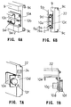
- a shield plate 8 having a vertical secondary slit 8a corresponding to the primary slit and an adjustment mechanism for the secondary slit 8a is provided at the X-ray detector 7 in face-to-face relationship with the X-ray generator 6. Behind the shield plate 8, a cassette holder 9 is disposed. As shown in FIG. 2, the cassette holder 9 is supported by a slide bearing 9a so as to be movable in the horizontal direction perpendicular to the surface of the drawing in FIG. 2. The cassette holder 9 is provided with a drive motor 9b.
- a control portion 11 comprising a PC board having a variety of circuits, and an operation panel 12 for covering the outside the control portion 11 are provided behind the slide bearing 9a of the X-ray detector 7.
- Various switches and a liquid crystal display portion (not shown) are mounted on the operation panel 12.
- a remote-control box 13 is provided, which is connected to the main body 1 of the apparatus via an operation cord 13a.
- the remote-control box 13 is provided with a main switch for power on/off operation and an X-ray irradiation switch, for example.
- the head of a patient is secured to a predetermined position on the patient frame 4b, and a film cassette 21 loaded with an X-ray film is mounted in the cassette holder 9 as shown in chain lines in FIG. 2.
- X-rays are then applied from the X-ray generator 6 to the X-ray detector 7.
- the rotary arm 5 is rotated, the center of the rotation is moved along a predetermined track.
- the cassette holder 9 accommodating the film cassette 21 is moved together with the cassette 21 in the horizontal direction at a predetermined speed. This movement is carried out by the drive motor 9b.
- FIG. 3 shows an example of the film cassette 21 replaceably loaded with an X-ray film and a sensitizing paper sheet.
- a conventional film cassette having been used generally is used here without modification as the film cassette 21.
- FIG. 4 shows an example of a digital sensor cassette 22 used for the apparatus.
- a cassette holder for the conventional film cassette can also be used without modification as the cassette holder 9.
- the upper and lower edges of the cassette holder 22 are each equipped with a cassette support piece 9c having a shape of L in cross section. Therefore, the dimensions and shape of the outer housing 23 of the digital sensor cassette 22 are made nearly identical with those of the film cassette 21.
- the dimensions and shapes of the upper edge 23a and the lower edge 23b of the outer housing 23 are selectively determined to have dimensions and shapes so as to be insertable and mountable in the space between the cassette support pieces 9c, 9c of the cassette holder 9.
- the cassette holder 9 of the X-ray detector 7 should only be configured so that the film cassette 21 and the digital sensor cassette 22 can be mounted smoothly therein, one at a time.
- the cassette holder 9 configured to be adapted for the special cassettes can also be adopted.
- the digital sensor cassette 22 is equipped with an electric X-ray image detector and various circuits related thereto inside the outer housing 23.
- a connector 24 for connection to an external circuit is provided on one side of the housing 23.
- This connector 24 is usually connected to the connector 14 of the X-ray detector 7 by a cable integrally containing power lines and signal lines.
- the connector 24 can also be connected to an external device such as a personal computer.
- the outer housing 23 is formed of an appropriate material having necessary strength, for example metal, such as an aluminum sheet, or synthetic resin, such as ABS resin.
- an X-ray receiver 25 formed of a material having high transmittance for X-rays and capable of shielding visible light, such as dark-colored ABS resin or the like, is provided in the vertical direction in correspondence with the secondary slit 8a. Inside the X-ray receiver 25, the electric X-ray image detector is disposed.
- FIG. 5 is a view showing the general structure of the electric X-ray image detector and a protection case for the detector.
- the electric X-ray image detector 26 has a three-layer structure comprising a light emitter for emitting light when irradiated with X-rays, i. e., a scintillator 26a, an optical fiber device 26b for transmitting the light emitted from the light emitter 26a, and an image pickup device portion 26c formed of a semiconductor sensor, such as CCD or MOS, having two-dimensionally disposed pixels of an image pickup device.
- This three-layer structure is integrally provided on a ceramic base 26d.
- the numeral 27 designates the protection case, and the numeral 27a designates a shield material.
- the thicknesses of the components of the electric X-ray image detector 26 are exaggerated.
- the actual thicknesses of the components are as follows: the light emitter 26a is 0.3 mm, the optical fiber device 26b is 1.5 mm, the image pickup device portion 26c is 0.5 mm, and the ceramic base 26d is 1 mm in thickness, for example.
- the pixel configuration of the image pickup device portion 26c is a two-dimensional arrangement of square pixels measuring 96 ⁇ m on each side and disposed so as to form a rectangle measuring about 6 mm in width and about 150 mm in length.
- the signals of the image pickup device portion 26c are taken out of electrodes 26e disposed on the back side of the ceramic base 26d.
- the protection case 27 is formed of a lightproof material to eliminate the influence of visible light on the electric X-ray image detector 26.
- the electric X-ray image detector 26 is covered with this protection cover 27, and is also covered with the X-ray receiver 25 on the front side thereof. In this covered condition, the electric X-ray image detector 26 is housed in the housing 23. In the case that the housing 23 is lightproof, it is possible to omit the protection case 27.
- a panoramic X-ray image can be obtained in the form of digital signals by the electric X-ray image detector 26.
- the image pickup device portion 26c comprises a semiconductor sensor, such as CCD or MOS, the digital sensor cassette 22 can have high sensitivity.
- the electric X-ray image detector 26 can smoothly receive X-rays, thereby making it possible to carry out clear radiographing.
- FIGS. 6A to 9 show examples of mechanical means
- FIGS. 10 and 11 show examples of electrical means.
- the cassette holder 9 is supported on the side of the end 5b of the rotary arm 5.
- the numeral 9a-1 designates a sliding member on the arm side, secured to the end 5b
- the numeral 9a-2 designates a sliding member on the cassette holder side, secured to the back side of the cassette holder 9.
- a rod-like tightening member 10a having a male thread 10b at its end is secured with a clamp 10c to the sliding member 9a-1 on the arm side in the longitudinal direction thereof.
- a mounting plate 10d is secured to one side of the digital sensor cassette 22 by screws, a positioning plate 10e is secured to the mounting plate 10d, and a tightening member 10f having a female thread 10g at its end is rotatably mounted on the mounting plate 10d.
- a method of mounting the digital sensor cassette 22 in the X-ray detector 7 is described below.
- the cassette 22 is mounted in the cassette holder 9 as shown in FIGS. 6B and 8A.
- the end of the positioning plate 10e is made contact with the end surface of the sliding member 9a-2 on the cassette holder side. Since the length of the cassette holder 9 is the same as that of the digital sensor cassette 22, the center of the cassette holder 9 indicated by line A is aligned with the center of the digital sensor cassette 22 provided with the X-ray receiver 25 in this condition.
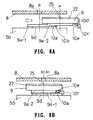
- the cassette holder 9 and the digital sensor cassette 22 are moved and inserted in the direction indicated by the arrow on the back side of the shield plate 8 so that the positioning plate 10e makes contact with the end surface of the sliding member 9a-1 as shown in FIG. 8B.
- the dimensions of the members have been selectively determined so that the X-ray receiver 25 at the center of the digital sensor cassette 22 is aligned with the center of the secondary slit 8a of the shield plate 8 indicated by line B, and so that the female thread 10g of the tightening member 10f is positioned so as to be engaged with the male thread 10b of the tightening member 10a in this contact condition.
- the digital sensor cassette 22 can be secured to a predetermined position.
- a ball-plunger arrangement shown in FIG. 9 can also be used.
- a tightening member 10h having an engagement recess 10j is secured to the mounting plate 10d.
- the tightening member 10h is provided with an engagement portion 10p wherein balls 10k projecting into the engagement recess 10j are pushed by screws 10m and springs 10n.
- the end of the tightening member 10a is provided with an engagement member 10r having an engagement groove 10q corresponding to the engagement portion 10p.
- the engagement member 10r is inserted into the engagement recess 10j, and the balls 10k of the engagement portion 10p engage the engagement groove 10q, whereby the digital sensor cassette 22 is positioned and secured at the same time.
- This securing can be released by pulling out the tightening member 10h by applying a force greater than the engagement force exerted between the engagement groove 10q and the balls 10k in correspondence with the pushing pressure of the springs 10n.
- a small slot 10s is provided at the end of the cassette holder 9.
- a reflection member 10t is provided at a position corresponding to the slot 10s on the back side of the digital sensor cassette 22, that is, at a position facing the slot 10s when the digital sensor cassette 22 is mounted in the cassette holder 9 so that the center of the digital sensor cassette 22 is aligned with the center of the cassette holder 9.
- the reflection member 10t is formed of a reflective sheet attached to the digital sensor cassette 22, for example.
- the end 5b of the rotary arm 5 is provided with a detection sensor 10u equipped with a light-emitting device and a photodetector device. The position of the detection sensor 10u is determined so as to face the reflection member 10t when the cassette holder 9 and the digital sensor cassette 22 are mounted at the predetermined position.
- the cassette holder drive motor 9b is a stepping motor. After the digital sensor cassette 22 is mounted in the cassette holder 9 and moved nearly close to the predetermined position by hand, position control is carried out in accordance with such a procedure as that shown in FIG. 11, for example. More specifically, the output of the detection sensor 10u is read, and the drive motor 9b is moved one step to the right or left in accordance with the presence or absence of reflection, and the output of the detection sensor 10u is read again. This operation is repeated, and the motor is stopped and locked at a position wherein the result of the detection of the presence or absence of reflection is reversed.
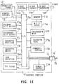
- the control portion 11 comprises a control unit 11a, such as MPU or CPU, used as a central operation control unit for the entire apparatus, input/output ports 11b and a memory 11c.
- a control unit 11a such as MPU or CPU
- an X-ray irradiation control circuit 11d an X-ray irradiation detection circuit 11e, an X-ray generation circuit 11f, a primary slit width adjustment circuit 11g, a secondary slit width adjustment circuit 11h, a cassette position detection circuit 11j, a cassette drive circuit 11k, a rotary arm rotation detection circuit 11m, a TDI clock generation circuit 11n and the like are provided, and these circuits are connected to the control unit 11a via the input/output ports 11b.
- the above-mentioned circuits have also been provided basically in a conventional apparatus used with film cassettes.
- the apparatus in accordance with the present invention further comprises a communication control circuit 11p, a cassette type detection circuit 11q, a photographing mode setting circuit 11r, a power supply circuit 11s and the like.
- These circuits, the various switches and the display portion on the operation panel 12, the various switches on the remote-control box 13 and the connector 14 are connected as shown in FIG. 12.
- the digital sensor cassette 22 is provided with a control unit 22a, such as MPU or CPU, for controlling the operations of all the circuits in the cassette 22 and the operations of the entire apparatus including the main body 1 of the apparatus, independently or integrated with the control portion 11 of the main body 1 of the apparatus.
- the digital sensor cassette 22 is further provided with input/output ports 22b, a TDI clock conversion circuit 22c, an image pickup device drive circuit 22d, an A/D converter 22e, a memory 22f, a communication control circuit 22g, a power supply circuit 22h and the like. These circuits, the electric X-ray image detector 26 and the connector 24 are connected as shown in FIG. 13.
- the digital sensor cassette 22 is mounted in the cassette holder 9.
- the cassette 22 is secured to the predetermined position by the above-mentioned means by operating the cassette position detection circuit 11j and the cassette drive circuit 11k.
- the connector 14 is connected to the connector 24 by using a cable 15 comprising wires or optical fibers and having a connector 14' on one end of the cable and a connector 24'on the other end, the connectors 14' and 24' being adapted to be connectable to the connectors 14 and 24, respectively.
- a predetermined signal circuit is formed, and communication is made possible between the digital sensor cassette 22 and the main body 1 of the panoramic radiographic apparatus, whereby various signals are transmitted therebetween.
- the radiographing mode for the digital sensor cassette 22 is selected, and various conditions in accordance with this mode are set by the photographing mode setting circuit 11r, whereby preparations for photographing are carried out.
- the type of a mounted cassette is detected by the cassette type detection circuit 11q, a photographing mode in accordance with the type of the cassette is automatically selected, and predetermined photographing conditions are set. This eliminates the need for the operator to select a photographing mode and to set photographing conditions in accordance with the type of the cassette to be used, thereby making the operation of the apparatus easy.
- the automatic selection of the photographing mode is made possible even when a film cassette having no communication function is used.
- Photographing is started by turning on the X-ray irradiation switch on the remote-control box 13.
- X-rays are applied from the X-ray generator 6 to the X-ray detector 7.
- the rotation center of the rotary arm 5 is moved and the rotary arm 5 is rotated.
- the drive motor 9b of the cassette holder 9 is stationary, and a TDI clock signal delivered at the time of photographing by using an ordinary film cassette and synchronized with the rotation of the rotary arm 5, that is, a signal for time delay integration control, is transmitted to the digital sensor cassette 22 by the rotary arm rotation detection circuit 11m and the control unit 11a.
- the image pickup device portion 26c is driven.
- the TDI clock signal is supplied in a digital or analog form, and the cassette 22 is configured to receive both types of signals.
- linear X-ray image information required for generating a panoramic X-ray image is delivered sequentially from the electric X-ray image detector 26, and transferred to the memory 22f via the A/D converter 22e.
- Generating a panoramic X-ray image is carried out sequentially beginning with its end, and the image is stored. These operations are carried out during a period between the transmission/reception of an X-ray irradiation start signal and the transmission/reception of an X-ray irradiation stop signal.
- the image process conducted at this time is an electrical process replaced with the process in accordance with the principle of obtaining panoramic X-ray images by using a method wherein a linear X-ray image is subjected to photosensing sequentially while a film cassette is moved in synchronization with the rotation of the rotary arm.
- both the film cassette and the digital sensor cassette can be used with the apparatus shown in the figures, one at a time, whereby desired panoramic X-ray images can be obtained by fully using the features of each type of cassette.
- the digital sensor cassette does not require development, whereby a panoramic X-ray image can be obtained immediately, thereby being applicable to diagnosis using computers.
- by slightly modifying an existing widespread panoramic radiographic apparatus used with a film it is possible to obtain an apparatus which can be used with the digital sensor cassette in accordance with the present invention as well as the film.
- the amount of X-ray dose in the case of the photographing mode for the digital sensor cassette can be less than that in the case of the photographing mode for the film cassette, because the sensitivity of the electric X-ray image detector 26 is higher than that of the film. Owing to this reduction in the amount of X-ray dose, the amount of X-ray exposure to the subject to be photographed can be reduced.
- the X-ray irradiation control circuit 11d is automatically controlled on the side of the main body of the panoramic radiographic apparatus depending on the type of the semiconductor sensor, such as CCD or MOS for example, used for the image pickup device 26c. and the voltage and current of the X-ray tube are set to appropriate values. However, it is possible to set the values by designating appropriate values on the side of the digital sensor cassette 22.
- the communication between the digital sensor cassette 22 and the main body 1 of the panoramic radiographic apparatus is carried out under the control of the communication control circuit 11p.
- information about the cassette such as the serial number, photographing preparation conditions and operation conditions of the cassette, are transmitted from the cassette, and some operations of the main body 1 of the apparatus are controlled in accordance with the information about the operation conditions.
- operations which cannot be conducted simultaneously are attempted by using commands during data processing or transfer on the side of the main body 1 of the apparatus, such commands are not accepted. As a result, malfunctions are prevented, and the reliability of operation is raised.
- various pieces of information about photographing such as a photographing mode, photographing preparation conditions, X-ray irradiation start/stop, X-ray tube voltage and current and an area to be photographed are included in the information transmitted from the control portion 11. These pieces of information can be used to obtain appropriate panoramic X-ray images, or used for diagnosis after photographing.
- the primary and secondary slits are adjusted in the case of narrow slit photographing, and the conditions of the adjustments are transmitted. In the case of 4-split photographing, information about the area to be photographed and the like is also transmitted.
- X-ray image information delivered from the electric X-ray image detector 26 may be stored in the memory 11c of the control portion 11 of the main body of the apparatus, instead of the memory 22f of the digital sensor cassette 22.
- the apparatus via the control portion 11 of the main body 1 of the panoramic radiographic apparatus connected to the connector 24, the apparatus can be connected to an external device 30, such as a personal computer or a large computer, or a network of these devices, and in this connection condition, a panoramic X-ray image can be indicated in real time on the display of the external device. It is also possible to connect the external device 30 to the connector 24 after photographing to directly transfer an image to the external device 30.
- the external device 30 By using a device having a high processing capability as the external device 30, it is possible to display not only panoramic X-ray images, but also data concerning photographing, such as a photographing mode, tube voltage, tube current and an area to be photographed. Moreover, it is possible to register these together with data concerning each patient, such as a patient name and ID number so as to use them for diagnosis after photographing. In this way, a variety of uses are made possible.
- FIG. 14 is a view showing an example wherein a secondary battery 31 is mounted additionally in the configuration shown in FIG. 13.
- an external battery 32 may be connected to a battery connection portion 32a disposed at an appropriate position in the housing 23 via required lead wires, or directly connected to the battery connection portion 32a by using a removable connector capable of mechanical clamping.
- a non-contact wireless communication means such as a means using infrared rays or radio waves, should only be added to the configurations shown in FIGS. 12 and 13, and the connector 24 can be omitted. Even when the secondary battery 31 is not mounted in the digital sensor cassette 22, it is needless to say that a wireless type can be used as a communication means.
- FIG. 15 shows an example of an infrared communication means.
- the control portion 11 of the main body of the panoramic radiographic apparatus is provided with an infrared control circuit 33a and its transmission/reception portion 33b.
- the digital sensor cassette 22 is provided with an infrared control circuit 34a and its transmission/reception portion 34b.
- As the transmission/reception portions 33b and 34b a light-emitting diode and a photo transistor are used.
- the light-emitting diode and the photo transistor are disposed so as to face each other when the digital sensor cassette 22 is mounted in the cassette holder 9. In particular, when the light-emitting diode and the photo transistor are disposed to face very close to each other, the output can be made smaller, and the performance can be less affected by interference.
- FIG. 16 shows an example of a radio wave communication means.
- the control portion 11 of the main body of the apparatus is provided with a radio wave control circuit 35a and its transmission/reception portion 35b.
- the digital sensor cassette 22 is provided with a radio wave control circuit 36a and its transmission/reception portion 36b.
- the frequency of a radio wave and the type of modulation may be those adopted appropriately. Therefore, the locations of the transmission/reception portions 35b and 36b can be selectively determined more freely than those in the case of the infrared type.
- FIGS. 17 and 18 show an example of a charger 41 used to charge the secondary battery 31 while the battery is kept mounted in the digital sensor cassette 22.
- a mounting portion 41b for accommodating the digital sensor cassette 22 is formed in a housing 41a, and the output portion 41d of a built-in charging circuit 41c is provided in the mounting portion 41b.
- the charge input portion 31a of the secondary battery 31 is provided on one end of the cassette 22.
- the output portion 41d can be connected to the charge input portion 31a so as to charge the secondary battery 31.
- the numeral 41e designates a power cord connected to commercial electric power.
- the charger 41 is provided with a communication circuit in correspondence with the communication type of the digital sensor cassette 22.
- the charger 41 is provided with an infrared control circuit 41f and its transmission/reception portion 41g in correspondence with the transmission/reception portion 34b.
- the transmission/reception portion 41g is disposed at the mounting portion 41b, for example.
- the transmission/reception portion 34b of the cassette 22 is disposed at a position facing the transmission/reception portion 41g when the cassette 22 is mounted in the mounting portion 41b.
- the numeral 41h designates a connection cord for connection to the external device.
- the communication means of the charger 41 should only be a type compatible with the communication means.
- the charger 41 may be provided with all types of communication means so that it can be compatible with a variety of cassettes.
- the second battery 31 as a power supply as described above, no power supply circuit is required for the main body of the panoramic radiographic apparatus. Therefore, the apparatus used with film cassettes can easily be modified so that the apparatus can be used with digital sensor cassettes. In addition, the trouble of preparing and connecting a power cable is unnecessary.
- the secondary battery 31 can be charged by mounting the cassette 22 in the charger 41, and communication to the external device can be carried out via the charger 41 during charging. Therefore, data can be transferred to the external device by effectively using the time for charging. For these reasons, data processing for reproduction of images, diagnosis after photographing and the like can be rationalized.
Landscapes
- Health & Medical Sciences (AREA)
- Life Sciences & Earth Sciences (AREA)
- Medical Informatics (AREA)
- Engineering & Computer Science (AREA)
- Physics & Mathematics (AREA)
- Heart & Thoracic Surgery (AREA)
- Surgery (AREA)
- Nuclear Medicine, Radiotherapy & Molecular Imaging (AREA)
- Optics & Photonics (AREA)
- Pathology (AREA)
- Radiology & Medical Imaging (AREA)
- Biomedical Technology (AREA)
- Biophysics (AREA)
- Molecular Biology (AREA)
- High Energy & Nuclear Physics (AREA)
- Animal Behavior & Ethology (AREA)
- General Health & Medical Sciences (AREA)
- Public Health (AREA)
- Veterinary Medicine (AREA)
- Mathematical Physics (AREA)
- Dentistry (AREA)
- Oral & Maxillofacial Surgery (AREA)
- Apparatus For Radiation Diagnosis (AREA)
- Radiography Using Non-Light Waves (AREA)
Applications Claiming Priority (6)
| Application Number | Priority Date | Filing Date | Title |
|---|---|---|---|
| JP284451/97 | 1997-09-30 | ||
| JP28445297A JP3650515B2 (ja) | 1997-09-30 | 1997-09-30 | パノラマx線撮影装置用デジタルセンサカセット |
| JP28445297 | 1997-09-30 | ||
| JP28445197A JP3639702B2 (ja) | 1997-09-30 | 1997-09-30 | パノラマx線撮影装置 |
| JP28445197 | 1997-09-30 | ||
| JP284452/97 | 1997-09-30 |
Publications (2)
| Publication Number | Publication Date |
|---|---|
| EP0904734A2 true EP0904734A2 (fr) | 1999-03-31 |
| EP0904734A3 EP0904734A3 (fr) | 2000-03-29 |
Family
ID=26555474
Family Applications (1)
| Application Number | Title | Priority Date | Filing Date |
|---|---|---|---|
| EP98117557A Withdrawn EP0904734A3 (fr) | 1997-09-30 | 1998-09-16 | Appareil radiographique panoramique et cassette avec capteur numérique pour le dit appareil |
Country Status (2)
| Country | Link |
|---|---|
| US (2) | US6173035B1 (fr) |
| EP (1) | EP0904734A3 (fr) |
Cited By (6)
| Publication number | Priority date | Publication date | Assignee | Title |
|---|---|---|---|---|
| EP1062913A1 (fr) * | 1999-06-25 | 2000-12-27 | DDI Direct Digital Imaging GmbH | Système d'imagerie par radiographie et par balayage digital |
| WO2003043317A1 (fr) * | 2001-11-15 | 2003-05-22 | Hamamatsu Photonics K.K. | Detecteur d'images et systeme d'imagerie contenant ledit detecteur |
| US7086859B2 (en) | 2003-06-10 | 2006-08-08 | Gendex Corporation | Compact digital intraoral camera system |
| WO2006105868A1 (fr) * | 2005-04-05 | 2006-10-12 | Dürr Dental GmbH & Co. KG | Ensemble de reception de panorama pour un appareil radiographique en panorama |
| DE10108385B4 (de) * | 2000-02-21 | 2013-12-19 | J. Morita Mfg. Corp. | Röntgenbilddetektor und Röntgenaufnahmevorrichtung |
| EP2818114A4 (fr) * | 2012-02-21 | 2015-11-11 | Yoshida Seisakusho Kk | Appareil d'imagerie par rayons x |
Families Citing this family (16)
| Publication number | Priority date | Publication date | Assignee | Title |
|---|---|---|---|---|
| FR2753811B1 (fr) * | 1996-09-24 | 1998-11-06 | Dispositif amovible de prise d'images numeriques destine a la radiologie | |
| FI104944B (fi) * | 1998-06-26 | 2000-05-15 | Planmeca Oy | Menetelmät, laitteet ja kuvausmoodi tomografiakuvantamisessa |
| FI104943B (fi) * | 1998-06-26 | 2000-05-15 | Planmeca Oy | Menetelmä, laite ja niiden käyttö tomografiakuvantamisessa 2 |
| EP1219147B1 (fr) | 1999-10-08 | 2006-11-08 | Gendex Corporation | Commande automatique de l'exposition pour un appareil de radiographie dentaire panoramique et de cephalographie |
| US6404854B1 (en) * | 2000-06-26 | 2002-06-11 | Afp Imaging Corporation | Dental x-ray imaging system |
| JP3964271B2 (ja) * | 2001-06-22 | 2007-08-22 | 株式会社モリタ製作所 | 医療用走査型デジタルx線撮影装置 |
| EP1551302B1 (fr) * | 2002-07-25 | 2012-02-08 | Gendex Corporation | Appareil et proc d d'imagerie radiologique num rique en temps r el |
| US7469032B2 (en) * | 2005-04-11 | 2008-12-23 | Gendex Corporation | Structural and patient positioning features of an x-ray system |
| US20060227939A1 (en) * | 2005-04-11 | 2006-10-12 | Gendex Corporation | Bite piece for a dental x-ray system |
| JP4488948B2 (ja) * | 2005-04-11 | 2010-06-23 | 株式会社モリタ製作所 | X線ct撮影用ユニットおよびx線撮影装置 |
| JP4516626B1 (ja) * | 2009-09-28 | 2010-08-04 | 株式会社吉田製作所 | 歯科用x線撮影装置 |
| US8251583B2 (en) * | 2009-12-15 | 2012-08-28 | Midmark Corporation | Removable radiation sensor for dental imaging systems |
| US20140098941A1 (en) * | 2012-10-09 | 2014-04-10 | General Electric Company | Systems for transporting x-ray detector and detector control device |
| KR20150088679A (ko) * | 2014-01-24 | 2015-08-03 | 주식회사바텍 | Ct 촬영 장치 |
| CN104887262B (zh) * | 2015-06-29 | 2017-10-20 | 青岛大学附属医院 | 数字化牙片机 |
| CN111612020B (zh) * | 2019-02-22 | 2024-04-26 | 杭州海康威视数字技术股份有限公司 | 一种异常被检物的定位方法以及安检分析设备、系统 |
Citations (6)
| Publication number | Priority date | Publication date | Assignee | Title |
|---|---|---|---|---|
| EP0209930A1 (fr) * | 1985-06-21 | 1987-01-28 | B.V. Optische Industrie "De Oude Delft" | Appareil de radiographie à fente utilisant des rayonnements à énergies différentes |
| US4773087A (en) * | 1986-04-14 | 1988-09-20 | University Of Rochester | Quality of shadowgraphic x-ray images |
| EP0554800A1 (fr) * | 1992-01-31 | 1993-08-11 | Shimadzu Corporation | Appareil à rayons X |
| JPH09135829A (ja) * | 1995-11-16 | 1997-05-27 | Morita Mfg Co Ltd | 医療用x線断層撮影装置 |
| EP0775467A1 (fr) * | 1995-11-23 | 1997-05-28 | Planmed Oy | Méthode et système pour commander les fonctions d'un appareil de mammographie |
| EP0776149A1 (fr) * | 1995-11-21 | 1997-05-28 | Loral Fairchild Corporation | Dispositif et procédé pour détecter d'images radiographiques |
Family Cites Families (6)
| Publication number | Priority date | Publication date | Assignee | Title |
|---|---|---|---|---|
| US5018177A (en) * | 1989-06-01 | 1991-05-21 | Board Of Regents, The University Of Texas System | Apparatus and method for producing digital panoramic x-ray images |
| FR2720259B1 (fr) | 1994-05-31 | 1997-11-28 | Trophy Radiologie | Appareil de radiodiagnostic du type à capteur à transfert de charge. |
| US5844961A (en) * | 1995-07-26 | 1998-12-01 | Medfx Systems | Filmless digital x-ray system |
| JP3441578B2 (ja) * | 1995-11-22 | 2003-09-02 | 株式会社モリタ製作所 | 歯科用パノラマx線撮影装置 |
| US5877501A (en) * | 1996-11-26 | 1999-03-02 | Picker International, Inc. | Digital panel for x-ray image acquisition |
| US5912942A (en) * | 1997-06-06 | 1999-06-15 | Schick Technologies, Inc. | X-ray detection system using active pixel sensors |
-
1998
- 1998-09-16 EP EP98117557A patent/EP0904734A3/fr not_active Withdrawn
- 1998-09-18 US US09/154,674 patent/US6173035B1/en not_active Expired - Fee Related
-
2000
- 2000-04-11 US US09/547,377 patent/US6219401B1/en not_active Expired - Fee Related
Patent Citations (6)
| Publication number | Priority date | Publication date | Assignee | Title |
|---|---|---|---|---|
| EP0209930A1 (fr) * | 1985-06-21 | 1987-01-28 | B.V. Optische Industrie "De Oude Delft" | Appareil de radiographie à fente utilisant des rayonnements à énergies différentes |
| US4773087A (en) * | 1986-04-14 | 1988-09-20 | University Of Rochester | Quality of shadowgraphic x-ray images |
| EP0554800A1 (fr) * | 1992-01-31 | 1993-08-11 | Shimadzu Corporation | Appareil à rayons X |
| JPH09135829A (ja) * | 1995-11-16 | 1997-05-27 | Morita Mfg Co Ltd | 医療用x線断層撮影装置 |
| EP0776149A1 (fr) * | 1995-11-21 | 1997-05-28 | Loral Fairchild Corporation | Dispositif et procédé pour détecter d'images radiographiques |
| EP0775467A1 (fr) * | 1995-11-23 | 1997-05-28 | Planmed Oy | Méthode et système pour commander les fonctions d'un appareil de mammographie |
Non-Patent Citations (1)
| Title |
|---|
| PATENT ABSTRACTS OF JAPAN vol. 1997, no. 09, 30 September 1997 (1997-09-30) & JP 09 135829 A (MORITA MFG CO LTD), 27 May 1997 (1997-05-27) * |
Cited By (10)
| Publication number | Priority date | Publication date | Assignee | Title |
|---|---|---|---|---|
| EP1062913A1 (fr) * | 1999-06-25 | 2000-12-27 | DDI Direct Digital Imaging GmbH | Système d'imagerie par radiographie et par balayage digital |
| WO2001000092A1 (fr) | 1999-06-25 | 2001-01-04 | Ddi Direct Digital Imaging Gmbh | Appareil de balayage numerique aux rayons x |
| DE10108385B4 (de) * | 2000-02-21 | 2013-12-19 | J. Morita Mfg. Corp. | Röntgenbilddetektor und Röntgenaufnahmevorrichtung |
| WO2003043317A1 (fr) * | 2001-11-15 | 2003-05-22 | Hamamatsu Photonics K.K. | Detecteur d'images et systeme d'imagerie contenant ledit detecteur |
| US7091465B2 (en) | 2001-11-15 | 2006-08-15 | Hamamatsu Photonics K.K. | Image sensor with a voltage maintaining capacitor and an ac-signal blocking resistor, and imaging system comprising the image sensor |
| US7086859B2 (en) | 2003-06-10 | 2006-08-08 | Gendex Corporation | Compact digital intraoral camera system |
| WO2006105868A1 (fr) * | 2005-04-05 | 2006-10-12 | Dürr Dental GmbH & Co. KG | Ensemble de reception de panorama pour un appareil radiographique en panorama |
| US8102965B2 (en) | 2005-04-05 | 2012-01-24 | Michael Thoms | Panoramic recording device for a panoramic X-ray machine |
| EP2818114A4 (fr) * | 2012-02-21 | 2015-11-11 | Yoshida Seisakusho Kk | Appareil d'imagerie par rayons x |
| US9510795B2 (en) | 2012-02-21 | 2016-12-06 | The Yoshida Dental Mfg. Co., Ltd. | Radiographic X-ray equipment |
Also Published As
| Publication number | Publication date |
|---|---|
| US6173035B1 (en) | 2001-01-09 |
| US6219401B1 (en) | 2001-04-17 |
| EP0904734A3 (fr) | 2000-03-29 |
Similar Documents
| Publication | Publication Date | Title |
|---|---|---|
| EP0904734A2 (fr) | Appareil radiographique panoramique et cassette avec capteur numérique pour le dit appareil | |
| US9072485B2 (en) | Radiation imaging apparatus | |
| US7015478B2 (en) | X-ray imaging apparatus | |
| EP1263322B1 (fr) | Camera numerique, imageur et procede d'imagerie numerique | |
| CN104939851A (zh) | 电子暗盒 | |
| JP2000347330A (ja) | カセッテ型放射線画像読取装置 | |
| JP2002052015A (ja) | 平面型放射線検出器ユニット及びx線撮像装置 | |
| US7740405B2 (en) | Cassette | |
| US8727617B2 (en) | Dental X-ray device and X-ray sensor | |
| US5729587A (en) | X-ray exposure apparatus | |
| JP3650515B2 (ja) | パノラマx線撮影装置用デジタルセンサカセット | |
| JP3639702B2 (ja) | パノラマx線撮影装置 | |
| JP2014045939A (ja) | 放射線撮影システムおよびその通信方法、並びに放射線画像検出装置 | |
| JP3964152B2 (ja) | X線センサカセット及びx線撮影装置 | |
| JP2000175906A (ja) | パノラマx線撮影装置 | |
| JP3611084B2 (ja) | 放射線検出用カセッテ撮像システム及びそれに使用されるカセッテスタンド | |
| JP2013205386A (ja) | 放射線画像撮影装置 | |
| JP2013096761A (ja) | 放射線画像撮影装置 | |
| US20010021243A1 (en) | Radiography apparatus | |
| KR101993179B1 (ko) | 구강내 센서 | |
| JP2003079617A (ja) | X線センサーユニット、これを用いたx線撮像装置 | |
| JP2010012060A (ja) | 可搬型放射線画像検出器および放射線画像撮影システム | |
| JP2013096762A (ja) | 放射線画像撮影装置、放射線画像撮影システム及び放射線画像撮影装置の撮影制御方法 | |
| JP2013097074A (ja) | 放射線画像撮影装置 | |
| JP4561730B2 (ja) | カセッテ型放射線画像読取装置 |
Legal Events
| Date | Code | Title | Description |
|---|---|---|---|
| PUAI | Public reference made under article 153(3) epc to a published international application that has entered the european phase |
Free format text: ORIGINAL CODE: 0009012 |
|
| AK | Designated contracting states |
Kind code of ref document: A2 Designated state(s): DE FI FR |
|
| AX | Request for extension of the european patent |
Free format text: AL;LT;LV;MK;RO;SI |
|
| PUAL | Search report despatched |
Free format text: ORIGINAL CODE: 0009013 |
|
| AK | Designated contracting states |
Kind code of ref document: A3 Designated state(s): AT BE CH CY DE DK ES FI FR GB GR IE IT LI LU MC NL PT SE |
|
| AX | Request for extension of the european patent |
Free format text: AL;LT;LV;MK;RO;SI |
|
| 17P | Request for examination filed |
Effective date: 20000707 |
|
| AKX | Designation fees paid |
Free format text: DE FI FR |
|
| 17Q | First examination report despatched |
Effective date: 20041022 |
|
| GRAP | Despatch of communication of intention to grant a patent |
Free format text: ORIGINAL CODE: EPIDOSNIGR1 |
|
| STAA | Information on the status of an ep patent application or granted ep patent |
Free format text: STATUS: THE APPLICATION IS DEEMED TO BE WITHDRAWN |
|
| 18D | Application deemed to be withdrawn |
Effective date: 20091222 |