EP0401647B1 - Locking mechanism - Google Patents
Locking mechanism Download PDFInfo
- Publication number
- EP0401647B1 EP0401647B1 EP90110184A EP90110184A EP0401647B1 EP 0401647 B1 EP0401647 B1 EP 0401647B1 EP 90110184 A EP90110184 A EP 90110184A EP 90110184 A EP90110184 A EP 90110184A EP 0401647 B1 EP0401647 B1 EP 0401647B1
- Authority
- EP
- European Patent Office
- Prior art keywords
- key
- code
- locking device
- lock
- lock cylinder
- Prior art date
- Legal status (The legal status is an assumption and is not a legal conclusion. Google has not performed a legal analysis and makes no representation as to the accuracy of the status listed.)
- Expired - Lifetime
Links
Images

Classifications
-
- G—PHYSICS
- G07—CHECKING-DEVICES
- G07C—TIME OR ATTENDANCE REGISTERS; REGISTERING OR INDICATING THE WORKING OF MACHINES; GENERATING RANDOM NUMBERS; VOTING OR LOTTERY APPARATUS; ARRANGEMENTS, SYSTEMS OR APPARATUS FOR CHECKING NOT PROVIDED FOR ELSEWHERE
- G07C9/00—Individual registration on entry or exit
- G07C9/00174—Electronically operated locks; Circuits therefor; Nonmechanical keys therefor, e.g. passive or active electrical keys or other data carriers without mechanical keys
- G07C9/00182—Electronically operated locks; Circuits therefor; Nonmechanical keys therefor, e.g. passive or active electrical keys or other data carriers without mechanical keys operated with unidirectional data transmission between data carrier and locks
-
- E—FIXED CONSTRUCTIONS
- E05—LOCKS; KEYS; WINDOW OR DOOR FITTINGS; SAFES
- E05B—LOCKS; ACCESSORIES THEREFOR; HANDCUFFS
- E05B47/00—Operating or controlling locks or other fastening devices by electric or magnetic means
- E05B47/06—Controlling mechanically-operated bolts by electro-magnetically-operated detents
- E05B47/0611—Cylinder locks with electromagnetic control
- E05B47/0619—Cylinder locks with electromagnetic control by blocking the rotor
- E05B47/0623—Cylinder locks with electromagnetic control by blocking the rotor axially, i.e. with an axially engaging blocking element
-
- E—FIXED CONSTRUCTIONS
- E05—LOCKS; KEYS; WINDOW OR DOOR FITTINGS; SAFES
- E05B—LOCKS; ACCESSORIES THEREFOR; HANDCUFFS
- E05B47/00—Operating or controlling locks or other fastening devices by electric or magnetic means
- E05B47/0001—Operating or controlling locks or other fastening devices by electric or magnetic means with electric actuators; Constructional features thereof
- E05B47/0002—Operating or controlling locks or other fastening devices by electric or magnetic means with electric actuators; Constructional features thereof with electromagnets
- E05B47/0006—Operating or controlling locks or other fastening devices by electric or magnetic means with electric actuators; Constructional features thereof with electromagnets having a non-movable core; with permanent magnet
-
- E—FIXED CONSTRUCTIONS
- E05—LOCKS; KEYS; WINDOW OR DOOR FITTINGS; SAFES
- E05B—LOCKS; ACCESSORIES THEREFOR; HANDCUFFS
- E05B49/00—Electric permutation locks; Circuits therefor ; Mechanical aspects of electronic locks; Mechanical keys therefor
-
- G—PHYSICS
- G07—CHECKING-DEVICES
- G07C—TIME OR ATTENDANCE REGISTERS; REGISTERING OR INDICATING THE WORKING OF MACHINES; GENERATING RANDOM NUMBERS; VOTING OR LOTTERY APPARATUS; ARRANGEMENTS, SYSTEMS OR APPARATUS FOR CHECKING NOT PROVIDED FOR ELSEWHERE
- G07C9/00—Individual registration on entry or exit
- G07C9/00174—Electronically operated locks; Circuits therefor; Nonmechanical keys therefor, e.g. passive or active electrical keys or other data carriers without mechanical keys
- G07C2009/00753—Electronically operated locks; Circuits therefor; Nonmechanical keys therefor, e.g. passive or active electrical keys or other data carriers without mechanical keys operated by active electrical keys
- G07C2009/00761—Electronically operated locks; Circuits therefor; Nonmechanical keys therefor, e.g. passive or active electrical keys or other data carriers without mechanical keys operated by active electrical keys with data transmission performed by connected means, e.g. mechanical contacts, plugs, connectors
Definitions
- the invention relates to a locking device according to the preamble of claim 1.
- Locking systems in larger objects such as blocks of flats, schools, administrative buildings or industrial companies are usually arranged in a security hierarchy, so that only individual locks can be opened with certain keys, while keys of a higher hierarchical level fit into other locks and a general key of the highest hierarchical level opens all of them Locks enabled.
- keys of a higher hierarchical level fit into other locks and a general key of the highest hierarchical level opens all of them Locks enabled.
- people who use these objects receive the key assigned to the relevant hierarchy level.
- access control systems with card systems that work electronically are also known.
- the authorized person pushes the card into a slot, which is then read and evaluated electronically and automatically opens the relevant door when the authorization is determined.
- Such access control systems are very complex to install, but they have the advantage that the authorization of these cards can be deleted if individual cards are lost, so that the system can otherwise be operated without compromising security.
- Locking devices which represent a combination of mechanical and electronic coding, offer an increase in security compared to locking systems working with purely mechanical coding, with reduced investment costs compared to access control systems with cards.
- Such locking devices are described, for example, in a brochure by Bauer Kabaabotechnik GmbH Co. & KG.
- the invention has for its object to improve a locking device according to the preamble of claim 1 so that the locking device is faster, easier and more economical to perform when installing or upgrading existing locking systems.
- An important aspect of the invention is that the energy source is not arranged in the lock unit, but in the key. If the energy source of a key is then exhausted, there is still the possibility of opening the lock with another key, so it has not become completely unusable.
- the cumbersome exchange of an independent energy source otherwise located in the lock unit or the laying of corresponding power supply lines to the lock unit is eliminated.
- the need for space is reduced by eliminating such an energy source, so that it is possible to arrange the code evaluator with the unlocking device in the locking cylinder.
- the unlocking device comprises an electromagnetically actuated, mechanical flip-flop.
- a practical embodiment of the mechanical flip-flop comprises a magnet armature designed as a latch which, when tightened by an electromagnet, releases a bolt which can be displaced against the force of a spring.
- the latch is only briefly tightened in this embodiment and the bolt, which is biased against the spring force, can then retreat and release the rotary movement of the lock cylinder insert. Once tightened, the latch can then fall off the pole pieces and return to its starting position after the opening process and removal of the key, as soon as the bolt has returned to its end position due to the spring force.
- the spring rests stationary at one end, is supported against the bolt in the central region and carries a stop surface for the key shaft at the free end, which, when the key is inserted, has a Unlocking force exerts on the bolt.
- the same spring is thus biased by the biasing force of the key so that the bolt experiences a force in the opening direction and can relax when the key is removed, whereby the bolt receives a force in the closing direction.
- the trap is arranged under the vertically mounted electromagnet and is pivotally mounted about a horizontal axis.
- the trap can move back to its starting position without additional spring force, namely exclusively under the influence of gravity, and snap in behind the bolt.
- the unlocking device comprises an electromagnet, which via a capacitor arranged in the locking cylinder and chargeable by the energy source located in the key, if the code of Key and lock cylinder can be energized.
- the energy supply lines are designed for one polarity through the key shaft with the locking cylinder and for the other polarity through a contact at the end of the key shaft with a central contact of the locking cylinder, preferably the stop surface on the spring.
- the contact in the locking cylinder is very well protected against damage and dirt.
- the spring pressure ensures reliable contact and mechanical cleaning of the contacts. Contact resistances that otherwise occur at low operating voltages Function could be impaired in this way.
- the arrangement of the contact on the key also ensures a high short-circuit protection when carrying the key together with other keys, since practically no contact with them can take place at the end of the key.
- the contacts at the root of the key shaft on the one hand and in the locking cylinder are formed by corresponding contacts which are in alignment with the contacts on the key when the key is in the inserted state.
- An additional measure to improve short-circuit safety is that the key carries a sliding contact cover when inserted into the lock cylinder.
- This contact cover normally lies over the contacts, so that when the relevant key is carried on the key ring, contact with other keys can also not lead to bridging of the corresponding contacts for the power supply lines. Furthermore, it is also possible to provide the key with a manually operated button that is looped into the power supply lines.
- a particularly advantageous embodiment for improving the short-circuit protection and protecting the battery from undesired discharges is a solution which comprises a timer circuit in the key which only briefly releases a charging current for the charging capacitor.
- a development of this embodiment provides that the timer circuit via a The feedback line can be connected to the code evaluator in the key and can only be initialized if the code matches.
- the current required to actuate the unlocking device is only taken from the key-side energy source if the key is in the lock cylinder and the authorization to open the lock has been proven.
- a practical embodiment of the code transmitter comprises a code memory, a controller circuit for code word formation and a data transmitter
- a practical embodiment of the code evaluator comprises a data receiver, a code memory and a controller circuit for code word comparison, which is connected to a control input of the unlocking device.
- the keys and the locking cylinders of the locking device contain partially identical components, which enable cost-effective production in mass production, and differ only in the memory contents of the code memories.
- the Change authorizations because, for example, they specify different hierarchy levels for keys or delete the codes of individual keys for locking cylinders or record those of other keys.
- the code evaluator additionally comprises a data transmitter arranged in a feedback line, controlled by its controller circuit, and the code transmitter comprises a data receiver connected to its controller circuit.
- a code match signal can be transmitted to the code-side controller circuit, which serves to initialize the timer circuit.
- the authorization check takes place until the lock cylinder is released in dialog, which provides additional security against misuse and, at the same time, the key-side energy source is only used if there is authorization to open the lock.
- the energy supply lines are also provided for data transmission.
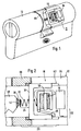
- a lock cylinder 12 is shown, which does not differ in its external design and in its dimensions from conventional mechanical lock cylinders. It can therefore be replaced with the original lock cylinder in a conventional mechanical lock.
- While vertical locking pins can be arranged in the area on the left in the drawing, which enable conventional mechanical coding, is located in the rear part of a code evaluator 16 with an unlocking device 18.
- This unlocking device serves to lock the rotary insert 66 of the locking cylinder 12.
- the unlocking device 18 is shown in detail in FIG. 2. It comprises a mechanical flip-flop 26, which consists of a displaceable latch 34, a spring 32, an electromagnet 30 and a latch 28.
- the bolt 34 is located in a longitudinal groove 62, which is located both in the housing 64 of the locking cylinder and in the rotatable part 66 and overlaps both parts in the locked state, so that a positive connection between the housing 64 of the locking cylinder 12 and the rotatable part 66 consists.
- the spring 32 is stationary at one end on the electromagnet 30 and is supported in the central region against the bolt 34. At the free end, the spring 32 carries a stop surface 36, against which the key shaft of the key 10, which is partially shown here, presses in the inserted state. In this way, the key shaft 38 exerts an unlocking force on the bolt 34. If the key 10 is removed, the Latch 34 is pressed by the spring 32 to the left against its stop and brings about the aforementioned locking between the rotatable part 66 and the housing 64 of the locking cylinder 12.
- the spring 32 When the key 10 is inserted, the spring 32 is compressed by the contact of the key shaft 38 with the stop surface 36 to such an extent that a force is exerted in the opposite direction, ie to the right.
- the displacement of the bolt 34 is blocked by the latch 28, which is arranged here vertically under the electromagnet 30 and is pivotally mounted about a horizontal axis. The trap 28 thus falls back into the starting position under the force of gravity.
- the latch 28 since it is designed as a magnet armature, is briefly attracted to the electromagnet 30 and indicates the displacement path for the bolt 34 free. After the trap 28 drops when the current pulse in the electromagnet 30 subsides, the trap 28 lies on one Leg of the bolt 34. The bolt 34 is now in the right end position and only engages in the area of the longitudinal grooves 62 located in the housing 64 of the locking cylinder 12. Thus, the positive connection between the housing 64 and the rotatable part 66 is released and the lock can be opened by turning the rotatable part by means of the key 10.
- FIG. 2 also shows the energy supply lines 22 and 24, via which electrical energy for actuating the electromagnet 30 is conducted from the energy source arranged in the key to the code evaluator 16 and the unlocking device 18.
- One power supply line 22 is formed by the key shaft and the housing 64 of the locking cylinder 12 and the other by a central contact 42 at the end of the key shaft 38 and the stop surface 36 and the spring 32. From there, conventional wiring lines lead to the code evaluator 16 and to the electromagnet 30 .
- the power supply lines 22 and 24 also serve for data transmission at the same time.
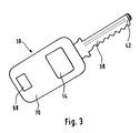
- Fig. 3 shows a plan view of a key 10 of the locking device according to the invention.
- the key 10 has a conventional key handle 70 in which a code transmitter 14 and an energy source 20 are arranged. At 68 there is also a type plate for identification of the key number.
- the key shaft 38 is located on the handle 70, which is designed here as a key bit with the usual mechanical coding. At the front end of the key shaft 38, the contact 42 can be seen, which forms one part of the energy supply lines 22, 24, while the other part is represented by the remaining key shaft 38.
- the key 10 can be used in addition to the use in locking devices of the type according to the invention in conventional locks which work as part of a locking system exclusively with mechanical coding.
- locking devices with electronic locking components also in the locking cylinder the security against misuse is increased by the additional mechanical coding.
- FIG. 4 shows a circuit diagram of the lock cylinder 12 arranged code evaluator 16. This comprises a data receiver 52, a code memory 54 and a controller circuit 56 for code word comparison. In addition, a charging capacitor 40 is provided, which supplies the energy for the unlocking device 18.
- the code memory 54 can contain the codes of one or more key numbers. If there is a match, a control signal is emitted on the one hand to the unlocking device 18, of which a switching transistor 72 and the magnet coil of the electromagnet 30 are shown here. In addition, a code match signal is transmitted back to the code transmitter 14 via a data transmitter 58.
- the charging capacitor 40 is then charged via a diode 74 and the stored charge is transferred as a current pulse to the magnetic coil of the electromagnet 30 after the switching transistor 32 has been released. This is followed by the brief tightening of the latch 28 mentioned in connection with the description of FIG. 2, so that the bolt 34 is released.
- the diode 74 in connection with the charging capacitor 40 also serves to screen the supply voltage of the electronic assemblies so that their function is not impaired by the energization of the solenoid of the electromagnet 30.
- the code transmitter 14 comprises a code memory 46, a controller circuit 48 for code word formation and a data transmitter 50.
- the energy source 20, a data receiver 60 and a timer circuit 44 are also provided.
- One or more code numbers can be contained in the code memory 46 of the code transmitter 14 if the key is, for example, the authorization for several locks of a lower one Hierarchical level.
- the stored code is transmitted from the controller circuit 48 via the data transmitter 50 to the code evaluator 16 of the locking cylinder 12. The transmission takes place here via the energy supply lines 22 and 24, the contact 42 at the end of the key shaft 38 being shown as the output.
- the energy supply of the code transmitter 14 takes place from the energy source 20 formed by a battery via resistors 76 and 78.
- the resistor 76 also forms a series resistor for the energy supply of the code evaluator 16.
- a code matching signal supplied by the code evaluator 16 passes through the data receiver 60 to the controller circuit 48 and causes the controller circuit 48 to initialize the timer circuit 44. This then switches through the switching transistor 80 for a limited time and thereby bridges the series resistor 76, so that the full charging current can flow from the energy source 20 into the charging capacitor 40. After completion of the charging process, the timer circuit 44 blocks the switching transistor 80 again.
- charging of the charging capacitor 40 does not always take place every time the key 10 comes into contact with a locking cylinder 12, rather charging is limited to the cases in which a code match has been found and energy is actually required to energize the electromagnet 30.
- the charging capacitor 40 will also charge partially via the resistors 76 and 78 even before the switching transistor 80 is switched on. If it should be shown that this amount of charge should already be sufficient to actuate the electromagnet 30, switching of the switching transistor 80 would be unnecessary, as a result of which the key's energy source could be relieved.
- the invention can also be implemented without such a charging capacitor if the energy source 20 provided in the key is dimensioned sufficiently strong. In the first working phase, when checking for code conformity, there is only a minimal load on the energy source 20 because of the very low current that the electronic circuits require.
- code memories 46, 54 can of course be reprogrammed in a manner known per se with a programming device in order to change the authorizations of a key in the desired manner.
Landscapes
- Physics & Mathematics (AREA)
- Engineering & Computer Science (AREA)
- Computer Networks & Wireless Communication (AREA)
- General Physics & Mathematics (AREA)
- Electromagnetism (AREA)
- Lock And Its Accessories (AREA)
- Investigating Or Analysing Biological Materials (AREA)
- Centrifugal Separators (AREA)
- Non-Silver Salt Photosensitive Materials And Non-Silver Salt Photography (AREA)
Abstract
Description
Die Erfindung betrifft eine Schließvorrichtung nach dem Oberbegriff des Anspruchs 1.The invention relates to a locking device according to the preamble of claim 1.
Schließanlagen in größeren Objekten, wie Wohnblöcken, Schulen, Verwaltungsgebäuden oder Industriebetrieben sind meist in einer Sicherheitshierarchie geordnet, so daß mit bestimmten Schlüsseln nur einzelne Schlösser geöffnet werden können, während Schlüssel einer höheren Hierarchiestufe in weitere Schlösser passen und ein Generalschlüssel der höchsten Hierarchiestufe die Öffnung aller Schlösser ermöglicht. Personen, die in diesen Objekten verkehren, erhalten je nach ihrer Berechtigung, zu bestimmten Räumen Zutritt zu erhalten, den der entsprechenden Hierarchiestufe zugeordneten Schlüssel.Locking systems in larger objects, such as blocks of flats, schools, administrative buildings or industrial companies are usually arranged in a security hierarchy, so that only individual locks can be opened with certain keys, while keys of a higher hierarchical level fit into other locks and a general key of the highest hierarchical level opens all of them Locks enabled. Depending on their authorization to gain access to certain rooms, people who use these objects receive the key assigned to the relevant hierarchy level.
Geht ein Schlüssel einer höheren Hierarchiestufe verloren, so ist es aus Sicherheitsgründen erforderlich, alle Schlösser dieser Hierarchiestufe auszutauschen. Das kann z.B. bei Verlust des Generalschlüssels einen erheblichen Kostenaufwand verursachen.If a key of a higher hierarchy level is lost, it is necessary for security reasons to exchange all locks of this hierarchy level. This can e.g. if the master key is lost, it can cause considerable costs.
Für besonders sicherheitsrelevante Bereiche sind außerdem Zugangskontrollanlagen mit Kartensystemen bekannt, die elektronisch arbeiten. Die berechtigte Person schiebt die Karte in einen Schlitz, die daraufhin elektronisch gelesen und ausgewertet wird und bei Feststellung der Berechtigung die Öffnung der betreffenden Tür automatisch veranlaßt. Derartige Zugangskontrollanlagen sind in der Installation sehr aufwendig, sie haben aber den Vorteil, daß bei Verlust einzelner Karten die Berechtigung dieser Karten gelöscht werden kann, so daß die Anlage ansonsten ohne Sicherheitseinbuße weiterbetrieben werden kann.For particularly security-relevant areas, access control systems with card systems that work electronically are also known. The authorized person pushes the card into a slot, which is then read and evaluated electronically and automatically opens the relevant door when the authorization is determined. Such access control systems are very complex to install, but they have the advantage that the authorization of these cards can be deleted if individual cards are lost, so that the system can otherwise be operated without compromising security.
Eine Erhöhung der Sicherheit gegenüber mit rein mechanischer Codierung arbeitenden Schließanlagen bei verringerten Investitionskosten gegenüber den Zugangskontrollanlagen mit Karten bieten Schließvorrichtungen, welche eine Kombination von mechanischen und elektronischen Codierungen darstellen. Solche Schließvorrichtungen sind z.B. in einer Prospektdruckschrift der Firma Bauer Kaba Sicherheitstechnik GmbH Co. & KG beschrieben.Locking devices, which represent a combination of mechanical and electronic coding, offer an increase in security compared to locking systems working with purely mechanical coding, with reduced investment costs compared to access control systems with cards. Such locking devices are described, for example, in a brochure by Bauer Kaba Sicherheitstechnik GmbH Co. & KG.
Bei diesem System werden nur die Türen von besonders sicherheitsrelevanten Bereichen mit Schlössern versehen, die eine elektronische Codeauswertung durchführen, während im übrigen die billigeren mechanischen Schließzylinder mit entsprechend dann nur rein mechanisch arbeitenden Schlüsseln beibehalten werden können. Geht in diesem Fall ein Schlüssel, der für den Zugang von sicherheitsrelevanten Bereichen vorgesehen ist, verloren, so kann der diesem Schlüssel zugeordnete Code gelöscht werden, und die Schließvorrichtung im übrigen weiterbenutzt werden.In this system, only the doors of particularly security-relevant areas are provided with locks that carry out electronic code evaluation, while the cheaper mechanical locking cylinders can be retained with keys that then only work purely mechanically. If in this case a key that is intended for access to security-relevant areas is lost, the code assigned to this key can be deleted and the locking device can be used for the rest.
Bei diesem bekannten System befindet sich im Schlüssel ein Codegeber und in der aus Schloß und Schließzylinder gebildeten Schloßeinheit ein Codeauswerter mit einer Entsperrvorrichtung. Die Energiequelle befindet sich dabei jeweils in der Schloßeinheit und speist beim Einstecken des Schlüssels in das Schloß den im Schlüssel befindlichen Codegeber mit elektrischer Energie. Die Speisung kann dabei galvanisch, induktiv oder kapazitiv oder auch durch Infrarot-Strahlung erfolgen.In this known system there is a code transmitter in the key and a code evaluator with an unlocking device in the lock unit formed from the lock and lock cylinder. The energy source is located in each case in the lock unit and feeds the code transmitter located in the key with electrical energy when the key is inserted into the lock. The supply can take place galvanically, inductively or capacitively or also by infrared radiation.
Bei Türen, die mit derartigen elektronischen Schloßeinheiten versehen werden sollen, ist das vorhandene Einsteckschloß komplett durch ein elektronisches Schloß auszutauschen. Der Aufwand ist dementsprechend hoch, wenn auch geringer, als bei der Installation der bereits erwähnten Zugangskontrollanlagen mit Kartenlesern. Erfolgt die Energieversorgung der elektronischen Komponenten in der Schloßeinheit aus dem Versorgungsnetz, so sind zusätzlich elektrische Leitungen zu den Türen zu verlegen. Bei Batteriebetrieb entfällt zwar die Verlegung derartiger Leitungen, es ist dann jedoch darauf zu achten, daß die Batterien rechtzeitig ausgetauscht werden müssen, damit das Schloß nicht bei Erschöpfung der Batterie nicht mehr betätigbar ist.In the case of doors that are to be provided with such electronic lock units, the existing mortise lock must be replaced completely by an electronic lock. The effort is correspondingly high, albeit less than when installing the access control systems with card readers already mentioned. If the power supply for the electronic components in the lock unit comes from the supply network, then additional electrical cables must be laid to the doors. In the case of battery operation, there is no need to lay such lines, but it must then be ensured that the batteries must be replaced in good time so that the lock can no longer be operated when the battery is exhausted.
Der Erfindung liegt die Aufgabe zugrunde, eine Schließvorrichtung nach dem Oberbegriff des Anspruchs 1 dahingehend zu verbessern, daß die Schließvorrichtung bei Neuinstallation oder Umrüstung vorhandener Schließanlagen schneller, einfacher und wirtschaftlicher durchführbar ist.The invention has for its object to improve a locking device according to the preamble of claim 1 so that the locking device is faster, easier and more economical to perform when installing or upgrading existing locking systems.
Diese Aufgabe wird bei einer Schließvorrichtung nach dem Oberbegriff des Anspruchs 1 durch die im kennzeichnenden Teil angegebenen Merkmale gelöst.This object is achieved in a locking device according to the preamble of claim 1 Part specified features solved.
Ein wichtiger Aspekt der Erfindung liegt darin, daß die Energiequelle nicht in der Schloßeinheit, sondern im Schlüssel angeordnet wird. Wenn die Energiequelle eines Schlüssels dann erschöpft ist, besteht immer noch die Möglichkeit, das Schloß mit einem anderen Schlüssel zu öffnen, ist also nicht gänzlich unbenutzbar geworden. Außerdem entfällt der umständliche Austausch einer sonst in der Schloßeinheit befindlichen autarken Energiequelle oder die Verlegung entsprechender Energieversorgungsleitungen zur Schloßeinheit. Gleichzeitig wird auch der nötige Raumbedarf durch Wegfall einer solchen Energiequelle verringert, so daß es gelingt, den Codeauswerter mit der Entsperrvorrichtung im Schließzylinder anzuordnen. Bei Umrüstung vorhandener Schloßeinheiten braucht dann nur der Schließzylinder, nicht jedoch das gesamte Einsteckschloß ersetzt zu werden.An important aspect of the invention is that the energy source is not arranged in the lock unit, but in the key. If the energy source of a key is then exhausted, there is still the possibility of opening the lock with another key, so it has not become completely unusable. In addition, the cumbersome exchange of an independent energy source otherwise located in the lock unit or the laying of corresponding power supply lines to the lock unit is eliminated. At the same time, the need for space is reduced by eliminating such an energy source, so that it is possible to arrange the code evaluator with the unlocking device in the locking cylinder. When converting existing lock units, only the lock cylinder then needs to be replaced, but not the entire mortise lock.
Eine Weiterbildung sieht vor, daß die Entsperrvorrichtung ein elektromagnetisch betätigbares, mechanisches Flip-Flop umfaßt.A further development provides that the unlocking device comprises an electromagnetically actuated, mechanical flip-flop.
Dadurch gelingt es, die zur Betätigung der Entsperrvorrichtung notwendige elektrische Energie extrem zu verringen, so daß die Lebensdauer der in den Schlüsseln angeordneten Energiequellen besonders hoch ist.This makes it possible to operate the unlocking device to reduce the necessary electrical energy extremely, so that the life of the energy sources arranged in the keys is particularly long.
Eine praktische Ausgestaltung des mechanischen Flip-Flops umfaßt einen als Falle ausgebildeten Magnetanker, der bei Anzug durch einen Elektromagneten einen gegen die Kraft einer Feder verschiebbaren Riegel freigibt.A practical embodiment of the mechanical flip-flop comprises a magnet armature designed as a latch which, when tightened by an electromagnet, releases a bolt which can be displaced against the force of a spring.
Die Falle wird bei dieser Ausgestaltung nur kurzzeitig angezogen und der gegen die Federkraft vorgespannte Riegel kann dann zurückweichen und die Drehbewegung des Schließzylindereinsatzes freigeben. Einmal angezogen, kann die Falle dann wieder von den Polschuhen abfallen und nach Beendigung des Öffnungsvorganges und Herausziehen des Schlüssels in ihre Ausgangslage zurückkehren, sobald der Riegel wieder durch die Federkraft in seine Endstellung gelangt ist.The latch is only briefly tightened in this embodiment and the bolt, which is biased against the spring force, can then retreat and release the rotary movement of the lock cylinder insert. Once tightened, the latch can then fall off the pole pieces and return to its starting position after the opening process and removal of the key, as soon as the bolt has returned to its end position due to the spring force.
In Weiterbildung dieser Ausgestaltung ist vorgesehen, daß die Feder an einem Ende stationär anliegt, sich im mittleren Bereich gegen den Riegel abstützt und am freien Ende einer Anschlagfläche für den Schlüsselschaft trägt, die bei eingestecktem Schlüssel eine Entriegelungskraft auf den Riegel ausübt.In a further development of this embodiment it is provided that the spring rests stationary at one end, is supported against the bolt in the central region and carries a stop surface for the key shaft at the free end, which, when the key is inserted, has a Unlocking force exerts on the bolt.
Dieselbe Feder wird also durch die Vorspannkraft des Schlüssels einmal so vorgespannt, daß der Riegel eine Kraft in Öffnungsrichtung erfährt und kann sich bei Abziehen des Schlüssels wieder entspannen, wodurch der Riegel eine Kraft in Schließrichtung vermittelt erhält.The same spring is thus biased by the biasing force of the key so that the bolt experiences a force in the opening direction and can relax when the key is removed, whereby the bolt receives a force in the closing direction.
Zur weiteren Vereinfachung ist vorgesehen, daß die Falle unter dem senkrecht montierten Elektromagneten angeordnet und um eine waagerechte Achse schwenkbar gelagert ist.For further simplification, it is provided that the trap is arranged under the vertically mounted electromagnet and is pivotally mounted about a horizontal axis.
Dadurch kann sich die Falle nach Abklingen des Anzugsimpulses ohne zusätzliche Federkraft, nämlich ausschließlich unter dem Einfluß der Schwerkraft wieder in ihre Ausgangslage zurückbewegen und hinter dem Riegel einrasten.As a result, after the tightening pulse has subsided, the trap can move back to its starting position without additional spring force, namely exclusively under the influence of gravity, and snap in behind the bolt.
Bei einer praktischen Ausgestaltung der Erfindung umfaßt die Entsperrvorrichtung einen Elektromagneten, der über ein im Schließzylinder angeordneten und von der im Schlüssel befindlichen Energiequelle aufladbaren Kondensator bei Übereinstimmung des Codes von Schlüssel und Schließzylinder bestrombar ist.In a practical embodiment of the invention, the unlocking device comprises an electromagnet, which via a capacitor arranged in the locking cylinder and chargeable by the energy source located in the key, if the code of Key and lock cylinder can be energized.
Hierdurch gelingt es, selbst bei hohem Innenwiderstand der schlüsselseitigen Energiequelle den zum zuverlässigen Anzug der Falle erforderlichen, kurzzeitigen Energieimpuls zu liefern. Dadurch lassen sich im Schlüssel z.B. kleine Knopfzellen als Energiequellen verwenden, so daß die Baugröße derartiger Schlüssel nicht wesentlich von übrigen mechanischen Schlüsseln abweicht.As a result, it is possible to deliver the short-term energy pulse required for reliably tightening the trap even with a high internal resistance of the key-side energy source. This allows e.g. use small button cells as energy sources, so that the size of such keys does not differ significantly from other mechanical keys.
Bei einer Weiterbildung der Erfindung sind die Energieversorgungsleitungen für die eine Polarität durch den Schlüsselschaft mit dem Schließzylinder und für die andere Polarität durch einen Kontakt am Ende des Schlüsselschaftes mit einem Mittelkontakt des Schließzylinders, vorzugsweise der Anschlagfläche auf der Feder ausgebildet.In a further development of the invention, the energy supply lines are designed for one polarity through the key shaft with the locking cylinder and for the other polarity through a contact at the end of the key shaft with a central contact of the locking cylinder, preferably the stop surface on the spring.
Bei dieser Ausführung ist der im Schließzylinder befindliche Kontakt sehr gut gegen Beschädigung und Verschmutzung geschützt. Außerdem sorgt im Falle seiner Ausbildung als Anschlagfläche auf der Feder der Federdruck für eine sichere Kontaktgabe und mechanische Reinigung der Kontakte. Übergangswiderstände, die bei niedrigen Betriebsspannungen sonst die Funktion beeinträchtigen könnten, lassen sich auf diese Weise vermindern. Außerdem sorgt die Anordnung des Kontaktes am Schlüssel auch für eine hohe Kurzschlußsicherheit beim Tragen des Schlüssels zusammen mit anderen Schlüsseln, da praktisch am Schlüsselende keine Berührung mit diesen stattfinden kann.In this version, the contact in the locking cylinder is very well protected against damage and dirt. In addition, in the case of its design as a stop surface on the spring, the spring pressure ensures reliable contact and mechanical cleaning of the contacts. Contact resistances that otherwise occur at low operating voltages Function could be impaired in this way. In addition, the arrangement of the contact on the key also ensures a high short-circuit protection when carrying the key together with other keys, since practically no contact with them can take place at the end of the key.
Bei einer alternativen Ausgestaltung der Energieversorgungsleitungen sind die Kontakte an der Wurzel des Schlüsselschaftes einerseits und im Schließzylinder durch entsprechende Kontakte gebildet, die im eingesteckten Zustand des Schlüssels mit den Kontakten am Schlüssel fluchten.In an alternative embodiment of the power supply lines, the contacts at the root of the key shaft on the one hand and in the locking cylinder are formed by corresponding contacts which are in alignment with the contacts on the key when the key is in the inserted state.
Hierdurch ist es möglich, mehrere Kontakte über der Länge des Schlüsselschaftes vorzusehen, die praktisch gleichzeitig mit den entsprechenden Kontakten des Schließzylinders in Berührung kommen müssen, damit eine Energieübertragung möglich ist. Auch auf diese Weise läßt sich die Kurzschlußsicherheit erhöhen, da bei dieser Ausgestaltung eine Entladung der schlüsselseitigen Energiequelle nur dann eintritt, wenn alle Kontakte gleichzeitig überbrückt werden.This makes it possible to provide a plurality of contacts over the length of the key shaft, which must come into contact with the corresponding contacts of the locking cylinder practically simultaneously, so that an energy transfer is possible. The short-circuit security can also be increased in this way, since in this embodiment the key-side energy source is only discharged if all contacts are bridged at the same time.
Eine zusätzliche Maßnahme zur Verbesserung der Kurzschlußsicherheit besteht darin, daß der Schlüssel eine beim Einstecken in den Schließzylinder verschiebbare Kontaktabdeckung trägt.An additional measure to improve short-circuit safety is that the key carries a sliding contact cover when inserted into the lock cylinder.
Diese Kontaktabdeckung liegt normalerweise über den Kontakten, so daß beim Tragen des betreffenden Schlüssels am Schlüsselbund auch eine Berührung mit anderen Schlüsseln zu keiner Überbrückung der entsprechenden Kontakte für die Energieversorgungsleitungen führen kann. Weiterhin ist es auch möglich, den Schlüssel mit einem handbetätigten Taster zu versehen, der in die Energieversorgungsleitungen eingeschleift ist.This contact cover normally lies over the contacts, so that when the relevant key is carried on the key ring, contact with other keys can also not lead to bridging of the corresponding contacts for the power supply lines. Furthermore, it is also possible to provide the key with a manually operated button that is looped into the power supply lines.
Auch hierdurch wird verhindert, daß bei einer zufälligen Überbrückung der Kontakte eine unerwünschte Entladung der schlüsselseitigen Energiequelle eintritt.This also prevents an undesired discharge of the key-side energy source from occurring when the contacts are accidentally bridged.
Eine besonders vorteilhafte Ausgestaltung zur Verbesserung der Kurzschlußsicherheit und Schonung der Batterie vor unerwünschten Entladungen stellt eine Lösung dar, welche eine Timerschaltung im Schlüssel umfaßt, die einen Ladestrom für den Ladekondensator nur kurzzeitig freigibt. Eine Weiterbildung dieser Ausgestaltung sieht vor, daß die Timerschaltung über eine Rückmeldeleitung mit dem Codeauswerter im Schlüssel verbindbar und nur bei Übereinstimmung des Codes initialisierbar ist.A particularly advantageous embodiment for improving the short-circuit protection and protecting the battery from undesired discharges is a solution which comprises a timer circuit in the key which only briefly releases a charging current for the charging capacitor. A development of this embodiment provides that the timer circuit via a The feedback line can be connected to the code evaluator in the key and can only be initialized if the code matches.
Hierbei wird der zur Betätigung der Entsperrvorrichtung benötigte Strom nur dann der schlüsselseitigen Energiequelle entnommen, wenn der Schlüssel im Schließzylinder steckt und die Berechtigung zum Öffnen des Schlosses nachgewiesen ist.In this case, the current required to actuate the unlocking device is only taken from the key-side energy source if the key is in the lock cylinder and the authorization to open the lock has been proven.
Eine praktische Ausführung des Codegebers umfaßt einen Codespeicher, eine Controllerschaltung zur Codewortbildung sowie einen Datensender und eine praktische Ausgestaltung des Codeauswerters umfaßt einen Datenempfänger, einen Codespeicher und eine Controllerschaltung zum Codewortvergleich, die mit einem Steuereingang der Entsperrvorrichtung verbunden ist.A practical embodiment of the code transmitter comprises a code memory, a controller circuit for code word formation and a data transmitter, and a practical embodiment of the code evaluator comprises a data receiver, a code memory and a controller circuit for code word comparison, which is connected to a control input of the unlocking device.
Bei diesem Aufbau enthalten die Schlüssel und die Schließzylinder der Schließvorrichtung teilweise identische Bauelemente, die bei Massenproduktion eine kostengünstige Herstellung ermöglichen und unterscheiden sich lediglich in den Speicherinhalten der Codespeicher. Durch Umprogrammierung der Codespeicher mit einem Programmiergerät lassen sich dann in einfacher Weise die Berechtigungen ändern, weil sie z.B. bei Schlüsseln unterschiedliche Hierarchiestufen vorgeben oder bei Schließzylindern die Codes einzelner Schlüssel löschen oder solche anderer Schlüssel aufnehmen.With this construction, the keys and the locking cylinders of the locking device contain partially identical components, which enable cost-effective production in mass production, and differ only in the memory contents of the code memories. By reprogramming the code memory with a programming device, the Change authorizations because, for example, they specify different hierarchy levels for keys or delete the codes of individual keys for locking cylinders or record those of other keys.
Eine Weiterbildung sieht vor, daß der Codeauswerter zusätzlich einen in einer Rückmeldeleitung angeordneten, von seiner Controllerschaltung gesteuerten Datensender und der Codegeber einen mit seiner Controllerschaltung verbundenen Datenemfpänger umfaßt. Dadurch ist ein Codeübereinstimmungsignal zur codegeberseitigen Controllerschaltung übermittelbar, das zur Initialisierung der Timerschaltung dient.A further development provides that the code evaluator additionally comprises a data transmitter arranged in a feedback line, controlled by its controller circuit, and the code transmitter comprises a data receiver connected to its controller circuit. As a result, a code match signal can be transmitted to the code-side controller circuit, which serves to initialize the timer circuit.
Durch diese Maßnahme erfolgt die Berechtigungsüberprüfung bis zur Freigabe des Schließzylinders im Dialog, wodurch eine zusätzliche Sicherheit gegen Mißbrauch erzielt und gleichzeitig die Beanspruchung der schlüsselseitigen Energiequelle nur dann erfolgt, wenn eine Berechtigung zum Öffnen des Schlosses besteht.Through this measure, the authorization check takes place until the lock cylinder is released in dialog, which provides additional security against misuse and, at the same time, the key-side energy source is only used if there is authorization to open the lock.
Bei einer praktischen Ausgestaltung sind die Energieversorgungsleitungen auch zur Datenübertragung vorgesehen.In a practical embodiment, the energy supply lines are also provided for data transmission.
Hierdurch kommt man praktisch mit zwei Leitungen aus, wovon eine vorzugsweise durch den Schlüsselschaft gebildet ist. Der mechanische Aufwand wird so gegenüber Ausgestaltungen mit mehreren Leitungen wesentlich vereinfacht und auch die mechanische Stabilität des Schlüsselschaftes bleibt gewährleistet. Außerdem kann noch in an sich bekannter Weise der Schlüssel und der Schließzylinder mit einer zusätzlichen mechanischen Codierung versehen sein. Dadurch wird einmal die Sicherheit gegen Mißbrauch erhöht, zum anderen läßt sich derselbe Schlüssel auch für rein mechanische Schließzylinder verwenden.This practically requires two lines, one of which is preferably formed by the key shaft. The mechanical effort is considerably simplified compared to configurations with several lines and the mechanical stability of the key shaft remains guaranteed. In addition, the key and the locking cylinder can be provided with additional mechanical coding in a manner known per se. This increases security against misuse on the one hand, and on the other hand the same key can also be used for purely mechanical locking cylinders.
Weiterbildungen und vorteilhafte Ausgestaltungen der Erfindung ergeben sich aus den Ansprüchen, der weiteren Beschreibung und der Zeichnung, die ein Ausführungsbeispiel der Erfindung veranschaulicht.Further developments and advantageous refinements of the invention result from the claims, the further description and the drawing which illustrates an exemplary embodiment of the invention.
In der Zeichnung zeigen:
- Fig. 1
- eine perspektivische Ansicht eines teilweise aufgeschnittenen Schließzylinders der erfindungsgemäßen Schließvorrichtung,
- Fig. 2
- eine vergrößerte Darstellung des aufgeschnittenen Bereichs aus Fig. 1,
- Fig. 3
- eine Draufsicht auf einen Schlüssel der erfindungsgemäßen Vorrichtung,
- Fig. 4
- ein Schaltbild des im Schließzylinder angeordneten Codeauswerters, und
- Fig. 5
- ein Schaltbild des im Schlüssel angeordneten Codegebers.
- Fig. 1
- 2 shows a perspective view of a partially cut locking cylinder of the locking device according to the invention,
- Fig. 2
- 2 shows an enlarged illustration of the cut-open area from FIG. 1,
- Fig. 3
- a plan view of a key of the device according to the invention,
- Fig. 4
- a circuit diagram of the code evaluator arranged in the locking cylinder, and
- Fig. 5
- a circuit diagram of the code transmitter arranged in the key.
In Fig. 1 ist ein Schließzylinder 12 dargestellt, der sich in seiner äußeren Gestaltung und in seinen Abmessungen von üblichen mechanischen Schließzylindern nicht unterscheidet. Er kann daher in einem konventionellen mechanischen Schloß gegen den ursprünglichen Schließzylinder ausgetauscht werden.In Fig. 1, a
Während im in der Zeichnung linken Bereich vertikale Sperrstifte angeordnet sein können, die eine übliche mechanische Codierung ermöglichen, befindet sich im hinteren Teil ein Codeauswerter 16 mit einer Entsperrvorrichtung 18. Diese Entsperrvorrichtung dient dazu, den Dreheinsatz 66 des Schließzylinders 12 zu verriegeln.While vertical locking pins can be arranged in the area on the left in the drawing, which enable conventional mechanical coding, is located in the rear part of a
Die Entsperrvorrichtung 18 ist in Fig. 2 im einzelnen dargestellt. Sie umfaßt ein mechanisches Flip-Flop 26, das aus einem verschiebbaren Riegel 34, einer Feder 32, einem Elektromagneten 30 und einer Falle 28 besteht. Der Riegel 34 befindet sich in einer Längsnut 62, die sich sowohl im Gehäuse 64 des Schließzylinders als auch im drehbaren Teil 66 befindet und im verriegelten Zustand beide Teile übergreift, so daß eine formschlüssige Verbindung zwischen dem Gehäuse 64 des Schließzylinders 12 und dem drehbaren Teil 66 besteht.The unlocking
Die Feder 32 liegt an einem Ende stationär am Elektromagneten 30 an und stützt sich im mittleren Bereich gegen den Riegel 34 ab. Am freien Ende trägt die Feder 32 eine Anschlagfläche 36, gegen die der hier teilweise dargestellte Schlüsselschaft des Schlüssels 10 im eingesteckten Zustand drückt. Der Schlüsselschaft 38 übt auf diese Weise eine Entriegelungskraft auf den Riegel 34 aus. Ist der Schlüssel 10 abgezogen, so wird der Riegel 34 durch die Feder 32 nach links gegen seinen Anschlag gedrückt und bewirkt die bereits erwähnte Verriegelung zwischen dem drehbaren Teil 66 und dem Gehäuse 64 des Schließzylinders 12.The
Bei Einstecken des Schlüssels 10 wird die Feder 32 durch den Kontakt des Schlüsselschaftes 38 mit der Anschlagfläche 36 soweit zusammengedrückt, daß eine Kraft in umgekehrter Richtung, also nach rechts ausgeübt wird. Der Verschiebeweg des Riegels 34 wird jedoch durch die Falle 28 blockiert, die hier senkrecht unter dem Elektromagneten 30 angeordnet und um eine waagerechte Achse schwenkbar gelagert ist. Die Falle 28 fällt also unter der Schwerkraft in die Ausgangslage zurück.When the key 10 is inserted, the
Wird unter der Vorspannung durch den eingesteckten Schlüssel 10 der Elektromagnet 30 betätigt, was bei entsprechender Übereinstimmung der Codes durch den Codeauswerter 16 erfolgt, so wird die Falle 28, da sie als Magnetanker ausgebildet ist, kurzzeitig an den Elektromagneten 30 angezogen und gibt den Verschiebeweg für den Riegel 34 frei. Nach Abfallen der Falle 28 bei Abklingen des Stromimpulses im Elektromagneten 30 legt sich die Falle 28 auf den einen Schenkel des Riegels 34. Der Riegel 34 befindet sich aber nun in der rechten Endstellung und greift nur noch in den im Gehäuse 64 des Schließzylinders 12 befindlichen Bereich der Längsnuten 62 ein. Somit ist die formschlüssige Verbindung zwischen dem Gehäuse 64 und dem drehbaren Teil 66 aufgehoben und das Schloß kann durch Drehen des drehbaren Teils mittels des Schlüssels 10 geöffnet werden.If the
In Fig. 2 sind außerdem noch die Energieversorgungsleitungen 22 und 24 dargestellt, über die elektrische Energie zur Betätigung des Elektromagneten 30 von der im Schlüssel angeordneten Energiequelle zum Codeauswerter 16 sowie der Entsperrvorrichtung 18 geführt wird. Dabei ist eine Energieversorgungsleitung 22 durch den Schlüsselschaft sowie das Gehäuse 64 des Schließzylinders 12 gebildet und die andere durch einen Mittelkontakt 42 am Ende des Schlüsselschaftes 38 sowie die Anschlagfläche 36 und die Feder 32. Von dort führen dann übliche Verdrahtungsleitungen zum Codeauswerter 16 sowie zum Elektromagneten 30.2 also shows the
Die Energieversorgungsleitungen 22 und 24 dienen im Ausführungsbeispiel auch gleichzeitig zur Datenübertragung.In the exemplary embodiment, the
Fig. 3 zeigt eine Draufsicht auf einen Schlüssel 10 der erfindungsgemäßen Schließvorrichtung. Der Schlüssel 10 besitzt einen üblichen Schlüsselgriff 70, in dem ein Codegeber 14 sowie eine Energiequelle 20 angeordnet sind. Bei 68 ist außerdem ein Typenschild zur Identifikation der Schlüsselnummer eingelassen. Am Griff 70 befindet sich der Schlüsselschaft 38, der hier als Schlüsselbart mit der üblichen mechanischen Codierung ausgebildet ist. Am vorderen Ende des Schlüsselschaftes 38 ist der Kontakt 42 erkennbar, der den einen Teil der Energieversorungsleitungen 22, 24 bildet, während der andere Teil durch den übrigen Schlüsselschaft 38 dargestellt wird.Fig. 3 shows a plan view of a key 10 of the locking device according to the invention. The key 10 has a conventional key handle 70 in which a
Der Schlüssel 10 kann in dieser Ausgestaltung neben der Verwendung in Schließvorrichtungen der erfindungsgemäßen Art auch in üblichen Schlössern verwendet werden, die als Bestandteil einer Schließanlage ausschließlich mit mechanischer Codierung arbeiten. Bei Schließvorrichtungen mit elektronischen Schließkomponenten auch im Schließzylinder wird durch die zusätzliche mechanische Codierung die Sicherheit gegen Mißbrauch erhöht.In this embodiment, the key 10 can be used in addition to the use in locking devices of the type according to the invention in conventional locks which work as part of a locking system exclusively with mechanical coding. In the case of locking devices with electronic locking components also in the locking cylinder, the security against misuse is increased by the additional mechanical coding.
Fig. 4 zeigt ein Schaltbild des im Schließzylinder 12 angeordneten Codeauswerters 16. Dieser umfaßt einen Datenempfänger 52, einen Codespeicher 54 und eine Controllerschaltung 56 zum Codewortvergleich. Außerdem ist ein Ladekondensator 40 vorgesehen, welcher die Energie für die Entsperrvorrichtung 18 liefert.4 shows a circuit diagram of the
Über den Eingang der Schaltung, der mechanisch durch die Feder 32 mit der Anschlagfläche 36 gebildet ist, gelangen elektrische Energie zur Versorgung der elektronischen Schaltkreise sowie zur Ladung des Ladekondensators 40 als auch Daten in Form von vom Codegeber 14 ausgesandten Daten zum Datenempfänger 52. Von dort wird das empfangene Codewort der Controllerschaltung 56 zugeführt, welche einen Vergleich mit dem im Codespeicher 54 abgelegten Codewort durchführt.Via the input of the circuit, which is formed mechanically by the
Dabei kann der Codespeicher 54 die Codes einer oder mehrerer Schlüsselnummern enthalten. Bei Übereinstimmung wird einerseits ein Steuersignal an die Entsperrvorrichtung 18 abgegeben, von der hier ein Schalttransistor 72 sowie die Magnetspule des Elektromagneten 30 dargestellt sind. Außerdem wird über einen Datensender 58 ein Codeübereinstimmungssignal zum Codegeber 14 rückübertragen.The
Bei Übereinstimmung der Codes wird dann der Ladekondensator 40 über eine Diode 74 aufgeladen und die gespeicherte Ladung nach Freigabe des Schalttransistors 32 als Stromimpuls auf die Magnetspule des Elektromagneten 30 übertragen. Es folgt dann der im Zusammenhang mit der Beschreibung der Fig. 2 erwähnte kurzzeitige Anzug der Falle 28, so daß der Riegel 34 freigegeben wird.If the codes match, the charging
Die Diode 74 in Verbindung mit dem Ladekondensator 40 dient auch zur Siebung der Versorgungsspannung der elektronischen Baugruppen, damit deren Funktion durch die Bestromung der Magnetspule des Elektromagneten 30 nicht beeinträchtigt wird.The
Fig. 5 zeigt eine Schaltungsanordnung des Codegebers 14 im Schlüssel 10. Der Codegeber 14 umfaßt einen Codespeicher 46, eine Controllerschaltung 48 zur Codewortbildung und einen Datensender 50. Außerdem sind noch die Energiequelle 20, ein Datenempfänger 60 sowie eine Timerschaltung 44 vorgesehen.5 shows a circuit arrangement of the
Im Codespeicher 46 des Codegebers 14 können eine oder mehrere Codenummern enthalten sein, falls der Schlüssel z.B. die Berechtigung für mehrere Schlösser einer unteren Hierarchieebene besitzt. Der gespeicherte Code wird von der Controllerschaltung 48 über den Datensender 50 zum Codeauswerter 16 des Schließzylinders 12 übermittelt. Die Übertragung erfolgt hier über die Energieversorgungsleitungen 22 und 24, wobei als Ausgang der Kontakt 42 am Ende des Schlüsselschaftes 38 dargestellt ist.One or more code numbers can be contained in the
Die Energieversorung des Codegebers 14 erfolgt von der durch eine Batterie gebildeten Energiequelle 20 über Widerstände 76 und 78. Dabei bildet der Widerstand 76 auch einen Vorwiderstand für die Energieversorgung des Codeauswerters 16.The energy supply of the
Ein vom Codeauswerter 16 geliefertes Codeübereinstimmungssignal gelangt über den Datenempfänger 60 zur Controllerschaltung 48 und veranlaßt, daß die Controllerschaltung 48 die Timerschaltung 44 initialisiert. Diese schaltet daraufhin für eine begrenzte Zeit den Schalttransistor 80 durch und überbrückt damit den Vorwiderstand 76, so daß der volle Ladestrom von der Energiequelle 20 in den Ladekondensator 40 fließen kann. Nach Abschluß des Ladevorganges sperrt die Timerschaltung 44 wieder den Schalttransistor 80.A code matching signal supplied by the
Nach Aufladung des Ladekondensators 40 kann nun der im Zusammenhang mit Fig. 4 erläuterte Vorgang stattfinden, bei dem die Magnetspule des Elektromagneten 30 kurzzeitig bestromt wird. Der Codegeber 14 sowie der Codeauswerter 16 führen also einen Dialog mit gegenseitiger Datenübertragung durch, infolge dessen die Sicherheit der Identifikation verbessert und eine mißbräuchliche Überwindung der Schließvorrichtung erschwert wird.After charging the charging
Außerdem findet nicht grundsätzlich bei jedem Kontakt des Schlüssels 10 mit einem Schließzylinder 12 eine Aufladung des Ladekondensators 40 statt, vielmehr beschränken sich Aufladungen auf die Fälle, in denen eine Codeübereinstimmung festgestellt wurde und tatsächlich Energie zur Bestromung des Elektromagneten 30 benötigt wird.In addition, charging of the charging
Im übrigen wird sich der Ladekondensator 40 auch schon vor dem Durchschalten des Schalttransistors 80 teilweise über die Widerstände 76 und 78 aufladen. Falls sich zeigen sollte, daß diese Ladungsmenge schon für die Betätigung des Elektromagneten 30 ausreichend sein sollte, würde sich ein Durchschalten des Schalttransistors 80 erübrigen, wodurch die Energiequelle des Schlüssels entlastet werden könnte.Otherwise, the charging
In den beschriebenen Ausführungsbeispielen wurde zwar jeweils die Anordnung eines Ladekondensators 40 vorausgesetzt, grundsätzlich läßt sich die Erfindung aber auch ohne einen solchen Ladekondensator realisieren, wenn die im Schlüssel vorgesehene Energiequelle 20 ausreichend stark bemessen ist. In der ersten Arbeitsphase, wenn auf Codeübereinstimmung geprüft wird, erfolgt eine nur minimale Belastung der Energiequelle 20 wegen des sehr geringen Stromes, den die elektronischen Schaltungen benötigen.Although the arrangement of a charging
Nur bei Übereinstimmung ist es erforderlich, den Elektromagneten 30 zu betätigen, wozu für kurze Zeit der Schalttransistor 80 durchgeschaltet wird. Eine hinreichend starke Energiequelle kann auch trotz der kurzzeitigen größeren Belastung zur Energielieferung für den Elektromagneten 30 eine längere Lebensdauer aufweisen, so daß gegebenenfalls auf den Kondensator 40 verzichtet werden kann. Am Prinzip der Erfindung ändert sich dadurch nichts.Only if there is agreement is it necessary to actuate the
Schließlich ist noch darauf hinzuweisen, daß sich die Codespeicher 46, 54 selbstverständlich in an sich bekannter Weise mit einem Programmiergerät umprogrammieren lassen, um die Berechtigungen eines Schlüssels in gewünschter Weise zu verändern.Finally, it should also be pointed out that the
Claims (17)
- Locking device, consisting of at least one key (10) and one lock unit comprising lock and lock cylinder (12), which have electronic closure components, the electronic closure components including a code transmitter (14), disposed in the key (10), and a code evaluator (16) comprising an unlatching device (18), disposed in the lock unit, and also an energy source (20) and energy supply lines (22, 24) between the key (10) and the lock unit, characterized in that the energy source (20) is disposed in the key (10) and the code evaluator (16) with unlatching device (18) in the lock cylinder (12).
- Locking device according to Claim 1, characterized in that the unlatching device (18) comprises an electromagnetically operated, mechanical flip-flop (26).
- Locking device according to Claim 2, characterized in that the mechanical flip-flop (26) is formed of a magnetic armature constructed as a latch (28) which, when pulled up by an electromagnet (30), releases a bolt (34) displaceable against the force of a spring (32).
- Locking device according to Claim 3, characterized in that the spring (32) bears stationarily at one end, bears in the central region against the bolt (34) and carries, at the free end, an abutment surface (36) for the key shank (38), which, when a key (10) is inserted, exerts an unbolting force upon the bolt (34).
- Locking device according to Claim 3 or 4, characterized in that the latch (28) is disposed below the vertically mounted electromagnet (30) and is journalled pivotally about a horizontal axis.
- Locking device according to one or more of Claims 1 to 5, characterized in that the unlatching device (18) comprises an electromagnet (30), which can be energized via a capacitor (40), disposed in the lock cylinder (12) and chargeable by the energy source (20) located in the key (10), when the code of the key (10) and that of the lock cylinder (12) are the same.
- Locking device according to one or more of Claims 1 to 6, characterized in that the energy supply lines (22, 24) are formed, for the one polarity by the key shank (38) with the lock cylinder (12), and for the other polarity by a contact (42) at the end of the key shank (38) with a central contact of the lock cylinder (12), preferably the abutment surface (36) on the spring (32).
- Locking device according to one or more of Claims 1 to 6, characterized in that the energy supply lines (22, 24) are formed by contacts at the root of the key shank (38) and, in the inserted condition, by contacts aligned with them in the lock cylinder (12).
- Locking device according to Claim 7 or 8, characterized in that the key (10) carries a contact cover, which is displaceable when the key is inserted into the lock cylinder (12).
- Locking device according to Claim 7 or 8, characterized in that the key (10) comprises a hand-operated keying device, which is looped into the energy supply lines (22, 24).
- Locking device according to Claim 7 or 8, characterized in that the key (10) comprises a timer circuit (44), which releases a charging current for the charging capacitor (40) only for a short time.
- Locking device according to Claim 11, characterized in that the timer circuit (44) can be connected via a return signal line with the code evaluator (16) and can be initialized only when the code agrees.
- Locking device according to one or more of Claims 1 to 12, characterized in that the code transmitter (14) comprises a code memory (46), a controller circuit (48) for forming the code word and a data transmitter (50).
- Locking device according to one or more of Claims 1 to 12, characterized in that the code evaluator (16) comprises a data receiver (52), a code memory (54) and a controller circuit (56) for comparing the code word and is connected to a control input of the unlatching device (18).
- Locking device according to one or more of Claims 12 to 14, characterized in that the code evaluator (16) comprises in addition a data transmitter (58), disposed in a return signal line and controlled by its controller circuit (56), and the code transmitter (14) comprises a data receiver (60) connected to its controller circuit (48), by which a code agreement signal can be transmitted to the controller circuit (48) on the code transmitting side, which serves for initializing the timer circuit (44).
- Locking device according to one or more of Claims 1 to 15, characterized in that the energy supply lines (22, 24) serve also for transmitting data.
- Locking device according to one or more of Claims 1 to 16, characterized in that the key (10) and the lock cylinder (12) additionally possess a mechanical coding.
Priority Applications (1)
| Application Number | Priority Date | Filing Date | Title |
|---|---|---|---|
| AT90110184T ATE95271T1 (en) | 1989-06-06 | 1990-05-29 | LOCKING DEVICE. |
Applications Claiming Priority (2)
| Application Number | Priority Date | Filing Date | Title |
|---|---|---|---|
| DE3918445A DE3918445C1 (en) | 1989-06-06 | 1989-06-06 | |
| DE3918445 | 1989-06-06 |
Publications (2)
| Publication Number | Publication Date |
|---|---|
| EP0401647A1 EP0401647A1 (en) | 1990-12-12 |
| EP0401647B1 true EP0401647B1 (en) | 1993-09-29 |
Family
ID=6382188
Family Applications (1)
| Application Number | Title | Priority Date | Filing Date |
|---|---|---|---|
| EP90110184A Expired - Lifetime EP0401647B1 (en) | 1989-06-06 | 1990-05-29 | Locking mechanism |
Country Status (4)
| Country | Link |
|---|---|
| EP (1) | EP0401647B1 (en) |
| JP (1) | JPH03100286A (en) |
| AT (1) | ATE95271T1 (en) |
| DE (2) | DE3918445C1 (en) |
Cited By (6)
| Publication number | Priority date | Publication date | Assignee | Title |
|---|---|---|---|---|
| EP0505084A1 (en) * | 1991-03-19 | 1992-09-23 | Yale Security Products Limited | Lock and combination of lock and key. |
| US5628217A (en) * | 1994-11-18 | 1997-05-13 | Azbe B. Zubia S.A. | Electronic-mechanical locking cylinders |
| US5791177A (en) * | 1991-10-21 | 1998-08-11 | Bianco; James S. | Compact electronic lock |
| US5826450A (en) * | 1995-05-15 | 1998-10-27 | Codatex Id-Systeme Gessellschaft Mbh | Locking device |
| US6334347B1 (en) | 1998-05-27 | 2002-01-01 | Electronic Key System (Eks) S.A.R.L. | Electronic lock with mechanical clutch |
| DE10163355C1 (en) * | 2001-12-21 | 2003-03-13 | Schliesanlagen Gmbh Pfaffenhai | Key-operated lock cylinder has electromagnetically-operated blocking device preventing rotation of cylinder core |
Families Citing this family (29)
| Publication number | Priority date | Publication date | Assignee | Title |
|---|---|---|---|---|
| JP2662329B2 (en) * | 1991-11-28 | 1997-10-08 | ホーチキ株式会社 | Key management device for security equipment |
| FR2711716B1 (en) * | 1993-10-29 | 1995-12-15 | Setics | Electronic key locking device. |
| DE4416318C1 (en) * | 1994-05-09 | 1995-05-11 | Ikon Praezisionstechnik | Lock/key system |
| FR2729700B1 (en) | 1995-01-25 | 1997-07-04 | Nofal Dawalibi | PROGRAMMABLE ELECTRONIC CLOSING DEVICE |
| FR2738586A1 (en) * | 1995-09-07 | 1997-03-14 | Valeo Electronique | Combined electric and mechanical door lock for motor vehicle central locking |
| DE19609400C2 (en) * | 1996-02-29 | 1998-05-14 | Ikon Praezisionstechnik | Lock cylinder for a lock |
| US7690231B1 (en) * | 1997-02-14 | 2010-04-06 | Medeco Security Lock, Inc. | Electromechanical cylinder lock |
| FR2769034A1 (en) * | 1997-09-29 | 1999-04-02 | Effrastop | ELECTRICAL LOCK WITH ENCODED EXTERNAL POWER SUPPLY |
| DE19755093B4 (en) * | 1997-12-11 | 2013-03-28 | Continental Teves Ag & Co. Ohg | Energy receiving connection and release procedure |
| DE19821203C1 (en) * | 1998-05-12 | 1999-10-28 | Keso Gmbh Salzburg | Electronic key-operated door lock for preventing unauthorized access |
| DE19848286B4 (en) * | 1998-10-20 | 2009-10-08 | Uhlmann, Günter | Coupling assembly for an electromechanical locking system |
| DE19853207C2 (en) * | 1998-11-18 | 2001-02-01 | Simons & Voss Identifikationss | Locking device |
| ATE278090T1 (en) | 1999-05-06 | 2004-10-15 | Assa Abloy Ab | KEY AND LOCK DEVICE |
| FR2794777B1 (en) * | 1999-06-08 | 2001-08-31 | Alain Antoniazzi | DEVICE FOR LOCKING / UNLOCKING AN ACCESS CONTROLLED OBSTACLE AND OBSTACLE PROVIDED WITH SAID DEVICE |
| JP2002070375A (en) * | 2000-09-05 | 2002-03-08 | Fujitsu Ltd | Electronic key and electronic key system |
| FR2839104A1 (en) * | 2002-04-29 | 2003-10-31 | Jacques Barnier | Key to operate electrically actuated lock or similar device, uses battery in head of key and contacts on key shaft to connect battery in key to release actuator contacts in lock |
| DE602005022046D1 (en) * | 2005-03-30 | 2010-08-12 | Wfe Technology Corp | Cylinder lock unit with mechanical and electronic mechanism |
| EP1736622B2 (en) | 2005-06-24 | 2020-01-08 | Assa Abloy Ab | Lock cylinder |
| DE102006012196B3 (en) * | 2006-02-09 | 2007-08-02 | Iseo Serrature S.P.A., Pisogne | Lock cylinder assembly with mechanically coded key has cylinder core in hollow cylindrical locking element slidable so that its locking web intersects key guide channel of core |
| DE102006010794A1 (en) * | 2006-03-08 | 2007-09-13 | Hewi Heinrich Wilke Gmbh | Key with contact device |
| DE102008018906B4 (en) | 2008-04-14 | 2011-06-30 | ASTRA Gesellschaft für Asset Management mbH & Co. KG, 30890 | Lock cylinder arrangement |
| DE102009005322B4 (en) | 2009-01-16 | 2013-11-14 | Martin Lehmann Gmbh & Co. Kg | Electronic furniture locking unit |
| EP2395184A4 (en) * | 2009-02-06 | 2012-09-19 | Xiao Ming Zhai | Self-reset and power-supplied-from-key intelligent rotating lock core and its matching lockset and key |
| DE202011003043U1 (en) * | 2011-02-23 | 2011-04-21 | Meisel, Thilo | Electrical contact point for transmission of data and power supply with magnetic posture and positioning |
| CN103895939B (en) * | 2012-12-26 | 2016-08-03 | 中钞海思信息技术(北京)有限公司 | Anti-self-locking type fortune paper money bagging apparatus |
| CN108447713B (en) * | 2018-05-18 | 2023-09-29 | 浙江临高电气实业有限公司 | Lock of mechanical interlocking device, mechanical interlocking device and power supply system |
| FR3119411B1 (en) * | 2021-02-04 | 2023-10-27 | Cogelec | Operating method of an access control system |
| FR3119409B1 (en) * | 2021-02-04 | 2022-12-23 | Cogelec | Electronic lock cylinder |
| IL282345B2 (en) * | 2021-04-14 | 2023-06-01 | Knock Nlock Ltd | Half-cylinder lock |
Citations (1)
| Publication number | Priority date | Publication date | Assignee | Title |
|---|---|---|---|---|
| US4031434A (en) * | 1975-12-29 | 1977-06-21 | The Eastern Company | Keyhole-less electronic lock |
Family Cites Families (12)
| Publication number | Priority date | Publication date | Assignee | Title |
|---|---|---|---|---|
| SE7904778L (en) * | 1978-06-06 | 1979-12-07 | Sachs Systemtechnik Gmbh | LAS |
| DE2851396A1 (en) * | 1978-11-28 | 1980-06-04 | Kadex Inc | Electronic lock for hotel rooms - has coded key card to control electrically activated clutch for bolt |
| FR2553139B2 (en) * | 1983-01-25 | 1988-01-08 | Angelucci Marc | SECURITY DEVICE FOR CLOSING AND OPENING DOORS, WINDOWS AND THE LIKE |
| CH664595A5 (en) * | 1984-03-15 | 1988-03-15 | Bauer Kaba Ag | ELECTRONIC-MECHANICAL FLAT KEY. |
| FI841986A (en) * | 1984-05-17 | 1985-11-18 | Waertsilae Oy Ab | LAOSNINGSSYSTEM. |
| DE3509579A1 (en) * | 1985-03-16 | 1986-09-18 | Vdo Adolf Schindling Ag, 6000 Frankfurt | IGNITION KEY WITH TRANSMITTER |
| DE8534021U1 (en) * | 1985-12-03 | 1986-03-27 | Fritz Fuss Kg, 7470 Albstadt | Locking device with electronic identification system |
| DE3602989A1 (en) * | 1986-01-31 | 1987-11-19 | Herz Gmbh | ELECTROMECHANICAL LOCKING SYSTEM |
| WO1988000636A1 (en) * | 1986-07-16 | 1988-01-28 | Lowe & Fletcher Limited | Lock and key and method of operating a lock |
| DE3712300A1 (en) * | 1987-04-10 | 1988-10-27 | Bks Gmbh | PROFILE LOCKING CYLINDER, ESPECIALLY FOR POCKET LOCKS |
| DE3724407A1 (en) * | 1987-07-23 | 1989-04-06 | Blankart Johannes | Electronic key and lock for it |
| JPH0718280B2 (en) * | 1987-10-27 | 1995-03-01 | 本田技研工業株式会社 | Key device |
-
1989
- 1989-06-06 DE DE3918445A patent/DE3918445C1/de not_active Expired - Lifetime
-
1990
- 1990-05-29 EP EP90110184A patent/EP0401647B1/en not_active Expired - Lifetime
- 1990-05-29 DE DE90110184T patent/DE59002878D1/en not_active Expired - Fee Related
- 1990-05-29 AT AT90110184T patent/ATE95271T1/en not_active IP Right Cessation
- 1990-06-06 JP JP2149738A patent/JPH03100286A/en active Pending
Patent Citations (1)
| Publication number | Priority date | Publication date | Assignee | Title |
|---|---|---|---|---|
| US4031434A (en) * | 1975-12-29 | 1977-06-21 | The Eastern Company | Keyhole-less electronic lock |
Cited By (8)
| Publication number | Priority date | Publication date | Assignee | Title |
|---|---|---|---|---|
| EP0505084A1 (en) * | 1991-03-19 | 1992-09-23 | Yale Security Products Limited | Lock and combination of lock and key. |
| US5351042A (en) * | 1991-03-19 | 1994-09-27 | Yale Security Products Limited | Lock, key and combination of lock and key |
| US5791177A (en) * | 1991-10-21 | 1998-08-11 | Bianco; James S. | Compact electronic lock |
| US5628217A (en) * | 1994-11-18 | 1997-05-13 | Azbe B. Zubia S.A. | Electronic-mechanical locking cylinders |
| US5826450A (en) * | 1995-05-15 | 1998-10-27 | Codatex Id-Systeme Gessellschaft Mbh | Locking device |
| US6334347B1 (en) | 1998-05-27 | 2002-01-01 | Electronic Key System (Eks) S.A.R.L. | Electronic lock with mechanical clutch |
| DE10163355C1 (en) * | 2001-12-21 | 2003-03-13 | Schliesanlagen Gmbh Pfaffenhai | Key-operated lock cylinder has electromagnetically-operated blocking device preventing rotation of cylinder core |
| EP1323880A2 (en) | 2001-12-21 | 2003-07-02 | Schliessanlagen GmbH Pfaffenhain | Lock cylinder, in particular for mortise lock |
Also Published As
| Publication number | Publication date |
|---|---|
| JPH03100286A (en) | 1991-04-25 |
| ATE95271T1 (en) | 1993-10-15 |
| DE59002878D1 (en) | 1993-11-04 |
| EP0401647A1 (en) | 1990-12-12 |
| DE3918445C1 (en) | 1990-12-20 |
Similar Documents
| Publication | Publication Date | Title |
|---|---|---|
| EP0401647B1 (en) | Locking mechanism | |
| EP0278906B1 (en) | Electromechanical locking device | |
| DE3040559C2 (en) | ||
| WO1982000847A1 (en) | Device for the coded electronic locking of locks | |
| DE19930054C5 (en) | Electromechanical locking system | |
| EP0224607B1 (en) | Locking device including an electronic identification system | |
| WO2002029186A1 (en) | Electronic locking system | |
| DE3602989A1 (en) | ELECTROMECHANICAL LOCKING SYSTEM | |
| DE3145665A1 (en) | LOCKING DEVICE | |
| EP0187363B1 (en) | Mechanical and non-mechanical coded key and lock actuated by it | |
| EP0276444B1 (en) | Locking device with a large number of locking combinations | |
| DE4337426C2 (en) | Device for preventing access to a protected security area lockable with a door | |
| DE2122124A1 (en) | Electrical monitoring system | |
| EP0094592A1 (en) | Locking device | |
| DE3806469A1 (en) | DEVICE FOR THE ELECTRICAL ENERGY SUPPLY OF DOOR LOCKS | |
| DE3031405C2 (en) | Locking system | |
| DE3409391A1 (en) | MAGNETO - ELECTRONIC SYSTEM FOR OPENING AND CLOSING LOCKS | |
| DE19613460C2 (en) | Electronic security door lock for a locking system | |
| DE19749081C2 (en) | Electronic-mechanical locking system | |
| EP0346769B1 (en) | Locking device comprising a key-coded printer connection | |
| DE3040532C2 (en) | Reloadable electronic franking machine | |
| DE8534021U1 (en) | Locking device with electronic identification system | |
| DE102015113243B4 (en) | Cabinet door lock that communicates wirelessly with a central unit | |
| DE19508210A1 (en) | Security system for opening and closing entertainment devices | |
| EP0342430A2 (en) | Door lock |
Legal Events
| Date | Code | Title | Description |
|---|---|---|---|
| PUAI | Public reference made under article 153(3) epc to a published international application that has entered the european phase |
Free format text: ORIGINAL CODE: 0009012 |
|
| AK | Designated contracting states |
Kind code of ref document: A1 Designated state(s): AT BE CH DE DK ES FR GB GR IT LI LU NL SE |
|
| 17P | Request for examination filed |
Effective date: 19901227 |
|
| 17Q | First examination report despatched |
Effective date: 19930318 |
|
| GRAA | (expected) grant |
Free format text: ORIGINAL CODE: 0009210 |
|
| AK | Designated contracting states |
Kind code of ref document: B1 Designated state(s): AT BE CH DE DK ES FR GB GR IT LI LU NL SE |
|
| PG25 | Lapsed in a contracting state [announced via postgrant information from national office to epo] |
Ref country code: SE Effective date: 19930929 Ref country code: NL Effective date: 19930929 Ref country code: GR Free format text: LAPSE BECAUSE OF FAILURE TO SUBMIT A TRANSLATION OF THE DESCRIPTION OR TO PAY THE FEE WITHIN THE PRESCRIBED TIME-LIMIT Effective date: 19930929 Ref country code: ES Free format text: THE PATENT HAS BEEN ANNULLED BY A DECISION OF A NATIONAL AUTHORITY Effective date: 19930929 Ref country code: DK Effective date: 19930929 Ref country code: BE Effective date: 19930929 |
|
| REF | Corresponds to: |
Ref document number: 95271 Country of ref document: AT Date of ref document: 19931015 Kind code of ref document: T |
|
| REF | Corresponds to: |
Ref document number: 59002878 Country of ref document: DE Date of ref document: 19931104 |
|
| ITF | It: translation for a ep patent filed |
Owner name: DE DOMINICIS & MAYER S. |
|
| ET | Fr: translation filed | ||
| GBT | Gb: translation of ep patent filed (gb section 77(6)(a)/1977) |
Effective date: 19940106 |
|
| NLV1 | Nl: lapsed or annulled due to failure to fulfill the requirements of art. 29p and 29m of the patents act | ||
| PG25 | Lapsed in a contracting state [announced via postgrant information from national office to epo] |
Ref country code: AT Effective date: 19940529 |
|
| PG25 | Lapsed in a contracting state [announced via postgrant information from national office to epo] |
Ref country code: LU Free format text: LAPSE BECAUSE OF NON-PAYMENT OF DUE FEES Effective date: 19940531 |
|
| PLBE | No opposition filed within time limit |
Free format text: ORIGINAL CODE: 0009261 |
|
| STAA | Information on the status of an ep patent application or granted ep patent |
Free format text: STATUS: NO OPPOSITION FILED WITHIN TIME LIMIT |
|
| 26N | No opposition filed | ||
| PGFP | Annual fee paid to national office [announced via postgrant information from national office to epo] |
Ref country code: GB Payment date: 19980406 Year of fee payment: 9 |
|
| PGFP | Annual fee paid to national office [announced via postgrant information from national office to epo] |
Ref country code: DE Payment date: 19980411 Year of fee payment: 9 |
|
| PGFP | Annual fee paid to national office [announced via postgrant information from national office to epo] |
Ref country code: FR Payment date: 19980417 Year of fee payment: 9 |
|
| PGFP | Annual fee paid to national office [announced via postgrant information from national office to epo] |
Ref country code: CH Payment date: 19980528 Year of fee payment: 9 |
|
| PG25 | Lapsed in a contracting state [announced via postgrant information from national office to epo] |
Ref country code: GB Free format text: LAPSE BECAUSE OF NON-PAYMENT OF DUE FEES Effective date: 19990529 |
|
| PG25 | Lapsed in a contracting state [announced via postgrant information from national office to epo] |
Ref country code: LI Free format text: LAPSE BECAUSE OF NON-PAYMENT OF DUE FEES Effective date: 19990531 Ref country code: CH Free format text: LAPSE BECAUSE OF NON-PAYMENT OF DUE FEES Effective date: 19990531 |
|
| REG | Reference to a national code |
Ref country code: CH Ref legal event code: PL |
|
| GBPC | Gb: european patent ceased through non-payment of renewal fee |
Effective date: 19990529 |
|
| PG25 | Lapsed in a contracting state [announced via postgrant information from national office to epo] |
Ref country code: FR Free format text: LAPSE BECAUSE OF NON-PAYMENT OF DUE FEES Effective date: 20000131 |
|
| PG25 | Lapsed in a contracting state [announced via postgrant information from national office to epo] |
Ref country code: DE Free format text: LAPSE BECAUSE OF NON-PAYMENT OF DUE FEES Effective date: 20000301 |
|
| REG | Reference to a national code |
Ref country code: FR Ref legal event code: ST |
|
| PG25 | Lapsed in a contracting state [announced via postgrant information from national office to epo] |
Ref country code: IT Free format text: LAPSE BECAUSE OF NON-PAYMENT OF DUE FEES;WARNING: LAPSES OF ITALIAN PATENTS WITH EFFECTIVE DATE BEFORE 2007 MAY HAVE OCCURRED AT ANY TIME BEFORE 2007. THE CORRECT EFFECTIVE DATE MAY BE DIFFERENT FROM THE ONE RECORDED. Effective date: 20050529 |