EP0200186A2 - Light barrier - Google Patents
Light barrier Download PDFInfo
- Publication number
- EP0200186A2 EP0200186A2 EP86105818A EP86105818A EP0200186A2 EP 0200186 A2 EP0200186 A2 EP 0200186A2 EP 86105818 A EP86105818 A EP 86105818A EP 86105818 A EP86105818 A EP 86105818A EP 0200186 A2 EP0200186 A2 EP 0200186A2
- Authority
- EP
- European Patent Office
- Prior art keywords
- radiation
- light barrier
- polarization
- barrier according
- sensor
- Prior art date
- Legal status (The legal status is an assumption and is not a legal conclusion. Google has not performed a legal analysis and makes no representation as to the accuracy of the status listed.)
- Granted
Links
- 230000004888 barrier function Effects 0.000 title claims abstract description 26
- 230000005855 radiation Effects 0.000 claims abstract description 98
- 230000010287 polarization Effects 0.000 claims abstract description 49
- 238000011156 evaluation Methods 0.000 claims description 16
- 238000012544 monitoring process Methods 0.000 abstract description 6
- 230000035945 sensitivity Effects 0.000 abstract description 5
- 241000219739 Lens Species 0.000 description 12
- 230000036039 immunity Effects 0.000 description 3
- 240000004322 Lens culinaris Species 0.000 description 2
- 230000002411 adverse Effects 0.000 description 2
- 230000003287 optical effect Effects 0.000 description 2
- 230000003595 spectral effect Effects 0.000 description 2
- 241001295925 Gegenes Species 0.000 description 1
- 229910000831 Steel Inorganic materials 0.000 description 1
- 238000011109 contamination Methods 0.000 description 1
- 230000001419 dependent effect Effects 0.000 description 1
- 238000001514 detection method Methods 0.000 description 1
- 238000011161 development Methods 0.000 description 1
- 230000018109 developmental process Effects 0.000 description 1
- 230000000694 effects Effects 0.000 description 1
- 239000000463 material Substances 0.000 description 1
- 239000003595 mist Substances 0.000 description 1
- 238000012986 modification Methods 0.000 description 1
- 230000004048 modification Effects 0.000 description 1
- 238000000926 separation method Methods 0.000 description 1
- 239000010959 steel Substances 0.000 description 1
- 238000012549 training Methods 0.000 description 1
- 230000003313 weakening effect Effects 0.000 description 1
Images

Classifications
-
- G—PHYSICS
- G08—SIGNALLING
- G08B—SIGNALLING OR CALLING SYSTEMS; ORDER TELEGRAPHS; ALARM SYSTEMS
- G08B13/00—Burglar, theft or intruder alarms
- G08B13/18—Actuation by interference with heat, light, or radiation of shorter wavelength; Actuation by intruding sources of heat, light, or radiation of shorter wavelength
- G08B13/181—Actuation by interference with heat, light, or radiation of shorter wavelength; Actuation by intruding sources of heat, light, or radiation of shorter wavelength using active radiation detection systems
- G08B13/183—Actuation by interference with heat, light, or radiation of shorter wavelength; Actuation by intruding sources of heat, light, or radiation of shorter wavelength using active radiation detection systems by interruption of a radiation beam or barrier
Definitions
- the invention relates to a light barrier with a radiation source and a radiation sensor acted upon by its radiation with at least two sensor elements, means for polarizing the radiation and radiation filters differently polarized in front of the two sensor elements being provided, and the two sensor elements being connected to one another in an evaluation circuit, which different radiation of the two sensor elements emits a signal.
- Such light barriers are known for example from DE 1 934 321 or from DE 2 014 107 and are preferably used for intrusion protection.
- the evaluation circuit triggers an alarm signal.
- a polarization of the radiation emanating from the radiation source and the arrangement of a similar polarization filter in front of one of the sensor elements, the other sensor element absorbing radiation that is not polarized or polarized differently, ensures that the evaluation circuit does not emit an output signal if the radiation sensor is exposed to external radiation, for example solar radiation or Scattered light is struck, the polarization of which deviates from the type of polarization of the light barrier radiation or which is unpolarized, which should normally be the case, since in this case both sensor elements are acted upon equally.
- Such light barriers can also be used for outdoor applications in daylight.
- the immunity to interference can be further improved by using alternating radiation of a specific frequency and tuning the evaluation circuit to this frequency.
- a synchronization of the radiation source and the evaluation circuit has also already been described.
- the radiation source must be connected to the radiation sensor or the circuit, so that usually an autocollimation arrangement with a spatially adjacent radiation source and radiation sensors, as well as a reflector arranged at a distance therefrom and very sensitive to contamination and misalignment is provided.
- the range of these light barriers i.e. the safely manageable length of the surveillance route is therefore rather limited.
- the invention has for its object to eliminate the aforementioned disadvantages of the prior art and in particular to create a light barrier, which also Outdoor applications and the presence of extraneous light as well as weather-related radiation scattering with a greater range and improved interference immunity can reliably detect an object to be detected, for example an intruder with greater sensitivity.
- this object is achieved in that the radiation from two spatially mutually offset radiating arms with different, independent of polarization, and in that the radiation from the two S trahlungszweigen with different polarization to a respective sensor element is passed.
- a different, mutually independent polarization in the two radiation branches can be achieved, for example, in that both radiation branches are linearly polarized by means of suitable polarization filters after the radiation source, specifically orthogonally to one another.
- the polarization planes are chosen to be inclined at 45 ° to the horizontal or vertical in order to render elliptically polarized extraneous light with vertical and horizontal main axes, for example sunlight, ineffective, since this affects both sensor elements equally at an inclination of 45 °.
- Circular polarization with the opposite direction of rotation can also be used with advantage.
- a corresponding polarization filter combination is then to be provided in front of the radiation sensor, which, if appropriate in cooperation with suitable optical elements, directs the polarized radiation from one radiation branch to one sensor element and the radiation from the other radiation branch to the other sensor element.
- This divided polarization filter divides the radiation in the monitoring section 3 into two radiation branches 3 1 and 3 2 with correspondingly different polarization.
- the two S overlap trahlungs- branches partially, but not completely, and are juxtaposed side by side, disposed preferably horizontally.
- the radiation from the two radiation branches n 3 1 and 3 2 passes through a further polarization filter 5, which is divided into two halves and corresponds exactly to the first filter 4 with respect to the type of polarization, and two half lenses 6 1 and 6 2, which are separated by an aperture 7 and the same separating plane having as the polarizing filter 5, to a sensor element e j 8 1 and 8 2 of a dual-radiation sensor 8, the spectral sensitivity of the radiation source 1 corresponds focused.
- the radiation sensor element receives 8 1 exclusively radiation from the branch 3 1, which was transmitted by the P olarisationsfilterteil 4 1, since the proportion of the other half 4 was delivered 2, is absorbed by the polarization filter part 5 1, and vice versa reaches the sensor element 8 2 exclusively radiation from the filter member 4 2 of the radiation path 3.
- the two sensor elements 8l and 8 2 are connected to an evaluation circuit 9, for example, is formed as a differential circuit and a signal corresponding to the difference in the irradiation emits both elements.
- an evaluation circuit 9 for example, is formed as a differential circuit and a signal corresponding to the difference in the irradiation emits both elements.
- an unpolarized or otherwise polarized external radiation z.3.
- Sunlight or daylight radiation is applied to both sensor elements in the same way and the evaluation circuit 9 does not emit a signal, ie extraneous radiation of this type is automatically eliminated. If radiation-scattering mist occurs in the monitoring section 3, the irradiation of both sensor elements 8 1 , 8 2 is likewise influenced in the same way, so that no difference occurs here and the differential circuit 9 does not transmit a signal.
- the security of detection and the selectivity for an intruder can be further improved by designing the evaluation circuit in such a way that the signals supplied by the two sensor elements 8 1 and 8 2 must occur with a certain time difference from one another, for example within a predetermined time window, and with a certain intensity, or with other suitable criteria to be able to trigger an alarm.
- the signals supplied by the two sensor elements 8 1 and 8 2 must occur with a certain time difference from one another, for example within a predetermined time window, and with a certain intensity, or with other suitable criteria to be able to trigger an alarm.
- further information can be obtained from the signals, for example about the size and speed of the detected object.
- the first, half-divided polarization filter 10 is arranged between the radiation source 1 and the lens 2, and the further polarization filter 11 between the half lenses 6 1 , 6 2 and the radiation sensor 8.
- S t a can ttange the polarization filters directly on the surfaces, ie the front or the back of the lens 2, and the half lenses 1 and 6 to be brought to 6. 2 It is also possible to form the lens 2 from differently polarized parts made of polarizing material or to assemble this lens into zones with different polarization, the respective lenses on the receiver side being designed and constructed analogously.
- the radiation branches can e.g. can also be provided in a different way.
- they can be designed as a central part and as a ring concentrically surrounding them, and the radiation sensor accordingly with a radiation-sensitive zone in the center and a second radiation-sensitive zone surrounding it in a ring. This means that you no longer have to pay attention to the orientation during assembly.
- Figure 3 shows a polarization filter 4 or 5, or 10 or 11, which is divided by a vertical dividing line 12 into two halves 13 and 14 with different polarization.
- the polarization is linear in both halves, namely in one half 13 in the vertical direction and in the other half orthogonally to it in the horizontal direction. Both types of polarization are therefore independent of each other, i.e. Radiations polarized in this way cancel each other out.
- a linear polarization is also provided, but the two directions of polarization in the halves 13 and 14 are inclined approximately 45 ° to the horizontal or vertical.
- D a natural extraneous radiation, e.g. solar radiation or sky light, if any, then almost are preferably polarized either vertically or horizontally, their influence on the two sensor elements only sensitized to 45 ° polarized radiation is the same and is eliminated by the evaluation circuit.
- the two halves 13 and 14 are not linear, but circularly polarizing.
- the two halves have an opposite direction of rotation, i.e. the part 13 is counterclockwise and the part 14 clockwise circular polarizing. This also largely eliminates external radiation or makes it ineffective.
- the dividing line 12 of the two halves 13 and 14 of the polarization filters 4 and 5 does not necessarily have to run vertically. However, the division must ensure that steel branches are formed, which are penetrated by an intruder in succession with a certain measurable time difference.
- FIG. 6 shows an example of a suitable evaluation circuit, in which the two sensor elements 8 1 and 8 2 are designed as phototransistors Ph, which are connected to the resistor E with associated resistors and each have their output signal via a preamplifier 15 or 16 a sample and hold -Supply circuit.
- the radiation source is preferably operated as a pulse emitter with a certain pulse frequency for reasons of interference immunity, and the preamplifiers are designed to be frequency-selective
- the two sample and hold circuits 17 and 18 store the maxima of the pulses for a short time and give them to a D ifferenceschal- tuna 19, and on the other hand deliver a signal to a monitoring circuit 20 if the input pulses fail or their intensity drops below a given threshold, and indicate a fault or attempted sabotage.
- the positive input of the differential circuit 19 is controlled by one sensor element 6 and the negative input by the other sensor element 8 2, a positive signal or a negative signal appears at the output of the differential circuit 19, depending on which sensor element has undergone a change in irradiation. If an object crosses the two radiation branches one after the other, a positive and a negative pulse appear in succession at short intervals.
- the output signals of the differential circuit 19 are each fed to a positive and negative threshold value detector 21, 22, which forward the signals to two cross-connected OR gates 23, 24, provided that their intensity exceeds the predetermined threshold values.
- the OR gates 23 and 24 indicate the occurrence of a first positive or negative pulse a start pulse to the S tarteingang a counter and Zeitkrokomparators 25 and the second positive or negative pulse to the S topeingang this counter 25.
- This is now so formed to a signal to an alarm signal generator 26 outputs, when the second or stop pulse is within a predetermined Z eitgras, ie when the second pulse, but arrives at the earliest after a certain minimum period not later than a predetermined maximum time.
- the minimum time can also be chosen to be zero, although a finite minimum time offers greater security.
Abstract
Bei einer Lichtschranke, speziell für Aussenanwendung und lange Ueberwachungsstrecken, wird eine Unempfindlichkeit gegen Störlicht und Streuung durch Dunst oder Nebel und eine grössere Reichweite und Empfindlichkeit für die Lichtschranke passierende Objekte dadurch erreicht, dass die Strahlung in zwei gegeneinander versetzte, unterschiedlich polarisierte Strahlungszweige (3¹, 3²), z.B. mittels eines geteilten Polarisationsfilters (4) mit unterschiedlich linearer oder entgegengesetzt zirkularer polarisierenden Teilflächen, unterteilt wird. Mit einem analogen unterteiltem Polarisationsfilter (5) wird die Strahlung der beiden Strahlungszweige auf je ein Sensorelement (8¹, 8²) fokussiert. Die beiden Sensorelemente sind in einer Differenzschaltung (9) verbunden, die ein Alarmsignal auslöst, wenn aus beiden Strahlungszweigen (3¹, 3²) signale kurz nacheinander eintreffen, jedoch kein Alarmsignal, wenn beide Sensorelemente (8¹, 8²) gleich bestrahlt werden.In the case of a light barrier, especially for outdoor use and long monitoring distances, insensitivity to stray light and scattering through haze or fog and a greater range and sensitivity for objects passing through the light barrier is achieved by the radiation being separated into two differently polarized radiation branches (3¹, 3²), e.g. is divided by means of a divided polarization filter (4) with differently linear or oppositely circular polarizing partial surfaces. With an analog divided polarization filter (5), the radiation from the two radiation branches is focused on one sensor element (8¹, 8²). The two sensor elements are connected in a differential circuit (9) which triggers an alarm signal when signals from both radiation branches (3¹, 3²) arrive in quick succession, but no alarm signal when both sensor elements (8¹, 8²) are irradiated equally.
Description
Die Erfindung betrifft eine Lichtschranke mit einer Strahlungsquelle und einem von deren Strahlung beaufschlagten Strahlungssensor mit wenigstens zwei Sensorelementen, wobei Mittel zur Polarisation der Strahlung und vor den beiden Sensorelementen unterschiedlich polarisierte Strahlungsfilter vorgesehen sind, und die beiden Sensorelemente in einer Auswerteschaltung miteinander verbunden sind, welche bei unterschiedlicher Bestrahlung der beiden Sensorelemente ein Signal abgibt.The invention relates to a light barrier with a radiation source and a radiation sensor acted upon by its radiation with at least two sensor elements, means for polarizing the radiation and radiation filters differently polarized in front of the two sensor elements being provided, and the two sensor elements being connected to one another in an evaluation circuit, which different radiation of the two sensor elements emits a signal.
Solche Lichtschranken sind beispielsweise aus DE 1 934 321 oder aus DE 2 014 107 bekannt und dienen vorzugsweise dem Intrusionsschutz. Sobald dabei die von der Strahlungsquelle ausgehende, auf den Strahlungssensor gerichtete Strahlung, vorzugsweise im infraroten oder sichtbaren Spektralbereich, z.B. durch den Körper eines Einbrechers oder durch Abdeckung bei einem Sabotageversuch unterbrochen wird, löst die Auswerteschaltung ein Alarmsignal aus.Such light barriers are known for example from
Durch eine Polarisation der von der Strahlungsquelle ausgehenden Strahlung und die Anordnung eines gleichartigen Polarisationsfilters vor einem der Sensorelemente, wobei das andere Sensorelement nicht oder anders polarisierte Strahlung aufnimmt, wird erreicht, dass die Auswerteschaltung kein Ausgangssignal abgibt, wenn der Strahlungssensor von Fremdstrahlung, z.B. Sonnenstrahlung oder Streulicht, getroffen wird, deren Polarisation von der Polarisationsart der Lichtschrankenstrahlung abweicht oder die unpolarisiert ist, was in der Regel der Fall sein dürfte, da in diesem Fall beide Sensorelemente gleich beaufschlagt werden.A polarization of the radiation emanating from the radiation source and the arrangement of a similar polarization filter in front of one of the sensor elements, the other sensor element absorbing radiation that is not polarized or polarized differently, ensures that the evaluation circuit does not emit an output signal if the radiation sensor is exposed to external radiation, for example solar radiation or Scattered light is struck, the polarization of which deviates from the type of polarization of the light barrier radiation or which is unpolarized, which should normally be the case, since in this case both sensor elements are acted upon equally.
Solche Lichtschranken können bei geeigneter Ausbildung auch für Aussenanwendungen bei Tageslicht eingesetzt werden. Dabei kann die Störsicherheit noch weiter verbessert werden, indem Wechselstrahlung bestimmter Frequenz verwendet wird und die Auswerteschaltung auf diese Frequenz abgestimmt wird. Auch eine Synchronisation von Strahlungsquelle und Auswerteschaltung ist bereits beschrieben worden. Dazu muss jedoch die Strahlungsquelle mit dem Strahlungssensor oder der Schaltung verbunden sein, so dass meist eine Autokollimations-Anordnung mit räumlich benachbarter Strahlungsquelle und Strahlungssensoren, sowie in einer Distanz davon angeordnetem, gegen Verschmutzung und Dejustierung sehr empfindlichen Reflektor vorgesehen ist. Die Reichweite dieser Lichtschranken, d.h. die sicher beherrschbare Länge der Ueberwachungsstrecke, ist daher ziemlich begrenzt.With suitable training, such light barriers can also be used for outdoor applications in daylight. The immunity to interference can be further improved by using alternating radiation of a specific frequency and tuning the evaluation circuit to this frequency. A synchronization of the radiation source and the evaluation circuit has also already been described. For this purpose, however, the radiation source must be connected to the radiation sensor or the circuit, so that usually an autocollimation arrangement with a spatially adjacent radiation source and radiation sensors, as well as a reflector arranged at a distance therefrom and very sensitive to contamination and misalignment is provided. The range of these light barriers, i.e. the safely manageable length of the surveillance route is therefore rather limited.
Lichtschranken für Aussenanwendungen mit längerer Reichweite im Bereich von mehr als 10 Metern, bis über 100 Meter sind jedoch wetterabhängig, da Nebel und Regentropfen eine Streuung der Strahlung verursachen und bei ungünstigen Wetterverhältnissen besonders bei grosser Distanz von Strahlungsquelle und Strahlungssensor eine merkbare Schwächung der empfangenen Strahlung bewirkt. Um dabei kein fehlerhaftes Alarmsignal auszulösen, muss daher die Empfindlichkeit der Auswerteschaltung entsprechend reduziert werden. Hinzu kommt, dass durch eine wetterbedingte Verbreiterung des Ueberwachungsstrahles infolge der Strahlungsstreuung die Strahlungsschwächung durch ein Objekt, z.B. einen Eindringling geringer wird, so dass ein Eindringling bei ungünstigen Wetterverhältnissen gar nicht mehr erkannt werden kann, da trotzdem noch genügend Streustrahlung auf den Sensor trifft.However, light barriers for outdoor applications with a longer reach in the range of more than 10 meters to about 100 meters are weather dependent, as fog and rain drops a scattering of the radiation cause and trahlungssensor in adverse weather conditions, especially at a great distance from the radiation source and S an appreciable weakening of the received radiation causes. In order not to trigger a faulty alarm signal, the sensitivity of the evaluation circuit must be reduced accordingly. Add to that an intruder is lower due to weather-related widening of the U eberwachungsstrahles result of the radiation scatter the radiation attenuation by an object, for example, so the intruder in adverse weather conditions can no longer be recognized as still sufficient scattered radiation reaching the sensor.
Der Erfindung liegt die Aufgabe zugrunde, die vorstehend erwähnten Nachteile des Standes der Technik zu beseitigen und insbesondere eine Lichtschranke zu schaffen, die auch bei Aussenanwendungen und Vorhandensein von Fremdlicht sowie wetterbedingeter Strahlungsstreuung mit grösserer Reichweite bei verbesserter Störsicherheit ein nachzuweisendes Objekt, z.B. einen Eindringling mit grösserer Empfindlichkeit sicher zu detektieren vermag.The invention has for its object to eliminate the aforementioned disadvantages of the prior art and in particular to create a light barrier, which also Outdoor applications and the presence of extraneous light as well as weather-related radiation scattering with a greater range and improved interference immunity can reliably detect an object to be detected, for example an intruder with greater sensitivity.
Erfindungsgemäss wird diese Aufgabe dadurch gelöst, dass die Strahlung aus zwei räumlich gegeneinander versetzten Strahlungszweigen mit unterschiedlicher, voneinander unabhängigen Polarisation besteht, und dass die Strahlung aus den beiden Strahlungszweigen mit unterschiedlicher Polarisation auf je ein Sensorelement geleitet wird.According to the invention this object is achieved in that the radiation from two spatially mutually offset radiating arms with different, independent of polarization, and in that the radiation from the two S trahlungszweigen with different polarization to a respective sensor element is passed.
Eine unterschiedliche, voneinander unabhängige Polarisation in den beiden Strahlungszweigen kann beispielsweise dadurch erreicht werden, dass beide Strahlungszweige mittels geeigneter Polarisationsfilter nach der Strahlungsquelle linear polarisiert werden, und zwar orthogonal zueinander. Mit Vorteil werden die Polarisationsebenen dabei um 45° gegen die Horizontale oder Vertikale geneigt gewählt, um elliptisch polarisiertes Fremdlicht mit vertikaler und horizontaler Hauptachse, z.B. Sonnenlicht unwirksam zu machen, da dieses bei einer Neigung von 45° beide Sensorelemente gleich beaufschlagt. Auch eine zirkulare Polarisation mit entgegengesetztem Drehsinn kann mit Vorteil verwendet werden. Vor dem Strahlungssensor ist dann jeweils eine entsprechende Polarisationsfilter-Kombination vorzusehen, welche, gegebenenfalls in Zusammenwirken mit geeigneten optischen Elementen jeweils die polarisierte Strahlung aus dem einen Strahlungszweig auf das eine Sensorelement und die Strahlung aus dem anderen Strahlungszweig auf das andere Sensorelement leitet. Durch die Verwendung einer solchen Polarisationsfilter-Kombination vor dem Strahlungssensor wird es möglich, Strahlung unterschiedlicher Polarisation auch dann voneinander zu trennen, wenn die beiden Strahlungszweige sich teilweise überdecken, was eine noch grössere Reichweite zu erreichen erlaubt.A different, mutually independent polarization in the two radiation branches can be achieved, for example, in that both radiation branches are linearly polarized by means of suitable polarization filters after the radiation source, specifically orthogonally to one another. Advantageously, the polarization planes are chosen to be inclined at 45 ° to the horizontal or vertical in order to render elliptically polarized extraneous light with vertical and horizontal main axes, for example sunlight, ineffective, since this affects both sensor elements equally at an inclination of 45 °. Circular polarization with the opposite direction of rotation can also be used with advantage. A corresponding polarization filter combination is then to be provided in front of the radiation sensor, which, if appropriate in cooperation with suitable optical elements, directs the polarized radiation from one radiation branch to one sensor element and the radiation from the other radiation branch to the other sensor element. By using such a polarization filter combination is in front of the radiation sensor possible even to separate radiation of different polarization from each other when the two S trahlungszweige overlap partly, allowing to achieve an even greater range.
Die Erfindung sowie zweckmässige und vorteilhafte Weiterbildungen derselben werden an Hand der in der Figuren dargestellten Ausführungsbeispiele näher erläutert.The invention and the expedient and advantageous developments of the same are explained in more detail with reference to the exemplary embodiments shown in the figures.
Figur 1 zeigt eine erste Ausführungsform einer Lichtschranke,Figur 2 zeigt eine zweite Ausführungsform einer Lichtschranke,Figur 3 zeigt Polarisationsfilter mit linearer Polarisation,- Figur 4 zeigt Polarisationsfilter mit linearer Polarisation, wobei die Polarisationsebene um ca. 45° gegen die Horizontale geneigt ist.
Figur 5 zeigt Polarisationsfilter mit zirkularer Polarisation,Figur 6 zeigt eine Auswerteschaltung.
einer
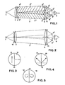
- FIG. 1 shows a first embodiment of a light barrier,
- FIG. 2 shows a second embodiment of a light barrier,
- FIG. 3 shows polarization filters with linear polarization,
- FIG. 4 shows polarization filters with linear polarization, the plane of polarization being inclined by approximately 45 ° to the horizontal.
- FIG. 5 shows polarization filters with circular polarization,
- Figure 6 shows an evaluation circuit.
a
Durch dieses geteilte Polarisationsfilter wird die Strahlung in der Ueberwachungsstrecke 3 in zwei Strahlungszweige 31 und 32 mit entsprechend unterschiedlicher Polarisation geteilt. Im dargestellten Beispiel, bei Verwendung einer einfachen Sammellinse 2 überdecken sich beide Strahlungs- zweige teilweise, aber nicht vollständig, und sind nebeneinander, vorzugsweise horizontal nebeneinander, angeordnet.This divided polarization filter divides the radiation in the
Die Strahlung aus den beiden Strahlungszweigen 31 und 32 gelangt über ein weiteres in zwei Hälften geteiltes und bezüglich der Polarisationsart genau dem ersten Filter 4 entsprechendes Polisarisationsfilter 5 und zwei Halblinsen 61 und 62, die durch eine Blende 7 getrennt sind und dieselbe Trennebene aufweisen wie das Polarisationsfilter 5, auf je ein Sensorelement 8 1 bzw. 82 eines Dual-Strahlungssensors 8, dessen spektrale Empfindlichkeit der Strahlungsquelle 1 entspricht, fokussiert.The radiation from the two
Obwohl sich die beiden Strahlungszweige 3l und 32 im mittleren Bereich etwas überschneiden, erhält dabei das Strahlungssensor-Element 81 ausschliesslich Strahlung aus dem Zweig 31, die vom Polarisationsfilterteil 41 durchgelassen wurde, da der Anteil, der von der anderen Hälfte 42 geliefert wurde, durch das Polarisationsfilterteil 51 absorbiert wird, und umgekehrt gelangt auf das Sensorelement 8 2 ausschliesslich Strahlung vom Filterteil 42 aus dem Strahlungszweig 3 2.Although the two
Auf diese Weise wird eine saubere Trennung beider Strahlungszweige erreicht, auch wenn nur relativ einfache und kostengünstige optische Elemente verwendet werden, so dass sich auf besonders einfache Weise eine besonders grosse nutzbare Reichweite der Lichtschranke erreichen lässt, ohne dass die unvermeidliche Divergenz der Strahlungszweige störend wirkte Selbstverständlich können statt einfacher Sammellinsen jedoch auch komplizierter aufgebaute Optiken mit besserer Präzision verwendet werden, mit denen die beiden Strahlungszweige noch besser voneinander getrennt gehalten werden können und somit die Reichweite der Lichtschranke und ihre Verwendbarkeit unter ungünstigen Wetterbedingungen weiter verbesserbar sind.In this way, a clean separation of the two radiation branches is achieved, even if only relatively simple and inexpensive optical elements are used, so that a particularly large usable range of the light barrier can be achieved in a particularly simple manner, without the inevitable divergence of the radiation branches having a disruptive effect, of course Instead of simple converging lenses, however, it is also possible to use more complex optics with better precision, with which the two radiation branches can be kept even better separated from one another and thus the range of the light barrier and its usability under unfavorable weather conditions can be further improved.
Die beiden Sensorelemente 8l und 82 sind an eine Auswerteschaltung 9 angeschlossen, die z.B. als Differenzschaltung ausgebildet ist und ein Signal entsprechend dem Unterschied der Bestrahlung beider Elemente abgibt. Durch eine unpolarisierte oder in anderer Weise polarisierte Fremdstrahlung, z.3. Sonnen- oder Tageslicht, werden beide Sensorelemente in gleicher Weise von Strahlung beaufschlagt und die Auswerteschaltung 9 gibt kein Signal ab, d.h. Fremdstrahlung dieser Art wird automatisch eliminiert. Bei Auftreten von strahlungsstreuendem Nebel in der Ueberwachungsstrecke 3 wird ebenfalls die Bestrahlung beider Sensorelemente 81,82 in gleicher Weise beeinflusst, so dass auch hier keine Differenz auftritt und die Differenzschaltung 9 kein Signal weitergibt. Es kann also auch unter ungünstigen Umständen, d.h. bei Anwesenheit von Fremdstrahlung, bei Nebel oder Regen, und bei sehr grosser Reichweite oder Ueberwachungsstreckenlänge mit unverminderter oder sogar noch verbesserter Empfindlichkeit gearbeitet werden, ohne dass die Lichtschranke unempfindlich wird oder ein fehlerhaftes Signal gibt. Ein echter Eindringling wird dagegen die beiden räumlich gegeneinander versetzten Strahlungszweige 3 1, 3 2 nacheinander durchqueren und dabei je ein Differenzsignal erzeugen, d.h. ein Eindringling wird in jedem Fall mit grosser Sicherheit ein Alarmsignal auslösen. Die Nachweissicherheit und die Selektivität für einen Eindringling kann dabei noch dadurch verbessert werden, dass die Auswerteschaltung so ausgebildet wird, dass die von den beiden Sensorelemente 81 und 82 gelieferten Signale mit einer bestimmten Zeitdifferenz zueinander auftreten müssen, z.B. innerhalb eines vorgegebenen Zeitfensters, und mit einer bestimmten Intensität, oder mit anderen geeigneten Kriterien, um einen Alarm auslösen zu können. Aus den Signalen können mit einer geeignet ausgebildeten Schaltung auch noch weitere Informationen, z.B. über Grösse und Geschwindigkeit des detektierten Objektes, gewonnen werden.The two sensor elements 8l and 8 2 are connected to an
Bei dem in Figur 2 dargestellten Ausführungsbeispiel, bei dem identische Elemente mit den gleichen Bezugszeichen versehen sind, wie in der vorstehend beschriebenen Lichtschranke, ist das erste, hälftig geteilte Polarisationsfilter 10 zwischen der Strahlungsquelle 1 und der Linse 2 angeordnet, und das weitere Polarisationsfilter 11 zwischen den Halblinsen 61, 62 und dem Strahlungssensor 8.In the embodiment shown in Figure 2, in which identical elements are provided with the same reference numerals as in the light barrier described above, the first, half-divided
Stattdessen können die Polarisationsfilter auch direkt auf die Oberflächen, d.h. die Vorderseite oder die Rückseite der Linse 2, bzw. der Halblinsen 61 und 6 2 aufgebracht sein. Es ist auch möglich, die Linse 2 aus unterschiedlich polarisierten Teilen aus polarisierendem Material auszubilden oder diese Linse Zonen mit unterschiedlicher Polarisation zusammenzusetzen, wobei jeweils die empfängerseitigen Linsen analog ausgeführt und aufgebaut sind. S t a can ttdessen the polarization filters directly on the surfaces, ie the front or the back of the
Auch weitere Abwandlungen sind im Rahmen der Erfindung möglich. Statt einer Anordnung der Strahlungszweige horizontal nebeneinder können diese z.B. auch in anderer Weise vorgesehen sein. So können diese etwa als zentraler Teil und als diesen konzentrisch umgebenden Ring ausgeführt sein, und der Strahlungssensor entsprechend mit einer strahlungsempfindlichen Zone im Zentrum und einer diese ringförmig umgebenden zweiten strahlungsempfindlichen Zone. Damit muss bei der Montage nicht mehr auf die Orientierung geachtet werden.Further modifications are also possible within the scope of the invention. Instead of arranging the radiation branches horizontally next to each other, they can e.g. can also be provided in a different way. For example, they can be designed as a central part and as a ring concentrically surrounding them, and the radiation sensor accordingly with a radiation-sensitive zone in the center and a second radiation-sensitive zone surrounding it in a ring. This means that you no longer have to pay attention to the orientation during assembly.
Figur 3 zeigt ein Polarisationsfilter 4 oder 5, bzw. 10 oder 11, das durch eine vertikale Trennlinie 12 in zwei Hälften 13 und 14 mit unterschiedlicher Polarisation unterteilt wird. Die Polarisation ist in beiden Hälften linear, und zwar in einer Hälfte 13 in vertikaler und in der anderen Hälfte orthogonal dazu in horizontaler Richtung. Beide Polarisationsarten sind also voneinander unabhängig, d.h. derart polarisierte Strahlungen löschen sich gegenseitig aus.Figure 3 shows a
Bei dem in Figur 4 dargestellten Polarisationsfilter ist ebenfalls eine lineare Polarisation vorgesehen, jedoch sind die beiden Polarisationsrichtungen in den Hälften 13 und 14 etwa 45° gegen die Horizontale oder Vertikale geneigt. Da natürliche Fremdstrahlungen, z.B. Sonnenstrahlung oder Himmelslicht, wenn überhaupt nennenswert, dann fast imner bevorzugt entweder vertikal oder horizontal polarisiert sind, so ist deren Einfluss auf die beiden nur für 45°-polarisierte Strahlung sensibilisierten Sensorelemente gleich und wird durch die Auswerteschaltung eliminiert.In the polarization filter shown in Figure 4, a linear polarization is also provided, but the two directions of polarization in the
Bei der in Figur 5 gezeigten Ausführungsform eines Polarisationsfilters sind die beiden Hälften 13 und 14 nicht linear, sondern zirkular polarisierend ausgebildet. Die beiden Hälften haben dabei einen entgegengesetzten Drehsinn, d.h. der Teil 13 ist linksdrehend, und der Teil 14 rechtsdrehend zirkular polarisierend ausgebildet. Auch hierdurch können Fremdstrahlungen weitgehend eliminiert oder unwirksam gemacht werden.In the embodiment of a polarization filter shown in FIG. 5, the two
Wie bereits erwähnt, muss die Trennungslinie 12 der beiden Hälften 13 und 14 der Polarisationsfilter 4 und 5 nicht unbedingt vertikal verlaufen. Durch die Aufteilung muss jedoch gewährleistet sein, dass Stahlungszweige gebildet werden, die von einem Eindringling nacheinander mit einer gewissen messbaren Zeitdifferenz durchquert werden.As already mentioned, the dividing
Figur 6 zeigt ein Beispiel einer geeigneten Auswerteschaltung, bei dem die beiden Sensorelemente 81 und 82 als Phototransistoren Ph ausgebildet sind, die mit zugehörigen Widerständen in Emitterfolgerschaltung liegen und ihr Ausgangssignal über je einen Vorverstärker 15, bzw. 16 je einer Sample & Hold-Schaltung zuleiten. Da die Strahlungsquelle aus Gründen der Störsicherheit vorzugsweise als Impulsstrahler mit einer bestimmten Impulsfrequenz betrieben wird, und die Vorverstärker entsprechend frequenzselektiv ausgebildet sind, speichern die beiden Sample & Hold-Schaltungen 17 und 18 die Maxima der Impulse für eine kurze Zeit und geben sie an eine Differenzschal- tuna 19 weiter, und liefern andererseits an eine Ueberwachungsschaltung 20 ein Signal, falls die Eingangsimpulse ausbleiben oder deren Intensität unter eine gegebene Schwelle sinkt, und zeigen eine Störung oder Sabotageversuch an.FIG. 6 shows an example of a suitable evaluation circuit, in which the two sensor elements 8 1 and 8 2 are designed as phototransistors Ph, which are connected to the resistor E with associated resistors and each have their output signal via a
Da der positive Eingang der Differenzschaltung 19 von dem einen Sensorelement 6 und der negative Eingang vom anderen Sensorelement 8 2 angesteuert wird, erscheint am Ausgang der Differenzschaltung 19 ein positives Signal, bzw. ein negatives Signal, je nachdem, welches Sensorelement eine Bestrahlungsänderung erfahren hat. Werden die beiden Strahlungszweige nacheinander von einem Objekt durchquert, so erscheint also nacheinander in kurzem Zeitabstand ein positiver und ein negativer Impuls. Die Ausgangssignale der Differenzschaltung 19 werden je einem positiven und negativen Schwellenwertdetektor 21, 22 zugeführt, die die Signale an zwei kreuzweise geschaltete ODER-Tore 23, 24 weiterleiten, sofern deren Intensität die vorgegebenen Schwellenwerte übersteigen. Die ODER-Tore 23 und 24 geben bei Auftreten eines ersten positiven oder negativen Impulses einen Startimpuls an den Starteingang eines Zählers und Zeitfensterkomparators 25 und den zweiten positiven oder negativen Impuls an den Stopeingang dieses Zählers 25. Dieser ist nun so ausgebildet, dass er ein Signal an einen Alarmsignalgeber 26 abgibt, wenn der Zweite oder Stopimpuls innerhalb eines vorgegebenen Zeitfensters liegt, d.h. wenn der zweite Impuls frühestens nach einer bestimmten Minimalzeit, aber spätestens nach einer vorgegebenen Maximalzeit eintrifft. Die Minimalzeit kann auch Null gewählt werden, wenngleich eine endliche Minimalzeit eine grössere Sicherheit bietet. Nach Ablauf der vorgegebenen Maximalzeit wird der Stopeingang blockiert und der Zähler automatisch zurückgestellt, so dass die Schaltung wiederum betriebsbereit ist.Since the positive input of the
Es versteht sich, dass statt der beschriebenen Schaltung auch andere Schaltungen mit analoger und äquivalenter Funktion verwendet werden können.It goes without saying that, instead of the circuit described, other circuits with an analog and equivalent function can also be used.
Claims (10)
Priority Applications (1)
| Application Number | Priority Date | Filing Date | Title |
|---|---|---|---|
| AT86105818T ATE64023T1 (en) | 1985-04-30 | 1986-04-26 | PHOTOELECTRIC BARRIER. |
Applications Claiming Priority (2)
| Application Number | Priority Date | Filing Date | Title |
|---|---|---|---|
| CH1825/85 | 1985-04-30 | ||
| CH1825/85A CH667340A5 (en) | 1985-04-30 | 1985-04-30 | PHOTOELECTRIC BARRIER. |
Publications (3)
| Publication Number | Publication Date |
|---|---|
| EP0200186A2 true EP0200186A2 (en) | 1986-11-05 |
| EP0200186A3 EP0200186A3 (en) | 1987-01-21 |
| EP0200186B1 EP0200186B1 (en) | 1991-05-29 |
Family
ID=4219477
Family Applications (1)
| Application Number | Title | Priority Date | Filing Date |
|---|---|---|---|
| EP86105818A Expired - Lifetime EP0200186B1 (en) | 1985-04-30 | 1986-04-26 | Light barrier |
Country Status (5)
| Country | Link |
|---|---|
| US (1) | US4734575A (en) |
| EP (1) | EP0200186B1 (en) |
| AT (1) | ATE64023T1 (en) |
| CH (1) | CH667340A5 (en) |
| DE (1) | DE3679443D1 (en) |
Cited By (2)
| Publication number | Priority date | Publication date | Assignee | Title |
|---|---|---|---|---|
| DE3733656C1 (en) * | 1987-10-05 | 1989-02-02 | Hoermann Kg | Retro-reflective sensor |
| EP0388352A1 (en) * | 1989-03-15 | 1990-09-19 | Elesta Ag Elektronik | One way light barrier arrangement |
Families Citing this family (13)
| Publication number | Priority date | Publication date | Assignee | Title |
|---|---|---|---|---|
| DE3641926C1 (en) * | 1986-12-09 | 1988-04-28 | Sick Optik Elektronik Erwin | Autocollimation light curtain |
| NL8902314A (en) * | 1989-09-15 | 1991-04-02 | Michiel Kassies | METHOD AND APPARATUS FOR DETECTING AN ARTICLE |
| US5955854A (en) * | 1992-09-29 | 1999-09-21 | Prospects Corporation | Power driven venting of a vehicle |
| EP0951653B1 (en) * | 1997-11-07 | 2003-01-02 | Leuze electronic GmbH + Co. | Optoelectronic device |
| DE102004017183A1 (en) * | 2004-04-07 | 2005-11-10 | Siemens Ag | Overall system, especially medical equipment |
| US8970374B2 (en) * | 2008-04-17 | 2015-03-03 | Shilat Optronics Ltd | Intrusion warning system |
| EP2359593B1 (en) * | 2008-11-25 | 2018-06-06 | Tetravue, Inc. | Systems and methods of high resolution three-dimensional imaging |
| JP5458813B2 (en) * | 2009-11-10 | 2014-04-02 | オムロン株式会社 | Photoelectric sensor |
| EP2813868B1 (en) * | 2013-06-11 | 2021-08-04 | Rockwell Automation Switzerland GmbH | Method for synchronizing optical units of a photoelectric barrier and light curtain |
| WO2015164868A1 (en) | 2014-04-26 | 2015-10-29 | Tetravue, Inc. | Method and system for robust and extended illumination waveforms for depth sensing in 3d imaging |
| DE102014013326A1 (en) * | 2014-09-15 | 2016-03-17 | Imos Gubela Gmbh | Optical sensor system |
| KR20190003480A (en) | 2016-02-29 | 2019-01-09 | 테트라뷰 인코포레이티드 | 3D imaging system and method |
| US11212512B2 (en) | 2017-12-28 | 2021-12-28 | Nlight, Inc. | System and method of imaging using multiple illumination pulses |
Citations (5)
| Publication number | Priority date | Publication date | Assignee | Title |
|---|---|---|---|---|
| US2457502A (en) * | 1944-08-09 | 1948-12-28 | Shepherd Judson O'd | Signal system employing polarized light |
| US3440427A (en) * | 1966-04-12 | 1969-04-22 | Philips Corp | Remote control system with a unitary cell bridge circuit |
| GB1214981A (en) * | 1967-05-05 | 1970-12-09 | John Horrocks | Control means using light filters |
| DE1946993A1 (en) * | 1969-09-17 | 1971-03-25 | Sick Erwin Fa | Light barrier for analog measuring purposes |
| US4342987A (en) * | 1979-09-10 | 1982-08-03 | Rossin Corporation | Intruder detection system |
Family Cites Families (3)
| Publication number | Priority date | Publication date | Assignee | Title |
|---|---|---|---|---|
| US4333008A (en) * | 1975-04-21 | 1982-06-01 | Sanders Associates, Inc. | Polarization coded doublet laser detection system |
| FR2347666A1 (en) * | 1976-04-09 | 1977-11-04 | France Etat | AUTOMATIC TWO WAVELENGTH PHOTOELASTICIMETER |
| US4339660A (en) * | 1980-05-15 | 1982-07-13 | Erwin Sick Gmbh Optik-Elektronik | Reflection light barrier apparatus for recognizing both strongly and weakly reflecting objects |
-
1985
- 1985-04-30 CH CH1825/85A patent/CH667340A5/en not_active IP Right Cessation
-
1986
- 1986-04-26 DE DE8686105818T patent/DE3679443D1/en not_active Expired - Fee Related
- 1986-04-26 AT AT86105818T patent/ATE64023T1/en not_active IP Right Cessation
- 1986-04-26 EP EP86105818A patent/EP0200186B1/en not_active Expired - Lifetime
- 1986-04-28 US US06/856,834 patent/US4734575A/en not_active Expired - Fee Related
Patent Citations (5)
| Publication number | Priority date | Publication date | Assignee | Title |
|---|---|---|---|---|
| US2457502A (en) * | 1944-08-09 | 1948-12-28 | Shepherd Judson O'd | Signal system employing polarized light |
| US3440427A (en) * | 1966-04-12 | 1969-04-22 | Philips Corp | Remote control system with a unitary cell bridge circuit |
| GB1214981A (en) * | 1967-05-05 | 1970-12-09 | John Horrocks | Control means using light filters |
| DE1946993A1 (en) * | 1969-09-17 | 1971-03-25 | Sick Erwin Fa | Light barrier for analog measuring purposes |
| US4342987A (en) * | 1979-09-10 | 1982-08-03 | Rossin Corporation | Intruder detection system |
Cited By (4)
| Publication number | Priority date | Publication date | Assignee | Title |
|---|---|---|---|---|
| DE3733656C1 (en) * | 1987-10-05 | 1989-02-02 | Hoermann Kg | Retro-reflective sensor |
| EP0310932A2 (en) * | 1987-10-05 | 1989-04-12 | HàRmann Kg Bielefeld | Light barrier with reflector |
| EP0310932A3 (en) * | 1987-10-05 | 1991-02-06 | HàRmann Kg Bielefeld | Light barrier with reflector |
| EP0388352A1 (en) * | 1989-03-15 | 1990-09-19 | Elesta Ag Elektronik | One way light barrier arrangement |
Also Published As
| Publication number | Publication date |
|---|---|
| EP0200186B1 (en) | 1991-05-29 |
| DE3679443D1 (en) | 1991-07-04 |
| ATE64023T1 (en) | 1991-06-15 |
| EP0200186A3 (en) | 1987-01-21 |
| US4734575A (en) | 1988-03-29 |
| CH667340A5 (en) | 1988-09-30 |
Similar Documents
| Publication | Publication Date | Title |
|---|---|---|
| EP0200186B1 (en) | Light barrier | |
| EP0360126B2 (en) | Operation method for an optical smoke detector and smoke detector for carrying out the method | |
| DE2824583C3 (en) | Reflective light barrier for the detection of highly reflective objects within a monitoring path traversed by a bundle of rays | |
| EP0328709B1 (en) | Light barrier | |
| DE19707417C2 (en) | Optoelectronic device | |
| DE3530646A1 (en) | AREA SECURING | |
| DE2754139A1 (en) | SMOKE DETECTOR | |
| EP0283538A1 (en) | Detector apparatus | |
| EP0926646A1 (en) | Optical smoke detector | |
| DE3733656C1 (en) | Retro-reflective sensor | |
| CH671838A5 (en) | ||
| DE202007007290U1 (en) | Optoelectronic sensor arrangement | |
| DE19913156B4 (en) | Optoelectronic device | |
| DE2703225A1 (en) | Beam interruption smoke detector - has LED's with ring connected power supply arranged round room to focus beams on to central light sensitive receiver | |
| DE10016892B4 (en) | Optoelectronic device | |
| WO2020064935A1 (en) | Scattered light smoke detector having a two-color led, a photosensor, and a wavelength-selective polarizer connected upstream of the photosensor or connected downstream of the two-color led, and suitable use of such a polarizer | |
| DE3518262C2 (en) | ||
| DE8609515U1 (en) | Device for sabotage monitoring on an IR motion detector | |
| DE4333911A1 (en) | Optical smoke detector | |
| DE2262118A1 (en) | FAILURE-PROOF ALARM SYSTEM | |
| DE3728354A1 (en) | Light-barrier arrangement | |
| DE19614872C1 (en) | Light sensor for detecting object in monitoring region on detection plane | |
| EP1265205B1 (en) | Linear smoke detector | |
| DE2823957A1 (en) | Light absorption smoke detector - is insensitive to position of light beam reflectors due to multi-facet surface of remote reflector | |
| EP0133990B1 (en) | Smoke sensor arrangement operating by the extinguish principle, and fire assembly having such a smoke sensor arrangement |
Legal Events
| Date | Code | Title | Description |
|---|---|---|---|
| PUAI | Public reference made under article 153(3) epc to a published international application that has entered the european phase |
Free format text: ORIGINAL CODE: 0009012 |
|
| 17P | Request for examination filed |
Effective date: 19860426 |
|
| AK | Designated contracting states |
Kind code of ref document: A2 Designated state(s): AT BE CH DE FR GB IT LI NL SE |
|
| PUAL | Search report despatched |
Free format text: ORIGINAL CODE: 0009013 |
|
| AK | Designated contracting states |
Kind code of ref document: A3 Designated state(s): AT BE CH DE FR GB IT LI NL SE |
|
| 17Q | First examination report despatched |
Effective date: 19890912 |
|
| GRAA | (expected) grant |
Free format text: ORIGINAL CODE: 0009210 |
|
| AK | Designated contracting states |
Kind code of ref document: B1 Designated state(s): AT BE CH DE FR GB IT LI NL SE |
|
| PG25 | Lapsed in a contracting state [announced via postgrant information from national office to epo] |
Ref country code: SE Effective date: 19910529 Ref country code: NL Effective date: 19910529 Ref country code: BE Effective date: 19910529 |
|
| REF | Corresponds to: |
Ref document number: 64023 Country of ref document: AT Date of ref document: 19910615 Kind code of ref document: T |
|
| ITF | It: translation for a ep patent filed |
Owner name: JACOBACCI & PERANI S.P.A. |
|
| REF | Corresponds to: |
Ref document number: 3679443 Country of ref document: DE Date of ref document: 19910704 |
|
| ET | Fr: translation filed | ||
| GBT | Gb: translation of ep patent filed (gb section 77(6)(a)/1977) | ||
| NLV1 | Nl: lapsed or annulled due to failure to fulfill the requirements of art. 29p and 29m of the patents act | ||
| PLBE | No opposition filed within time limit |
Free format text: ORIGINAL CODE: 0009261 |
|
| STAA | Information on the status of an ep patent application or granted ep patent |
Free format text: STATUS: NO OPPOSITION FILED WITHIN TIME LIMIT |
|
| PG25 | Lapsed in a contracting state [announced via postgrant information from national office to epo] |
Ref country code: AT Effective date: 19920426 |
|
| 26N | No opposition filed | ||
| PGFP | Annual fee paid to national office [announced via postgrant information from national office to epo] |
Ref country code: FR Payment date: 19940309 Year of fee payment: 9 |
|
| PGFP | Annual fee paid to national office [announced via postgrant information from national office to epo] |
Ref country code: GB Payment date: 19940316 Year of fee payment: 9 |
|
| PGFP | Annual fee paid to national office [announced via postgrant information from national office to epo] |
Ref country code: DE Payment date: 19940406 Year of fee payment: 9 |
|
| PG25 | Lapsed in a contracting state [announced via postgrant information from national office to epo] |
Ref country code: GB Effective date: 19950426 |
|
| PGFP | Annual fee paid to national office [announced via postgrant information from national office to epo] |
Ref country code: CH Payment date: 19950517 Year of fee payment: 10 |
|
| GBPC | Gb: european patent ceased through non-payment of renewal fee |
Effective date: 19950426 |
|
| PG25 | Lapsed in a contracting state [announced via postgrant information from national office to epo] |
Ref country code: FR Effective date: 19951229 |
|
| PG25 | Lapsed in a contracting state [announced via postgrant information from national office to epo] |
Ref country code: DE Effective date: 19960103 |
|
| REG | Reference to a national code |
Ref country code: FR Ref legal event code: ST |
|
| PG25 | Lapsed in a contracting state [announced via postgrant information from national office to epo] |
Ref country code: LI Effective date: 19960430 Ref country code: CH Effective date: 19960430 |
|
| REG | Reference to a national code |
Ref country code: CH Ref legal event code: PL |
|
| PG25 | Lapsed in a contracting state [announced via postgrant information from national office to epo] |
Ref country code: IT Free format text: LAPSE BECAUSE OF NON-PAYMENT OF DUE FEES;WARNING: LAPSES OF ITALIAN PATENTS WITH EFFECTIVE DATE BEFORE 2007 MAY HAVE OCCURRED AT ANY TIME BEFORE 2007. THE CORRECT EFFECTIVE DATE MAY BE DIFFERENT FROM THE ONE RECORDED. Effective date: 20050426 |