EP0200186A2 - Barrière photoélectrique - Google Patents
Barrière photoélectrique Download PDFInfo
- Publication number
- EP0200186A2 EP0200186A2 EP86105818A EP86105818A EP0200186A2 EP 0200186 A2 EP0200186 A2 EP 0200186A2 EP 86105818 A EP86105818 A EP 86105818A EP 86105818 A EP86105818 A EP 86105818A EP 0200186 A2 EP0200186 A2 EP 0200186A2
- Authority
- EP
- European Patent Office
- Prior art keywords
- radiation
- light barrier
- polarization
- barrier according
- sensor
- Prior art date
- Legal status (The legal status is an assumption and is not a legal conclusion. Google has not performed a legal analysis and makes no representation as to the accuracy of the status listed.)
- Granted
Links
- 230000004888 barrier function Effects 0.000 title claims abstract description 26
- 230000005855 radiation Effects 0.000 claims abstract description 98
- 230000010287 polarization Effects 0.000 claims abstract description 49
- 238000011156 evaluation Methods 0.000 claims description 16
- 238000012544 monitoring process Methods 0.000 abstract description 6
- 230000035945 sensitivity Effects 0.000 abstract description 5
- 241000219739 Lens Species 0.000 description 12
- 230000036039 immunity Effects 0.000 description 3
- 240000004322 Lens culinaris Species 0.000 description 2
- 230000002411 adverse Effects 0.000 description 2
- 230000003287 optical effect Effects 0.000 description 2
- 230000003595 spectral effect Effects 0.000 description 2
- 241001295925 Gegenes Species 0.000 description 1
- 229910000831 Steel Inorganic materials 0.000 description 1
- 238000011109 contamination Methods 0.000 description 1
- 230000001419 dependent effect Effects 0.000 description 1
- 238000001514 detection method Methods 0.000 description 1
- 238000011161 development Methods 0.000 description 1
- 230000018109 developmental process Effects 0.000 description 1
- 230000000694 effects Effects 0.000 description 1
- 239000000463 material Substances 0.000 description 1
- 239000003595 mist Substances 0.000 description 1
- 238000012986 modification Methods 0.000 description 1
- 230000004048 modification Effects 0.000 description 1
- 238000000926 separation method Methods 0.000 description 1
- 239000010959 steel Substances 0.000 description 1
- 238000012549 training Methods 0.000 description 1
- 230000003313 weakening effect Effects 0.000 description 1
Images

Classifications
-
- G—PHYSICS
- G08—SIGNALLING
- G08B—SIGNALLING OR CALLING SYSTEMS; ORDER TELEGRAPHS; ALARM SYSTEMS
- G08B13/00—Burglar, theft or intruder alarms
- G08B13/18—Actuation by interference with heat, light, or radiation of shorter wavelength; Actuation by intruding sources of heat, light, or radiation of shorter wavelength
- G08B13/181—Actuation by interference with heat, light, or radiation of shorter wavelength; Actuation by intruding sources of heat, light, or radiation of shorter wavelength using active radiation detection systems
- G08B13/183—Actuation by interference with heat, light, or radiation of shorter wavelength; Actuation by intruding sources of heat, light, or radiation of shorter wavelength using active radiation detection systems by interruption of a radiation beam or barrier
Definitions
- the invention relates to a light barrier with a radiation source and a radiation sensor acted upon by its radiation with at least two sensor elements, means for polarizing the radiation and radiation filters differently polarized in front of the two sensor elements being provided, and the two sensor elements being connected to one another in an evaluation circuit, which different radiation of the two sensor elements emits a signal.
- Such light barriers are known for example from DE 1 934 321 or from DE 2 014 107 and are preferably used for intrusion protection.
- the evaluation circuit triggers an alarm signal.
- a polarization of the radiation emanating from the radiation source and the arrangement of a similar polarization filter in front of one of the sensor elements, the other sensor element absorbing radiation that is not polarized or polarized differently, ensures that the evaluation circuit does not emit an output signal if the radiation sensor is exposed to external radiation, for example solar radiation or Scattered light is struck, the polarization of which deviates from the type of polarization of the light barrier radiation or which is unpolarized, which should normally be the case, since in this case both sensor elements are acted upon equally.
- Such light barriers can also be used for outdoor applications in daylight.
- the immunity to interference can be further improved by using alternating radiation of a specific frequency and tuning the evaluation circuit to this frequency.
- a synchronization of the radiation source and the evaluation circuit has also already been described.
- the radiation source must be connected to the radiation sensor or the circuit, so that usually an autocollimation arrangement with a spatially adjacent radiation source and radiation sensors, as well as a reflector arranged at a distance therefrom and very sensitive to contamination and misalignment is provided.
- the range of these light barriers i.e. the safely manageable length of the surveillance route is therefore rather limited.
- the invention has for its object to eliminate the aforementioned disadvantages of the prior art and in particular to create a light barrier, which also Outdoor applications and the presence of extraneous light as well as weather-related radiation scattering with a greater range and improved interference immunity can reliably detect an object to be detected, for example an intruder with greater sensitivity.
- this object is achieved in that the radiation from two spatially mutually offset radiating arms with different, independent of polarization, and in that the radiation from the two S trahlungszweigen with different polarization to a respective sensor element is passed.
- a different, mutually independent polarization in the two radiation branches can be achieved, for example, in that both radiation branches are linearly polarized by means of suitable polarization filters after the radiation source, specifically orthogonally to one another.
- the polarization planes are chosen to be inclined at 45 ° to the horizontal or vertical in order to render elliptically polarized extraneous light with vertical and horizontal main axes, for example sunlight, ineffective, since this affects both sensor elements equally at an inclination of 45 °.
- Circular polarization with the opposite direction of rotation can also be used with advantage.
- a corresponding polarization filter combination is then to be provided in front of the radiation sensor, which, if appropriate in cooperation with suitable optical elements, directs the polarized radiation from one radiation branch to one sensor element and the radiation from the other radiation branch to the other sensor element.
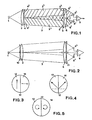
- This divided polarization filter divides the radiation in the monitoring section 3 into two radiation branches 3 1 and 3 2 with correspondingly different polarization.
- the two S overlap trahlungs- branches partially, but not completely, and are juxtaposed side by side, disposed preferably horizontally.
- the radiation from the two radiation branches n 3 1 and 3 2 passes through a further polarization filter 5, which is divided into two halves and corresponds exactly to the first filter 4 with respect to the type of polarization, and two half lenses 6 1 and 6 2, which are separated by an aperture 7 and the same separating plane having as the polarizing filter 5, to a sensor element e j 8 1 and 8 2 of a dual-radiation sensor 8, the spectral sensitivity of the radiation source 1 corresponds focused.
- the radiation sensor element receives 8 1 exclusively radiation from the branch 3 1, which was transmitted by the P olarisationsfilterteil 4 1, since the proportion of the other half 4 was delivered 2, is absorbed by the polarization filter part 5 1, and vice versa reaches the sensor element 8 2 exclusively radiation from the filter member 4 2 of the radiation path 3.
- the two sensor elements 8l and 8 2 are connected to an evaluation circuit 9, for example, is formed as a differential circuit and a signal corresponding to the difference in the irradiation emits both elements.
- an evaluation circuit 9 for example, is formed as a differential circuit and a signal corresponding to the difference in the irradiation emits both elements.
- an unpolarized or otherwise polarized external radiation z.3.
- Sunlight or daylight radiation is applied to both sensor elements in the same way and the evaluation circuit 9 does not emit a signal, ie extraneous radiation of this type is automatically eliminated. If radiation-scattering mist occurs in the monitoring section 3, the irradiation of both sensor elements 8 1 , 8 2 is likewise influenced in the same way, so that no difference occurs here and the differential circuit 9 does not transmit a signal.
- the security of detection and the selectivity for an intruder can be further improved by designing the evaluation circuit in such a way that the signals supplied by the two sensor elements 8 1 and 8 2 must occur with a certain time difference from one another, for example within a predetermined time window, and with a certain intensity, or with other suitable criteria to be able to trigger an alarm.
- the signals supplied by the two sensor elements 8 1 and 8 2 must occur with a certain time difference from one another, for example within a predetermined time window, and with a certain intensity, or with other suitable criteria to be able to trigger an alarm.
- further information can be obtained from the signals, for example about the size and speed of the detected object.
- the first, half-divided polarization filter 10 is arranged between the radiation source 1 and the lens 2, and the further polarization filter 11 between the half lenses 6 1 , 6 2 and the radiation sensor 8.
- S t a can ttange the polarization filters directly on the surfaces, ie the front or the back of the lens 2, and the half lenses 1 and 6 to be brought to 6. 2 It is also possible to form the lens 2 from differently polarized parts made of polarizing material or to assemble this lens into zones with different polarization, the respective lenses on the receiver side being designed and constructed analogously.
- the radiation branches can e.g. can also be provided in a different way.
- they can be designed as a central part and as a ring concentrically surrounding them, and the radiation sensor accordingly with a radiation-sensitive zone in the center and a second radiation-sensitive zone surrounding it in a ring. This means that you no longer have to pay attention to the orientation during assembly.
- Figure 3 shows a polarization filter 4 or 5, or 10 or 11, which is divided by a vertical dividing line 12 into two halves 13 and 14 with different polarization.
- the polarization is linear in both halves, namely in one half 13 in the vertical direction and in the other half orthogonally to it in the horizontal direction. Both types of polarization are therefore independent of each other, i.e. Radiations polarized in this way cancel each other out.
- a linear polarization is also provided, but the two directions of polarization in the halves 13 and 14 are inclined approximately 45 ° to the horizontal or vertical.
- D a natural extraneous radiation, e.g. solar radiation or sky light, if any, then almost are preferably polarized either vertically or horizontally, their influence on the two sensor elements only sensitized to 45 ° polarized radiation is the same and is eliminated by the evaluation circuit.
- the two halves 13 and 14 are not linear, but circularly polarizing.
- the two halves have an opposite direction of rotation, i.e. the part 13 is counterclockwise and the part 14 clockwise circular polarizing. This also largely eliminates external radiation or makes it ineffective.
- the dividing line 12 of the two halves 13 and 14 of the polarization filters 4 and 5 does not necessarily have to run vertically. However, the division must ensure that steel branches are formed, which are penetrated by an intruder in succession with a certain measurable time difference.
- FIG. 6 shows an example of a suitable evaluation circuit, in which the two sensor elements 8 1 and 8 2 are designed as phototransistors Ph, which are connected to the resistor E with associated resistors and each have their output signal via a preamplifier 15 or 16 a sample and hold -Supply circuit.
- the radiation source is preferably operated as a pulse emitter with a certain pulse frequency for reasons of interference immunity, and the preamplifiers are designed to be frequency-selective
- the two sample and hold circuits 17 and 18 store the maxima of the pulses for a short time and give them to a D ifferenceschal- tuna 19, and on the other hand deliver a signal to a monitoring circuit 20 if the input pulses fail or their intensity drops below a given threshold, and indicate a fault or attempted sabotage.
- the positive input of the differential circuit 19 is controlled by one sensor element 6 and the negative input by the other sensor element 8 2, a positive signal or a negative signal appears at the output of the differential circuit 19, depending on which sensor element has undergone a change in irradiation. If an object crosses the two radiation branches one after the other, a positive and a negative pulse appear in succession at short intervals.
- the output signals of the differential circuit 19 are each fed to a positive and negative threshold value detector 21, 22, which forward the signals to two cross-connected OR gates 23, 24, provided that their intensity exceeds the predetermined threshold values.
- the OR gates 23 and 24 indicate the occurrence of a first positive or negative pulse a start pulse to the S tarteingang a counter and Zeitkrokomparators 25 and the second positive or negative pulse to the S topeingang this counter 25.
- This is now so formed to a signal to an alarm signal generator 26 outputs, when the second or stop pulse is within a predetermined Z eitgras, ie when the second pulse, but arrives at the earliest after a certain minimum period not later than a predetermined maximum time.
- the minimum time can also be chosen to be zero, although a finite minimum time offers greater security.
Priority Applications (1)
| Application Number | Priority Date | Filing Date | Title |
|---|---|---|---|
| AT86105818T ATE64023T1 (de) | 1985-04-30 | 1986-04-26 | Lichtschranke. |
Applications Claiming Priority (2)
| Application Number | Priority Date | Filing Date | Title |
|---|---|---|---|
| CH1825/85A CH667340A5 (de) | 1985-04-30 | 1985-04-30 | Lichtschranke. |
| CH1825/85 | 1985-04-30 |
Publications (3)
| Publication Number | Publication Date |
|---|---|
| EP0200186A2 true EP0200186A2 (fr) | 1986-11-05 |
| EP0200186A3 EP0200186A3 (en) | 1987-01-21 |
| EP0200186B1 EP0200186B1 (fr) | 1991-05-29 |
Family
ID=4219477
Family Applications (1)
| Application Number | Title | Priority Date | Filing Date |
|---|---|---|---|
| EP86105818A Expired - Lifetime EP0200186B1 (fr) | 1985-04-30 | 1986-04-26 | Barrière photoélectrique |
Country Status (5)
| Country | Link |
|---|---|
| US (1) | US4734575A (fr) |
| EP (1) | EP0200186B1 (fr) |
| AT (1) | ATE64023T1 (fr) |
| CH (1) | CH667340A5 (fr) |
| DE (1) | DE3679443D1 (fr) |
Cited By (2)
| Publication number | Priority date | Publication date | Assignee | Title |
|---|---|---|---|---|
| DE3733656C1 (de) * | 1987-10-05 | 1989-02-02 | Hoermann Kg | Reflexionslichtschranke |
| EP0388352A1 (fr) * | 1989-03-15 | 1990-09-19 | Elesta Ag Elektronik | Dispositif pour barrière optique à une seule direction |
Families Citing this family (13)
| Publication number | Priority date | Publication date | Assignee | Title |
|---|---|---|---|---|
| DE3641926C1 (de) * | 1986-12-09 | 1988-04-28 | Sick Optik Elektronik Erwin | Autokollimationslichtvorhang |
| NL8902314A (nl) * | 1989-09-15 | 1991-04-02 | Michiel Kassies | Werkwijze en inrichting voor het detecteren van een voorwerp. |
| US5955854A (en) * | 1992-09-29 | 1999-09-21 | Prospects Corporation | Power driven venting of a vehicle |
| WO1999024850A1 (fr) * | 1997-11-07 | 1999-05-20 | Leuze Electronic Gmbh + Co. | Dispositif optoelectronique |
| DE102004017183A1 (de) * | 2004-04-07 | 2005-11-10 | Siemens Ag | Gesamtsystem, insbesondere medizinische Anlage |
| WO2009144707A1 (fr) * | 2008-04-17 | 2009-12-03 | Shilat Optronics Ltd | Système d'alarme d'intrusion |
| WO2010068499A1 (fr) | 2008-11-25 | 2010-06-17 | Tetravue, Inc. | Systèmes et procédés d'imagerie tridimensionnelle à haute résolution |
| JP5458813B2 (ja) * | 2009-11-10 | 2014-04-02 | オムロン株式会社 | 光電センサ |
| EP2813868B1 (fr) * | 2013-06-11 | 2021-08-04 | Rockwell Automation Switzerland GmbH | Procédé de synchronisation d'unités optiques d'une barrière photoélectrique et rideau de lumière |
| US10104365B2 (en) | 2014-04-26 | 2018-10-16 | Tetravue, Inc. | Method and system for robust and extended illumination waveforms for depth sensing in 3D imaging |
| DE102014013326A1 (de) * | 2014-09-15 | 2016-03-17 | Imos Gubela Gmbh | Optisches Sensorsystem |
| EP3423858B1 (fr) | 2016-02-29 | 2023-12-06 | nLIGHT, Inc. | Système et procédé d'imagerie 3d |
| US11212512B2 (en) | 2017-12-28 | 2021-12-28 | Nlight, Inc. | System and method of imaging using multiple illumination pulses |
Citations (5)
| Publication number | Priority date | Publication date | Assignee | Title |
|---|---|---|---|---|
| US2457502A (en) * | 1944-08-09 | 1948-12-28 | Shepherd Judson O'd | Signal system employing polarized light |
| US3440427A (en) * | 1966-04-12 | 1969-04-22 | Philips Corp | Remote control system with a unitary cell bridge circuit |
| GB1214981A (en) * | 1967-05-05 | 1970-12-09 | John Horrocks | Control means using light filters |
| DE1946993A1 (de) * | 1969-09-17 | 1971-03-25 | Sick Erwin Fa | Lichtschranke fuer analoge Messzwecke |
| US4342987A (en) * | 1979-09-10 | 1982-08-03 | Rossin Corporation | Intruder detection system |
Family Cites Families (3)
| Publication number | Priority date | Publication date | Assignee | Title |
|---|---|---|---|---|
| US4333008A (en) * | 1975-04-21 | 1982-06-01 | Sanders Associates, Inc. | Polarization coded doublet laser detection system |
| FR2347666A1 (fr) * | 1976-04-09 | 1977-11-04 | France Etat | Photoelasticimetre automatique a deux longueurs d'ondes |
| US4339660A (en) * | 1980-05-15 | 1982-07-13 | Erwin Sick Gmbh Optik-Elektronik | Reflection light barrier apparatus for recognizing both strongly and weakly reflecting objects |
-
1985
- 1985-04-30 CH CH1825/85A patent/CH667340A5/de not_active IP Right Cessation
-
1986
- 1986-04-26 DE DE8686105818T patent/DE3679443D1/de not_active Expired - Fee Related
- 1986-04-26 EP EP86105818A patent/EP0200186B1/fr not_active Expired - Lifetime
- 1986-04-26 AT AT86105818T patent/ATE64023T1/de not_active IP Right Cessation
- 1986-04-28 US US06/856,834 patent/US4734575A/en not_active Expired - Fee Related
Patent Citations (5)
| Publication number | Priority date | Publication date | Assignee | Title |
|---|---|---|---|---|
| US2457502A (en) * | 1944-08-09 | 1948-12-28 | Shepherd Judson O'd | Signal system employing polarized light |
| US3440427A (en) * | 1966-04-12 | 1969-04-22 | Philips Corp | Remote control system with a unitary cell bridge circuit |
| GB1214981A (en) * | 1967-05-05 | 1970-12-09 | John Horrocks | Control means using light filters |
| DE1946993A1 (de) * | 1969-09-17 | 1971-03-25 | Sick Erwin Fa | Lichtschranke fuer analoge Messzwecke |
| US4342987A (en) * | 1979-09-10 | 1982-08-03 | Rossin Corporation | Intruder detection system |
Cited By (4)
| Publication number | Priority date | Publication date | Assignee | Title |
|---|---|---|---|---|
| DE3733656C1 (de) * | 1987-10-05 | 1989-02-02 | Hoermann Kg | Reflexionslichtschranke |
| EP0310932A2 (fr) * | 1987-10-05 | 1989-04-12 | HàRmann Kg Bielefeld | Barrière lumineuse à réflecteur |
| EP0310932A3 (fr) * | 1987-10-05 | 1991-02-06 | HàRmann Kg Bielefeld | Barrière lumineuse à réflecteur |
| EP0388352A1 (fr) * | 1989-03-15 | 1990-09-19 | Elesta Ag Elektronik | Dispositif pour barrière optique à une seule direction |
Also Published As
| Publication number | Publication date |
|---|---|
| CH667340A5 (de) | 1988-09-30 |
| US4734575A (en) | 1988-03-29 |
| ATE64023T1 (de) | 1991-06-15 |
| EP0200186A3 (en) | 1987-01-21 |
| DE3679443D1 (de) | 1991-07-04 |
| EP0200186B1 (fr) | 1991-05-29 |
Similar Documents
| Publication | Publication Date | Title |
|---|---|---|
| EP0200186B1 (fr) | Barrière photoélectrique | |
| EP0360126B2 (fr) | Méthode d'opération d'un détecteur optique de fumée et détecteur de fumée pour la mise en oeuvre de la méthode | |
| DE2824583C3 (de) | Reflexionslichtschranke zum Erkennen auch stark reflektierender Gegenstände innerhalb einer von einem Strahlenbündel durchsetzten Überwachungsstrecke | |
| EP0328709B1 (fr) | Barrière lumineuse | |
| DE19707417C2 (de) | Optoelektronische Vorrichtung | |
| DE3530646A1 (de) | Flaechensicherung | |
| DE2754139A1 (de) | Rauchdetektor | |
| EP0283538A1 (fr) | Dispositif détecteur | |
| EP0926646A1 (fr) | Détecteur de fumée optique | |
| DE3733656C1 (de) | Reflexionslichtschranke | |
| CH671838A5 (fr) | ||
| DE202007007290U1 (de) | Optoelektronische Sensoranordnung | |
| DE19913156B4 (de) | Optoelektronische Vorrichtung | |
| DE2703225A1 (de) | Rauchdetektor-anordnung | |
| DE10016892B4 (de) | Optoelektronische Vorrichtung | |
| EP3857207A1 (fr) | Détecteur de fumée à lumière diffusée comportant une led bicolore, un photocapteur et un polariseur sélectif en longueur d'onde, connecté en amont du photocapteur ou en aval de la led bicolore, et utilisation appropriée d'un tel polariseur | |
| DE3518262C2 (fr) | ||
| DE2632876A1 (de) | Rauchdetektor | |
| DE8609515U1 (de) | Vorrichtung zur Sabotageüberwachung an einem IR-Bewegungsmelder | |
| DE4333911A1 (de) | Optischer Rauchmelder | |
| DE3728354A1 (de) | Lichtschrankenanordnung | |
| DE19614872C1 (de) | Lichttaster | |
| EP1265205B1 (fr) | Détecteur de fumée linéaire | |
| DE19917486B4 (de) | Reflexionslichtschranke | |
| DE2823957A1 (de) | Brandmelder |
Legal Events
| Date | Code | Title | Description |
|---|---|---|---|
| PUAI | Public reference made under article 153(3) epc to a published international application that has entered the european phase |
Free format text: ORIGINAL CODE: 0009012 |
|
| 17P | Request for examination filed |
Effective date: 19860426 |
|
| AK | Designated contracting states |
Kind code of ref document: A2 Designated state(s): AT BE CH DE FR GB IT LI NL SE |
|
| PUAL | Search report despatched |
Free format text: ORIGINAL CODE: 0009013 |
|
| AK | Designated contracting states |
Kind code of ref document: A3 Designated state(s): AT BE CH DE FR GB IT LI NL SE |
|
| 17Q | First examination report despatched |
Effective date: 19890912 |
|
| GRAA | (expected) grant |
Free format text: ORIGINAL CODE: 0009210 |
|
| AK | Designated contracting states |
Kind code of ref document: B1 Designated state(s): AT BE CH DE FR GB IT LI NL SE |
|
| PG25 | Lapsed in a contracting state [announced via postgrant information from national office to epo] |
Ref country code: SE Effective date: 19910529 Ref country code: NL Effective date: 19910529 Ref country code: BE Effective date: 19910529 |
|
| REF | Corresponds to: |
Ref document number: 64023 Country of ref document: AT Date of ref document: 19910615 Kind code of ref document: T |
|
| ITF | It: translation for a ep patent filed |
Owner name: JACOBACCI & PERANI S.P.A. |
|
| REF | Corresponds to: |
Ref document number: 3679443 Country of ref document: DE Date of ref document: 19910704 |
|
| ET | Fr: translation filed | ||
| GBT | Gb: translation of ep patent filed (gb section 77(6)(a)/1977) | ||
| NLV1 | Nl: lapsed or annulled due to failure to fulfill the requirements of art. 29p and 29m of the patents act | ||
| PLBE | No opposition filed within time limit |
Free format text: ORIGINAL CODE: 0009261 |
|
| STAA | Information on the status of an ep patent application or granted ep patent |
Free format text: STATUS: NO OPPOSITION FILED WITHIN TIME LIMIT |
|
| PG25 | Lapsed in a contracting state [announced via postgrant information from national office to epo] |
Ref country code: AT Effective date: 19920426 |
|
| 26N | No opposition filed | ||
| PGFP | Annual fee paid to national office [announced via postgrant information from national office to epo] |
Ref country code: FR Payment date: 19940309 Year of fee payment: 9 |
|
| PGFP | Annual fee paid to national office [announced via postgrant information from national office to epo] |
Ref country code: GB Payment date: 19940316 Year of fee payment: 9 |
|
| PGFP | Annual fee paid to national office [announced via postgrant information from national office to epo] |
Ref country code: DE Payment date: 19940406 Year of fee payment: 9 |
|
| PG25 | Lapsed in a contracting state [announced via postgrant information from national office to epo] |
Ref country code: GB Effective date: 19950426 |
|
| PGFP | Annual fee paid to national office [announced via postgrant information from national office to epo] |
Ref country code: CH Payment date: 19950517 Year of fee payment: 10 |
|
| GBPC | Gb: european patent ceased through non-payment of renewal fee |
Effective date: 19950426 |
|
| PG25 | Lapsed in a contracting state [announced via postgrant information from national office to epo] |
Ref country code: FR Effective date: 19951229 |
|
| PG25 | Lapsed in a contracting state [announced via postgrant information from national office to epo] |
Ref country code: DE Effective date: 19960103 |
|
| REG | Reference to a national code |
Ref country code: FR Ref legal event code: ST |
|
| PG25 | Lapsed in a contracting state [announced via postgrant information from national office to epo] |
Ref country code: LI Effective date: 19960430 Ref country code: CH Effective date: 19960430 |
|
| REG | Reference to a national code |
Ref country code: CH Ref legal event code: PL |
|
| PG25 | Lapsed in a contracting state [announced via postgrant information from national office to epo] |
Ref country code: IT Free format text: LAPSE BECAUSE OF NON-PAYMENT OF DUE FEES;WARNING: LAPSES OF ITALIAN PATENTS WITH EFFECTIVE DATE BEFORE 2007 MAY HAVE OCCURRED AT ANY TIME BEFORE 2007. THE CORRECT EFFECTIVE DATE MAY BE DIFFERENT FROM THE ONE RECORDED. Effective date: 20050426 |