EP0283538A1 - Detector apparatus - Google Patents
Detector apparatus Download PDFInfo
- Publication number
- EP0283538A1 EP0283538A1 EP87104470A EP87104470A EP0283538A1 EP 0283538 A1 EP0283538 A1 EP 0283538A1 EP 87104470 A EP87104470 A EP 87104470A EP 87104470 A EP87104470 A EP 87104470A EP 0283538 A1 EP0283538 A1 EP 0283538A1
- Authority
- EP
- European Patent Office
- Prior art keywords
- detector
- stage
- light guides
- circuit
- individual optics
- Prior art date
- Legal status (The legal status is an assumption and is not a legal conclusion. Google has not performed a legal analysis and makes no representation as to the accuracy of the status listed.)
- Granted
Links
Images

Classifications
-
- G—PHYSICS
- G01—MEASURING; TESTING
- G01S—RADIO DIRECTION-FINDING; RADIO NAVIGATION; DETERMINING DISTANCE OR VELOCITY BY USE OF RADIO WAVES; LOCATING OR PRESENCE-DETECTING BY USE OF THE REFLECTION OR RERADIATION OF RADIO WAVES; ANALOGOUS ARRANGEMENTS USING OTHER WAVES
- G01S7/00—Details of systems according to groups G01S13/00, G01S15/00, G01S17/00
- G01S7/48—Details of systems according to groups G01S13/00, G01S15/00, G01S17/00 of systems according to group G01S17/00
- G01S7/4804—Auxiliary means for detecting or identifying lidar signals or the like, e.g. laser illuminators
-
- G—PHYSICS
- G01—MEASURING; TESTING
- G01S—RADIO DIRECTION-FINDING; RADIO NAVIGATION; DETERMINING DISTANCE OR VELOCITY BY USE OF RADIO WAVES; LOCATING OR PRESENCE-DETECTING BY USE OF THE REFLECTION OR RERADIATION OF RADIO WAVES; ANALOGOUS ARRANGEMENTS USING OTHER WAVES
- G01S3/00—Direction-finders for determining the direction from which infrasonic, sonic, ultrasonic, or electromagnetic waves, or particle emission, not having a directional significance, are being received
- G01S3/78—Direction-finders for determining the direction from which infrasonic, sonic, ultrasonic, or electromagnetic waves, or particle emission, not having a directional significance, are being received using electromagnetic waves other than radio waves
- G01S3/7803—Means for monitoring or calibrating
-
- G—PHYSICS
- G01—MEASURING; TESTING
- G01S—RADIO DIRECTION-FINDING; RADIO NAVIGATION; DETERMINING DISTANCE OR VELOCITY BY USE OF RADIO WAVES; LOCATING OR PRESENCE-DETECTING BY USE OF THE REFLECTION OR RERADIATION OF RADIO WAVES; ANALOGOUS ARRANGEMENTS USING OTHER WAVES
- G01S3/00—Direction-finders for determining the direction from which infrasonic, sonic, ultrasonic, or electromagnetic waves, or particle emission, not having a directional significance, are being received
- G01S3/78—Direction-finders for determining the direction from which infrasonic, sonic, ultrasonic, or electromagnetic waves, or particle emission, not having a directional significance, are being received using electromagnetic waves other than radio waves
- G01S3/781—Details
-
- G—PHYSICS
- G01—MEASURING; TESTING
- G01S—RADIO DIRECTION-FINDING; RADIO NAVIGATION; DETERMINING DISTANCE OR VELOCITY BY USE OF RADIO WAVES; LOCATING OR PRESENCE-DETECTING BY USE OF THE REFLECTION OR RERADIATION OF RADIO WAVES; ANALOGOUS ARRANGEMENTS USING OTHER WAVES
- G01S3/00—Direction-finders for determining the direction from which infrasonic, sonic, ultrasonic, or electromagnetic waves, or particle emission, not having a directional significance, are being received
- G01S3/78—Direction-finders for determining the direction from which infrasonic, sonic, ultrasonic, or electromagnetic waves, or particle emission, not having a directional significance, are being received using electromagnetic waves other than radio waves
- G01S3/782—Systems for determining direction or deviation from predetermined direction
- G01S3/783—Systems for determining direction or deviation from predetermined direction using amplitude comparison of signals derived from static detectors or detector systems
- G01S3/784—Systems for determining direction or deviation from predetermined direction using amplitude comparison of signals derived from static detectors or detector systems using a mosaic of detectors
-
- G—PHYSICS
- G01—MEASURING; TESTING
- G01S—RADIO DIRECTION-FINDING; RADIO NAVIGATION; DETERMINING DISTANCE OR VELOCITY BY USE OF RADIO WAVES; LOCATING OR PRESENCE-DETECTING BY USE OF THE REFLECTION OR RERADIATION OF RADIO WAVES; ANALOGOUS ARRANGEMENTS USING OTHER WAVES
- G01S7/00—Details of systems according to groups G01S13/00, G01S15/00, G01S17/00
- G01S7/48—Details of systems according to groups G01S13/00, G01S15/00, G01S17/00 of systems according to group G01S17/00
- G01S7/483—Details of pulse systems
- G01S7/486—Receivers
- G01S7/4861—Circuits for detection, sampling, integration or read-out
-
- G—PHYSICS
- G01—MEASURING; TESTING
- G01S—RADIO DIRECTION-FINDING; RADIO NAVIGATION; DETERMINING DISTANCE OR VELOCITY BY USE OF RADIO WAVES; LOCATING OR PRESENCE-DETECTING BY USE OF THE REFLECTION OR RERADIATION OF RADIO WAVES; ANALOGOUS ARRANGEMENTS USING OTHER WAVES
- G01S7/00—Details of systems according to groups G01S13/00, G01S15/00, G01S17/00
- G01S7/48—Details of systems according to groups G01S13/00, G01S15/00, G01S17/00 of systems according to group G01S17/00
- G01S7/483—Details of pulse systems
- G01S7/486—Receivers
- G01S7/4865—Time delay measurement, e.g. time-of-flight measurement, time of arrival measurement or determining the exact position of a peak
Definitions
- the invention relates to a detector device for the direction-dependent detection of laser radiation with at least a first and second, each having an opto-electrical converter detector stage, with a plurality of individual optics, which collectively determine a predetermined total solid angle, the solid angles of adjacent individual optics overlapping one another and the individual optics are each arranged in azimuth planes, with a first and second light guide for each individual optical system, the light guides leading to the first and second detector stages, all of the first light guides having the same length and leading to the first detector stage, while the second leads to the second detector stage Light guides are of different lengths from one another and their lengths are graduated in the azimuth angular direction to form different transit times and with a transit time measuring device which is connected to the first and second detector stages by A Determine the beginning and end of the transit time measurement and, depending on this, the azimuth angle of the incident laser radiation.
- the azimuth plane is understood to mean a horizontal plane in which the azimuth angles are measured.
- Laser radiation which radiates in the visible or infrared range, is used in many and varied ways in the military field. Most often, pulsed or intensity-modulated laser radiation is used to determine the distance for fire control systems, to illuminate a target for the target identification of a missile sensor and for direct control of the missile in connection with laser beacons.
- the type of threat must be determined beforehand. It is therefore necessary to determine the laser radiation yourself at the target and to identify it from a disturbing background radiation. It is also necessary to determine the characteristic features of this laser radiation, e.g. to analyze their wavelength and the signature with regard to the pulse length and the pulse repetition rate.
- targeted countermeasures which can either be passive as a change of location to deceive wrong targets and fogging or active in the form of flashbacks or direct combat, it is particularly necessary to measure the direction of incidence of the laser radiation precisely to the target.
- the width of the detected solid angle and for the angular resolution of a warning sensor in the azimuth direction and elevation direction For different types of targets, such as vehicles, ships, helicopters, airplanes and satellites, there are different requirements for the width of the detected solid angle and for the angular resolution of a warning sensor in the azimuth direction and elevation direction.
- a threat from angle areas close to the horizontal plane e.g. from other tanks or low-lying helicopters
- the detection range is therefore an angular range of 360 ° in the azimuth plane and an angular range of ⁇ 30 ° in the elevation plane.
- the elevation plane is understood to mean any plane perpendicular to the azimuth plane in which the elevation angles are measured.
- the movements of vehicles around the vertical axis are much slower. This means that the azimuth measurement remains valid for a much longer period of time.
- additional means e.g.
- the laser radiation source can be precisely located by means of visionary observation of the landscape structure. So that the detection of the laser radiation source is possible in every movement position of the vehicle, the full sensitivity of the radiation sensor must be guaranteed over the entire required elevation range. This means that the radiation sensor must cover the entire azimuth elevation area without gaps.
- the required and desired solid angle range is usually 360 ° in the azimuth direction and ⁇ 90 ° in the elevation direction.
- the user In addition to the different requirements for the angle detection of laser warning sensors, the user also wishes to be able to determine as different laser radiation sources as possible with one and the same device.
- the radiation detectors In view of the large number of different military laser radiation sources in the range from short-wave visible light to radiation in the thermal infrared region, the radiation detectors must not be restricted in terms of spectral sensitivity and readiness for reception by filters which are arranged in front of the photodetectors, these filters themselves serve to reduce interference from the backlight. Such filters automatically reduce the spectral sensitivity of such opto-electrical sensors.
- the wavelength ranges for frequency-shifted excimer lasers are 0.4 ⁇ m to 0.5 ⁇ m, for ruby lasers 0.69 ⁇ m, for laser diodes 0.85 ⁇ m to 0.95 ⁇ m, for alexandrite lasers 0.75 ⁇ m to 0.85 ⁇ m, for Nd: YAG 1.06 ⁇ m and 1.32 ⁇ m, for Nd: YAG-methane Raman Shifted 1. 52 ⁇ m, for erbium 1.65 ⁇ m, for holmium 2.12 ⁇ m, for deuterium Fluoride 3.6 ⁇ m to 4.0 ⁇ m, for CO2 lasers 9.5 ⁇ m to 11.5 ⁇ m.
- the laser radiation sensor must work properly and functionally under the most varied lighting conditions. It must also be ensured that the false alarm rate remains low when the sun is shining directly into the field of view of the radiation sensor.
- Such a laser radiation sensor must also be insensitive to other artificial lighting sources in which no laser radiation is emitted, e.g. Stroboscopes, flashlights, cannon fire, light bombs, flashes, etc.
- a large dynamic signal range must also be detected by the detector device, in order to ensure that the detector device is in itself even in different weather conditions, with different distances between the warning sensor and the radiation source when the pulse energy of the laser changes changing impact of the laser radiation at the target and in the event of turbulence fluctuations in the atmosphere across the beam cross-section works perfectly.
- disturbances in the angle measurement caused by secondary reflections of the laser radiation in the surroundings and at the target must be avoided as far as possible.
- the detector device mentioned at the outset is known from DE-PS 33 23 828 and from DE-OS 35 25 5l8.
- the direction of the incident laser radiation is therefore determined and determined with the aid of a transit time measurement, the laser radiation being guided in optical fibers.
- two light guides are provided behind a common individual optics. Depending on the size of the solid angle to be detected, numerous such individual optics are provided. Adjacent individual optics have overlapping individual solid angle ranges. All the first light guides of the individual optics are led to a first detector, which starts a transit time measurement circuit when a laser pulse or laser pulse arrives. All of the second light guides, each of different lengths, are connected to a second detector, by means of which the counting circuit started is stopped.
- the counting circuit is stopped sooner or later.
- These light guides serve as delay lines for the laser radiation.
- the time difference between the start and the stop of the counter circuit is a measure of the angle in the azimuth plane. Since several of the light guide pairs are provided in connection with the individual optics for controlling the time measurement circuit and adjacent individual optics overlap in terms of their solid angle, an all-round view and complete solid angle detection is ensured. Since all of the first light guides are of the same length, the respective start pulse occurs at the same time after the arrival of a laser pulse.
- the invention is based on the object of providing a detector device of the type mentioned at the outset which in a simple manner enables an exact angle determination on the basis of the transit time measurement, without the need for a time-consuming and complex shifting of the center of gravity.
- the influence of interference signals should be kept as low as possible.
- the opto-electrical handler of the first and second detector stages is connected to a damped resonant circuit, and that the duration of the rise phase of a resonance oscillation until the amplitude is reached is greater than or equal to the typical duration or rise time of a laser pulse arriving at least on a single optical unit and that the damped resonant circuit of the first and second detector stages in each case a zero-crossing detector stage is arranged in order to generate a start or stop signal for the transit time measuring circuit at the first zero crossing or one of the following zero crossings of the damped vibrations in question.
- Another advantage of the invention can be seen in the fact that the mode of operation of the detector device is independent of the pulse amplitude, since the linear range of the opto-electrical converter (photodiode) is used. There are no falsifications of the phase due to possible non-linear amplifications of the signals. A very wide dynamic signal range of e.g. > 120 dB can be recorded.
- the damped resonant circuit with a defined resonance frequency acts like a selective filter with a defined bandwidth. Signals in the range of the resonance frequency are passed on with low attenuation, while frequency components of the signals that lie outside the bandwidth are attenuated very strongly.
- laser pulses with a width between 10 ns to 200 ns are used, or long pulses with pulse lengths in the range from microseconds to seconds.
- long pulses generally have very short rise times in the range from 50 ns to 200 ns.
- laser pulses Compared to other fast light processes with rise times greater than a few microseconds, laser pulses have oscillation frequency components of a noticeably higher frequency. This means that with a selective vibration filter that is tuned to a fixed or average fundamental frequency of the laser pulse, this fundamental frequency including the adjacent frequency components within the bandwidth can be effectively separated from other light processes.
- laser pulse components with a width of T bring about a resonance effect on the damped resonant circuit when its resonance frequency is inversely proportional to the eight times the value of the laser pulse width. Based on the width of the laser pulses mentioned above, an optimal oscillation frequency in the range of a few MHz results.
- a false signal circuit which has a time window stage which can be influenced by the first and second detector stages and which generates a blocking signal for the transit time measuring circuit or a downstream evaluation circuit if the time between the start signal and the stop signal is greater than the maximum transit time difference between the longest second light guide and the first light guide.
- This has the advantage that a time measurement is only initiated and evaluated if the start signal and the stop signal in the time window 1.
- the damped resonant circuit of the first and second detector stages is followed by a threshold value stage with a variable trigger threshold, which can be changed by an interference signal detector circuit in which the frequency of the interference signal peaks, for. B.
- the probability of detection of signals on the opto-electrical converter for weak laser pulses depends on the level of the set trigger threshold, there is the advantage that e.g. with weak daylight, the sensitivity of the device is much higher than with strong sunlight, namely in the visible and in the infrared sensitivity range of the opto-electrical converter.
- the two zero crossing detector stages or threshold value stages are advantageously connected to a digital logic circuit.
- the transit time measuring circuit is expediently a counting circuit clocked by an oscillator.
- each of the individual optics is additionally assigned a third light guide
- the third light guides of individual optics located in the same elevation plane perpendicular to the azimu plane are of different lengths from one another and are stepped in the elevation angle direction and lead to a third detector stage, which is also connected to a damped resonant circuit.
- all third light guides in the azimuth plane each have the same length. This means that regardless of the azimuth angular position of the incident laser radiation, the sensitivity seen in the elevation direction is the same.
- all second light guides of an elevation level are each of the same length. This means that the sensitivity in the azimuth angle direction is independent of the determined elevation direction of the laser radiation.
- a detector stage for generating a stop signal is assigned to each of the two rows of light beams.
- a common detector stage is provided for measuring the transit time difference in both elevation and azimuth directions to create the start signal.
- the sensor head of a detector device is designated by 1.
- This sensor head is a spherical housing which has a large number of openings in the azimuth direction and in the elevation direction.
- individual optics which are designated as 2 in FIG. 1 for all optics.
- the individual optics form groups for the subsequent evaluation in the respective azimuth levels and in the elevation levels.
- There are three light guides behind the individual optics. The end of the respective light guide is arranged in the focal plane or imaging plane of each individual optic 2.
- the first light guide of the first individual optics of the top azimuth plane is designated L111, while the first light guide offset by l80 ° of this plane is designated L 11n .
- the first light guide of the first single optics of the underlying azimuth plane is labeled L121 etc.
- the first light guide of the first single optics of the lowest azimuth plane is labeled L 1n1
- the light guide offset by 180 ° is labeled L 1nn .
- All these first light guides L111 to L 1nn have the same length and are guided in a bundle to an optical system 3, which is used to image the end face on a detector device 4.
- This detector device or stage 4 is also referred to as the start stage.
- the second light guide of the first individual optics of the top azimuth plane is designated L 211 , while the light guide offset by 180 ° is designated L 21n .
- the second light guide of the first individual optics of the lowest azimuth plane is designated L 2n1 , while the light guide offset by 180 ° bears the designation L 2nn .
- the second light guide L211 to L 2n1 located in a common elevation plane are brought together as a light guide bundle and guided to a second receiving optics 5, which images the front ends of these light guides on a second detector stage.
- These second light guides L211 to L 2n1 of the first elevation level have the same length. As can be seen from FIG. 1, these first individual optics are perpendicular to the azimuth planes.
- the individual second light guides of the individual optics which are offset by 180.degree. From the previously mentioned first individual optics , lie in a common elevation plane and which are denoted by L 21n to L 2nn are guided as a bundle to the same receiving optics 5. They are of equal length to one another. However, these light guides are longer than the previously mentioned light guides of the first individual optics. The same applies to the individual second light guides of those individual optics which are each in a common elevation plane and which has an intermediate azimuth angle with respect to the first individual optics.
- the designated 6 Detector stage is also referred to as the first stop stage.
- the graded differences in length between the light guides of neighboring elevation levels are the same size. This means that the measured difference in length with respect to the first light guide is a measure of the azimuth angle at which an incoming laser pulse strikes the spherical head of the detector device.
- the third light guide of the first single optics of the top azimuth level is designated L311, while the third light guide offset by l80 ° of the same level is designated L 31n .
- All light guides L311 to L 31n are brought together as a bundle and led to a receiving optics 7, which images the end of the bundle end on a detector stage 8, which is also referred to as the second stop stage.
- the aforementioned light guides L311 to L 31n have the same length.
- the third light guide of the first individual optics of the lowest azimuth plane is designated L 3n1 .
- the light guide of the same plane, offset by 180 °, has the reference symbol L 3nn .
- These light guides L 3n1 to L 3nn are combined as a bundle and lead to the aforementioned receiving or imaging optics 7, so that their front ends are also imaged on the third detector stage 8 (second stop stage).
- These light guides L 3n1 to L 3nn are mutually the same length. However, the length of this light guide bundle is different from the length of the light guide of the top azimuth plane. It is also conceivable that the length gradation of the individual light guides of the different azimuth planes takes place in a different way.
- the equatorial plane of the spherical head is considered the original azimuth plane and that the corresponding third light guides of this plane have a first length, while the lengths of the light guide groups of the azimuth planes above and below are each symmetrical have the same length.
- the gradation is chosen accordingly.
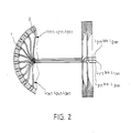
- Fig. 2 shows a cross section through the ball sensor head l partially cut.
- the parts corresponding to the parts in FIG. 1 are provided with the same reference numerals.
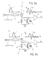
- the first light guides L111 to L 1nn are guided to the imaging optics 3 in order to image the front ends of these light guides on a photodiode 9 of the first detector stage 4.
- the photodiode 9 is connected in series with a damped resonant circuit which consists of a coil l0, a capacitor ll and a resistor l2.
- This parallel resonant circuit is also connected to an amplifier 13 at whose output a current flow I occurs.
- a laser pulse L is transmitted via the light guide bundle L 11 and L 1nn , which has a current profile shown in FIG. 3. It is assumed that the width of this laser pulse is 50 ns.
- the damped oscillation curve of the current of the damped oscillation circuit is also shown in FIG. 3a. In a subsequent stage, which is not shown in FIG. 3a, the first zero crossing I40 of the damped oscillation is determined and used as the start signal for a counting circuit shown in FIG. 4.
- Fig. 3b the second light guide bundle L211 to L 2nn is shown, which is guided to the imaging optics 5 of the detector stage (first stop stage) 6.
- the photodiode of this detector stage is labeled 14.
- the photodiode l4 is connected to a damped resonant circuit which consists of a resistor l5, a coil l6 and a capacitor l7.
- This resonant circuit has a resonant frequency which is equal to the resonant frequency of the resonant circuit shown in FIG. 3a. This means that the two resonant circuits are identical.
- a secondary amplifier is designated by l8. As can be seen from FIG.
- the laser pulse strikes the receiving optics 5 and consequently the photodiode 14.
- the damped vibration also starts with a corresponding delay.
- the first zero crossing of this damped oscillation is designated I60. This first zero crossing is delayed compared to the first zero crossing of the undelayed damped oscillation from FIG. 3a.
- the difference between the first zero crossings is the delay time, which is a measure of the azimuth angle of the incoming laser beam.
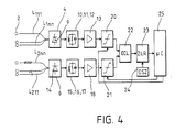
- the start channel is formed by the first light guide L111 to L 1nn in connection with the first detector stage 5, the resonant circuit l0, ll, l2 and the repeater l3 as well as a downstream threshold level 20 with a variable response level.
- the second channel or first stop channel is formed by the second light guide L211 to L 2nn , the second detector stage (first stop stage) with the photodiode l4, the resonant circuit l5, l6, l7, the repeater l8 and a downstream threshold level 2l with a variable response level.
- the outputs of the two threshold value stages 20 and 2l lead to an emitter-coupled logic circuit 22, in which an analog-digital conversion of the received signals is carried out. In addition, a zero point crossing determination is carried out in this circuit stage 22.
- This emitter-coupled logic circuit 22 is followed by a counter circuit 23, which is clocked by an oscillator 24.
- the counter circuit 23 is connected on the output side to a microcomputer 25 which has control outputs which lead to control inputs of the threshold value circuits 20 and 2l.
- the threshold value is automatically readjusted depending on the background lighting in order to avoid interference signals as far as possible.
Abstract
Eine Detektorvorrichtung weist zur richtungsabhängigen Erfassung von Laserstrahlung mindestens eine erste und zweite, jeweils einen opto-elektrischen Wandler aufweisenden Detektorstufe (4, 6), eine Vielzahl von Einzeloptiken (2), die insgesamt einen vorgegebenen Gesamtraumwinkel erfassen, wobei die Raumwinkel benachbarter Einzeloptiken einander überlappen und wobei die Einzeloptiken jeweils in Azimut-Ebenen angeordnet sind, einen ersten und zweiten Lichtleiter (L111, L211) für jede Einzeloptik, wobei die Lichtleiter (L111 bis L1nn; L211 bis L2nn) jeweils zur ersten und zweiten Detektorstufe (4, 6) führen, wobei sämtliche ersten zur ersten Detektorstufe führenden Lichtleiter gleiche Länge aufweisen, während die zu der zweiten Detektorstufe führenden zweiten Lichtleiter untereinander unterschiedlich lang sind, wobei ihre Längen in Azimut-Winkelrichtung gesehen zur Bildung von unterschiedlichen Laufzeiten abgestuft sind und eine Laüfzeitmeßvorrichtung, auf die mit der ersten und zweiten Detektorstufe in Verbindung steht, um Anfang und Ende der Laufzeitmessung ünd hiervon abhängig den Raumwinkel der einfallenden Laserstrahlüng festzustellen. Der opto-elektrische Wandler der ersten und zweiten Detektorstufe (4, 6) ist mit je einem gedämpften Schwingkreis (l0 bis l2, l5 bis l7) als Filterstufe verbunden, der so ausgelegt ist, daß dessen Resonanz-Periodendauer zumindest um den Faktor vier größer ist als die Dauer oder Anstiegszeit eines ankommenden Laserimpulses bzw. als der zeitliche Laufzeitabstand für benachbarte Einzeloptiken. Dem gedämpften Schwingkreis der ersten und zweiten Detektorstufe ist jeweils eine Nulldurchgangs-Detektorstufe (20, 2l) nachgeordnet, um jeweils beim ersten Nulldurchgang oder einem der folgenden Nülldurchgänge der betreffenden gedämpften Schwingungen ein Start- bzw. Stopsignal für die Laufzeitmeßschaltung zu erzeugen.For the direction-dependent detection of laser radiation, a detector device has at least a first and second detector stage (4, 6), each having an opto-electrical converter, and a multiplicity of individual optics (2), which collectively determine a predetermined total solid angle, the solid angles of adjacent individual optics overlapping one another and the individual optics are each arranged in azimuth planes, first and second light guides (L111, L211) for each individual optics, the light guides (L111 to L1nn; L211 to L2nn) leading to the first and second detector stages (4, 6), respectively , wherein all the first light guides leading to the first detector stage have the same length, while the second light guides leading to the second detector stage are of different lengths, their lengths in the azimuth-angular direction being graded to form different transit times, and a delay time measuring device to which the first and second D detector stage is connected in order to determine the start and end of the transit time measurement and, depending on this, the solid angle of the incident laser radiation. The opto-electrical converter of the first and second detector stages (4, 6) is connected to a damped resonant circuit (l0 to l2, l5 to l7) as a filter stage, which is designed so that its resonance period is at least four times larger is the duration or rise time of an incoming laser pulse or the time-of-flight interval for neighboring individual optics. The damped resonant circuit of the first and second detector stages is followed by a zero crossing detector stage (20, 2l) in order to generate a start or stop signal for the transit time measurement circuit at the first zero crossing or one of the following zero crossings of the damped vibrations in question.
Description
Die Erfindung betrifft eine Detektorvorrichtung zur richtungsabhängigen Erfassung von Laserstrahlung mit mindestens einer ersten und zweiten, jeweils einem opto-elektrischen Wandler aufweisenden Detektorstufe, mit einer Vielzahl von Einzeloptiken, die insgesamt einen vorgegebenen Gesamtraumwinkel erfassen, wobei die Raumwinkel benachbarter Einzeloptiken einander überlappen und wobei die Einzeloptiken jeweils in Azimut-Ebenen angeordnet sind, mit einem ersten und zweiten Lichtleiter für jede Einzeloptik, wobei die Lichtleiter jeweils zur ersten und zweiten Detektorstufe führen, wobei sämtliche ersten Lichtleiter gleiche Länge aufweisen und zur ersten Detektorstufe führen, während die zu der zweiten Detektorstüfe führenden zweiten Lichtleiter untereinander unterschiedlich lang sind und ihre Längen in Azimut-Winkelrichtung zur Bildung von unterschiedlichen Laufzeiten abgestuft sind und mit einer Laufzeitmeßvorrichtung, die mit der ersten und zweiten Detektorstufe in Verbindung steht, um Anfang und Ende der Laufzeitmessung und hiervon abhängig den Azimut-Winkel der einfallenden Laserstrahlung festzustellen. Unter Azimut-Ebene wird im folgenden eine horizontale Ebene verstanden, in der die Azimut-Winkel gemessen werden.The invention relates to a detector device for the direction-dependent detection of laser radiation with at least a first and second, each having an opto-electrical converter detector stage, with a plurality of individual optics, which collectively determine a predetermined total solid angle, the solid angles of adjacent individual optics overlapping one another and the individual optics are each arranged in azimuth planes, with a first and second light guide for each individual optical system, the light guides leading to the first and second detector stages, all of the first light guides having the same length and leading to the first detector stage, while the second leads to the second detector stage Light guides are of different lengths from one another and their lengths are graduated in the azimuth angular direction to form different transit times and with a transit time measuring device which is connected to the first and second detector stages by A Determine the beginning and end of the transit time measurement and, depending on this, the azimuth angle of the incident laser radiation. In the following, the azimuth plane is understood to mean a horizontal plane in which the azimuth angles are measured.
Laserstrahlung, welche im sichtbaren oder Infrarotbereich strahlt, wird vielfach und vielseitig auf militärischem Gebiet eingesetzt. Am häufigsten werden gepulste oder intensitätsmodulierte Laserstrahlungen zur Entfernungsbestimmung für Feuerleitsysteme, Beleuchtung eines Zieles für die Zielidentifizierung eines Flügkörpersensors und für die direkte Steuerung des Flugkörpers verwendet und zwar in Verbindung mit Laserleitstrahlen.Laser radiation, which radiates in the visible or infrared range, is used in many and varied ways in the military field. Most often, pulsed or intensity-modulated laser radiation is used to determine the distance for fire control systems, to illuminate a target for the target identification of a missile sensor and for direct control of the missile in connection with laser beacons.
Damit nun rechtzeitige Abwehrmaßnahmen für eine solche Angriffs-Laserbestrahlung ergriffen werden können, muß vorher die Art einer Bedrohung festgestellt werden. Daher ist es notwendig, am Ziel selbst die Laserstrahlung festzustellen und sie aus einer störenden Hintergrundsstrahlung zu identifizieren. Auch ist es notwendig, die charakteristischen Merkmale dieser Laserstrahlung, wie z.B. deren Wellenlänge und die Signatur hinsichtlich der Pulslänge und der Pulswiederholrate zu analysieren. Für gezielte Gegenmaßnahmen, welche entweder passiv als Standortwechsel-Täuschung falscher Ziele und Einneblung oder aktiv in Form von Zurückblenden oder direkter Bekämpfung sein kann, ist es besonders notwendig, die Einfallsrichtung der Laserstrahlung auf das Ziel genau zu messen.So that timely countermeasures for such attack laser radiation can now be taken, the type of threat must be determined beforehand. It is therefore necessary to determine the laser radiation yourself at the target and to identify it from a disturbing background radiation. It is also necessary to determine the characteristic features of this laser radiation, e.g. to analyze their wavelength and the signature with regard to the pulse length and the pulse repetition rate. For targeted countermeasures, which can either be passive as a change of location to deceive wrong targets and fogging or active in the form of flashbacks or direct combat, it is particularly necessary to measure the direction of incidence of the laser radiation precisely to the target.
Bei verschiedenartigen Zielen, wie z.B. Fahrzeugen, Schiffen, Hubschraubern, Flugzeugen und Satelliten bestehen unterschiedliche Anforderungen an die Weite des erfaßten Raumwinkels sowie an die Winkelauflösung eines Warnsensors in Azimut-Richtung und Elevations-Richtung. So wird beispielsweise für Fahrzeuge im Gelände, wie z.B. Panzer und Lastwagen, meist mit einer Bedrohung aus Winkelbereichen in der Nähe der horizontalen Ebene (z.B. von anderen Panzern oder tieffliegenden Hubschraübern), gerechnet. Der Erfassungsbereich liegt daher bei einem Winkelbereich von 360° in der Azimut-Ebene und bei einem Winkelbereich von ± 30° in der Elevations-Ebene. Unter Elevationsebene wird im folgenden jede zur Azimut-Ebene senkrechte Ebene verstanden, in der die Elevationswinkel gemessen werden.For different types of targets, such as vehicles, ships, helicopters, airplanes and satellites, there are different requirements for the width of the detected solid angle and for the angular resolution of a warning sensor in the azimuth direction and elevation direction. For example, for off-road vehicles such as tanks and trucks, a threat from angle areas close to the horizontal plane (e.g. from other tanks or low-lying helicopters) is usually expected. The detection range is therefore an angular range of 360 ° in the azimuth plane and an angular range of ± 30 ° in the elevation plane. In the following, the elevation plane is understood to mean any plane perpendicular to the azimuth plane in which the elevation angles are measured.
Da aufgrund der Unebenheit des Geländes Fahrzeuge ständig ihre Lage um die horizontale Achse ändern, ist eine genaue Winkelmessung einer Laserstrahlungsquelle in Elevations-Richtung in bezug auf das Koordinatensystem des Fahrzeuges von untergeordneter Bedeutung, während die Winkelmessungen in jeder Azimut-Ebene exakt sein müssen.Since vehicles constantly change their position around the horizontal axis due to the unevenness of the terrain, an accurate angle measurement of a laser radiation source in the elevation direction is of secondary importance with respect to the coordinate system of the vehicle, while the angle measurements must be exact in each azimuth plane.
Die Bewegungen von Fahrzeugen um die vertikale Achse sind sehr viel langsamer. Dies bedeutet, daß die Azimut-Messung ihre Gültigkeit über einen wesentlich längeren Zeitraum behält. Mit Hilfe zusätzlicher Mittel, wie z.B. Mittel zur visionellen Beobachtung der landschaftlichen Struktur kann die Laserstrahlungsquelle genau geortet werden. Damit nun aber die Erfassung der Laserstrahlungsquelle in jeder Bewegungslage des Fahrzeuges möglich ist, muß die volle Empfindlichkeit des Strahlungssensors über den gesamten geforderten Elevations-Bereich gewährleistet sein. Dies bedeutet, daß der Strahlungssensor den gesamten Azimut-Elevations-Bereich lückenlos umfassen muß.The movements of vehicles around the vertical axis are much slower. This means that the azimuth measurement remains valid for a much longer period of time. With the help of additional means, e.g. The laser radiation source can be precisely located by means of visionary observation of the landscape structure. So that the detection of the laser radiation source is possible in every movement position of the vehicle, the full sensitivity of the radiation sensor must be guaranteed over the entire required elevation range. This means that the radiation sensor must cover the entire azimuth elevation area without gaps.
Bei anderen Zielen, wie z.B. Hubschraubern, Flugzeugen und Satelliten ist aufgrund der größeren Beweglichkeit dieser Ziele in den verschiedenen Raumwinkelbereichen sowie aufgrund der verschiedenen moglichen Drehbewegungen die Situation abweichend von der zuvor beschriebenen. Hier ist sowohl eine genaue Winkelauflösung in Azimut-Richtung als auch Elevations-Richtung wichtig. Meistens ist der geforderte und gewünschte Raumwinkelbereich in Azimut-Richtung 360° und in Elevations-Richtung ± 90°.For other goals, such as Because of the greater mobility of these targets in the different solid angle ranges and because of the various possible rotary movements, helicopters, airplanes and satellites differ from the situation described above. Here, an exact angular resolution in the azimuth direction as well as the elevation direction is important. The required and desired solid angle range is usually 360 ° in the azimuth direction and ± 90 ° in the elevation direction.
Außer den unterschiedlichen Anforderungen für die Winkelerfassung von Laserwarnsensoren besteht darüberhinaus beim Anwender der Wunsch, möglichst unterschiedliche Laserstrahlungsquellen mit ein und demselben Gerät feststellen zu können.In addition to the different requirements for the angle detection of laser warning sensors, the user also wishes to be able to determine as different laser radiation sources as possible with one and the same device.
In Anbetracht der großen Anzahl von verschiedenen militärischen Laserstrahlungsquellen im Bereich von kurzwelligem sichtbarem Licht bis hin zur Strahlung im thermischen Infrarotgebiet dürfen die Strahlungsdetektoren hinsichtlich der spektralen Empfindlichkeit und Empfangsbereitschaft nicht durch Filter eingeengt werden, welche vor den Fotodetektoren angeordnet sind, wobei diese Filter an sich dazu dienen, um Störungen durch das Hintergrundslicht zu reduzieren. Solche Filter reduzieren automatisch die spektrale Empfindlichkeit solche opto-elektrischer Sensoren.In view of the large number of different military laser radiation sources in the range from short-wave visible light to radiation in the thermal infrared region, the radiation detectors must not be restricted in terms of spectral sensitivity and readiness for reception by filters which are arranged in front of the photodetectors, these filters themselves serve to reduce interference from the backlight. Such filters automatically reduce the spectral sensitivity of such opto-electrical sensors.
Im einzelen betragen die Hellenlängenbereiche für frequenzverschobene Excimer-Laser 0,4 µm bis 0,5 µm, für Rubin-Laser 0,69 µm, für Laser-Dioden 0,85 µm bis 0,95 µm, für Alexandrit-Laser 0,75 µm bis 0,85 µm, für Nd:YAG l,06 µm und l,32 µm, für Nd:YAG-Methan Raman Shifted l,52 µm, für Erbium l,65 µm, für Holmium 2,l2 µm, für Deuterium Fluorid 3,6 µm bis 4,0 µm, für CO₂-Laser 9,5 µm bis ll,5 µm. Zum anderen muß der Laserstrahlungssensor aufgrund der Beweglichkeit der Zielobjekte unter den unterschiedlichsten Beleuchtungsbedingungen einwandfrei und funktionstüchtig arbeiten. Auch muß gewährleistet sein, daß bei direkter Einstrahlung der Sonne in das Gesichtsfeld des Strahlungssensors die Fehlalarmrate niedrig bleibt. Auch muß ein solcher Laserstrahlungssensor unempfindlich sein gegen andere künstliche Beleuchtungsquellen, bei denen keine Laserstrahlung abgegeben wird, wie z.B. Stroboskope, Blitzlampen, Kanonenfeuer, Leuchtbomben, Leuchtblitze usw..Specifically, the wavelength ranges for frequency-shifted excimer lasers are 0.4 µm to 0.5 µm, for ruby lasers 0.69 µm, for laser diodes 0.85 µm to 0.95 µm, for alexandrite lasers 0.75 µm to 0.85 µm, for Nd: YAG 1.06 µm and 1.32 µm, for Nd: YAG-methane Raman Shifted 1. 52 µm, for erbium 1.65 µm, for holmium 2.12 µm, for deuterium Fluoride 3.6 µm to 4.0 µm, for CO₂ lasers 9.5 µm to 11.5 µm. On the other hand, due to the mobility of the target objects, the laser radiation sensor must work properly and functionally under the most varied lighting conditions. It must also be ensured that the false alarm rate remains low when the sun is shining directly into the field of view of the radiation sensor. Such a laser radiation sensor must also be insensitive to other artificial lighting sources in which no laser radiation is emitted, e.g. Stroboscopes, flashlights, cannon fire, light bombs, flashes, etc.
Auch muß durch die Detektorvorrichtung ein großer dynamischer Signalbereich erfaßt werden, um zu gewährleisten, daß die Detektorvorrichtung auch bei verschiedenen Wetterverhältnissen, bei unterschiedlichen Abständen zwischen dem Warnsensor und der Strahlungsquelle bei sich ändernder Pulsenergie des Lasers, bei sich änderndem Auftreffort der Laserstrahlung am Ziel und bei Turbulenzfluktuationen der Atmosphäre über den Strahlquerschnitt einwandfrei arbeitet. Außerdem müssen gleichzeitig Störungen der Winkelmessung durch sekundäre Reflexionen der Laserstrahlung in der Umgebung und am Ziel möglichst vermieden werden.A large dynamic signal range must also be detected by the detector device, in order to ensure that the detector device is in itself even in different weather conditions, with different distances between the warning sensor and the radiation source when the pulse energy of the laser changes changing impact of the laser radiation at the target and in the event of turbulence fluctuations in the atmosphere across the beam cross-section works perfectly. In addition, disturbances in the angle measurement caused by secondary reflections of the laser radiation in the surroundings and at the target must be avoided as far as possible.
Die eingangs erwähnte Detektorvorrichtung ist aus der DE-PS 33 23 828 sowie aus der DE-OS 35 25 5l8 bekannt. Die Richtung der einfallenden Laserstrahlung wird daher mit Hilfe einer Laufzeitmessung festgestellt und bestimmt, wobei die Laserstrahlung in Lichtleitfasern geführt wird. Hierzu sind zwei Lichtleiter hinter einer gemeinsamen Einzeloptik vorgesehen. In Abhängigkeit von der Größe des zu erfassenden Raumwinkels sind zahlreiche solcher Einzeloptiken vorgesehen. Jeweils benachbarte Einzeloptiken weisen überlappende Einzelraumwinkelbereiche auf. Sämtliche erste Lichtleiter der Einzeloptiken sind zu einem ersten Detektor geführt, welcher beim Eintreffen eines Laserimpulses oder Laserpulses eine Laufzeitmeßschaltung in Gang setzt. Sämtliche zweite Lichtleiter, die jeweils unterschiedliche Längen aufweisen, sind mit einem zweiten Detektor verbunden, durch den die in Gang gesetzte Zählschaltung gestoppt wird. Je nach festgestellter Strahlungsrichtung wird die Zähischaltung früher oder später stillgesetzt. Diese Lichtleiter dienen als Verzögerungsleitungen für die Laserstrahlung. Der Zeitunterschied zwischen dem Start und dem Stop der Zählschaltung ist ein Maß für den Winkel in der Azimut-Ebene. Da mehrere der Lichtleitpaare in Verbindung mit den Einzeloptiken zur Steuerung der Zeitmeßschaltung vorgesehen sind und dabei benachbarte Einzeloptiken sich hinsichtlich ihrer Raumwinkel überlappen, ist eine Rundumsicht und vollständige Raumwinkelerfassung gewährleistet. Da sämtliche ersten Lichtleiter gleich lang sind, tritt der jeweilige Startimpuls jeweils zur gleichen Zeit nach Eintreffen eines Laserimpulses auf.The detector device mentioned at the outset is known from DE-PS 33 23 828 and from DE-OS 35 25 5l8. The direction of the incident laser radiation is therefore determined and determined with the aid of a transit time measurement, the laser radiation being guided in optical fibers. For this purpose, two light guides are provided behind a common individual optics. Depending on the size of the solid angle to be detected, numerous such individual optics are provided. Adjacent individual optics have overlapping individual solid angle ranges. All the first light guides of the individual optics are led to a first detector, which starts a transit time measurement circuit when a laser pulse or laser pulse arrives. All of the second light guides, each of different lengths, are connected to a second detector, by means of which the counting circuit started is stopped. Depending on the determined radiation direction, the counting circuit is stopped sooner or later. These light guides serve as delay lines for the laser radiation. The time difference between the start and the stop of the counter circuit is a measure of the angle in the azimuth plane. Since several of the light guide pairs are provided in connection with the individual optics for controlling the time measurement circuit and adjacent individual optics overlap in terms of their solid angle, an all-round view and complete solid angle detection is ensured. Since all of the first light guides are of the same length, the respective start pulse occurs at the same time after the arrival of a laser pulse.
In Wirklichkeit ist es so, daß nicht nur durch eine Einzeloptik Laserstrahlung zum zugeordneten Paar der Lichtleiter gelangt, sondern auch über die benachbarten Einzeloptiken zu den dortigen Lichtleitpaaren. Das bedeutet, daß die zweite Detektorstufe nicht nur einen Hauptimpuls über die Einzeloptik und den zugeordneten zweiten Lichtleiter erhält über den die stärkste Strahlung einfällt, sondern zusätzlich auch schwächere Lasersignale über die benachbarten Einzeloptiken und zweiten Lichtleiter detektiert werden. Aufgrund dessen erhält man neben dem Hauptlaserpuls einen voreilenden schwächeren und einen nacheilenden schwächeren Laserpuls. Um nun den genauen azimutalen Raumwinkel der einfallenden Strahlung festzustellen wird eine Interpolationsoperation durchgeführt, um den zeitlichen Schwerpunkt dieser drei Empfangsimpulse zu ermitteln. Hierfür sind entsprechende Rechenoperationen notwendig wie dies in der DE-OS 35 25 5l8 näher beschrieben ist.In reality, it is the case that laser radiation reaches the associated pair of light guides not only through a single optical system, but also through the neighboring individual optical systems to the light guide pairs there. This means that the second detector stage not only receives a main pulse via the individual optics and the assigned second light guide through which the strongest radiation is incident, but also weaker laser signals are also detected via the adjacent individual optics and second light guides. Because of this, in addition to the main laser pulse, a leading weaker and a lagging weaker laser pulse are obtained. In order to determine the exact azimuthal solid angle of the incident radiation, an interpolation operation is carried out in order to determine the temporal focus of these three received pulses. Corresponding arithmetic operations are necessary for this, as is described in more detail in DE-OS 35 25 518.
Der Erfindung liegt nun die Aufgabe zugrunde, eine Detektorvorrichtung der eingangs genannten Art zu schaffen, die in einfacher Weise eine genaue Winkelbestimmüng aüfgrund der Laufzeitmessung ermöglicht, ohne daß hierbei eine zeitliche und aufwendige Schwerpunktsschaltung notwendig ist. Darüberhinaus soll der Einfluß von Störsignalen möglichst gering gehalten werden.The invention is based on the object of providing a detector device of the type mentioned at the outset which in a simple manner enables an exact angle determination on the basis of the transit time measurement, without the need for a time-consuming and complex shifting of the center of gravity. In addition, the influence of interference signals should be kept as low as possible.
Gelöst wird diese Aufgabe erfindungsgemäß dadurch, daß der opto-elektrische Handler der ersten und zweiten Detektorstufe mit je einem gedämpften Schwingkreis verbunden ist, und daß die Dauer der Anstiegsphase einer Resonanz-Schwingung bis zum Erreichen der Amplitude größer oder gleich der typischen Dauer bzw. Anstiegszeit eines mindestens auf einer Einzeloptik ankommenden Laserimpulses ist und daß dem gedämpften Schwingkreis der ersten und zweiten Detektorstufe jeweils eine Nulldurchgangs-Detektorstufe nachgeordnet ist um jeweils beim ersten Nulldurchgang oder einem der folgenden Nulldurchgänge der betreffenden gedämpften Schwingungen ein Start- bzw. Stopsignal für die Laufzeitmeßschaltung zu erzeugen.This object is achieved according to the invention in that the opto-electrical handler of the first and second detector stages is connected to a damped resonant circuit, and that the duration of the rise phase of a resonance oscillation until the amplitude is reached is greater than or equal to the typical duration or rise time of a laser pulse arriving at least on a single optical unit and that the damped resonant circuit of the first and second detector stages in each case a zero-crossing detector stage is arranged in order to generate a start or stop signal for the transit time measuring circuit at the first zero crossing or one of the following zero crossings of the damped vibrations in question.
Auf diese Weise ist eine sehr einfache elektronische Detektorvorrichtung geschaffen worden, die einen eindeutigen Zeitreferenzpunkt für die Laufzeitmessung liefert nd zwar sowohl für den ankommenden Laserimpuls als auch für den zeitverzögerten Laserimpuls für die Azimut-Winkelbestimmung. Auch wenn Laserstrahlung auf zwei oder drei benachbarte Einzeloptiken und Lichtleiter einfällt, erfolgt eine sehr genaue Azimut-Winkelbestimmung durch eine zeitliche Schwerpunktsbildung der gedämpften Schwingung des Schwingkreises. Aufgrund der Tatsache, daß die Resonanz-Periodendauer bzw. Resonanzfrequenz entsprechend gewählt ist, nämlich etwa um den Faktor vier größer als die Dauer- oder Anstiegszeit des ankommmenden Laserimpulses, wird die Phasenlage des harmonischen Gesamtsignals mit dem zeitlichen Schwerpunkt des Laserimpulssignals streng korreliert. Treffen beispielsweise zwei Impulse mit einem Abstand kleiner als l/4 der Periodendauer der harmonischen gedämpften Schwingung auf den Detektor ein, dann erfolgt automatisch eine Superposition derart, daß die resultierende harmonische Schwingung mit dem gemeinsamen Schwerpunkt korreliert ist. Dies bedeutet, daß durch Messung des ersten oder zweiten oder auch folgenden Nulldurchganges der gedämpften harmonischen Schwingung eine eindeutige Zeitreferenz für die Messüng des Laufzeitunterschiedes zwischen dem unverzögerten und dem verzögerten Laserimpuls geschaffen ist. Die Interpolation zwischen zwei benachbarten Impulsen erfolgt automatisch.In this way, a very simple electronic detector device has been created which provides a clear time reference point for the transit time measurement, both for the incoming laser pulse and for the time-delayed laser pulse for the azimuth angle determination. Even if laser radiation is incident on two or three adjacent individual optics and light guides, the azimuth angle is determined very precisely by establishing the center of gravity of the damped oscillation of the resonant circuit over time. Due to the fact that the resonance period or resonance frequency is chosen accordingly, namely approximately four times greater than the duration or rise time of the incoming laser pulse, the phase position of the overall harmonic signal is strictly correlated with the temporal focus of the laser pulse signal. If, for example, two pulses arrive at the detector with a distance of less than 1/4 of the period of the harmonic damped oscillation, then a superposition takes place automatically in such a way that the resulting harmonic oscillation is correlated with the common center of gravity. This means that by measuring the first or second or subsequent zero crossing of the damped harmonic oscillation, a clear time reference is created for measuring the difference in transit time between the undelayed and the delayed laser pulse. The interpolation between two neighboring pulses takes place automatically.
Ein weiterer Vorteil der Erfindung ist darin zu sehen, daß die Arbeitsweise der Detektorvorrichtung unabhängig ist von der Impulsamplitude, da im linearen Bereich des opto-elektrischen Wandlers (Photodiode) gearbeitet wird. Es treten keine Verfälschüngen der Phase durch eventuelle nichtlineare Verstärkungen der Signale auf. Es kann ein sehr weiter dynamischer Signalbereich von z.B.
> l20 dB erfaßt werden.Another advantage of the invention can be seen in the fact that the mode of operation of the detector device is independent of the pulse amplitude, since the linear range of the opto-electrical converter (photodiode) is used. There are no falsifications of the phase due to possible non-linear amplifications of the signals. A very wide dynamic signal range of e.g.
> 120 dB can be recorded.
Der gedämpfte Schwingkreis mit definierter Resonanzfrequenz wirkt wie ein selektives Filter mit einer definierten Bandbreite. Signale im Bereich der Resonanzfrequenz werden mit geringer Dämpfung weitergeleitet, während Frequenzanteile der Signale die außerhalb der Bandbreite liegen, sehr stark gedämpft werden.The damped resonant circuit with a defined resonance frequency acts like a selective filter with a defined bandwidth. Signals in the range of the resonance frequency are passed on with low attenuation, while frequency components of the signals that lie outside the bandwidth are attenuated very strongly.
Insbesondere bei militärischen Laseranwendungen werden Laserimpulse mit einer Breite zwischen l0 ns bis 200 ns verwendet oder aber lange Impulse mit Impulslängen im Bereich von Mikrosekunden bis Sekunden. Solche langen Impulse weisen jedoch in Regel sehr kurze Anstiegszeiten im Bereich von 50 ns bis 200 ns auf.In military laser applications in particular, laser pulses with a width between 10 ns to 200 ns are used, or long pulses with pulse lengths in the range from microseconds to seconds. However, such long pulses generally have very short rise times in the range from 50 ns to 200 ns.
Gegenüber anderen schnellen Lichtvorgängen mit Anstiegszeiten größer als einige Mikrosekunden besitzen Laserimpulse Schwingungsfrequenzanteile von merklich höherer Frequenz. Dies bedeutet, daß mit einem selektiven Schwingungsfilter das auf eine feste bzw. mittlere Grundfrequenz des Laserimpulses abgestimmt ist, diese Grundfrequenz einschließlich der benachbarten, innerhalb der Bandbreite liegenden Frequenzanteile von anderen Lichtvorgängen effektiv getrennt werden kann.Compared to other fast light processes with rise times greater than a few microseconds, laser pulses have oscillation frequency components of a noticeably higher frequency. This means that with a selective vibration filter that is tuned to a fixed or average fundamental frequency of the laser pulse, this fundamental frequency including the adjacent frequency components within the bandwidth can be effectively separated from other light processes.
Gemäß weiterer Ausgestaltung bewirken Laserimpulsanteile mit einer Breite von T eine Resonanzwirkung am gedämpften Schwingkreis dann, wenn dessen Resonanzfrequenz umgekehrt proportional ist dem achtfachen Wert der Laserimpulsbreite. Ausgehend von der oben erwähnten Breite der Laserimpulse ergibt sich eine optimale Schwingungsfrequenz im Bereich von einigen MHz.According to a further embodiment, laser pulse components with a width of T bring about a resonance effect on the damped resonant circuit when its resonance frequency is inversely proportional to the eight times the value of the laser pulse width. Based on the width of the laser pulses mentioned above, an optimal oscillation frequency in the range of a few MHz results.
Gemäß weiterer Ausgestaltung ist eine Fehlsignalschaltung vorgesehen, die eine Zeitfensterstufe aufweist, die durch die erste und zweite Detektorstufe beeinflußbar ist und ein Sperrsignal für die Laufzeitmeßschaltung oder eine nachgeordnete Auswerteschaltung erzeugt, wenn die Zeit zwischen dem Startsignal und dem Stopsignal größer ist als die maximale Laufzeitdifferenz zwischen dem längsten zweiten Lichtleiter und dem ersten Lichtleiter. Hieraus ergibt sich der Vorteil, daß eine Zeitmessung nur dann initiiert und ausgewertet wird, wenn das Startsignal und das Stopsignal im Zeitfenster l,egen. Gemäß weiterer Ausbildung ist dem gedämpften Schwingkreis der ersten und zweiten Detektorstufe jeweils eine Schwellwertstufe mit variabler Triggerschwelle nachgeordnet, die dürch eine Störsignaldetektorschaltung veränderbar ist, in der die Häufigkeit der Störsignalspitzen z. B. verursacht von Rauschspitzen, insbesondere der Hintergrundbeleuchtung festgestellt werden und durch die die Triggerschwelle entsprechend nachgeregelt wird. Auf diese Weise wird die Wahrscheinlichkeit eines Fehlalarmes entsprechend stark reduziert. Da die Wahrscheinlichkeit der Feststellung von Signalen am opto-elektrischen Wandler für schwache Laserimpulse von der Höhe der eingestellten Triggerschwelle abhängt, ergibt sich der Vorteil, daß z.B. bei schwacher Tagesbeleuchtung die Empfindlichkeit der Vorrichtung wesentlich höher ist als bei starker Sonnenbeleuchtung und zwar im sichtbaren und im Infrarot-Empfindlichkeitsbereich des opto-elektrischen Wandlers.According to a further embodiment, a false signal circuit is provided which has a time window stage which can be influenced by the first and second detector stages and which generates a blocking signal for the transit time measuring circuit or a downstream evaluation circuit if the time between the start signal and the stop signal is greater than the maximum transit time difference between the longest second light guide and the first light guide. This has the advantage that a time measurement is only initiated and evaluated if the start signal and the stop signal in the
In vorteilhafter Weise sind die beiden Nulldurchgangsdetektorstufen bzw. Schwellwertstufen mit einer digitalen Logikschaltung verbunden. Die Laufzeitmeßschaltung ist zweckmäßigerweise eine durch einen Oszillator getaktete Zählschaltung.The two zero crossing detector stages or threshold value stages are advantageously connected to a digital logic circuit. The transit time measuring circuit is expediently a counting circuit clocked by an oscillator.
Gemäß einer besonders vorteilhaften Ausgestaltung ist jeder der Einzeloptiken zusätzlich ein dritter Lichtleiter zugeordnet, wobei die dritten Lichtleiter von jeweils in der gleichen zur Azimu-Ebene senkrechten Elevations-Ebene befindlichen Einzeloptiken untereinander unterschiedlich lang sind und in Elevations-Winkelrichtung gesehen abgestuft sind und zu einer dritten Detektorstufe führen, die ebenfalls mit einem gedämpften Schwingkreis verbunden ist. Auf diese Weise ergibt sich die vorteilhafte Möglichkeit, nicht nur in der Azimut-Ebene eine genaue Winkelbestimmung der einfallenden Laserstrahlüng dürchzuführen, sondern auch in Elevations-Richtung.According to a particularly advantageous embodiment, each of the individual optics is additionally assigned a third light guide, the third light guides of individual optics located in the same elevation plane perpendicular to the azimu plane are of different lengths from one another and are stepped in the elevation angle direction and lead to a third detector stage, which is also connected to a damped resonant circuit. In this way, there is the advantageous possibility of not only performing an accurate angle determination of the incident laser beam in the azimuth plane, but also in the direction of elevation.
Gemäß weiterer Ausgestaltung weisen sämtliche dritten Lichtleiter in der Azimuts-Ebene jeweils gleiche Länge auf. Das bedeutet, daß unabhängig von der Azimut-Winkelposition der einfallenden Laserstrahlung die in Elevation-Richtung gesehene Empfindlichkeit gleich groß ist.According to a further embodiment, all third light guides in the azimuth plane each have the same length. This means that regardless of the azimuth angular position of the incident laser radiation, the sensitivity seen in the elevation direction is the same.
Gemäß weiterer Ausbildung sind sämtliche zweiten Lichtleiter einer Elevations-Ebene jeweils gleich lang ausgebildet. Das bedeutet, daß die Empfindlichkeit in Azimut-Winkelrichtung unabhängig von der ermittelten Elevations-Richtung der Laserstrahlung ist.According to a further embodiment, all second light guides of an elevation level are each of the same length. This means that the sensitivity in the azimuth angle direction is independent of the determined elevation direction of the laser radiation.
Somit erhält man vorteilhafter Weise die gleichzeitige und gleich große Winkelauflösung in Azimut-Richtung sowie in Elevations-Richtung. Dies ist besonders von Bedeutung bei der Detektierung von fliegenden Zielen. Auf diese Weise entsteht zu den Lichtleiterbündelreihen in Elevations-Richtung eine gleichartige Lichtleiterbündelreihe in Azimut-Richtung. Jeder der beiden Lichtbündelreihen ist eine Detektorstufe zur Erzeugung eines Stopsignales zugeordnet. Für die Laufzeitmeßschaltung ist zur Messung der Laufzeitdifferenz sowohl in Elevations- als auch in Azimut-Richtüng eine gemeinsame Detektorstufe zur Schaffung des Startsignales vorgesehen.The simultaneous and equally large angular resolution in the azimuth direction and in the elevation direction is thus advantageously obtained. This is of particular importance in the detection of flying targets. In this way, a similar row of optical fibers is created in the azimuth direction to the rows of optical fibers in the elevation direction. A detector stage for generating a stop signal is assigned to each of the two rows of light beams. For the transit time measurement circuit, a common detector stage is provided for measuring the transit time difference in both elevation and azimuth directions to create the start signal.
Im folgenden wird die Erfindung anhand eines in den Fig. l bis 4 dargestellten Ausführungsbeispieles beschrieben. Es zeigen
- Fig. l eine schematische Darstellung der Detektorvorrichtung mit in Azimut-Ebenen und in Elevations-Ebenen angeordneten Einzeloptiken mit Lichtleitern,
- Fig. 2 einen Querschnitt durch einen Sensorkopf der Detektorvorrichtung,
- Fig. 3a und 3b die Lasersignalaufbereitung in der zugehörigen Detektorstufe und
- Fig. 4 eine schematische Schaltungsanordnung zur Signalverarbeitung und Auswertung.
- 1 shows a schematic illustration of the detector device with individual optics with light guides arranged in azimuth planes and in elevation planes,
- 2 shows a cross section through a sensor head of the detector device,
- 3a and 3b, the laser signal processing in the associated detector stage and
- 4 shows a schematic circuit arrangement for signal processing and evaluation.
Gemäß Fig. l ist mit l der Sensorkopf einer Detektorvorrichtung bezeichnet. Dieser Sensorkopf ist ein Kugelgehäüse, welches eine Vielzahl von Öffnungen in Azimut-Richtung und in Elevations-Richtung aufweist. In diesen Gehäuseöffnungen befinden sich Einzeloptiken die in Fig. l stellvertretend für alle Optiken mit 2 bezeichnet sind. Die Einzeloptiken bilden in den jeweiligen Azimut-Ebenen und in den Elevations-Ebenen Gruppen für die nachfolgende Auswertung. Hinter den Einzeloptiken befinden sich jeweils drei Lichtleiter. Das Ende des jeweiligen Lichtleiters ist in der Brennebene bzw. Abbildungsebene jeder Einzeloptik 2 angeordnet. Der erste Lichtleiter der ersten Einzeloptik der obersten Azimut-Ebene ist mit L₁₁₁ bezeichnet, während der um l80° versetzte erste Lichtleiter dieser Ebene mit L11n bezeichnet ist. Der erste Lichtleiter der ersten Einzeloptik der darunter befindlichen Azimut-Ebene ist L₁₂₁ bezeichnet usw.. Der erste Lichtleiter der ersten Einzeloptik der untersten Azimut-Ebene ist mit L1n1 bezeichnet, während der um l80° versetzte Lichtleiter mit L1nn bezeichnet ist.According to FIG. 1, the sensor head of a detector device is designated by 1. This sensor head is a spherical housing which has a large number of openings in the azimuth direction and in the elevation direction. In these housing openings there are individual optics, which are designated as 2 in FIG. 1 for all optics. The individual optics form groups for the subsequent evaluation in the respective azimuth levels and in the elevation levels. There are three light guides behind the individual optics. The end of the respective light guide is arranged in the focal plane or imaging plane of each
Alle diese ersten Lichtleiter L₁₁₁ bis L1nn weisen gleiche Länge auf und sind in einem Bündel zu einer Optik 3 geführt, die zur Abbildung des stirnseitigen Endes auf eine Detektoreinrichtung 4 dient. Diese Detektoreinrichtung oder Stufe 4 wird auch als Startstufe bezeichnet.All these first light guides L₁₁₁ to L 1nn have the same length and are guided in a bundle to an
Der zweite Lichtleiter der ersten Einzeloptik der obersten Azimut-Ebene ist mit L211 bezeichnet, während der um l80° versetzte Lichtleiter mit L21n bezeichnet ist. Der zweite Lichtleiter der ersten Einzeloptik der untersten Azimut-Ebene ist mit L2n1 bezeichnet, während der um l80° versetzte Lichtleiter die Bezeichnung L2nn trägt. Die zweiten in einer gemeinsamen Elevations-Ebene befindlichen Lichtleiter L₂₁₁ bis L2n1 sind als Lichtleiterbündel zusammengeführt und zu einer zweiten Empfangsoptik 5 geführt, welche die stirnseitigen Enden dieser Lichtleiter aüf einer zweiten Detektorstufe abbildet. Diese zweiten Lichtleiter L₂₁₁ bis L2n1 der ersten Elevations-Ebene weisen die gleiche Länge auf. Hie aus der Fig. l ersichtlich ist, befinden sich diese ersten Einzeloptiken senkrecht zu den Azimut Ebenen.The second light guide of the first individual optics of the top azimuth plane is designated L 211 , while the light guide offset by 180 ° is designated L 21n . The second light guide of the first individual optics of the lowest azimuth plane is designated L 2n1 , while the light guide offset by 180 ° bears the designation L 2nn . The second light guide L₂₁₁ to L 2n1 located in a common elevation plane are brought together as a light guide bundle and guided to a
Die einzelnen zweiten Lichtleiter der Einzeloptiken, die um l80° versetzt sind gegenüber den zuvor erwähnten ersten Einzeloptiken, in einer gemeinsamen Elevations-Ebene liegen, und die mit L21n bis L2nn bezeichnet sind, sind als Bündel zur gleichen Empfangsoptik 5 geführt. Sie weisen untereinander gleiche Länge auf. Jedoch sind diese Lichtleiter länger ausgebildet als die zuvor erwähnten Lichtleiter der ersten Einzeloptiken. Gleiches gilt für die einzelnen zweiten Lichtleiter derjenigen Einzeloptiken die jeweils in einer gemeinsamen Elevations-Ebene liegen und welche einen dazwischen liegenden Azimut-Winkel bezogen auf die ersten Einzeloptiken aufweist.The individual second light guides of the individual optics, which are offset by 180.degree. From the previously mentioned first individual optics , lie in a common elevation plane and which are denoted by L 21n to L 2nn are guided as a bundle to the
Das bedeutet, daß in Abhängigkeit vom jeweiligen Azimut-Winkel in jeder der Azimut-Ebenen eine gleich große Empfindlichkeit und Auflösung eines eintreffenden Laserimpulses möglich ist. Die mit 6 bezeichnete Detektorstufe wird auch als erste Stopstufe bezeichnet. Die abgestuften Längenunterschiede zwischen den Lichtleitern von benachbarten Elevations-Ebenen sind gleich groß. Dies bedeutet, daß der gemessene Längenunterschied im bezug auf die ersten Lichtleiter ein Maß für den Azimut-Winkel ist unter dem ein ankommender Laserimpuls auf den Kugelkopf der Detektorvorrichtung auftrifft.This means that, depending on the respective azimuth angle, an equally large sensitivity and resolution of an incoming laser pulse is possible in each of the azimuth planes. The designated 6 Detector stage is also referred to as the first stop stage. The graded differences in length between the light guides of neighboring elevation levels are the same size. This means that the measured difference in length with respect to the first light guide is a measure of the azimuth angle at which an incoming laser pulse strikes the spherical head of the detector device.
Der dritte Lichtleiter der ersten Einzeloptik der obersten Azimut-Ebene ist mit L₃₁₁ bezeichnet, während der um l80° versetzte dritte Lichtleiter der gleichen Ebene mit L31n bezeichnet ist. Sämtliche Lichtleiter L₃₁₁ bis L31n sind als Bündel zusammengeführt und zu einer Empfangsoptik 7 geführt, die das stirnseitige Bündelende auf eine Detektorstufe 8 abbildet, die auch als zweite Stopstufe bezeichnet ist. Die vorgenannten Lichtleiter L₃₁₁ bis L31n weisen gleiche Länge auf.The third light guide of the first single optics of the top azimuth level is designated L₃₁₁, while the third light guide offset by l80 ° of the same level is designated L 31n . All light guides L₃₁₁ to L 31n are brought together as a bundle and led to a receiving
Der dritte Lichtleiter der ersten Einzeloptik der untersten Azimut-Ebene ist mit L3n1 bezeichnet. Der um l80° versetzte Lichtleiter der gleichen Ebene weist das Bezugszeichen L3nn auf. Diese Lichtleiter L3n1 bis L3nn sind als Bündel zusammengefaßt und führen zur vorgenannten Empfangs-oder Abbildungsoptik 7, so daß auch deren stirnseitige Enden auf der dritten Detektorstufe 8 (zweite Stopstufe) abgebildet werden. Diese Lichtleiter L3n1 bis L3nn weisen untereinander gleiche Länge auf. Jedoch ist die Länge dieses Lichtleiterbündels unterschiedlich gegenüber der Länge der Lichtleiter der obersten Azimut-Ebene. Es ist auch denkbar, daB die Längenabstufung der einzelnen Lichtleiter der verschiedenen Azimut-Ebenen in anderer Weise erfolgt. So ist es beispielsweise denkbar, da8 die Äquator-Ebene des Kugelkopfes als Ursprungs-Azimut-Ebene betrachtet wird und daß die entsprechenden dritten Lichtleiter dieser Ebene eine erste Länge aufweisen, während die Längen der Lichtleitergruppen der darüber und darunter befindlichen Azimut-Ebenen bei Symmetrie jeweils die gleiche Länge aufweisen.The third light guide of the first individual optics of the lowest azimuth plane is designated L 3n1 . The light guide of the same plane, offset by 180 °, has the reference symbol L 3nn . These light guides L 3n1 to L 3nn are combined as a bundle and lead to the aforementioned receiving or
Die Abstufung ist entsprechend gewählt.The gradation is chosen accordingly.
Fig. 2 zeigt einen Querschnitt durch den Kugelsensorkopf l teilweise geschnitten. Die den Teilen von Fig. l entsprechenden Teile sind mit gleichen Bezugszeichen versehen.Fig. 2 shows a cross section through the ball sensor head l partially cut. The parts corresponding to the parts in FIG. 1 are provided with the same reference numerals.
In Fig. 3a sind die ersten Lichtleiter L₁₁₁ bis L1nn zur Abbildungsoptik 3 geführt um die stirnseitigen Enden dieser Lichtleiter auf einer Photodiode 9 der ersten Detektorstufe 4 abzubilden. Die Photodiode 9 ist mit einem gedämpften Schwingkreis in Reihe geschaltet der aus einer Spule l0, einem Kondensator ll und einem Widerstand l2 besteht. Dieser parallele Schwingkreis ist außerdem mit einem Verstärker l3 verbunden an dessen Ausgang ein Stromfluß I auftritt. Über das Lichtleiterbündel L₁₁₁ bis L1nn wird ein Laserimpuls L übertragen, der einen in der Fig. 3 gezeigten zeitlichen Stromverlauf aufweist. Es sei angenommen, daß die Breite dieses Laserimpulses 50 ns beträgt. Die Periodendauer des gedämpften Schwingkreises ist so gewählt, daß sie den vierfachen Wert der impulsdauer T = 50 ns aufweist. Dies bedeutet, daß die Resonanzfrequenz für den gedämpften Schwingkreis 5 MHz beträgt. Der gedämpfte Schwingungsverlauf des Stroms des gedämpften Schwingungskreises ist ebenfalls in Fig. 3a gezeigt. In einer Nachfolgestufe, die in Fig. 3a nicht gezeigt ist, wird der erste Nulldurchgang I₄₀ der gedämpften Schwingung festgestellt und als Startsignal für eine in Fig. 4 gezeigte Zählschaltung verwendet.In Fig. 3a, the first light guides L₁₁₁ to L 1nn are guided to the
In Fig. 3b ist das zweite Lichtleiterbündel L₂₁₁ bis L2nn gezeigt, das zur Abbildungsoptik 5 der Detektorstufe (ersten Stopstufe) 6 geführt ist. Die Photodiode dieser Detektorstufe ist mit l4 bezeichnet. Die Photodiode l4 ist mit einem gedämpften Schwingkreis verbunden, der aus einem Widerstand l5, einer Spule l6 und einem Kondensator l7 besteht. Dieser Schwingkreis weist eine Resonanzfrequenz auf, die gleich der Resonanzfrequenz des in Fig. 3a gezeigten Schwingkreises ist. Das bedeutet, daß die beiden Schwingkreise identisch ausgebildet sind. Mit l8 ist ein Folgeverstärker bezeichnet. Wie aus Fig. 3b ersichtlich ist, trifft aufgrund der längeren Ausbildung der Lichtleiter der Laserimpuls verzögert auf die Empfangsoptik 5 und demzufolge auf die Photodiode l4 auf. Entsprechend verzögert setzt auch die gedämpfte Schwingung ein. Der erste Nulldurchgang dieser gedämpften Schwingung ist mit I₆₀ bezeichnet. Dieser erste Nulldürchgang ist verzögert gegenüber dem ersten Nulldurchgang der unverzögerten gedämpften Schwingung von Fig. 3a. Die Differenz beider ersten Nulldurchgänge ist die Verzögerungszeit, welche ein Maß für den Azimut-Winkel des eintreffenden Laserstrahls ist.In Fig. 3b, the second light guide bundle L₂₁₁ to L 2nn is shown, which is guided to the
In Fig. 4 sind die den Teilen der vorhergehenden Figuren entsprechenden Teile mit gleichen Bezugszeichen versehen. Der Startkanal wird gebildet durch die ersten Lichtleiter L₁₁₁ bis L1nn in Verbindung mit der ersten Detektorstufe 5, dem Schwingkreis l0, ll, l2 und dem Folgeverstärker l3 sowie einer nachgeschalteten Schwellwertstufe 20 mit veränderbarem Ansprechpegel.In Fig. 4, the parts corresponding to the parts of the previous figures are given the same reference numerals. The start channel is formed by the first light guide L₁₁₁ to L 1nn in connection with the
Der zweite Kanal oder auch erste Stopkanal wird gebildet durch die zweiten Lichtleiter L₂₁₁ bis L2nn, der zweiten Detektorstufe (erste Stopstufe) mit der Photodiode l4, dem Schwingkreis l5, l6, l7, dem Folgeverstärker l8 und einer nachgeordneten Schwellwertstufe 2l mit veränderbarem Ansprechpegel. Die Ausgänge der beiden Schwellwertstufen 20 und 2l sind zu einer Emitter gekoppelten Logikschaltung 22 geführt, in der eine Analogdigitalwandlung der empfangenen Signale durchgeführt wird. Außerdem wird in dieser Schaltungsstufe 22 eine Nullpunktsdurchgangsermittlung durchgeführt. Dieser Emitter gekoppelten Logikschaltung 22 ist eine Zählschaltung 23 nachgeordnet, die durch einen Oszillator 24 getaktet wird. Die Zählschaltung 23 ist ausgangsseitig mit einem Mikrocomputer 25 verbunden, der Steuerausgänge aufweist, die zu Steuereingängen der Schwellwertschaltungen 20 und 2l führen. Mit Hilfe des Mikrocomputers 25 wird in Abhängigkeit von der Hintergrundbeleuchtung der Schwellwert automatisch nachgeregelt um Störsignale soweit als möglich zu vermeiden.The second channel or first stop channel is formed by the second light guide L₂₁₁ to L 2nn , the second detector stage (first stop stage) with the photodiode l4, the resonant circuit l5, l6, l7, the repeater l8 and a downstream threshold level 2l with a variable response level. The outputs of the two threshold value stages 20 and 2l lead to an emitter-coupled
Claims (12)
Priority Applications (4)
| Application Number | Priority Date | Filing Date | Title |
|---|---|---|---|
| DE8787104470T DE3764362D1 (en) | 1987-03-26 | 1987-03-26 | DETECTOR DEVICE. |
| EP87104470A EP0283538B1 (en) | 1987-03-26 | 1987-03-26 | Detector apparatus |
| ES87104470T ES2016816B3 (en) | 1987-03-26 | 1987-03-26 | DETECTION DEVICE |
| US07/165,639 US4825063A (en) | 1987-03-26 | 1988-03-08 | Radiation position detection using time-indicative variable-length fiber array |
Applications Claiming Priority (1)
| Application Number | Priority Date | Filing Date | Title |
|---|---|---|---|
| EP87104470A EP0283538B1 (en) | 1987-03-26 | 1987-03-26 | Detector apparatus |
Publications (2)
| Publication Number | Publication Date |
|---|---|
| EP0283538A1 true EP0283538A1 (en) | 1988-09-28 |
| EP0283538B1 EP0283538B1 (en) | 1990-08-16 |
Family
ID=8196870
Family Applications (1)
| Application Number | Title | Priority Date | Filing Date |
|---|---|---|---|
| EP87104470A Expired - Lifetime EP0283538B1 (en) | 1987-03-26 | 1987-03-26 | Detector apparatus |
Country Status (4)
| Country | Link |
|---|---|
| US (1) | US4825063A (en) |
| EP (1) | EP0283538B1 (en) |
| DE (1) | DE3764362D1 (en) |
| ES (1) | ES2016816B3 (en) |
Cited By (5)
| Publication number | Priority date | Publication date | Assignee | Title |
|---|---|---|---|---|
| DE3818229C1 (en) * | 1988-05-28 | 1989-12-07 | Messerschmitt-Boelkow-Blohm Gmbh, 8012 Ottobrunn, De | |
| WO1998022833A1 (en) * | 1996-11-19 | 1998-05-28 | Tracor Aerospace, Inc. | Fiber optic guidance system for laser guided missiles |
| DE102007024051A1 (en) | 2007-05-22 | 2008-11-27 | Eads Deutschland Gmbh | Device and method for the detection and localization of laser radiation sources |
| DE102012022258A1 (en) | 2012-11-14 | 2014-05-15 | Eads Deutschland Gmbh | Sensor for detection and localization of laser radiation sources |
| EP3663798A1 (en) * | 2018-12-07 | 2020-06-10 | Sick Ag | Optoelectronic sensor and method for recording and determining the distance of an object |
Families Citing this family (17)
| Publication number | Priority date | Publication date | Assignee | Title |
|---|---|---|---|---|
| DE3833634A1 (en) * | 1988-10-04 | 1990-04-12 | Messerschmitt Boelkow Blohm | LASER WARNING SENSOR |
| US5085507A (en) * | 1989-12-27 | 1992-02-04 | Texas Instruments Incorporated | Device for three dimensional tracking of an object |
| US5030824A (en) * | 1990-02-22 | 1991-07-09 | The Boeing Company | Optical position sensor employing encoder delay |
| US5355222A (en) * | 1992-05-15 | 1994-10-11 | Precision Tracking Fm, Inc. | Optical receiver for area location system |
| US6225619B1 (en) * | 1993-03-01 | 2001-05-01 | Pinecone Imaging Corporation | Optical fiber-based imaging instrument |
| US5619332A (en) * | 1995-05-15 | 1997-04-08 | Tracor, Inc. | High spectral resolution fiber optic spectrometer |
| US6163372A (en) * | 1999-02-09 | 2000-12-19 | Marconi Aerospace Defense Systems Inc. | Fiber optic laser detection and ranging system |
| US6268822B1 (en) * | 1999-12-07 | 2001-07-31 | Alenia Marconi Systems Inc. | Dual-frequency millimeter wave and laser radiation receiver |
| DE10032162C1 (en) * | 2000-07-01 | 2001-10-11 | Lfk Gmbh | Pulsed laser beam direction detection method uses measurement of light propagation time between reception optical device and detector via optical fibres of differing lengths |
| GB0024587D0 (en) | 2000-10-05 | 2001-08-15 | Matra Bae Dynamics Uk Ltd | Pulse shifted array |
| WO2002031451A2 (en) * | 2000-10-10 | 2002-04-18 | The Johns Hopkins University | Apparatus and method for detecting the location, intensity and initiation time of an energy pulse |
| US6507392B1 (en) | 2001-04-16 | 2003-01-14 | Bae Systems Information And Electronic Systems Integration Inc. | Single multiple aperture (“SMART”) lens system |
| US6943873B2 (en) * | 2001-07-17 | 2005-09-13 | Bae Systems Integrated Defense Solutions Inc. | Fiber optical laser detection and ranging system |
| GB0325785D0 (en) * | 2003-11-05 | 2004-08-04 | Mbda Uk Ltd | Detection of an electromagnetic signal |
| US20080127964A1 (en) * | 2006-11-27 | 2008-06-05 | Jiahua Han | Sun tracker |
| JP5918930B2 (en) * | 2011-04-11 | 2016-05-18 | 北日本電線株式会社 | Array type photo module |
| US10731977B1 (en) * | 2018-08-03 | 2020-08-04 | Rockwell Collins, Inc. | Automated zone accuracy for lever-arm and euler-angle alignment |
Citations (7)
| Publication number | Priority date | Publication date | Assignee | Title |
|---|---|---|---|---|
| US3428815A (en) * | 1965-10-22 | 1969-02-18 | Electronic Ind Eng Inc | Distance measuring system using infrared ring-around oscillator with a reference loop having a light conducting rod |
| US3601488A (en) * | 1968-09-27 | 1971-08-24 | Comp Generale Electricite | Apparatus for checking the proper operation of a laser telemeter |
| DE2634627A1 (en) * | 1976-07-31 | 1978-02-02 | Mitec Moderne Ind Gmbh | LASER DISTANCE MEASURING DEVICE ACCORDING TO THE PRINCIPLE OF RUNTIME MEASUREMENT |
| FR2372438A1 (en) * | 1975-04-01 | 1978-06-23 | Elliott Brothers London Ltd | INFRARED DETECTOR SURVEILLANCE DEVICE |
| EP0057447A1 (en) * | 1981-02-03 | 1982-08-11 | MTC Messtechnik und Optoelektronik AG | Distance measuring apparatus according to the principles of the travel time measurement of a light pulse |
| GB2112244A (en) * | 1981-12-18 | 1983-07-13 | Pilkington Perkin Elmer Ltd | Improvements in or relating to monitoring apparatus |
| DE3525518A1 (en) * | 1984-12-20 | 1986-07-10 | Messerschmitt-Bölkow-Blohm GmbH, 8012 Ottobrunn | Laser warning sensor with direction detection |
Family Cites Families (3)
| Publication number | Priority date | Publication date | Assignee | Title |
|---|---|---|---|---|
| DE2360781A1 (en) * | 1973-03-02 | 1975-10-30 | Britz Hans Ernst | ELECTRONIC EVALUATION FOR OPTOELECTRONIC ANTENNA SYSTEM FOR LASER RAYS AND RAYS WITH SIMILAR SPREADING CONDITIONS |
| US4380391A (en) * | 1980-09-30 | 1983-04-19 | The United States Of America As Represented By The Secretary Of The Army | Short pulse CO2 laser for ranging and target identification |
| DE3323828C2 (en) * | 1983-07-01 | 1986-01-16 | Messerschmitt-Bölkow-Blohm GmbH, 8012 Ottobrunn | Laser warning sensor |
-
1987
- 1987-03-26 ES ES87104470T patent/ES2016816B3/en not_active Expired - Lifetime
- 1987-03-26 EP EP87104470A patent/EP0283538B1/en not_active Expired - Lifetime
- 1987-03-26 DE DE8787104470T patent/DE3764362D1/en not_active Expired - Fee Related
-
1988
- 1988-03-08 US US07/165,639 patent/US4825063A/en not_active Expired - Lifetime
Patent Citations (7)
| Publication number | Priority date | Publication date | Assignee | Title |
|---|---|---|---|---|
| US3428815A (en) * | 1965-10-22 | 1969-02-18 | Electronic Ind Eng Inc | Distance measuring system using infrared ring-around oscillator with a reference loop having a light conducting rod |
| US3601488A (en) * | 1968-09-27 | 1971-08-24 | Comp Generale Electricite | Apparatus for checking the proper operation of a laser telemeter |
| FR2372438A1 (en) * | 1975-04-01 | 1978-06-23 | Elliott Brothers London Ltd | INFRARED DETECTOR SURVEILLANCE DEVICE |
| DE2634627A1 (en) * | 1976-07-31 | 1978-02-02 | Mitec Moderne Ind Gmbh | LASER DISTANCE MEASURING DEVICE ACCORDING TO THE PRINCIPLE OF RUNTIME MEASUREMENT |
| EP0057447A1 (en) * | 1981-02-03 | 1982-08-11 | MTC Messtechnik und Optoelektronik AG | Distance measuring apparatus according to the principles of the travel time measurement of a light pulse |
| GB2112244A (en) * | 1981-12-18 | 1983-07-13 | Pilkington Perkin Elmer Ltd | Improvements in or relating to monitoring apparatus |
| DE3525518A1 (en) * | 1984-12-20 | 1986-07-10 | Messerschmitt-Bölkow-Blohm GmbH, 8012 Ottobrunn | Laser warning sensor with direction detection |
Cited By (8)
| Publication number | Priority date | Publication date | Assignee | Title |
|---|---|---|---|---|
| DE3818229C1 (en) * | 1988-05-28 | 1989-12-07 | Messerschmitt-Boelkow-Blohm Gmbh, 8012 Ottobrunn, De | |
| WO1998022833A1 (en) * | 1996-11-19 | 1998-05-28 | Tracor Aerospace, Inc. | Fiber optic guidance system for laser guided missiles |
| DE102007024051A1 (en) | 2007-05-22 | 2008-11-27 | Eads Deutschland Gmbh | Device and method for the detection and localization of laser radiation sources |
| WO2008141800A1 (en) * | 2007-05-22 | 2008-11-27 | Eads Deutschland Gmbh | Device and method for detecting and localizing laser beam sources |
| DE102007024051B4 (en) * | 2007-05-22 | 2018-02-01 | Airbus Defence and Space GmbH | Device and method for the detection and localization of laser radiation sources |
| DE102012022258A1 (en) | 2012-11-14 | 2014-05-15 | Eads Deutschland Gmbh | Sensor for detection and localization of laser radiation sources |
| WO2014075652A1 (en) | 2012-11-14 | 2014-05-22 | Eads Deutschland Gmbh | Sensor for detecting and localising laser beam sources |
| EP3663798A1 (en) * | 2018-12-07 | 2020-06-10 | Sick Ag | Optoelectronic sensor and method for recording and determining the distance of an object |
Also Published As
| Publication number | Publication date |
|---|---|
| ES2016816B3 (en) | 1990-12-01 |
| DE3764362D1 (en) | 1990-09-20 |
| US4825063A (en) | 1989-04-25 |
| EP0283538B1 (en) | 1990-08-16 |
Similar Documents
| Publication | Publication Date | Title |
|---|---|---|
| EP0283538A1 (en) | Detector apparatus | |
| DE19721105C2 (en) | Optoelectronic sensor | |
| EP1405037B1 (en) | Device for optical measurement of distance over a large measuring range | |
| EP0066889B1 (en) | Dynamic range control device for a distance measuring equipment | |
| EP0143282B1 (en) | Method for the contactless, emissivity-independent radiation measurement of the temperature of an object | |
| DE3530646A1 (en) | AREA SECURING | |
| EP1296161A2 (en) | Light curtain with beamsplitter | |
| EP3347673B1 (en) | Position-sensitive optoelectronic detector arrangement, and laser beam receiver using same | |
| EP0635731B1 (en) | Method for determining visibility distance in thick fog and visibility sensor | |
| DE3937859C1 (en) | Optical proximity detonator for missile | |
| DE3020996A1 (en) | Flying missile arming distance detector - feeds reflected laser pulse to two distance gates with series-connected integrators whose voltages are evaluated | |
| DE3219452C2 (en) | Dynamics control arrangement for a distance measuring device | |
| DE3401475C2 (en) | ||
| EP3367050A1 (en) | Measuring frame with optical filter for contactless optical sensing of a penetrating position | |
| DE2923636A1 (en) | MEASURING DEVICE FOR DETERMINING THE MUTUAL COHERENCE FUNCTION OF A LASER BEAM | |
| DE102015007506B3 (en) | Apparatus and method for determining a particle size in a spray jet | |
| DE2931818C2 (en) | Device for detecting the direction of incidence of electromagnetic, in particular optical, radiation | |
| DE2942355A1 (en) | DEVICE FOR DETECTING THE CONTINUITY OF A PROJECTILE | |
| DE3231025C2 (en) | Device for the identification of pulsed laser radiation | |
| DE3207382C2 (en) | Scanning laser range finder | |
| DE2848625A1 (en) | ARRANGEMENT FOR USE IN AN AIRPLANE TO DETECT OBSTACLES | |
| DE3630401C1 (en) | Optical rangefinder | |
| DE102004029343B4 (en) | Guidance device for an aircraft | |
| DE102019112857A1 (en) | Coaxial optical system for LIDAR measurements (Light Detection and Ranging) | |
| DE2607169A1 (en) | Air pollution concentration profile measuring system - uses several radiation beams emitted from aircraft directed onto earth surface and reflected beam evaluation |
Legal Events
| Date | Code | Title | Description |
|---|---|---|---|
| PUAI | Public reference made under article 153(3) epc to a published international application that has entered the european phase |
Free format text: ORIGINAL CODE: 0009012 |
|
| 17P | Request for examination filed |
Effective date: 19880601 |
|
| AK | Designated contracting states |
Kind code of ref document: A1 Designated state(s): BE CH DE ES FR GB IT LI NL SE |
|
| 17Q | First examination report despatched |
Effective date: 19881110 |
|
| GRAA | (expected) grant |
Free format text: ORIGINAL CODE: 0009210 |
|
| AK | Designated contracting states |
Kind code of ref document: B1 Designated state(s): BE CH DE ES FR GB IT LI NL SE |
|
| ET | Fr: translation filed | ||
| GBT | Gb: translation of ep patent filed (gb section 77(6)(a)/1977) | ||
| REF | Corresponds to: |
Ref document number: 3764362 Country of ref document: DE Date of ref document: 19900920 |
|
| ITF | It: translation for a ep patent filed |
Owner name: STUDIO JAUMANN |
|
| ITTA | It: last paid annual fee | ||
| PLBE | No opposition filed within time limit |
Free format text: ORIGINAL CODE: 0009261 |
|
| STAA | Information on the status of an ep patent application or granted ep patent |
Free format text: STATUS: NO OPPOSITION FILED WITHIN TIME LIMIT |
|
| 26N | No opposition filed | ||
| EAL | Se: european patent in force in sweden |
Ref document number: 87104470.7 |
|
| REG | Reference to a national code |
Ref country code: GB Ref legal event code: 732E |
|
| REG | Reference to a national code |
Ref country code: CH Ref legal event code: PUE Owner name: DAIMLER-BENZ AEROSPACE AKTIENGESELLSCHAFT -DANN AN Ref country code: CH Ref legal event code: PFA Free format text: MESSERSCHMITT-BOELKOW-BLOHM GMBH TRANSFER- DEUTSCHE AEROSPACE AG * DEUTSCHE AEROSPACE AG TRANSFER- DAIMLER-BENZ AEROSPACE AKTIENGESELLSCHAFT |
|
| NLS | Nl: assignments of ep-patents |
Owner name: LFK LENKFLUGKOERPERSYSTEME GMBH;DEUTSCHE AEROSPACE |
|
| NLT1 | Nl: modifications of names registered in virtue of documents presented to the patent office pursuant to art. 16 a, paragraph 1 |
Owner name: DAIMLER-BENZ AEROSPACE AKTIENGESELLSCHAFT |
|
| REG | Reference to a national code |
Ref country code: ES Ref legal event code: PC2A |
|
| BECA | Be: change of holder's address |
Free format text: 19990210 *LFK-LENKFLUGKORPERSYSTEME G.M.B.H.:POSTFACH 80 11 49, 81663 MUENCHEN |
|
| BECH | Be: change of holder |
Free format text: 19990210 *LFK-LENKFLUGKORPERSYSTEME G.M.B.H.:POSTFACH 80 11 49, 81663 MUENCHEN |
|
| BECN | Be: change of holder's name |
Effective date: 19990210 |
|
| REG | Reference to a national code |
Ref country code: FR Ref legal event code: CJ Ref country code: FR Ref legal event code: CD |
|
| REG | Reference to a national code |
Ref country code: FR Ref legal event code: CD |
|
| REG | Reference to a national code |
Ref country code: FR Ref legal event code: TP |
|
| REG | Reference to a national code |
Ref country code: GB Ref legal event code: IF02 |
|
| PGFP | Annual fee paid to national office [announced via postgrant information from national office to epo] |
Ref country code: GB Payment date: 20020222 Year of fee payment: 16 |
|
| PGFP | Annual fee paid to national office [announced via postgrant information from national office to epo] |
Ref country code: CH Payment date: 20020225 Year of fee payment: 16 |
|
| PGFP | Annual fee paid to national office [announced via postgrant information from national office to epo] |
Ref country code: NL Payment date: 20020228 Year of fee payment: 16 |
|
| PGFP | Annual fee paid to national office [announced via postgrant information from national office to epo] |
Ref country code: SE Payment date: 20020305 Year of fee payment: 16 |
|
| PGFP | Annual fee paid to national office [announced via postgrant information from national office to epo] |
Ref country code: DE Payment date: 20020309 Year of fee payment: 16 |
|
| PGFP | Annual fee paid to national office [announced via postgrant information from national office to epo] |
Ref country code: FR Payment date: 20020315 Year of fee payment: 16 |
|
| PGFP | Annual fee paid to national office [announced via postgrant information from national office to epo] |
Ref country code: ES Payment date: 20020320 Year of fee payment: 16 |
|
| PGFP | Annual fee paid to national office [announced via postgrant information from national office to epo] |
Ref country code: BE Payment date: 20020322 Year of fee payment: 16 |
|
| PG25 | Lapsed in a contracting state [announced via postgrant information from national office to epo] |
Ref country code: GB Free format text: LAPSE BECAUSE OF NON-PAYMENT OF DUE FEES Effective date: 20030326 |
|
| PG25 | Lapsed in a contracting state [announced via postgrant information from national office to epo] |
Ref country code: SE Free format text: LAPSE BECAUSE OF NON-PAYMENT OF DUE FEES Effective date: 20030327 Ref country code: ES Free format text: LAPSE BECAUSE OF NON-PAYMENT OF DUE FEES Effective date: 20030327 |
|
| PG25 | Lapsed in a contracting state [announced via postgrant information from national office to epo] |
Ref country code: LI Free format text: LAPSE BECAUSE OF NON-PAYMENT OF DUE FEES Effective date: 20030331 Ref country code: CH Free format text: LAPSE BECAUSE OF NON-PAYMENT OF DUE FEES Effective date: 20030331 Ref country code: BE Free format text: LAPSE BECAUSE OF NON-PAYMENT OF DUE FEES Effective date: 20030331 |
|
| BERE | Be: lapsed |
Owner name: *LFK-LENKFLUGKORPERSYSTEME G.M.B.H. Effective date: 20030331 |
|
| PG25 | Lapsed in a contracting state [announced via postgrant information from national office to epo] |
Ref country code: NL Free format text: LAPSE BECAUSE OF NON-PAYMENT OF DUE FEES Effective date: 20031001 Ref country code: DE Free format text: LAPSE BECAUSE OF NON-PAYMENT OF DUE FEES Effective date: 20031001 |
|
| EUG | Se: european patent has lapsed | ||
| REG | Reference to a national code |
Ref country code: CH Ref legal event code: PL |
|
| GBPC | Gb: european patent ceased through non-payment of renewal fee |
Effective date: 20030326 |
|
| PG25 | Lapsed in a contracting state [announced via postgrant information from national office to epo] |
Ref country code: FR Free format text: LAPSE BECAUSE OF NON-PAYMENT OF DUE FEES Effective date: 20031127 |
|
| NLV4 | Nl: lapsed or anulled due to non-payment of the annual fee |
Effective date: 20031001 |
|
| REG | Reference to a national code |
Ref country code: FR Ref legal event code: ST |
|
| REG | Reference to a national code |
Ref country code: ES Ref legal event code: FD2A Effective date: 20030327 |
|
| PG25 | Lapsed in a contracting state [announced via postgrant information from national office to epo] |
Ref country code: IT Free format text: LAPSE BECAUSE OF NON-PAYMENT OF DUE FEES;WARNING: LAPSES OF ITALIAN PATENTS WITH EFFECTIVE DATE BEFORE 2007 MAY HAVE OCCURRED AT ANY TIME BEFORE 2007. THE CORRECT EFFECTIVE DATE MAY BE DIFFERENT FROM THE ONE RECORDED. Effective date: 20050326 |