DE202008009864U1 - Device for fixing surface-stabilized photovoltaic laminates - Google Patents
Device for fixing surface-stabilized photovoltaic laminates Download PDFInfo
- Publication number
- DE202008009864U1 DE202008009864U1 DE202008009864U DE202008009864U DE202008009864U1 DE 202008009864 U1 DE202008009864 U1 DE 202008009864U1 DE 202008009864 U DE202008009864 U DE 202008009864U DE 202008009864 U DE202008009864 U DE 202008009864U DE 202008009864 U1 DE202008009864 U1 DE 202008009864U1
- Authority
- DE
- Germany
- Prior art keywords
- support
- profile
- connection
- mounting rail
- stabilization
- Prior art date
- Legal status (The legal status is an assumption and is not a legal conclusion. Google has not performed a legal analysis and makes no representation as to the accuracy of the status listed.)
- Expired - Lifetime
Links
- 230000006641 stabilisation Effects 0.000 claims abstract description 32
- 238000011105 stabilization Methods 0.000 claims abstract description 32
- 239000003381 stabilizer Substances 0.000 claims description 12
- 239000011810 insulating material Substances 0.000 claims description 4
- 230000000087 stabilizing effect Effects 0.000 claims description 4
- 239000000969 carrier Substances 0.000 claims 1
- 239000010409 thin film Substances 0.000 description 4
- 241000826860 Trapezium Species 0.000 description 2
- 239000000853 adhesive Substances 0.000 description 2
- 230000001070 adhesive effect Effects 0.000 description 2
- 239000011521 glass Substances 0.000 description 2
- 229910052751 metal Inorganic materials 0.000 description 2
- 239000002184 metal Substances 0.000 description 2
- 150000002739 metals Chemical class 0.000 description 2
- BUHVIAUBTBOHAG-FOYDDCNASA-N (2r,3r,4s,5r)-2-[6-[[2-(3,5-dimethoxyphenyl)-2-(2-methylphenyl)ethyl]amino]purin-9-yl]-5-(hydroxymethyl)oxolane-3,4-diol Chemical compound COC1=CC(OC)=CC(C(CNC=2C=3N=CN(C=3N=CN=2)[C@H]2[C@@H]([C@H](O)[C@@H](CO)O2)O)C=2C(=CC=CC=2)C)=C1 BUHVIAUBTBOHAG-FOYDDCNASA-N 0.000 description 1
- 229910000831 Steel Inorganic materials 0.000 description 1
- 229910052782 aluminium Inorganic materials 0.000 description 1
- XAGFODPZIPBFFR-UHFFFAOYSA-N aluminium Chemical compound [Al] XAGFODPZIPBFFR-UHFFFAOYSA-N 0.000 description 1
- 150000001875 compounds Chemical class 0.000 description 1
- 230000001419 dependent effect Effects 0.000 description 1
- 239000010408 film Substances 0.000 description 1
- 238000002360 preparation method Methods 0.000 description 1
- 239000010959 steel Substances 0.000 description 1
Classifications
-
- H—ELECTRICITY
- H02—GENERATION; CONVERSION OR DISTRIBUTION OF ELECTRIC POWER
- H02S—GENERATION OF ELECTRIC POWER BY CONVERSION OF INFRARED RADIATION, VISIBLE LIGHT OR ULTRAVIOLET LIGHT, e.g. USING PHOTOVOLTAIC [PV] MODULES
- H02S20/00—Supporting structures for PV modules
- H02S20/20—Supporting structures directly fixed to an immovable object
- H02S20/22—Supporting structures directly fixed to an immovable object specially adapted for buildings
- H02S20/23—Supporting structures directly fixed to an immovable object specially adapted for buildings specially adapted for roof structures
-
- F—MECHANICAL ENGINEERING; LIGHTING; HEATING; WEAPONS; BLASTING
- F24—HEATING; RANGES; VENTILATING
- F24S—SOLAR HEAT COLLECTORS; SOLAR HEAT SYSTEMS
- F24S25/00—Arrangement of stationary mountings or supports for solar heat collector modules
- F24S25/30—Arrangement of stationary mountings or supports for solar heat collector modules using elongate rigid mounting elements extending substantially along the supporting surface, e.g. for covering buildings with solar heat collectors
-
- F—MECHANICAL ENGINEERING; LIGHTING; HEATING; WEAPONS; BLASTING
- F24—HEATING; RANGES; VENTILATING
- F24S—SOLAR HEAT COLLECTORS; SOLAR HEAT SYSTEMS
- F24S25/00—Arrangement of stationary mountings or supports for solar heat collector modules
- F24S25/60—Fixation means, e.g. fasteners, specially adapted for supporting solar heat collector modules
- F24S25/63—Fixation means, e.g. fasteners, specially adapted for supporting solar heat collector modules for fixing modules or their peripheral frames to supporting elements
- F24S25/632—Side connectors; Base connectors
-
- F—MECHANICAL ENGINEERING; LIGHTING; HEATING; WEAPONS; BLASTING
- F24—HEATING; RANGES; VENTILATING
- F24S—SOLAR HEAT COLLECTORS; SOLAR HEAT SYSTEMS
- F24S25/00—Arrangement of stationary mountings or supports for solar heat collector modules
- F24S25/60—Fixation means, e.g. fasteners, specially adapted for supporting solar heat collector modules
- F24S25/65—Fixation means, e.g. fasteners, specially adapted for supporting solar heat collector modules for coupling adjacent supporting elements, e.g. for connecting profiles together
-
- F—MECHANICAL ENGINEERING; LIGHTING; HEATING; WEAPONS; BLASTING
- F24—HEATING; RANGES; VENTILATING
- F24S—SOLAR HEAT COLLECTORS; SOLAR HEAT SYSTEMS
- F24S25/00—Arrangement of stationary mountings or supports for solar heat collector modules
- F24S25/60—Fixation means, e.g. fasteners, specially adapted for supporting solar heat collector modules
- F24S2025/6007—Fixation means, e.g. fasteners, specially adapted for supporting solar heat collector modules by using form-fitting connection means, e.g. tongue and groove
-
- Y—GENERAL TAGGING OF NEW TECHNOLOGICAL DEVELOPMENTS; GENERAL TAGGING OF CROSS-SECTIONAL TECHNOLOGIES SPANNING OVER SEVERAL SECTIONS OF THE IPC; TECHNICAL SUBJECTS COVERED BY FORMER USPC CROSS-REFERENCE ART COLLECTIONS [XRACs] AND DIGESTS
- Y02—TECHNOLOGIES OR APPLICATIONS FOR MITIGATION OR ADAPTATION AGAINST CLIMATE CHANGE
- Y02B—CLIMATE CHANGE MITIGATION TECHNOLOGIES RELATED TO BUILDINGS, e.g. HOUSING, HOUSE APPLIANCES OR RELATED END-USER APPLICATIONS
- Y02B10/00—Integration of renewable energy sources in buildings
- Y02B10/10—Photovoltaic [PV]
-
- Y—GENERAL TAGGING OF NEW TECHNOLOGICAL DEVELOPMENTS; GENERAL TAGGING OF CROSS-SECTIONAL TECHNOLOGIES SPANNING OVER SEVERAL SECTIONS OF THE IPC; TECHNICAL SUBJECTS COVERED BY FORMER USPC CROSS-REFERENCE ART COLLECTIONS [XRACs] AND DIGESTS
- Y02—TECHNOLOGIES OR APPLICATIONS FOR MITIGATION OR ADAPTATION AGAINST CLIMATE CHANGE
- Y02E—REDUCTION OF GREENHOUSE GAS [GHG] EMISSIONS, RELATED TO ENERGY GENERATION, TRANSMISSION OR DISTRIBUTION
- Y02E10/00—Energy generation through renewable energy sources
- Y02E10/40—Solar thermal energy, e.g. solar towers
- Y02E10/47—Mountings or tracking
-
- Y—GENERAL TAGGING OF NEW TECHNOLOGICAL DEVELOPMENTS; GENERAL TAGGING OF CROSS-SECTIONAL TECHNOLOGIES SPANNING OVER SEVERAL SECTIONS OF THE IPC; TECHNICAL SUBJECTS COVERED BY FORMER USPC CROSS-REFERENCE ART COLLECTIONS [XRACs] AND DIGESTS
- Y02—TECHNOLOGIES OR APPLICATIONS FOR MITIGATION OR ADAPTATION AGAINST CLIMATE CHANGE
- Y02E—REDUCTION OF GREENHOUSE GAS [GHG] EMISSIONS, RELATED TO ENERGY GENERATION, TRANSMISSION OR DISTRIBUTION
- Y02E10/00—Energy generation through renewable energy sources
- Y02E10/50—Photovoltaic [PV] energy
Abstract
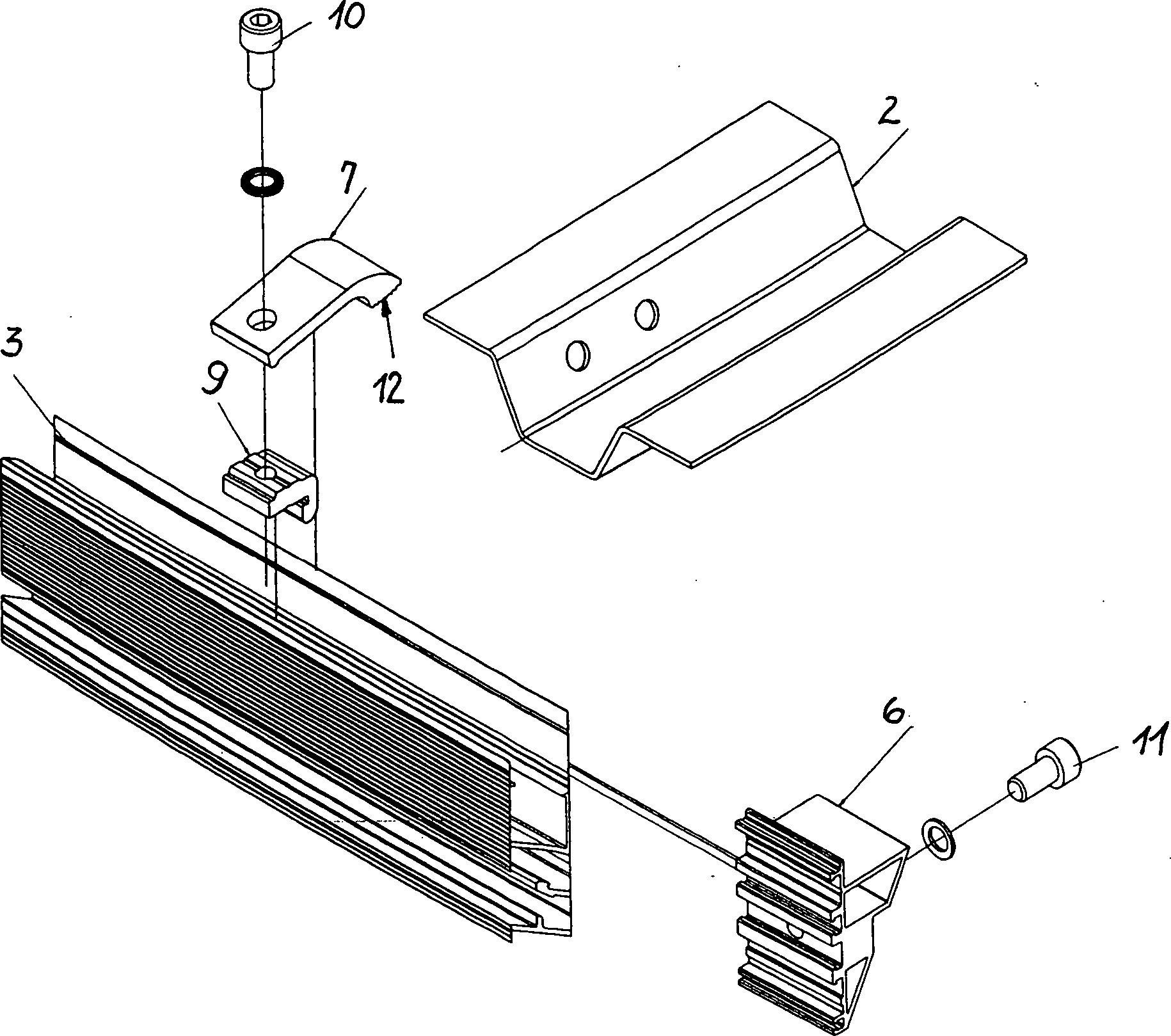
Vorrichtung zur Befestigung von rahmenlosem Photovoltaiklaminat (1), das auf der Unterseite Flächenstabilisierungsträger (2) mit einem Hohlprofil aufweist, bestehend aus mindestens paarweise und beabstandet angeordneten Montageprofilschienen (3), die jeweils über eine Anschlußprofilierung (4) für eine Befestigung an einem Bauwerk verfügen und eine Anschlußprofilierung (5) für den Anschluss eines Auflagers (6) für einen Flächenstabilisierungsträger (2) des Photovoltaiklaminates (1) aufweisen, wobei Mittel vorgesehen sind, die den Flächenstabilisierungsträger (2) am Auflager (6) fixieren.contraption for mounting of frameless photovoltaic laminate (1), the the underside area stabilization carrier (2) having a hollow profile, consisting of at least in pairs and spaced mounting mounting rails (3), each over a connection profiling (4) for a fastening to have a building and a connection profiling (5) for the connection of a support (6) for a surface stabilization support (2) of the photovoltaic laminate (1) having means are provided which the Flächenstabilisierungsträger (2) on the support (6).
Description
Die Erfindung betrifft die Befestigung von rahmenlosem Photovoltaiklaminat (Dünnschichtmodule) auf oder an einem Traggerüst.The The invention relates to the attachment of frameless photovoltaic laminate (Thin-film modules) on or on a support frame.
Photovoltaiklaminat, bestehend aus einer Photovoltaikfolie, die zwischen Glasplatten verklebt wurde, wird heute als Dünnschichtmodul in Flächengrößen von 1300 × 1100 mm2 (quater) und bis zum 4-fachen dieser Fläche angeboten. Ein derartiges Laminat ist aufgrund der notwendigen Glasstabilisierung entweder teuer und schwer oder muß in der Fläche durch Stabilisierungsträger gestützt werden.Photovoltaic laminate, consisting of a photovoltaic film that has been glued between glass plates, is now offered as a thin-film module in surface sizes of 1300 × 1100 mm 2 (quater) and up to 4 times this area. Such a laminate is either expensive and heavy due to the necessary glass stabilization or must be supported in the surface by stabilizing supports.
Letzteres wird bei einem handelsüblichen Dünnschichtmodul mit Trapezprofilen erreicht, die unterhalb des Laminates und mit diesem verbunden angeordnet sind. Die verwendeten Trapezprofile sind auf der längeren Trapezseite offen und die seitlichen Schenkel in dieser Ebene nach außen angewinkelt, so dass darauf das Laminat abgestützt werden kann und hier auch die vorzugsweise Klebeverbindung zwischen Trapezprofil und Laminat herstellbar ist.The latter is in a commercially available thin film module achieved with trapezoidal profiles, which are below the laminate and with this are arranged connected. The trapezoidal profiles used are open on the longer side of the trapezium and the lateral legs in this plane angled outwards, so that on it The laminate can be supported and here also preferably Adhesive connection between trapezoidal profile and laminate can be produced.
Aus dem Bereich von gerahmten Photovoltaikmodulen sind verschiedene Traggerüste bekannt, wobei sich technisch und wirtschaftlich als optimal solche erwiesen haben, die stranggepreßte Profilträger verwenden, wobei die Profile Befestigungsmöglichkeiten für mit dem Rahmen des Modules verbindbare Befestigungsmittel aufweisen.Out The range of framed photovoltaic modules are different Shoring known, being technically and economically have proven to be optimal, the extruded profile beam use, with the profiles mounting options for connectable with the frame of the module fasteners exhibit.
Ein
derartiges Montagesystem ist aus der
Mit
der
auf der einen Seite eine Anschlussprofilierung
für eine Befestigung der Montageprofilschiene vorhanden
ist und
auf der gegenüberliegenden Seite Anschlussprofile so
strukturiert angeordnet sind, dass eine zweite Montageprofilschiene
mit dem selben Profilquerschnitt und um 180° gedreht durch
Ineinanderschieben der Anschlussprofile formschlüssig mit
der ersten Montageprofilschiene verbindbar ist.With the
on the one hand a connection profiling for attachment of the mounting rail is present and
On the opposite side connection profiles are arranged structured so that a second mounting rail with the same profile cross-section and rotated by 180 ° by telescoping the connection profiles is positively connected to the first mounting rail.
Aufgabe der Erfindung ist es, derartige Montageprofilschienensysteme für die Montage der Dünnschichtmodule einzusetzen und dabei insbesondere das beschriebene optimierte Montageprofilschienensystem mit formschlüssig einsetzbaren Gewindesteinen für das genannte großflächige flächenstabilisierte rahmenlose Photovoltaiklaminat verwendbar zu machen.task The invention is to such mounting profile rail systems for to use the assembly of thin-film modules and thereby in particular the described optimized mounting profile rail system with form-fitting threaded rods for the aforementioned large-area surface-stabilized frameless photovoltaic laminate usable.
Gelöst wird diese Aufgabe mit den Merkmalen des Anspruches 1, vorteilhafte Ausgestaltungen sind Gegenstand der Unteransprüche.Solved This object is achieved with the features of claim 1, advantageous Embodiments are the subject of the dependent claims.
Erfindungsgemäß wird eine Vorrichtung zur Befestigung von rahmenlosem Photovoltaiklaminat, das auf der Unterseite Flächenstabilisierungsträger mit einem Hohlprofil aufweist, vorgeschlagen, die aus mindestens paarweise und beabstandet angeordneten Montageprofilschienen besteht, die jeweils über eine Anschlußprofilierung für eine Befestigung an einem Bauwerk verfügen und eine Anschlußprofilierung für ein Auflager für einen Flächenstabilisierungsträger des Photovoltaiklaminates aufweisen, wobei Mittel vorgesehen sind, die den Flächenstabilisierungsträger am Auflager fixieren.According to the invention a device for fixing frameless photovoltaic laminate, the on the bottom surface stabilizer with a hollow profile, proposed that from at least in pairs and spaced arranged mounting rails, the in each case via a connection profiling for have an attachment to a structure and a connection profiling for a support for a Flächenstabilsträgersträger of the photovoltaic laminate, wherein means are provided, the surface stabilizer support on the support fix.
Als
Montageprofilschienen werden dabei die eingangs beschriebenen verwendet,
die über eine im Wesentlichen rechteckige Mantellinie verfügen,
wobei
auf der einen Seite die Anschlussprofilierung für
die Befestigung der Montageprofilschiene vorhanden ist, auf der
gegenüberliegenden Seite eine Anschlussprofilierung, deren
Profile so strukturiert angeordnet sind, dass eine zweite Montageprofilschiene
mit dem selben Profilquerschnitt und um 180° gedreht durch Ineinanderschieben
der Anschlussprofile formschlüssig mit der ersten Montageprofilschiene
verbindbar ist und sich im Kopfbereich eine Anschlussprofilierung
für den Eingriff und die Befestigung von Gewindesteinen
befindet.As mounting profile rails while those described above are used, which have a substantially rectangular generatrix, wherein
on the one hand, the connection profiling for the attachment of the mounting rail is present, on the opposite side a connection profile whose profiles are arranged so structured that a second mounting rail with the same profile cross-section and rotated by 180 ° by telescoping the connection profiles form fit with the first mounting rail is connectable and in the head area a connection profiling for the engagement and the attachment of threaded rods is.
Diese Montageprofilschiene bietet unterschiedliche Möglichkeiten für die Herstellung einer Verbindung mit dem Flächenstabilisierungsträger oder einem in den Flächenstabilisierungsträger in Trägerlängsrichtung angeordneten Verlängerungsprofil.These Mounting rail offers different possibilities for the preparation of a compound with the Flächenstabilisierungsträger or one in the area stabilization carrier in the carrier longitudinal direction arranged extension profile.
Bei einer ersten Ausführung ist vorgesehen, dass das Auflager für den Flächenstabilisierungsträger oder dessen Verlängerungsprofil aus einer Profilschiene oder Profilschienenabschnitten besteht, die in die seitliche Anschlußprofilierung der Montageprofilschiene einschiebbar und an dieser fixierbar sind. Dabei kann die Auflage eine ebene Fläche oder eine in Teilen als ein Negativprofil des Flächenstabilisierungsträgers oder von dessen Verlängerungsprofil ausgebildete Form aufweisen.at A first embodiment provides that the support for the area stabilization carrier or its extension profile from a rail or profile rail sections, which in the lateral connection profiling the mounting rail can be inserted and fixed to this. there the overlay may be a flat surface or one in parts as a negative profile of the surface stabilizer carrier or formed by its extension profile form.
Das Negativprofil kann auch ein Adapterteil sein, das am seitlich an der Montageprofilschiene angeordneten Auflager angeordnet ist. Diese Zweiteilung in Auflager- und Adapterteil hat besondere Bedeutung dann, wenn alle Teile durch Ablängen von stranggepressten Profilen herstellbar sein sollen, denn diese Technologie ist dann auch für das Auflage- und das Adapterteil verwendbar.The negative profile can also be an adapter part, which is arranged on the side of the mounting rail arranged support. This division into support and adapter part has special Be meaning when all parts should be produced by cutting to length extruded profiles, because this technology is then also for the support and the adapter part usable.
Als Mittel zur Fixierung des Flächenstabilisierungsträgers oder von dessen Verlängerungsprofil am Auflager ist ein Spannbügel vorgesehen, der an der Montageprofilschiene angeordnet gegen den Flächenstabilisierungsträger oder dessen Verlängerungsprofil verspannbar ist und den Flächenstabilisierungsträger oder dessen Verlängerungsprofil dabei gegen das Auflager bzw. in das Negativprofil presst.When Means for fixing the Flächenstabilisierungssträgers or from its extension profile on the support is a Clamp provided on the mounting rail arranged against the Flächenstabilisierungsträger or whose extension profile is braced and the Surface stabilizer or its extension profile presses against the support or in the negative profile.
Als Anschluss für den Spannbügel wird bevorzugt die Anschlußprofilierung für den Gewindestein genutzt, wobei der Spannbügel durch den in das Gewinde des Gewindesteines einsetzbaren Bolzen beim Verspannen des Gewindesteines auf den Flächenstabilisierungsträger oder dessen Verlängerungsprofil gepresst wird.When Connection for the clamping bracket is preferred Connection profiling used for the threaded rod, the tension bracket being inserted through the thread of the threaded rod insertable bolt when tightening the threaded rod on the Flächenstabilisierungsträger or its extension profile is pressed.
Bei einer anderen bevorzugten Ausführung besteht das Auflager aus einem Adapterteil mit einem Negativprofil des Flächenstabilisierungsträgers oder dessen Verlängerungsprofils und wird seitlich von der Auflage mit dem oder den Bolzen zur Befestigung des oder der Gewindesteine an der Montageprofilschiene angeschraubt.at another preferred embodiment is the support from an adapter part with a negative profile of the surface stabilization carrier or its extension profile and is laterally of the support with the or the bolt for fixing the or Threaded studs screwed to the mounting rail.
Bei einem solchen Auflager mit einem Negativprofil des Flächenstabilisierungsträgers oder dessen Verlängerungsprofil sind zur Fixierung Verbindungselemente zwischen dem Negativprofil des Auflagers und dem Flächenstabilisierungsträger oder dessen Verlängerungsprofil vorgesehen.at Such a support with a negative profile of the surface stabilization support or its extension profile are for fixing fasteners between the negative profile of the support and the Flächenstabilisierungsträger or its extension profile provided.
Sowohl unter dem Gesichtspunkt einer möglichst spannugsfreien Lagerung des Flächenstabilisierungsträgers oder dessen Verlängerungsprofil als auch unter dem Gesichtspunkt des Einsatzes möglicherweise unterschiedlicher Metalle für das Auflager (Aluminium) und die Flächenstabilisierungsträger oder Verlängerungsprofile (Stahl), ist es von Vorteil, wenn zwischen der Auflagefläche des Auflagers und dem Flächenstabilisierungsträgers oder dessen Verlängerungsprofil ein Isoliermaterial, vorzugsweise eine Gummilage, angeordnet ist.Either from the point of view of a tension-free as possible Storage of surface stabilizer or its extension profile as well as from the point of view the use of possibly different metals for the support (aluminum) and the Flächenstabilisierungsträger or Extension profiles (steel), it is advantageous if between the bearing surface of the support and the Flächenstabilisierungssträgers or its extension profile an insulating material, preferably one Rubber layer, is arranged.
Die Erfindung soll an Ausführungsbeispielen erläutert werden. Es zeigenThe The invention will be explained with reference to exemplary embodiments become. Show it
In
den dargestellten Ausführungsbeispielen wiederholen sich
das rahmenlose Photovoltaiklaminat
Das
Hohlprofil des Flächenstabilisierungsträgers
Die
Montageprofilschiene
Die
Der
Spannbügel
Der
Spannbügel
Der
Anschluss des Spannbügels
Als
Auflager
Das
Auflager
In
der dargestellten Ausführung ist die Auflagerfläche
für den Flächenstabilisierungsträger
Weiter
wird dargestellt, dass das Auflager
In
den
Das
Negativprofil des Auflagers
Zwischen
dem Flächenstabilisierungsträger
- 11
- Photovoltaiklaminatphotovoltaic laminate
- 22
- FlächenstabilisierungsträgerSurface stabilizing support
- 33
- MontageprofilschieneMounting rail
- 44
- Anschlussprofilierung für Bauwerksbefestigungconnection profiling for building fortification
- 55
- Anschlussprofilierung für Auflagerconnection profiling for supports
- 66
- AuflagerIn stock
- 77
- Spannbügeltensioning bow
- 88th
- Anschlussprofilierung für Gewindesteinconnection profiling for threaded stud
- 99
- Gewindesteinthread Stein
- 1010
- Bolzen für Gewindesteinbolt for threaded stud
- 1111
- Bolzen für die Fixierung des Auflagersbolt for fixing the support
- 1212
- Auflagefläche des Spannbügelsbearing surface of the tension bracket
- 1313
- Verlängerungsprofilextension profile
- 1414
- Adapteradapter
- 1515
- Verbindungselementefasteners
ZITATE ENTHALTEN IN DER BESCHREIBUNGQUOTES INCLUDE IN THE DESCRIPTION
Diese Liste der vom Anmelder aufgeführten Dokumente wurde automatisiert erzeugt und ist ausschließlich zur besseren Information des Lesers aufgenommen. Die Liste ist nicht Bestandteil der deutschen Patent- bzw. Gebrauchsmusteranmeldung. Das DPMA übernimmt keinerlei Haftung für etwaige Fehler oder Auslassungen.This list The documents listed by the applicant have been automated generated and is solely for better information recorded by the reader. The list is not part of the German Patent or utility model application. The DPMA takes over no liability for any errors or omissions.
Zitierte PatentliteraturCited patent literature
- - DE 2005/002331 [0005] - DE 2005/002331 [0005]
- - DE 2008/000593 [0006] - DE 2008/000593 [0006]
- - DE 202007006021 U1 [0006] - DE 202007006021 U1 [0006]
Claims (17)
Priority Applications (1)
| Application Number | Priority Date | Filing Date | Title |
|---|---|---|---|
| DE202008009864U DE202008009864U1 (en) | 2008-07-21 | 2008-07-21 | Device for fixing surface-stabilized photovoltaic laminates |
Applications Claiming Priority (1)
| Application Number | Priority Date | Filing Date | Title |
|---|---|---|---|
| DE202008009864U DE202008009864U1 (en) | 2008-07-21 | 2008-07-21 | Device for fixing surface-stabilized photovoltaic laminates |
Publications (1)
| Publication Number | Publication Date |
|---|---|
| DE202008009864U1 true DE202008009864U1 (en) | 2008-10-09 |
Family
ID=39829888
Family Applications (1)
| Application Number | Title | Priority Date | Filing Date |
|---|---|---|---|
| DE202008009864U Expired - Lifetime DE202008009864U1 (en) | 2008-07-21 | 2008-07-21 | Device for fixing surface-stabilized photovoltaic laminates |
Country Status (1)
| Country | Link |
|---|---|
| DE (1) | DE202008009864U1 (en) |
Cited By (10)
| Publication number | Priority date | Publication date | Assignee | Title |
|---|---|---|---|---|
| EP2187448A2 (en) * | 2008-10-21 | 2010-05-19 | Sunfilm AG | System for attaching, solar assembly and method for filling a solar assembly |
| ITMI20090757A1 (en) * | 2009-05-04 | 2010-11-05 | Ren Electron Srl | APPARATUS FOR COVERING STRUCTURES WITH PHOTOVOLTAIC PANELS |
| DE102011084215A1 (en) * | 2011-06-07 | 2012-12-13 | Mounting Systems Gmbh | Mounting system and mounting arrangement for a solar module assembly and fastener socket and fastener adapter |
| US10060133B2 (en) | 2010-01-25 | 2018-08-28 | Rillito River Solar, Llc | Roof mount assembly |
| US10090801B2 (en) | 2010-01-25 | 2018-10-02 | Rillito River Solar, Inc. | Roofing grommet forming a seal between a roof-mounted structure and a roof |
| US10151114B2 (en) | 2010-01-25 | 2018-12-11 | Rillito River Solar, Llc | Roof mount assembly |
| CN109926810A (en) * | 2019-03-29 | 2019-06-25 | 北京奥普科星技术有限公司 | A kind of photovoltaic short frame squeezes corner brace mechanism automatically |
| US10472828B2 (en) | 2010-01-25 | 2019-11-12 | EcoFasten Solar, LLC | Roof mounting system |
| US10505492B2 (en) | 2016-02-12 | 2019-12-10 | Solarcity Corporation | Building integrated photovoltaic roofing assemblies and associated systems and methods |
| US11201581B2 (en) | 2010-01-25 | 2021-12-14 | EcoFasten Solar, LLC | Roof mounting system |
Citations (2)
| Publication number | Priority date | Publication date | Assignee | Title |
|---|---|---|---|---|
| WO2006072230A1 (en) | 2005-01-10 | 2006-07-13 | Conergy Ag | Threaded slider mounting system |
| DE202007006021U1 (en) | 2007-04-19 | 2007-07-19 | Conergy Ag | Connectable mounting rail (base rail) |
-
2008
- 2008-07-21 DE DE202008009864U patent/DE202008009864U1/en not_active Expired - Lifetime
Patent Citations (3)
| Publication number | Priority date | Publication date | Assignee | Title |
|---|---|---|---|---|
| WO2006072230A1 (en) | 2005-01-10 | 2006-07-13 | Conergy Ag | Threaded slider mounting system |
| DE202007006021U1 (en) | 2007-04-19 | 2007-07-19 | Conergy Ag | Connectable mounting rail (base rail) |
| WO2008128507A1 (en) | 2007-04-19 | 2008-10-30 | Conergy Ag | Connectable profiled mounting rail (base rail) |
Cited By (22)
| Publication number | Priority date | Publication date | Assignee | Title |
|---|---|---|---|---|
| EP2187448A2 (en) * | 2008-10-21 | 2010-05-19 | Sunfilm AG | System for attaching, solar assembly and method for filling a solar assembly |
| EP2187448A3 (en) * | 2008-10-21 | 2011-07-13 | Sunfilm AG | System for attaching, solar assembly and method for filling a solar assembly |
| US11851884B2 (en) | 2009-02-11 | 2023-12-26 | EcoFasten Solar, LLC | Roof mount assembly |
| US11773597B2 (en) | 2009-02-11 | 2023-10-03 | EcoFasten Solar, LLC | Roof mounting system |
| US11692352B2 (en) | 2009-02-11 | 2023-07-04 | EcoFasten Solar, LLC | Roof mount assembly |
| US11271516B2 (en) | 2009-02-11 | 2022-03-08 | EcoFasten Solar, LLC | Roof mounting system |
| ITMI20090757A1 (en) * | 2009-05-04 | 2010-11-05 | Ren Electron Srl | APPARATUS FOR COVERING STRUCTURES WITH PHOTOVOLTAIC PANELS |
| US11201581B2 (en) | 2010-01-25 | 2021-12-14 | EcoFasten Solar, LLC | Roof mounting system |
| US11118353B2 (en) | 2010-01-25 | 2021-09-14 | EcoFasten Solar, LLC | Roof mount assembly |
| US10472828B2 (en) | 2010-01-25 | 2019-11-12 | EcoFasten Solar, LLC | Roof mounting system |
| US10060133B2 (en) | 2010-01-25 | 2018-08-28 | Rillito River Solar, Llc | Roof mount assembly |
| US10594251B2 (en) | 2010-01-25 | 2020-03-17 | EcoFasten Solar, LLC | Roof mounting system |
| US10676929B2 (en) | 2010-01-25 | 2020-06-09 | EcoFasten Solar, LLC | Roof mount assembly |
| US10763777B2 (en) | 2010-01-25 | 2020-09-01 | EcoFasten Solar, LLC | Roof mounting system |
| US10090801B2 (en) | 2010-01-25 | 2018-10-02 | Rillito River Solar, Inc. | Roofing grommet forming a seal between a roof-mounted structure and a roof |
| US10218304B2 (en) | 2010-01-25 | 2019-02-26 | Rillito River Solar, Llc | Roof mounting system |
| US11205990B2 (en) | 2010-01-25 | 2021-12-21 | EcoFasten Solar, LLC | Roof mounting system |
| US10151114B2 (en) | 2010-01-25 | 2018-12-11 | Rillito River Solar, Llc | Roof mount assembly |
| DE102011084215A1 (en) * | 2011-06-07 | 2012-12-13 | Mounting Systems Gmbh | Mounting system and mounting arrangement for a solar module assembly and fastener socket and fastener adapter |
| US10505492B2 (en) | 2016-02-12 | 2019-12-10 | Solarcity Corporation | Building integrated photovoltaic roofing assemblies and associated systems and methods |
| CN109926810A (en) * | 2019-03-29 | 2019-06-25 | 北京奥普科星技术有限公司 | A kind of photovoltaic short frame squeezes corner brace mechanism automatically |
| CN109926810B (en) * | 2019-03-29 | 2023-11-03 | 北京奥普科星技术有限公司 | Automatic extrusion angle sign indicating number mechanism of photovoltaic short frame |
Similar Documents
| Publication | Publication Date | Title |
|---|---|---|
| DE202008009864U1 (en) | Device for fixing surface-stabilized photovoltaic laminates | |
| EP2544573B1 (en) | Method of mounting a shower partition | |
| DE202010011235U1 (en) | Clamping device and solar module unit | |
| DE102007039755A1 (en) | Fastener for fastening solar elements on e.g. roof, has longitudinally running elevations in inner sides of top hat rails, and mounting rails with side provided with point or line shaped running knurled or roughened area | |
| DE202013005956U1 (en) | Corner connector for a Unterbaurahrnen, in particular for the reception of laying nests | |
| DE202010012937U1 (en) | fastening system | |
| DE202010008421U1 (en) | Support system for solar modules | |
| DE202019101409U1 (en) | Profile system for forming a sub-frame for receiving floor coverings and connecting element | |
| DE202010010597U1 (en) | Clamping device for fixing framed solar modules | |
| DE202011002283U1 (en) | Trapezoidal shoe-shaped mounting for roof structures on a sandwich roof element | |
| DE202012002547U1 (en) | Device for supporting solar modules | |
| DE102014107510A1 (en) | Carrier structure for a motor vehicle | |
| EP2775231B1 (en) | Mounting bracket | |
| DE102012102243A1 (en) | Frame kit for assembling solar module device at e.g. building roof, has stretched additive laths and frame lath comprising connection unit for partially interconnecting additive lath and frame lath along frame lath | |
| DE102019202621A1 (en) | Roof construction for a motor vehicle with at least one roof rail | |
| DE102011009239A1 (en) | Photovoltaic module has three upper bevel portions that are connected with three lower bevel portions to form triangular section | |
| DE4004055C2 (en) | Device for sound-absorbing fastening of pipelines | |
| AT12030U1 (en) | DEVICE FOR FIXING PROFILES TO A SUB-CONSTRUCTION | |
| DE202008009758U1 (en) | Frame for a photovoltaic solar module | |
| DE102014102162A1 (en) | Fasteners for hanging sound absorbers and sound absorber system | |
| DE102010060666A1 (en) | System for spaced fastening plate-shaped modules i.e. solar modules, at trapezoid roof, has nut rotating when attracting screw against bore, so that supporting angle pushes away over screw at edge of bore against force applied by fastener | |
| DE202011105896U1 (en) | Solar module holder for a ballast receiving container by means of a divisible mounting element | |
| EP2441622A1 (en) | Roof-rack holder | |
| AT512429B1 (en) | ASSEMBLY ELEMENT FOR A TENSIONING FRAME OF A TENSIONING FRAME AND METHOD FOR FIXING A TIGHTENING FRAME PART OF A TENSIONING FRAME THROUGH THE ASSEMBLY ELEMENT | |
| DE102013107396B4 (en) | Device for securing transport |
Legal Events
| Date | Code | Title | Description |
|---|---|---|---|
| R207 | Utility model specification |
Effective date: 20081113 |
|
| R081 | Change of applicant/patentee |
Owner name: MOUNTING SYSTEMS GMBH, DE Free format text: FORMER OWNER: CONERGY AG, 15834 RANGSDORF, DE Effective date: 20110728 |
|
| R082 | Change of representative |
Representative=s name: KIETZMANN VOSSEBERG ROEHNICKE PATENTANWAELTE PARTN Representative=s name: KIETZMANN VOSSEBERG ROEHNICKE PATENTANWAELTE P, DE Effective date: 20110728 |
|
| R150 | Utility model maintained after payment of first maintenance fee after three years | ||
| R150 | Utility model maintained after payment of first maintenance fee after three years |
Effective date: 20111130 |
|
| R151 | Utility model maintained after payment of second maintenance fee after six years | ||
| R079 | Amendment of ipc main class |
Free format text: PREVIOUS MAIN CLASS: H01L0031050000 Ipc: H02S0020220000 |
|
| R079 | Amendment of ipc main class |
Free format text: PREVIOUS MAIN CLASS: H01L0031050000 Ipc: H02S0020220000 Effective date: 20141016 |
|
| R151 | Utility model maintained after payment of second maintenance fee after six years |
Effective date: 20141002 |
|
| R158 | Lapse of ip right after 8 years |