WO2025142256A1 - 実装装置および調整方法 - Google Patents
実装装置および調整方法 Download PDFInfo
- Publication number
- WO2025142256A1 WO2025142256A1 PCT/JP2024/041662 JP2024041662W WO2025142256A1 WO 2025142256 A1 WO2025142256 A1 WO 2025142256A1 JP 2024041662 W JP2024041662 W JP 2024041662W WO 2025142256 A1 WO2025142256 A1 WO 2025142256A1
- Authority
- WO
- WIPO (PCT)
- Prior art keywords
- heating
- substrate
- integrated package
- heat
- area
- Prior art date
- Legal status (The legal status is an assumption and is not a legal conclusion. Google has not performed a legal analysis and makes no representation as to the accuracy of the status listed.)
- Pending
Links
Images






Classifications
-
- H—ELECTRICITY
- H05—ELECTRIC TECHNIQUES NOT OTHERWISE PROVIDED FOR
- H05K—PRINTED CIRCUITS; CASINGS OR CONSTRUCTIONAL DETAILS OF ELECTRIC APPARATUS; MANUFACTURE OF ASSEMBLAGES OF ELECTRICAL COMPONENTS
- H05K3/00—Apparatus or processes for manufacturing printed circuits
- H05K3/30—Assembling printed circuits with electric components, e.g. with resistors
- H05K3/32—Assembling printed circuits with electric components, e.g. with resistors electrically connecting electric components or wires to printed circuits
- H05K3/34—Assembling printed circuits with electric components, e.g. with resistors electrically connecting electric components or wires to printed circuits by soldering
-
- H—ELECTRICITY
- H10—SEMICONDUCTOR DEVICES; ELECTRIC SOLID-STATE DEVICES NOT OTHERWISE PROVIDED FOR
- H10W—GENERIC PACKAGES, INTERCONNECTIONS, CONNECTORS OR OTHER CONSTRUCTIONAL DETAILS OF DEVICES COVERED BY CLASS H10
- H10W72/00—Interconnections or connectors in packages
- H10W72/071—Connecting or disconnecting
Definitions
- the present invention relates to a mounting device that mounts an integrated package on a substrate and a method for adjusting the mounting device.
- a mounting device that mounts a semiconductor chip on a substrate is known.
- the mounting device places the semiconductor chip at a predetermined position on a substrate on a stage, and connects the semiconductor chip to the substrate by pressing the semiconductor chip against the substrate while melting the bumps of the semiconductor chip with heat.
- the mounting device (semiconductor manufacturing device) described in Patent Document 1 has a bonding head that mounts the semiconductor chip on the substrate, an attachment that is provided on the bonding head and that sucks the semiconductor chip, and a heating unit that heats the attachment.
- the heating unit has a first heating area and a second heating area that horizontally surrounds the first heating area.
- the mounting device makes the temperature distribution of the semiconductor chip uniform by independently controlling the temperatures of the first heating area and the second heating area.
- the mounting device described in Patent Document 1 makes the temperature distribution of the semiconductor chip uniform by setting the heating temperature of the second heating area, which heats the peripheral parts of the semiconductor chip, which are more likely to drop in temperature due to heat dissipation compared to the central part of the semiconductor chip, higher than the heating temperature of the first heating area, which heats the central part of the semiconductor chip.
- the integrated parts of the semiconductor chips, which have high thermal conductivity, and the resin parts, which have lower thermal conductivity than the integrated parts of the semiconductor chips are unevenly located in the integrated package.
- the integrated package has a more complex distribution of thermal conductivity than a single semiconductor chip. Therefore, in the mounting device described in Patent Document 1, it was sometimes difficult to achieve uniform heating to suppress poor connection between the substrate and the integrated package, uneven gaps between the substrate and the integrated package, etc.
- the object of the present invention is to provide a mounting device and an adjustment method thereof that can suppress temperature variations when an integrated package with non-uniform thermal conductivity is heated and suppress poor connection of the integrated package to a substrate.
- the inventors have investigated the configuration of a mounting device that can suppress temperature variations when an integrated package with non-uniform thermal conductivity is heated and can suppress poor connection of the integrated package to a substrate. As a result of extensive investigation, the inventors have come up with the following configuration.
- a mounting device includes a stage on which at least one of an integrated package in which multiple semiconductor chips are integrated and molded and a substrate on which the integrated package is mounted is mounted, a pressing unit disposed opposite the stage and moving relatively toward the stage to press the substrate and the integrated package, a first attachment supported by the stage and contacting either the substrate or the integrated package from the direction of movement of the pressing unit, a second attachment supported by the pressing unit and contacting the other of the substrate or the integrated package from the direction of movement of the pressing unit, a first heating unit supported by the stage and heating the first attachment, and a second heating unit supported by the pressing unit and heating the second attachment.
- At least one of the first heating section and the second heating section has a plurality of heating regions based on the distribution of the pressing direction thermal conductivity, which is the thermal conductivity of the integrated package in the pressing direction of the pressing section.
- the plurality of heating regions are each configured to generate heat at different amounts of heat per unit time and unit area.
- At least one of the first heating unit and the second heating unit has multiple heating regions based on the distribution of the pressure direction thermal conductivity of the integrated package.
- at least one of the first heating unit and the second heating unit heats the integrated package with a heat amount based on the pressure direction thermal conductivity of the integrated package.
- the mounting device adjusts the amount of heat transferred from the substrate to the integrated package, which is determined by the pressure direction thermal conductivity and the temperature difference between the substrate and the integrated package, by heating with multiple heating regions. This makes it possible to suppress temperature variations when an integrated package with non-uniform thermal conductivity is heated uniformly, and to suppress poor connection of the integrated package to the substrate.
- the mounting device of the present invention includes the following configuration: When viewed in the pressing direction, the multiple heating regions overlap with each other at portions of the integrated package that have different predetermined ranges of thermal conductivity in the pressing direction.
- the multiple heating regions are configured to correspond to regions of pressure direction thermal conductivity, with a portion of the integrated package whose pressure direction thermal conductivity is within a predetermined range being one region.
- at least one of the first heating section and the second heating section can transfer an appropriate amount of heat for adjusting the temperature of each pressure direction thermal conductivity region by adding heat to each pressure direction thermal conductivity region of the integrated package. This makes it possible to suppress temperature variations that occur when an integrated package with non-uniform thermal conductivity is uniformly heated, and to suppress poor connection of the integrated package to a substrate.
- the mounting device of the present invention includes the following configuration:
- the multiple heating regions are configured to generate heat with an amount of heat proportional to the magnitude of the thermal conductivity in the pressing direction of the integrated packages that overlap when viewed in the pressing direction.
- the heating area when the heating area contacts at least one of the substrate and the integrated package, the heating area has a higher heat value in a portion overlapping a portion of the integrated package having a higher heat value in the pressing direction than the other portions than the heating area overlapping the other portions.
- This allows the mounting device to suppress a temperature drop in the substrate by heating a portion in which heat is more easily transferred from the substrate to the integrated package than the other portions with a higher heat value than the other portions.
- the heating area has a lower heat value in the pressing direction than the heating area overlapping the other portions than the heating area overlapping the other portions.
- the mounting device of the present invention includes the following configuration:
- the first heating section has a single heating area that generates heat at a predetermined amount of heat per unit time and unit area, and heats the substrate via the first attachment with the single heating area that generates heat with a uniform amount of heat.
- the second heating section has the multiple heating areas, and heats the integrated package via the second attachment with the multiple heating areas that generate heat with different amounts of heat based on the distribution of thermal conductivity in the pressing direction of the integrated package.
- the integrated package to which heat is transferred from the substrate uniformly heated by the first heating section, is heated by the multiple heating regions of the second heating section based on the distribution of pressure direction thermal conductivity.
- the mounting device heats the integrated package with an amount of heat based on the pressure direction thermal conductivity for each region with a predetermined range of pressure direction thermal conductivity, thereby making it possible to adjust the amount of heat transferred from the substrate to the integrated package. This makes it possible to suppress temperature variations when an integrated package with non-uniform thermal conductivity is heated, and to suppress poor connection of the integrated package to the substrate.
- the mounting device of the present invention includes the following configuration: It has a control unit that controls the second heating unit.
- the first attachment has a temperature sensor at a position that overlaps with the multiple heating areas when viewed in the pressing direction.
- the control unit controls the amount of heat generated for each of the multiple heating areas so that the temperature detected by the temperature sensor is within a predetermined range.
- the mounting device controls the amount of heat generated by the multiple heating regions so that the temperature of the first attachment holding the substrate falls within a predetermined range.
- the mounting device adds an amount of heat to the substrate according to the amount of heat transferred from the substrate to the integrated package by using the multiple heating regions to heat the substrate based on the temperature of the substrate, which varies depending on the difference in thermal conductivity of the integrated package in the pressing direction. This makes it possible to suppress temperature variations when an integrated package with non-uniform thermal conductivity is heated, and to suppress poor connection of the integrated package to the substrate.
- This is a method for adjusting the amount of heat generated by a first heating section that heats a substrate and an integrated package placed on the substrate from one side of the placement direction, and a second heating section that has multiple heating regions that heats the substrate from the other side of the placement direction.
- the adjustment method includes a first temperature adjustment process for heating the substrate and the integrated package by a first heating unit and a first adjustment heating area, which is a heating area for adjusting the amount of heat generated among the multiple heating areas of the second heating unit, and adjusting the amount of heat generated by the first adjustment heating area so that the temperature of the area of the substrate overlapping with the first adjustment heating area, as viewed in the placement direction, falls within a target temperature range; and a second adjustment heating area for heating the substrate and the integrated package by the first heating unit and the first adjustment heating area, which generates heat with the amount of heat generated adjusted in the first temperature adjustment process, and adjusting the amount of heat generated by the first adjustment heating area, which is a heating area of the second heating unit whose amount of heat generated is not adjusted in the first temperature adjustment process.
- the method includes a second temperature adjustment process for heating the substrate and the integrated package by the second temperature adjustment process and adjusting the amount of heat generated by the second temperature adjustment process so that the temperature of the substrate area overlapping the second temperature adjustment process falls within a target temperature range, as viewed in the placement direction; and a readjustment process for adjusting the amounts of heat generated by the first temperature adjustment process and the second temperature adjustment process so that the temperature of the substrate area overlapping the first temperature adjustment process and the temperature of the substrate area overlapping the second temperature adjustment process fall within a target temperature range, as viewed in the placement direction.
- the heat generation amount of the second heating unit having multiple heating areas is individually adjusted by the first temperature adjustment process and the second temperature adjustment process, and then the heat generation amount of the multiple heating areas whose heat generation amount was adjusted in the first temperature adjustment process and the second temperature adjustment process is readjusted by the readjustment process.
- the adjustment method adjusts the heat generation amount of each heating area taking into consideration the influence between the heating areas set based on the thermal conductivity in the pressing direction (placement direction) between the substrate and the integrated package. This makes it possible to suppress temperature variations when an integrated package with non-uniform thermal conductivity is uniformly heated, and to suppress poor connection of the integrated package to the substrate.
- connection As used herein, the terms “attached,” “connected,” “coupled,” and/or their equivalents are used broadly to encompass both “direct and indirect” attachments, connections, and couplings. Additionally, “connected” and “coupled” are not limited to physical or mechanical connections or couplings, but can include direct or indirect electrical connections or couplings.
- an integrated package means a package in which multiple semiconductor chips are integrated and molded on a package substrate.
- the integrated package includes a 2.5D integrated package in which two or more active semiconductor chips are arranged side by side on a silicon interposer (or an organic interposer) in which wiring is processed on a silicon substrate, and a 3D integrated package in which two or more active semiconductor chips are integrated by die stacking.
- the integrated package is a package in which an integrated circuit configured by heterogeneous integration is resin molded. Note that a configuration in which multiple semiconductor chips are connected by a silicon bridge of a package substrate may also be used.
- the integrated package may have any structure as long as it is a package in which multiple semiconductor chips are integrated and molded.
- substrate refers to a substrate on which an integrated package is mounted and on which a wiring circuit made of a material such as silicon, ceramics, or resin is patterned.
- the substrate has wiring made of a conductor.
- the integrated circuit and the substrate are connected by welding bumps, which are protruding connection electrodes.
- the pressure direction thermal conductivity of the integrated package refers to the stacking direction of the semiconductor chip and the silicon interposer in the integrated package, and means the average thermal conductivity per unit area in the pressing direction by the pressing part of the mounting device.
- the pressure direction thermal conductivity of the integrated package differs between the part where the semiconductor chips are stacked and the part where only the silicon interposer is present, as viewed in the pressing direction, because multiple silicon semiconductor chips are unevenly integrated. Therefore, the pressure direction thermal conductivity of the integrated package is distributed unevenly in the pressing direction based on the shape and stacking direction of the semiconductor chips of the integrated package. In the following embodiments, the distribution of the pressure direction thermal conductivity of the integrated package is specified in advance by experiments, analysis, etc.
- the distribution of pressure direction thermal conductivity refers to the position, size, and range of a region where the pressure direction thermal conductivity is within a certain range and has a pressure direction thermal conductivity of the average value of the certain range.
- multiple regions with pressure direction thermal conductivity within a certain range are distributed as seen from the pressing direction.
- the pressing direction includes not only the direction in which the pressing unit presses the integrated package, but also the direction of the reaction force of the force applied to the integrated package by the pressing unit. Note that in the following embodiments, the pressing direction is the mounting direction of the integrated package mounted on the substrate.
- the mounting device and adjustment method use at least one of the first heating section and the second heating section, which have multiple heating regions based on the distribution of pressing direction thermal conductivity, which is the thermal conductivity of the integrated package in the direction of movement of the pressing section, to suppress temperature variations when an integrated package with non-uniform thermal conductivity is heated, and suppress poor connection of the integrated package to the substrate.
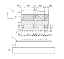
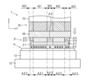
- FIG. 1 is a diagram showing the overall configuration of a mounting apparatus according to first and second embodiments of the present invention.
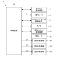
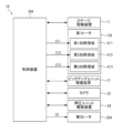
- FIG. 2 is a control block diagram of the mounting apparatus according to the first embodiment of the present invention.
- FIG. 3 is a plan view of an integrated package mounted on a substrate by the mounting apparatus of the present invention.
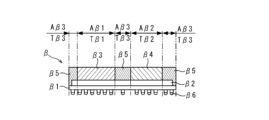
- FIG. 4 is a cross-sectional view taken along the line IV-IV in FIG.
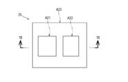
- FIG. 5 is a plan view of the second heater according to the first embodiment of the present invention.
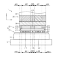
- 6 is a cross-sectional view taken along line VI-VI in FIG. 5 and line IV-IV in FIG.
- FIG. 7 is a partial cross-sectional view of the jig.
- FIG. 1 is a diagram showing the overall configuration of a mounting apparatus according to first and second embodiments of the present invention.
- FIG. 2 is a control block diagram of the mounting apparatus according to the first embodiment of the present invention.
- FIG. 3 is a plan view of an integrated package mounted on a substrate by the
- FIG. 8 is a partial cross-sectional view of the mounting device and the jig in a state in which the jig is held by the mounting device according to the first embodiment of the present invention.
- FIG. 9 is a partial cross-sectional view of the mounting device and the integrated package in a state in which the mounting device holds the substrate and the integrated package according to the first embodiment of the present invention.
- FIG. 10 is a partial cross-sectional view of the mounting device and the integrated package in a state in which the integrated package has been placed on a substrate by the mounting device according to the first embodiment of the present invention.
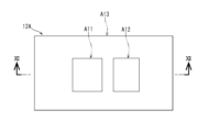
- FIG. 11 is a plan view of a first heating unit in the second embodiment of the present invention.
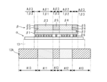
- FIG. 12 is a cross-sectional view taken along line XII-XII in FIG.
- FIG. 11 is a cross-sectional view of the substrate and the integrated package.
- FIG. 13 is a control block diagram of a mounting apparatus according to the second embodiment of the present invention.
- FIG. 14 is a partial cross-sectional view of a mounting device and a jig in a state in which the jig is held by the mounting device according to the second embodiment of the present invention.
- FIG. 15 is a partial cross-sectional view of a mounting apparatus according to the third embodiment of the present invention in a state in which an integrated package is placed on a substrate by the mounting apparatus.
- FIG. 16 is a control block diagram of a mounting apparatus according to the third embodiment of the present invention.
- the mounting device according to the present invention will be described with reference to the drawings.
- the same parts are given the same reference numerals, and the description of the same parts will not be repeated.
- the dimensions of the components in each drawing do not faithfully represent the actual dimensions of the components and the dimensional ratios of each component.
- the X and Y directions are assumed to be directions on a horizontal plane.
- the Y direction is a direction perpendicular to the X direction.
- the Z direction is a direction perpendicular to the X and Y directions.
- the Z direction is defined as the vertical direction.
- this definition of the direction is not intended to limit the orientation of the positioning device in each embodiment when in use.
- fixing includes not only cases where members are directly fixed, etc. to each other, but also cases where they are fixed, etc. via other members.
- fixing, etc. includes the meaning of direct and indirect fixing, etc. between members.
- FIG. 1 is an overall configuration diagram of a mounting device 1 according to the first embodiment of the present invention and a mounting device 1A according to a second embodiment of the present invention.
- Fig. 2 is a control block diagram of the mounting device 1.
- the mounting device 1 mounts an integrated package ⁇ on a substrate ⁇ .
- the mounting device 1 is provided in a manufacturing device such as a semiconductor manufacturing device (not shown).
- the mounting device 1 has a stage unit 10, a pickup unit 20, and a control device 30 (see FIG. 2).
- the stage unit 10 is a movable stage that positions the substrate ⁇ at any position on the XY plane.
- the stage unit 10 is supported by a frame (not shown).
- the stage unit 10 is positioned with the stage mounting surface 10a facing the Z direction.
- the stage unit 10 has a stage driving device 11.
- the stage unit 10 is configured so that the stage mounting surface 10a can be moved to any position on the XY plane by the stage driving device 11.
- the stage unit 10 supports a first heater 12, which is a first heating section, and a first attachment 13.
- the first heater 12 heats the substrate ⁇ via the first attachment 13.
- the first heater 12 is, for example, a pulse heater having a ceramic housing.
- the first heater 12 includes a laser heating type heater that heats with a laser, an induction heating type heater, and the like.
- the first heater 12 may be a heating device that can heat the first attachment.
- the first heater 12 is configured to generate heat at a first heat generation amount C1, which is a preset heat generation amount per unit time and unit area.
- the first heater 12 is fixed to the stage mounting surface 10a of the stage unit 10.
- the first heater 12 is disposed with the heating surface facing the Z direction.
- the first heater 12 is configured to be movable integrally with the stage unit 10.
- the heat generation amount per unit time and unit area on the heating surface of the first heater 12 is equal at all positions. In other words, the first heater 12 heats the entire heating surface equally.
- the first attachment 13 holds the substrate ⁇ .
- the first attachment 13 is, for example, a rectangular parallelepiped made of metal.
- the first attachment 13 is fixed to the heating surface of the first heater 12 in a detachable state.
- the first attachment 13 is arranged with the first attachment holding surface 13a that holds the substrate ⁇ facing the Z direction.
- the first attachment 13 has a plurality of suction holes (not shown) in the first attachment holding surface 13a.
- the first attachment 13 is configured so that the suction holes can be sucked by a suction device (not shown).
- the first attachment 13 is configured so that the substrate ⁇ can be sucked and held on the first attachment holding surface 13a by the suction force generated in the suction holes.
- the first attachment 13 is configured so that it can move integrally with the first heater 12 by the stage unit 10.
- the first attachment 13 is also heated by the first heater 12.
- the pickup unit 20 is a unit that positions the integrated package ⁇ at any position on the XY plane.
- the pickup unit 20 is supported by a frame (not shown).
- the pickup unit 20 is positioned with the pickup unit mounting surface 20a facing the first attachment 13.
- the pickup unit 20 has a pickup unit drive device 21.
- the pickup unit 20 is configured so that it can be moved to any position on the XY plane by the pickup unit drive device 21.
- the pickup unit 20 is provided with a camera 22 that measures the positions of the substrate ⁇ and the integrated package ⁇ .
- the pickup unit 20 supports a pressing unit 23, a second heater 25 which is a second heating section, and a second attachment 26.
- the pressing unit 23, which is a pressing section, is a unit that moves the integrated package ⁇ in the Z direction.
- the pressing unit 23 is fixed to the pickup unit mounting surface 20a.
- the pressing unit 23 is arranged so that the pressing unit mounting surface 23a faces the first attachment 13.
- the pressing unit 23 is configured so that the pressing unit mounting surface 23a can be moved relatively to any position in the Z direction toward the stage unit 10 by the pressing unit driving device 24.
- the pressing unit 23 is also configured so that the pressing unit mounting surface 23a can be pressed against an object with a predetermined force by the pressing unit driving device 24.
- the pressing unit 23 is also configured so that it can move integrally with the pickup unit 20. In other words, the pressing unit 23 is configured so that it can place the integrated package ⁇ at any position on the substrate ⁇ and press it.
- the second heater 25 heats the integrated package ⁇ via the second attachment 26.
- the second heater 25 is, for example, a constant heater having a ceramic housing.
- the second heater 25 is fixed to the pressing unit mounting surface 23a.
- the second heater 25 is arranged with its heating surface facing the first attachment 13.
- the second heater 25 is configured to be movable integrally with the pressing unit 23.
- the second heater 25 has multiple heating regions.
- the second attachment 26 holds the integrated package ⁇ .
- the second attachment 26 is configured as a rectangular parallelepiped made of, for example, an inorganic material such as ceramics, a metal, or the like.
- the second attachment 26 is fixed to the mounting surface of the pressing unit 23 in a detachable state.
- the second attachment 26 is arranged with the second attachment holding surface 26a that holds the integrated package ⁇ facing the first attachment 13.
- the second attachment 26 has a shape that overlaps with the entire integrated package ⁇ arranged on the substrate ⁇ when viewed in the pressing direction of the pressing unit 23 when the substrate ⁇ is held in a predetermined position on the first attachment 13.
- the second attachment 26 has a suction hole (not shown) on the second attachment holding surface 26a.
- the second attachment 26 is configured to be able to suck the suction hole by a suction device (not shown).
- the second attachment 26 is configured to be able to suck and hold the integrated package ⁇ on the second attachment holding surface 26a by the suction force generated in the suction hole.
- the second attachment 26 is configured to be movable together with the pickup unit 20 and the pressing unit 23.
- the control device 30 controls the stage drive device 11, the first heater 12, the pickup unit drive device 21, the camera 22, the pressing unit drive device 24, the second heater 25, and a suction pump (not shown).
- the control device 30 is actually a CPU, ROM, RAM, HDD, etc. connected via a bus. Alternatively, the control device 30 may be configured as a one-chip LSI, etc.
- the control device 30 stores various programs and data for controlling the operation of the stage drive device 11, the first heater 12, the pickup unit drive device 21, the pressing unit drive device 24, the second heater 25, and a suction pump (not shown).
- the control device 30 is electrically connected to the X-direction actuator and the Y-direction actuator of the stage driving device 11.
- the control device 30 is electrically connected to the X-direction actuator and the Y-direction actuator of the pickup unit driving device 21.
- the control device 30 is electrically connected to the Z-direction actuator of the pressing unit driving device 24.
- the control device 30 is electrically connected to the camera 22.
- the control device 30 is electrically connected to the first heater 12 and the second heater 25.
- the control device 30 is also electrically connected to the camera 22.
- the control device 30 is electrically connected to the X-direction scale and the Y-direction scale included in the stage driving device 11 and the pickup unit driving device 21.
- the control device 30 is electrically connected to the Z-direction scale included in the pressing unit driving device 24.
- the control device 30 is configured to be capable of outputting a position control signal to the stage driving device 11 for positioning the first attachment 13 (see FIG. 1) mounted on the stage unit 10 at a target position.
- the control device 30 is configured to be capable of outputting a position control signal to the pickup unit driving device 21 and the pressing unit driving device 24 for positioning the second attachment 26 mounted on the pressing unit 23 at a target position.
- the control device 30 is configured to be capable of outputting a heat generation amount control signal to the first heater 12 to cause it to generate heat at a first heat generation amount C1.
- the control device 30 is configured to be capable of outputting a heat generation amount control signal to cause the multiple heating regions of the second heater 25 to generate heat at a predetermined heat generation amount.
- the control device 30 is configured to be capable of outputting a control signal to the camera 22 for capturing images of the substrate ⁇ and the integrated package ⁇ .
- the control device 30 is configured to be capable of outputting a suction control signal to a suction pump (not shown).
- the control device 30 can obtain the X and Y coordinates of the substrate ⁇ and the integrated package ⁇ using the camera 22.
- the control device 30 can obtain the X and Y coordinates of the first attachment 13 and the second attachment 26 using the X-direction scale and the Y-direction scale.
- the control device 30 can obtain the Z coordinate of the second attachment 26 using the Z-direction scale.
- the mounting device 1 configured in this manner holds the substrate ⁇ by suction when the substrate ⁇ is loaded onto the first attachment 13 of the stage unit 10 from an external transport device.
- the mounting device 1 holds the integrated package ⁇ by suction using the second attachment of the pickup unit 20.
- the mounting device 1 adjusts the position of the substrate ⁇ in the X and Y directions using the stage driving device 11, and adjusts the position of the integrated package ⁇ in the X and Y directions using the pickup unit driving device 21.
- the mounting device 1 adjusts the position of the integrated package ⁇ in the Z direction using the pressing unit driving device 24, and places the integrated package ⁇ in a predetermined position on the substrate ⁇ .
- the mounting device 1 presses the integrated package ⁇ , which is placed at a predetermined position on the substrate ⁇ , toward the substrate ⁇ using the pressing unit driving device 24. At the same time, the mounting device 1 heats the substrate ⁇ via the first attachment 13 using the first heater 12. The mounting device 1 heats the integrated package ⁇ via the second attachment 26 using the second heater 25. The heat transmitted to the substrate ⁇ via the first attachment 13 and the heat transmitted to the integrated package ⁇ via the second attachment 26 melt the bumps ⁇ 6 (see Figure 4) of the integrated package ⁇ . In this way, the mounting device 1 connects the integrated package ⁇ to the predetermined position on the substrate ⁇ .
- Fig. 3 is a plan view of the integrated package ⁇ mounted on a substrate by the mounting apparatuses 1, 1A, and 1B.
- Fig. 4 is a cross-sectional view taken along the line IV-IV in Fig. 3.
- the integrated package ⁇ is an integrated package in which a first semiconductor chip ⁇ 3 and a second semiconductor chip ⁇ 4 are connected to a resin package substrate ⁇ 1 (see Figure 4) via a silicon interposer ⁇ 2 (see Figure 4).
- the integrated package ⁇ is molded with resin ⁇ 5.
- the surfaces of the first semiconductor chip ⁇ 3 and the second semiconductor chip ⁇ 4 opposite the silicon interposer ⁇ 2 are not covered with resin ⁇ 5.
- the package substrate ⁇ 1 has bumps ⁇ 6 including electrodes.
- the integrated package ⁇ has a first region A ⁇ 1 in which the package substrate ⁇ 1 (see FIG. 4), the silicon interposer ⁇ 2 (see FIG. 4), and the first semiconductor chip ⁇ 3 are stacked, a second region A ⁇ 2 in which the package substrate ⁇ 1, the silicon interposer ⁇ 2, and the second semiconductor chip ⁇ 4 are stacked, and a third region A ⁇ 3 (shaded portion) in which the package substrate ⁇ 1, the silicon interposer ⁇ 2, and the resin ⁇ 5 are stacked.
- the pressure direction thermal conductivity T ⁇ 1 of the first region A ⁇ 1 is the highest in the integrated package ⁇ .
- the bump ⁇ 6 located in the first region A ⁇ 1 is the most susceptible to heating and cooling (the least likely to store heat).
- the bump ⁇ 6 located in the first region A ⁇ 1 is the least susceptible to heating and cooling (the least likely to store heat). Therefore, unless heating is continued, the temperature of the first region A ⁇ 1 is likely to drop below the temperature required for mounting on the board ⁇ .
- the thermal conductivity T ⁇ 2 of the second region A ⁇ 2 in the pressing direction is the second highest in the integrated package ⁇ after the first region A ⁇ 1.
- the pressure direction thermal conductivity T ⁇ 3 of the third region A ⁇ 3 is the lowest in the integrated package ⁇ .
- the bump ⁇ 6 located in the third region A ⁇ 3 is the least likely to heat up and the least likely to cool down (easily accumulates heat).
- the bump ⁇ 6 located in the third region A ⁇ 3 is the most likely to heat up and the least likely to cool down (easily accumulates heat). Therefore, the third region A ⁇ 3 is likely to become higher than the above temperature if heating continues.
- Fig. 5 is a plan view of the second heater 25.
- Fig. 6 is a cross-sectional view taken along line VI-VI in Fig. 5 and a cross-sectional view taken along line IV-IV in Fig. 3.
- Fig. 7 is a partial cross-sectional view of the jig T.
- Fig. 8 is a partial cross-sectional view of the mounting device 1 and the jig T in a state in which the jig T is held by the mounting device 1.
- an integrated package ⁇ is disposed at a predetermined position on the substrate ⁇ .
- the second heater 25 has a shape that overlaps at least a portion of the integrated package ⁇ arranged on the substrate ⁇ when viewed in the pressing direction of the pressing unit 23 while the substrate ⁇ is held at a predetermined position on the first attachment 13.
- the second heater 25 overlaps the entire integrated package ⁇ when viewed in the pressing direction.
- the second heater 25 is configured to be able to receive the force applied to the integrated package ⁇ by the pressing unit 23.
- the second heater 25 has multiple heating regions.
- the second heater 25 has, as multiple heating regions, a first heating region A21, a second heating region A22, and a third heating region A23 based on the distribution of the thermal conductivity in the pressing direction of the integrated package ⁇ when viewed in the pressing direction.
- the first heating region A21, the second heating region A22, and the third heating region A23 are configured so that the heat generation amount per unit time and per unit area can be changed independently.
- the first heating region A21 generates heat at a first heating region heat generation amount C21, which is the heat generation amount per unit time and per unit area (see FIG. 2).
- the second heating region A22 generates heat at a second heating region heat generation amount C22, which is the heat generation amount per unit time and per unit area (see FIG. 2).
- the third heating region A23 generates heat at a third heating region heat generation amount C23, which is the heat generation amount per unit time and per unit area (see FIG. 2).
- the first heated area A21 overlaps with at least a portion of the first area A ⁇ 1 of the integrated package ⁇ when viewed in the pressing direction.
- the second heated area A22 overlaps with at least a portion of the second area A ⁇ 2 of the integrated package ⁇ when viewed in the pressing direction.
- the third heated area A23 overlaps with the third area A ⁇ 3 when viewed in the pressing direction.
- the first heated area A21 overlaps with the entire first area A ⁇ 1 when viewed in the pressing direction, and has approximately the same shape as the first area A ⁇ 1.
- the second heated area A22 overlaps with the entire second area A ⁇ 2 when viewed in the pressing direction, and has approximately the same shape as the second area A ⁇ 2.
- the third heated area A23 overlaps with the entire third area A ⁇ 3 when viewed in the pressing direction.
- the first heating area A21, the second heating area A22, and the third heating area A23 are electrically connected to the control device 30.
- the first heating area A21 is configured to generate heat, for example, at a first heating area heat generation amount C21, based on a heat generation control signal from the control device 30.
- the second heating area A22 is configured to generate heat, for example, at a second heating area heat generation amount C22, based on a heat generation control signal from the control device 30.
- the third heating area A23 is configured to generate heat, for example, at a third heating area heat generation amount C23, based on a heat generation control signal from the control device 30.
- the heat generation amount of the first heating area A21, the second heating area A22, and the third heating area A23 is determined by temperature measurement using a jig T.
- the jig T is pressed by the pressing unit 23 via the second attachment 26 while mounted on the first attachment 13 of the mounting device 1. Furthermore, the jig T is heated by the first heater 12, which generates heat with a first heat amount C1, and is also heated by the first heating area A21, the second heating area A22, and the third heating area A23 of the second heater 25 (see FIG. 8). At this time, the first heating area A21, the second heating area A22, and the third heating area A23 generate heat with a second heat amount C2.
- the heat from the first heater 12 transferred to the substrate ⁇ is transferred to the integrated package ⁇ at a rate proportional to the pressing direction thermal conductivity T ⁇ 1 of the first region A ⁇ 1 (see FIG. 7), the pressing direction thermal conductivity T ⁇ 2 of the second region A ⁇ 2 (see FIG. 7), and the pressing direction thermal conductivity T ⁇ 3 of the third region A ⁇ 3 (see FIG. 7).
- the portion of the substrate ⁇ of the jig T that overlaps with the first region A ⁇ 1, which has the highest pressing direction thermal conductivity T ⁇ 1, when viewed in the pressing direction, is most likely to transfer heat to the integrated package ⁇ .
- heat transferred to the portion of the substrate ⁇ that overlaps with the first region A ⁇ 1 when viewed in the pressing direction is most likely to escape from the substrate ⁇ to the integrated package ⁇ .
- the portion of the substrate ⁇ of the jig T that overlaps with the third region A ⁇ 3, which has the lowest pressing direction thermal conductivity T ⁇ 3, when viewed in the pressing direction, is least likely to transfer heat to the integrated package ⁇ .
- heat transferred to the portion of the substrate ⁇ that overlaps with the third region A ⁇ 3 is less likely to escape from the substrate ⁇ to the integrated package ⁇ .
- the heat from the first heater 12 transferred to the substrate ⁇ is transferred to the integrated package ⁇ at a rate proportional to the temperature difference between the first region A ⁇ 1 and the substrate ⁇ , the temperature difference between the second region A ⁇ 2 and the substrate ⁇ , and the temperature difference between the third region A ⁇ 3 and the substrate ⁇ .
- the portion of the substrate ⁇ of the jig T that overlaps with the first region A ⁇ 1 having the highest pressing direction thermal conductivity T ⁇ 1 when viewed in the pressing direction is less able to transfer heat to the integrated package ⁇ .
- the portion of the substrate ⁇ of the jig T that overlaps with the third region A ⁇ 3 having the lowest pressing direction thermal conductivity T ⁇ 3 when viewed in the pressing direction is more able to transfer heat to the integrated package ⁇ .
- the first heating area A21, the second heating area A22, and the third heating area A23 heat each part of the integrated package ⁇ to different temperatures, and an amount of heat corresponding to the temperature difference generated between the substrate ⁇ and each part of the integrated package ⁇ is transferred from the substrate ⁇ to the integrated package ⁇ .
- the first heating area heat generation amount C21, the second heating area heat generation amount C22, and the third heating area heat generation amount C23 in the second heater 25 are determined to be heat generation amounts that include the temperature of the first area A ⁇ 1 detected by the first jig temperature sensor ⁇ 1 of the jig T, the temperature of the second area A ⁇ 2 detected by the second jig temperature sensor ⁇ 2, and the temperature of the third area A ⁇ 3 detected by the third jig temperature sensor ⁇ 3 within a predetermined range.
- the portion of the substrate ⁇ overlapping the first region A ⁇ 1 which has the highest thermal conductivity in the pressing direction, is heated by the first heating region A21, which generates heat at a first heating region heat value C21 higher than the second heating value C2, thereby reducing the temperature difference between the substrate ⁇ and the integrated package ⁇ . Therefore, when viewed in the pressing direction, the temperature of the portion of the substrate ⁇ overlapping the first region A ⁇ 1 is likely to rise because the amount of heat transferred to the first region A ⁇ 1 is suppressed.
- the control device 30 is electrically connected to the jig T and can acquire the temperature of the first area A ⁇ 1 detected by the first jig temperature sensor ⁇ 1 of the jig T, the temperature of the second area A ⁇ 2 detected by the second jig temperature sensor ⁇ 2, and the temperature of the third area A ⁇ 3 detected by the third jig temperature sensor ⁇ 3.
- the temperature sensors that measure the temperature of each heating area may be disposed in the second attachment 26.
- the control device 30 heats the first heating area A21 of the second heater 25, the heat generation amount of which has been adjusted as the first adjusted heating area in the first temperature adjustment process, and the first heater 12 with the adjusted heat generation amount, while setting the heating area of the second heater 25, the heat generation amount of which has not been adjusted in the first temperature adjustment process, as the second adjusted heating area, and heats the jig T by the second adjusted heating area.
- the control device 30 heats the jig T, for example, by setting the second heating area A22 of the second heater 25 as the second adjusted heating area.
- the control device 30 heats the first heating area A21 of the second heater 25 with the heat generation amount adjusted in the first temperature adjustment step, and heats the second heating area A22 of the second heater 25 with the heat generation amount adjusted in the second temperature adjustment step, while heating the first heater 12. Furthermore, the control device 30 readjusts the heat generation amount of the first heating area A21 and the heat generation amount of the second heating area A22 of the second heater 25 so that the temperature of the first area A ⁇ 1 detected by the first fixture temperature sensor ⁇ 1 is within the target temperature range of the first area A ⁇ 1, and the temperature of the second area A ⁇ 2 detected by the second fixture temperature sensor ⁇ 2 is within the target temperature range of the second area A ⁇ 2.
- the control device 30 performs a first temperature adjustment process in which one of the heating regions is used as a first adjustment heating region to adjust the heat generation amount, and then performs a second adjustment process in which the other heating region, whose heat generation amount was not adjusted in the first temperature adjustment process, is used as a second adjustment heating region to adjust the heat generation amount. Furthermore, the control device 30 readjusts the heat generation amount of each heating region so that the temperature of the region heated by each adjustment heating region, whose heat generation amount was adjusted in the first and second temperature adjustment processes, falls within the target temperature range of each region. This makes it possible to adjust the heat generation amount of each heating region while taking into account the influence of the other heating regions.
- the mounting device 1 configured in this manner makes the temperature difference between the substrate ⁇ and the first region A ⁇ 1 smaller than in other regions, thereby suppressing the amount of heat transferred from the substrate ⁇ to the integrated package ⁇ .
- the mounting device 1 also makes the temperature difference between the substrate ⁇ and the third region A ⁇ 3 larger than in other regions, thereby increasing the amount of heat transferred from the substrate ⁇ to the integrated package ⁇ .
- the mounting device 1 adjusts the heat generation amounts of the first heating region A21, the second heating region A22, and the third heating region A23 based on the distribution of the pressure direction thermal conductivity of the integrated package ⁇ , thereby suppressing the variation in temperature distribution between the substrate ⁇ and the integrated package ⁇ and suppressing poor connection of the integrated package ⁇ to the substrate ⁇ .
- FIG. 9 is a partial cross-sectional view of the mounting device 1 and the integrated package ⁇ in a state in which the mounting device 1 holds the substrate ⁇ and the integrated package ⁇ .
- Figure 10 is a cross-sectional view of the mounting device 1 and the integrated package ⁇ in a state in which the integrated package ⁇ is placed on the substrate ⁇ in the first embodiment. Note that the mounting device 1 controls each part by a control signal from the control device 30.
- the mounting device 1 loads the substrate ⁇ onto the first attachment 13 by an external transport device (not shown).
- the mounting device 1 adsorbs and holds the substrate ⁇ via the first attachment 13.
- the substrate ⁇ is held at a predetermined position on the first attachment 13.
- the mounting device 1 sucks and holds the accumulated package ⁇ , which is in a predetermined waiting position, via the second attachment 26, by the pressing unit 23, which is moved by the pickup unit driving device 21.
- the accumulated package ⁇ is held in a predetermined position by the second attachment 26.
- the first heating area A21 of the second heater 25 holding the second attachment 26 overlaps with the first area A ⁇ 1 of the accumulated package ⁇ when viewed in the pressing direction.
- the second heating area A22 of the second heater 25 overlaps with the second area A ⁇ 2 of the accumulated package ⁇ when viewed in the pressing direction.
- the third heating area A23 of the second heater 25 overlaps with the third area A ⁇ 3 of the accumulated package ⁇ when viewed in the pressing direction.
- the mounting device 1 uses the pressing unit 23 to place the integrated package ⁇ on the substrate ⁇ mounted on the first attachment 13. At this time, the integrated package ⁇ is held by the second attachment 26 with the bumps ⁇ 6 of the integrated package ⁇ in contact with the electrodes on the substrate ⁇ .
- the mounting device 1 heats the first heater 12 with a first heating amount C1 to melt the bump ⁇ 6. At the same time, the mounting device 1 heats the first heating area A21 with a first heating area heating amount C21, the second heating area A22 with a second heating area heating amount C22, and the third heating area A23 with a third heating area heating amount C23 in the second heater 25.
- Heat is uniformly transferred from the heating surface of the first heater 12 to the substrate ⁇ via the first attachment 13. Heat is transferred from the first heating area A21, the second heating area A22, and the third heating area A23 to the integrated package ⁇ via the second attachment 26.
- the mounting device 1 presses the integrated package ⁇ toward the substrate ⁇ with a predetermined external force using the pressing unit 23.
- the temperature of the first heater 12 is higher than the maximum temperature of the second heater 25.
- the heat from the first heater 12 transferred to the portion overlapping with the first region A ⁇ 1 of the substrate ⁇ in the pressing direction is transferred to the first region A ⁇ 1 of the integrated package ⁇ based on the pressing direction thermal conductivity T ⁇ 1 of the first region A ⁇ 1 and the temperature difference between the first region A ⁇ 1 and the substrate ⁇ (see FIG. 6).
- the heat from the first heater 12 transferred to the portion overlapping with the second region A ⁇ 2 of the substrate ⁇ in the pressing direction is transferred to the second region A ⁇ 2 of the integrated package ⁇ based on the pressing direction thermal conductivity T ⁇ 2 of the second region A ⁇ 2 and the temperature difference between the second region A ⁇ 2 and the substrate ⁇ (see FIG. 6).
- the heat from the first heater 12 transferred to the portion overlapping with the third region A ⁇ 3 of the substrate ⁇ in the pressing direction is transferred to the third region A ⁇ 3 of the integrated package ⁇ based on the pressing direction thermal conductivity T ⁇ 3 of the third region A ⁇ 3 and the temperature difference between the third region A ⁇ 3 and the substrate ⁇ (see FIG. 6).
- Heat transferred to the portion of the substrate ⁇ that overlaps with the first region A ⁇ 1 in the pressing direction is transferred in the order of bump ⁇ 6 located in the first region A ⁇ 1 of the integrated package ⁇ , part of the package substrate ⁇ 1, part of the silicon interposer ⁇ 2, and the first semiconductor chip ⁇ 3 via electrodes of the substrate ⁇ , etc.
- Heat transferred to the portion of the substrate ⁇ that overlaps with the second region A ⁇ 2 in the pressing direction is transferred in the order of bump ⁇ 6 located in the second region A ⁇ 2 of the integrated package ⁇ , part of the package substrate ⁇ 1, part of the silicon interposer ⁇ 2, and the second semiconductor chip ⁇ 4 via electrodes of the substrate ⁇ , etc.
- Heat transferred to the portion of the substrate ⁇ that overlaps with the third region A ⁇ 3 in the pressing direction is transferred in the order of bump ⁇ 6 located in the third region A ⁇ 3 of the integrated package ⁇ , part of the package substrate ⁇ 1, part of the silicon interposer ⁇ 2, and the resin ⁇ 5 via electrodes of the substrate ⁇ , etc.
- Heat is transferred to the first region A ⁇ 1 of the integrated package ⁇ via the second attachment 26 from the first heated region A21, which is generating heat at a first heated region heat generation amount C21 (see Figure 2).
- the first region A ⁇ 1 is heated to a higher temperature than the second region A ⁇ 2 and the third region A ⁇ 3. In other words, the temperature difference between the first region A ⁇ 1 and the substrate ⁇ is the smallest.
- Heat is transferred to the second region A ⁇ 2 of the integrated package ⁇ via the second attachment 26 from the second heated region A22, which is generating heat at a second heated region heat generation amount C22 (see Figure 2).
- the second region A ⁇ 2 is heated to a lower temperature than the first region A ⁇ 1.
- the temperature difference between the second region A ⁇ 2 and the substrate ⁇ is the second smallest after the first region A ⁇ 1.
- Heat is transferred from the third heating area A23, which is generating heat at a third heating area heat generation amount C23 (see FIG. 2), to the third area A ⁇ 3 of the integrated package ⁇ via the second attachment 26.
- the third area A ⁇ 3 is heated to a lower temperature than the second area A ⁇ 2.
- the temperature difference between the third area A ⁇ 3 and the substrate ⁇ is the largest.
- the mounting device 1 adjusts the amount of heat transmitted from the substrate ⁇ to the integrated package ⁇ by adjusting the heat generated by the first heating region A21, the second heating region A22, and the third heating region A23. In other words, the mounting device 1 adjusts the ease of transmission of heat from the first heater 12 from the substrate ⁇ to the integrated package ⁇ by the second heater 25. This allows the temperature between the substrate ⁇ and the integrated package ⁇ to be maintained within a predetermined range.
- the integrated package ⁇ which is heated by the first heater 12 and the second heater 25 and pressed against the substrate ⁇ by the pressing unit 23, comes into contact with the electrodes of the substrate ⁇ with the bumps ⁇ 6 in a melted state.
- the mounting device 1 stops heating by the first heater 12 and the second heater 25. Furthermore, the mounting device 1 stops pressing by the pressing unit 23 a predetermined time after heating by the first heater 12 and the second heater 25 has stopped.
- the mounting device 1 heats the first heating area A21, the second heating area A22, and the third heating area A23, which are divided based on the first area A ⁇ 1, the second area A ⁇ 2, and the third area A ⁇ 3 of the integrated package ⁇ , at a temperature based on the thermal conductivity of the integrated package ⁇ in the pressing direction, so that it is possible to suppress changes in the temperature distribution of the substrate ⁇ due to the influence of not only the shape of the integrated package ⁇ but also the internal structure of the integrated package ⁇ .
- This makes it possible to suppress temperature variations when the integrated package ⁇ , which has a non-uniform thermal conductivity, is heated, and to suppress poor connection of the integrated package ⁇ to the substrate ⁇ .
- the mounting device 1 if the integrated package ⁇ is heated by the first heating area A21, the second heating area A22, and the third heating area A23 of the second heater 25, and the substrate ⁇ is not heated by the first heater 12, it is necessary to increase the temperature of the second heater 25 in order to heat the bump ⁇ 6 that is distant from the second heater 25.
- the second attachment 26 heated by the second heater 25 may experience a thermal shock inside the attachment due to an increase in the temperature of the first heating area A21, the second heating area A22, and the third heating area A23 of the second heater 25 and the temperature difference between the areas, which may cause distortion of the second attachment.
- the first heater 12 which is a constant heater that constantly heats the substrate ⁇
- the flux, resin adhesive, etc. applied to the electrodes of the substrate ⁇ may be altered by the heat.
- the substrate ⁇ is heated at a temperature at which the flux, resin adhesive, etc. applied to the substrate ⁇ is not altered, it takes time for the bumps ⁇ 6 to weld the substrate ⁇ and the integrated package ⁇ , reducing production efficiency.
- the first heater 12 which is a pulse heater with a forced cooling function, rapidly heats the substrate ⁇ to a predetermined temperature for a predetermined time and then rapidly cools it, thereby preventing deterioration of the flux, resin adhesive, etc. applied to the substrate ⁇ .
- the set temperature of the second heater 25 can be lowered and thermal shock of the second attachment can be prevented.
- FIG. 11 is a plan view of a first heater 12A.
- Fig. 12 is a cross-sectional view taken along line XII-XII in Fig. 11 and a cross-sectional view of a substrate ⁇ and an integrated package ⁇ .
- Fig. 13 is a control block diagram of the mounting device 1A.
- first heater 12A and second heater 25A are different from those of first heater 12 and second heater 25 of mounting device 1.
- the same components as those in embodiment 1 are given the same reference numerals and their explanation is omitted, and only the parts that differ from embodiment 1 are explained.
- the mounting apparatus 1A has a stage unit 10, a pickup unit 20, and a control device 30 (see FIG. 13).
- the stage unit 10 supports a first heater 12A, which is a first heating section, and a first attachment 13.
- the pickup unit 20 supports a pressing unit 23, a second heater 25A, and a second attachment 26.
- the first heater 12A which is the first heating section, heats the substrate ⁇ via the first attachment 13.
- the first heater 12A is, for example, a constant heater having a ceramic housing.
- the first heater 12A is fixed to the stage mounting surface 10a of the stage unit 10.
- the first heater 12A is arranged with its heating surface facing the Z direction.
- the first heater 12A is configured to be movable integrally with the stage unit 10.
- the first heater 12A has multiple heating regions.
- the second heater 25A which is the second heating section, heats the integrated package ⁇ via the second attachment 26.
- the second heater 25A is, for example, a constant heater having a ceramic housing.
- the second heater 25A is fixed to the pressing unit mounting surface 23a.
- the second heater 25A is arranged with its heating surface facing the first attachment 13.
- the second heater 25A is configured to be movable integrally with the pressing unit 23.
- the second heater 25 has multiple heating regions. The amount of heat generated per unit time and per unit area on the heating surface of the second heater 25A is equal at all positions. In other words, the second heater 25A heats the entire heating surface equally.
- control device 30A is configured to be capable of outputting a heat generation amount control signal to the second heater 25 to cause it to generate heat at a first heat generation amount C1.
- the control device 30A is configured to be capable of outputting a heat generation amount control signal to cause the multiple heating regions of the first heater 12A to generate heat at a predetermined heat generation amount.
- the first heating area A11, the second heating area A12, and the third heating area A13 of the first heater 12A will be described with reference to Fig. 12.
- the first heater 12A has a shape that overlaps at least a part of the integrated package ⁇ arranged on the substrate ⁇ when viewed in the pressing direction in a state in which the substrate ⁇ is held at a predetermined position on the first attachment 13. In this embodiment, the first heater 12A overlaps the entire integrated package ⁇ when viewed in the pressing direction.
- the first heater 12A is configured to be able to receive the force applied to the integrated package ⁇ by the pressing unit 23.
- the heating area of the first heater 12A is divided into a plurality of heating areas.
- the first heater 12A has a first heating area A11, a second heating area A12, and a third heating area A13 as a plurality of heating areas based on the distribution of the thermal conductivity in the pressing direction of the integrated package ⁇ when viewed in the pressing direction.
- the first heating area A11, the second heating area A12, and the third heating area A13 are configured so that the amount of heat generated per unit time and per unit area can be changed independently.
- the first heating area A11 generates heat at a first heating area heat generation amount C11 (see FIG. 13), which is the amount of heat generated per unit time and per unit area.
- the second heating area A12 generates heat at a second heating area heat generation amount C12 (see FIG. 13), which is the amount of heat generated per unit time and per unit area.
- the third heating area A13 generates heat at a third heating area heat generation amount C13 (see FIG. 13), which is the amount of heat generated per unit time and per unit area.
- the first heated area A11 overlaps with at least a portion of the first area A ⁇ 1 of the integrated package ⁇ when viewed in the pressing direction.
- the second heated area A12 overlaps with at least a portion of the second area A ⁇ 2 of the integrated package ⁇ when viewed in the pressing direction.
- the third heated area A13 overlaps with the third area A ⁇ 3 when viewed in the pressing direction.
- the first heated area A11 overlaps with the entire first area A ⁇ 1 of the integrated package ⁇ when viewed in the pressing direction, and has approximately the same shape as the first area A ⁇ 1.
- the second heated area A12 overlaps with the entire second area A ⁇ 2 of the integrated package ⁇ when viewed in the pressing direction, and has approximately the same shape as the second area A ⁇ 2.
- the third heated area A13 overlaps with the entire third area A ⁇ 3 of the integrated package ⁇ when viewed in the pressing direction.
- the first heating area A21, the second heating area A12, and the third heating area A13 are electrically connected to the control device 30A.
- the first heating area A11 is configured to generate heat, for example, at a first heating area heat generation amount C11, based on a heat generation control signal from the control device 30.
- the second heating area A12 is configured to generate heat, for example, at a second heating area heat generation amount C12, based on a heat generation control signal from the control device 30A.
- the third heating area A13 is configured to generate heat, for example, at a third heating area heat generation amount C13, based on a heat generation control signal from the control device 30A.
- FIG. 14 is a partial cross-sectional view of the mounting device 1A and the jig T in a state in which the jig T is held by the mounting device 1A in embodiment 2 of the present invention.
- the heat amounts of the first heating area A11, the second heating area A12, and the third heating area A13 are determined by temperature measurement using the jig T. Note that the minimum temperature of the first heater 12A is higher than the temperature of the second heater 25A.
- the first heating area A11, the second heating area A12, and the third heating area A13 heat each portion of the substrate ⁇ to different temperatures, thereby adjusting the amount of heat transferred from the substrate ⁇ to the integrated package ⁇ .
- the first heating area heat generation amount C11, the second heating area heat generation amount C12, and the third heating area heat generation amount C13 of the first heater 12A are determined to be heat generation amounts such that the temperature of the first area A ⁇ 1 detected by the first jig temperature sensor ⁇ 1 of the jig T, the temperature of the second area A ⁇ 2 detected by the second jig temperature sensor ⁇ 2, and the temperature of the third area A ⁇ 3 detected by the third jig temperature sensor ⁇ 3 are within a predetermined range.
- the jig T is pressed by the pressing unit 23 via the second attachment 26 while mounted on the first attachment 13 of the mounting device 1. Furthermore, the jig T is heated by the second heater 25, which generates heat with a second heat amount C2 (see FIG. 13), and is also heated by the first heating area A11, the second heating area A12, and the third heating area A13 of the first heater 12A. At this time, the first heating area A11, the second heating area A12, and the third heating area A13 generate heat with a first heat amount C1.
- the amount of heat transferred from the portion of the substrate ⁇ heated by the first heating area A11 to the first area A ⁇ 1 is greater than the amount of heat transferred from the portion of the substrate ⁇ heated by the other heating areas to the integrated package ⁇ .
- the amount of heat transferred from the portion of the substrate ⁇ heated by the third heating area A13 to the third area A ⁇ 3 is less than the amount of heat transferred from the portion of the substrate ⁇ heated by the other heating areas to the integrated package ⁇ .
- the amount of heat transferred from the first heating area A11 to the portion of the substrate ⁇ overlapping with the first area A ⁇ 1, which has the highest thermal conductivity in the pressing direction, increases as a result of being heated by the first heating area A11, which generates heat at a first heating area heat generation amount C11 (see FIG. 13) higher than the first heat generation amount C1. Therefore, the temperature of the portion of the substrate ⁇ overlapping with the first area A ⁇ 1 in the pressing direction is likely to rise because the difference between the amount of heat transferred from the substrate ⁇ to the integrated package ⁇ and the amount of heat transferred from the first heating area A11 to the substrate ⁇ becomes large.
- the amount of heat transferred from the third heating area A13 to the portion of the substrate ⁇ overlapping with the third area A ⁇ 3, which has the lowest thermal conductivity in the pressing direction decreases as a result of being heated by the third heating area A13, which generates heat at a third heating area heat generation amount C13 (see FIG. 13) lower than the first heat generation amount C1. Therefore, the temperature of the portion of the substrate ⁇ that overlaps with the third region A ⁇ 3 in the pressing direction is less likely to rise because the difference between the amount of heat transferred from the substrate ⁇ to the integrated package ⁇ and the amount of heat transferred from the third heating region A13 to the substrate ⁇ is small. This allows the first heating region A11, the second heating region A12, and the third heating region A13 to adjust the temperature between the substrate ⁇ and the integrated package ⁇ to within a predetermined range.
- the mounting device 1A configured in this manner increases the balance between the amount of heat transferred from the first heating region A11 to the portion of the substrate ⁇ overlapping with the first region A ⁇ 1 in the pressing direction and the amount of heat transferred from the substrate ⁇ to the first region A ⁇ 1.
- the mounting device 1 also decreases the balance between the amount of heat transferred from the third heating region A13 to the portion of the substrate ⁇ overlapping with the third region A ⁇ 3 in the pressing direction and the amount of heat transferred from the substrate ⁇ to the third region A ⁇ 3.
- the mounting device 1 adjusts the amounts of heat generated in the first heating region A21, the second heating region A22, and the third heating region A23 based on the distribution of the thermal conductivity in the pressing direction of the integrated package ⁇ , thereby suppressing the variation in the temperature distribution between the substrate ⁇ and the integrated package ⁇ and suppressing poor connection of the integrated package ⁇ to the substrate ⁇ .
- FIG. 15 is a partial cross-sectional view of the mounting device 1B in a state in which an integrated package ⁇ is placed on a substrate ⁇ by the mounting device 1B according to the third embodiment of the present invention.
- Fig. 16 is a control block diagram of the mounting device 1B.
- the mounting device 1B differs from the mounting device 1 in that the first attachment 13B has a first temperature sensor 27a, a second temperature sensor 27b, and a third temperature sensor 27c.
- the mounting apparatus 1B has a stage unit 10, a pickup unit 20, and a control device 30B (see FIG. 16).
- the stage unit 10 supports the first heater 12, which is the first heating section, and the first attachment 13B.
- the first attachment 13B has a first temperature sensor 27a, a second temperature sensor 27b, and a third temperature sensor 27c.
- the first temperature sensor 27a is positioned so as to overlap with a first region A ⁇ 1 of the integrated package ⁇ arranged on the substrate ⁇ held at a predetermined position on the first attachment 13B.
- the second temperature sensor 27b is positioned so as to overlap with a second region A ⁇ 2 of the integrated package ⁇ arranged on the substrate ⁇ .
- the third temperature sensor 27c is positioned so as to overlap with a third region A ⁇ 3 of the integrated package ⁇ arranged on the substrate ⁇ .
- the first temperature sensor 27a can measure the temperature of the portion of the substrate ⁇ that overlaps with the first region A ⁇ 1 when viewed in the pressing direction.
- the second temperature sensor 27b can measure the temperature of the portion of the substrate ⁇ that overlaps with the second region A ⁇ 2 when viewed in the pressing direction.
- the third temperature sensor 27c can measure the temperature of the portion of the substrate ⁇ that overlaps with the third region A ⁇ 3 when viewed in the pressing direction.
- control device 30B stores various programs and data for controlling the operation of the second heater 25 based on the temperatures detected by the first temperature sensor 27a, the second temperature sensor 27b, and the third temperature sensor 27c.
- the control device 30B is electrically connected to the first temperature sensor 27a, the second temperature sensor 27b, and the third temperature sensor 27c.
- the control device 30B is configured to be capable of outputting a temperature control signal to the first heating area A21 based on the temperature detected by the first temperature sensor 27a.
- the control device 30B is configured to be capable of outputting a temperature control signal to the second heating area A22 based on the temperature detected by the second temperature sensor 27b.
- the control device 30B is configured to be capable of outputting a temperature control signal to the third heating area A23 based on the temperature detected by the third heating area A23.
- the mounting device 1B can set the first heating area heat generation amount C21, the second heating area heat generation amount C22, and the third heating area heat generation amount C23 based on the temperatures detected by the first temperature sensor 27a, the second temperature sensor 27b, and the third temperature sensor 27c (see FIG. 16), instead of the first jig temperature sensor ⁇ 1 (see FIG. 7), the second jig temperature sensor ⁇ 2 (see FIG. 7), and the third jig temperature sensor ⁇ 3 (see FIG. 7) of the jig T.
- the mounting device 1B can adjust the amount of heat generated in the first heating area A21, the second heating area A22, and the third heating area A23 based on the temperatures detected by the first temperature sensor 27a, the second temperature sensor 27b, and the third temperature sensor 27c.
- the mounting device 1B can adjust the amount of heat generated in at least one of the first heating area A21, the second heating area A22, and the third heating area A23 to bring the detected temperature of the second temperature sensor 27b and the third temperature sensor 27c into the predetermined range. This can suppress temperature variations when an integrated package with non-uniform thermal conductivity is heated, and can suppress poor connection of the integrated package to the substrate.
- the mounting device 1 uniformly heats the first attachment 13 by the first heater 12, which is the first heating section, and heats the second attachment 26 with different heat amounts for each area by the first heating area A21, the second heating area A22, and the third heating area A23 of the second heater 25, which is the second heating section. Also, in the above-mentioned embodiment 2, the mounting device 1A heats the first attachment 13 with different heat amounts for each area by the first heating area A11, the second heating area A12, and the third heating area A13 of the first heater 12, which is the first heating section, and heats the second attachment 26 uniformly by the second heater 25, which is the second heating section.
- first heating section and the second heating section may each have a configuration having a plurality of heating areas.
- the mounting device configured in this manner can heat the first attachment 13 with different amounts of heat for each region by the first heating section, and can heat the second attachment 26 with different amounts of heat for each region by the second heating section.
- the first heating area A11 and the first heating area A21 have substantially the same shape as the first area A ⁇ 1.
- the second heating area A12 and the second heating area A22 have substantially the same shape as the second area A ⁇ 2.
- the third heating area A13 and the third heating area A23 have substantially the same shape as the third area A ⁇ 3.
- each heating area may have any shape that can heat the corresponding area.
- the mounting devices 1, 1A, and 1B press the substrate ⁇ and integrated package ⁇ mounted on the stage unit 10 using a pressing unit 23 that moves relatively toward the stage unit 10.
- the mounting device may be configured to press the substrate ⁇ and integrated package ⁇ by moving the stage unit on which the substrate ⁇ and integrated package ⁇ are mounted toward the pressing unit.
- the mounting devices 1, 1A, and 1B position the integrated package ⁇ relative to the substrate ⁇ using the pickup unit 20.
- the mounting devices may also be configured to position the substrate ⁇ relative to the integrated package ⁇ using a stage.
- the mounting devices 1, 1A, and 1B pick up the integrated package ⁇ using the pickup unit 20.
- the mounting devices may be configured to pick up the integrated package ⁇ using an external pickup unit and position it relative to the substrate ⁇ .
- the mounting devices 1, 1A, and 1B hold the substrate ⁇ with the first attachment 13 and hold the integrated package ⁇ with the second attachment.
- the mounting devices may be configured to hold the integrated package ⁇ with the first attachment and hold the substrate ⁇ with the second attachment.
- the mounting devices 1, 1A, and 1B heat the first attachment 13 with the first heater 12, which is a pulse heater, and heat the second attachment 26 with the second heater 25.
- the mounting device may be configured to heat the first attachment and the second attachment with a constant heater.
Landscapes
- Engineering & Computer Science (AREA)
- Manufacturing & Machinery (AREA)
- Microelectronics & Electronic Packaging (AREA)
- Wire Bonding (AREA)
- Die Bonding (AREA)
- Electric Connection Of Electric Components To Printed Circuits (AREA)
Abstract
熱伝導率が不均一な集積パッケージを加熱した際の温度のばらつきを抑制し、基板に対する前記集積パッケージの接続不良を抑制することができる実装装置を提供する。 具体的には、ステージと、前記基板及び前記集積パッケージを押圧する押圧部と、前記ステージに支持され、前記基板及び前記集積パッケージのいずれか一方に接触する第1アタッチメントと、前記押圧部に支持され、前記基板及び前記集積パッケージのいずれか他方に接触する第2アタッチメントと、前記第1アタッチメントを加熱する第1加熱部と、前記第2アタッチメントを加熱する第2加熱部と、を有する。前記第1加熱部及び前記第2加熱部の少なくとも一方は、前記集積パッケージの熱伝導率である押圧方向熱伝導率の分布に基づいた複数の加熱領域を有する。前記複数の加熱領域は、それぞれ異なる単位時間当たり且つ単位面積当たりの発熱量で発熱可能に構成される。
Description
本発明は基板に集積パッケージを実装する実装装置及び前記実装装置の調整方法に関する。
基板に半導体チップを実装する実装装置が知られている。前記実装装置は、ステージ上基板の所定位置に半導体チップを配置し、前記半導体チップのバンプを熱によって溶融させた状態で前記半導体チップを前記基板に押し付けることにより前記半導体チップを前記基板に接続させる。
このような実装装置において、前記半導体チップを前記基板に接続する際に加熱される前記半導体チップの温度分布が不均一である場合、前記半導体チップのバンプは、溶融状態にばらつきが生じる。この結果、前記半導体チップは、前記基板に対して接続不良が生じたり、前記半導体チップと前記基板とのギャップが不均一になったりして、正常に作動しない場合がある。そこで、前記基板と前記半導体チップとの接続不良、前記基板と前記半導体チップとのギャップの不均一等を抑制する実装装置が知られている。
特許文献1に記載の実装装置(半導体製造装置)は、前記基板に前記半導体チップを搭載するボンディングヘッドと、前記ボンディングヘッドに設けられ、前記半導体チップを吸引するアタッチメントと、前記アタッチメントを加熱する加熱部を有している。前記加熱部は、第1加熱エリアと前記第1加熱エリア水平方向に囲む第2加熱エリアとを有する。前記実装装置は、前記第1加熱エリアと前記第2加熱エリアとの温度を独立して制御することにより、前記半導体チップの温度分布を均一にしている。
特許文献1に記載の実装装置は、前記半導体チップの中心部分に比べて放熱によって温度が低下し易い前記半導体チップの周辺部分を加熱する第2加熱エリアの加熱温度を、前記半導体チップの中心部分を加熱する第1加熱エリアの加熱温度よりも高く設定することによって前記半導体チップの温度分布を均一にしている。しかしながら、複数の異なる半導体チップを樹脂によってモールディングした集積パッケージは、集積パッケージの中で熱伝導率が高い前記半導体チップの集積部分と前記半導体チップの集積部分よりも熱伝導率が低い樹脂部分とが不均一に位置している。つまり、前記集積パッケージは、単一の半導体チップに比べて、熱伝導率の分布が複雑になっている。よって、特許文献1に記載の実装装置では、前記基板と前記集積パッケージとの接続不良、前記基板と前記集積パッケージとのギャップの不均一等を抑制するための均一な加熱が難しい場合があった。
本発明の目的は、熱伝導率が不均一な集積パッケージを加熱した際の温度のばらつきを抑制し、基板に対する前記集積パッケージの接続不良を抑制することができる実装装置及びその調整方法の提供を目的とする。
本発明者は、熱伝導率が不均一な集積パッケージを加熱した際の温度のばらつきを抑制し、基板に対する前記集積パッケージの接続不良を抑制することができる実装装置の構成について検討した。鋭意検討の結果、本発明者は、以下のような構成に想到した。
本発明の実施形態に係る実装装置は、複数の半導体チップが集積され且つモールドされた集積パッケージ及び前記集積パッケージが実装される基板のうち少なくとも1つが搭載されるステージと、前記ステージと対向するように配置され、前記ステージに向かって相対的に移動し且つ前記基板及び前記集積パッケージを押圧する押圧部と、前記ステージに支持され、前記基板及び前記集積パッケージのいずれか一方に前記押圧部の移動方向から接触する第1アタッチメントと、前記押圧部に支持され、前記基板及び前記集積パッケージのいずれか他方に前記押圧部の移動方向から接触する第2アタッチメントと、前記ステージに支持され、前記第1アタッチメントを加熱する第1加熱部と、前記押圧部に支持され、前記第2アタッチメントを加熱する第2加熱部と、を有する。
前記第1加熱部及び前記第2加熱部の少なくとも一方は、前記押圧部の押圧方向における前記集積パッケージの熱伝導率である押圧方向熱伝導率の分布に基づいた複数の加熱領域を有する。前記複数の加熱領域は、それぞれ異なる単位時間当たり且つ単位面積当たりの発熱量で発熱可能に構成される。
上述の構成では、前記第1加熱部及び前記第2加熱部の少なくとも一方は、前記集積パッケージの押圧方向熱伝導率毎の分布に基づいた複数の加熱領域を有する。よって、前記第1加熱部及び前記第2加熱部の少なくとも一方は、前記集積パッケージの押圧方向熱伝導率に基づいた熱量によって前記集積パッケージを加熱する。前記実装装置は、前記押圧方向熱伝導率と、前記基板と前記集積パッケージとの温度差とによって定まる前記基板から前記集積パッケージに伝わる熱量を、複数の加熱領域による加熱によって調整する。これにより、熱伝導率が不均一な集積パッケージを均一に加熱した際の温度のばらつきを抑制し、基板に対する前記集積パッケージの接続不良を抑制することができる。
他の観点によれば、本発明の実装装置は、以下の構成を含むことが好ましい。前記複数の加熱領域は、前記押圧方向に見て、前記集積パッケージにおいて、異なる所定範囲の押圧方向熱伝導率を有する部分毎にそれぞれ重なる。
上述の構成では、前記複数の加熱領域は、前記集積パッケージの押圧方向熱伝導率が所定の範囲に含まれる部分を1つの領域とした押圧方向熱伝導率の領域に対応するように構成されている。よって、前記第1加熱部及び前記第2加熱部の少なくとも一方は、前記集積パッケージの押圧方向熱伝導率の領域毎に熱量を加えることにより押圧方向熱伝導率の領域毎の温度の調整に適切な熱量を伝えることができる。これにより、熱伝導率が不均一な集積パッケージを均一に加熱した際の温度のばらつきを抑制し、基板に対する前記集積パッケージの接続不良を抑制することができる。
他の観点によれば、本発明の実装装置は、以下の構成を含むことが好ましい。前記複数の加熱領域は、前記押圧方向に見て重なる前記集積パッケージの前記押圧方向熱伝導率の大きさに比例した発熱量で発熱するように構成される。
上述の構成では、前記加熱領域は、前記基板及び前記集積パッケージの少なくとも一方に接触する場合、前記集積パッケージの押圧方向熱伝導率が他の部分の押圧方向熱伝導率と比べて高い部分と重なる部分の前記加熱領域の発熱量を、前記他の部分と重なる加熱領域の発熱量よりも高くする。これにより、実装装置は、前記他の部分に比べて前記基板から前記集積パッケージに熱が伝わりやすい部分を前記他の部分よりも高い熱量で加熱することにより前記基板の温度低下を抑制することができる。また、前記加熱領域は、前記集積パッケージの押圧方向熱伝導率が他の部分よりも低い部分と重なる部分の前記押圧方向熱伝導率を前記他の部分と重なる加熱領域の発熱量よりも低くする。これにより、実装装置は、前記他の部分に比べて前記基板から前記集積パッケージに熱が伝わりにくい部分を前記他の部分よりも低い熱量で加熱することにより前記基板の温度上昇を抑制することができる。これにより、熱伝導率が不均一な集積パッケージを均一に加熱した際の温度のばらつきを抑制し、基板に対する前記集積パッケージの接続不良を抑制することができる。
他の観点によれば、本発明の実装装置は、以下の構成を含むことが好ましい。前記第1加熱部は、所定の単位時間当たり且つ単位面積当たりの発熱量で発熱する単一の加熱領域を有し、前記第1アタッチメントを介して、均一の熱量で発熱する単一の加熱領域によって前記基板を加熱する。前記第2加熱部は、前記複数の加熱領域を有し、前記第2アタッチメントを介して、前記集積パッケージの押圧方向熱伝導率の分布に基づいた異なる熱量で発熱する前記複数の加熱領域によって前記集積パッケージを加熱する。
上述の構成では、前記第1加熱部によって均一に加熱された前記基板から熱が伝わる前記集積パッケージを押圧方向熱伝導率の分布に基づいて前記第2加熱部の複数の加熱領域によって加熱する。前記実装装置は、集積パッケージを押圧方向熱伝導率が所定範囲の領域毎に押圧方向熱伝導率に基づいた熱量で加熱することにより、前記基板から前記集積パッケージに伝わる熱量を調整することができる。これにより、熱伝導率が不均一な集積パッケージを加熱した際の温度のばらつきを抑制し、基板に対する前記集積パッケージの接続不良を抑制することができる。
他の観点によれば、本発明の実装装置は、以下の構成を含むことが好ましい。前記第2加熱部を制御する制御部を有する。前記第1アタッチメントは、押圧方向に見て、前記複数の加熱領域と重なる位置に温度センサをそれぞれ有する。前記制御部は、前記温度センサによって検出される温度が所定範囲の温度になるように、前記複数の加熱領域毎の発熱量を制御する。
上述の構成では、前記実装装置は、前記基板を保持する前記第1アタッチメントの温度が所定範囲内に収まるように前記複数の加熱領域の発熱量を制御している。つまり、前記実装装置は、前記複数の加熱領域によって、前記集積パッケージの押圧方向熱伝導率の差によって変動する前記基板の温度に基づいて前記基板を加熱することにより、前記基板から前記集積パッケージに伝わる熱量に応じた熱量を前記基板に加える。これにより、熱伝導率が不均一な集積パッケージを加熱した際の温度のばらつきを抑制し、基板に対する前記集積パッケージの接続不良を抑制することができる。
基板と前記基板上に載置された集積パッケージを載置方向一方から加熱する第1加熱部と、載置方向他方から加熱する複数の加熱領域を有する第2加熱部と、の発熱量を調整する調整方法である。
前記調整方法は、第1加熱部と、前記第2加熱部が有する複数の加熱領域のうち発熱量を調整する加熱領域である第1調整加熱領域とによって前記基板と前記集積パッケージとを加熱し、載置方向に見て、前記第1調整加熱領域と重なる前記基板の領域の温度が目標温度範囲内に含まれるように前記第1調整加熱領域の発熱量を調整する第1次温度調整工程と、第1加熱部と、前記第1次温度調整工程において調整した発熱量によって発熱する前記第1調整加熱領域とによって前記基板と前記集積パッケージとを加熱し、且つ、第1加熱部と、第1次温度調整工程において発熱量を調整していない第2加熱部の加熱領域である第2調整加熱領域とによって前記基板と前記集積パッケージとを加熱し、載置方向に見て、前記第2調整加熱領域と重なる前記基板の領域の温度が目標温度範囲内に含まれるように前記第2調整加熱領域の発熱量を調整する第2次温度調整工程と、載置方向に見て、前記第1次温度調整工程において調整した発熱量によって発熱する前記第1調整加熱領域と重なる前記基板の領域の温度と、前記第2次温度調整工程において調整した発熱量によって発熱する前記第2調整加熱領域と重なる前記基板の領域の温度がそれぞれ目標温度範囲内に含まれるように、前記第1調整加熱領域と前記第2調整加熱領域との発熱量をそれぞれ調整する再調整工程と、を有する。
上述の構成では、第1次温度調整工程及び第2次温度調整工程によって、複数の加熱領域を有する第2加熱部の発熱量を個別に調整した後に、再調整工程によって、第1次温度調整工程及び第2次温度調整工程において発熱量を調整した前記複数の発熱領域の発熱量を再調整する。前記調整方法は、前記基板と前記集積パッケージとの前記押圧方向(載置方向)熱伝導率に基づいて設定された加熱領域同士の影響を考慮して、各加熱領域の発熱量を調整している。これにより、熱伝導率が不均一な集積パッケージを均一に加熱した際の温度のばらつきを抑制し、基板に対する前記集積パッケージの接続不良を抑制することができる。
本明細書で使用される専門用語は、特定の実施形態のみを定義する目的で使用されるのであって、前記専門用語によって発明を制限する意図はない。
本明細書において、「含む、備える(including)」「含む、備える(comprising)」または「有する(having)」及びそれらの変形の使用は、記載された特徴、工程、操作、要素、成分、及び/または、それらの等価物の存在を特定するが、ステップ、動作、要素、コンポーネント、及び/または、それらのグループのうちの1つまたは複数を含むことができる。
本明細書において、「取り付けられた」、「接続された」、「結合された」、及び/または、それらの等価物は、広義の意味で使用され、“直接的及び間接的な”取り付け、接続及び結合の両方を包含する。さらに、「接続された」及び「結合された」は、物理的または機械的な接続または結合に限定されず、直接的または間接的な電気的な接続または結合を含むことができる。
他に定義されない限り、本明細書で使用される全ての用語(技術用語及び科学用語を含む)は、本発明が属する技術分野の当業者によって一般的に理解される意味と同じ意味を有する。
[集積パッケージ]
本明細書において、集積パッケージとは、複数の半導体チップが集積され且つパッケージ基板上においてモールドされた1つのパッケージを意味する。集積パッケージは、2つ以上のアクティブな半導体チップを、シリコン基板に配線を加工したシリコンインターポーザー(または有機インターポーザー)上に並べて配置した2.5Dの集積パッケージ、2つ以上のアクティブな半導体チップをダイスタッキングにより集積した3Dの集積パッケージを含む。集積パッケージは、ヘテロジニアスインテグレーションにより構成された集積回路を樹脂モールディングしたパッケージである。なお、複数の半導体チップをパッケージ基板のシリコンブリッジによって接続する構成でもよい。また、以下の実施形態において、集積パッケージは、複数の半導体チップが集積され、且つモールドされた1つのパッケージであれば、どのような構造を有していてもよい。
本明細書において、集積パッケージとは、複数の半導体チップが集積され且つパッケージ基板上においてモールドされた1つのパッケージを意味する。集積パッケージは、2つ以上のアクティブな半導体チップを、シリコン基板に配線を加工したシリコンインターポーザー(または有機インターポーザー)上に並べて配置した2.5Dの集積パッケージ、2つ以上のアクティブな半導体チップをダイスタッキングにより集積した3Dの集積パッケージを含む。集積パッケージは、ヘテロジニアスインテグレーションにより構成された集積回路を樹脂モールディングしたパッケージである。なお、複数の半導体チップをパッケージ基板のシリコンブリッジによって接続する構成でもよい。また、以下の実施形態において、集積パッケージは、複数の半導体チップが集積され、且つモールドされた1つのパッケージであれば、どのような構造を有していてもよい。
[基板]
本明細書において、基板とは、集積パッケージを実装する、シリコン、セラミックス、樹脂等の材料で構成された配線回路がパターニングされた基板等を意味する。前記基板は、導体による配線を有する。集積回路と基板とは、突起状の接続電極であるバンプの溶着により接続される。
本明細書において、基板とは、集積パッケージを実装する、シリコン、セラミックス、樹脂等の材料で構成された配線回路がパターニングされた基板等を意味する。前記基板は、導体による配線を有する。集積回路と基板とは、突起状の接続電極であるバンプの溶着により接続される。
[集積パッケージの押圧方向熱伝導率]
本明細書において、集積パッケージの押圧方向熱伝導率とは、集積パッケージにおいて、半導体チップ及びシリコンインターポーザーの積層方向であり、実装装置の押圧部による押圧方向の単位面積当たりの平均熱伝導率を意味する。前記集積パッケージの押圧方向熱伝導率は、複数のシリコン製の半導体チップが不均一に集積されているため、押圧方向に見て、半導体チップが積層されている部分とシリコンインターポーサーだけの部分とで異なる。よって、前記集積パッケージの押圧方向熱伝導率は、押圧方向に見て、集積パッケージの半導体チップの形状及び積層方向に基づいて、不均一に分布している。なお、以下の実施形態において、前記集積パッケージの押圧方向熱伝導率の分布は、実験、解析等により予め特定されている。
本明細書において、集積パッケージの押圧方向熱伝導率とは、集積パッケージにおいて、半導体チップ及びシリコンインターポーザーの積層方向であり、実装装置の押圧部による押圧方向の単位面積当たりの平均熱伝導率を意味する。前記集積パッケージの押圧方向熱伝導率は、複数のシリコン製の半導体チップが不均一に集積されているため、押圧方向に見て、半導体チップが積層されている部分とシリコンインターポーサーだけの部分とで異なる。よって、前記集積パッケージの押圧方向熱伝導率は、押圧方向に見て、集積パッケージの半導体チップの形状及び積層方向に基づいて、不均一に分布している。なお、以下の実施形態において、前記集積パッケージの押圧方向熱伝導率の分布は、実験、解析等により予め特定されている。
[押圧方向熱伝導率の分布]
以下の実施形態において、押圧方向熱伝導率の分布とは、押圧方向熱伝導率が一定範囲内に含まれる部分を、前記一定範囲の平均値の押圧方向熱伝導率を有する領域として、前記領域の位置、大きさ、範囲を意味している。以下の実施形態において、押圧方向から見た集積パッケージの全領域には、異なる一定範囲の平均値の押圧方向熱伝導率を有する領域が複数存在している。つまり、本実施形態における集積パッケージは、押圧方向から見て、一範囲内の押圧方向熱伝導率を有する領域が複数分布している。
以下の実施形態において、押圧方向熱伝導率の分布とは、押圧方向熱伝導率が一定範囲内に含まれる部分を、前記一定範囲の平均値の押圧方向熱伝導率を有する領域として、前記領域の位置、大きさ、範囲を意味している。以下の実施形態において、押圧方向から見た集積パッケージの全領域には、異なる一定範囲の平均値の押圧方向熱伝導率を有する領域が複数存在している。つまり、本実施形態における集積パッケージは、押圧方向から見て、一範囲内の押圧方向熱伝導率を有する領域が複数分布している。
[押圧方向]
以下の実施形態において、押圧方向とは、集積パッケージを押圧する押圧部によって集積パッケージを押圧する方向だけでなく、押圧部によって集積パッケージに加えられた力の反力の方向も含む。なお、以下の実施形態において、押圧方向は、前記基板に載置された集積パッケージにおける載置方向である。
以下の実施形態において、押圧方向とは、集積パッケージを押圧する押圧部によって集積パッケージを押圧する方向だけでなく、押圧部によって集積パッケージに加えられた力の反力の方向も含む。なお、以下の実施形態において、押圧方向は、前記基板に載置された集積パッケージにおける載置方向である。
本発明の一実施形態によれば、実装装置及び調整方法は、前記押圧部の移動方向における前記集積パッケージの熱伝導率である押圧方向熱伝導率の分布に基づいた複数の加熱領域を有する前記第1加熱部及び前記第2加熱部の少なくとも一方を用いて、熱伝導率が不均一な集積パッケージを加熱した際の温度のばらつきを抑制し、基板に対する前記集積パッケージの接続不良を抑制することができる。
以下で、本発明に係る実装装置について図面を参照しながら説明する。各図において、同一部分には同一の符号を付して、その同一部分の説明は繰り返さない。各図中の構成部材の寸法は、実際の構成部材の寸法及び各構成部材の寸法比率等を忠実に表していない。なお、以下の本発明の実施の形態の説明において、X方向及びY方向は、水平面上の方向であるものとする。Y方向は、X方向に対して直交する方向である。Z方向は、X方向及びY方向に対して直交する方向である。本実施形態において、Z方向を鉛直方向として規定する。ただし、この方向の定義により、各実施形態における位置決め装置の使用時の向きを限定する意図はない。
また、以下の説明において、“固定”、“接続”、“接合”及び“取り付ける”等(以下、固定等)の表現は、部材同士が直接、固定等されている場合だけでなく、他の部材を介して固定等されている場合も含む。すなわち、以下の説明において、固定等の表現には、部材同士の直接的及び間接的な固定等の意味が含まれる。
[実施形態1]
<実装装置1の構成>
図1及び図2を用いて、本発明に係る実装装置の実施形態1である実装装置1について説明する。図1は、本発明の実施形態1における実装装置1、実施形態2における実装装置1Aの全体構成図である。図2は、実装装置1の制御ブロック図である。
<実装装置1の構成>
図1及び図2を用いて、本発明に係る実装装置の実施形態1である実装装置1について説明する。図1は、本発明の実施形態1における実装装置1、実施形態2における実装装置1Aの全体構成図である。図2は、実装装置1の制御ブロック図である。
図1に示すように、実装装置1は、基板αに集積パッケージβを実装する。実装装置1は、図示しない半導体製造装置等の製造装置に設けられる。実装装置1は、ステージユニット10と、ピックアップユニット20と、制御装置30(図2参照)とを有する。
ステージユニット10は、基板αをXY平面上の任意の位置に位置決めする移動可能なステージである。ステージユニット10は、図示しないフレームに支持されている。ステージユニット10は、ステージ搭載面10aをZ方向に向けて配置される。ステージユニット10は、ステージ駆動装置11を有している。ステージユニット10は、ステージ駆動装置11によって、ステージ搭載面10aをXY平面上の任意の位置に移動可能に構成されている。ステージユニット10は、第1加熱部である第1ヒータ12及び第1アタッチメント13を支持している。
第1ヒータ12は、第1アタッチメント13を介して基板αを加熱する。第1ヒータ12は、例えば、セラミックスの筐体を有するパルスヒータである。なお、第1ヒータ12は、レーザーによって加熱するレーザー加熱方式、誘導加熱方式のヒータ等を含む。なお、第1ヒータ12は、第1アタッチメントを加熱できる加熱装置であればよい。第1ヒータ12は、予め設定されている単位時間当たり且つ単位面積当たりの発熱量である第1発熱量C1で発熱可能に構成されている。第1ヒータ12は、ステージユニット10のステージ搭載面10aに固定されている。第1ヒータ12は、加熱面をZ方向に向けて配置される。第1ヒータ12は、ステージユニット10と一体で移動可能に構成されている。第1ヒータ12の加熱面における単位時間当たり且つ単位面積当たりの発熱量は、全ての位置において等しい。つまり、第1ヒータ12は、加熱面の全面を等しく加熱する。
第1アタッチメント13は、基板αを保持する。第1アタッチメント13は、例えば、金属製の直方体によって構成されている。第1アタッチメント13は、第1ヒータ12の加熱面に着脱可能な状態で固定されている。第1アタッチメント13は、基板αを保持する第1アタッチメント保持面13aをZ方向に向けて配置される。第1アタッチメント13は、第1アタッチメント保持面13aに図示しない複数の吸引孔を有する。第1アタッチメント13は、図示しない吸引装置によって前記吸引孔を吸引可能に構成されている。第1アタッチメント13は、前記吸引孔に発生する吸引力によって基板αを第1アタッチメント保持面13aにおいて吸着保持可能に構成される。第1アタッチメント13は、ステージユニット10によって、第1ヒータ12と一体で移動可能に構成されている。また、第1アタッチメント13は、第1ヒータ12によって加熱される。
ピックアップユニット20は、集積パッケージβをXY平面上の任意の位置に位置決めするユニットである。ピックアップユニット20は、図示しないフレームに支持されている。ピックアップユニット20は、ピックアップユニット搭載面20aを第1アタッチメント13に向けて配置される。ピックアップユニット20は、ピックアップユニット駆動装置21を有している。ピックアップユニット20は、ピックアップユニット駆動装置21によって、XY平面上の任意の位置に移動可能に構成されている。ピックアップユニット20には、基板α及び集積パッケージβの位置を測定するカメラ22が設けられている。ピックアップユニット20は、押圧ユニット23、第2加熱部である第2ヒータ25、第2アタッチメント26を支持している。
押圧部である押圧ユニット23は、集積パッケージβをZ方向に移動させるユニットである。押圧ユニット23は、ピックアップユニット搭載面20aに固定されている。押圧ユニット23は、押圧ユニット搭載面23aを第1アタッチメント13に対向するように配置される。押圧ユニット23は、押圧ユニット駆動装置24によって、押圧ユニット搭載面23aをステージユニット10に向かって、Z方向の任意の位置に相対的に移動可能に構成されている。また、押圧ユニット23は、押圧ユニット駆動装置24によって、所定の力で押圧ユニット搭載面23aを対象物に対して押圧可能に構成されている。また、押圧ユニット23は、ピックアップユニット20と一体で移動可能に構成されている。つまり、押圧ユニット23は、集積パッケージβを基板αの任意の位置に配置し、且つ押圧可能に構成されている。
第2ヒータ25は、第2アタッチメント26を介して集積パッケージβを加熱する。第2ヒータ25は、例えば、セラミックスの筐体を有するコンスタントヒータである。第2ヒータ25は、押圧ユニット搭載面23aに固定されている。第2ヒータ25は、加熱面を第1アタッチメント13に向けて配置される。第2ヒータ25は、押圧ユニット23と一体で移動可能に構成されている。第2ヒータ25は、複数の加熱領域を有している。
第2アタッチメント26は、集積パッケージβを保持する。第2アタッチメント26は、例えば、セラミックス等の無機材料、金属等の材料で構成された直方体によって構成されている。第2アタッチメント26は、押圧ユニット23の搭載面に着脱可能な状態で固定されている。第2アタッチメント26は、集積パッケージβを保持する第2アタッチメント保持面26aを第1アタッチメント13に向けて配置されている。第2アタッチメント26は、基板αが第1アタッチメント13の所定位置に保持されている状態において、押圧ユニット23の押圧方向に見て、基板αに配置された集積パッケージβの全体と重なる形状を有している。第2アタッチメント26は、前記第2アタッチメント保持面26aに図示しない吸引孔を有する。第2アタッチメント26は、図示しない吸引装置によって前記吸引孔を吸引可能に構成されている。第2アタッチメント26は、前記吸引孔に発生する吸引力によって集積パッケージβを第2アタッチメント保持面26aにおいて吸着保持可能に構成される。第2アタッチメント26は、ピックアップユニット20及び押圧ユニット23と一体で移動可能に構成されている。
図2に示すように、制御装置30は、ステージ駆動装置11、第1ヒータ12、ピックアップユニット駆動装置21、カメラ22及び押圧ユニット駆動装置24、第2ヒータ25及び図示しない吸引ポンプを制御する。制御装置30は、実体的には、CPU、ROM、RAM、HDD等がバスで接続されている。または、制御装置30は、ワンチップのLSI等からなる構成であってもよい。制御装置30は、ステージ駆動装置11、第1ヒータ12、ピックアップユニット駆動装置21及び押圧ユニット駆動装置24、第2ヒータ25及び図示しない吸引ポンプの動作を制御するために種々のプログラムおよびデータが格納されている。
制御装置30は、ステージ駆動装置11のX方向アクチュエータ及びY方向アクチュエータと電気的に接続されている。制御装置30は、ピックアップユニット駆動装置21のX方向アクチュエータ及びY方向アクチュエータに電気的に接続されている。制御装置30は、押圧ユニット駆動装置24のZ方向アクチュエータに電気的に接続されている。制御装置30は、カメラ22に電気的に接続されている。制御装置30は、第1ヒータ12及び第2ヒータ25に電気的に接続されている。
また、制御装置30は、カメラ22に電気的に接続されている。制御装置30は、ステージ駆動装置11及びピックアップユニット駆動装置21に含まれるX方向スケール及びY方向スケールに電気的に接続されている。制御装置30は、押圧ユニット駆動装置24に含まれるZ方向スケールに電気的に接続されている。
制御装置30は、ステージ駆動装置11に対して、ステージユニット10に搭載されている第1アタッチメント13(図1参照)を目標位置に位置付けるための位置制御信号を出力可能に構成される。制御装置30は、ピックアップユニット駆動装置21及び押圧ユニット駆動装置24に対して、押圧ユニット23に搭載されている第2アタッチメント26を目標位置に位置付けるための位置制御信号を出力可能に構成される。
制御装置30は、第1ヒータ12に対して、第1発熱量C1で発熱させる発熱量制御信号を出力可能に構成される。制御装置30は、第2ヒータ25の複数の加熱領域に対して、所定の発熱量で発熱させる発熱量制御信号を出力可能に構成される。
制御装置30は、カメラ22に対して、基板α及び集積パッケージβを撮像する制御信号を出力可能に構成される。制御装置30は、図示しない吸引ポンプに対して吸引制御信号を出力可能に構成される。
制御装置30は、カメラ22によって基板α及び集積パッケージβのX座標及びY座標を取得可能である。制御装置30は、前記X方向スケール及び前記Y方向スケールによって、第1アタッチメント13及び第2アタッチメント26のX座標、Y座標を取得可能である。制御装置30は、前記Z方向スケールによって第2アタッチメント26のZ座標を取得可能である。
このように構成される実装装置1は、ステージユニット10の第1アタッチメント13に外部の搬送装置から基板αが搭載されると、基板αを吸引力によって保持する。実装装置1は、ピックアップユニット20の第2アタッチメントによって、集積パッケージβを吸引力によって保持する。実装装置1は、カメラ22によって、基板αの位置を確認しながら、ステージ駆動装置11によって基板αのX方向及びY方向の位置を調整し、且つピックアップユニット駆動装置21によって集積パッケージβのX方向の位置及びY方向の位置を調整する。実装装置1は、押圧ユニット駆動装置24によって、集積パッケージβのZ方向の位置を調整し、基板α上の所定の位置に、集積パッケージβを配置する。
実装装置1は、押圧ユニット駆動装置24によって、基板αの所定位置に配置した集積パッケージβを基板αに向けて押圧する。合わせて、実装装置1は、第1ヒータ12によって、第1アタッチメント13を介して基板αを加熱する。実装装置1は、第2ヒータ25によって、第2アタッチメント26を介して集積パッケージβを加熱する。第1アタッチメント13を介して基板αに伝わった熱と第2アタッチメント26を介して集積パッケージβに伝わった熱とは、集積パッケージβのバンプβ6(図4参照)を溶融する。このようにして、実装装置1は、基板αの所定位置に集積パッケージβを接続する。
<集積パッケージの構造及び押圧方向熱伝導率>
次に図3と図4とを用いて、集積パッケージβの構造及び押圧方向熱伝導率について説明する。図3は、実装装置1、1A、1Bによって基板に実装される集積パッケージβの平面図である。図4は、図3におけるIV-IV矢視断面図である。
次に図3と図4とを用いて、集積パッケージβの構造及び押圧方向熱伝導率について説明する。図3は、実装装置1、1A、1Bによって基板に実装される集積パッケージβの平面図である。図4は、図3におけるIV-IV矢視断面図である。
図3及び図4に示すように、集積パッケージβは、樹脂製のパッケージ基板β1(図4参照)にシリコンインターポーザーβ2(図4参照)を介して、第1半導体チップβ3、第2半導体チップβ4が接続された集積パッケージである。集積パッケージβは、樹脂β5によってモールディングされている。第1半導体チップβ3及び第2半導体チップβ4におけるシリコンインターポーザーβ2と反対側に位置する面は、樹脂β5によって覆われていない。パッケージ基板β1は、電極を含むバンプβ6を有する。
図3に示すように、集積パッケージβは、パッケージ基板β1(図4参照)、シリコンインターポーザーβ2(図4参照)及び第1半導体チップβ3が積層されている第1領域Aβ1と、パッケージ基板β1、シリコンインターポーザーβ2及び第2半導体チップβ4が積層されている第2領域Aβ2と、パッケージ基板β1、シリコンインターポーザーβ2及び樹脂β5が積層されている第3領域Aβ3(網掛け部分)とを有する。
図4に示すように、第1領域Aβ1の押圧方向熱伝導率Tβ1は、集積パッケージβにおいて最も高いものとする。押圧ユニット23側に位置する第2ヒータ25から第1領域Aβ1に熱が伝わった場合、第1領域Aβ1に位置するバンプβ6は、最も熱されやすく最も冷めやすい(蓄熱しにくい)。また、ステージユニット10側に位置する第1ヒータ12から第1領域Aβ1に熱が伝わった場合、第1領域Aβ1に位置するバンプβ6は、最も熱されにくく最も冷めやすい(蓄熱しにくい)。よって、第1領域Aβ1は、加熱を継続しなければ、基板αに実装するために必要な温度よりも低くなりやすい。
第2領域Aβ2の押圧方向熱伝導率Tβ2は、集積パッケージβにおいて第1領域Aβ1の次に高いものとする。
第3領域Aβ3の押圧方向熱伝導率Tβ3は、集積パッケージβにおいて最も低いものとする。押圧ユニット23側に位置する第2ヒータ25から第3領域Aβ3に熱が伝わった場合、第3領域Aβ3に位置するバンプβ6は、最も熱されにくく最も冷めにくい(蓄熱し易い)。また、ステージユニット10側に位置する第1ヒータ12から第3領域Aβ3に熱が伝わった場合、第3領域Aβ3に位置するバンプβ6は、最も熱されやすく最も冷めにくい(蓄熱し易い)。よって、第3領域Aβ3は、加熱を継続すると前記温度よりも高くなりやすい。
<第2加熱部の加熱領域>
次に、図2及び図5から図8を用いて、第2ヒータ25の第1加熱領域A21、第2加熱領域A22及び第3加熱領域A23について説明する。図5は、第2ヒータ25の平面図である。図6は、図5におけるVI-VI矢視断面図及び図3におけるIV-IV矢視断面図である。図7は、治具Tの部分断面図である。図8は、実装装置1によって治具Tを保持した状態での実装装置1及び治具Tの部分断面図である。なお、以下の説明において、基板αには、所定の位置に集積パッケージβが配置されているものとする。
次に、図2及び図5から図8を用いて、第2ヒータ25の第1加熱領域A21、第2加熱領域A22及び第3加熱領域A23について説明する。図5は、第2ヒータ25の平面図である。図6は、図5におけるVI-VI矢視断面図及び図3におけるIV-IV矢視断面図である。図7は、治具Tの部分断面図である。図8は、実装装置1によって治具Tを保持した状態での実装装置1及び治具Tの部分断面図である。なお、以下の説明において、基板αには、所定の位置に集積パッケージβが配置されているものとする。
図5と図6とに示すように、第2ヒータ25は、基板αが第1アタッチメント13の所定位置に保持されている状態において、押圧ユニット23の押圧方向に見て、基板αに配置された集積パッケージβの少なくとも一部と重なる形状を有している。本実施形態において、第2ヒータ25は、押圧方向に見て、集積パッケージβの全体と重なる。また、第2ヒータ25は、押圧ユニット23によって集積パッケージβに加えられた力を受け止め可能に構成されている。
第2ヒータ25は、複数の加熱領域を有している。第2ヒータ25は、複数の加熱領域として、押圧方向に見て、集積パッケージβの押圧方向熱伝導率の分布に基づいた第1加熱領域A21、第2加熱領域A22及び第3加熱領域A23を有する。第1加熱領域A21、第2加熱領域A22及び第3加熱領域A23は、単位時間当たり且つ単位面積当たりの発熱量をそれぞれ独立して変更可能に構成されている。第1加熱領域A21は、単位時間当たり且つ単位面積当たりの発熱量である第1加熱領域発熱量C21で発熱する(図2参照)。第2加熱領域A22は、単位時間当たり且つ単位面積当たりの発熱量である第2加熱領域発熱量C22で発熱する(図2参照)。第3加熱領域A23は、単位時間当たり且つ単位面積当たりの発熱量である第3加熱領域発熱量C23で発熱する(図2参照)。
図6に示すように、第1加熱領域A21は、押圧方向に見て、集積パッケージβの第1領域Aβ1の少なくとも一部と重なる。第2加熱領域A22は、押圧方向に見て、集積パッケージβの第2領域Aβ2の少なくとも一部と重なる。第3加熱領域A23は、押圧方向に見て、第3領域Aβ3と重なる。本実施形態において、第1加熱領域A21は、押圧方向に見て、第1領域Aβ1の全体と重なり、且つ第1領域Aβ1と略同一の形状を有する。本実施形態において、第2加熱領域A22は、押圧方向に見て、第2領域Aβ2の全体と重なり、且つ第2領域Aβ2と略同一の形状を有する。本実施形態において、第3加熱領域A23は、押圧方向に見て、第3領域Aβ3の全体と重なる。
図2に示すように、第1加熱領域A21、第2加熱領域A22及び第3加熱領域A23は、制御装置30に電気的に接続されている。第1加熱領域A21は、制御装置30からの発熱制御信号に基づいて、例えば、第1加熱領域発熱量C21で発熱するように構成される。第2加熱領域A22は、制御装置30からの発熱制御信号に基づいて、例えば、第2加熱領域発熱量C22で発熱するように構成される。第3加熱領域A23は、制御装置30からの発熱制御信号に基づいて、例えば、第3加熱領域発熱量C23で発熱するように構成される。
次に、図7及び図8を用いて、第1加熱領域A21、第2加熱領域A22及び第3加熱領域A23の加熱量の設定について説明する。第1加熱領域A21、第2加熱領域A22及び第3加熱領域A23の発熱量は、治具Tを用いた温度測定によって決定する。
図7に示すように、治具Tは、基板α、集積パッケージβ、第1治具温度センサγ1、第2治具温度センサγ2、第3治具温度センサγ3を有している。治具Tは、基板α上に集積パッケージβが実装されている。また、治具Tは、基板αと集積パッケージβとの間に第1治具温度センサγ1、第2治具温度センサγ2及び第3治具温度センサγ3を有している。
図8に示すように、第1治具温度センサγ1は、押圧方向に見て、第1領域Aβ1と重なるように位置している。つまり、第1治具温度センサγ1は、押圧方向に見て、第1領域Aβ1における基板αと集積パッケージβとの間の温度を検出する。第2治具温度センサγ2は、押圧方向に見て、第2領域Aβ2と重なるように位置している。つまり、第2治具温度センサγ2は、押圧方向に見て、第2領域Aβ2における基板αと集積パッケージβとの間の温度を検出する。第3治具温度センサγ3は、押圧方向に見て、第3領域Aβ3と重なるように位置している。つまり、第3治具温度センサγ3は、押圧方向に見て、第3領域Aβ3における基板αと集積パッケージβとの間の温度を検出する。
治具Tは、実装装置1の第1アタッチメント13に搭載された状態で、第2アタッチメント26を介して押圧ユニット23によって押圧される。更に、治具Tは、第1発熱量C1で発熱する第1ヒータ12によって加熱されるとともに、第2ヒータ25の第1加熱領域A21、第2加熱領域A22及び第3加熱領域A23によって加熱される(図8参照)。この際、第1加熱領域A21、第2加熱領域A22及び第3加熱領域A23は、第2発熱量C2で発熱している。
基板αに伝わった第1ヒータ12からの熱は、第1領域Aβ1の押圧方向熱伝導率Tβ1(図7参照)、第2領域Aβ2の押圧方向熱伝導率Tβ2(図7参照)及び第3領域Aβ3の押圧方向熱伝導率Tβ3(図7参照)に比例した割合で集積パッケージβに伝わる。治具Tの基板αのうち、押圧方向に見て、最も高い押圧方向熱伝導率Tβ1を有する第1領域Aβ1と重なる部分は、最も集積パッケージβに熱を伝えやすい。つまり、押圧方向に見て、第1領域Aβ1と重なる基板αの部分に伝わる熱は、基板αから集積パッケージβに逃げやすい。治具Tの基板αのうち、押圧方向に見て、最も低い押圧方向熱伝導率Tβ3を有する第3領域Aβ3と重なる部分は、最も集積パッケージβに熱を伝えにくい。つまり、押圧方向に見て、第3領域Aβ3と重なる基板αの部分に伝わる熱は、基板αから集積パッケージβに逃げにくい。
また、基板αに伝わった第1ヒータ12からの熱は、第1領域Aβ1と基板αとの温度差、第2領域Aβ2と基板αとの温度差及び第3領域Aβ3と基板αとの温度差に比例した割合で集積パッケージβに伝わる。治具Tの基板αのうち、押圧方向に見て、最も高い押圧方向熱伝導率Tβ1を有する第1領域Aβ1と重なる部分は、第1領域Aβ1との温度差を小さくした場合、集積パッケージβに対して熱を伝えにくくなる。治具Tの基板αのうち、押圧方向に見て、最も低い押圧方向熱伝導率Tβ3を有する第3領域Aβ3と重なる部分は、第3領域Aβ3との温度差を大きくした場合、集積パッケージβに対して熱を伝えやすくなる。
治具Tは、第1加熱領域A21、第2加熱領域A22及び第3加熱領域A23によって集積パッケージβの各部が異なる温度に加熱されることにより、基板αと集積パッケージβの各部との間に生じた温度差に応じた熱量が基板αから集積パッケージβに伝わる。これにより、治具Tの基板αと集積パッケージβとの間の温度が変化する。よって、第2ヒータ25は、加熱領域毎に発熱量を調整することにより、基板αと集積パッケージβとの間の温度を調整することができる。
基板αに対する集積パッケージβの実装時の接続不良は、基板αと集積パッケージβとを接続するパンプを均一に溶融することにより抑制することができる。よって、第2ヒータ25における、第1加熱領域発熱量C21、第2加熱領域発熱量C22及び第3加熱領域発熱量C23は、治具Tの第1治具温度センサγ1によって検出される第1領域Aβ1の温度、第2治具温度センサγ2によって検出される第2領域Aβ2の温度及び第3治具温度センサγ3によって検出される第3領域Aβ3の温度が所定範囲内に含まれる発熱量に決定される。
押圧方向に見て、最も押圧方向熱伝導率が高い第1領域Aβ1と重なる基板αの部分は、第2発熱量C2よりも高い第1加熱領域発熱量C21で発熱する第1加熱領域A21によって加熱されることにより、基板αと集積パッケージβとの温度差が小さくなる。よって、押圧方向に見て、第1領域Aβ1と重なる基板αの部分の温度は、第1領域Aβ1に伝わる熱量が抑制されるので、上昇しやすい。また、押圧方向に見て、最も押圧方向熱伝導率が低い第3領域Aβ3と重なる基板αの部分は、第2発熱量C2よりも低い第3加熱領域発熱量C23で発熱する第3加熱領域A23によって加熱されることにより、基板αと集積パッケージβとの温度差が大きくなる。よって、押圧方向に見て、第3領域Aβ3と重なる基板αの部分の温度は、第3領域Aβ3に伝わる熱量が増大されるので上昇しにくい。これにより、実装装置1は、第1加熱領域A21、第2加熱領域A22及び第3加熱領域A23の発熱量の調整によって、基板αと集積パッケージβとの間の温度を所定範囲内に調整することができる。
制御装置30による治具Tを用いた各加熱領域の温度(発熱量)の調整方法について具体的に説明する。制御装置30は、治具Tに電気的に接続され、治具Tの第1治具温度センサγ1によって検出される第1領域Aβ1の温度、第2治具温度センサγ2によって検出される第2領域Aβ2の温度及び第3治具温度センサγ3によって検出される第3領域Aβ3の温度を取得可能である。なお、各加熱領域の温度を測定する温度センサは、第2アタッチメント26に配置されていてもよい。
制御装置30は、第1次温度調整工程として、第1ヒータ12と、第2ヒータ25の加熱領域のうち1つの加熱領域を第1調整加熱領域として、前記第1調整加熱領域によって治具Tを加熱する。制御装置30は、例えば第1ヒータ12と、第2ヒータ25の前記第1調整加熱領域である第1加熱領域A21とによって治具Tを加熱する。制御装置30は、治具Tの第1治具温度センサγ1によって検出される第1領域Aβ1の温度が第1領域Aβ1の目標温度範囲内に含まれるように第1ヒータ12の発熱量と第2ヒータ25の第1加熱領域A21の発熱量を調整する。
制御装置30は、第2次温度調整工程として、第1次温度調整工程において前記第1調整加熱領域として発熱量を調整した第2ヒータ25の第1加熱領域A21と第1ヒータ12とを調整した発熱量で加熱しつつ、第1次温度調整工程で発熱量を調整していない第2ヒータ25の加熱領域を第2調整加熱領域として前記第2調整加熱領域によって治具Tを加熱する。制御装置30は、例えば第2ヒータ25の第2加熱領域A22を前記第2調整加熱領域として治具Tを加熱する。制御装置30は、治具Tの第2治具温度センサγ2によって検出される第2領域Aβ2の温度が第2領域Aβ2の目標温度範囲内に含まれるように第2ヒータ25の第2加熱領域A22の発熱量を調整する。
制御装置30は、再調整工程として、第1ヒータ12を加熱しつつ、第1次温度調整工程において調整した発熱量で第2ヒータ25の第1加熱領域A21を加熱し、第2次温度調整工程において調整した発熱量で第2ヒータ25の第2加熱領域A22を加熱する。さらに、制御装置30は、第1治具温度センサγ1によって検出される第1領域Aβ1の温度が第1領域Aβ1の目標温度範囲内に含まれ、且つ第2治具温度センサγ2によって検出される第2領域Aβ2の温度が第2領域Aβ2の目標温度範囲内に含まれるように、第2ヒータ25の第1加熱領域A21の発熱量及び第2加熱領域A22の発熱量を再調整する。
このように、制御装置30は、各加熱領域のうち1つの加熱領域を第1調整加熱領域として発熱量を調整する第1次温度調整工程を実施した後、第1次温度調整工程において発熱量を調整していない他の加熱領域を第2調整加熱領域として発熱量を調整する第2次調整工程を実施する。更に、制御装置30は、第1次温度調整工程及び第2次温度調整工程において発熱量を調整した各調整加熱領域によって加熱される領域の温度が各領域の目標温度範囲内に含まれるように各加熱領域の発熱量を再調整する。これにより、各加熱領域の発熱量を他の加熱領域の影響を考慮して調整することができる。
以上より、第1加熱領域A21は、第2加熱領域A22の第2加熱領域発熱量C22及び第3加熱領域A23の第3加熱領域発熱量C23よりも大きい第1加熱領域発熱量C21で発熱するように制御される。第2加熱領域A22は、第3加熱領域A23の第3加熱領域発熱量C23よりも大きい第2加熱領域発熱量C22で発熱するように制御される。第3加熱領域A23は、第1加熱領域A21の第1加熱領域発熱量C21及び第2加熱領域A22の第2加熱領域発熱量C22よりも小さい第3加熱領域発熱量C23で発熱するように制御される。
このように構成される実装装置1は、基板αと第1領域Aβ1との温度差を他の領域よりも小さくし、基板αから集積パッケージβに伝わる熱量を抑制させる。また、実装装置1は、基板αと第3領域Aβ3との温度差を他の領域よりも大きくし、基板αから集積パッケージβに伝わる熱量を増加させる。このように、実装装置1は、集積パッケージβの押圧方向熱伝導率の分布に基づいて、第1加熱領域A21、第2加熱領域A22及び第3加熱領域A23の発熱量を調整することにより、基板αと集積パッケージβとの間の温度分布のばらつきを抑制し、基板αに対する集積パッケージβの接続不良を抑制することができる。
<集積パッケージの実装>
次に、図9と図10とを用いて実装装置1による基板αに対する集積パッケージβの実装について説明する。図9は、実装装置1において、基板αと集積パッケージβとを保持した状態での実装装置1及び集積パッケージのβの部分断面図である。図10は、実施形態1において、基板αに集積パッケージβを配置した状態で実装装置1及び集積パッケージのβの断面図である。なお、実装装置1は、制御装置30の制御信号によって各部を制御している。
次に、図9と図10とを用いて実装装置1による基板αに対する集積パッケージβの実装について説明する。図9は、実装装置1において、基板αと集積パッケージβとを保持した状態での実装装置1及び集積パッケージのβの部分断面図である。図10は、実施形態1において、基板αに集積パッケージβを配置した状態で実装装置1及び集積パッケージのβの断面図である。なお、実装装置1は、制御装置30の制御信号によって各部を制御している。
図9に示すように、実装装置1には、図示しない外部の搬送装置によって、第1アタッチメント13に基板αが搭載される。実装装置1は、第1アタッチメント13によって、基板αを吸着保持する。基板αは、第1アタッチメント13の所定の位置に保持される。
実装装置1は、ピックアップユニット駆動装置21によって移動される押圧ユニット23によって、所定の待機位置にある集積パッケージβを、第2アタッチメント26を介して吸引保持する。集積パッケージβは、第2アタッチメント26の所定の位置に保持される。この際、第2アタッチメント26を保持している第2ヒータ25の第1加熱領域A21は、押圧方向に見て、集積パッケージβの第1領域Aβ1と重なっている。第2ヒータ25の第2加熱領域A22は、押圧方向に見て、集積パッケージβの第2領域Aβ2と重なっている。第2ヒータ25の第3加熱領域A23は、押圧方向に見て、集積パッケージβの第3領域Aβ3と重なっている。
図10に示すように、実装装置1は、押圧ユニット23によって、第1アタッチメント13に搭載された基板α上に集積パッケージβを配置する。この際、集積パッケージβは、基板α上の電極に集積パッケージβが有するバンプβ6が接触した状態で第2アタッチメント26に保持されている。
実装装置1は、バンプβ6を溶融させるために、第1ヒータ12を第1発熱量C1で加熱する。合わせて、実装装置1は、第2ヒータ25において、第1加熱領域A21を第1加熱領域発熱量C21で発熱させ、第2加熱領域A22を第2加熱領域発熱量C22で発熱させ、第3加熱領域A23を第3加熱領域発熱量C23で発熱させる。
基板αには、第1アタッチメント13を介して、第1ヒータ12の加熱面からの熱が均一に伝わる。集積パッケージβには、第2アタッチメント26を介して、第1加熱領域A21、第2加熱領域A22及び第3加熱領域A23からの熱が伝わる。合わせて、実装装置1は、押圧ユニット23によって、集積パッケージβを基板αに向かって所定の外力で押圧する。なお、第1ヒータ12の温度は、第2ヒータ25の最高温度よりも高い温度である。
押圧方向に見て、基板αの第1領域Aβ1と重なる部分に伝わった第1ヒータ12からの熱は、第1領域Aβ1の押圧方向熱伝導率Tβ1、及び、第1領域Aβ1と基板αとの温度差に基づいて集積パッケージβの第1領域Aβ1に伝わる(図6参照)。押圧方向に見て、基板αの第2領域Aβ2と重なる部分に伝わった第1ヒータ12からの熱は、第2領域Aβ2の押圧方向熱伝導率Tβ2、及び、第2領域Aβ2と基板αとの温度差に基づいて集積パッケージβの第2領域Aβ2に伝わる(図6参照)。押圧方向に見て、基板αの第3領域Aβ3と重なる部分に伝わった第1ヒータ12からの熱は、第3領域Aβ3の押圧方向熱伝導率Tβ3、及び、第3領域Aβ3と基板αとの温度差に基づいて集積パッケージβの第3領域Aβ3に伝わる(図6参照)。
基板αのうち、押圧方向に見て、第1領域Aβ1と重なる部分に伝わった熱は、基板αの電極等を介して、集積パッケージβの第1領域Aβ1に位置するバンプβ6、パッケージ基板β1の一部、シリコンインターポーザーβ2の一部、第1半導体チップβ3の順に伝わる。基板αのうち、押圧方向に見て、第2領域Aβ2と重なる部分に伝わった熱は、基板αの電極等を介して、集積パッケージβの第2領域Aβ2に位置するバンプβ6、パッケージ基板β1の一部、シリコンインターポーザーβ2の一部、第2半導体チップβ4の順に伝わる。基板αのうち、押圧方向に見て、第3領域Aβ3と重なる部分に伝わった熱は、基板αの電極等を介して、集積パッケージβの第3領域Aβ3に位置するバンプβ6、パッケージ基板β1の一部、シリコンインターポーザーβ2の一部、樹脂β5の順に伝わる。
集積パッケージβの第1領域Aβ1には、第2アタッチメント26を介して、第1加熱領域発熱量C21(図2参照)で発熱している第1加熱領域A21からの熱が伝わる。第1領域Aβ1は、第2領域Aβ2及び第3領域Aβ3よりも高い温度に加熱される。つまり、第1領域Aβ1と基板αとの温度差が最も小さい。集積パッケージβの第2領域Aβ2には、第2アタッチメント26を介して、第2加熱領域発熱量C22(図2参照)で発熱している第2加熱領域A22からの熱が伝わる。第2領域Aβ2は、第1領域Aβ1よりも低い温度に加熱される。つまり、第2領域Aβ2と基板αとの温度差が第1領域Aβ1の次に小さい。集積パッケージβの第3領域Aβ3には、第2アタッチメント26を介して、第3加熱領域発熱量C23(図2参照)で発熱している第3加熱領域A23からの熱が伝わる。第3領域Aβ3は、第2領域Aβ2よりも低い温度に加熱される。つまり、第3領域Aβ3と基板αとの温度差が最も大きい。
第1加熱領域A21によって最も高い温度に加熱されている第1領域Aβ1に接触している基板αの部分は、第1領域Aβ1との温度差が小さいので、基板αの他の部分に比べて、集積パッケージβに伝わる熱量が小さい。最も押圧方向熱伝導率が低い第3領域Aβ3に接触している基板αの部分は、第3領域Aβ3との温度差が大きいので、基板αの他の部分に比べて集積パッケージβに伝わる熱量が大きい。実装装置1は、第1加熱領域A21、第2加熱領域A22及び第3加熱領域A23の発熱量を調整することによって、基板αから集積パッケージβに伝わる熱量を調整する。つまり、実装装置1は、第2ヒータ25によって、基板αから集積パッケージβに対する第1ヒータ12の熱の伝わりやすさを調整している。これにより、基板αと集積パッケージβとの間の温度を所定範囲に維持することができる。
第1ヒータ12と第2ヒータ25によって加熱され、且つ押圧ユニット23によって基板αに向かって押圧されている集積パッケージβは、バンプβ6が溶融した状態で基板αの電極に接触する。
実装装置1は、第1ヒータ12と第2ヒータ25とによる加熱、及び押圧ユニット23による押圧開始から所定時間経過すると、第1ヒータ12及び第2ヒータ25による加熱を停止する。更に、実装装置1は、第1ヒータ12及び第2ヒータ25による加熱を停止してから所定時間経過後に押圧ユニット23による押圧を停止する。
このように、実装装置1は、集積パッケージβの第1領域Aβ1、第2領域Aβ2及び第3領域Aβ3に基づいて区分した第1加熱領域A21、第2加熱領域A22及び第3加熱領域A23を、集積パッケージβの押圧方向熱伝導率に基づいた温度で加熱するので、集積パッケージβの形状だけでなく、集積パッケージβの内部構造の影響による基板αの温度分布の変化を抑制することができる。これにより、熱伝導率が不均一な集積パッケージβを加熱した際の温度のばらつきを抑制し、基板αに対する集積パッケージβの接続不良を抑制することができる。
なお、実装装置1において、第2ヒータ25の第1加熱領域A21、第2加熱領域A22及び第3加熱領域A23によって集積パッケージβを加熱し、第1ヒータ12によって基板αを加熱しない場合、第2ヒータ25から離れているバンプβ6を加熱するために第2ヒータ25の温度を高くする必要がある。この場合、第2ヒータ25によって加熱される第2アタッチメント26は、第2ヒータ25の第1加熱領域A21、第2加熱領域A22及び第3加熱領域A23の温度及び領域間の温度差が増大することにより、アタッチメント内部に熱衝撃が発生し、第2アタッチメントに歪み等が生じる可能性がある。
また、集積パッケージβを第2ヒータ25によって加熱し、且つ基板αを常時加熱するコンスタントヒータによって構成される第1ヒータ12によって所定の温度まで加熱する場合、基板αの電極に塗布されているフラックス、樹脂接着材等が熱によって変質する可能性がある。また、基板αに塗布されたフラックス、樹脂接着材等が変質しない程度の温度で加熱する場合、バンプβ6によって基板αと集積パッケージβとが溶着するまでに時間がかかり生産効率が低下する。
そこで、強制冷却機能を有するパルスヒータによって構成される第1ヒータ12によって、基板αを所定の温度で所定の時間だけ急速に加熱し、急速に冷却することにより、基板αに塗布されたフラックス、樹脂接着材等の変質を抑制することができる。また、第2ヒータ12によってバンプβ6を加熱することにより、第2ヒータ25の設定温度を低くし、第2アタッチメントの熱衝撃を抑制することができる。
[実施形態2]
以下に、図1、図11から図13を用いて、本発明に係る実施形態2である実装装置1Aについて説明する。図11は、第1ヒータ12Aの平面図である。図12は、図11におけるXII-XII断面図及び基板αと集積パッケージβの断面図である。図13は、実装装置1Aの制御ブロック図である。
以下に、図1、図11から図13を用いて、本発明に係る実施形態2である実装装置1Aについて説明する。図11は、第1ヒータ12Aの平面図である。図12は、図11におけるXII-XII断面図及び基板αと集積パッケージβの断面図である。図13は、実装装置1Aの制御ブロック図である。
実装装置1Aは、第1ヒータ12A及び第2ヒータ25Aの構成が実装装置1の第1ヒータ12及び第2ヒータ25と異なる。以下の各実施形態において、実施形態1と同様の構成には同一の符号を付して説明を省略し、実施形態1と異なる部分についてのみ説明する。
<実装装置1Aの構成>
図1に示すように、実装装置1Aは、ステージユニット10と、ピックアップユニット20と、制御装置30(図13参照)とを有する。ステージユニット10は、第1加熱部である第1ヒータ12A及び第1アタッチメント13を支持している。ピックアップユニット20は、押圧ユニット23、第2ヒータ25A、第2アタッチメント26を支持している。
図1に示すように、実装装置1Aは、ステージユニット10と、ピックアップユニット20と、制御装置30(図13参照)とを有する。ステージユニット10は、第1加熱部である第1ヒータ12A及び第1アタッチメント13を支持している。ピックアップユニット20は、押圧ユニット23、第2ヒータ25A、第2アタッチメント26を支持している。
図12に示すように、第1加熱部である第1ヒータ12Aは、第1アタッチメント13を介して基板αを加熱する。第1ヒータ12Aは、例えば、セラミックスの筐体を有するコンスタントヒータである。第1ヒータ12Aは、ステージユニット10のステージ搭載面10aに固定されている。第1ヒータ12Aは、加熱面をZ方向に向けて配置される。第1ヒータ12Aは、ステージユニット10と一体で移動可能に構成されている。第1ヒータ12Aは、複数の加熱領域を有している。
第2加熱部である第2ヒータ25Aは、第2アタッチメント26を介して集積パッケージβを加熱する。第2ヒータ25Aは、例えば、セラミックスの筐体を有するコンスタントヒータである。第2ヒータ25Aは、押圧ユニット搭載面23aに固定されている。第2ヒータ25Aは、加熱面を第1アタッチメント13に向けて配置される。第2ヒータ25Aは、押圧ユニット23と一体で移動可能に構成されている。第2ヒータ25は、複数の加熱領域を有している。第2ヒータ25Aの加熱面における単位時間当たり且つ単位面積当たりの発熱量は、全ての位置において等しい。つまり、第2ヒータ25Aは、加熱面の全面を等しく加熱する。
図13に示すように、制御装置30Aは、第2ヒータ25に対して、第1発熱量C1で発熱させる発熱量制御信号を出力可能に構成される。制御装置30Aは、第1ヒータ12Aの複数の加熱領域に対して、所定の発熱量で発熱させる発熱量制御信号を出力可能に構成される。
<第1加熱部の加熱領域>
図12を用いて、第1ヒータ12Aの第1加熱領域A11、第2加熱領域A12及び第3加熱領域A13について説明する。第1ヒータ12Aは、基板αが第1アタッチメント13の所定位置に保持されている状態において、押圧方向に見て、基板αに配置された集積パッケージβの少なくとも一部と重なる形状を有している。本実施形態において、第1ヒータ12Aは、押圧方向に見て、集積パッケージβの全体と重なる。また、第1ヒータ12Aは、押圧ユニット23によって集積パッケージβに加えられた力を受け止め可能に構成されている。
図12を用いて、第1ヒータ12Aの第1加熱領域A11、第2加熱領域A12及び第3加熱領域A13について説明する。第1ヒータ12Aは、基板αが第1アタッチメント13の所定位置に保持されている状態において、押圧方向に見て、基板αに配置された集積パッケージβの少なくとも一部と重なる形状を有している。本実施形態において、第1ヒータ12Aは、押圧方向に見て、集積パッケージβの全体と重なる。また、第1ヒータ12Aは、押圧ユニット23によって集積パッケージβに加えられた力を受け止め可能に構成されている。
第1ヒータ12Aの加熱領域は、複数の加熱領域に分割されている。第1ヒータ12Aは、複数の加熱領域として、押圧方向に見て、集積パッケージβの押圧方向熱伝導率の分布に基づいた第1加熱領域A11、第2加熱領域A12及び第3加熱領域A13を有する。第1加熱領域A11、第2加熱領域A12及び第3加熱領域A13は、単位時間当たり且つ単位面積当たりの発熱量をそれぞれ独立して変更可能に構成されている。第1加熱領域A11は、単位時間当たり且つ単位面積当たりの発熱量である第1加熱領域発熱量C11(図13参照)で発熱する。第2加熱領域A12は、単位時間当たり且つ単位面積当たりの発熱量である第2加熱領域発熱量C12(図13参照)で発熱する。第3加熱領域A13は、単位時間当たり且つ単位面積当たりの発熱量である第3加熱領域発熱量C13(図13参照)で発熱する。
第1加熱領域A11は、押圧方向に見て、集積パッケージβの第1領域Aβ1の少なくとも一部と重なる。第2加熱領域A12は、押圧方向に見て、集積パッケージβの第2領域Aβ2の少なくとも一部と重なる。第3加熱領域A13は、押圧方向に見て、第3領域Aβ3と重なる。本実施形態において、第1加熱領域A11は、押圧方向に見て、集積パッケージβの第1領域Aβ1の全体と重なり、且つ第1領域Aβ1と略同一の形状を有する。本実施形態において、第2加熱領域A12は、押圧方向に見て、集積パッケージβの第2領域Aβ2の全体と重なり、且つ第2領域Aβ2と略同一の形状を有する。本実施形態において、第3加熱領域A13は、押圧方向に見て、集積パッケージβの第3領域Aβ3の全体と重なる。
図13に示すように、第1加熱領域A21、第2加熱領域A12及び第3加熱領域A13は、制御装置30Aに電気的に接続されている。第1加熱領域A11は、制御装置30からの発熱制御信号に基づいて、例えば、第1加熱領域発熱量C11で発熱するように構成される。第2加熱領域A12は、制御装置30Aからの発熱制御信号に基づいて、例えば、第2加熱領域発熱量C12で発熱するように構成される。第3加熱領域A13は、制御装置30Aからの発熱制御信号に基づいて、例えば、第3加熱領域発熱量C13で発熱するように構成される。
次に、図14を用いて、第1加熱領域A11、第2加熱領域A12及び第3加熱領域A13の加熱量の設定について説明する。図14は、本発明の実施形態2における実装装置1Aによって治具Tを保持した状態での実装装置1A及び治具Tの部分断面図である。第1加熱領域A11、第2加熱領域A12及び第3加熱領域A13の発熱量は、治具Tを用いた温度測定によって決定する。なお、第1ヒータ12Aの最低温度は第2ヒータ25Aの温度よりも高い。
図14に示すように、治具Tは、第1加熱領域A11、第2加熱領域A12及び第3加熱領域A13によって基板αの各部が異なる温度に加熱されることにより、基板αから集積パッケージβに伝わる熱量が調整される。これにより、治具Tの基板αと集積パッケージβとの間の温度が変化する。よって、第1ヒータ12Aは、加熱領域毎に発熱量を調整
することにより、基板αと集積パッケージβとの間の温度を調整することができる。
することにより、基板αと集積パッケージβとの間の温度を調整することができる。
第1ヒータ12Aにおける、第1加熱領域発熱量C11、第2加熱領域発熱量C12及び第3加熱領域発熱量C13は、治具Tの第1治具温度センサγ1によって検出される第1領域Aβ1の温度、第2治具温度センサγ2によって検出される第2領域Aβ2の温度及び第3治具温度センサγ3によって検出される第3領域Aβ3の温度が所定範囲内に含まれる発熱量に決定される。
治具Tは、実装装置1の第1アタッチメント13に搭載された状態で、第2アタッチメント26を介して押圧ユニット23によって押圧される。更に、治具Tは、第2発熱量C2(図13参照)で発熱する第2ヒータ25によって加熱されるとともに、第1ヒータ12Aの第1加熱領域A11、第2加熱領域A12及び第3加熱領域A13によって加熱される。この際、第1加熱領域A11、第2加熱領域A12及び第3加熱領域A13は、第1発熱量C1で発熱している。第1加熱領域A11によって加熱された基板αの部分から第1領域Aβ1に伝わる熱量は、他の加熱領域によって加熱された基板αの部分から集積パッケージβに伝わる熱量よりも多い。また、第3加熱領域A13によって加熱された基板αの部分から第3領域Aβ3に伝わる熱量は、他の加熱領域によって加熱された基板αの部分から集積パッケージβに伝わる熱量よりも少ない。
押圧方向に見て、最も押圧方向熱伝導率が高い第1領域Aβ1と重なる基板αの部分に第1加熱領域A11から伝わる熱量は、第1発熱量C1よりも高い第1加熱領域発熱量C11(図13参照)で発熱する第1加熱領域A11によって加熱されることにより増大する。よって、押圧方向に見て、第1領域Aβ1と重なる基板αの部分の温度は、基板αから集積パッケージβに伝わる熱量と第1加熱領域A11から基板αに伝わる熱量との差が大きくなるので上昇しやすい。また、押圧方向に見て、最も押圧方向熱伝導率が低い第3領域Aβ3と重なる基板αの部分に第3加熱領域A13から伝わる熱量は、第1発熱量C1よりも低い第3加熱領域発熱量C13(図13参照)で発熱する第3加熱領域A13によって加熱されることにより減少する。よって、押圧方向に見て、第3領域Aβ3と重なる基板αの部分の温度は、基板αから集積パッケージβに伝わる熱量と第3加熱領域A13から基板αに伝わる熱量との差が小さくなるので上昇しにくい。これにより、第1加熱領域A11、第2加熱領域A12及び第3加熱領域A13は、基板αと集積パッケージβとの間の温度を所定範囲内に調整することができる。
このように構成される実装装置1Aは、押圧方向に見て、第1領域Aβ1と重なる基板αの部分に第1加熱領域A11から伝わる熱量と基板αから第1領域Aβ1に伝わる熱量との収支を増加させる。また、実装装置1は、押圧方向に見て、第3領域Aβ3と重なる基板αの部分に第3加熱領域A13から伝わる熱量と基板αから第3領域Aβ3に伝わる熱量との収支を減少させる。このように、実装装置1は、集積パッケージβの押圧方向熱伝導率の分布に基づいて、第1加熱領域A21、第2加熱領域A22及び第3加熱領域A23の発熱量を調整することにより、基板αと集積パッケージβとの間の温度分布のばらつきを抑制し、基板αに対する集積パッケージβの接続不良を抑制することができる。
[実施形態3]
以下に、図15と図16を用いて、本発明に係る実装装置の実施形態3に係る実装装置1Bついて説明する。図15は、本発明の実施形態3における実装装置1Bによって基板αに集積パッケージβを配置した状態での実装装置1Bの部分断面図である。図16は、実装装置1Bの制御ブロック図である。実装装置1Bは、第1アタッチメント13Bが第1温度センサ27a、第2温度センサ27b及び第3温度センサ27cを有する点で実装装置1と異なる。
以下に、図15と図16を用いて、本発明に係る実装装置の実施形態3に係る実装装置1Bついて説明する。図15は、本発明の実施形態3における実装装置1Bによって基板αに集積パッケージβを配置した状態での実装装置1Bの部分断面図である。図16は、実装装置1Bの制御ブロック図である。実装装置1Bは、第1アタッチメント13Bが第1温度センサ27a、第2温度センサ27b及び第3温度センサ27cを有する点で実装装置1と異なる。
<実装装置1Bの構成>
図15に示すように、実装装置1Bは、ステージユニット10と、ピックアップユニット20と、制御装置30B(図16参照)とを有する。
図15に示すように、実装装置1Bは、ステージユニット10と、ピックアップユニット20と、制御装置30B(図16参照)とを有する。
ステージユニット10は、第1加熱部である第1ヒータ12及び第1アタッチメント13Bを支持している。
第1アタッチメント13Bは、第1温度センサ27a、第2温度センサ27b及び第3温度センサ27cを有する。第1温度センサ27aは、押圧方向に見て、第1アタッチメント13Bの所定の位置に保持された基板αに配置されている集積パッケージβの第1領域Aβ1と重なるように位置している。第2温度センサ27bは、押圧方向に見て、基板αに配置されている集積パッケージβの第2領域Aβ2と重なるように位置している。第3温度センサ27cは、押圧方向に見て、基板αに配置されている集積パッケージβの第3領域Aβ3と重なるように位置している。
第1温度センサ27aは、押圧方向に見て、基板αにおいて第1領域Aβ1と重なる部分の温度を測定可能である。第2温度センサ27bは、押圧方向に見て、基板αにおいて第2領域Aβ2と重なる部分の温度を測定可能である。第3温度センサ27cは、押圧方向に見て、基板αにおいて第3領域Aβ3と重なる部分の温度を測定可能である。
図16に示すように、制御装置30Bは、第1温度センサ27a、第2温度センサ27b及び第3温度センサ27cの検出温度に基づいて第2ヒータ25の動作を制御するために種々のプログラムおよびデータが格納されている。
制御装置30Bは、第1温度センサ27a、第2温度センサ27b及び第3温度センサ27cと電気的に接続されている。
制御装置30Bは、第1加熱領域A21に対して第1温度センサ27aの検出温度に基づいた温度制御信号を出力可能に構成される。制御装置30Bは、第2加熱領域A22に対して第2温度センサ27bの検出温度に基づいた温度制御信号を出力可能に構成される。制御装置30Bは、第3加熱領域A23に対して第3加熱領域A23の検出温度に基づいた温度制御信号を出力可能に構成される。
実装装置1Bは、第1加熱領域A21、第2加熱領域A22及び第3加熱領域A23の加熱量の設定を行う場合、治具Tの第1治具温度センサγ1(図7参照)、第2治具温度センサγ2(図7参照)、第3治具温度センサγ3(図7参照)に代えて、第1温度センサ27a、第2温度センサ27b及び第3温度センサ27cの検出温度に基づいて、第1加熱領域発熱量C21、第2加熱領域発熱量C22及び第3加熱領域発熱量C23を設定することができる(図16参照)。
また、実装装置1Bは、第1温度センサ27a、第2温度センサ27b及び第3温度センサ27cの検出温度に基づいて、第1加熱領域A21、第2加熱領域A22及び第3加熱領域A23の発熱量を調整することができる。実装装置1Bは、基板αに集積パッケージβを実装する際、第1温度センサ27a、第2温度センサ27b及び第3温度センサ27cの少なくとも1つの検出温度が所定範囲に含まれていない場合、第1加熱領域A21、第2加熱領域A22及び第3加熱領域A23の少なくとも1つの発熱量を調整することで、第2温度センサ27b及び第3温度センサ27cの検出温度を所定範囲内にすることができる。これにより、熱伝導率が不均一な集積パッケージを加熱した際の温度のばらつきを抑制し、基板に対する前記集積パッケージの接続不良を抑制することができる。
[その他の実施形態]
上述の実施形態1において、実装装置1は、第1加熱部である第1ヒータ12によって、第1アタッチメント13を均一に加熱し、第2加熱部である第2ヒータ25の第1加熱領域A21、第2加熱領域A22及び第3加熱領域A23によって、第2アタッチメント26を領域毎に異なる熱量で加熱している。また、上述の実施形態2において、実装装置1Aは、第1加熱部である第1ヒータ12の第1加熱領域A11、第2加熱領域A12及び第3加熱領域A13によって、第1アタッチメント13を領域毎に異なる熱量で加熱し、第2加熱部である第2ヒータ25によって、第2アタッチメント26を均一に加熱している。しかしながら、第1加熱部及び第2加熱部は、それぞれ複数の加熱領域を有する構成でもよい。このように構成される実装装置は、第1加熱部によって第1アタッチメント13を領域毎に異なる熱量で加熱し、且つ第2加熱部によって第2アタッチメント26を領域毎に異なる熱量で加熱することができる。
上述の実施形態1において、実装装置1は、第1加熱部である第1ヒータ12によって、第1アタッチメント13を均一に加熱し、第2加熱部である第2ヒータ25の第1加熱領域A21、第2加熱領域A22及び第3加熱領域A23によって、第2アタッチメント26を領域毎に異なる熱量で加熱している。また、上述の実施形態2において、実装装置1Aは、第1加熱部である第1ヒータ12の第1加熱領域A11、第2加熱領域A12及び第3加熱領域A13によって、第1アタッチメント13を領域毎に異なる熱量で加熱し、第2加熱部である第2ヒータ25によって、第2アタッチメント26を均一に加熱している。しかしながら、第1加熱部及び第2加熱部は、それぞれ複数の加熱領域を有する構成でもよい。このように構成される実装装置は、第1加熱部によって第1アタッチメント13を領域毎に異なる熱量で加熱し、且つ第2加熱部によって第2アタッチメント26を領域毎に異なる熱量で加熱することができる。
上述の各実施形態において、第1加熱領域A11及び第1加熱領域A21は、第1領域Aβ1と略同一の形状を有する。第2加熱領域A12及び第2加熱領域A22は、第2領域Aβ2と略同一の形状を有する。第3加熱領域A13及び第3加熱領域A23は、第3領域Aβ3と略同一の形状を有する。しかしながら、各加熱領域は、対応する領域を加熱できる形状であればよい。
上述の実施形態において、実装装置1、1A、1Bは、ステージユニット10に搭載された基板α及び集積パッケージβを、ステージユニット10の方向に相対的に移動する押圧ユニット23によって押圧している。しかしながら、実装装置は、基板α及び集積パッケージβが搭載されたステージユニットを、押圧ユニットに向かって移動させることによって基板α及び集積パッケージβを押圧する構成でもよい。
上述の実施形態において、実装装置1、1A、1Bは、ピックアップユニット20によって、基板αに対する集積パッケージβの位置決めを行っている。しかしながら、実装装置は、ステージによって、集積パッケージβに対する基板αの位置決めを行う構成でもよい。
また、上述の実施形態において、実装装置1、1A、1Bは、ピックアップユニット20によって、集積パッケージβのピックアップを行っている。しかしながら、実装装置は、外部のピックアップユニットによって集積パッケージβをピックアップし、基板αに対して位置決めする構成でもよい。
また、上述の実施形態において、実装装置1、1A、1Bは、第1アタッチメント13によって基板αを保持し、第2アタッチメントによって集積パッケージβを保持している。しかしながら、実装装置は、第1アタッチメントによって集積パッケージβを保持し、第2アタッチメントによって基板αを保持する構成でもよい。
また、上述の実施形態1及び実施形態2において、実装装置1、1A、1Bは、パルスヒータである第1ヒータ12によって第1アタッチメント13を加熱し、第2ヒータ25によって第2アタッチメント26を加熱している。しかしながら、実装装置は、コンスタントヒータによって第1アタッチメント及び第2アタッチメントを加熱する構成でもよい。
以上、本発明の実施の形態を説明したが、上述した実施の形態は本発明を実施するための例示に過ぎない。よって、上述した実施の形態に限定されることなく、その趣旨を逸脱しない範囲内で上述した実施の形態を適宜変形して実施することが可能である。
1、1A、1B 実装装置
10 ステージユニット
10a ステージ搭載面
11 ステージ駆動装置
12、12A 第1ヒータ
13、13B 第1アタッチメント
13a 第1アタッチメント保持面
20 ピックアップユニット
20a ピックアップユニット搭載面
21 ピックアップユニット駆動装置
22 カメラ
23 押圧ユニット
23a 押圧ユニット搭載面
24 押圧ユニット駆動装置
25、25A 第2ヒータ
26 第2アタッチメント
26a 第2アタッチメント保持面
27a 第1温度センサ
27b 第2温度センサ
27c 第3温度センサ
30、30A、30B 制御装置
T 治具
γ1 第1治具温度センサ
γ2 第2治具温度センサ
γ3 第3治具温度センサ
α 基板
β 集積パッケージ
β1 パッケージ基板
β2 シリコンインターポーザー
β3 第1半導体チップ
β4 第2半導体チップ
β5 樹脂
β6 バンプ
A11 第1ヒータの第1加熱領域
A12 第1ヒータの第2加熱領域
A13 第1ヒータの第3加熱領域
A21 第2ヒータの第1加熱領域
A22 第2ヒータの第2加熱領域
A23 第2ヒータの第3加熱領域
C1 第1発熱量
C11 第1ヒータの第1加熱領域発熱量
C12 第1ヒータの第2加熱領域発熱量
C13 第1ヒータの第3加熱領域発熱量
C2 第2発熱量
C21 第2ヒータの第1加熱領域発熱量
C22 第2ヒータの第2加熱領域発熱量
C23 第2ヒータの第3加熱領域発熱量
Aβ1 集積パッケージの第1領域
Aβ2 集積パッケージの第2領域
Aβ3 集積パッケージの第3領域
Tβ1、Tβ2、Tβ3 集積パッケージの押圧方向熱伝導率
10 ステージユニット
10a ステージ搭載面
11 ステージ駆動装置
12、12A 第1ヒータ
13、13B 第1アタッチメント
13a 第1アタッチメント保持面
20 ピックアップユニット
20a ピックアップユニット搭載面
21 ピックアップユニット駆動装置
22 カメラ
23 押圧ユニット
23a 押圧ユニット搭載面
24 押圧ユニット駆動装置
25、25A 第2ヒータ
26 第2アタッチメント
26a 第2アタッチメント保持面
27a 第1温度センサ
27b 第2温度センサ
27c 第3温度センサ
30、30A、30B 制御装置
T 治具
γ1 第1治具温度センサ
γ2 第2治具温度センサ
γ3 第3治具温度センサ
α 基板
β 集積パッケージ
β1 パッケージ基板
β2 シリコンインターポーザー
β3 第1半導体チップ
β4 第2半導体チップ
β5 樹脂
β6 バンプ
A11 第1ヒータの第1加熱領域
A12 第1ヒータの第2加熱領域
A13 第1ヒータの第3加熱領域
A21 第2ヒータの第1加熱領域
A22 第2ヒータの第2加熱領域
A23 第2ヒータの第3加熱領域
C1 第1発熱量
C11 第1ヒータの第1加熱領域発熱量
C12 第1ヒータの第2加熱領域発熱量
C13 第1ヒータの第3加熱領域発熱量
C2 第2発熱量
C21 第2ヒータの第1加熱領域発熱量
C22 第2ヒータの第2加熱領域発熱量
C23 第2ヒータの第3加熱領域発熱量
Aβ1 集積パッケージの第1領域
Aβ2 集積パッケージの第2領域
Aβ3 集積パッケージの第3領域
Tβ1、Tβ2、Tβ3 集積パッケージの押圧方向熱伝導率
Claims (6)
- 複数の半導体チップが集積され且つモールドされた集積パッケージ及び前記集積パッケージが実装される基板のうち少なくとも1つが搭載されるステージと、
前記ステージと対向するように配置され、前記ステージに向かって相対的に移動し且つ前記基板及び前記集積パッケージを押圧する押圧部と、
前記ステージに支持され、前記基板及び前記集積パッケージのいずれか一方に前記押圧部の移動方向から接触する第1アタッチメントと、
前記押圧部に支持され、前記基板及び前記集積パッケージのいずれか他方に前記押圧部の移動方向から接触する第2アタッチメントと、
前記ステージに支持され、前記第1アタッチメントを加熱する第1加熱部と、
前記押圧部に支持され、前記第2アタッチメントを加熱する第2加熱部と、
を有する、実装装置であって、
前記第1加熱部及び前記第2加熱部の少なくとも一方は、
前記押圧部の押圧方向における前記集積パッケージの熱伝導率である押圧方向熱伝導率の分布に基づいた複数の加熱領域を有し、
前記複数の加熱領域は、
それぞれ異なる単位時間当たり且つ単位面積当たりの発熱量で発熱可能に構成される、
実装装置。 - 請求項1に記載の実装装置において、
前記複数の加熱領域は、
前記押圧方向に見て、前記集積パッケージにおいて、所定範囲内の押圧方向熱伝導率を有する部分毎にそれぞれ重なるように構成される、
実装装置。 - 請求項1または2に記載の実装装置において、
前記複数の加熱領域は、
前記押圧方向に見て重なる前記集積パッケージの前記押圧方向熱伝導率の大きさに比例した発熱量で発熱するように構成される、
実装装置。 - 請求項1または2に記載の実装装置において、
前記第1加熱部は、
所定の単位時間当たり且つ単位面積当たりの発熱量で発熱する単一の加熱領域を有し、前記第1アタッチメントを介して、均一の熱量で発熱する単一の加熱領域によって前記基板を加熱し、
前記第2加熱部は、
前記複数の加熱領域を有し、前記第2アタッチメントを介して、前記集積パッケージの押圧方向熱伝導率の分布に基づいた異なる熱量で発熱する前記複数の加熱領域によって前記集積パッケージを加熱する、
実装装置。 - 請求項4に記載の実装装置において、
前記第2加熱部を制御する制御部を有し、
前記第1アタッチメントは、
押圧方向に見て、前記複数の加熱領域と重なる位置に温度センサをそれぞれ有し、
前記制御部は、
前記温度センサによって検出される温度が所定範囲の温度になるように、前記複数の加熱領域毎の発熱量を制御する、
実装装置。 - 基板と前記基板上に載置された集積パッケージを載置方向一方から加熱する第1加熱部と、載置方向他方から加熱する複数の加熱領域を有する第2加熱部と、の発熱量を調整する調整方法であって、
第1加熱部と、前記第2加熱部が有する複数の加熱領域のうち発熱量を調整する加熱領域である第1調整加熱領域とによって前記基板と前記集積パッケージとを加熱し、載置方向に見て、前記第1調整加熱領域と重なる前記基板の領域の温度が目標温度範囲内に含まれるように前記第1調整加熱領域の発熱量を調整する第1次温度調整工程と、
第1加熱部と、前記第1次温度調整工程において調整した発熱量によって発熱する前記第1調整加熱領域とによって前記基板と前記集積パッケージとを加熱し、且つ、第1加熱部と、第1次温度調整工程において発熱量を調整していない第2加熱部の加熱領域である第2調整加熱領域とによって前記基板と前記集積パッケージとを加熱し、載置方向に見て、前記第2調整加熱領域と重なる前記基板の領域の温度が目標温度範囲内に含まれるように前記第2調整加熱領域の発熱量を調整する第2次温度調整工程と、
載置方向に見て、前記第1次温度調整工程において調整した発熱量によって発熱する前記第1調整加熱領域と重なる前記基板の領域の温度と、前記第2次温度調整工程において調整した発熱量によって発熱する前記第2調整加熱領域と重なる前記基板の領域の温度がそれぞれ目標温度範囲内に含まれるように、前記第1調整加熱領域と前記第2調整加熱領域との発熱量をそれぞれ調整する再調整工程と、を有する、
調整方法。
Applications Claiming Priority (2)
| Application Number | Priority Date | Filing Date | Title |
|---|---|---|---|
| JP2023220115A JP2025102581A (ja) | 2023-12-26 | 2023-12-26 | 実装装置および調整方法 |
| JP2023-220115 | 2023-12-26 |
Publications (1)
| Publication Number | Publication Date |
|---|---|
| WO2025142256A1 true WO2025142256A1 (ja) | 2025-07-03 |
Family
ID=96217456
Family Applications (1)
| Application Number | Title | Priority Date | Filing Date |
|---|---|---|---|
| PCT/JP2024/041662 Pending WO2025142256A1 (ja) | 2023-12-26 | 2024-11-25 | 実装装置および調整方法 |
Country Status (3)
| Country | Link |
|---|---|
| JP (1) | JP2025102581A (ja) |
| TW (1) | TW202535143A (ja) |
| WO (1) | WO2025142256A1 (ja) |
Citations (3)
| Publication number | Priority date | Publication date | Assignee | Title |
|---|---|---|---|---|
| JP2013098264A (ja) * | 2011-10-28 | 2013-05-20 | Sekisui Chem Co Ltd | フリップチップボンダー用アタッチメント |
| WO2017164385A1 (ja) * | 2016-03-24 | 2017-09-28 | 株式会社新川 | ボンディング装置 |
| WO2021100591A1 (ja) * | 2019-11-19 | 2021-05-27 | 株式会社新川 | 半導体装置の製造装置および製造方法 |
-
2023
- 2023-12-26 JP JP2023220115A patent/JP2025102581A/ja active Pending
-
2024
- 2024-11-25 WO PCT/JP2024/041662 patent/WO2025142256A1/ja active Pending
- 2024-12-05 TW TW113147179A patent/TW202535143A/zh unknown
Patent Citations (3)
| Publication number | Priority date | Publication date | Assignee | Title |
|---|---|---|---|---|
| JP2013098264A (ja) * | 2011-10-28 | 2013-05-20 | Sekisui Chem Co Ltd | フリップチップボンダー用アタッチメント |
| WO2017164385A1 (ja) * | 2016-03-24 | 2017-09-28 | 株式会社新川 | ボンディング装置 |
| WO2021100591A1 (ja) * | 2019-11-19 | 2021-05-27 | 株式会社新川 | 半導体装置の製造装置および製造方法 |
Also Published As
| Publication number | Publication date |
|---|---|
| TW202535143A (zh) | 2025-09-01 |
| JP2025102581A (ja) | 2025-07-08 |
Similar Documents
| Publication | Publication Date | Title |
|---|---|---|
| TWI579936B (zh) | 製造電子裝置之方法及電子組件安裝裝置 | |
| US5251100A (en) | Semiconductor integrated circuit device with cooling system and manufacturing method therefor | |
| JP2016162920A (ja) | 実装装置および実装方法 | |
| WO2021100591A1 (ja) | 半導体装置の製造装置および製造方法 | |
| KR20210052774A (ko) | 플립칩 본딩 장치 및 이를 이용한 플립칩 본딩 방법 | |
| CN101193498B (zh) | 印刷电路板、印刷电路板组件的制造方法和翘曲校正方法 | |
| US11574888B2 (en) | Component joining apparatus, component joining method and mounted structure | |
| CN108666414A (zh) | 带电路的悬挂基板组件的制造方法 | |
| WO2025142256A1 (ja) | 実装装置および調整方法 | |
| TWI809393B (zh) | 接合裝置以及接合頭調整方法 | |
| TWI617228B (zh) | Electronic component bonding head | |
| KR102707392B1 (ko) | 접합헤드 및 이를 구비하는 접합 장치 | |
| WO2025142251A1 (ja) | 実装装置 | |
| KR20200142135A (ko) | 다이 본딩 방법 및 다이 본딩 장치 | |
| JP7453035B2 (ja) | 圧着ヘッド、これを用いた実装装置および実装方法 | |
| JP2006140403A (ja) | 半導体装置の製造方法および製造装置 | |
| JP6324823B2 (ja) | 半導体若しくは電子部品実装装置及び半導体若しくは電子部品実装方法 | |
| JP7172828B2 (ja) | はんだ付け装置 | |
| US10940645B2 (en) | Vibration heat-pressing device | |
| KR102284943B1 (ko) | 본딩 장치 및 본딩 방법 | |
| JP5104259B2 (ja) | 金属ベース板冷却装置 | |
| JP2014127497A (ja) | 超音波接合方法及び超音波接合装置 | |
| JP2004259917A (ja) | ボンディング方法および装置 | |
| TW202314877A (zh) | 基板保持具以及接合系統和接合方法 | |
| JP2000031633A (ja) | 配線基板のはんだバンプ平坦化方法および装置 |
Legal Events
| Date | Code | Title | Description |
|---|---|---|---|
| 121 | Ep: the epo has been informed by wipo that ep was designated in this application |
Ref document number: 24912148 Country of ref document: EP Kind code of ref document: A1 |