WO2025142246A1 - エンジン制御装置 - Google Patents
エンジン制御装置 Download PDFInfo
- Publication number
- WO2025142246A1 WO2025142246A1 PCT/JP2024/041580 JP2024041580W WO2025142246A1 WO 2025142246 A1 WO2025142246 A1 WO 2025142246A1 JP 2024041580 W JP2024041580 W JP 2024041580W WO 2025142246 A1 WO2025142246 A1 WO 2025142246A1
- Authority
- WO
- WIPO (PCT)
- Prior art keywords
- knock
- ignition timing
- unit
- engine
- judgment
- Prior art date
- Legal status (The legal status is an assumption and is not a legal conclusion. Google has not performed a legal analysis and makes no representation as to the accuracy of the status listed.)
- Pending
Links
Images





Classifications
-
- F—MECHANICAL ENGINEERING; LIGHTING; HEATING; WEAPONS; BLASTING
- F02—COMBUSTION ENGINES; HOT-GAS OR COMBUSTION-PRODUCT ENGINE PLANTS
- F02D—CONTROLLING COMBUSTION ENGINES
- F02D45/00—Electrical control not provided for in groups F02D41/00 - F02D43/00
-
- F—MECHANICAL ENGINEERING; LIGHTING; HEATING; WEAPONS; BLASTING
- F02—COMBUSTION ENGINES; HOT-GAS OR COMBUSTION-PRODUCT ENGINE PLANTS
- F02P—IGNITION, OTHER THAN COMPRESSION IGNITION, FOR INTERNAL-COMBUSTION ENGINES; TESTING OF IGNITION TIMING IN COMPRESSION-IGNITION ENGINES
- F02P5/00—Advancing or retarding ignition; Control therefor
- F02P5/04—Advancing or retarding ignition; Control therefor automatically, as a function of the working conditions of the engine or vehicle or of the atmospheric conditions
- F02P5/145—Advancing or retarding ignition; Control therefor automatically, as a function of the working conditions of the engine or vehicle or of the atmospheric conditions using electrical means
- F02P5/15—Digital data processing
- F02P5/152—Digital data processing dependent on pinking
Definitions
- This case concerns an engine control device that suppresses engine knocking by controlling ignition timing.
- the knock limit ignition timing easily fluctuates due to the influence of the fuel mixture distribution shape, temperature distribution, and pressure distribution inside the cylinder.
- it is difficult to accurately calculate the knock limit ignition timing and for example, it is difficult to continue operating the engine while completely suppressing the occurrence of knock. Therefore, a control method has been proposed in which the ignition timing is temporarily moved in the retard direction when a relatively small knock occurs, and then the ignition timing is gradually moved back in the advance direction, thereby suppressing the increase in knock while ensuring output torque.
- This type of control is called knock retard control.
- knock retard control has the problem that the ignition timing is easily controlled to be more retarded than the actual knock limit ignition timing, which means that good fuel economy cannot be achieved.
- One of the objectives of this case was devised in light of the above-mentioned problems, and is to provide an engine control device that can improve fuel efficiency while suppressing knocking.
- this objective is not the only objective.
- Another objective of this case is to achieve effects that cannot be obtained with conventional technology, which are derived from the configurations shown in the "Mode for carrying out the invention" described below.
- the disclosed engine control device can be realized as the aspects (application examples) disclosed below, which solve at least part of the above problems.
- Each of the aspects from aspect 2 onwards is an aspect that can be selected additionally as appropriate, and each of the aspects can be omitted. None of the aspects from aspect 2 onwards discloses an essential aspect or configuration for the present case.
- the disclosed engine control device is an engine control device that suppresses knocking by controlling the ignition timing of the engine, and includes a first determination unit, a second determination unit, and a selection unit.
- the first determination unit calculates a knock occurrence probability and a likelihood of the knock occurrence probability based on the number of ignitions and the number of knocks, and determines whether or not the ignition timing needs to be changed based on the magnitude of the likelihood.
- the second determination unit calculates a knock intensity or the knock occurrence probability, and determines whether or not the ignition timing needs to be changed based on the knock intensity or the knock occurrence probability.
- the selection unit selects the determination result of either the first determination unit or the second determination unit based on a predetermined condition.
- the first determination unit calculates a target likelihood based on the number of ignitions and the number of knocks and a target knock occurrence probability, calculates a likelihood ratio that is the ratio of the target likelihood to the likelihood, and determines that a change in the ignition timing is required when the likelihood ratio is equal to or less than a predetermined value.
- the number of ignitions and the number of knocks are numbers in a most recent first predetermined period.
- Aspect 4. it is preferable that the selection unit selects the determination result of the first determination unit when a first condition is satisfied, that is, the knock occurrence probability in a most recent second predetermined period that is shorter than the first predetermined period is equal to or less than a threshold, and selects the determination result of the second determination unit when the first condition is not satisfied.
- the selection unit selects the determination result of the first determination unit when a second condition that the engine is in steady operation is satisfied, and selects the determination result of the second determination unit when the second condition is not satisfied.
- Aspect 6 In relation to the aspects including Aspect 5 above, it is preferable that the likelihood value is reset when the engine changes between the steady operation and the non-steady operation.
- the selection unit selects the determination result of the first determination unit when a third condition is satisfied, that is, when the knock intensity is less than a predetermined intensity, and selects the determination result of the second determination unit when the third condition is not satisfied.
- Aspect 8 In relation to any aspect including Aspect 1 described above, it is preferable that a base characteristic map representing a relationship between the ignition timing and the knock occurrence probability is provided, and the ignition timing is controlled so that the knock occurrence probability coincides with a target knock occurrence probability calculated from the base characteristic map.
- the second judgment unit 12 judges that the ignition timing ⁇ needs to be changed in the retard direction (retard direction).
- the second judgment unit 12 judges that the ignition timing ⁇ needs to be changed in the advance direction (advance direction).
- the target knock occurrence probability P tgt is set to a value that is not too large or too small.
- the target knock occurrence probability Ptgt may be a fixed value that is set in advance, or may be a variable value that is calculated according to the actual ignition timing ⁇ , engine speed, and engine load of the engine 1. The calculation formulas for the target likelihood Ltgt and the likelihood ratio R are shown below.
- the first judgment unit 11 When the operating state of the engine 1 switches between steady operation and unsteady operation, it is preferable that the first judgment unit 11 resets the value of the likelihood L, and it is also preferable that the counts of the number of ignitions n and the number of knocks k are reset. For this reason, when the second condition is not satisfied, it is preferable that the second judgment unit 12 executes a judgment method based on the occurrence or non-occurrence of a knock, or on the knock intensity S.
- the selection unit 13 may select the judgment result of the first judgment unit 11 when a third condition illustrated below is satisfied, for example, and may select the judgment result of the second judgment unit 12 when the third condition is not satisfied.
- the knock intensity S herein may be the one detected by the knock sensor 3 as it is, or may be corrected based on the output, torque, engine speed, etc. of the engine 1.
- the selection based on the third condition causes the determination result of the second determination unit 12 to be adopted with priority over the determination result of the first determination unit 11.
- the predetermined conditions referred to when the selection unit 13 selects a judgment result include conditions other than the first, second, and third conditions described above.
- one judgment result may be selected according to a user selection (the operating state of a switch operated by the user or the setting state of a control setting item), or one judgment result may be selected according to the continuous operating time of the engine 1 or the running state of the vehicle.
- the first, second, and third conditions described above may be combined as shown in the flowchart of FIG. 5 described later. When multiple conditions are combined, for example, the judgment result of the first judgment unit 11 may be selected when all of the conditions are met, and the judgment result of the second judgment unit 12 may be selected when any of the conditions is not met.
- the control unit 14 controls the ignition timing ⁇ based on the determination result selected by the selection unit 13.
- the control unit 14 controls the ignition timing ⁇ by setting an amount of retard or advance of the ignition timing ⁇ based on the knock probability P. For example, when the knock probability P is higher than the target knock probability Ptgt , the control unit 14 sets the amount of retard and moves the ignition timing ⁇ in the retard direction so that the knock probability P approaches the target knock probability Ptgt . When the knock probability P is lower than the target knock probability Ptgt , the control unit 14 sets the amount of advance and moves the ignition timing ⁇ in the advance direction so that the knock probability P approaches the target knock probability Ptgt .
- the control unit 14 may control the ignition timing ⁇ based on the knock intensity S, or may control the ignition timing ⁇ based on the knock occurrence probability P. Alternatively, control similar to conventional knock retard control may be performed. For example, the ignition timing ⁇ may be temporarily retarded by a preset retard amount, and then the ignition timing ⁇ may be gradually returned in the advance direction.
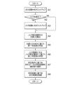
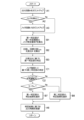
- Figures 3, 4, and 5 are flowchart showing an example of a control procedure by the engine control device 10.
- Figure 3 is a flowchart of control in which the judgment result of either the first judgment unit 11 or the second judgment unit 12 is selected based on a predetermined condition.
- Figure 4 is a flowchart of control in which the judgment result is selected based on a first condition
- Figure 5 is a flowchart of control in which the judgment result is selected based on a second condition and a third condition.
- the controls according to these flowcharts are repeatedly executed for each cylinder at a predetermined cycle while the engine 1 is operating.
- step A1 the number of ignitions n is counted up, and in step A2, it is determined whether or not a knock has been detected. At this time, the knock intensity S is also obtained. If a knock is not detected, control for this cycle ends. If a knock is detected, the process proceeds to step A3, where the number of knocks k is counted up. If a knock is not detected in step A2, step A3 is skipped (the number of knocks k is not counted up) and the process moves to step A4. In step A4, the knock occurrence probability P is calculated from the ignition number n and the knock number k, and the likelihood L of the knock occurrence probability P is calculated.
- step A5 the first judgment unit 11 judges whether or not it is necessary to change the ignition timing ⁇ based on the magnitude of the likelihood L. Meanwhile, in step A6, the second judgment unit 12 judges whether or not it is necessary to change the ignition timing ⁇ based on the knock intensity S or the knock occurrence probability P.
- step A7 the selection unit 13 selects the judgment result of either the first judgment unit 11 or the second judgment unit 12 based on a predetermined condition. In the subsequent step A8, the ignition timing ⁇ is controlled based on the judgment result selected in step A7.
- step B1 the first determination unit 11 calculates the knock occurrence probability P in the most recent first predetermined period. That is, the knock occurrence probability P is calculated based on the number of ignitions n and the number of knocks k from before the first predetermined period to the present.
- step B2 the first determination unit 11 calculates the likelihood L of this knock occurrence probability P, and also calculates the target likelihood L tgt and the likelihood ratio R.
- step B3 the first determination unit 11 determines whether or not it is necessary to change the ignition timing ⁇ based on the likelihood ratio R.
- step B4 the second determination unit 12 calculates the short knock probability P S in the most recent second predetermined period. That is, the short knock probability P S is calculated based on the number of ignitions n and the number of knocks k from before the second predetermined period to the present. The second predetermined period is shorter than the first predetermined period.
- step B5 the second determination unit 12 determines whether or not the ignition timing ⁇ needs to be changed based on the short knock probability P S.
- step B6 determines whether or not the short knock probability P S is equal to or less than the threshold value P th (the first condition is established).
- step B6 If the condition of step B6 is met, the process proceeds to step B7, where the selection unit 13 selects the judgment result of the first judgment unit 11. If the condition of step B6 is not met, the process proceeds to step B8, where the selection unit 13 selects the judgment result of the second judgment unit 12. In the subsequent step A8, the ignition timing ⁇ is controlled based on the judgment results selected in steps B7 and B8.
- step C1 the second determination unit 12 determines whether or not it is necessary to change the ignition timing ⁇ based on the knock intensity S.
- step C2 the selection unit 13 determines whether or not the operating state of the engine 1 is in a steady state (the second condition is satisfied). If the condition in step C2 is satisfied, the process proceeds to step C3, and if not, the process proceeds to step B8.
- step C3 the selection unit 13 determines whether the knock intensity S is less than a predetermined intensity Sth (the third condition is satisfied). If the condition in step C3 is satisfied, the process proceeds to step B7, and if not, the process proceeds to step B8.
- step B7 the selection unit 13 selects the determination result of the first determination unit 11, and in step B8, the selection unit 13 selects the determination result of the second determination unit 12.
- the ignition timing ⁇ is controlled based on the determination result selected in steps B7 and B8.
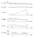
- FIG. 6A to 6F are graphs for explaining the control contents based on the judgment result by the first judgment unit 11.
- FIG. 6A shows the knock intensity S
- FIG. 6B shows the number of knocks k
- FIG. 6C shows the number of ignitions n
- FIG. 6D shows the knock occurrence probability P
- FIG. 6E shows the likelihood ratio R
- FIG. 6F shows the ignition timing ⁇ . Note that the occurrence or non-occurrence of a knock can also be determined from the knock intensity S.
- the value of the number of ignitions n increases every time ignition is performed by the spark plug 2, and the value of the number of knocks k increases every time a knock is detected. Every time the number of ignitions n changes, the knock occurrence probability P and the likelihood L are calculated, and the likelihood ratio R is calculated based on a preset target knock occurrence probability P tgt and a target likelihood L tgt (not shown).
- the first judgment unit 11 judges that the ignition timing ⁇ needs to be changed.
- the control unit 14 determines the direction of change of the ignition timing ⁇ based on the knock probability P at time t1.
- the control unit 14 controls the ignition timing ⁇ in the retard direction.
- the control unit 14 controls the retard amount so that the knock probability P matches the target knock probability Ptgt .
- the first determination unit 11 determines that the ignition timing ⁇ needs to be changed.
- the control unit 14 determines the direction of change of the ignition timing ⁇ based on the knock probability P at time t2 .
- the control unit 14 controls the ignition timing ⁇ in the advance direction. The control unit 14 controls the advance amount so that the knock probability P matches the target knock probability Ptgt .
- FIG. 7(A) to (G) are graphs for explaining the control content in which the determination result by the first determination unit 11 is selected when the first condition is satisfied, and the determination result by the second determination unit 12 is selected when the first condition is not satisfied.
- Fig. 7(A) represents the knock intensity S
- Fig. 7(B) represents the number of knocks k
- Fig. 7(C) represents the number of ignitions n
- Fig. 7(D) represents the knock occurrence probability P
- Fig. 7(E) represents the short knock occurrence probability P S
- Fig. 7(F) represents the likelihood ratio R
- Fig. 7(G) represents the ignition timing ⁇ .
- the value of the knock occurrence probability P is basically calculated to be a smaller value as the number of ignitions n, which corresponds to the denominator, increases.
- the value of the likelihood ratio R becomes less likely to decrease as the number of ignitions n increases, and becomes less likely to become equal to or less than the predetermined value Rth .
- the control unit 14 controls the ignition timing ⁇ based on the likelihood ratio R (the magnitude of the likelihood L). For example, if the likelihood ratio R exceeds a predetermined value R th , the ignition timing ⁇ is maintained as is. On the other hand, for example, if the likelihood ratio R is equal to or less than the predetermined value R th , control is performed to move the ignition timing ⁇ based on the knock probability P.
- the control unit 14 controls the ignition timing ⁇ based on the knock intensity S and the knock probability P. For example, when the knock probability P at time t3 is higher than the target knock probability P tgt , the control unit 14 controls the ignition timing ⁇ in the retard direction. The control based on the judgment result of the second judgment unit 12 is continued until time t4 when the likelihood ratio R becomes equal to or smaller than a predetermined value R th .
- control based on the judgment result of the second judgment unit 12 may be configured to gradually control the ignition timing ⁇ in the advance direction when the knock probability P is lower than the target knock probability P tgt , and to continue the ignition timing ⁇ until it returns to the ignition timing when the first condition is not satisfied (time t3 ).
Landscapes
- Engineering & Computer Science (AREA)
- Chemical & Material Sciences (AREA)
- Combustion & Propulsion (AREA)
- Mechanical Engineering (AREA)
- General Engineering & Computer Science (AREA)
- Signal Processing (AREA)
- Electrical Control Of Ignition Timing (AREA)
Abstract
開示のエンジン制御装置(10)は、エンジン(1)の点火時期(θ)を制御することでノックを抑制するエンジン制御装置(10)であり、第一判定部(11)と第二判定部(12)と選択部(13)とを備える。第一判定部(11)は、点火回数(n)及びノック回数(k)に基づいてノック発生確率(P)及び尤度(L)を算出し、尤度(L)の大きさに基づいて点火時期(θ)の変更の要否を判定する。第二判定部(12)は、ノック強度(S)又はノック発生確率(P)を算出し、ノック強度(S)又はノック発生確率(P)に基づいて点火時期(θ)の変更の要否を判定する。選択部(13)は、所定条件に基づき第一判定部(11)及び第二判定部(12)の何れか一方の判定結果を選択する。
Description
本件は、点火時期制御によりエンジンのノック(ノッキング)を抑制するエンジン制御装置に関する。
エンジンの点火時期制御において、ノックが発生しにくい点火時期の範囲内で出力トルクができるだけ大きくなるように、点火時期を調節するものが知られている。例えば、出力トルクが最大になる点火時期(MBT, Minimum advance for Best Torque)とノック限界点火時期(ノックが発生しない最進角の点火時期)とを算出し、これらのうち遅角側の値を用いて点火時期を制御する制御装置が知られている(特許文献1参照)。
一方、ノック限界点火時期は、気筒内における燃料混合気の分布形状,温度分布,圧力分布等の影響を受けて容易に変動する。そのため、ノック限界点火時期を精度よく算出することは難しく、例えばノックの発生を完全に押さえ込んだままエンジンを作動させ続けることは困難である。そこで、比較的小さなノックが発生した時点で点火時期を一時的に遅角方向へ移動させ、その後、点火時期を徐々に進角方向へ戻すことで、ノックの増強を抑制しつつ出力トルクを確保する制御手法が提案されている。このような制御は、ノックリタード制御と呼ばれている。
しかしながら、ノックリタード制御では点火時期が実際のノック限界点火時期よりも遅角寄りに制御されやすく、良好な燃費が得られないという課題がある。また、このような課題に対し、ノックリタード制御におけるリタード量を小さくすることや、点火時期を進角方向へ戻すときの速度(単位燃焼サイクルあたりの進角量)を大きくすることも考えられるが、これらの手法により、かえってノックが発生しやすくなることが懸念される。
本件の目的の一つは、上記のような課題に照らして創案されたものであり、ノックを抑制しつつ燃費を改善できるようにしたエンジン制御装置を提供することである。なお、この目的に限らず、後述する「発明を実施するための形態」に示す各構成から導き出される作用効果であって、従来の技術では得られない作用効果を奏することも、本件の他の目的として位置付けられる。
開示のエンジン制御装置は、以下に開示する態様(適用例)として実現でき、上記の課題の少なくとも一部を解決する。態様2以降の各態様は、何れもが付加的に適宜選択されうる態様であって、何れもが省略可能な態様である。態様2以降の各態様は、何れもが本件にとって必要不可欠な態様や構成を開示するものではない。
態様1.開示のエンジン制御装置は、エンジンの点火時期を制御することでノックを抑制するエンジン制御装置であって、第一判定部と第二判定部と選択部とを備える。前記第一判定部は、点火回数及びノック回数に基づいてノック発生確率及び前記ノック発生確率の尤度を算出し、前記尤度の大きさに基づいて前記点火時期の変更の要否を判定する。前記第二判定部は、ノック強度又は前記ノック発生確率を算出し、前記ノック強度又は前記ノック発生確率に基づいて前記点火時期の変更の要否を判定する。前記選択部は、所定条件に基づき前記第一判定部及び前記第二判定部の何れか一方の判定結果を選択する。
態様2.上記の態様1を含む態様に関し、前記第一判定部が、前記点火回数及び前記ノック回数と目標ノック発生確率とに基づいて目標尤度を算出するとともに前記尤度に対する前記目標尤度の比である尤度比を算出し、前記尤度比が所定値以下になった場合に前記点火時期の変更を要すると判定することが好ましい。
態様3.上記の態様1を含む態様に関し、前記点火回数及び前記ノック回数が、直近の第一所定期間における回数であることが好ましい。
態様4.上記の態様3を含む態様に関し、前記選択部が、前記第一所定期間よりも短い直近の第二所定期間における前記ノック発生確率が閾値以下であるという第一条件の成立時に前記第一判定部の判定結果を選択し、前記第一条件の不成立時に前記第二判定部の判定結果を選択することが好ましい。
態様4.上記の態様3を含む態様に関し、前記選択部が、前記第一所定期間よりも短い直近の第二所定期間における前記ノック発生確率が閾値以下であるという第一条件の成立時に前記第一判定部の判定結果を選択し、前記第一条件の不成立時に前記第二判定部の判定結果を選択することが好ましい。
態様5.上記の態様1を含む態様に関し、前記選択部が、前記エンジンが定常運転しているという第二条件の成立時に前記第一判定部の判定結果を選択し、前記第二条件の不成立時に前記第二判定部の判定結果を選択することが好ましい。
態様6.上記の態様5を含む態様に関し、前記尤度の値が、前記エンジンの前記定常運転と非定常運転との間での変更に際してリセットされることが好ましい。
態様6.上記の態様5を含む態様に関し、前記尤度の値が、前記エンジンの前記定常運転と非定常運転との間での変更に際してリセットされることが好ましい。
態様7.上記の態様1を含む態様に関し、前記選択部が、前記ノック強度が所定強度未満であるという第三条件の成立時に前記第一判定部の判定結果を選択し、前記第三条件の不成立時に前記第二判定部の判定結果を選択することが好ましい。
態様8.上記の態様1を含む態様に関し、前記点火時期と前記ノック発生確率との関係を表すベース特性マップを備え、前記ノック発生確率が前記ベース特性マップから算出される目標ノック発生確率に一致するように前記点火時期が制御されることが好ましい。
態様8.上記の態様1を含む態様に関し、前記点火時期と前記ノック発生確率との関係を表すベース特性マップを備え、前記ノック発生確率が前記ベース特性マップから算出される目標ノック発生確率に一致するように前記点火時期が制御されることが好ましい。
開示のエンジン制御装置によれば、第一判定部の判定結果と第二判定部の判定結果とを使い分けることにより、点火時期の制御精度を改善でき、ノックを抑制しつつ燃費を改善できる。
[1.構成]
図1は、実施例のエンジン制御装置10及びエンジン制御装置10が適用されるエンジン1の構成を示す図である。エンジン1は、気筒内に点火プラグ2を備えた火花点火方式の内燃機関であり、例えば自動車,船舶,駆動力生成装置,発電装置等に搭載されうる。図1に示すエンジン1は、自動車に搭載されている。点火プラグ2の点火タイミングは、エンジン制御装置10によって制御される。エンジン制御装置10は、プロセッサとメモリとを搭載した電子制御装置であり、エンジン1の点火時期θを制御することでノックを抑制する機能を持つ。エンジン制御装置10が実施する制御の内容は、例えばプログラムの形式でメモリに記録,保存される。
図1は、実施例のエンジン制御装置10及びエンジン制御装置10が適用されるエンジン1の構成を示す図である。エンジン1は、気筒内に点火プラグ2を備えた火花点火方式の内燃機関であり、例えば自動車,船舶,駆動力生成装置,発電装置等に搭載されうる。図1に示すエンジン1は、自動車に搭載されている。点火プラグ2の点火タイミングは、エンジン制御装置10によって制御される。エンジン制御装置10は、プロセッサとメモリとを搭載した電子制御装置であり、エンジン1の点火時期θを制御することでノックを抑制する機能を持つ。エンジン制御装置10が実施する制御の内容は、例えばプログラムの形式でメモリに記録,保存される。
エンジン制御装置10は、例えばエンジン1の作動状態,燃焼噴射方式,燃焼方式,燃料噴射量,燃焼条件,車両走行状態等に応じた点火時期θで点火プラグ2を作動させる。エンジン1の気筒数,ストローク数,燃焼噴射方式,燃焼方式に制限はない。エンジン1の燃料噴射装置は、例えば吸気通路,吸気ポート,気筒内のうち少なくとも何れかの箇所に設けられ、複数の箇所に設けられることもある。
エンジン1には、エンジン1の作動状態に関する情報を検出するセンサとして、ノックセンサ3,水温センサ4,クランク角センサ5,エアフローセンサ6が設けられる。ノックセンサ3はノック(ノッキング)の発生有無及び強度を検出し、水温センサ4はエンジン冷却水温を検出する。クランク角センサ5はクランク角やクランク角速度(エンジン回転数)を検出し、エアフローセンサ6は吸気量を検出する。本実施例では、エンジン制御装置10にアクセル開度センサ7と車速センサ8とが接続される。アクセル開度センサ7は、エンジン1が搭載された車両のアクセル開度を検出し、車速センサ8は車速を検出する。各センサ3~8で検出された情報はエンジン制御装置10に入力される。
エンジン制御装置10は、第一判定部11,第二判定部12,選択部13,制御部14を備える。これらの要素は、エンジン制御装置10の機能を表現したものであり、例えばエンジン制御装置10内のメモリや補助記憶装置に記録,保存されるソフトウェアとしてプログラミングされうる。また、そのソフトウェアに対応する電子回路(ハードウェア)として実現されうる。あるいは、ソフトウェアとハードウェアとが混在するシステムとして実現されうる。
第一判定部11及び第二判定部12は、ともに点火時期θの変更の要否を判定するものである。第二判定部12は、従来のノックリタード制御と同様の判定を行う判定部である。これに対し、第一判定部11は、従来のノックリタード制御とは異なる判定を行う判定部である。第一判定部11及び第二判定部12は、互いに独立して判定を実施する。その後、選択部13が所定条件に基づき、第一判定部11及び第二判定部12の何れか一方の判定結果を選択する。選択部13で選択された判定結果は制御部14に伝達される。制御部14は、その判定結果に基づいて点火時期θを制御する。
第二判定部12は、ノックの発生有無,ノック強度S又はノック発生確率Pを検出又は算出し、点火時期θの変更の要否を判定する。第二判定部12は、ノックの発生有無のみに基づく判定を実施してもよく、ノック強度Sのみに基づく判定を実施してもよく、ノック発生確率Pのみに基づく判定を実施してもよく、ノック強度S及びノック発生確率Pに基づく判定を実施してもよい。具体的な判定条件及び点火時期θの変更量の設定には、公知の手法を適用可能である。
第二判定部12における判定手法の一例として、ノックの発生有無に基づく判定手法を説明する。第二判定部12は、ノックセンサ3でノックの発生が検出された場合は点火時期θを所定量遅角方向(リタード方向)へ変更し、ノックの発生が検出されなかった場合は点火時期θを徐々に進角させる。
第二判定部12における別の判定手法の例として、ノック強度Sに基づく判定手法を説明する。第二判定部12は、ノックセンサ3で検出されたノック強度Sが第一強度以上である場合に、点火時期θの遅角方向(リタード方向)への変更を要すると判定する。ノック強度Sが第一強度よりも小さい場合には、点火時期θの進角方向(アドバンス方向)への変更を要すると判定する。
第二判定部12における別の判定手法の例として、ノック発生確率Pに基づく判定手法を説明する。第二判定部12は、エンジン1の点火回数nとノックセンサ3の検出結果からカウント(カウントアップ)されるノック回数kとに基づき、ノック発生確率P(=k/n)を算出する。点火回数n及びノック回数kがカウントされる期間は、エンジン1の始動開始時から現在までの期間であってもよいし、直近の第一所定期間(例えば、現在から数百回分前までの点火回数nや現在から数十秒前まで等)であってもよい。
また、第二判定部12は、ノック発生確率Pが第一確率以上である場合に、点火時期θの遅角方向への変更を要すると判定する。ノック発生確率Pが第一確率よりも小さい場合には、点火時期θの変更を要しないと判定する。
第一判定部11は、エンジン1の点火回数nとノックセンサ3の検出結果からカウントされるノック回数kとに基づき、ノック発生確率P(=k/n)を算出するとともに、ノック発生確率Pの尤度Lを算出する。また、第一判定部11は、尤度Lの大きさに基づいて点火時期θの変更の要否を判定する。尤度Lは、ノック発生確率Pの値の確からしさや信頼性の高さに対応するパラメータである。本実施形態では、正規化した尤度Lを使用する。尤度Lの正規化は、現在のノック発生確率Pのときの尤度Lを、ノック発生確率Pが0のときから1のときまでの尤度Lの積分値で割ることで行えばよい。尤度Lは、点火回数nが増加するに連れて小さな値をとりにくく(高い信頼性が得られやすく)なる。尤度Lの算出式を以下に示す。

第一判定部11における判定手法の一例として、尤度Lの大きさに基づく判定手法を説明する。第一判定部11は、尤度Lの大きさが第一尤度以上である場合に、点火時期θの変更を要すると判定する。点火時期θの変更方向(遅角方向,進角方向)は、尤度Lの大きさが第一尤度以上になった時点におけるノック発生確率Pに基づいて判断する。また、尤度Lの大きさが第一尤度未満である場合には、点火時期θの変更を要しない(点火時期θを移動させなくてよい)と判定する。
第一判定部11における別の判定手法の例として、尤度比Rに基づく判定手法を説明する。第一判定部11は、目標尤度Ltgtと尤度Lに対する目標尤度Ltgtの比である尤度比Rとを算出する。目標尤度Ltgtは、点火回数n及びノック回数kと目標ノック発生確率Ptgtとから算出される。目標ノック発生確率Ptgtは、現在のエンジン1の運転状態における理想的なノック発生確率Pであり、好ましくは0より大きな値である。すなわち、ノック発生確率Pが0ということは、もう少し点火時期θをアドバンスできる可能性が有るということなので、理想的な点火時期θであるとは言い切れない。一方、ノック発生確率Pが大きすぎる場合は、エンジン1の破損につながる虞がある。よって、目標ノック発生確率Ptgtは、大きすぎず、小さすぎない値に設定されることが好ましい。また、目標ノック発生確率Ptgtは、予め設定された固定値であってもよいし、エンジン1の実際の点火時期θやエンジン回転数,エンジン負荷に応じて算出される可変値であってもよい。目標尤度Ltgt及び尤度比Rの算出式を以下に示す。

尤度比Rの値は、実際のノック発生確率Pがほぼ目標ノック発生確率Ptgtに等しい運転状態になっていれば、1に近い値に維持される。また、実際のノック発生確率Pが目標ノック発生確率Ptgtと相違する運転状態になっている場合、点火回数nが増加するに連れて尤度比Rの値が小さくなりやすい。また、尤度比Rの低下速度は、点火回数nが増加するに連れて減少する。
図2は、エンジン1の点火時期θとノック発生確率Pとの関係を表すグラフが規定されたベース特性マップ15である。本実施例のエンジン制御装置10(制御部14)は、事前に実施された試験や実験を通じて作成された、エンジン1の理想状態(定常運転、所定温度、標準大気圧下、吸気、排気センサ活性状態、インジェクタ新品、等)でのベース特性マップ15を記憶している。図2のグラフのX軸は、点火時期θを上死点からの遅角方向へのクランク角[°CA BTDC]で表現したものであり、図中の右側が進角(アドバンス)側であり、左側が遅角(リタード)側である。目標ノック発生確率Ptgtは、エンジン回転数及び/又はエンジン負荷に応じて設定され、このベース特性マップ15のグラフに基づいて後述する点火時期であるベース点火時期θBが算出される。なお、ベース特性マップ15は、エンジン1の目標トルクや吸入空気量、燃料噴射量等に応じて複数記憶されていてもよい。
第一判定部11は、尤度比Rが所定値Rth以下になった場合(すなわち、目標尤度Ltgtに対して尤度Lが十分に大きくなった場合)に「点火回数nが十分にあり、かつ、点火時期θが不適切である」と判断し、点火時期θの変更を要すると判定する。点火時期θの変更方向(遅角方向,進角方向)は、尤度比Rが所定値Rth以下になった時点におけるノック発生確率Pに基づいて判断する。例えば、ノック発生確率Pが目標ノック発生確率Ptgtよりも高ければ、点火時期θをリタードさせる必要があると判定する。反対に、ノック発生確率Pが目標ノック発生確率Ptgtよりも低ければ、点火時期θをアドバンスさせる必要があると判定する。
点火時期θの変更量(リタード量,アドバンス量)は、予め設定された固定値であってもよいし、ノック発生確率Pに応じて算出される可変値であってもよい。また、ノック発生確率Pがベース特性マップ15のグラフから算出される目標ノック発生確率Ptgtに一致するように、点火時期θの変更量(リタード量,アドバンス量)を設定してもよい。例えば、図2に示すベース特性マップ15のグラフ上において、Y座標が現在のノック発生確率PAに対応する点を検索(算出)し、その点のX座標を算出点火時期θAと定義する。また、ベース特性マップ上の目標ノック発生確率Ptgtに対応する点火時期をベース点火時期θBと定義する。点火時期制御を行うにあたり、制御初期は目標ノック発生確率Ptgtに対応する点火時期、すなわちベース点火時期θBに点火時期θが設定される。
ここで、現在の点火時期θreal(=ベース点火時期θB)における現在のノック発生確率PAが目標ノック発生確率Ptgtよりも高い場合には、算出点火時期θAが現在の点火時期θrealよりも進角側に位置することから、ベース特性マップ15に沿って現在のノック発生確率PAを目標ノック発生確率Ptgtに近づけようとすると、点火時期θをリタードさせる必要がある。そこで、例えばベース点火時期θBと算出点火時期θAとの差に相当するリタード量Δθを設定し、点火時期θを遅角方向へリタード量Δθだけ移動させればよい。
また、現在のノック発生確率PAが目標ノック発生確率Ptgtよりも低い場合には、算出点火時期θAがベース点火時期θBよりも遅角側に位置することから、ベース特性マップに沿って現在のノック発生確率PAを目標ノック発生確率Ptgtに近づけようとすると、点火時期θをアドバンスさせる必要がある。そこで、例えばベース点火時期θBと算出点火時期θAとの差に相当するアドバンス量Δθを設定し、点火時期θを進角方向へアドバンス量Δθだけ移動させればよい。
点火時期を移動させた後も同様に、点火時期移動後のノック発生確率PAに対応する算出点火時期θAを算出し、ベース点火時期θBと算出点火時期θAとの差に基づいて点火時期θを移動量Δθ(リタード量Δθ,アドバンス量Δθ)だけ移動させればよい。第一判定部11により点火時期θの変更を要すると判定されるたびに上記方法により点火時期を更新する。最新の点火時期は、ベース点火時期θBに、今までの点火時期θの移動量Δθを積算した値となる(移動量Δθは、進角側を正の値、遅角側を負の値とする)。
選択部13は、所定条件に基づき第一判定部11及び第二判定部12の何れか一方の判定結果を選択するものである。選択部13は、例えば以下に例示する第一条件の成立時に第一判定部11の判定結果を選択し、第一条件の不成立時に第二判定部12の判定結果を選択しうる。
第一条件:第一所定期間よりも短い直近の第二所定期間における短期ノック発生確率PSが閾値Pth以下であること。
第一条件:第一所定期間よりも短い直近の第二所定期間における短期ノック発生確率PSが閾値Pth以下であること。
上記の第一所定期間は、第一判定部11がノック発生確率Pを算出する際に参照する直近の対象期間を意味し、第二所定期間は、第二判定部12が短期ノック発生確率PSを算出する際に参照する直近の対象期間を意味する。第二所定期間は、例えば、現在から数十回分前までの点火回数nや現在から数秒前まで等である。第二所定期間におけるノック回数kをkSとおき、第二所定期間における点火回数nをnSとおけば、短期ノック発生確率PSはkS/nSと表現される。第二判定部12が算出する短期ノック発生確率PSは、短いスパンでノックが頻発した場合に増加し、ノックが発生しない場合は比較的短時間で減少する。第一条件に基づく選択により、短期間での連続ノック(短時間での頻繁なノック,連続的ノック,間欠ノック)の発生時に第一判定部11の判定結果よりも第二判定部12の判定結果が優先して採用される。
選択部13は、例えば以下に例示する第二条件の成立時に第一判定部11の判定結果を選択し、第二条件の不成立時に第二判定部12の判定結果を選択しうる。
第二条件:エンジン1が定常運転していること。
エンジン1の運転状態が定常状態であるか否かについては、エンジン1の出力変動,トルク変動,エンジン回転数の変動等に基づいて判定してもよいし、吸入空気量,アクセル開度,車速等の変動に基づいて判定してもよい。第二条件に基づく選択により、エンジン1の運転状態が変化した場合(非定常状態となった場合)に、第一判定部11の判定結果よりも第二判定部12の判定結果が優先して採用される。なお、エンジン1の作動状態が定常運転と非定常運転との間で切り替わった場合には、第一判定部11により尤度Lの値がリセットされることが好ましく、点火回数n及びノック回数kのカウントもリセットされることが好ましい。このため、第二条件の不成立時には、第二判定部12はノックの発生有無、若しくはノック強度Sに基づく判定手法を実施するのが好ましい。
第二条件:エンジン1が定常運転していること。
エンジン1の運転状態が定常状態であるか否かについては、エンジン1の出力変動,トルク変動,エンジン回転数の変動等に基づいて判定してもよいし、吸入空気量,アクセル開度,車速等の変動に基づいて判定してもよい。第二条件に基づく選択により、エンジン1の運転状態が変化した場合(非定常状態となった場合)に、第一判定部11の判定結果よりも第二判定部12の判定結果が優先して採用される。なお、エンジン1の作動状態が定常運転と非定常運転との間で切り替わった場合には、第一判定部11により尤度Lの値がリセットされることが好ましく、点火回数n及びノック回数kのカウントもリセットされることが好ましい。このため、第二条件の不成立時には、第二判定部12はノックの発生有無、若しくはノック強度Sに基づく判定手法を実施するのが好ましい。
選択部13は、例えば以下に例示する第三条件の成立時に第一判定部11の判定結果を選択し、第三条件の不成立時に第二判定部12の判定結果を選択しうる。
第三条件:ノック強度Sが所定強度Sth未満であること。
ここでいうノック強度Sとしては、ノックセンサ3で検出されたものをそのまま用いてもよいし、エンジン1の出力,トルク,エンジン回転数等に基づいて補正されたものを用いてもよい。第三条件に基づく選択により、強いノックが生じた場合に、第一判定部11の判定結果よりも第二判定部12の判定結果が優先して採用される。
第三条件:ノック強度Sが所定強度Sth未満であること。
ここでいうノック強度Sとしては、ノックセンサ3で検出されたものをそのまま用いてもよいし、エンジン1の出力,トルク,エンジン回転数等に基づいて補正されたものを用いてもよい。第三条件に基づく選択により、強いノックが生じた場合に、第一判定部11の判定結果よりも第二判定部12の判定結果が優先して採用される。
選択部13が判定結果を選択する際に参照される所定条件には、上記の第一条件,第二条件,第三条件以外の条件も含まれる。例えば、ユーザの選択(ユーザに操作されるスイッチの操作状態や制御用設定項目の設定状態)に応じて一方の判定結果が選択されるようにしてもよいし、エンジン1の連続作動時間や車両の走行状態等に応じて一方の判定結果が選択されるようにしてもよい。また、上記の第一条件,第二条件,第三条件は、後述する図5のフローチャートのように、組み合わされてもよい。複数の条件を組み合わせる場合には、例えば、全ての条件が成立したときに第一判定部11の判定結果を選択し、いずれかの条件が成立しないときに第二判定部12の判定結果を選択してよい。
制御部14は、選択部13で選択された判定結果に基づき、点火時期θを制御するものである。選択部13で選択された判定結果が第一判定部11による判定結果だった場合、制御部14は、ノック発生確率Pに基づいて点火時期θのリタード量又はアドバンス量を設定して点火時期θを制御する。例えば、ノック発生確率Pが目標ノック発生確率Ptgtよりも高い場合には、ノック発生確率Pが目標ノック発生確率Ptgtに近づくようにリタード量を設定して点火時期θを遅角方向へ移動させる。また、ノック発生確率Pが目標ノック発生確率Ptgtよりも低い場合には、ノック発生確率Pが目標ノック発生確率Ptgtに近づくようにアドバンス量を設定して点火時期θを進角方向へ移動させる。
選択部13で選択された判定結果が第二判定部12による判定結果だった場合、制御部14は、ノック強度Sに基づいて点火時期θを制御してもよいし、ノック発生確率Pに基づいて点火時期θを制御してもよい。あるいは、従来のノックリタード制御と同様の制御を実施してもよい。例えば、予め設定されたリタード量で点火時期θを一時的にリタードさせ、その後、点火時期θを徐々に進角方向へ戻すようにしてもよい。
[2.フローチャート]
図3,図4,図5の各々は、エンジン制御装置10による制御手順の一例を示すフローチャートである。図3は、所定条件に基づいて第一判定部11及び第二判定部12の何れか一方の判定結果が選択される制御のフローチャートである。図4は、第一条件に基づいて判定結果が選択される制御のフローチャートであり、図5は、第二条件及び第三条件に基づいて判定結果が選択される制御のフローチャートである。これらのフローチャートに係る制御は、エンジン1が作動している間に、各々の気筒に対して所定の周期で繰り返し実行される。
図3,図4,図5の各々は、エンジン制御装置10による制御手順の一例を示すフローチャートである。図3は、所定条件に基づいて第一判定部11及び第二判定部12の何れか一方の判定結果が選択される制御のフローチャートである。図4は、第一条件に基づいて判定結果が選択される制御のフローチャートであり、図5は、第二条件及び第三条件に基づいて判定結果が選択される制御のフローチャートである。これらのフローチャートに係る制御は、エンジン1が作動している間に、各々の気筒に対して所定の周期で繰り返し実行される。
図3のフローチャートについて説明する。ステップA1では点火回数nがカウントアップされ、ステップA2ではノックを検出したか否かが判定される。このとき、あわせてノック強度Sも取得する。ノックを検出しない場合にはこの周期の制御が終了する。ノックを検出した場合にはステップA3に進み、ノック回数kがカウントアップされる。ステップA2でノックを検出しない場合には、ステップA3をスキップして(ノック回数kのカウントアップを行わず)ステップA4に移行する。ステップA4では、点火回数n及びノック回数kからノック発生確率Pが算出されるとともに、ノック発生確率Pの尤度Lが算出される。
続くステップA5では、第一判定部11において、尤度Lの大きさに基づいて点火時期θの変更の要否が判定される。一方、ステップA6では、第二判定部12において、ノック強度S又はノック発生確率Pに基づいて点火時期θの変更の要否が判定される。ステップA7では、選択部13において、所定条件に基づき、第一判定部11及び第二判定部12の何れか一方の判定結果が選択される。その後のステップA8では、ステップA7で選択された判定結果に基づき、点火時期θが制御される。
図4のフローチャートについて説明する。図4のフローチャートのうち、ステップA1~A3,A8は図3のフローチャートと同一である。ステップA3に続くステップB1では、第一判定部11において、直近の第一所定期間におけるノック発生確率Pが算出される。すなわち、第一所定期間前から現在までにおける点火回数n及びノック回数kに基づきノック発生確率Pが算出される。ステップB2では、第一判定部11において、このノック発生確率Pの尤度Lが算出されるとともに、目標尤度Ltgt及び尤度比Rが算出される。ステップB3では、第一判定部11において、尤度比Rに基づいて点火時期θの変更の要否が判定される。
一方、ステップB4では、第二判定部12において、直近の第二所定期間における短期ノック発生確率PSが算出される。すなわち、第二所定期間前から現在までにおける点火回数n及びノック回数kに基づき短期ノック発生確率PSが算出される。第二所定期間は、第一所定期間よりも短い期間である。続くステップB5では、第二判定部12において、短期ノック発生確率PSに基づいて点火時期θの変更の要否が判定される。ステップB6では、選択部13において、短期ノック発生確率PSが閾値Pth以下である(第一条件が成立する)か否かが判定される。
ステップB6の条件が成立する場合にはステップB7に進み、選択部13において、第一判定部11の判定結果が選択される。ステップB6の条件が成立しない場合にはステップB8に進み、選択部13において、第二判定部12の判定結果が選択される。その後のステップA8では、ステップB7,B8で選択された判定結果に基づき、点火時期θが制御される。
図5のフローチャートについて説明する。図5のフローチャートのうち、ステップA1~A3,B1~B3,B7,B8,A8は図4のフローチャートと同一である。ステップB3に続くステップC1では、第二判定部12において、ノック強度Sに基づいて点火時期θの変更の要否が判定される。ステップC2では、選択部13において、エンジン1の運転状態が定常状態である(第二条件が成立する)か否かが判定される。ステップC2の条件が成立する場合にはステップC3に進み、成立しない場合にはステップB8に進む。
ステップC3では、選択部13において、ノック強度Sが所定強度Sth未満である(第三条件が成立する)か否かが判定される。ステップC3の条件が成立する場合にはステップB7に進み、成立しない場合にはステップB8に進む。ステップB7では、選択部13において第一判定部11の判定結果が選択され、ステップB8では、選択部13において第二判定部12の判定結果が選択される。その後のステップA8では、ステップB7,B8で選択された判定結果に基づき、点火時期θが制御される。
[3.グラフ]
図6(A)~(F)は、第一判定部11による判定結果に基づく制御内容を説明するためのグラフである。図6(A)はノック強度S、図6(B)はノック回数k、図6(C)は点火回数n、図6(D)はノック発生確率P、図6(E)は尤度比R、図6(F)は点火時期θを表す。なお、ノック強度Sからノックの発生有無も判定できる。点火回数nの値は、点火プラグ2による点火が実施される度に増加し、ノック回数kの値は、ノックが検出される度に増加する。点火回数nが変化する度にノック発生確率P及び尤度Lが算出され、予め設定された目標ノック発生確率Ptgtや図示しない目標尤度Ltgtに基づいて、尤度比Rが算出される。
図6(A)~(F)は、第一判定部11による判定結果に基づく制御内容を説明するためのグラフである。図6(A)はノック強度S、図6(B)はノック回数k、図6(C)は点火回数n、図6(D)はノック発生確率P、図6(E)は尤度比R、図6(F)は点火時期θを表す。なお、ノック強度Sからノックの発生有無も判定できる。点火回数nの値は、点火プラグ2による点火が実施される度に増加し、ノック回数kの値は、ノックが検出される度に増加する。点火回数nが変化する度にノック発生確率P及び尤度Lが算出され、予め設定された目標ノック発生確率Ptgtや図示しない目標尤度Ltgtに基づいて、尤度比Rが算出される。
時刻t1に尤度比Rが所定値Rth以下になると、第一判定部11が点火時期θの変更を要すると判定する。この判定結果が選択部13で選択されると、制御部14は時刻t1のノック発生確率Pに基づいて点火時期θの変更方向を判断する。時刻t1のノック発生確率Pが目標ノック発生確率Ptgtよりも高い場合、制御部14は点火時期θを遅角方向に制御する。制御部14はノック発生確率Pが目標ノック発生確率Ptgtに一致するようにリタード量を制御する。点火時期θが変更されると、それまでの間にカウントされていた点火回数n及びノック回数kの値がリセットされる。
その後の時刻t2に尤度比Rが再び所定値Rth以下になると、第一判定部11が点火時期θの変更を要すると判定する。この判定結果が選択部13で選択されると、制御部14は時刻t2のノック発生確率Pに基づいて点火時期θの変更方向を判断する。時刻t2のノック発生確率Pが目標ノック発生確率Ptgtよりも低い場合、制御部14は点火時期θを進角方向に制御する。制御部14はノック発生確率Pが目標ノック発生確率Ptgtに一致するようにアドバンス量を制御する。
図7(A)~(G)は、第一条件の成立時に第一判定部11による判定結果が選択され、第一条件の不成立時に第二判定部12による判定結果が選択される制御内容を説明するためのグラフである。図7(A)はノック強度S、図7(B)はノック回数k、図7(C)は点火回数n、図7(D)はノック発生確率P、図7(E)は短期ノック発生確率PS、図7(F)は尤度比R、図7(G)は点火時期θを表す。
第一判定部11は、図7(B)に示すように、比較的長い直近の第一所定期間を対象期間としてノック回数k及び点火回数nをカウントし、これらの値に基づいてノック発生確率P(=k/n)を算出する。ノック発生確率Pの値は、図7(C)に示すように、基本的には分母に相当する点火回数nが増加するほど小さい値として算出される。一方、尤度比Rの値は点火回数nが増加するほど低下しにくくなり、所定値Rth以下になりにくくなる。
第二判定部12は、ノック強度Sやノック発生確率Pに基づいて点火時期θの変更の要否を判定する。また、図7(E)に示すように、第一所定期間よりも短い第二所定期間を対象期間としてノック回数kS及び点火回数nSをカウントし、これらの値に基づいて短期ノック発生確率PS(=kS/nS)を算出する。短期ノック発生確率PSの値は、第二所定期間の間にノックが発生しなければ0になり、連続ノックが発生すると急激に増加する。
短期ノック発生確率PSが閾値Pth以下である場合、第一条件が成立し、選択部13が第一判定部11の判定結果を選択する。これにより、制御部14は尤度比R(尤度Lの大きさ)に基づいて点火時期θを制御する。例えば、尤度比Rが所定値Rthを超えているならば、点火時期θがそのまま維持される。また、例えば尤度比Rが所定値Rth以下ならば、ノック発生確率Pに基づいて点火時期θを移動させる制御が実施される。
時刻t3に短期ノック発生確率PSが閾値Pthを超えると、第一条件が不成立となり、選択部13が第二判定部12の判定結果を選択する。これにより、制御部14はノック強度Sやノック発生確率Pに基づいて点火時期θを制御する。例えば、時刻t3のノック発生確率Pが目標ノック発生確率Ptgtよりも高い場合、制御部14は点火時期θを遅角方向に制御する。第二判定部12の判定結果に基づく制御は、尤度比Rが所定値Rth以下になる時刻t4まで継続される。なお、第二判定部12の判定結果に基づく制御は、ノック発生確率Pが目標ノック発生確率Ptgtよりも低い場合に点火時期θを徐々に進角方向に制御し、点火時期θは第一条件が不成立となったとき(時刻t3)の点火時期に戻るまで継続されるものとしてもよい。
図8(A)~(G)は、第二条件及び第三条件の成立時に第一判定部11による判定結果が選択され、第二条件又は第三条件の不成立時に第二判定部12による判定結果が選択される制御内容を説明するためのグラフである。図8(A)はノック強度S、図8(B)はノック回数k、図8(C)は点火回数n、図8(D)はノック発生確率P、図8(E)はエンジントルク、図8(F)は尤度比R、図8(G)は点火時期θを表す。
エンジン1が定常運転(エンジントルクがほぼ一定)の状態であって、ノック強度Sが所定強度Sth未満であるとき、第二条件及び第三条件が成立し、選択部13が第一判定部11の判定結果を選択する。これにより、制御部14は尤度比R(尤度Lの大きさ)に基づいて点火時期θを制御する。例えば、尤度比Rが所定値Rthを超えているならば、点火時期θがそのまま維持される。
時刻t5にノック強度Sが所定強度Sth以上になると、第三条件が不成立となり、選択部13が第二判定部12の判定結果を選択する。これにより、制御部14はノック強度Sやノック発生確率Pに基づいて点火時期θを制御する。例えば、時刻t5のノック強度Sに応じたリタード量が設定され、点火時期θが一時的に遅角方向へ移動する。このとき、ノック回数kや点火回数nのカウントがリセットされ、第一判定部11による判定が停止する。その後、点火時期θを徐々に進角方向へ戻すような制御がなされる。点火時期θが元に戻る(時刻t5での値となる)前に再びノックが検出された場合には、ノック強度Sに応じたリタードが繰り返される。時刻t6に点火時期θが元に戻ると、第一判定部11による判定が再開される。
時刻t7に尤度比Rが所定値Rth以下になると、第一判定部11が点火時期θの変更を要すると判定する。このとき、第二条件及び第三条件が成立しているため、第一判定部11の判定結果が選択部13で選択される。制御部14は、例えば時刻t7のノック発生確率Pに基づいて点火時期θを制御する。点火時期θが変更されると、それまでの間にカウントされていた点火回数n及びノック回数kの値がリセットされるとともに、尤度Lの値がリセットされる。
時刻t8~t10は、エンジントルクが大きく変動し、エンジン1の作動状態が非定常運転になっている期間である。この期間では第二条件は不成立となり、選択部13が第二判定部12の判定結果を選択する。例えば、この期間内である時刻t9にノックが検出されると、時刻t9のノック強度Sに応じたリタード量が設定され、点火時期θを一時的に遅角方向へ移動させた後に徐々に進角方向へ戻すような制御がなされる。なお、時刻t10にエンジン1の作動状態が定常運転に戻ると第二条件が成立し、第一判定部11の判定結果が選択可能な状態となる。このとき、時刻t9で変更された点火時期θが元の値(時刻t9で変更される前の点火時期θ)に戻るまで、第一判定部11の判定は再開されない。
[4.効果]
(1)上記のエンジン制御装置10は、エンジン1の点火時期θを制御することでノックを抑制するエンジン制御装置10であって、第一判定部11と第二判定部12と選択部13とを備える。第一判定部11は、点火回数n及びノック回数kに基づいてノック発生確率P及びノック発生確率Pの尤度Lを算出し、尤度Lの大きさに基づいて点火時期θの変更の要否を判定する。第二判定部12は、ノック強度S又はノック発生確率Pを算出し、ノック強度S又はノック発生確率Pに基づいて点火時期θの変更の要否を判定する。選択部13は、所定条件に基づき第一判定部11及び第二判定部12の何れか一方の判定結果を選択する。
(1)上記のエンジン制御装置10は、エンジン1の点火時期θを制御することでノックを抑制するエンジン制御装置10であって、第一判定部11と第二判定部12と選択部13とを備える。第一判定部11は、点火回数n及びノック回数kに基づいてノック発生確率P及びノック発生確率Pの尤度Lを算出し、尤度Lの大きさに基づいて点火時期θの変更の要否を判定する。第二判定部12は、ノック強度S又はノック発生確率Pを算出し、ノック強度S又はノック発生確率Pに基づいて点火時期θの変更の要否を判定する。選択部13は、所定条件に基づき第一判定部11及び第二判定部12の何れか一方の判定結果を選択する。
このように、第一判定部11の判定結果と第二判定部12の判定結果とを所定条件に応じて使い分けることにより、点火時期θの制御精度を改善でき、ノックを抑制しつつ燃費を改善できる。例えば、第一判定部11の判定精度が向上しやすいエンジン1の運転状態で第一判定部11の判定結果を採用することで、従来のノックリタード制御よりも点火時期θをややアドバンス寄りに維持しやすくなり、ノックを抑制しつつ燃費を改善できる。また、第一判定部11の判定精度が低下しやすいエンジン1の運転状態では第二判定部12の判定結果を採用することで、従来のノックリタード制御と同等の燃費でノックを抑制できる。
(2)上記の第一判定部11は、点火回数n及びノック回数kと目標ノック発生確率Ptgtとに基づいて目標尤度Ltgtを算出するとともに尤度Lに対する目標尤度Ltgtの比である尤度比Rを算出し、尤度比Rが所定値Rth以下になった場合に点火時期θの変更を要すると判定しうる。尤度比Rの値は、点火回数nが十分にあり、かつ、点火時期θが不適切である場合に小さくなる。したがって、尤度比Rと所定値Rthとの大小関係を評価することで、第一判定部11による判定結果の信頼性を高めることができ、点火時期θの制御精度をさらに改善できる。
(3)上記のエンジン制御装置10において、点火回数n及びノック回数kは、例えば直近の第一所定期間における回数である。このような構成により、直近のエンジン1の作動状態をノック発生確率P及びその尤度Lに反映させることができ、点火時期θの変更タイミングを精度よく判定できる。したがって、点火時期θの制御精度を改善でき、ノックを抑制しつつ燃費を改善できる。
(4)上記の選択部13は、第一所定期間よりも短い直近の第二所定期間における短期ノック発生確率PSが閾値Pth以下であるという第一条件の成立時に第一判定部11の判定結果を選択し、第一条件の不成立時に第二判定部12の判定結果を選択しうる。このように、短期間での頻繁なノック(連続ノック)の発生時に第一判定部11の判定結果よりも第二判定部12の判定結果を優先することで、エンジン1のノック抑制効果を向上させることができる。すなわち、連続ノックが発生しても、点火回数nが多ければ尤度Lや尤度比Rは大きく変化しないことが考えられ、ノック抑制が遅れる可能性が有るため、連続ノックを検知した場合は、第二判定部12の判定結果を優先することで早期にノック抑制を行う。また、連続ノックが発生していなければ第一判定部11の判定結果を優先することで、従来のノックリタード制御よりも点火時期θをややアドバンス寄りに維持でき、燃費を改善できる。
(5)上記の選択部13は、エンジン1が定常運転しているという第二条件の成立時に第一判定部11の判定結果を選択し、第二条件の不成立時に第二判定部12の判定結果を選択しうる。このような選択により、エンジン1の作動状態が安定している場合の燃費を改善できる。また、エンジン1の作動状態が過渡的に変動している場合には、エンジン1のノック抑制効果を向上させることができる。すなわち、エンジン1の作動状態が過渡的に変動している場合には、点火時期θとノック発生確率Pとの関係性が変化する(図2のベース特性マップと異なる)と考えられ、点火時期θをどれだけ移動させれば良いか正確に算出することができない可能性が有るため、第二判定部12の判定結果を選択することでエンジン1のノックを抑制する。
(6)上記のエンジン制御装置10において、尤度Lの値は、例えばエンジン1の定常運転と非定常運転との間での変更に際してリセットされる。また、点火回数nやノック回数kについても、定常運転と非定常運転との間での変更に際してリセットされる。これにより、尤度Lや尤度比Rの算出精度を高めることができ、点火時期θの変更タイミングを精度よく判定できる。したがって、点火時期θの制御精度を改善でき、ノックを抑制しつつ燃費を改善できる。なお、エンジン1の定常運転と非定常運転との間での変更に限らず、点火時期θが変更された場合に尤度Lの値をリセットしてもよい。
(7)上記の選択部13は、ノック強度Sが所定強度Sth未満であるという第三条件の成立時に第一判定部11の判定結果を選択し、第三条件の不成立時に第二判定部12の判定結果を選択しうる。このように、強いノックの発生時に第一判定部11の判定結果よりも第二判定部12の判定結果を優先することで、エンジン1のノック抑制効果を向上させることができる。また、強いノックが発生していなければ第一判定部11の判定結果を優先することで、従来のノックリタード制御よりも点火時期θをややアドバンス寄りに維持でき、燃費を改善できる。
(8)上記のエンジン制御装置10は、点火時期θとノック発生確率Pとの関係を表すベース特性マップ15を備える。エンジン1の点火時期θは、ノック発生確率Pがベース特性マップ15から算出される目標ノック発生確率Ptgtに一致するように制御される。例えば、図2に示すベース特性マップ15のグラフ上において、Y座標がノック発生確率Pに対応する点のX座標であるベース点火時期θBが算出される。その後、ベース点火時期θBと実際の点火時期θrealとの差に基づいて点火時期θが制御される。このように、ノック発生確率Pを目標ノック発生確率Ptgtに追従させることで、点火時期θを適切に変化させること、すなわち不要に大きく変化させることを抑制でき、ノックを抑制しつつ燃費を改善できる。
[5.その他]
上記の実施例はあくまでも例示に過ぎず、本実施例で明示しない種々の変形や技術の適用を排除する意図はない。本実施例の各構成は、それらの趣旨を逸脱しない範囲で種々変形して実施できる。本実施例の各構成は、必要に応じて取捨選択でき、あるいは適宜組み合わせることができる。
上記の実施例はあくまでも例示に過ぎず、本実施例で明示しない種々の変形や技術の適用を排除する意図はない。本実施例の各構成は、それらの趣旨を逸脱しない範囲で種々変形して実施できる。本実施例の各構成は、必要に応じて取捨選択でき、あるいは適宜組み合わせることができる。
上記のエンジン制御装置10は、自動車に搭載されるエンジン1だけでなく、船舶,駆動力生成装置,発電装置等に搭載されるエンジン1にも適用可能である。少なくとも第一判定部11,第二判定部12,選択部13を有するエンジン制御装置10を用いてエンジン1を制御することで、エンジン1のノックを抑制しつつ燃費を改善でき、上記の実施例と同様の効果を獲得できる。
本件は、エンジンの点火時期を制御するエンジン制御装置の製造産業に利用可能であり、エンジン及びエンジン制御装置を含むエンジンシステムの製造産業に利用可能である。また、エンジン及びエンジン制御装置が搭載される車両の製造産業にも利用可能である。
1 エンジン
2 点火プラグ
3 ノックセンサ
4 水温センサ
5 クランク角センサ
6 エアフローセンサ
7 アクセル開度センサ
8 車速センサ
10 エンジン制御装置
11 第一判定部
12 第二判定部
13 選択部
14 制御部
15 ベース特性マップ
k ノック回数
n 点火回数
P ノック発生確率
PS 短期ノック発生確率
L 尤度
R 尤度比
θ 点火時期
S ノック強度
Ptgt 目標ノック発生確率
Ltgt 目標尤度
θreal 実際の点火時期
θB ベース点火時期
Pth 閾値
Rth 所定値
Sth 所定強度
2 点火プラグ
3 ノックセンサ
4 水温センサ
5 クランク角センサ
6 エアフローセンサ
7 アクセル開度センサ
8 車速センサ
10 エンジン制御装置
11 第一判定部
12 第二判定部
13 選択部
14 制御部
15 ベース特性マップ
k ノック回数
n 点火回数
P ノック発生確率
PS 短期ノック発生確率
L 尤度
R 尤度比
θ 点火時期
S ノック強度
Ptgt 目標ノック発生確率
Ltgt 目標尤度
θreal 実際の点火時期
θB ベース点火時期
Pth 閾値
Rth 所定値
Sth 所定強度
Claims (8)
- エンジンの点火時期を制御することでノックを抑制するエンジン制御装置であって、
点火回数及びノック回数に基づいてノック発生確率及び前記ノック発生確率の尤度を算出し、前記尤度の大きさに基づいて前記点火時期の変更の要否を判定する第一判定部と、
ノック強度又は前記ノック発生確率を算出し、前記ノック強度又は前記ノック発生確率に基づいて前記点火時期の変更の要否を判定する第二判定部と、
所定条件に基づき前記第一判定部及び前記第二判定部の何れか一方の判定結果を選択する選択部とを備える
ことを特徴とする、エンジン制御装置。 - 前記第一判定部が、前記点火回数及び前記ノック回数と目標ノック発生確率とに基づいて目標尤度を算出するとともに前記尤度に対する前記目標尤度の比である尤度比を算出し、前記尤度比が所定値以下になった場合に前記点火時期の変更を要すると判定する
ことを特徴とする、請求項1記載のエンジン制御装置。 - 前記点火回数及び前記ノック回数が、直近の第一所定期間における回数である
ことを特徴とする、請求項1記載のエンジン制御装置。 - 前記選択部が、前記第一所定期間よりも短い直近の第二所定期間における前記ノック発生確率が閾値以下であるという第一条件の成立時に前記第一判定部の判定結果を選択し、前記第一条件の不成立時に前記第二判定部の判定結果を選択する
ことを特徴とする、請求項3記載のエンジン制御装置。 - 前記選択部が、前記エンジンが定常運転しているという第二条件の成立時に前記第一判定部の判定結果を選択し、前記第二条件の不成立時に前記第二判定部の判定結果を選択する
ことを特徴とする、請求項1記載のエンジン制御装置。 - 前記尤度の値が、前記エンジンの前記定常運転と非定常運転との間での変更に際してリセットされる
ことを特徴とする、請求項5記載のエンジン制御装置。 - 前記選択部が、前記ノック強度が所定強度未満であるという第三条件の成立時に前記第一判定部の判定結果を選択し、前記第三条件の不成立時に前記第二判定部の判定結果を選択する
ことを特徴とする、請求項1記載のエンジン制御装置。 - 前記点火時期と前記ノック発生確率との関係を表すベース特性マップを備え、
前記ノック発生確率が前記ベース特性マップから算出される目標ノック発生確率に一致するように前記点火時期が制御される
ことを特徴とする、請求項1記載のエンジン制御装置。
Priority Applications (1)
| Application Number | Priority Date | Filing Date | Title |
|---|---|---|---|
| JP2025566360A JPWO2025142246A1 (ja) | 2023-12-28 | 2024-11-25 |
Applications Claiming Priority (2)
| Application Number | Priority Date | Filing Date | Title |
|---|---|---|---|
| JP2023-222099 | 2023-12-28 | ||
| JP2023222099 | 2023-12-28 |
Publications (1)
| Publication Number | Publication Date |
|---|---|
| WO2025142246A1 true WO2025142246A1 (ja) | 2025-07-03 |
Family
ID=96217430
Family Applications (1)
| Application Number | Title | Priority Date | Filing Date |
|---|---|---|---|
| PCT/JP2024/041580 Pending WO2025142246A1 (ja) | 2023-12-28 | 2024-11-25 | エンジン制御装置 |
Country Status (2)
| Country | Link |
|---|---|
| JP (1) | JPWO2025142246A1 (ja) |
| WO (1) | WO2025142246A1 (ja) |
Citations (4)
| Publication number | Priority date | Publication date | Assignee | Title |
|---|---|---|---|---|
| JP2003336569A (ja) * | 2002-05-17 | 2003-11-28 | Mitsubishi Motors Corp | 内燃機関 |
| JP2014025449A (ja) * | 2012-07-30 | 2014-02-06 | Daihatsu Motor Co Ltd | 内燃機関の制御装置 |
| JP2015222059A (ja) * | 2014-05-23 | 2015-12-10 | トヨタ自動車株式会社 | 内燃機関の制御装置 |
| JP2021071060A (ja) * | 2019-10-29 | 2021-05-06 | トヨタ自動車株式会社 | 制御条件設定装置、制御条件設定方法及び制御装置ならびに制御方法 |
-
2024
- 2024-11-25 JP JP2025566360A patent/JPWO2025142246A1/ja active Pending
- 2024-11-25 WO PCT/JP2024/041580 patent/WO2025142246A1/ja active Pending
Patent Citations (4)
| Publication number | Priority date | Publication date | Assignee | Title |
|---|---|---|---|---|
| JP2003336569A (ja) * | 2002-05-17 | 2003-11-28 | Mitsubishi Motors Corp | 内燃機関 |
| JP2014025449A (ja) * | 2012-07-30 | 2014-02-06 | Daihatsu Motor Co Ltd | 内燃機関の制御装置 |
| JP2015222059A (ja) * | 2014-05-23 | 2015-12-10 | トヨタ自動車株式会社 | 内燃機関の制御装置 |
| JP2021071060A (ja) * | 2019-10-29 | 2021-05-06 | トヨタ自動車株式会社 | 制御条件設定装置、制御条件設定方法及び制御装置ならびに制御方法 |
Also Published As
| Publication number | Publication date |
|---|---|
| JPWO2025142246A1 (ja) | 2025-07-03 |
Similar Documents
| Publication | Publication Date | Title |
|---|---|---|
| US8594905B2 (en) | Control system for internal combustion engine | |
| US9976534B2 (en) | Control device and control method for internal combustion engine | |
| WO2019163459A1 (ja) | 内燃機関の制御装置、内燃機関の制御方法 | |
| JP3925391B2 (ja) | 内燃機関のノッキング制御装置 | |
| JP2007297992A (ja) | 内燃機関の制御装置 | |
| US10502175B2 (en) | Control device for internal combustion engine and method of estimating combustion chamber-wall temperature of internal combustion engine | |
| WO2019163507A1 (ja) | 内燃機関の制御装置および内燃機関の制御方法 | |
| JP2007327406A (ja) | 内燃機関の制御装置及び方法 | |
| US10514015B2 (en) | Control device of internal combustion engine | |
| JP2023158714A (ja) | 内燃機関の制御装置 | |
| JP6536613B2 (ja) | 内燃機関の制御装置 | |
| WO2025142246A1 (ja) | エンジン制御装置 | |
| JP5195352B2 (ja) | デポジット除去装置 | |
| JP7586313B2 (ja) | 内燃機関の排気還流制御方法および制御装置 | |
| JP6607138B2 (ja) | 内燃機関の排気還流制御装置 | |
| JP2017155594A (ja) | 火花点火式内燃機関 | |
| JP5195832B2 (ja) | エンジンの制御装置 | |
| JP4220736B2 (ja) | 火花点火式内燃機関の始動制御装置 | |
| JP7517594B2 (ja) | エンジンの制御装置 | |
| JP4839892B2 (ja) | エンジンの点火時期制御方法及びエンジンの点火時期制御装置 | |
| JP2009079545A (ja) | 可変圧縮比内燃機関 | |
| US20160047351A1 (en) | Control apparatus for internal combustion engine | |
| JP4605137B2 (ja) | 内燃機関の燃料カット制御装置 | |
| JP2007247606A (ja) | 内燃機関の制御装置 | |
| JP2021113512A (ja) | 内燃機関の制御装置 |
Legal Events
| Date | Code | Title | Description |
|---|---|---|---|
| 121 | Ep: the epo has been informed by wipo that ep was designated in this application |
Ref document number: 24912138 Country of ref document: EP Kind code of ref document: A1 |
|
| ENP | Entry into the national phase |
Ref document number: 2025566360 Country of ref document: JP Kind code of ref document: A |
|
| WWE | Wipo information: entry into national phase |
Ref document number: 2025566360 Country of ref document: JP |