WO2025142245A1 - フィルムの製造方法、巻取体及びフィルム - Google Patents
フィルムの製造方法、巻取体及びフィルム Download PDFInfo
- Publication number
- WO2025142245A1 WO2025142245A1 PCT/JP2024/041578 JP2024041578W WO2025142245A1 WO 2025142245 A1 WO2025142245 A1 WO 2025142245A1 JP 2024041578 W JP2024041578 W JP 2024041578W WO 2025142245 A1 WO2025142245 A1 WO 2025142245A1
- Authority
- WO
- WIPO (PCT)
- Prior art keywords
- film
- printed
- raw material
- ear
- area
- Prior art date
- Legal status (The legal status is an assumption and is not a legal conclusion. Google has not performed a legal analysis and makes no representation as to the accuracy of the status listed.)
- Pending
Links
Images




Classifications
-
- C—CHEMISTRY; METALLURGY
- C08—ORGANIC MACROMOLECULAR COMPOUNDS; THEIR PREPARATION OR CHEMICAL WORKING-UP; COMPOSITIONS BASED THEREON
- C08J—WORKING-UP; GENERAL PROCESSES OF COMPOUNDING; AFTER-TREATMENT NOT COVERED BY SUBCLASSES C08B, C08C, C08F, C08G or C08H
- C08J5/00—Manufacture of articles or shaped materials containing macromolecular substances
- C08J5/18—Manufacture of films or sheets
Definitions
- the present invention relates to a film manufacturing method, a roll, and a film.
- Patent Document 1 discloses a method for producing a heat-shrinkable film. In this method, packaging materials are used as the starting material (see Patent Document 1).
- the present invention has been made to solve these problems, and its purpose is to provide a film manufacturing method that uses printed film as the raw material and can produce a relatively high quality film when the ink on the printed film is not removed, a roll used in the manufacturing method, and a film manufactured by the manufacturing method.
- a film manufacturing method uses a portion of a printed film as a raw material.
- the printed film includes a product portion printed with a first design, and an edge portion provided adjacent to at least one of both ends of the product portion in the width direction of the printed film.
- the film manufacturing method includes the steps of cutting the edge portion from the printed film, recovering the edge portion cut from the printed film, producing a resin raw material by using the recovered edge portion, and producing a film by using the resin raw material.
- the film is manufactured by using the edge portion of the printed film.
- the product portion printed with the first design is not used in the manufacture of the film, and the ink that forms the first design does not mix with the film, so a relatively high quality film can be manufactured even without removing the ink that forms the first design.
- the printed film may be a heat-shrinkable film in a state before it is heat-shrunk.
- a second pattern may be printed on the edge portion, and the ratio of the area of the second pattern to the area of the edge portion may be smaller than the ratio of the area of the first pattern to the area of the product portion.
- the ratio of the area of the second pattern to the area of the edge portion is smaller than the ratio of the area of the first pattern to the area of the product portion, and the amount of ink mixed into the film is relatively small, so a relatively high quality film can be manufactured even without removing the ink that forms the second pattern.
- the ratio of the area of the second pattern to the area of the edge portion may be 70% or less.
- the ratio of the area of the second pattern to the area of the edge is 70% or less, and the amount of ink mixed into the film is small, so a relatively high quality film can be manufactured even without removing the ink that forms the second pattern.
- the edge portions cut from the printed film may be wound up.
- edges are cut from the printed film and rolled up to recover the edges, allowing for efficient recovery.
- the ears may be provided adjacent to both ends of the product portion in the width direction, and in the step of cutting the ears, the ears provided adjacent to both ends of the product portion in the width direction may be cut from the printed film, and in the step of recovering the ears, each ear cut from the printed film may be wound up on a common roll.
- each edge cut from both ends of the printed film is wound up on a common roll, allowing for efficient collection of the edges.
- This film manufacturing method may further include a step of measuring the color of the resin raw material or the film, and a step of adjusting the amount of resin raw material used in manufacturing the film based on the measurement results.
- the amount of resin raw material used in the production of the film is adjusted based on the results of measuring the color of the resin raw material or the film, so the quality of the produced film can be maintained at a specified level or higher.
- the film produced by this film manufacturing method may have a haze value of 16% or less.
- the winding body according to another aspect of the present invention is a winding body of a portion of a printed film.
- the printed film includes a product portion on which a design is printed, and an ear portion provided at a position adjacent to at least one of both ends of the product portion in the width direction of the printed film.
- the winding body includes a cylindrical winding core, and an ear portion wound circumferentially around the winding core.
- the ears of the printed film are wound around the winding core.
- the ears are wound around the winding core, making it easy to manufacture film using the ears.
- a film according to another aspect of the present invention is a film in which a portion of a printed film is used as a raw material.
- the printed film includes a product portion on which a first design is printed, and an edge portion provided at a position adjacent to at least one of both ends of the product portion in the width direction of the printed film.
- a second design is printed on the edge portion.
- the ratio of the area of the second design to the area of the edge portion is smaller than the ratio of the area of the first design to the area of the product portion.
- a portion of the printed film is the edge portion.
- the haze value of the film is 16% or less.
- the present invention provides a method for producing a film that uses a printed film as a raw material and can produce a relatively high quality film when the ink on the printed film is not removed, a roll used in the method, and a film produced by the method.
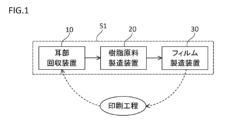
- FIG. 1 is a diagram illustrating a resource circulation system.
- FIG. 2 is a plan view illustrating an example of a printed film.
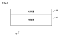
- FIG. 3 is a schematic diagram showing a cross section taken along line III-III in FIG. 2.
- FIG. 2 is a plan view showing a typical example of the ear portion recovery device;
- FIG. 2 is a front view showing a typical ear portion recovery device.
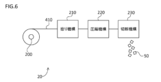
- FIG. 1 is a diagram showing a schematic configuration of a resin raw material production apparatus.
- FIG. 1 is a schematic diagram of a resource circulation system S1 that uses a film manufacturing method according to the present embodiment.
- a resin film with a printed design hereinafter also referred to as "printed film”
- the printed film is, for example, a heat-shrinkable film or packaging bag that can be used for food, beverages, medicines/medical products, cosmetics, toiletries, or industrial/agricultural products.
- the printed film 40 is a heat-shrinkable film before heat shrinking.
- the printed film 40 includes a product portion 400 and ear portions 410A, 410B.
- the ear portions 410 are provided at positions adjacent to both ends of the product portion 400 in the width direction.
- a pattern is printed on each of the product portion 400 and the ear portions 410.
- the pattern printed on the product portion 400 is also referred to as the "product portion pattern”
- the pattern printed on the ear portion 410 is also referred to as the "ear portion pattern”.
- the ratio of the area of the ear portion pattern to the area of the ear portion 410 is 70% or less, preferably 50% or less, more preferably 30% or less, and even more preferably 15% or less.
- the ratio of the area of the ear pattern to the area of the ear 410 is smaller than the ratio of the area of the product pattern to the area of the product 400.
- Product section 400 is used for packaging plastic containers, glass containers, paper containers, etc.
- Each of ear sections 410A, 410B is printed with information for checking the printing condition of product section 400. That is, ear section 410 is used for checking the printing condition of product section 400.
- Registration marks 412A and color control marks 416 are printed on ear section 410A.
- Registration marks 412B, slit lines 414, and color bars 418 are printed on ear section 410B.
- Printing on the film is done, for example, by using a gravure plate.
- the registration marks 412 are used to align the gravure plate when printing the design.
- the slit lines 414 are used when cutting the edge portions 410 from the printed film 40.
- the color control marks 416 are made up of multiple triangles and are used to align the color plates.
- the color control marks 416 include a triangle for each color used in printing.
- the color bars 418 are used to check the quality of the density of each printed color.
- the resource circulation system S1 includes an edge recovery device 10, a resin raw material manufacturing device 20, and a film manufacturing device 30.
- the edge recovery device 10 is configured to cut edge portions 410 from a printed film 40 and recover the cut edge portions 410.
- the resin raw material manufacturing device 20 is configured to manufacture a resin raw material by using the edge portions 410 recovered by the edge recovery device 10.
- the film manufacturing device 30 is configured to manufacture a film by using the resin raw material manufactured by the resin raw material manufacturing device 20.
- the film produced by the film production device 30 is printed again.
- the printed film 40 is produced again.
- the edge portions 410 contained in the produced printed film 40 are collected again by the edge portion collection device 10 and used to produce new film. Resource circulation is achieved by repeating this cycle.
- the film is manufactured by using the edge portion 410 of the product portion 400.
- the product portion 400 with a relatively large design printed thereon is not used to manufacture the film, and the ink forming the product portion design does not mix with the film, so a relatively high quality film can be manufactured even without removing the ink forming the product portion design.
- Fig. 3 is a schematic diagram showing a cross section taken along line III-III in Fig. 2.
- the printed film 40 includes a resin layer 42 and a printing layer 44.
- the printing layer 44 is composed of a coloring component such as ink that forms a pattern.
- the object to be packaged is placed on the printing layer 44 side. That is, when packaging is performed using the printed film 40, the printing layer 44 is located on the inside.
- An inner coat layer may be provided on the printing layer 44, and an overcoat layer may be provided on the resin layer 42.
- the resin layer 42 may be composed of a single layer, or may be composed of multiple laminated layers.
- the resin layer 42 may include a layer in which different types of resins are mixed, or may include multiple layers each containing a different type of resin.
- Each layer constituting the resin layer 42 may also contain components other than resin.
- Each layer may contain metal components such as aluminum, antiblocking agents, additives, etc. Examples of additives include heat stabilizers, antioxidants, ultraviolet absorbers, light stabilizers, lubricants, antistatic agents, flame retardants, antibacterial agents, and fluorescent whitening agents.
- Examples of the types of resin contained in each layer include polyolefin resins, polystyrene resins, polyamide resins, and polyester resins.
- Examples of polyolefin resins include polypropylene, polyethylene, and cyclic polyolefin resins.
- Examples of polystyrene resins include styrene-butadiene copolymers, styrene-isoprene copolymers, styrene-isoprene-butadiene copolymers, styrene-acrylic copolymers, acrylonitrile-butadiene-styrene copolymers, and acrylonitrile-styrene copolymers.
- polyamide resins include aliphatic polyamides such as nylon 6 resins, nylon 66 resins, and nylon 12 resins, aromatic polyamides, amorphous polyamides, and polyamide elastomers.
- polyester resins include those obtained by condensation polymerization of a dicarboxylic acid component and a diol component.
- the type of the dicarboxylic acid component is not particularly limited, and examples thereof include terephthalic acid, o-phthalic acid, isophthalic acid, succinic acid, adipic acid, sebacic acid, azelaic acid, octyl succinic acid, cyclohexanedicarboxylic acid, naphthalenedicarboxylic acid, fumaric acid, maleic acid, itaconic acid, decamethylene carboxylic acid, anhydrides thereof, and lower alkyl esters thereof.
- the type of the diol component is also not particularly limited, and examples thereof include ethylene glycol, 1,3-propanediol, 1,4-butanediol, diethylene glycol, 1,5-pentanediol, 1,6-hexanediol, dipropylene glycol, triethylene glycol, tetraethylene glycol, 1,2-propanediol, 1,3-butanediol, 2,3-butanediol, neopentyl glycol (2,2-dimethylpropane-1,3-diol), 1,2-hexanediol, 2,5- Examples include aliphatic diols such as hexanediol, 2-methyl-2,4-pentanediol, 3-methyl-1,3-pentanediol, 2-ethyl-1,3-hexanediol, and polytetramethylene ether glycol; alicyclic dio
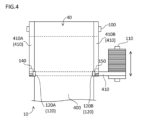
- Fig. 4 is a plan view showing the selvage collecting device 10.
- Fig. 5 is a front view showing the selvage collecting device 10.
- the selvage collecting device 10 includes an unwinding roll 100, a take-up roll 110, cutting mechanisms 120A and 120B, and transport rolls 140, 150, 160, and 170.
- the unwinding roll 100 is attached with a roll of printed film 40.
- the unwinding roll 100 is configured to unwind the printed film 40 by rotating.
- the cutting mechanisms 120A and 120B are configured to cut the tabs 410A and 410B from the printed film 40, respectively.
- the cutting mechanisms 120A and 120B are provided near the transport rolls 140 and 150, respectively.
- Each of the cutting mechanisms 120A and 120B has, for example, a rotating blade, and cuts the tabs 410 from the printed film 40 by rotating the rotating blade.
- the cutting mechanism 120B also has a sensor that detects the slit lines 414 (see FIG. 2), and the cutting mechanisms 120A and 120B are positioned in the width direction based on the detection results of the sensor.
- the product part 400 manufactured by cutting out the ears 410A and 410B is wound up by a winding roll (not shown). Meanwhile, the ears 410A and 410B are transported downward by the transport rolls 140 and 150, respectively. The ears 410 are then transported downstream by the transport rolls 160 and 170, and are wound up by the winding roll 110.
- the winding roll 110 repeatedly travels back and forth in a direction perpendicular to the transport direction of the ears 410 after passing through the transport rolls 160 and 170 in a plan view (traverse). This forms a winding body of the ears 410. In this winding body, the ears 410 are wound circumferentially around a cylindrical winding core.
- the ear portion recovery device 10 in the ear portion recovery device 10, the ear portion 410 cut from the printed film 40 is wound up, thereby recovering the ear portion 410. Therefore, the ear portion recovery device 10 can efficiently recover the ear portion 410. It can also facilitate the use of the ear portion 410 in subsequent processes.
- the ear portions 410A, 410B cut from both ends of the product portion 400 are wound up on a common winding roll 110, thereby recovering the ear portions 410A, 410B. Therefore, the ear portion recovery device 10 can more efficiently recover the ear portions 410.
- Configuration of resin raw material manufacturing equipment> 6 is a diagram showing a schematic configuration of the resin raw material production apparatus 20. As shown in FIG. 6, the resin raw material production apparatus 20 includes an unwinding roll 200, a twisting mechanism 210, a compression mechanism 220, and a cutting mechanism 230.
- a winding body of the ear portion 410 is attached to the unwinding roll 200.
- the unwinding roll 200 is configured to unwind the ear portion 410 by rotating.
- the ear portion 410 unwound by the unwinding roll 200 still has the ear portion pattern printed on it. In other words, when the ear portion 410 is turned into raw material, the ear portion pattern is not removed (de-inked).
- the twisting mechanism 210 has a rotation axis parallel to the transport path of the ear portion 410, and is configured to twist the ear portion 410 by rotating.
- the compression mechanism 220 is configured to compress the ear portion 410 twisted by the twisting mechanism 210, and to densify the ear portion 410.
- the cutting mechanism 230 is configured to cut the ear portion 410 compressed by the compression mechanism 220. In this way, the pellet-shaped resin raw material 50 is produced.
- the ear portion 410 is processed into the resin raw material 50 without going through a melting process. Therefore, the resin raw material manufacturing device 20 can suppress deterioration of the resin raw material 50 caused by thermal history.
- Fig. 7 is a diagram showing a schematic configuration of the film production apparatus 30. As shown in Fig. 7, the film production apparatus 30 includes a T-die 300, cast rolls 310 and 320, a longitudinal stretching machine 340, and a transverse stretching machine 350.
- the T-die 300 includes a T-die body 301 and raw material input sections 330, 331, and 332.
- the resin layer 42 (see FIG. 3) is composed of three layers.
- the central layer (middle layer) of the three layers constituting the resin layer 42 is composed of raw material input into the raw material input section 331.
- the raw material input section 331 is input with the resin raw material.
- at least one of virgin raw material, recycled raw material, and biomass raw material may be input into the raw material input section 331.
- the virgin raw material refers to a raw material that has never been used in film production.
- the recycled raw material includes at least one of raw material regenerated by chemical recycling, raw material regenerated by mechanical recycling, and raw material regenerated by material recycling.
- the resin raw material 50 is not input into each of the raw material input sections 330 and 332.
- the proportion of resin raw material 50 in the raw materials fed into raw material feed section 331 is 45 wt% or less, preferably 30 wt% or less, more preferably 15 wt% or less, even more preferably 7.5 wt% or less, and especially preferably 4.5 wt% or less.
- the proportion of resin raw material 50 in all raw materials fed into raw material feed sections 330, 331, and 332 is 30 wt% or less, preferably 20 wt% or less, more preferably 10 wt% or less, even more preferably 5 wt% or less, and especially preferably 3 wt% or less.
- the T-die body 301 is configured to co-extrude the raw materials fed through the raw material feed sections 330, 331, and 332, thereby fusing the molten raw materials fed into each raw material feed section to form a single integrated film (molten material).
- the cast rolls 310 and 320 are configured to cool the extruded molten material and send it downstream.
- the longitudinal stretching machine 340 stretches the molten material cooled by the cast rolls 310 and 320 in the MD (Machine Direction).
- the transverse stretching machine 350 stretches the film that has been stretched in the MD in the TD (Transverse Direction).
- the film 60 that has been subjected to various stretching processes is wound up by a winding roll (not shown) located downstream.
- a roll of film 60 is produced through the manufacturing process in the film manufacturing device 30.
- the haze value of the film 60 is 16% or less, preferably 14% or less, more preferably 10% or less, even more preferably 7% or less, and particularly preferably 6.5% or less.
- L* in the L*a*b* color space is, for example, 89 or more and 93.6 or less
- a* is, for example, -1.8 or more and -0.22 or less
- b* is, for example, 4.2 or more and 9.5 or less.
- the resin raw material 50 and the film 60 recycled from it may contain (meth)acrylic ester resin.
- the (meth)acrylic ester resin is often applied as an overcoat to the surface of the printed layer 44 included in the printed film 40.
- the (meth)acrylic ester resin may also be included in the ink constituting the printed layer 44 included in the printed film 40.
- the (meth)acrylic ester resin is generally not used as the main component of the film because it may reduce the transparency of the film. Therefore, when the resin raw material 50 contains a (meth)acrylic ester resin, it is understood that such a resin raw material is a recycled product.
- the printed film 40 has a layer containing a (meth)acrylic ester resin other than the overcoat layer and the printed layer 44, it is understood that such a printed film 40 is a recycled product.
- the content of the (meth)acrylic ester resin in the film 60 is 0.7 wt % or less.
- Film manufacturing procedure Fig. 8 is a flow chart showing the manufacturing procedure of the film 60 in the resource circulation system S1.
- the edge portion recovery device 10 cuts the edge portions 410 from the printed film 40 (step S100).
- the edge portion recovery device 10 winds up the cut edge portions 410 to form a roll of the edge portions 410 (step S110).
- the resin raw material manufacturing device 20 uses the edge portions 410 unwound from the roll to manufacture the resin raw material 50 (step S120).
- the film manufacturing device 30 uses the resin raw material 50 to manufacture the film 60 (step S130).
- the film 60 is manufactured by using the edge portion 410 of the printed film 40.
- the product portion 400 on which the product portion design is printed is not used in the manufacture of the film 60, and the ink that forms the product portion design does not mix with the film 60, so that a relatively high quality film 60 can be manufactured even if the ink that forms the product portion design is not removed.
- the ratio of the area of the ear pattern to the area of the ear 410 is smaller than the ratio of the area of the product pattern to the area of the product 400, and the amount of ink mixed into the film 60 is relatively small, so a relatively high quality film 60 can be produced even without removing the ink that forms the ear pattern.
- the selvages 410A and 410B are wound up by the common winding roll 110.
- the selvages 410A and 410B do not necessarily have to be wound up by the common winding roll 110.
- the selvages 410A and 410B may be wound up by different winding rolls.
- the resin raw material 50 is charged at a predetermined rate to the raw material charging section 331 in the film manufacturing apparatus 30.
- the rate of the resin raw material 50 charged to the raw material charging section 331 may be adjusted, for example, at a predetermined cycle.
- the color measurement of the resin raw material 50 or film 60 to be manufactured may be performed at a predetermined cycle, and the amount of the resin raw material 50 used in manufacturing the film 60 may be adjusted based on the measurement result.
- the charging rate of the resin raw material 50 may be reduced.
- the charging rate of the resin raw material 50 may be reduced.
- the ear 410 is twisted as it is by the twisting mechanism 210 in the resin raw material manufacturing apparatus 20.
- the ear 410 does not necessarily have to be twisted as it is.
- a cutting mechanism for cutting the ear 410 into even thinner pieces may be provided between the unwinding roll 200 and the twisting mechanism 210.
- the ear 410 unwound by the unwinding roll 200 may be cut into even thinner pieces by the cutting mechanism, and the cut ear 410 may be twisted by the twisting mechanism 210. This makes it easier to twist the ear 410.
- the ears 410 are processed into a resin raw material by using the resin raw material manufacturing device 20.
- the method of converting the ears 410 into a resin raw material is not limited to this.
- the ears 410 collected by the ear recovery device 10 may be finely cut to produce a fluff-like resin raw material.
- strands may be formed by melt extrusion, and pellet-like resin raw material may be produced by cutting the strands with a pelletizer.
- the ears 410 are processed by using the resin raw material manufacturing device 20, and the processed ears 410 are melt extruded to form strands, and pellet-like resin raw material may be produced by cutting the strands with a pelletizer.
- the films of the reference example and the examples 1-6 were manufactured.
- the film of the reference example was manufactured without using the above-mentioned resin raw material 50.
- the films of the examples 1-6 were manufactured using the above-mentioned resin raw material 50.
- the ears 410 printed ears
- the ratio of the area of the ear pattern to the area of the ear 410A was 3%
- the ratio of the area of the ear pattern to the area of the ear 410B was 19%.
- the above-mentioned ear recovery device 10 was used to form a roll of the printed ears, and the resin raw material 50 was manufactured using the resin raw material manufacturing device 20.
- the resin layer of the printed ears was composed of polyester-based resin/polystyrene-based resin/polyester-based resin.
- the polyester-based resin was a polyester-based resin composed of a dicarboxylic acid component and a diol component
- the polystyrene-based resin was a styrene-butadiene copolymer.
- the thickness of the surface layer the thickness of the intermediate layer: the thickness of the back layer was 1:5:1 to 1:8:1.
- the raw material composition that makes up each layer was fed into an extruder with a barrel temperature of 160-200°C, extruded from a multi-layer die at 200°C into a three-layered sheet, and cooled and solidified by a take-up roll at 50°C. Next, it was stretched at a stretch ratio of 3.5 times in a tenter stretching machine with a preheating zone of 102°C, a stretching zone of 89-91°C, and a heat setting zone of 86°C, and then taken up by a winding machine to produce a film in which the direction perpendicular to the main shrinkage direction is the MD and the main shrinkage direction is the TD.
- the front and back layers were each composed of polyester-based resin (polyester-based resin composed of a dicarboxylic acid component and a diol component).
- polyester-based resin composed of a dicarboxylic acid component and a diol component.
- the weight percentage concentration of the polyester-based resin was 100 wt%.
- the middle layer of the film of the Reference Example was composed of polystyrene-based resin (styrene-butadiene copolymer). In the middle layer of the film of the Reference Example, the weight percentage concentration of the polystyrene-based resin was 100 wt%.
- the middle layer of each of the films of Examples 1-6 was composed of polystyrene-based resin (styrene-butadiene copolymer) and a printed edge.
- polystyrene-based resin styrene-butadiene copolymer
- the weight percentage concentrations of the polystyrene-based resin and the printed edge were different from each other.
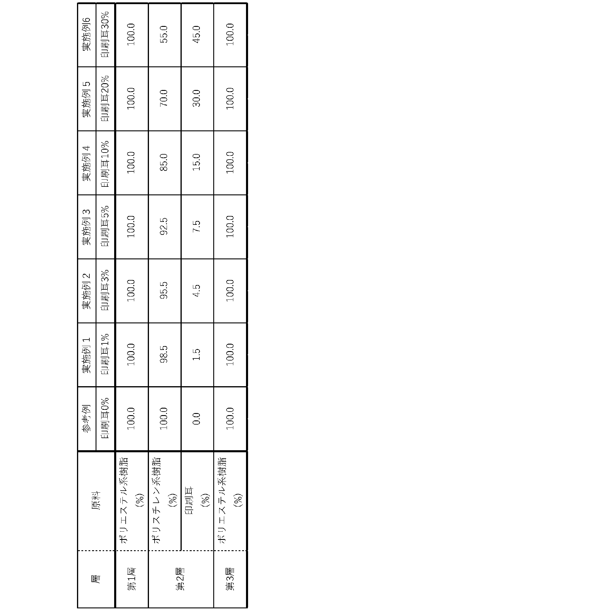
- the blending ratio of the raw materials in each layer of each film of the Reference Example and Examples 1-6 was as shown in Table 1 below.
- Young's modulus> A sample of 250 mm in MD ⁇ 5 mm in TD was cut out from the film. Young's modulus was measured at 23° C. using a Strograph VE-1D manufactured by Toyo Seiki Seisakusho Co., Ltd. according to a method in accordance with ASTM D882. The Young's modulus was measured using four samples, and the average value was calculated.
- the film was cut into a strip of width 10 mm x length 100 mm (the length direction was the same as the measurement direction of the film), and a line was drawn near the center of the length direction so that the distance between the marks was 40 mm to prepare a measurement sample.
- the measurement sample was measured for tensile strength and elongation using a tensile tester (Strograph VE1D, manufactured by Toyo Seiki Seisakusho Co., Ltd.) in accordance with a method conforming to JIS-K7127.
- the measurement atmosphere temperature was 23°C
- the distance between the chucks was 40 mm, the same as the marks, and the marked line was clamped with the chucks and pulled at a speed of 200 mm/min until the sample broke.
- the tensile elongation at break was calculated from the distance between the chucks before the test and the distance between the chucks at the time of break.
- the tensile strength at break was recorded. The test was performed four times, and the average value was calculated.
- each of the films of Examples 1-6 exhibited sufficient performance that was comparable to that of the Reference Examples in terms of wet heat shrinkage, Young's modulus, and tensile strength and elongation. Furthermore, each of the films of Examples 1-6 also exhibited haze, L*a*b*, and color difference at levels that were problem-free for practical use. In terms of appearance, the films of Examples 1, 2, and 3 were particularly excellent (A rating), followed by the films of Examples 4 and 5 (B rating), and the film of Example 6 was next best (C rating).
- 10 Selvage recovery device 20 Resin raw material manufacturing device, 30 Film manufacturing device, 40 Printed film, 42 Resin layer, 44 Printed layer, 50 Resin raw material, 60 Film, 100, 200 Unwinding roll, 110 Winding roll, 120 Cutting mechanism, 140, 150, 160, 170 Transport roll, 210 Twisting mechanism, 220 Compression mechanism, 230 Cutting mechanism, 300 T-die, 301 T-die body, 310, 320 Cast roll, 330, 331, 332 Raw material input section, 340 Vertical stretching machine, 350 Horizontal stretching machine, 400 Product section, 410 Selvage, 412 Registration mark, 414 Slit line, 416 Color control mark, 418 Color bar, S1 Resource circulation system.
Landscapes
- Chemical & Material Sciences (AREA)
- Engineering & Computer Science (AREA)
- Manufacturing & Machinery (AREA)
- Materials Engineering (AREA)
- Health & Medical Sciences (AREA)
- Chemical Kinetics & Catalysis (AREA)
- Medicinal Chemistry (AREA)
- Polymers & Plastics (AREA)
- Organic Chemistry (AREA)
- Extrusion Moulding Of Plastics Or The Like (AREA)
- Shaping By String And By Release Of Stress In Plastics And The Like (AREA)
Abstract
フィルムの製造方法は、印刷済フィルムの一部分を原料として用いる。印刷済フィルムは、第1図柄が印刷された製品部と、印刷済フィルムの幅方向における製品部の両端の少なくとも一方に隣接する位置に設けられた耳部とを含む。このフィルムの製造方法は、印刷済フィルムから耳部を裁断するステップと、印刷済フィルムから裁断された耳部を回収するステップと、回収された耳部を用いることによって樹脂原料を製造するステップと、樹脂原料を用いることによってフィルムを製造するステップとを含む。
Description
本発明は、フィルムの製造方法、巻取体及びフィルムに関する。
特許第6849141号公報(特許文献1)は、熱収縮性フィルムの製造方法を開示する。この熱収縮性フィルムの製造方法においては、包装資材が出発原料として用いられる(特許文献1参照)。
上記特許文献1に開示される熱収縮性フィルムの製造方法においては、包装資材が印刷層を有する場合に、インキの剥離処理が行なわれる。しかしながら、インキの剥離処理には多大なコストを要する。その結果、製造されるフィルムの価格が高くなる。
本発明は、このような問題を解決するためになされたものであって、その目的は、印刷済フィルムが原料として用いられ、かつ、印刷済フィルムにおけるインキの除去が行なわれない場合に比較的高品質なフィルムを製造可能なフィルムの製造方法、当該製造方法に用いられる巻取体、及び、当該製造方法によって製造されるフィルムを提供することである。
本発明のある局面に従うフィルムの製造方法は、印刷済フィルムの一部分を原料として用いる。印刷済フィルムは、第1図柄が印刷された製品部と、印刷済フィルムの幅方向における製品部の両端の少なくとも一方に隣接する位置に設けられた耳部とを含む。このフィルムの製造方法は、印刷済フィルムから耳部を裁断するステップと、印刷済フィルムから裁断された耳部を回収するステップと、回収された耳部を用いることによって樹脂原料を製造するステップと、樹脂原料を用いることによってフィルムを製造するステップとを含む。
このフィルムの製造方法においては、印刷済フィルムのうちの耳部を用いることによってフィルムが製造される。このフィルムの製造方法によれば、第1図柄が印刷された製品部がフィルムの製造に用いられず、第1図柄を形成するインキがフィルムに混じらないため、第1図柄を形成するインキの除去が行なわれなくても比較的高品質なフィルムを製造することができる。
このフィルムの製造方法においては、印刷済フィルムが、熱収縮前の状態の熱収縮フィルムであってもよい。
このフィルムの製造方法において、耳部には第2図柄が印刷されていてもよく、耳部の面積に対する第2図柄の面積の割合が、製品部の面積に対する第1図柄の面積の割合よりも小さくてもよい。
このフィルムの製造方法によれば、耳部の面積に対する第2図柄の面積の割合が製品部の面積に対する第1図柄の面積の割合よりも小さく、フィルムに混じるインキが比較的少量であるため、第2図柄を形成するインキの除去が行なわれなくても比較的高品質なフィルムを製造することができる。
このフィルムの製造方法においては、耳部の面積に対する第2図柄の面積の割合が70%以下であってもよい。
このフィルムの製造方法によれば、耳部の面積に対する第2図柄の面積の割合が70%以下であり、フィルムに混じるインキが少量であるため、第2図柄を形成するインキの除去が行なわれなくても比較的高品質なフィルムを製造することができる。
このフィルムの製造方法において、耳部を回収するステップにおいては、印刷済フィルムから裁断された耳部が巻き取られてもよい。
このフィルムの製造方法によれば、印刷済フィルムから裁断された耳部が巻き取られることによって耳部の回収が行なわれるため、耳部の回収を効率的に行なうことができる。
このフィルムの製造方法においては、耳部が、幅方向における製品部の両端の各々に隣接する位置に設けられていてもよく、耳部を裁断するステップにおいては、幅方向における製品部の両端の各々に隣接する位置に設けられた耳部が印刷済フィルムから裁断されてもよく、耳部を回収するステップにおいては、印刷済フィルムから裁断された各耳部が共通のロールによって巻き取られてもよい。
このフィルムの製造方法によれば、印刷済フィルムの両端部から裁断された各耳部が共通のロールで巻き取られることによって各耳部の回収が行なわれるため、耳部の回収を効率的に行なうことができる。
このフィルムの製造方法は、樹脂原料又はフィルムの色の測定を行なうステップと、測定の結果に基づいてフィルムの製造に用いる樹脂原料の量を調整するステップとをさらに含んでもよい。
このフィルムの製造方法によれば、樹脂原料又はフィルムの色の測定結果に基づいてフィルムの製造に用いられる樹脂原料の量が調整されるため、製造されるフィルムの品質を所定水準以上に維持することができる。
このフィルムの製造方法によって製造されるフィルムにおいては、ヘイズ値が16%以下であってもよい。
本発明の他の局面に従う巻取体は、印刷済フィルムの一部の巻取体である。印刷済フィルムは、図柄が印刷された製品部と、印刷済フィルムの幅方向における製品部の両端の少なくとも一方に隣接する位置に設けられた耳部とを含む。巻取体は、筒状の巻取りコアと、巻取りコアにおいて周方向に巻き付けられた耳部とを備える。
この巻取体においては、印刷済フィルムのうちの耳部が巻取りコアに巻き付けられている。この巻取体によれば、耳部が巻取りコアに巻き付けられているため、耳部を用いたフィルムの製造を容易にすることができる。
本発明の他の局面に従うフィルムは、印刷済フィルムの一部分が原料として用いられたフィルムである。印刷済フィルムは、第1図柄が印刷された製品部と、印刷済フィルムの幅方向における製品部の両端の少なくとも一方に隣接する位置に設けられた耳部とを含む。耳部には、第2図柄が印刷されている。耳部の面積に対する第2図柄の面積の割合は、製品部の面積に対する第1図柄の面積の割合よりも小さい。上記印刷済フィルムの一部分は耳部である。フィルムのヘイズ値は16%以下である。
本発明によれば、印刷済フィルムが原料として用いられ、かつ、印刷済フィルムにおけるインキの除去が行なわれない場合に比較的高品質なフィルムを製造可能なフィルムの製造方法、当該製造方法に用いられる巻取体、及び、当該製造方法によって製造されるフィルムを提供することできる。
以下、本発明の一側面に係る実施の形態(以下、「本実施の形態」とも称する。)について、図面を用いて詳細に説明する。なお、図中同一又は相当部分には同一符号を付してその説明は繰り返さない。また、各図面は、理解の容易のために、適宜対象を省略又は誇張して模式的に描かれている。
[1.概要]
近年、プラスチックの廃棄による海洋汚染等が世界的な問題となっている。このような問題に対処する手段として、資源循環が注目されている。
近年、プラスチックの廃棄による海洋汚染等が世界的な問題となっている。このような問題に対処する手段として、資源循環が注目されている。
図1は、本実施の形態に従うフィルムの製造方法を使用する資源循環システムS1を模式的に示す図である。図1を参照して、資源循環システムS1においては、図柄が印刷された樹脂製のフィルム(以下、「印刷済フィルム」とも称する。)がリサイクルされ、新たなフィルムが製造される。印刷済フィルムは、例えば、食品、飲料、医薬・医療品、化粧品、トイレタリー又は工業・農業用品等に利用可能な熱収縮フィルム又は包装袋等である。
図2は、印刷済フィルムの一例を模式的に示す平面図である。なお、この例において、印刷済フィルム40は、熱収縮前の状態の熱収縮フィルムである。図2に示されるように、印刷済フィルム40は、製品部400と、耳部410A,410Bとを含んでいる。耳部410は、幅方向における製品部400の両端の各々に隣接する位置に設けられている。製品部400及び耳部410の各々においては、図柄が印刷されている。以下、製品部400に印刷されている図柄を「製品部図柄」とも称し、耳部410に印刷されている図柄を「耳部図柄」とも称する。耳部410の面積に対する耳部図柄の面積の割合は、70%以下であり、50%以下であることが好ましく、30%以下であることがさらに好ましく、15%以下であることがより好ましい。耳部410の面積に対する耳部図柄の面積の割合は、製品部400の面積に対する製品部図柄の面積の割合よりも小さい。
製品部400は、プラスチック容器、ガラス容器及び紙容器等の包装に用いられる。耳部410A,410Bの各々においては、製品部400における印刷状態を確認するための情報等が印刷されている。すなわち、耳部410は、製品部400における印刷状態の確認等に用いられる。耳部410Aには、トンボ412A及びカラーコントロールマーク416が印刷されている。耳部410Bには、トンボ412B、スリット線414及びカラーバー418が印刷されている。
フィルムへの印刷は、例えば、グラビア版を用いることによって行なわれる。トンボ412は、図柄の印刷時におけるグラビア版の位置合わせに用いられる。スリット線414は、印刷済フィルム40から耳部410を裁断する際に用いられる。カラーコントロールマーク416は、複数の三角形で構成されており、各色版の見当合わせに用いられる。カラーコントロールマーク416は、印刷に用いられる各色の三角形を含んでいる。カラーバー418は、印刷された各色の濃度の品質確認に用いられる。
再び図1を参照して、資源循環システムS1は、耳部回収装置10と、樹脂原料製造装置20と、フィルム製造装置30とを含んでいる。耳部回収装置10は、印刷済フィルム40から耳部410を裁断し、裁断された耳部410を回収するように構成されている。樹脂原料製造装置20は、耳部回収装置10によって回収された耳部410を用いることによって樹脂原料を製造するように構成されている。フィルム製造装置30は、樹脂原料製造装置20によって製造された樹脂原料を用いることによってフィルムを製造するように構成されている。
フィルム製造装置30によって製造されたフィルムには、再び印刷が施される。すなわち、印刷済フィルム40が再び製造される。製造された印刷済フィルム40に含まれる耳部410は、再び耳部回収装置10によって回収され、新たなフィルムの製造に用いられる。このサイクルを繰り返すことによって資源循環が実現される。
このように、資源循環システムS1においては、製品部400のうちの耳部410を用いることによってフィルムが製造される。資源循環システムS1によれば、比較的大きい図柄が印刷された製品部400がフィルムの製造に用いられず、製品部図柄を形成するインキがフィルムに混じらないため、製品部図柄を形成するインキの除去が行なわれなくても比較的高品質なフィルムを製造することができる。
[2.構成]
<2-1.印刷済フィルムの構成>
図3は、図2のIII-III断面を模式的に示す図である。図3に示されるように、印刷済フィルム40は、樹脂層42と、印刷層44とを含んでいる。印刷層44は、例えば、図柄を形成するインキ等の着色成分によって構成される。本実施の形態においては、印刷層44側に包装対象が配置される。すなわち、印刷済フィルム40による包装が行なわれた場合に、印刷層44が内側に位置する。印刷層44上にはインナーコート層が設けられてもよく、樹脂層42上にはオーバーコート層が設けられてもよい。
<2-1.印刷済フィルムの構成>
図3は、図2のIII-III断面を模式的に示す図である。図3に示されるように、印刷済フィルム40は、樹脂層42と、印刷層44とを含んでいる。印刷層44は、例えば、図柄を形成するインキ等の着色成分によって構成される。本実施の形態においては、印刷層44側に包装対象が配置される。すなわち、印刷済フィルム40による包装が行なわれた場合に、印刷層44が内側に位置する。印刷層44上にはインナーコート層が設けられてもよく、樹脂層42上にはオーバーコート層が設けられてもよい。
樹脂層42は、単層で構成されてもよく、積層された複数の層で構成されてもよい。樹脂層42は、異なる種類の樹脂を混合した層を含んでいてもよいし、各々が異なる種類の樹脂を含有する複数の層を含んでいてもよい。また、樹脂層42を構成する各層は、樹脂以外の成分を含有していてもよい。各層は、アルミニウム等の金属成分、アンチブロッキング剤、添加剤等を含有し得る。添加剤の例としては、熱安定剤、酸化防止剤、紫外線吸収剤、光安定剤、滑剤、帯電防止剤、難燃剤、抗菌剤及び蛍光増白剤が挙げられる。
各層に含有される樹脂の種類の例としては、ポリオレフィン系樹脂、ポリスチレン系樹脂、ポリアミド系樹脂、ポリエステル系樹脂が挙げられる。ポリオレフィン系樹脂の例としては、ポリプロピレン系、ポリエチレン系、環状ポリオレフィン系樹脂が挙げられる。ポリスチレン系樹脂の例としては、スチレン-ブタジエン共重合体、スチレン-イソプレン共重合体、スチレン-イソプレン-ブタジエン共重合体、スチレン-アクリル系共重合体、アクリロニトリル-ブタジエン-スチレン共重合体、アクリロニトリル-スチレン共重合体が挙げられる。ポリアミド系樹脂の例としては、ナイロン6系樹脂、ナイロン66系樹脂、ナイロン12系樹脂等の脂肪族ポリアミド、芳香族ポリアミド、非晶質ポリアミド、ポリアミドエラストマーが挙げられる。ポリエステル系樹脂の例としては、ジカルボン酸成分とジオール成分とを縮重合させることにより得られるものが挙げられる。上記ジカルボン酸成分の種類は特に限定されず、テレフタル酸、o-フタル酸、イソフタル酸、コハク酸、アジピン酸、セバシン酸、アゼライン酸、オクチルコハク酸、シクロヘキサンジカルボン酸、ナフタレンジカルボン酸、フマル酸、マレイン酸、イタコン酸、デカメチレンカルボン酸、これらの無水物及び低級アルキルエステル等を例示することができる。上記ジオール成分の種類も特に限定されず、エチレングリコール、1,3-プロパンジオール、1,4-ブタンジオール、ジエチレングリコール、1,5-ペンタンジオール、1,6-ヘキサンジオール、ジプロピレングリコール、トリエチレングリコール、テトラエチレングリコール、1,2-プロパンジオール、1,3-ブタンジオール、2,3-ブタンジオール、ネオペンチルグリコール(2,2-ジメチルプロパン-1,3-ジオール)、1,2-ヘキサンジオール、2,5-ヘキサンジオール、2-メチル-2,4-ペンタンジオール、3-メチル-1,3-ペンタンジオール、2-エチル-1,3-ヘキサンジオール、ポリテトラメチレンエーテルグリコール等の脂肪族ジオール類、2,2-ビス(4-ヒドロキシシクロヘキシル)プロパン、2,2-ビス(4-ヒドロキシシクロヘキシル)プロパンのアルキレンオキサイド付加物、1,4-シクロヘキサンジオール、1,4-シクロヘキサンジメタノール等の脂環式ジオール類等を例示することができる。
<2-2.耳部回収装置の構成>
図4は、耳部回収装置10を模式的に示す平面図である。図5は、耳部回収装置10を模式的に示す正面図である。図4及び図5を参照して、耳部回収装置10は、巻出しロール100と、巻取りロール110と、裁断機構120A,120Bと、搬送ロール140,150,160,170とを含んでいる。
図4は、耳部回収装置10を模式的に示す平面図である。図5は、耳部回収装置10を模式的に示す正面図である。図4及び図5を参照して、耳部回収装置10は、巻出しロール100と、巻取りロール110と、裁断機構120A,120Bと、搬送ロール140,150,160,170とを含んでいる。
巻出しロール100には、印刷済フィルム40の原反が取り付けられる。巻出しロール100は、回転することによって印刷済フィルム40を巻き出すように構成されている。裁断機構120A,120Bは、それぞれ耳部410A,410Bを印刷済フィルム40から裁断するように構成されている。裁断機構120A,120Bは、それぞれ搬送ロール140,搬送ロール150の近傍に設けられている。裁断機構120A,120Bの各々は、例えば、回転刃を有し、回転刃を回転させることによって耳部410を印刷済フィルム40から裁断する。また、裁断機構120Bはスリット線414(図2参照)を検出するセンサを有しており、センサの検出結果に基づいて裁断機構120A,120Bの幅方向における位置決めが行なわれる。
耳部410A,410Bが裁断されることにより製造された製品部400は、不図示の巻取りロールによって巻き取られる。一方、耳部410A,410Bは、それぞれ搬送ロール140,150によって下方へ搬送される。その後、耳部410は、搬送ロール160,170によって下流へ搬送され、巻取りロール110によって巻き取られる。巻取りロール110は、搬送ロール160,170を経た後の耳部410の搬送方向と平面視において直交する方向において往復を繰り返す(トラバース)。これにより、耳部410の巻取体が形成される。この巻取体においては、筒状の巻取りコアにおいて周方向に耳部410が巻き付けられている。
このように、耳部回収装置10においては、印刷済フィルム40から裁断された耳部410が巻き取られることによって耳部410の回収が行なわれる。したがって、耳部回収装置10によれば、耳部410の回収を効率的に行なうことができる。また、後工程における耳部410の利用を容易にすることができる。
また、耳部回収装置10においては、製品部400の両端部から裁断された耳部410A,410Bが共通の巻取りロール110で巻き取られることによって耳部410A,410Bの回収が行なわれる。したがって、耳部回収装置10によれば、耳部410の回収をより効率的に行なうことができる。
<2-3.樹脂原料製造装置の構成>
図6は、樹脂原料製造装置20の構成を模式的に示す図である。図6に示されるように、樹脂原料製造装置20は、巻出しロール200と、捻り機構210と、圧縮機構220と、切断機構230とを含んでいる。
図6は、樹脂原料製造装置20の構成を模式的に示す図である。図6に示されるように、樹脂原料製造装置20は、巻出しロール200と、捻り機構210と、圧縮機構220と、切断機構230とを含んでいる。
巻出しロール200には、耳部410の巻取体が取り付けられる。巻出しロール200は、回転することによって耳部410を巻き出すように構成されている。巻出しロール200によって巻き出される耳部410には、耳部図柄が印刷されたままである。すなわち、耳部410を原料化するにあたって、耳部図柄の除去(脱墨)は行なわれない。
捻り機構210は、耳部410の搬送経路と平行な回転軸を有し、回転することによって耳部410を捻るように構成されている。圧縮機構220は、捻り機構210によって捻られた耳部410を圧縮し、耳部410を高密度化するように構成されている。切断機構230は、圧縮機構220によって圧縮された耳部410を切断するように構成されている。これにより、ペレット状の樹脂原料50が製造される。
樹脂原料製造装置20においては、溶融工程を経ることなく耳部410が樹脂原料50に加工される。したがって、樹脂原料製造装置20によれば、熱履歴に起因する樹脂原料50の劣化を抑制することができる。
<2-4.フィルム製造装置の構成>
図7は、フィルム製造装置30の構成を模式的に示す図である。図7に示されるように、フィルム製造装置30は、Tダイ300と、キャストロール310,320と、縦延伸機340と、横延伸機350とを含んでいる。
図7は、フィルム製造装置30の構成を模式的に示す図である。図7に示されるように、フィルム製造装置30は、Tダイ300と、キャストロール310,320と、縦延伸機340と、横延伸機350とを含んでいる。
Tダイ300は、Tダイ本体301と、原料投入部330,331,332とを含んでいる。この例においては、樹脂層42(図3参照)が3層で構成される。樹脂層42を構成する3層のうち中央の層(中間層)は、原料投入部331に投入される原料によって構成される。原料投入部331には、樹脂原料が投入される。原料投入部331には、樹脂原料50の他に、バージン原料、リサイクル原料及びバイオマス原料のうち少なくともいずれかが投入されてもよい。バージン原料とは、フィルム製造に一度も用いられていない原料のことをいう。また、リサイクル原料には、ケミカルリサイクルによって再生された原料、メカニカルリサイクルによって再生された原料、及び、マテリアルリサイクルによって再生された原料の少なくともいずれかが含まれる。また、この例において、原料投入部330,332の各々には、樹脂原料50が投入されない。
原料投入部331に投入される原料に占める樹脂原料50の割合は、45wt%以下であり、30wt%以下であることが好ましく、15wt%以下であることがより好ましく、7.5wt%以下であることがさらに好ましく、4.5wt%以下であることが特に好ましい。また、原料投入部330,331,332に投入される全原料に占める樹脂原料50の割合は、30wt%以下であり、20wt%以下であることが好ましく、10wt%以下であることがより好ましく、5wt%以下であることがさらに好ましく、3wt%以下であることが特に好ましい。
Tダイ本体301は、原料投入部330,331,332を介して投入された原料を共押出しすることによって、各原料投入部に投入された原料の溶融物同士を融着させて1枚の一体化したフィルム(溶融材料)とするように構成されている。キャストロール310,320は、押し出された溶融材料を冷却すると共に、下流へ送るように構成されている。縦延伸機340は、キャストロール310,320によって冷却された溶融材料に対してMD(Machine Direction)における延伸を施す。横延伸機350は、MDにおける延伸が施されたフィルムに対してTD(Transverse Direction)における延伸を施す。
各種延伸が施されたフィルム60は、下流に位置する巻取りロール(不図示)によって巻き取られる。フィルム製造装置30における製造工程を経てフィルム60の巻取体が製造される。
フィルム60のヘイズ値は、16%以下であり、14%以下であることが好ましく、10%以下であることがより好ましく、7%以下であることがさらに好ましく、6.5%以下であることが特に好ましい。また、フィルム60に関し、L*a*b*色空間におけるL*は、例えば、89以上、93.6以下であり、a*は、例えば、-(マイナス)1.8以上、-(マイナス)0.22以下であり、b*は、例えば、4.2以上、9.5以下である。
ところで、樹脂原料50及びこれから再生されるフィルム60は、(メタ)アクリル酸エステル系樹脂を含有することがある。(メタ)アクリル酸エステル系樹脂は、しばしば、印刷済フィルム40に含まれる印刷層44の表面にオーバーコートとして塗布される。また、(メタ)アクリル酸エステル系樹脂は、印刷済フィルム40に含まれる印刷層44を構成するインキに含まれ得る。一方で、(メタ)アクリル酸エステル系樹脂は、フィルムの透明性を低下させる虞があるため、一般に、フィルムの主成分としては使用されない。したがって、樹脂原料50が(メタ)アクリル酸エステル系樹脂を含有する場合、そのような樹脂原料は再生品であることが分かる。また、印刷済フィルム40が、オーバーコート層及び印刷層44以外に(メタ)アクリル酸エステル系樹脂を含有する層を有する場合、そのような印刷済フィルム40は、再生品であることが分かる。なお、フィルム60に含まれる(メタ)アクリル酸エステル系樹脂の含有率は、0.7wt%以下である。
[3.フィルムの製造手順]
図8は、資源循環システムS1におけるフィルム60の製造手順を示すフローチャートである。図8を参照して、耳部回収装置10は、印刷済フィルム40から耳部410を裁断する(ステップS100)。耳部回収装置10は、裁断された耳部410を巻き取ることによって、耳部410の巻取体を形成する(ステップS110)。樹脂原料製造装置20は、巻取体から巻き出された耳部410を用いることによって樹脂原料50を製造する(ステップS120)。フィルム製造装置30は、樹脂原料50を用いることによってフィルム60を製造する(ステップS130)。
図8は、資源循環システムS1におけるフィルム60の製造手順を示すフローチャートである。図8を参照して、耳部回収装置10は、印刷済フィルム40から耳部410を裁断する(ステップS100)。耳部回収装置10は、裁断された耳部410を巻き取ることによって、耳部410の巻取体を形成する(ステップS110)。樹脂原料製造装置20は、巻取体から巻き出された耳部410を用いることによって樹脂原料50を製造する(ステップS120)。フィルム製造装置30は、樹脂原料50を用いることによってフィルム60を製造する(ステップS130)。
[4.特徴]
以上のように、本実施の形態に従うフィルムの製造方法を使用する資源循環システムS1においては、印刷済フィルム40のうちの耳部410を用いることによってフィルム60が製造される。資源循環システムS1によれば、製品部図柄が印刷された製品部400がフィルム60の製造に用いられず、製品部図柄を形成するインキがフィルム60に混じらないため、製品部図柄を形成するインキの除去が行なわれなくても比較的高品質なフィルム60を製造することができる。
以上のように、本実施の形態に従うフィルムの製造方法を使用する資源循環システムS1においては、印刷済フィルム40のうちの耳部410を用いることによってフィルム60が製造される。資源循環システムS1によれば、製品部図柄が印刷された製品部400がフィルム60の製造に用いられず、製品部図柄を形成するインキがフィルム60に混じらないため、製品部図柄を形成するインキの除去が行なわれなくても比較的高品質なフィルム60を製造することができる。
また、資源循環システムS1によれば、耳部410の面積に対する耳部図柄の面積の割合が製品部400の面積に対する製品部図柄の面積の割合よりも小さく、フィルム60に混じるインキが比較的少量であるため、耳部図柄を形成するインキの除去が行なわれなくても比較的高品質なフィルム60を製造することができる。
[5.他の実施の形態]
上記実施の形態の思想は、以上で説明された実施の形態に限定されない。以下、上記実施の形態の思想を適用できる他の実施の形態の一例について説明する。
上記実施の形態の思想は、以上で説明された実施の形態に限定されない。以下、上記実施の形態の思想を適用できる他の実施の形態の一例について説明する。
<5-1>
上記実施の形態においては、耳部回収装置10において、耳部410A,410Bが共通の巻取りロール110によって巻き取られた。しかしながら、耳部410A,410Bは、必ずしも共通の巻取りロール110によって巻き取られなくてもよい。耳部410A,410Bは、互いに異なる巻取りロールによって巻き取られてもよい。
上記実施の形態においては、耳部回収装置10において、耳部410A,410Bが共通の巻取りロール110によって巻き取られた。しかしながら、耳部410A,410Bは、必ずしも共通の巻取りロール110によって巻き取られなくてもよい。耳部410A,410Bは、互いに異なる巻取りロールによって巻き取られてもよい。
<5-2>
また、上記実施の形態においては、フィルム製造装置30において、原料投入部331に予め定められた割合の樹脂原料50が投入された。しかしながら、原料投入部331に投入される樹脂原料50の割合は、例えば、所定周期で調整されてもよい。例えば、製造される樹脂原料50又はフィルム60の色測定が所定周期で行なわれ、測定結果に基づいてフィルム60の製造に用いる樹脂原料50の量が調整されてもよい。具体的には、製造される樹脂原料50又はフィルム60のL*a*b*のいずれかの値が予め定められた範囲から外れた場合に、樹脂原料50の投入割合が下げられてもよい。また、製造される樹脂原料50又はフィルム60のヘイズ値が予め定められた範囲から外れた場合に、樹脂原料50の投入割合が下げられてもよい。
また、上記実施の形態においては、フィルム製造装置30において、原料投入部331に予め定められた割合の樹脂原料50が投入された。しかしながら、原料投入部331に投入される樹脂原料50の割合は、例えば、所定周期で調整されてもよい。例えば、製造される樹脂原料50又はフィルム60の色測定が所定周期で行なわれ、測定結果に基づいてフィルム60の製造に用いる樹脂原料50の量が調整されてもよい。具体的には、製造される樹脂原料50又はフィルム60のL*a*b*のいずれかの値が予め定められた範囲から外れた場合に、樹脂原料50の投入割合が下げられてもよい。また、製造される樹脂原料50又はフィルム60のヘイズ値が予め定められた範囲から外れた場合に、樹脂原料50の投入割合が下げられてもよい。
<5-3>
また、上記実施の形態においては、樹脂原料製造装置20において、耳部410が捻り機構210によってそのまま捻られた。しかしながら、耳部410は、必ずしもそのまま捻られなくてもよい。例えば、巻出しロール200と捻り機構210との間に、耳部410をさらに細くに裁断する裁断機構が設けられてもよい。巻出しロール200によって巻き出された耳部410が、裁断機構によってさらに細くに裁断され、裁断後の耳部410が捻り機構210によって捻られてもよい。これにより、耳部410をより捻りやすくすることができる。
また、上記実施の形態においては、樹脂原料製造装置20において、耳部410が捻り機構210によってそのまま捻られた。しかしながら、耳部410は、必ずしもそのまま捻られなくてもよい。例えば、巻出しロール200と捻り機構210との間に、耳部410をさらに細くに裁断する裁断機構が設けられてもよい。巻出しロール200によって巻き出された耳部410が、裁断機構によってさらに細くに裁断され、裁断後の耳部410が捻り機構210によって捻られてもよい。これにより、耳部410をより捻りやすくすることができる。
また、上記実施の形態においては、樹脂原料製造装置20を用いることによって耳部410が樹脂原料に加工された。しかしながら、耳部410を樹脂原料化する方法はこれに限定されない。例えば、耳部回収装置10によって回収された耳部410を細かく切断することによってフラフ状の樹脂原料が製造されてもよい。また耳部回収装置10によって回収された耳部410の細断後、溶融押出しすることによってストランドを形成し、ストランドをペレタイザーで切断することによってペレット状の樹脂原料が製造されてもよい。また、例えば、樹脂原料製造装置20を用いることによって耳部410が加工され、加工後の耳部410を溶融押出しすることによってストランドを形成し、ストランドをペレタイザーで切断することによってペレット状の樹脂原料が製造されてもよい。
以上、本発明の実施の形態について例示的に説明した。すなわち、例示的な説明のために、詳細な説明及び添付の図面が開示された。よって、詳細な説明及び添付の図面に記載された構成要素の中には、課題解決のために必須でない構成要素が含まれることがある。したがって、それらの必須でない構成要素が詳細な説明及び添付の図面に記載されているからといって、それらの必須でない構成要素が必須であると直ちに認定されるべきではない。
また、上記実施の形態は、あらゆる点において本発明の例示にすぎない。上記実施の形態は、本発明の範囲内において、種々の改良や変更が可能である。例えば、いずれかの実施の形態の少なくとも一部の構成と、他のいずれかの実施の形態の少なくとも一部の構成とが組み合わされてもよい。すなわち、本発明の実施にあたっては、実施の形態に応じて具体的構成を適宜採用することができる。
以下、本発明の実施例について説明する。なお、本発明は以下の実施例に限定されない。
[1.参考例及び実施例]
参考例及び実施例1-6の各フィルムを製造した。参考例のフィルムは、上述の樹脂原料50を用いずに製造された。実施例1-6の各フィルムは、上述の樹脂原料50を用いて製造された。樹脂原料50の製造に用いられた耳部410(印刷耳)において、耳部410Aの面積に対する耳部図柄の面積の割合は3%であり、耳部410Bの面積に対する耳部図柄の面積の割合は19%であった。上述の耳部回収装置10を用いることによって印刷耳の巻取体が形成され、樹脂原料製造装置20を用いることによって樹脂原料50が製造された。なお、印刷耳の樹脂層の構成は、ポリエステル系樹脂/ポリスチレン系樹脂/ポリエステル系樹脂であった。ここで、ポリエステル系樹脂は、ジカルボン酸成分及びジオール成分からなるポリエステル系樹脂であり、ポリスチレン系樹脂は、スチレン-ブタジエン共重合体であった。印刷耳において、表層の厚み:中間層の厚み:裏層の厚み=1:5:1~1:8:1であった。
参考例及び実施例1-6の各フィルムを製造した。参考例のフィルムは、上述の樹脂原料50を用いずに製造された。実施例1-6の各フィルムは、上述の樹脂原料50を用いて製造された。樹脂原料50の製造に用いられた耳部410(印刷耳)において、耳部410Aの面積に対する耳部図柄の面積の割合は3%であり、耳部410Bの面積に対する耳部図柄の面積の割合は19%であった。上述の耳部回収装置10を用いることによって印刷耳の巻取体が形成され、樹脂原料製造装置20を用いることによって樹脂原料50が製造された。なお、印刷耳の樹脂層の構成は、ポリエステル系樹脂/ポリスチレン系樹脂/ポリエステル系樹脂であった。ここで、ポリエステル系樹脂は、ジカルボン酸成分及びジオール成分からなるポリエステル系樹脂であり、ポリスチレン系樹脂は、スチレン-ブタジエン共重合体であった。印刷耳において、表層の厚み:中間層の厚み:裏層の厚み=1:5:1~1:8:1であった。
各層を構成する原料組成物を、バレル温度が160~200℃の押出機に投入し、200℃の多層ダイスから3層構造のシート状に押出し、50℃の引き取りロールにて冷却固化した。次いで、予熱ゾーン102℃、延伸ゾーン89~91℃、熱固定ゾーン86℃のテンター延伸機内で延伸倍率3.5倍にて延伸した後、巻き取り機で巻き取ることにより、主収縮方向と直交する方向がMD、主収縮方向がTDとなるフィルムを製造した。
参考例及び実施例1-6の各フィルムにおいては、表裏層の各々がポリエステル系樹脂(ジカルボン酸成分及びジオール成分からなるポリエステル系樹脂)によって構成された。参考例及び実施例1-6の各フィルムの表裏層の各々において、ポリエステル系樹脂の重量パーセント濃度は100wt%であった。また、参考例のフィルムの中間層はポリスチレン系樹脂(スチレン-ブタジエン共重合体)で構成された。参考例のフィルムの中間層において、ポリスチレン系樹脂の重量パーセント濃度は100wt%であった。実施例1-6の各フィルムの中間層は、ポリスチレン系樹脂(スチレン-ブタジエン共重合体)及び印刷耳で構成された。実施例1-6においては、ポリスチレン系樹脂及び印刷耳の各々の重量パーセント濃度が互いに異なっていた。参考例及び実施例1-6の各フィルムの各層における原料の配合率は、以下の表1に示す通りであった。
[2.各種測定]
<2-1.ヘイズ値>
JIS Z7136に準拠した方法により、23℃の温度条件下で、ヘイズメーター(日本電色工業社製、NDH5000)を用いてヘイズ値を測定した。なお、ヘイズ値については、4つのサンプルを用いて測定し、その平均値を算出した。
<2-1.ヘイズ値>
JIS Z7136に準拠した方法により、23℃の温度条件下で、ヘイズメーター(日本電色工業社製、NDH5000)を用いてヘイズ値を測定した。なお、ヘイズ値については、4つのサンプルを用いて測定し、その平均値を算出した。
<2-2.L*a*b*値及び色差>
得られたフィルムについて、MD100mm×TD100mmの大きさのサンプルにカットし、色差計(コニカミノルタジャパン株式会社製 分光測色計CM-600d)を用いてL*a*b*表色系で表されるL*、a*、b*値の測定を行い(N=10)、平均値を算出した。そのL*、a*、b*値の平均値より、以下のCIE1976L*a*b*色差式を用いて色差(ΔE*ab)を計算した。
ΔE*ab=[(ΔL*)2+(Δa*)2+(Δb*)2]1/2
得られたフィルムについて、MD100mm×TD100mmの大きさのサンプルにカットし、色差計(コニカミノルタジャパン株式会社製 分光測色計CM-600d)を用いてL*a*b*表色系で表されるL*、a*、b*値の測定を行い(N=10)、平均値を算出した。そのL*、a*、b*値の平均値より、以下のCIE1976L*a*b*色差式を用いて色差(ΔE*ab)を計算した。
ΔE*ab=[(ΔL*)2+(Δa*)2+(Δb*)2]1/2
<2-3.湿熱収縮率>
フィルムから、MD100mm×TD100mmのサンプルを切り出した。得られたサンプルを100℃の沸騰水及び80℃の温水に10秒間浸漬させた後、サンプルを取り出し、15℃の水に5秒間浸漬した。そして、次式(1)に従ってMDの熱収縮率を算出し、次式(2)に従ってTDの熱収縮率を算出した。LMDは、熱収縮後のサンプルのMDの長さ(mm)であり、LTDは、熱収縮後のサンプルのTDの長さ(mm)である。なお、熱収縮率については、100℃、80℃の温度条件ごとに、2つのサンプルを用いて測定し、その平均値を算出した。
熱収縮率(%)={(100-LMD)/100}×100・・・(1)
熱収縮率(%)={(100-LTD)/100}×100・・・(2)
フィルムから、MD100mm×TD100mmのサンプルを切り出した。得られたサンプルを100℃の沸騰水及び80℃の温水に10秒間浸漬させた後、サンプルを取り出し、15℃の水に5秒間浸漬した。そして、次式(1)に従ってMDの熱収縮率を算出し、次式(2)に従ってTDの熱収縮率を算出した。LMDは、熱収縮後のサンプルのMDの長さ(mm)であり、LTDは、熱収縮後のサンプルのTDの長さ(mm)である。なお、熱収縮率については、100℃、80℃の温度条件ごとに、2つのサンプルを用いて測定し、その平均値を算出した。
熱収縮率(%)={(100-LMD)/100}×100・・・(1)
熱収縮率(%)={(100-LTD)/100}×100・・・(2)
<2-4.ヤング率>
フィルムから、MD250mm×TD5mmのサンプルを切り出した。ASTM D882に準拠した方法により、23℃の温度条件下で、東洋精機製作所社製ストログラフVE-1Dを用いてヤング率を測定した。なお、ヤング率については、4つのサンプルを用いて測定し、その平均値を算出した。
フィルムから、MD250mm×TD5mmのサンプルを切り出した。ASTM D882に準拠した方法により、23℃の温度条件下で、東洋精機製作所社製ストログラフVE-1Dを用いてヤング率を測定した。なお、ヤング率については、4つのサンプルを用いて測定し、その平均値を算出した。
<2-5.引張強伸度>
フィルムを幅10mm×長さ100mm(長さ方向は、フィルムの測定方向と同じ)の短冊状にカットし、長さ方向の中央付近に標線間40mmとなるように線を引いて測定サンプルとした。この測定サンプルについて、引張試験機(東洋精機製作所社製、ストログラフVE1D)を用いて、JIS-K7127に準拠した方法で引張破断強度及び伸度を測定した。なお、測定雰囲気温度は23℃、チャック間距離は標線と同じ40mmとし、標線の部分をチャックで挟み、速度200mm/minでサンプルが破断するところまで引っ張った。試験前のチャック間距離と破断したときのチャック間距離とから、引張破断伸度を求めた。そして、破断した時の引張破断強度を記録した。なお、試験回数は4回とし、その平均値を求めた。
フィルムを幅10mm×長さ100mm(長さ方向は、フィルムの測定方向と同じ)の短冊状にカットし、長さ方向の中央付近に標線間40mmとなるように線を引いて測定サンプルとした。この測定サンプルについて、引張試験機(東洋精機製作所社製、ストログラフVE1D)を用いて、JIS-K7127に準拠した方法で引張破断強度及び伸度を測定した。なお、測定雰囲気温度は23℃、チャック間距離は標線と同じ40mmとし、標線の部分をチャックで挟み、速度200mm/minでサンプルが破断するところまで引っ張った。試験前のチャック間距離と破断したときのチャック間距離とから、引張破断伸度を求めた。そして、破断した時の引張破断強度を記録した。なお、試験回数は4回とし、その平均値を求めた。
[3.測定結果]
各測定項目の測定結果は、以下の表2に示す通りであった。

各測定項目の測定結果は、以下の表2に示す通りであった。
実施例1-6の各フィルムにおいて、湿熱収縮率、ヤング率及び引張強伸度の各々に関し参考例に対して遜色のない十分な性能が得られた。また、実施例1-6の各フィルムにおいて、ヘイズ、L*a*b*及び色差についても実用上問題のない水準であった。見栄えとしては、実施例1,2,3の各フィルムが特に優れており(A評価)、実施例4,5の各フィルムが次に優れており(B評価)、実施例6のフィルムがその次に優れていた(C評価)。
10 耳部回収装置、20 樹脂原料製造装置、30 フィルム製造装置、40 印刷済フィルム、42 樹脂層、44 印刷層、50 樹脂原料、60 フィルム、100,200 巻出しロール、110 巻取りロール、120 裁断機構、140,150,160,170 搬送ロール、210 捻り機構、220 圧縮機構、230 切断機構、300 Tダイ、301 Tダイ本体、310,320 キャストロール、330,331,332 原料投入部、340 縦延伸機、350 横延伸機、400 製品部、410 耳部、412 トンボ、414 スリット線、416 カラーコントロールマーク、418 カラーバー、S1 資源循環システム。
Claims (10)
- 印刷済フィルムを原料として用いるフィルムの製造方法であって、
前記印刷済フィルムは、第1図柄が印刷された製品部と、前記印刷済フィルムの幅方向における前記製品部の両端の少なくとも一方に隣接する位置に設けられた耳部とを含み、
前記印刷済フィルムから前記耳部を裁断するステップと、
前記印刷済フィルムから裁断された前記耳部を回収するステップと、
回収された前記耳部を用いることによって樹脂原料を製造するステップと、
前記樹脂原料を用いることによってフィルムを製造するステップとを含む、フィルムの製造方法。 - 前記印刷済フィルムが、熱収縮前の状態の熱収縮フィルムである、請求項1に記載のフィルムの製造方法。
- 前記耳部には第2図柄が印刷されており、
前記耳部の面積に対する前記第2図柄の面積の割合が、前記製品部の面積に対する前記第1図柄の面積の割合よりも小さい、請求項1又は請求項2に記載のフィルムの製造方法。 - 前記耳部の面積に対する前記第2図柄の面積の割合が70%以下である、請求項3に記載のフィルムの製造方法。
- 前記耳部を回収するステップにおいては、前記印刷済フィルムから裁断された前記耳部が巻き取られる、請求項1又は請求項2に記載のフィルムの製造方法。
- 前記耳部が、前記幅方向における前記製品部の両端の各々に隣接する位置に設けられており、
前記耳部を裁断するステップにおいては、前記幅方向における前記製品部の両端の各々に隣接する位置に設けられた前記耳部が前記印刷済フィルムから裁断され、
前記耳部を回収するステップにおいては、前記印刷済フィルムから裁断された各耳部が共通のロールによって巻き取られる、請求項5に記載のフィルムの製造方法。 - 前記樹脂原料又は前記フィルムの色の測定を行なうステップと、
前記測定の結果に基づいて前記フィルムの製造に用いる前記樹脂原料の量を調整するステップとをさらに含む、請求項1又は請求項2に記載のフィルムの製造方法。 - 前記フィルムにおいては、ヘイズ値が16%以下である、請求項1又は請求項2に記載のフィルムの製造方法。
- 印刷済フィルムの一部の巻取体であって、
前記印刷済フィルムは、図柄が印刷された製品部と、前記印刷済フィルムの幅方向における前記製品部の両端の少なくとも一方に隣接する位置に設けられた耳部とを含み、
筒状の巻取りコアと、
前記巻取りコアにおいて周方向に巻き付けられた前記耳部とを備える、巻取体。 - 印刷済フィルムの一部分が原料として用いられたフィルムであって、
前記印刷済フィルムは、第1図柄が印刷された製品部と、前記印刷済フィルムの幅方向における前記製品部の両端の少なくとも一方に隣接する位置に設けられた耳部とを含み、
前記耳部には第2図柄が印刷されており、
前記耳部の面積に対する前記第2図柄の面積の割合は、前記製品部の面積に対する前記第1図柄の面積の割合よりも小さく、
前記印刷済フィルムの一部分は前記耳部であり、
前記フィルムのヘイズ値は16%以下である、フィルム。
Priority Applications (1)
| Application Number | Priority Date | Filing Date | Title |
|---|---|---|---|
| CN202480059357.9A CN121866292A (zh) | 2023-12-28 | 2024-11-25 | 膜的制造方法、卷绕体和膜 |
Applications Claiming Priority (2)
| Application Number | Priority Date | Filing Date | Title |
|---|---|---|---|
| JP2023223049 | 2023-12-28 | ||
| JP2023-223049 | 2023-12-28 |
Publications (1)
| Publication Number | Publication Date |
|---|---|
| WO2025142245A1 true WO2025142245A1 (ja) | 2025-07-03 |
Family
ID=96217429
Family Applications (1)
| Application Number | Title | Priority Date | Filing Date |
|---|---|---|---|
| PCT/JP2024/041578 Pending WO2025142245A1 (ja) | 2023-12-28 | 2024-11-25 | フィルムの製造方法、巻取体及びフィルム |
Country Status (2)
| Country | Link |
|---|---|
| CN (1) | CN121866292A (ja) |
| WO (1) | WO2025142245A1 (ja) |
Citations (5)
| Publication number | Priority date | Publication date | Assignee | Title |
|---|---|---|---|---|
| JPS5243884A (en) * | 1975-10-06 | 1977-04-06 | Mitsubishi Monsanto Chem | Process and apparatus for disposing waste of plastic belting edge |
| JP2002114435A (ja) * | 2000-10-11 | 2002-04-16 | Asano Laboratories Co Ltd | 樹脂成形シート縁部回収装置および樹脂成形シート縁部回収方法 |
| JP2008119831A (ja) * | 2006-11-08 | 2008-05-29 | Konica Minolta Opto Inc | 返材ペレットの製造方法 |
| JP2012131208A (ja) * | 2010-12-24 | 2012-07-12 | Nippon Zeon Co Ltd | フィルム耳の切取回収装置、長尺の光学フィルムの製造方法、及びフィルム耳の巻回体の製造方法 |
| JP2021187550A (ja) * | 2020-05-27 | 2021-12-13 | 三菱ケミカル株式会社 | 熱収縮性フィルムの製造方法 |
-
2024
- 2024-11-25 CN CN202480059357.9A patent/CN121866292A/zh active Pending
- 2024-11-25 WO PCT/JP2024/041578 patent/WO2025142245A1/ja active Pending
Patent Citations (5)
| Publication number | Priority date | Publication date | Assignee | Title |
|---|---|---|---|---|
| JPS5243884A (en) * | 1975-10-06 | 1977-04-06 | Mitsubishi Monsanto Chem | Process and apparatus for disposing waste of plastic belting edge |
| JP2002114435A (ja) * | 2000-10-11 | 2002-04-16 | Asano Laboratories Co Ltd | 樹脂成形シート縁部回収装置および樹脂成形シート縁部回収方法 |
| JP2008119831A (ja) * | 2006-11-08 | 2008-05-29 | Konica Minolta Opto Inc | 返材ペレットの製造方法 |
| JP2012131208A (ja) * | 2010-12-24 | 2012-07-12 | Nippon Zeon Co Ltd | フィルム耳の切取回収装置、長尺の光学フィルムの製造方法、及びフィルム耳の巻回体の製造方法 |
| JP2021187550A (ja) * | 2020-05-27 | 2021-12-13 | 三菱ケミカル株式会社 | 熱収縮性フィルムの製造方法 |
Also Published As
| Publication number | Publication date |
|---|---|
| CN121866292A (zh) | 2026-04-14 |
Similar Documents
| Publication | Publication Date | Title |
|---|---|---|
| KR100991638B1 (ko) | 열수축성 폴리에스테르계 필름, 및 그의 제조방법 | |
| KR101458662B1 (ko) | 라벨 | |
| US8632865B2 (en) | Heat-shrinkable polyester film | |
| CN100420568C (zh) | 热收缩性聚酯膜及其制造方法 | |
| WO2023013689A1 (ja) | 熱収縮性フィルム及びその製造方法 | |
| EP1698461A1 (en) | Heat shrinkable polyester film and heat shrinkable label | |
| EP3187334B1 (en) | Heat-shrinkable multilayer film and heat-shrinkable label | |
| CN111164135B (zh) | 热收缩性聚酯系薄膜卷 | |
| JP2023081941A (ja) | レーザー印字可能なフィルムおよびそれを用いた包装体 | |
| JP5993635B2 (ja) | 熱収縮性ポリエステル系フィルムおよびその製造方法 | |
| WO2025142245A1 (ja) | フィルムの製造方法、巻取体及びフィルム | |
| JP4909225B2 (ja) | 熱収縮性多層フィルム及び熱収縮性ラベル | |
| JP5082396B2 (ja) | 熱収縮性ポリエステル系フィルムおよびその製造方法 | |
| JP5818572B2 (ja) | 熱収縮性ポリエステル樹脂積層フィルム | |
| US10471755B2 (en) | Biaxially oriented polyester film | |
| CN101155689B (zh) | 热收缩性聚酯系薄膜及热收缩性标签 | |
| JP2020049895A (ja) | 熱収縮性多層フィルム | |
| JP7647768B2 (ja) | 熱収縮性ポリエステル系フィルム | |
| US12410288B2 (en) | Heat-shrinkable films and related systems and methods | |
| JP2007083734A (ja) | 熱収縮性ポリエステル系フィルムおよびポリエステル系樹脂の製造方法 | |
| WO2026058619A1 (ja) | リサイクルフィルム | |
| JP2009143605A (ja) | 包装体 | |
| JP5125017B2 (ja) | 熱収縮性ポリエステル系フィルムおよびその製造方法 | |
| WO2025177718A1 (ja) | 熱収縮性フィルム | |
| JP2001293779A (ja) | 乾熱収縮特性に優れる熱収縮性フィルム及びその使用 |
Legal Events
| Date | Code | Title | Description |
|---|---|---|---|
| 121 | Ep: the epo has been informed by wipo that ep was designated in this application |
Ref document number: 24912137 Country of ref document: EP Kind code of ref document: A1 |
|
| ENP | Entry into the national phase |
Ref document number: 2025566359 Country of ref document: JP Kind code of ref document: A |
|
| WWE | Wipo information: entry into national phase |
Ref document number: 2025566359 Country of ref document: JP |