WO2025142201A1 - 移植機 - Google Patents
移植機 Download PDFInfo
- Publication number
- WO2025142201A1 WO2025142201A1 PCT/JP2024/040958 JP2024040958W WO2025142201A1 WO 2025142201 A1 WO2025142201 A1 WO 2025142201A1 JP 2024040958 W JP2024040958 W JP 2024040958W WO 2025142201 A1 WO2025142201 A1 WO 2025142201A1
- Authority
- WO
- WIPO (PCT)
- Prior art keywords
- seedling
- lateral feed
- detection unit
- feed amount
- lateral
- Prior art date
- Legal status (The legal status is an assumption and is not a legal conclusion. Google has not performed a legal analysis and makes no representation as to the accuracy of the status listed.)
- Pending
Links
Images



Classifications
-
- A—HUMAN NECESSITIES
- A01—AGRICULTURE; FORESTRY; ANIMAL HUSBANDRY; HUNTING; TRAPPING; FISHING
- A01C—PLANTING; SOWING; FERTILISING
- A01C11/00—Transplanting machines
- A01C11/02—Transplanting machines for seedlings
Definitions
- the present invention relates to a transplanter.
- the lateral feed mechanism is equipped with a detection unit (referred to in the document as a "lateral feed sensor (104)") that detects the lateral feed amount of the seedling carrier.
- a detection unit referred to in the document as a "lateral feed sensor (104)
- the underside of the seedling carrier tends to be crowded with other mechanisms and equipment, especially in the area where the lateral feed mechanism is located.
- the detection unit is configured to always be linked to the lateral feed mechanism, there is a possibility that the detection unit may break down due to factors such as sliding wear. For this reason, the challenge is to find a way to detect the lateral feed amount with a simple configuration.
- the object of the present invention is to provide a transplanter that can detect the lateral feed amount of the lateral feed mechanism with a simple configuration.
- the transplanter according to the present invention is characterized by being equipped with a seedling carrier for placing a seedling mat thereon, a planting mechanism for removing the seedlings from the seedling mat and transplanting them into a field, a lateral feed mechanism for reciprocating the seedling carrier in the left and right directions in conjunction with the drive of the planting mechanism, a lateral feed amount change mechanism for changing the lateral feed amount, which is the speed at which the lateral feed mechanism reciprocates, and a detection unit for automatically detecting the lateral feed amount in conjunction with the movement of the lateral feed amount change mechanism.
- the detection unit automatically detects the lateral feed amount in conjunction with the movement of the lateral feed amount change mechanism.
- the detection unit moves only when the lateral feed amount change mechanism moves, and the risk of the detection unit suffering sliding wear is reduced compared to a configuration in which the detection unit is always linked to the lateral feed mechanism. This realizes a transplanter that is capable of detecting the lateral feed amount of the lateral feed mechanism with a simple configuration.
- a link-type operating tool is provided that is connected to the lateral feed amount change mechanism and receives manual operation for changing the lateral feed amount
- the detection unit is configured to detect the lateral feed amount that is changed based on the operation of the link-type operating device, It is preferable that the detection portion be disposed on the opposite side of the link-type operating tool from the lateral feed amount change mechanism.
- the detection unit detects the lateral feed amount that is changed based on the operation of the link-type operating device.
- the detection unit it is possible for the detection unit to detect the operation amount and operation position of the link-type operating device, and detect the operation amount and operation position as the lateral feed amount. This simplifies the configuration of the detection unit compared to a configuration in which the detection unit directly detects the operation of the lateral feed amount change mechanism. Also, the detection unit is provided on the opposite side of the link-type operating device to the lateral feed amount change mechanism.
- the detection unit it is easier to arrange the detection unit in a space that avoids interference with equipment such as the lateral feed mechanism and the lateral feed amount change mechanism, and other sensors, and maintenance is also easier, compared to a configuration in which the detection unit is provided on the side where the lateral feed mechanism and the lateral feed amount change mechanism are located.
- the lateral feed mechanism extends along the left-right direction of the aircraft body, and the detection unit is disposed in an area corresponding to the outer lateral end of the lateral feed mechanism in the left-right direction of the aircraft body.
- the rocking lever is connected to the lateral feed amount change mechanism via the first rod. Therefore, the lateral feed amount changes in response to the operator rocking the rocking lever.
- the detection unit is connected to the rocking lever via the second rod. This configuration enables the detection unit to detect the amount of operation and the operating position of the rocking lever, and detect the amount of operation and the operating position as the lateral feed amount.
- the lateral feed mechanism 22 described below drives the seedling carrier 14 to move back and forth from side to side, while each rotating case 12 is driven to rotate by the power transmitted from the transmission case 11, and each planting arm 15 alternately picks up seedlings from the bottom of the seedling carrier 14 and plants them on the surface of the field.
- the seedling planting device 10 is configured to plant seedlings using the planting arms 15 of multiple rotating cases 12.
- the seedling planting device 10 has a vertical feed mechanism 21 and a horizontal feed mechanism 22.
- the seedling planting device 10 is provided with a transmission mechanism 16.
- the machine body 1 is also provided with a PTO shaft (not shown) for transmitting power from an engine (not shown) to the seedling planting device 10.
- the transmission mechanism 16 receives the power of the engine from the PTO shaft via a universal joint.
- the lateral feed mechanism 22 drives the seedling carrier 14 back and forth in the left and right directions in conjunction with the drive of the planting arm 15.
- the lateral feed mechanism 22 has a lateral feed shaft 22a and a lateral feed member 22b.
- the lateral feed shaft 22a rotates by the power from the transmission mechanism 16.
- the lateral feed member 22b is attached to the lateral feed shaft 22a in a state in which it can rotate relative to the lateral feed shaft 22a and can slide relative to the lateral feed shaft 22a.
- the lateral feed member 22b is also connected to the seedling carrier 14.
- the lateral feed member 22b When the lateral feed shaft 22a rotates, the lateral feed member 22b is reciprocated in the direction in which the lateral feed shaft 22a extends by the spiral feed groove formed in the lateral feed shaft 22a. As a result, the seedling carrier 14 is reciprocated left and right. With this configuration, the seedling planting device 10 reciprocates the seedling carrier 14 left and right while performing seedling planting operations with the planting arm 15.
- the seedling planting device 10 is configured to move the seedling carrier 14 back and forth from side to side while performing the seedling planting operation. As the seedling carrier 14 moves back and forth from side to side, the position of the seedling carrier 14 relative to the machine body 1 changes in the left-right direction.
- the vertical feed mechanism 21 has a vertical feed shaft 21a, a first transmission arm 21b, a second transmission arm 21c, a passive arm 21d, a one-way clutch 21e, a drive shaft 21f, and a vertical feed belt 21g.
- the rice transplanter is for eight-row planting, so eight vertical feed belts 21g are provided.
- the number of vertical feed belts 21g may be seven or less, or nine or more, as long as it is the same as the number of loading surface sections 14a.
- the vertical feed shaft 21a rotates due to the power from the transmission mechanism 16.
- the first transmission arm 21b and the second transmission arm 21c are fixed to the vertical feed shaft 21a in a state where they cannot rotate relative to the vertical feed shaft 21a.
- the first transmission arm 21b is located to the left of the second transmission arm 21c.
- the passive arm 21d is connected to the drive shaft 21f via a one-way clutch 21e.
- the vertical feed belt 21g is configured to rotate in conjunction with the rotation of the drive shaft 21f.
- the passive arm 21d enters the rotation range of the first transmission arm 21b. This causes the first transmission arm 21b to come into contact with the passive arm 21d. The power of the vertical feed shaft 21a is then transmitted to the drive shaft 21f via the first transmission arm 21b, the passive arm 21d, and the one-way clutch 21e.
- the passive arm 21d enters the rotation range of the second transmission arm 21c. This causes the second transmission arm 21c to come into contact with the passive arm 21d. The power of the vertical feed shaft 21a is then transmitted to the drive shaft 21f via the second transmission arm 21c, the passive arm 21d, and the one-way clutch 21e.
- the drive shaft 21f rotates by the set rotation angle, and the vertical feed belt 21g rotates.
- the amount of rotation of the vertical feed belt 21g at this time corresponds to the specified feed distance.
- the vertical feed belt 21g is configured to come into contact with the seedling mat placed on the seedling carrier 14. Therefore, when the vertical feed belt 21g rotates, the seedling mat placed on the seedling carrier 14 moves downward by a preset feed distance.
- the feed distance when the vertical feed belt 21g rotates is the vertical feed amount per rotation in the vertical feed mechanism 21.
- the rice transplanter of this embodiment is equipped with a first seedling-out sensor 23 and a plurality of second seedling-out sensors 24.
- the first seedling-out sensor 23 and the plurality of second seedling-out sensors 24 are configured to detect a seedling-out state in which the vertical length of the seedling mat left on the seedling carrier 14 is equal to or less than a preset length.
- the first seedling-out sensor 23 and the plurality of second seedling-out sensors 24 are configured to detect a state in which the remaining seedling amount is equal to or less than a preset amount based on the vertical length of the seedlings of the seedling mat placed on the seedling carrier 14.
- the first seedling-out sensor 23 corresponds to a "seedling-out sensor".
- the first seedling out sensor 23 is provided in the second row of loading surface sections 14a from the right end of the machine.
- the second seedling out sensor 24 is provided in each loading surface section 14a. Note that the first seedling out sensor 23 is not limited to the second row of loading surface sections 14a from the right end of the machine, and may be provided in any loading surface section 14a. Furthermore, two or more first seedling out sensors 23 may be provided in any of the eight loading surface sections 14a.
- the first seedling out sensor 23 is provided on the upper part of the seedling carrying platform 14 in the vertical direction of the machine body.
- Each second seedling out sensor 24 is provided on the lower part of the seedling carrying platform 14 in the vertical direction of the machine body. In other words, the first seedling out sensor 23 is provided at a higher position than the second seedling out sensor 24.
- the first seedling cut sensor 23 has a support part 23A, a swinging part 23B, and a sensor part 23C.
- the swinging part 23B is supported by the support part 23A so that it can swing around the swing axis P1.
- a torsion spring is wound around the swing base end of the swinging part 23B. This biases the swinging part 23B to swing upward.
- the swinging part 23B has a mountain-shaped part in a side view. This mountain-shaped part is formed with a base end inclined part 23o, a top part 23p, and a sharp end part 23q.
- the first seedling out sensor 23 When the seedling mat steps on the first seedling out sensor 23, the first seedling out sensor 23 is displaced downward. As a result, the first seedling out sensor 23 is in a state where it does not detect out-of-seedling conditions, i.e., in a non-detection state. At this time, the sharp end 23q comes close to the sensor part 23C. Also, if the seedling mat is not stepping on the first seedling out sensor 23, the first seedling out sensor 23 swings upward due to the biasing force of the torsion spring. As a result, the first seedling out sensor 23 is in a detection state where it detects the out-of-seedling condition. At this time, the sharp end 23q moves away from the sensor part 23C.
- the first height position H1 is shown.
- the first seedling out sensor 23 located in that placement surface section 14a is in a non-detection state.
- the seedling top end position is the position of the top end of the seedling mat placed on the placement surface section 14a.
- the first seedling out sensor 23 detects the seedling out state.
- the length from the bottom end of the placement surface section 14a to the first height position H1 corresponds to the "first length". In other words, the first seedling out sensor 23 detects the seedling out state when the vertical length of the seedling mat left on the seedling placement platform 14 becomes equal to or less than the preset length (first length).
- the seedling mat slides downward from the upper end of the seedling carrier 14 along the loading surface section 14a, and the oscillating part 23B smoothly oscillates downward as the base end inclined part 23o comes into contact with the bottom of the seedling mat.
- This allows the first seedling out sensor 23 to switch from a non-detection state to a detection state of out-of-seedling without impeding the downward sliding of the seedling mat.
- This allows the first seedling out sensor 23 to switch from a non-detection state to a detection state of out-of-seedling without impeding the downward sliding of the seedling mat.
- the base end inclined part 23o has a gentler inclination than the sharp end part 23q, it is possible to detect the seedling mat over as much area of the oscillating part 23B as possible.
- the upper edge of the seedling mat passes over the top portion 23p and is transported downstream in the transport direction.
- the sharp end portion 23q is bent at a nearly right angle from the top portion 23p, and the upper edge of the seedling mat no longer comes into contact with the sharp end portion 23q immediately after passing the top portion 23p.
- the sharp end portion 23q no longer contacts the bottom of the seedling mat, and the oscillating portion 23B oscillates firmly upward due to the biasing force of the torsion spring.
- the first seedling-out sensor 23 can immediately detect the seedling-out state when the seedling top end position falls from the first height position H1 to the first height position H1 or below.
- the sharp end portion 23q since the sharp end portion 23q is located at the free end portion of the oscillating portion 23B, the sharp end portion 23q oscillates significantly around the oscillating axis P1. This allows the sensor unit 23C to reliably detect the presence or absence of the sharp end portion 23q, and the first seedling cut sensor 23 to reliably detect the presence or absence of the seedling mat.
- the second seedling out sensor 24 When the seedling mat steps on the second seedling out sensor 24, the second seedling out sensor 24 is displaced downwards. As a result, the first seedling out sensor 23 is in a state where it does not detect out-of-seedling conditions, i.e., in a non-detection state. Also, when the seedling mat does not step on the second seedling out sensor 24, the second seedling out sensor 24 is displaced upwards due to the biasing force of the biasing member. As a result, the second seedling out sensor 24 is in a detection state where it detects an out-of-seedling condition.
- the second height position H2 is shown.
- the second seedling out sensor 24 located in that placement surface section 14a is in a non-detection state. Also, when the seedling top end position in the placement surface section 14a is equal to or lower than the second height position H2, the second seedling out sensor 24 located in that placement surface section 14a detects the seedling out state.
- the seedling quantity adjustment unit 30 is configured to receive information from each of the first seedling cut sensor 23, the number acquisition unit 31, the length acquisition unit 32, the vertical feed detection unit 33, and the horizontal feed detection unit 34, and to control the seedling quantity change mechanism 25 to set or change the seedling quantity based on the information.
- the work information acquisition unit 35 acquires the lateral feed amount detected by the lateral feed detection unit 34 as work information. In addition to the lateral feed amount, the work information acquisition unit 35 also acquires the number of vertical feeds (vertical feed amount) detected by the vertical feed detection unit 33, the detection result of the first seedling out sensor 23, and the detection result of the second seedling out sensor 24 as work information. This work information is sent from the work information acquisition unit 35 to the notification unit 26.
- the number acquisition unit 31 and the length acquisition unit 32 may each be set, for example, on the operation panel of the driving unit 4, or may receive data from a remote management computer or mobile terminal via a wireless communication network.
- Examples of mobile terminals include smartphones and tablet computers.
- the length acquisition unit 32 is also configured to acquire the vertical dimension L2 (see FIG. 7) of the seedling mat before it is placed on the seedling carrier 14.
- the vertical dimension L1 (see FIG. 7) of a single seedling mat may be preset to a standard (e.g., 580 mm).
- the length acquisition unit 32 may be configured to acquire a known dimension L2, or may be configured to acquire the dimension L2 based on manual input.
- the vertical feed detection unit 33 is a switch-type sensor that detects the operation of the passive arm 21d, the drive shaft 21f, and the vertical feed belt 21g of the vertical feed mechanism 21 shown in FIG. 2.
- the lateral feed detection unit 34 is a swing-type potentiometer that is linked to the link-type operating device 40 (see FIG. 8).
- the lateral feed detection unit 34 detects the lateral feed amount of the lateral feed mechanism 22 by detecting the position of the swing lever 41 of the link-type operating device 40.
- the lateral feed amount is the speed at which the lateral feed mechanism 22 reciprocates.
- the number of lateral feeds is calculated by dividing the stroke amount of the reciprocating movement of the lateral feed mechanism 22 by the lateral feed amount. In other words, the lateral feed detection unit 34 detects the number of lateral feeds from when the vertical feed mechanism 21 is driven once to when it is driven again.
- step #01 the seedling quantity adjustment unit 30 judges whether or not a seedling mat has been put on the seedling carrier 14 before rice planting work begins. Putting in a seedling mat at this time means that seedling mats have been put in at least from a state where no seedling mats have been placed on the carrier surface section 14a where the first seedling out sensor 23 is located, to a state where the first seedling out sensor 23 does not detect a seedling out state. The seedling quantity adjustment unit 30 judges whether or not the first seedling out sensor 23 is in a state where it is not detecting a seedling out state. If the first seedling out sensor 23 detects a seedling out state (step #01: No), the judgment of step #01 is looped.
- the seedling harvesting amount adjustment unit 30 acquires the number of seedling mats to be used for planting seedlings in the field (the planned number of sheets to be used) from the number acquisition unit 31.
- the planned number of sheets to be used may be the planned number of sheets to be used in the entire field, or the planned number of sheets to be used per unit area (e.g., 10 ares).
- the seedling quantity adjustment unit 30 obtains the vertical dimension L2 of the seedling mat before it is placed on the seedling carrier 14 from the length acquisition unit 32.
- the dimension L2 is shown in Figure 7.
- Dimension L2 is derived from the dimension L1 of one seedling mat and the vertical number of seedling mats to be placed on the seedling carrier 14.
- the seedling carrier 14 is configured so that two seedling mats can be placed vertically. Therefore, dimension L2 is "dimension L1 x 2".
- the seedling quantity adjustment unit 30 acquires the crush amount ⁇ L from the length acquisition unit 32.
- the length acquisition unit 32 acquires the crush amount ⁇ L when the seedling mat is placed on the seedling tray 14 based on the difference between the vertical dimension L2 of the seedling mat before it is placed on the seedling tray 14 and the actual length L3 of the seedling mat placed on the seedling tray 14.
- the crush amount ⁇ L is "dimension L2 - length L3".
- step #06 the seedling harvesting amount adjustment unit 30 acquires the lateral feed amount (number of lateral feeds) of the lateral feed mechanism 22 detected by the lateral feed detection unit 34. This is because the seedling harvesting amount that should be set differs depending on the lateral feed amount.
- step #07 the seedling quantity adjustment unit 30 calculates the seedling quantity for the planting arm 15 as an initial setting based on the information acquired in the processing of steps #02 to #06. At this time, the seedling quantity adjustment unit 30 accurately sets the initial seedling quantity based on the crushing amount ⁇ L.
- step #08 the seedling removal amount adjustment unit 30 determines whether the first seedling out sensor 23 has detected a seedling out state. If the seedling removal amount has just been initially set in step #07, the determination in step #08 will be No. However, as the rice transplanter continues planting, the remaining amount of seedlings placed on the seedling placement platform 14 continues to decrease. Then, when the top end position of the seedlings falls below the first height position H1 in the placement surface section 14a where the first seedling out sensor 23 is located, the first seedling out sensor 23 detects the seedling out state (step #08: Yes).
- Figure 7 shows the vertical length L4 of the seedling mat when the top end position of the seedlings falls below the first height position H1.
- the vertical length (first length) of the seedling mat left on the seedling carrier 14 when the first seedling-out sensor 23 detects the seedling-out state is known as length L4 shown in Figure 7. Therefore, the seedling amount adjustment unit 30 calculates the difference between the actual vertical length L3 of the seedling mat when the seedling amount was initially set and the vertical length L4 of the seedling mat left on the seedling carrier 14 when the first seedling-out sensor 23 detects the seedling-out state. This difference is the consumed length L5, as shown in Figure 7. In step #09, the seedling amount adjustment unit 30 calculates the consumed vertical length L5 of the seedling mat.
- step #10 the seedling quantity adjustment unit 30 obtains from the vertical feed detection unit 33 the number of vertical feeds of the vertical feed mechanism 21 between the time when the seedling quantity is initially set in step #07 and the time when the first seedling out sensor 23 detects the seedling out state in step #08 (step #08: Yes).
- the calculated total vertical feed amount of the seedling mat will be longer than length L5. If the calculated total vertical feed amount of the seedling mat is longer than length L5, the planting arm 15 will pick up fewer seedlings than the target amount due to factors such as the seedling mat being hard.
- the seedling amount adjustment unit 30 controls the seedling amount change mechanism 25 so that the actual seedling amount of the planting arm 15 approaches the target seedling amount (step #12). Because the planting arm 15 takes out the seedlings from the lower end of the seedling carrier 14, the actual seedling amount of the planting arm 15 is related to the distance between the planting arm 15 and the lower end of the seedling carrier 14 when the planting arm 15 takes out the seedlings. Therefore, if the actual seedling amount is less than the target seedling amount, the seedling amount adjustment unit 30 controls the seedling amount change mechanism 25 so that the distance between the planting arm 15 and the lower end of the seedling carrier 14 when the planting arm 15 takes out the seedlings is shortened.
- the lateral feed detection unit 34 is configured to be located on the opposite side to the transmission mechanism 16 side across the link-type operating device 40, it is possible to assemble the lateral feed detection unit 34 in a space larger than the space between the rocking lever 41 and the transmission mechanism 16.
- a mudguard plate 52 is attached to the frame of the ground leveling rotor 50. Although not shown in FIG. 8, the wheels 2 are located in front of the mudguard plate 52. The mudguard plate 52 receives mud kicked up by the wheels 2 at its rear.
- the lateral feed detection unit 34 is located behind the mudguard plate 52. The lateral feed detection unit 34 overlaps with the mudguard plate 52 when viewed in the fore-and-aft direction of the aircraft. This makes it less likely that the lateral feed detection unit 34 will be hit by mud kicked up by the wheels 2.
- the lateral feed detection unit 34 is also located directly above the ground leveling float 13. This makes it less likely that the lateral feed detection unit 34 will be hit by mud from below.
- the link-type operating device 40 has a swing lever 41, and the swing lever 41 swings around the swing axis P2.
- the swing lever 41 may be a slide-type lever.
- the rocking lever 41 and the lateral feed detection unit 34 are each supported by the same support frame 14F.
- the rocking lever 41 may be supported by the support frame 14F
- the lateral feed detection unit 34 may be supported by a frame separate from the support frame 14F.
- the lateral feed detection unit 34 is a potentiometer. This is not limited to the embodiment, and for example, the lateral feed detection unit 34 may be a magnetic or optical linear gauge sensor that detects the position of the rocking lever 41, or may be a distance measuring device such as LiDAR that detects the position of the rocking lever 41. In addition, the lateral feed detection unit 34 may be a contact sensor that detects a predetermined lateral feed position.
- a riding rice transplanter is given as an example of a transplanter.
- the present invention is not limited to this embodiment, and the transplanter may be, for example, a vegetable transplanter, a pot seedling transplanter, or a walk-behind rice transplanter.
- Machine body 14 Seedling carrier 15: Planting arm (planting mechanism) 16: Transmission mechanism (transverse feed amount change mechanism) 22: lateral feed mechanism 26: notification unit 34: lateral feed detection unit (detection unit) 35: Work information acquisition section (acquisition section) 40: Link type operating device 41: Swing lever 42: First rod 44: Second rod P2: Swing axis of the swing lever
Landscapes
- Life Sciences & Earth Sciences (AREA)
- Soil Sciences (AREA)
- Environmental Sciences (AREA)
- Transplanting Machines (AREA)
Abstract
苗マットを載置する苗載台と、苗マットから苗を取り出して圃場に苗を移植する植付機構と、植付機構の駆動と連動して苗載台を左右方向に往復駆動する横送り機構22と、横送り機構22が往復駆動する速さである横送り量を変更する横送り量変更機構16と、横送り量変更機構16の動きに連動して横送り量を自動的に検出する検出部34と、が備えられている。
Description
本発明は、移植機に関する。
例えば日本国特開2010-213638号公報(特許文献1)に開示された移植機では、横送り機構に、苗載台の横送り量を検出する検出部(文献では「横送りセンサ(104)」)が備えられている。
ところで苗載台の裏面部分において、特に横送り機構の位置する箇所では他の機構や機器等で込み合いがちとなる。また、横送り機構は田植えの作業中には常に動作している部分であるため、検出部が常に横送り機構と連動する構成であると、検出部が摺動摩耗等の要因によって故障する可能性も考えられる。このため、いかに簡素な構成で横送り量を検出できるかが課題となる。
本発明の目的は、簡易な構成で横送り機構の横送り量を検出可能な移植機を提供することにある。
本発明による移植機には、苗マットを載置する苗載台と、前記苗マットから苗を取り出して圃場に苗を移植する植付機構と、前記植付機構の駆動と連動して前記苗載台を左右方向に往復駆動する横送り機構と、前記横送り機構が往復駆動する速さである横送り量を変更する横送り量変更機構と、前記横送り量変更機構の動きに連動して前記横送り量を自動的に検出する検出部と、が備えられていることを特徴とする。
本発明によると、検出部は横送り量変更機構の動きに連動して横送り量を自動的に検出する。この構成であれば、検出部は横送り量変更機構が動いた時だけに動き、検出部が常に横送り機構と連動する構成と比較して、検出部が摺動摩耗する虞が軽減される。これにより、簡易な構成で横送り機構の横送り量を検出可能な移植機が実現される。
本発明において、前記横送り量変更機構と連結され、前記横送り量を変更するための人為操作を受け付けるリンク式操作具が備えられ、
前記検出部は、前記リンク式操作具の操作に基づいて変更される前記横送り量を検出するように構成され、
前記検出部は、前記リンク式操作具を挟んで前記横送り量変更機構側と反対側に配置されていると好適である。
前記検出部は、前記リンク式操作具の操作に基づいて変更される前記横送り量を検出するように構成され、
前記検出部は、前記リンク式操作具を挟んで前記横送り量変更機構側と反対側に配置されていると好適である。
本構成によると、検出部がリンク式操作具の操作に基づいて変更される横送り量を検出する。この構成であれば、検出部がリンク式操作具の操作量や操作位置を検出し、当該操作量や操作位置を横送り量として検出する構成が可能となる。これにより、検出部が横送り量変更機構の動作を直接検出する構成と比較して、検出部の構成が簡素化される。また、検出部がリンク式操作具を挟んで横送り量変更機構側と反対側に設けられている。この構成であれば、横送り機構や横送り量変更機構の位置する側に検出部が設けられる構成と比較して、横送り機構や横送り量変更機構等の機器や、他のセンサ類等との干渉を回避したスペースに配置し易くなり、メンテナンスも容易になる。
本発明において、前記横送り量変更機構は機体の左右方向における中央領域に配置され、前記検出部は、前記横送り量変更機構に対して機体横外側の領域に配置されていると好適である。
本構成によって、検出部が作業者の手の届き易い位置に配置される。これにより、作業者による検出部の確認やメンテナンスが一層容易になる。
本発明において、前記横送り機構は機体の左右方向に沿って延ばされ、前記検出部は、機体の左右方向において前記横送り機構の機体横外側の端部に対応する領域に配置されていると好適である。
本構成であれば、他機器やセンサ類等との干渉を回避したスペースに検出部が配置され、かつ、検出部の位置が横送り機構の位置から余り離れない位置に配置される。これにより、検出部を含めた横送り機構の構成がコンパクトになり易い。
本発明において、前記横送り機構は機体の左右方向に沿って延ばされ、前記検出部は、機体の左右方向において前記横送り機構の機体横外側の端部よりも機体横外側の領域に配置されていると好適である。
本構成であれば、他機器やセンサ類等との干渉を回避したスペースに検出部が配置され、かつ、検出部の位置が作業者の手の届き易い位置に配置される。これにより、作業者による検出部の確認やメンテナンスが一層容易になる。
本発明において、前記横送り量変更機構と連結され、前記横送り量を変更するための人為操作を受け付けるリンク式操作具が備えられ、前記リンク式操作具に、前記人為操作を受け付ける揺動レバーと、前記揺動レバーに枢支連結されるとともに前記横送り量変更機構に連結された第一ロッドと、前記揺動レバーに枢支連結されるとともに前記検出部に連結された第二ロッドと、が備えられていると好適である。
本構成によると、揺動レバーが第一ロッドを介して横送り量変更機構と連結される。このため、作業者が揺動レバーを揺動することに応じて横送り量が変更される。そして、検出部が第二ロッドを介して揺動レバーと連結されている。この構成によって、検出部が揺動レバーの操作量や操作位置を検出し、当該操作量や操作位置を横送り量として検出する構成が可能となる。
本発明において、前記第二ロッドは、前記揺動レバーのうち、前記第一ロッドとの連結箇所よりも前記揺動レバーの揺動軸芯側の箇所に枢支連結されていると好適である。
本構成であれば、第二ロッドが第一ロッドとの連結箇所と揺動軸芯の箇所との間の箇所に連結される。この構成であれば、第二ロッドが第一ロッドとの連結箇所よりも遊端側に連結される構成と比較して、第二ロッドと他の機構等との干渉を回避しながら、第二ロッドを短くする構成が可能となる。
本発明において、前記検出部は、揺動式のポテンショメータであって、前記第二ロッドに枢支連結されていると好適である。
本構成によって、検出部の構成が一層簡素なものとなる。
本発明において、前記検出部によって検出された前記横送り量を作業情報として取得する取得部と、前記横送り量を含む前記作業情報を報知する報知部と、が備えられていると好適である。
本構成によって、オペレータ等は横送り量を容易に把握できる。
本発明の田植機を例示する実施形態を図1~図8に示す乗用型田植機(移植機の一例)に基づいて説明する。なお、図中に示す矢印「F」の方向を「機体の前方」、図中に示す矢印「B」の方向を「機体の後方」、図中に示す矢印「L」の方向を「機体の左方」、図中に示す矢印「R」の方向を「機体の右方」、図中に示す矢印「U」の方向を「機体の上方」、図中に示す矢印「D」の方向を「機体の下方」とする。
〔乗用型田植機の全体構造〕
図1,図2に示すように、田植機は、乗用型の機体1を備える。機体1は、四輪駆動形式の車輪2と、予備苗収納台3と、運転部4と、を備える。運転部4は機体1の後部領域に設けられ、作業者が搭乗する。なお、作業者の意味は運転者の意味も含む。予備苗収納台3の上方に、GNSS(グローバル・ナビゲーション・サテライト・システム、GPS、GLONASS、Galileo、BeiDou等)の受信装置5が備えられている。受信装置5が受信した測位信号に基づいて、自動走行と自動操舵との少なくとも一方が可能である。
図1,図2に示すように、田植機は、乗用型の機体1を備える。機体1は、四輪駆動形式の車輪2と、予備苗収納台3と、運転部4と、を備える。運転部4は機体1の後部領域に設けられ、作業者が搭乗する。なお、作業者の意味は運転者の意味も含む。予備苗収納台3の上方に、GNSS(グローバル・ナビゲーション・サテライト・システム、GPS、GLONASS、Galileo、BeiDou等)の受信装置5が備えられている。受信装置5が受信した測位信号に基づいて、自動走行と自動操舵との少なくとも一方が可能である。
機体1の後部に、苗植付装置10がリンク機構9を介して上下昇降可能なように支持されている。苗植付装置10は苗を圃場に植え付ける。また、苗植付装置10は、ローリングすることによって、機体1に対して左右揺動可能なように構成されている。
詳述はしないが、機体1には不図示のエンジンが搭載されている。エンジンの動力が、車輪2と苗植付装置10との夫々に伝達される。
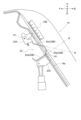
図1及び図2に示すように、苗植付装置10に、複数(本実施形態では四個)の伝動ケース11と、複数(本実施形態では八個)の回転ケース12と、整地フロート13と、苗載台14と、が備えられている。回転ケース12は、各伝動ケース11の後部の左側部及び右側部の夫々に回転可能に支持されている。夫々の回転ケース12の両端部に、一対のロータリ式の植付アーム15が備えられている。苗植付装置10に複数の整地フロート13が備えられ、整地フロート13は圃場の田面を整地する。苗載台14に苗マットが載置される。苗マットは植え付け用のマット状の苗である。なお、苗植付装置10に苗取量変更機構25(図5参照)が備えられている。苗取量変更機構25は、植付アーム15が苗載台14から取り出す苗取量を変更する機構である。植付アーム15は、『植付機構』の一例である。
図3に示すように、苗載台14は、機体左右方向に並ぶ複数(本実施形態では八個)の載置面区画14aを有する。各載置面区画14aの左右幅は、苗マットの左右幅に対応している。各載置面区画14aは、一条分の苗マットを載置可能に構成されている。これにより、苗載台14に八条分の苗マットが載置可能である。なお、載置面区画14aの個数は、七個以下でも良いし、九個以上でも良い。
後述の横送り機構22が苗載台14を左右に往復横送り駆動するとともに、各回転ケース12が伝動ケース11から伝達される動力によって回転駆動し、各植付アーム15が苗載台14の下部から交互に苗を取り出して圃場の田面に植え付ける。即ち、苗植付装置10は、複数の回転ケース12の植付アーム15で苗を植え付けるように構成されている。
〔縦送り機構及び横送り機構の構成〕
図2に示すように、苗植付装置10は、縦送り機構21及び横送り機構22を有する。苗植付装置10に伝動機構16が備えられている。また、機体1に、不図示のエンジンからの動力を苗植付装置10へ伝達するための不図示のPTO軸が備えられている。伝動機構16は、エンジンの動力を、ユニバーサルジョイントを介してPTO軸から受け取る。
図2に示すように、苗植付装置10は、縦送り機構21及び横送り機構22を有する。苗植付装置10に伝動機構16が備えられている。また、機体1に、不図示のエンジンからの動力を苗植付装置10へ伝達するための不図示のPTO軸が備えられている。伝動機構16は、エンジンの動力を、ユニバーサルジョイントを介してPTO軸から受け取る。
横送り機構22は、植付アーム15の駆動と連動して苗載台14を左右方向に往復駆動する。横送り機構22は、横送り軸22a及び横送り部材22bを有する。横送り軸22aは、伝動機構16からの動力によって回転する。
横送り部材22bは、横送り軸22aに対して相対回転可能な状態で、且つ、横送り軸22aに対してスライド可能な状態で、横送り軸22aに取り付けられている。また、横送り部材22bは、苗載台14に連結されている。
そして、横送り軸22aが回転すると、横送り部材22bは、横送り軸22aに形成された螺旋送り溝によって、横送り軸22aの延びる方向に往復移送される。これにより、苗載台14は、左右に往復移送される。この構成によって、苗植付装置10は、植付アーム15で苗植付動作を行いながら、苗載台14を左右に往復移送する。
即ち、苗植付装置10は、苗植付動作を行いながら苗載台14を左右に往復移送するように構成されている。苗載台14が左右に往復移送されることによって、機体1に対する苗載台14の位置が、左右方向に変化する。
また、図2に示すように、縦送り機構21は、縦送り軸21a、第一伝動アーム21b、第二伝動アーム21c、受動アーム21d、ワンウェイクラッチ21e、駆動軸21f、縦送りベルト21gを有する。
本実施形態においては、田植機は八条植えであるため、八個の縦送りベルト21gが備えられている。なお、縦送りベルト21gの個数は、載置面区画14aの個数と同じであれば、七個以下でも良いし、九個以上でも良い。
縦送り軸21aは、伝動機構16からの動力によって回転する。また、第一伝動アーム21b及び第二伝動アーム21cは、縦送り軸21aに対して相対回転不能な状態で、縦送り軸21aに固定されている。第一伝動アーム21bは、第二伝動アーム21cよりも左側に位置している。
受動アーム21dは、ワンウェイクラッチ21eを介して、駆動軸21fに連結されている。そして、縦送りベルト21gは、駆動軸21fの回転と連動して回動するように構成されている。
苗載台14が左のストロークエンドに到達すると、受動アーム21dが、第一伝動アーム21bの回転域に入る。これにより、第一伝動アーム21bが受動アーム21dに接当する。そして、縦送り軸21aの動力が、第一伝動アーム21b、受動アーム21d、ワンウェイクラッチ21eを介して、駆動軸21fに伝達される。
その結果、駆動軸21fが設定回転角だけ回転するとともに、縦送りベルト21gが回動する。このときの縦送りベルト21gの回動量は、所定の送り距離に相当する回動量である。
また、苗載台14が右のストロークエンドに到達すると、受動アーム21dが、第二伝動アーム21cの回転域に入る。これにより、第二伝動アーム21cが受動アーム21dに接当する。そして、縦送り軸21aの動力が、第二伝動アーム21c、受動アーム21d、ワンウェイクラッチ21eを介して、駆動軸21fに伝達される。
その結果、駆動軸21fが設定回転角だけ回転するとともに、縦送りベルト21gが回動する。このときの縦送りベルト21gの回動量は、所定の送り距離に相当する回動量である。
縦送りベルト21gは、苗載台14に載置されている苗マットに接当するように構成されている。そのため、縦送りベルト21gが回動することによって、苗載台14に載置されている苗マットは、予め設定された送り距離だけ下側へ移動する。縦送りベルト21gが回動する際の送り距離は、縦送り機構21における一回当たりの縦送り量である。
〔苗切れセンサについて〕
図3に示すように、本実施形態の田植機は、第一苗切れセンサ23、及び、複数の第二苗切れセンサ24を備えている。第一苗切れセンサ23、及び、複数の第二苗切れセンサ24は、苗載台14に残された苗マットの縦方向の長さが予め設定された長さ以下になった苗切れ状態を検出するように構成されている。換言すると、第一苗切れセンサ23、及び、複数の第二苗切れセンサ24は、苗載台14に載置されている苗マットの苗の縦方向の長さに基づいて、苗残量が予め設定された量以下になった状態を検出するように構成されている。第一苗切れセンサ23は、『苗切れセンサ』に相当する。
図3に示すように、本実施形態の田植機は、第一苗切れセンサ23、及び、複数の第二苗切れセンサ24を備えている。第一苗切れセンサ23、及び、複数の第二苗切れセンサ24は、苗載台14に残された苗マットの縦方向の長さが予め設定された長さ以下になった苗切れ状態を検出するように構成されている。換言すると、第一苗切れセンサ23、及び、複数の第二苗切れセンサ24は、苗載台14に載置されている苗マットの苗の縦方向の長さに基づいて、苗残量が予め設定された量以下になった状態を検出するように構成されている。第一苗切れセンサ23は、『苗切れセンサ』に相当する。
第一苗切れセンサ23は、機体右端から二列目の載置面区画14aに設けられている。第二苗切れセンサ24は各載置面区画14aに設けられている。なお、第一苗切れセンサ23は、機体右端から二列目の載置面区画14aに限定されず、任意の載置面区画14aに設けられて良い。また、二個以上の第一苗切れセンサ23が、八個の載置面区画14aにおいて任意に設けられても良い。
図3に示すように、第一苗切れセンサ23は、機体上下方向における苗載台14の上部に設けられている。各第二苗切れセンサ24は、機体上下方向における苗載台14の下部に設けられている。即ち、第一苗切れセンサ23は、第二苗切れセンサ24よりも高い位置に設けられている。
図4に示すように、第一苗切れセンサ23は、支持部23Aと揺動部23Bとセンサ部23Cとを有する。揺動部23Bは、揺動軸芯P1まわりに揺動可能なように、支持部23Aに支持されている。なお、揺動部23Bの揺動基端部にトーションバネが巻き回されている。これにより、揺動部23Bは上向きに揺動するように付勢されている。揺動部23Bは、側面視で山型形状の部分を有する。この山型形状の部分として、基端傾斜部23oと、頂上部23pと、先鋭端部23qと、が形成されている。
苗マットが第一苗切れセンサ23を踏むと、第一苗切れセンサ23が下側へ変位する。これにより、第一苗切れセンサ23は苗切れを検出しない状態、即ち非検出状態となる。このとき、先鋭端部23qがセンサ部23Cと近接する。また、苗マットが第一苗切れセンサ23を踏んでいない場合、第一苗切れセンサ23はトーションバネの付勢力によって上向きに揺動する。これにより、第一苗切れセンサ23は苗切れ状態を検出する検出状態となる。このとき、先鋭端部23qがセンサ部23Cから離れる。
図3には、第一高さ位置H1が示されている。載置面区画14aにおいて、苗上端位置が第一高さ位置H1よりも高い場合、その載置面区画14aに位置する第一苗切れセンサ23は非検出状態となる。なお、苗上端位置とは、載置面区画14aに載置されている苗マットの上端の位置である。第一苗切れセンサ23が配置されている載置面区画14aにおいて、苗上端位置が第一高さ位置H1以下である場合、第一苗切れセンサ23は苗切れ状態を検出する。載置面区画14aの下端部と第一高さ位置H1の箇所とに亘る長さは、『第一長さ』に相当する。つまり、第一苗切れセンサ23は、苗載台14に残された苗マットの縦方向の長さが予め設定された長さ(第一長さ)以下になった苗切れ状態を検知する。
第一苗切れセンサ23が苗切れ状態を検出する検出状態であるときの先鋭端部23qの延び方向Qは、載置面区画14aの延び方向に対して直角に近い角度となっている。換言すると、載置面区画14aの延び方向に対する先鋭端部23qの延び方向Qの交差角は、載置面区画14aの延び方向に対する基端傾斜部23oの延び方向Rの交差角よりも直角側に立っている。
この構成であれば、苗載台14に苗マットが補給される際に、苗マットが苗載台14の上端部から載置面区画14aに沿って下方へスライドすると、基端傾斜部23oが苗マットの底部と当接することに応じて揺動部23Bが円滑に下向きに揺動する。これにより、第一苗切れセンサ23は、苗マットの下方へのスライドを妨げることなく苗切れの非検出状態から検出状態へ切り替わる。これにより、第一苗切れセンサ23は、苗マットの下方へのスライドを妨げることなく苗切れの非検出状態から検出状態へ切り替わる。また、基端傾斜部23oは先鋭端部23qよりもなだらかな傾斜となっているため、揺動部23Bのうちの出来るだけ多くの面積で苗マットの検知が可能となる。
苗上端位置が第一高さ位置H1から第一高さ位置H1以下となったタイミングで、苗マットの苗上縁部分は頂上部23pを超えて搬送方向下手側へ搬送される。先鋭端部23qは、頂上部23pから直角に近い形状に屈曲しており、苗マットの苗上縁部分は頂上部23pを超えてから直ぐに先鋭端部23qと当接しなくなる。このときに、先鋭端部23qは苗マットの底部に接触しなくなったことに応じて、揺動部23Bはトーションバネの付勢力によって上向きにしっかりと揺動する。これにより、苗上端位置が第一高さ位置H1から第一高さ位置H1以下となったタイミングで、第一苗切れセンサ23は苗切れ状態を直ぐに検出できる。また、先鋭端部23qが揺動部23Bの遊端部に位置するため、先鋭端部23qは揺動軸芯P1まわりに大きく揺動する。これにより、センサ部23Cは先鋭端部23qの有無をしっかりと検出でき、第一苗切れセンサ23は苗マットの有無をしっかりと検出できる。
苗マットが第二苗切れセンサ24を踏むと、第二苗切れセンサ24が下側へ変位する。これにより、第一苗切れセンサ23は苗切れを検出しない状態、即ち非検出状態となる。また、苗マットが第二苗切れセンサ24を踏んでいない場合、第二苗切れセンサ24は付勢部材の付勢力によって上側へ変位する。これにより、第二苗切れセンサ24は苗切れ状態を検出する検出状態となる。
図3には、第二高さ位置H2が示されている。載置面区画14aにおいて、苗上端位置が第二高さ位置H2よりも高い場合、その載置面区画14aに位置する第二苗切れセンサ24は非検出状態となる。また、載置面区画14aにおいて、苗上端位置が第二高さ位置H2以下である場合、その載置面区画14aに位置する第二苗切れセンサ24は苗切れ状態を検出する。
〔苗取量調節制御の構成〕
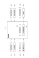
図5に示すように、本実施形態の苗取量調節システムに、制御装置Cと、枚数取得部31と、長さ取得部32と、縦送り検出部33と、横送り検出部34と、が備えられている。制御装置Cは、例えば田植機に備えられたECU(エレクトロニック・コントロール・ユニット)等のマイコン機器などに組み込まれたプログラムやハードウェアの集合体として構成されている。制御装置Cに、苗取量調節部30と作業情報取得部35とが備えられている。
図5に示すように、本実施形態の苗取量調節システムに、制御装置Cと、枚数取得部31と、長さ取得部32と、縦送り検出部33と、横送り検出部34と、が備えられている。制御装置Cは、例えば田植機に備えられたECU(エレクトロニック・コントロール・ユニット)等のマイコン機器などに組み込まれたプログラムやハードウェアの集合体として構成されている。制御装置Cに、苗取量調節部30と作業情報取得部35とが備えられている。
苗取量調節部30は、第一苗切れセンサ23と、枚数取得部31と、長さ取得部32と、縦送り検出部33と、横送り検出部34と、の夫々から情報を受信し、当該情報に基づいて苗取量を設定したり変更したりするために苗取量変更機構25を制御するように構成されている。
作業情報取得部35は、横送り検出部34によって検出された横送り量を作業情報として取得する。また、作業情報取得部35は、横送り量以外にも、縦送り検出部33によって検出された縦送り回数(縦送り量)、第一苗切れセンサ23の検出結果、及び、第二苗切れセンサ24の検出結果、等を作業情報として取得する。これらの作業情報は作業情報取得部35から報知部26へ送られる。
報知部26は、例えば運転部4の操作パネルに備えられる表示モニタであっても良いし、積層表示灯であっても良いし、ブザーや音声スピーカ等であっても良いし、オペレータ等が携帯所持する携帯端末(スマートフォンやタブレットコンピュータ)等であっても良い。報知部26は、横送り量を含む作業情報を報知するように構成されている。また、報知部26は、苗取量調節部30が算出した実苗取量等の算出結果を受信し、実苗取量等を報知したり、当該算出結果に基づいて圃場において必要な苗マットの枚数等を報知したりする構成であっても良い。
枚数取得部31と長さ取得部32との夫々は、例えば運転部4の操作パネルで設定されるものであっても良いし、遠隔地の管理コンピュータや携帯端末から無線通信ネットワークを介して受信するものであっても良い。携帯端末とは、例えばスマートフォンやタブレットコンピュータ等である。
枚数取得部31は、圃場において苗の植え付けに使用する使用予定の苗マットの枚数(予定使用枚数)を取得する。苗マットの予定使用枚数は、苗の種別、単位面積あたりの株数等に基づいて設定される。
長さ取得部32は、植付機構による作業開始前に苗載台14において、載置された苗マットが存在する領域の縦方向における実際の長さL3(図7参照)を取得するように構成されている。本実施形態では、苗載台14の上部に縦方向に沿って目盛り14B(図3及び図4参照)が刻まれている。作業者は、載置面区画14aに載置されている苗マットの上端の位置、即ち苗上端位置を目盛り14Bで読み取って長さ取得部32に目盛り14Bの情報を入力する。苗載台14において苗マットが存在する領域の縦方向における実際の長さL3は、『第二長さ』に相当する。
また、長さ取得部32は、苗載台14に載置される前の苗マットの縦方向の寸法L2(図7参照)も取得可能に構成されている。一枚の苗マットの縦方向の寸法L1(図7参照)は、予め規格(例えば580mm)で設定されている場合もある。長さ取得部32は、既知の寸法L2を取得する構成であっても良いし、人為入力に基づいて寸法L2を取得する構成であっても良い。
縦送り検出部33は、図2に示す縦送り機構21の受動アーム21d、駆動軸21f、及び、縦送りベルト21gが作動したことを検出するスイッチ式のセンサである。横送り検出部34は、リンク式操作具40(図8参照)に連動連結された揺動式のポテンショメータである。横送り検出部34は、リンク式操作具40の揺動レバー41の位置を検出することによって、横送り機構22の横送り量を検出する。横送り量とは、横送り機構22が往復駆動する速さである。横送り機構22が往復運動するストローク量を横送り量で割り算すると、横送り回数が算出される。換言すると、横送り検出部34は、縦送り機構21が一度駆動してから次に駆動するまでの間における横送り回数を検出する。
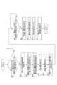
図6に示すフローチャートに基づいて、苗取量調節制御の流れについて説明する。ステップ#01において、苗取量調節部30は、田植え作業が開始される前に、苗載台14に苗マットが投入されたか否かを判定する。このときの苗マットの投入とは、少なくとも、第一苗切れセンサ23が配置された載置面区画14aに苗マットが全く載置されていない状態から、第一苗切れセンサ23が苗切れ状態を検出しない状態になるまで苗マットが投入されたことを意味する。苗取量調節部30は、第一苗切れセンサ23が苗切れ状態を検出していない状態であるか否かを判定する。第一苗切れセンサ23が苗切れ状態を検出していれば(ステップ#01:No)、ステップ#01の判定がループする。
第一苗切れセンサ23が苗切れ状態を検出していない状態であれば(ステップ#01:Yes)、ステップ#02~ステップ#06において、苗取量調節部30は、苗取量を初期設定するために必要な情報を取得する。
ステップ#02において、苗取量調節部30は、圃場において苗の植え付けに使用する使用予定の苗マットの枚数(予定使用枚数)を枚数取得部31から取得する。予定使用枚数は、圃場全体における予定使用枚数であっても良いし、単位面積(例えば10アール)当たりの予定使用枚数であっても良い。
ステップ#03において、苗取量調節部30は、苗載台14に載置される前の苗マットの縦方向の寸法L2を長さ取得部32から取得する。図7に、その寸法L2が示されている。寸法L2は、苗マット一枚分の寸法L1と、苗載台14に載置される苗マットの縦方向の枚数と、から導出される。本実施形態では、苗載台14は縦方向に二枚の苗マットを載置可能に構成されている。このため、寸法L2は『寸法L1×2』である。
ステップ#04において、苗取量調節部30は、苗載台14に載置された苗マットの縦方向の実際の長さL3を長さ取得部32から取得する。図7に、その長さL3が示されている。苗載台14の上部に縦方向に沿って目盛り14Bが刻まれているため、その目盛り14Bに基づいて長さL3が取得される。
ステップ#05において、苗取量調節部30は潰れ量ΔLを長さ取得部32から取得する。図7に示すように、長さ取得部32は、苗載台14に載置される前の苗マットの縦方向の寸法L2と、苗載台14に載置された苗マットの実際の長さL3と、の差分に基づいて苗マットが苗載台14に載置された際の潰れ量ΔLを取得する。つまり、潰れ量ΔLは『寸法L2-長さL3』である。
ステップ#06において、苗取量調節部30は、横送り検出部34によって検出された横送り機構22の横送り量(横送り回数)を取得する。横送り量の違いによって、設定するべき苗取量が異なるためである。
そしてステップ#07において苗取量調節部30は、ステップ#02~ステップ#06の処理で取得した情報に基づいて、植付アーム15における苗取量を初期設定として算出する。このとき、苗取量調節部30は、潰れ量ΔLに基づいて苗取量を精度良く初期設定する。
苗取量が初期設定されると、田植機の田植え作業が開始される。ステップ#08において苗取量調節部30は、第一苗切れセンサ23が苗切れ状態を検出したか否かを判定する。ステップ#07において苗取量が初期設定された直後であればステップ#08の判定はNoとなるが、田植機の田植え作業が継続されると、苗載台14に載置された苗の残量が減少し続ける。そして、第一苗切れセンサ23が配置されている載置面区画14aにおいて、苗上端位置が第一高さ位置H1以下になると、第一苗切れセンサ23は苗切れ状態を検出する(ステップ#08:Yes)。図7においては、苗上端位置が第一高さ位置H1以下になったときの苗マットの縦方向の長さL4を示している。
ステップ#08でYesの判定になったタイミングで、第一苗切れセンサ23が苗切れ状態を検出したときに苗載台14に残された苗マットの縦方向の長さ(第一長さ)は、図7に示す長さL4で既知である。このため、苗取量調節部30は、苗取量が初期設定されたときの苗マットの縦方向の実際の長さL3と、第一苗切れセンサ23が苗切れ状態を検出したときに苗載台14に残された苗マットの縦方向の長さL4と、の差分を算出する。この差分は、図7に示すように、消費分の長さL5である。ステップ#09において苗取量調節部30は、苗マットの縦方向における消費分の長さL5を算出する。
ステップ#10において苗取量調節部30は、ステップ#07において苗取量が初期設定されてからステップ#08において第一苗切れセンサ23が苗切れ状態を検出する(ステップ#08:Yes)までの間の縦送り機構21の縦送り回数を縦送り検出部33から取得する。
そして苗取量調節部30は、苗マットの縦方向における消費分の長さL5と、苗取量が初期設定されてから第一苗切れセンサ23が苗切れ状態を検出するまでの間の縦送り機構21の縦送り回数と、に基づいて植付アーム15における実際の苗取量(実苗取量)を算出する(ステップ#11)。縦送り機構21における一回当たりの縦送り量は予め設定されているため、一回当たりの縦送り量に縦送り回数を掛け算することによって、苗マットの計算上の総縦送り量を算出できる。
縦送り機構21の縦送り回数が苗マットの縦方向における消費分の長さL5に対して少ない場合、苗マットの計算上の総縦送り量が長さL5よりも短くなる。苗マットの計算上の総縦送り量が長さL5よりも短い場合、苗マットが柔らかくて崩れ易い等の要因によって、植付アーム15が目標の苗取量よりも多くの苗を取り出している。
縦送り機構21の縦送り回数が苗マットの縦方向における消費分の長さL5に対して多い場合、苗マットの計算上の総縦送り量が長さL5よりも長くなる。苗マットの計算上の総縦送り量が長さL5よりも長い場合、苗マットが硬い等の要因によって、植付アーム15が目標の苗取量よりも少なめの苗を取り出している。
実苗取量が算出されると、苗取量調節部30は、植付アーム15の実際の苗取量が目標の苗取量に近づくように苗取量変更機構25を制御する(ステップ#12)。植付アーム15は苗載台14の下端部から苗を取り出すため、植付アーム15の実際の苗取量は、植付アーム15が苗を取り出す際の植付アーム15と苗載台14の下端部との距離が関係する。このため、実苗取量が目標の苗取量よりも少ない場合、苗取量調節部30は、植付アーム15が苗を取り出す際の植付アーム15と苗載台14の下端部との距離が短くなるように、苗取量変更機構25を制御する。また、実苗取量が目標の苗取量よりも多い場合、苗取量調節部30は、植付アーム15が苗を取り出す際の植付アーム15と苗載台14の下端部との距離が長くなるように、苗取量変更機構25を制御する。
このように、苗取量調節部30は、第一苗切れセンサ23が苗切れ状態を検知したことに応じて、縦送り検出部33の検出結果に基づいて苗マットから苗を取り出す植付アーム15の苗取量を調節する。この構成によって、苗マットを予め用意した枚数を圃場に精度良く植え切ることが可能となり、苗マットが不足したり苗マットが余ったりする可能性が軽減される。
〔横送り機構の横送り量を変更するリンク式操作具〕
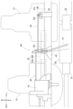
図8に示すように、本実施形態の田植機では、横送り機構22の横送り量を変更するリンク式操作具40が備えられている。リンク式操作具40に、揺動レバー41と、第一ロッド42と、ブラケット43と、第二ロッド44と、が備えられている。
図8に示すように、本実施形態の田植機では、横送り機構22の横送り量を変更するリンク式操作具40が備えられている。リンク式操作具40に、揺動レバー41と、第一ロッド42と、ブラケット43と、第二ロッド44と、が備えられている。
苗載台14の底部に支持フレーム14Fが備えられ、支持フレーム14Fは機体左右方向に沿って延びる。支持フレーム14Fにブラケット43がボルトで固定され、揺動レバー41はブラケット43にピンで揺動軸芯P2まわりに揺動可能に支持されている。つまり、揺動レバー41はブラケット43を介して支持フレーム14Fに支持されている。
揺動レバー41のうち、揺動軸芯P2よりも前側の部分は作業者の人為操作を受け付ける操作部分である。また、揺動レバー41のうち、揺動軸芯P2よりも後側の端部に第一ロッド42が枢支連結されている。
作業者が揺動レバー41を揺動操作すると、第一ロッド42が左右に変位する。第一ロッド42のうち、揺動レバー41と枢支連結されている側と反対側の端部は、伝動機構16の内部の機構と連結されている。伝動機構16の内部に横送り量変更機構が内蔵されている。横送り量変更機構は横送り量を変更する。横送り量は、横送り機構22が往復駆動する速さである。第一ロッド42が左右に変位することによって、伝動機構16の内部の横送り量変更機構が連動して動作し、横送り機構22の横送り量が変更される。リンク式操作具40は、横送り量変更機構と連結され、横送り機構22の横送り量を変更するための人為操作を受け付ける。
横送り検出部34が揺動レバー41の位置を検出する構造について説明する。横送り検出部34は、リンク式操作具40の操作に基づいて変更される横送り量を検出する。横送り検出部34は、第二ロッド44を介して揺動レバー41と連結されている。第二ロッド44の一端部は、揺動レバー41のうちの揺動軸芯P2の位置する部分と第一ロッド42との連結部分との間の箇所に枢支連結されている。つまり、第二ロッド44は、揺動レバー41のうち、第一ロッド42との連結箇所よりも揺動レバー41の揺動軸芯P2側の箇所に枢支連結されている。第二ロッド44の他端部は、横送り検出部34におけるポテンショメータの入力軸に連結された揺動アームの遊端部に枢支連結されている。これにより、揺動レバー41が揺動操作されると、横送り検出部34のポテンショメータが連動して回動する。このことから、横送り検出部34は、横送り量変更機構の動きに連動して横送り量を自動的に検出する。
横送り検出部34におけるポテンショメータの回動軸芯P3と第二ロッド44の連結箇所との距離D2は、揺動レバー41における揺動軸芯P2と第二ロッド44の連結箇所との距離D1よりも短い。このため、揺動レバー41が揺動操作されると、横送り検出部34のポテンショメータが揺動レバー41の揺動よりも大きな角度で回動する。これにより、揺動レバー41の操作量が横送り検出部34で増幅される。このことから、揺動レバー41の操作量が僅かであっても、横送り検出部34は揺動レバー41の位置をしっかりと検出できる。
横送り検出部34は、リンク式操作具40を挟んで伝動機構16側と反対側に配置されている。具体的には、伝動機構16は機体の左右方向における中央領域に配置され、横送り検出部34は、伝動機構16に対して機体横外側の領域に配置されている。横送り機構22は機体の左右方向に沿って延ばされている。横送り検出部34は、機体の左右方向において横送り機構22の機体横外側の端部よりも機体横外側の領域に配置されている。
機体左右方向において揺動レバー41と伝動機構16との間に横送り機構22が存在する。また、揺動レバー41の前方に整地ロータ50があり、機体左右方向において揺動レバー41と伝動機構16との間に整地ロータ50を昇降駆動するための昇降駆動機構51がある。このため、揺動レバー41と伝動機構16との間に横送り検出部34を配置すると、狭いスペースに横送り検出部34を配置する必用があり、作業者が横送り検出部34を組付ける際の作業が煩雑になる。図8に示すように、横送り検出部34がリンク式操作具40を挟んで伝動機構16側と反対側に配置される構成であれば、揺動レバー41と伝動機構16との間のスペースよりも広いスペースに横送り検出部34を組付けることが可能となる。
整地ロータ50のフレームに泥除け板52が取り付けられている。図8に示していないが、泥除け板52の前方に車輪2が存在する。泥除け板52は、車輪2が跳ね上げた泥を後方で受け止める。そして、横送り検出部34は泥除け板52の後方に配置されている。横送り検出部34は、機体前後方向視において泥除け板52と重複する。これにより、横送り検出部34は、車輪2が跳ね上げた泥を浴び難くなる。また、横送り検出部34は整地フロート13の真上に設けられている。これにより、横送り検出部34は下方からの泥を浴び難くなる。
〔別実施形態〕
本発明は、上述の実施形態に例示された構成に限定されるものではなく、以下、本発明の代表的な別実施形態を例示する。
本発明は、上述の実施形態に例示された構成に限定されるものではなく、以下、本発明の代表的な別実施形態を例示する。
(1)上述の実施形態では、横送り検出部34は、機体の左右方向において横送り機構22の機体横外側の端部よりも機体横外側の領域に配置されている。この実施形態に限定されず、例えば横送り検出部34は、機体の左右方向において横送り機構22の機体横外側の端部に対応する領域に配置されても良い。
(2)上述の実施形態では、リンク式操作具40は揺動レバー41を備え、揺動レバー41は揺動軸芯P2まわりに揺動する。この実施形態に限定されず、例えば揺動レバー41はスライド式のレバーであっても良い。
(3)上述の実施形態では、揺動レバー41と横送り検出部34との夫々が同一の支持フレーム14Fに支持されている。この実施形態に限定されず、例えば揺動レバー41が支持フレーム14Fに支持され、横送り検出部34は支持フレーム14Fとは別体のフレームに支持される構成であっても良い。
(4)上述の実施形態では、横送り検出部34はポテンショメータである。この実施形態に限定されず、例えば横送り検出部34は、磁気式や光学式等のリニアゲージセンサで揺動レバー41の位置を検出するものであっても良いし、LiDAR等のような測距装置で揺動レバー41の位置を検出するものであっても良い。また、所定の横送り位置を接触式センサで検出するものであってもよい。
(5)上述の実施形態では、移植機の一例として乗用型田植機を例示した。この実施形態に限定されず、例えば移植機は、野菜移植機であっても良いし、ポット苗移植機であっても良いし、歩行型田植機であっても良い。
なお、上述の実施形態(別実施形態を含む、以下同じ)で開示される構成は、矛盾が生じない限り、他の実施形態で開示される構成と組み合わせて適用することが可能である。また、本明細書において開示された実施形態は例示であって、本発明の実施形態はこれに限定されず、本発明の目的を逸脱しない範囲内で適宜改変することが可能である。
本発明は、移植機に適用可能である。
1 :機体
14 :苗載台
15 :植付アーム(植付機構)
16 :伝動機構(横送り量変更機構)
22 :横送り機構
26 :報知部
34 :横送り検出部(検出部)
35 :作業情報取得部(取得部)
40 :リンク式操作具
41 :揺動レバー
42 :第一ロッド
44 :第二ロッド
P2 :揺動レバーの揺動軸芯
14 :苗載台
15 :植付アーム(植付機構)
16 :伝動機構(横送り量変更機構)
22 :横送り機構
26 :報知部
34 :横送り検出部(検出部)
35 :作業情報取得部(取得部)
40 :リンク式操作具
41 :揺動レバー
42 :第一ロッド
44 :第二ロッド
P2 :揺動レバーの揺動軸芯
Claims (9)
- 苗マットを載置する苗載台と、
前記苗マットから苗を取り出して圃場に苗を移植する植付機構と、
前記植付機構の駆動と連動して前記苗載台を左右方向に往復駆動する横送り機構と、
前記横送り機構が往復駆動する速さである横送り量を変更する横送り量変更機構と、
前記横送り量変更機構の動きに連動して前記横送り量を自動的に検出する検出部と、が備えられている移植機。 - 前記横送り量変更機構と連結され、前記横送り量を変更するための人為操作を受け付けるリンク式操作具が備えられ、
前記検出部は、前記リンク式操作具の操作に基づいて変更される前記横送り量を検出するように構成され、
前記検出部は、前記リンク式操作具を挟んで前記横送り量変更機構側と反対側に配置されている請求項1に記載の移植機。 - 前記横送り量変更機構は機体の左右方向における中央領域に配置され、
前記検出部は、前記横送り量変更機構に対して機体横外側の領域に配置されている請求項1または2に記載の移植機。 - 前記横送り機構は機体の左右方向に沿って延ばされ、
前記検出部は、機体の左右方向において前記横送り機構の機体横外側の端部に対応する領域に配置されている請求項1から3の何れか一項に記載の移植機。 - 前記横送り機構は機体の左右方向に沿って延ばされ、
前記検出部は、機体の左右方向において前記横送り機構の機体横外側の端部よりも機体横外側の領域に配置されている請求項1から3の何れか一項に記載の移植機。 - 前記横送り量変更機構と連結され、前記横送り量を変更するための人為操作を受け付けるリンク式操作具が備えられ、
前記リンク式操作具に、前記人為操作を受け付ける揺動レバーと、前記揺動レバーに枢支連結されるとともに前記横送り量変更機構に連結された第一ロッドと、前記揺動レバーに枢支連結されるとともに前記検出部に連結された第二ロッドと、が備えられている請求項1から5の何れか一項に記載の移植機。 - 前記第二ロッドは、前記揺動レバーのうち、前記第一ロッドとの連結箇所よりも前記揺動レバーの揺動軸芯側の箇所に枢支連結されている請求項6に記載の移植機。
- 前記検出部は、揺動式のポテンショメータであって、前記第二ロッドに枢支連結されている請求項6または7に記載の移植機。
- 前記検出部によって検出された前記横送り量を作業情報として取得する取得部と、
前記横送り量を含む前記作業情報を報知する報知部と、が備えられている請求項1から8の何れか一項に記載の移植機。
Applications Claiming Priority (2)
| Application Number | Priority Date | Filing Date | Title |
|---|---|---|---|
| JP2023-217803 | 2023-12-25 | ||
| JP2023217803A JP2025101160A (ja) | 2023-12-25 | 2023-12-25 | 移植機 |
Publications (1)
| Publication Number | Publication Date |
|---|---|
| WO2025142201A1 true WO2025142201A1 (ja) | 2025-07-03 |
Family
ID=96217379
Family Applications (1)
| Application Number | Title | Priority Date | Filing Date |
|---|---|---|---|
| PCT/JP2024/040958 Pending WO2025142201A1 (ja) | 2023-12-25 | 2024-11-19 | 移植機 |
Country Status (2)
| Country | Link |
|---|---|
| JP (1) | JP2025101160A (ja) |
| WO (1) | WO2025142201A1 (ja) |
Citations (3)
| Publication number | Priority date | Publication date | Assignee | Title |
|---|---|---|---|---|
| JP2009100716A (ja) * | 2007-10-25 | 2009-05-14 | Kubota Corp | 苗植付け装置 |
| JP2019176827A (ja) * | 2018-03-30 | 2019-10-17 | 株式会社クボタ | 苗植付け装置 |
| JP2023015792A (ja) * | 2021-07-20 | 2023-02-01 | ヤンマーホールディングス株式会社 | 圃場作業機 |
-
2023
- 2023-12-25 JP JP2023217803A patent/JP2025101160A/ja active Pending
-
2024
- 2024-11-19 WO PCT/JP2024/040958 patent/WO2025142201A1/ja active Pending
Patent Citations (3)
| Publication number | Priority date | Publication date | Assignee | Title |
|---|---|---|---|---|
| JP2009100716A (ja) * | 2007-10-25 | 2009-05-14 | Kubota Corp | 苗植付け装置 |
| JP2019176827A (ja) * | 2018-03-30 | 2019-10-17 | 株式会社クボタ | 苗植付け装置 |
| JP2023015792A (ja) * | 2021-07-20 | 2023-02-01 | ヤンマーホールディングス株式会社 | 圃場作業機 |
Also Published As
| Publication number | Publication date |
|---|---|
| JP2025101160A (ja) | 2025-07-07 |
Similar Documents
| Publication | Publication Date | Title |
|---|---|---|
| JP7591599B2 (ja) | 苗移植機 | |
| JP7210662B2 (ja) | 苗移植機 | |
| JP6638698B2 (ja) | 作業車両 | |
| CN107072150B (zh) | 联合收割机 | |
| TWI625093B (zh) | 施肥裝置 | |
| JP7621215B2 (ja) | 圃場作業機 | |
| JP2025101160A (ja) | 移植機 | |
| JP2025101159A (ja) | 苗使用量管理システム | |
| KR101859776B1 (ko) | 포장용 공급 작업차의 통지 제어 구조 | |
| JP2025101158A (ja) | 移植機 | |
| JP7598562B2 (ja) | 作業車両 | |
| JP7724760B2 (ja) | 田植機 | |
| CN110301199A (zh) | 乘用型插秧机及秧苗栽植装置 | |
| CN122070046A (en) | Transplanting machine | |
| JP2003180152A (ja) | 精密農法 | |
| JP2023015791A (ja) | 圃場作業機 | |
| US20260114374A1 (en) | Work method, work program, and work system | |
| JP7859554B2 (ja) | 作業車両 | |
| JP7713173B2 (ja) | 移植機 | |
| JP7808282B1 (ja) | コンバイン | |
| JP7711691B2 (ja) | 苗移植機 | |
| JP7601035B2 (ja) | 農作業機 | |
| JP7047874B2 (ja) | 作業車両 | |
| JP2008271841A (ja) | 根菜収穫機 | |
| JP2025079252A (ja) | 苗移植機 |
Legal Events
| Date | Code | Title | Description |
|---|---|---|---|
| 121 | Ep: the epo has been informed by wipo that ep was designated in this application |
Ref document number: 24912094 Country of ref document: EP Kind code of ref document: A1 |