WO2025141872A1 - 交流直流変換装置、回転機駆動装置及び冷凍サイクル適用機器 - Google Patents
交流直流変換装置、回転機駆動装置及び冷凍サイクル適用機器 Download PDFInfo
- Publication number
- WO2025141872A1 WO2025141872A1 PCT/JP2023/047283 JP2023047283W WO2025141872A1 WO 2025141872 A1 WO2025141872 A1 WO 2025141872A1 JP 2023047283 W JP2023047283 W JP 2023047283W WO 2025141872 A1 WO2025141872 A1 WO 2025141872A1
- Authority
- WO
- WIPO (PCT)
- Prior art keywords
- current
- power supply
- switching element
- converter
- control unit
- Prior art date
- Legal status (The legal status is an assumption and is not a legal conclusion. Google has not performed a legal analysis and makes no representation as to the accuracy of the status listed.)
- Pending
Links
Images








Classifications
-
- H—ELECTRICITY
- H02—GENERATION; CONVERSION OR DISTRIBUTION OF ELECTRIC POWER
- H02M—APPARATUS FOR CONVERSION BETWEEN AC AND AC, BETWEEN AC AND DC, OR BETWEEN DC AND DC, AND FOR USE WITH MAINS OR SIMILAR POWER SUPPLY SYSTEMS; CONVERSION OF DC OR AC INPUT POWER INTO SURGE OUTPUT POWER; CONTROL OR REGULATION THEREOF
- H02M1/00—Details of apparatus for conversion
- H02M1/12—Arrangements for reducing harmonics from AC input or output
Definitions
- Patent Document 1 the conventional technology described in Patent Document 1 is a method of checking whether or not the harmonic standard can be complied with by repeated trials, so there is a problem that the number of trials increases exponentially as the number of pulses increases. In addition, there is a problem that it takes a long time to complete the design for the control gain design because there is no clear guideline for quantitative and unique design. To address this issue, there is a method of suppressing power supply harmonics by using a PS (Proportional Sinusoidal) controller in which an S (Sinusoidal) controller with high tracking performance for sine wave commands is connected in parallel to a P (Proportional) controller.
- PS Proportional Sinusoidal
- the AC-DC conversion device includes a rectifier circuit having at least one switching element and rectifying a power supply voltage applied from a single-phase AC power supply, a capacitor connected to a DC bus and smoothing the output voltage of the rectifier circuit, a reactor arranged on the single-phase AC power supply side of the capacitor, a control unit generating a switching signal for controlling the switching element, and a current detection circuit using a shunt resistor connected in series with the switching element.
- the switching element is arranged on the single-phase AC power supply side of the capacitor.
- the AC-DC converter disclosed herein has the advantage of being able to comply with harmonic standards without relying on trial-and-error adjustments, while suppressing increases in circuit costs and decreases in current detection accuracy.
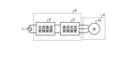
- FIG. 1 is a block diagram showing a configuration example of a rotary machine driving device according to a first embodiment; A circuit diagram showing a configuration example of an AC-DC converter according to a first embodiment.
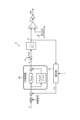
- FIG. 2 is a diagram showing a configuration example of a control unit included in the AC-DC converter according to the first embodiment;
- FIG. 1 is a diagram showing examples of operational waveforms of a power supply voltage, a bus voltage, and a power supply current when a control unit of an AC-DC converter according to a first embodiment includes a PS controller.
- FIG. 1 is a diagram showing an example of current harmonic characteristics when a control unit of an AC-DC converter according to a first embodiment includes a PS controller;
- ACR is an abbreviation of Automatic Current Regulator.
- KpACR is a proportional gain
- KsACR is an S control gain
- ⁇ n is an angular frequency
- s is a Laplace operator.
- the PS control is a control in which the S control, which is a Laplace transform expression of a cos function, is introduced in addition to the proportional control (P control). As shown in FIG. 3, the PS controller 60 is configured such that the lower S controller is connected in parallel to the upper P controller.
- the control unit 6 also includes a PS controller 60 as a current controller, but the configuration of the PS controller 60 is not limited to the example in FIG. 3.
- the control unit 6 may include a PS controller 60 including multiple S controllers.
- the control unit 6 includes a PS controller 60 that is a current controller that controls the power supply current of the AC power supply 1, and the PS controller 60 that is a current controller includes at least one controller that satisfies the internal model principle for sine waves.
- FIG. 4 is a diagram showing an example of the operating waveforms of the power supply voltage, the bus voltage Vdc , and the power supply current when the control unit 6 of the AC-DC converter 2 according to the first embodiment includes the PS controller 60.
- the upper part of FIG. 4 shows the waveforms of the bus voltage Vdc and the absolute value of the power supply voltage
- the lower part of FIG. 4 shows the waveforms of the detected power supply current, the fundamental component of the detected power supply current, and the power supply current command value.
- the fundamental component of the detected power supply current is almost equal to the power supply current command value.
- FIG. 5 is a diagram showing an example of current harmonic characteristics when the control unit 6 of the AC-DC converter 2 according to the first embodiment includes a PS controller 60.
- the current harmonic standard used in FIG. 5 is IEC (International Electrotechnical Commission) 61000-3-2 Class A. Note that IEC 61000-3-2 Class A is an example of a current harmonic standard, and is not limited to this standard.
- the second to fortieth current harmonic standard values shown in IEC 61000-3-2 Class A are shown by solid lines. Also, in FIG. 5, the effective values of the second to fortieth harmonic components during rated operation are shown by dashed lines.
- the harmonic components during rated operation represent the remaining components obtained by excluding the fundamental wave component of the power supply current from the power supply current that flows when the AC-DC converter 2 is operated at rated power.
- the second to fortieth harmonics are defined as "low-order harmonics".
- the waveforms of the dashed lines are lower than the waveforms of the solid lines from the 2nd to the 40th orders. This shows that if a PS controller 60 with high tracking performance for sine wave input is applied to the control unit 6, the low-order harmonics contained in the power supply current will comply with the harmonic standard value of the power supply current.
- FIG. 5 shows the harmonic components during rated operation as an example, but it goes without saying that the effect of suppressing harmonic components by the PS controller 60 can be obtained even when not operating at rated speed.
- the control unit 6 performs control to suppress harmonic components by treating the current flowing through the switching element 215 detected by the current detection unit 210 as the current flowing through the reactor 212, i.e., the power supply current.
- the current detection unit 210 detects the current flowing through the switching element 215 when the switching element 215 is on. In other words, the current detection unit 210 cannot detect the current flowing through the switching element 215 when the switching element 215 is off.
- the control unit 6 cannot obtain current information from the current detection unit 210 when the switching element 215 is off. Therefore, in this embodiment, the control unit 6 performs control to suppress harmonic components by estimating the power supply current during the period when the current detection unit 210 cannot detect the current, i.e., by complementing the detected current.
- the control unit 6 of the AC-DC converter 2 estimates the power supply current isFB and complements the detected current during a period when the switching element 215 is off and the current detection unit 210 cannot detect the shunt current as the power supply current is .
- This allows the control unit 6 to comply with harmonic standards without relying on trial and error adjustments, while suppressing an increase in circuit costs and a decrease in current detection accuracy.
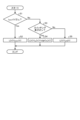
- FIG. 9 is a flowchart showing the control contents of the control unit 6 of the AC-DC converter 2 according to the second embodiment.
- (n) and (n-1) indicate sampling timings.
- the sampling timing of (n-1) is the sampling timing one before the sampling timing of (n).
- i ACCT (n) indicates the current value detected by the current detection unit 211 which is the ACCT at the sampling timing of (n).
- i th is a defined threshold value indicating the current value at which the detection accuracy of the current detection unit 211 which is the ACCT deteriorates.
- the current value i ACCT (n) is equal to or greater than the threshold i th , good detection accuracy is obtained in the current detection unit 211.
- the minimum detectable current value defined by the manufacturer of the current detection unit 211 which is the ACCT may be used, or the detection accuracy of the current detection unit 211 which is the ACCT may be measured and the current value which can guarantee the accuracy may be set as the threshold, and the setting method is not particularly limited.
- i s (n) indicates the final detection value of the power supply current i s at the sampling timing of (n).
- i sh (n) indicates the current value detected by the current detection unit 210 using a shunt resistor at the sampling timing of (n).
- sign is a sign function, which returns a sign according to the polarity of the argument power supply voltage v s (n) at the sampling timing of (n). Note that, instead of the power supply voltage v s (n), the argument of the sign function sign may be a current command value, a phase locked by a PLL (Phase Locked Loop), or a current value at the previous sampling timing.
- i sFB (n) is the power supply current estimated by the estimation unit 61 at the sampling timing of (n).
- the control unit 6 judges whether the current value iACCT (n) detected by the current detection unit 211 is equal to or greater than the threshold value ith (step S1). If the current value iACCT (n) detected by the current detection unit 211 is equal to or greater than the threshold value ith (step S1: Yes), the current detection unit 210 can obtain good detection accuracy, so the control unit 6 adopts the current value iACCT (n) detected by the current detection unit 211 as the power supply current iS (n) at the sampling timing of (n) (step S2).
- step S3 If the current value iACCT (n) detected by the current detection unit 211 is less than the threshold value ith (step S1: No), the current detection unit 210 cannot obtain good detection accuracy, so the control unit 6 next judges whether the switching element 215 is on or off (step S3).
- step S3 When the switching element 215 is on (step S3: Yes), a current flows through the current detection unit 210 using a shunt resistor, so the control unit 6 adopts the current value i sh (n) detected by the current detection unit 210 multiplied by the sign function sign(v s (n)) as the power supply current i s (n) at the sampling timing (n) (step S4). Since the current value i sh (n) detected by the current detection unit 210 using a shunt resistor has only positive polarity, the control unit 6 compensates for the sign according to the polarity of the power supply voltage v s (n).
- step S3 When the switching element 215 is off (step S3: No), no current flows through the current detection unit 210 using a shunt resistor, so the control unit 6 adopts the power supply current i sFB (n) estimated by the estimation unit 61 as the power supply current i s (n) at the sampling timing (n) (step S5).
- the control unit 6 when the current value iACCT (n) detected by the current detection unit 211, which is an AC current transformer, is equal to or greater than the specified threshold value ith , the control unit 6 generates a switching signal using the current value iACCT (n) detected by the current detection unit 211, and when the current value iACCT (n) detected by the current detection unit 211 is less than the threshold value ith , the control unit 6 generates a switching signal using the current value iSH (n) flowing through the shunt resistor detected by the current detection unit 210 or the power supply current iSFB (n) estimated by the estimation unit 61.
- control unit 6 may adopt the power supply current i s (n-1) at the sampling timing (n-1), which is the previous sampling timing, as the power supply current i s (n) at the sampling timing (n) rather than the power supply current i sFB (n) estimated by the estimation unit 61.
- FIG. 10 is a diagram showing an example of an operation waveform when the control unit 6 of the AC-DC converter 2 according to the second embodiment adopts the power supply current i s (n-1) at the previous sampling timing when the switching element 215 is off.
- the control unit 6 adopts the power supply current i s (n-1) at the previous sampling timing, and as a result, there is a slight error between the true current value and the detected current.
- the section where the waveform of the true current value is horizontal near 0 A is also an area where the detection accuracy of the current detection unit 211, which is the ACCT, deteriorates. Therefore, although there is a possibility that a slight error occurs, the control unit 6 can suppress the deterioration of the current detection accuracy by adopting the power supply current i s (n-1) at the previous sampling timing.
- the control unit 6 of the AC-DC conversion device 2 estimates the power supply current isFB to complement the detected current during a period when the switching element 215 is off and the current detection unit 210 cannot detect the shunt current as the power supply current is, and also uses the current value iACCT (n) detected by the current detection unit 211 which is an ACCT arranged in the front or rear stage of the reactor 212. Even in this case, the control unit 6 can comply with harmonic standards without relying on trial and error adjustments, while suppressing an increase in circuit costs and a decrease in current detection accuracy.
- Embodiment 3 In the third embodiment, a different example of the AC-DC converter 2 including the control unit 6 described in the first and second embodiments will be described. Components having the same or equivalent functions as those of the AC-DC converter 2 described in the first and second embodiments will be denoted by the same reference numerals, and a description of the overlapping contents will be omitted.
- FIG. 11 is a diagram showing an example of the configuration of an AC-DC converter 2 according to a third embodiment.
- the rectifier circuit 20 has a configuration called a full PAM circuit.
- the rectifier circuit 20 includes a single-phase diode bridge cell 213a, a switching element 215, and a diode 218.
- the switching element 215 performs a switching operation at least once per half cycle of the power supply voltage.
- PIR Proportional Integral Resonant
- the positions and connection forms of the switching element 215 and the reactor 212 are different, but in all configurations, the switching element 215 and the reactor 212 are arranged closer to the AC power source 1 than the capacitor 216. This arrangement relationship is also the same in other embodiments described later. Also, in Figure 11, the current detection unit 210 is omitted, but the position of the current detection unit 210 does not matter as long as it is connected in series with the switching element 215. This arrangement relationship is also the same in other embodiments described later. Also, the same applies to cases in which multiple switching elements are provided in other embodiments.
- the switching element 215 is shown as an IGBT, but any element capable of switching operation may be used.
- the AC-DC converter 2 shown in FIG. 11 is configured as a closed loop, but it may be configured as an open loop. When the AC-DC converter 2 is configured as an open loop, the detection values of the voltage detectors 217a, 217b and the current detector 211 do not need to be used.
- the full PAM circuit of FIG. 11 may be used in the first and second embodiments, and the simple switching circuits of FIG. 2 and FIG. 8 may be used in the third embodiment.
- the rectifier circuit 20 has at least one switching element, but the control method described in this paper is applicable even if the control method for controlling the switching element is different.
- the transfer function of the PIR controller will be described.
- the transfer function G PIR(s) of the PIR controller can be expressed by the following equation (14).
- Kp is a proportional gain
- Ki is an integral gain
- Kr is a resonance control gain
- ⁇ 1 is the angular frequency of the current control response
- ⁇ 2 is the angular frequency of the sine wave command to be followed.
- a PIR controller having such a transfer function G PIR(s) may be applied to the control unit 6 of the first and second embodiments. The use of a PIR controller can also provide the same effects as the PS control.
- PIR control is applied to the control unit 6 in the third embodiment. Even when PIR control is applied instead of PS control, the same effects as those in the first and second embodiments can be obtained.
- Embodiment 4 a different example of the AC-DC converter 2 including the control unit 6 described in the first and second embodiments will be described. Components having the same or equivalent functions as those of the AC-DC converter 2 described in the first and second embodiments will be denoted by the same reference numerals, and a description of the overlapping contents will be omitted.
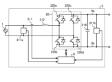
- FIG. 12 is a diagram showing an example of the configuration of an AC-DC converter 2 according to embodiment 4.
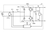
- the rectifier circuit 20 is composed of a single-phase H-bridge cell having four switching elements 220a, 220b, 220c, and 220d. Note that the configuration and operation of the rectifier circuit 20 shown in FIG. 12 are publicly known, and further explanation will be omitted here.
- the control unit 6 generates switching signals for the four switching elements 220a, 220b, 220c, and 220d using the control methods described in the first and second embodiments to drive them.
- the AC-DC converter 2 shown in FIG. 12 can achieve the same effects as those in the first and second embodiments.
- the switching elements 220a, 220b, 220c, and 220d are shown as IGBTs, but any elements capable of switching operation may be used.
- the AC-DC converter 2 shown in FIG. 12 is configured as a closed loop, but it may also be configured as an open loop. When the AC-DC converter 2 is configured as an open loop, the detection values of the voltage detectors 217a and 217b and the current detector 211 do not need to be used.
- Embodiment 5 a different example of the AC-DC converter 2 including the control unit 6 described in the first and second embodiments will be described. Components having the same or equivalent functions as those of the AC-DC converter 2 described in the first and second embodiments will be denoted by the same reference numerals, and a description of the overlapping contents will be omitted.
- FIG. 13 is a diagram showing an example of the configuration of an AC-DC converter 2 according to embodiment 5.
- the rectifier circuit 20 is composed of a single-phase H-bridge cell including two diodes 218a, 218b and two switching elements 220c, 220d.
- one leg is composed of a series circuit of diodes 218a, 218b, and the other leg is composed of a series circuit of switching elements 220c, 220d. Note that the configuration and operation of the rectifier circuit 20 shown in FIG. 13 are publicly known, and further description will be omitted here.
- the control unit 6 generates switching signals for the two switching elements 220c, 220d using the control methods described in the first and second embodiments to drive them. This allows the AC-DC converter 2 shown in FIG. 13 to achieve the same effects as those in the first and second embodiments.
- the switching elements 220c and 220d are shown as IGBTs, but any elements capable of switching operation may be used.
- the AC-DC converter 2 shown in FIG. 13 is configured as a closed loop, but it may also be configured as an open loop. When the AC-DC converter 2 is configured as an open loop, the detection values of the voltage detectors 217a and 217b and the current detector 211 do not need to be used.
- Embodiment 6 a different example of the AC-DC converter 2 including the control unit 6 described in the first and second embodiments will be described. Components having the same or equivalent functions as those of the AC-DC converter 2 described in the first and second embodiments will be denoted by the same reference numerals, and a description of the overlapping contents will be omitted.
- FIG. 14 is a diagram showing an example of the configuration of an AC-DC converter 2 according to embodiment 6.
- the rectifier circuit 20 is composed of a single-phase H-bridge cell including two diodes 218a, 218c and two switching elements 220b, 220d.
- the diodes 218a, 218c are arranged in the upper arms of the two legs, and the switching elements 220b, 220d are arranged in the lower arms of the two legs.
- the configuration and operation of the rectifier circuit 20 shown in FIG. 14 are publicly known, and further description will be omitted here.
- the control unit 6 generates switching signals for the two switching elements 220b and 220d using the control methods described in the first and second embodiments to drive them. This allows the AC-DC converter 2 shown in FIG. 14 to achieve the same effects as those in the first and second embodiments.
- the switching elements 220b and 220d are shown as IGBTs, but any elements capable of switching operation may be used.
- the AC-DC converter 2 shown in FIG. 14 is configured as a closed loop, but it may also be configured as an open loop. When the AC-DC converter 2 is configured as an open loop, the detection values of the voltage detectors 217a and 217b and the current detector 211 do not need to be used.
- Embodiment 7 In the seventh embodiment, a different example of the AC-DC converter 2 including the control unit 6 described in the first and second embodiments will be described. Components having the same or equivalent functions as those of the AC-DC converter 2 described in the first and second embodiments will be denoted by the same reference numerals, and a description of the overlapping contents will be omitted.
- FIG. 15 is a diagram showing an example of the configuration of an AC-DC converter 2 according to embodiment 7.
- the rectifier circuit 20 is composed of a single-phase H-bridge cell including two diodes 218a, 218b, four switching elements 220a, 220b, 220c, 220d, a capacitor 216b, and a voltage detector 217c.
- the voltage detector 217c may be provided outside the rectifier circuit 20.
- the capacitor 216 is shown as capacitor 216a.
- one leg is composed of a series circuit of diodes 218a and 218b, and the other leg is composed of a series circuit of switching elements 220a, 220b, 220c, and 220d.
- the capacitor 216b is connected between the connection point of the switching elements 220a and 220b and the connection point of the switching elements 220c and 220d.
- the voltage detection unit 217c detects the voltage of the capacitor 216b and outputs the detection value to the control unit 6.
- the control unit 6 generates a switching signal for controlling the switching elements 220a, 220b, 220c, and 220d based on the detection values of the voltage detection units 217a, 217b, and 217c and the current detection unit 211.
- the configuration and operation of the rectifier circuit 20 shown in FIG. 15 are publicly known, and further description will be omitted here.
- the switching elements 220a, 220b, 220c, and 220d are shown as IGBTs, but any elements capable of switching operation may be used.
- the AC-DC converter 2 shown in FIG. 15 is configured as a closed loop, but it may also be configured as an open loop. When the AC-DC converter 2 is configured as an open loop, the detection values of the voltage detectors 217a, 217b, and 217c and the current detector 211 do not need to be used.
- Embodiment 8 In the eighth embodiment, a different example of the AC-DC converter 2 including the control unit 6 described in the first and second embodiments will be described. Components having the same or equivalent functions as those of the AC-DC converter 2 described in the first and second embodiments will be denoted by the same reference numerals, and a description of the overlapping contents will be omitted.
- FIG. 16 is a diagram showing an example of the configuration of an AC-DC converter 2 according to embodiment 8.
- the rectifier circuit 20 is composed of a single-phase H-bridge cell 221 and a switching cell 222.
- the single-phase H-bridge cell 221 includes two diodes 218a and 218c and two switching elements 220b and 220d.
- the switching cell 222 includes four switching elements 220e, 220f, 220g, and 220h, a capacitor 216c, and a voltage detection unit 217c.
- the voltage detection unit 217c may be provided outside the switching cell 222.
- diodes 218a and 218c are arranged in the upper arms of the two legs, and switching elements 220b and 220d are arranged in the lower arms of the two legs.
- switching cell 222 shown in FIG. 16 four switching elements 220e, 220f, 220g, and 220h are bridge-connected.
- the capacitor 216c is connected in parallel to the first leg consisting of the switching elements 220e and 220f and the second leg consisting of the switching elements 220g and 220h.
- the voltage detection unit 217c detects the voltage of the capacitor 216c and outputs the detection value to the control unit 6.
- the control unit 6 generates switching signals for controlling the switching elements 220b, 220d, 220e, 220f, 220g, and 220h based on the detection values of the voltage detection units 217a, 217b, and 217c and the current detection unit 211. Note that the configuration and operation of the rectifier circuit 20 shown in FIG. 16 are publicly known, and further explanation will be omitted here.
- the control unit 6 generates switching signals for the six switching elements 220b, 220d, 220e, 220f, 220g, and 220h using the control methods described in the first and second embodiments. This allows the AC-DC converter 2 shown in FIG. 16 to achieve the same effects as those in the first and second embodiments.
- switching elements 220b, 220d, 220e, 220f, 220g, and 220h are shown as IGBTs, but any elements capable of switching operation may be used.
- the AC-DC converter 2 shown in FIG. 16 is configured as a closed loop, it may also be configured as an open loop. When the AC-DC converter 2 is configured as an open loop, the detection values of voltage detectors 217a, 217b, and 217c and current detector 211 do not need to be used.
- the switching elements 220a and 220b are shown as IGBTs, but any elements capable of switching operation may be used.
- the AC-DC converter 2 shown in FIG. 17 is configured as a closed loop, but it may also be configured as an open loop. When the AC-DC converter 2 is configured as an open loop, the detection values of the voltage detectors 217a and 217b and the current detector 211 do not need to be used.
- Embodiment 10 In the tenth embodiment, a different example of the AC-DC converter 2 including the control unit 6 described in the first and second embodiments will be described. Note that components having the same or equivalent functions as those of the AC-DC converter 2 described in the first and second embodiments will be denoted by the same reference numerals, and a description of the overlapping contents will be omitted.
Landscapes
- Engineering & Computer Science (AREA)
- Power Engineering (AREA)
- Rectifiers (AREA)
Priority Applications (2)
| Application Number | Priority Date | Filing Date | Title |
|---|---|---|---|
| PCT/JP2023/047283 WO2025141872A1 (ja) | 2023-12-28 | 2023-12-28 | 交流直流変換装置、回転機駆動装置及び冷凍サイクル適用機器 |
| JP2025566168A JPWO2025141872A1 (https=) | 2023-12-28 | 2023-12-28 |
Applications Claiming Priority (1)
| Application Number | Priority Date | Filing Date | Title |
|---|---|---|---|
| PCT/JP2023/047283 WO2025141872A1 (ja) | 2023-12-28 | 2023-12-28 | 交流直流変換装置、回転機駆動装置及び冷凍サイクル適用機器 |
Publications (1)
| Publication Number | Publication Date |
|---|---|
| WO2025141872A1 true WO2025141872A1 (ja) | 2025-07-03 |
Family
ID=96217160
Family Applications (1)
| Application Number | Title | Priority Date | Filing Date |
|---|---|---|---|
| PCT/JP2023/047283 Pending WO2025141872A1 (ja) | 2023-12-28 | 2023-12-28 | 交流直流変換装置、回転機駆動装置及び冷凍サイクル適用機器 |
Country Status (2)
| Country | Link |
|---|---|
| JP (1) | JPWO2025141872A1 (https=) |
| WO (1) | WO2025141872A1 (https=) |
Citations (4)
| Publication number | Priority date | Publication date | Assignee | Title |
|---|---|---|---|---|
| JPH0538152A (ja) * | 1991-07-25 | 1993-02-12 | Matsushita Electric Works Ltd | インバータ装置 |
| JP2016010210A (ja) * | 2014-06-24 | 2016-01-18 | パナソニックIpマネジメント株式会社 | 直流電源装置およびインバータ駆動装置およびこれを用いた空気調和機 |
| WO2016051487A1 (ja) * | 2014-09-30 | 2016-04-07 | 三菱電機株式会社 | 電力変換装置 |
| WO2020070814A1 (ja) * | 2018-10-03 | 2020-04-09 | 三菱電機株式会社 | 電力変換器の制御装置及びフィードバック制御装置 |
-
2023
- 2023-12-28 WO PCT/JP2023/047283 patent/WO2025141872A1/ja active Pending
- 2023-12-28 JP JP2025566168A patent/JPWO2025141872A1/ja active Pending
Patent Citations (4)
| Publication number | Priority date | Publication date | Assignee | Title |
|---|---|---|---|---|
| JPH0538152A (ja) * | 1991-07-25 | 1993-02-12 | Matsushita Electric Works Ltd | インバータ装置 |
| JP2016010210A (ja) * | 2014-06-24 | 2016-01-18 | パナソニックIpマネジメント株式会社 | 直流電源装置およびインバータ駆動装置およびこれを用いた空気調和機 |
| WO2016051487A1 (ja) * | 2014-09-30 | 2016-04-07 | 三菱電機株式会社 | 電力変換装置 |
| WO2020070814A1 (ja) * | 2018-10-03 | 2020-04-09 | 三菱電機株式会社 | 電力変換器の制御装置及びフィードバック制御装置 |
Also Published As
| Publication number | Publication date |
|---|---|
| JPWO2025141872A1 (https=) | 2025-07-03 |
Similar Documents
| Publication | Publication Date | Title |
|---|---|---|
| EP2290793B1 (en) | Converter device, module for driving motor, refrigerating apparatus, harmonic reducing device | |
| JP5557660B2 (ja) | 電力変換装置及び、それを用いた機器 | |
| JP7459308B2 (ja) | 電力変換装置、モータ駆動装置及び冷凍サイクル適用機器 | |
| EP2465189A2 (en) | System and method for power factor correction frequency tracking and reference generation | |
| US7113414B2 (en) | Inverter control device for driving a motor and an air conditioner | |
| JP7507894B2 (ja) | 電力変換装置、モータ駆動装置及び冷凍サイクル適用機器 | |
| KR102014257B1 (ko) | 전력변환장치 및 이를 포함하는 공기조화기 | |
| Cimini et al. | Current sensorless solution for PFC boost converter operating both in DCM and CCM | |
| WO2025141872A1 (ja) | 交流直流変換装置、回転機駆動装置及び冷凍サイクル適用機器 | |
| EP3101798B1 (en) | Rectifier device and method for controlling same | |
| KR20210092540A (ko) | 전력 변환 장치 및 이를 이용하는 공기 조화기 | |
| JP2004343823A (ja) | 空気調和機 | |
| JP7625158B1 (ja) | 交流直流変換装置、回転機駆動装置及び冷凍サイクル適用機器 | |
| WO2025141871A1 (ja) | 交流直流変換装置、回転機駆動装置及び冷凍サイクル適用機器 | |
| EP3419158B1 (en) | Power conversion device and air conditioning device using same | |
| JP7603907B1 (ja) | 交流直流変換装置、回転機駆動装置及び冷凍サイクル適用機器 | |
| JP7603906B1 (ja) | 交流直流変換装置、回転機駆動装置及び冷凍サイクル適用機器 | |
| WO2025141870A1 (ja) | 交流直流変換装置、回転機駆動装置及び冷凍サイクル適用機器 | |
| US20240396465A1 (en) | Power conversion device, motor drive device, and refrigeration-cycle application apparatus | |
| WO2025141868A1 (ja) | 交流直流変換装置、回転機駆動装置及び冷凍サイクル適用機器 | |
| JP7774774B1 (ja) | 交流直流変換装置、回転機駆動装置、冷凍サイクル適用機器及び交流直流変換装置の制御方法 | |
| WO2025141869A1 (ja) | 交流直流変換装置、回転機駆動装置及び冷凍サイクル適用機器 | |
| WO2025141866A1 (ja) | 交流直流変換装置、回転機駆動装置及び冷凍サイクル適用機器 | |
| WO2025141867A1 (ja) | 交流直流変換装置、回転機駆動装置及び冷凍サイクル適用機器 | |
| WO2025004328A1 (ja) | 電力変換装置および冷凍サイクル適用機器 |
Legal Events
| Date | Code | Title | Description |
|---|---|---|---|
| 121 | Ep: the epo has been informed by wipo that ep was designated in this application |
Ref document number: 23963217 Country of ref document: EP Kind code of ref document: A1 |
|
| ENP | Entry into the national phase |
Ref document number: 2025566168 Country of ref document: JP Kind code of ref document: A |
|
| WWE | Wipo information: entry into national phase |
Ref document number: 2025566168 Country of ref document: JP |