WO2025134841A1 - 移動装置、露光装置、移動体の駆動方法、露光方法及びデバイス製造方法 - Google Patents
移動装置、露光装置、移動体の駆動方法、露光方法及びデバイス製造方法 Download PDFInfo
- Publication number
- WO2025134841A1 WO2025134841A1 PCT/JP2024/043468 JP2024043468W WO2025134841A1 WO 2025134841 A1 WO2025134841 A1 WO 2025134841A1 JP 2024043468 W JP2024043468 W JP 2024043468W WO 2025134841 A1 WO2025134841 A1 WO 2025134841A1
- Authority
- WO
- WIPO (PCT)
- Prior art keywords
- moving body
- moving
- measurement system
- head
- axis direction
- Prior art date
- Legal status (The legal status is an assumption and is not a legal conclusion. Google has not performed a legal analysis and makes no representation as to the accuracy of the status listed.)
- Pending
Links
Images






Classifications
-
- G—PHYSICS
- G01—MEASURING; TESTING
- G01B—MEASURING LENGTH, THICKNESS OR SIMILAR LINEAR DIMENSIONS; MEASURING ANGLES; MEASURING AREAS; MEASURING IRREGULARITIES OF SURFACES OR CONTOURS
- G01B11/00—Measuring arrangements characterised by the use of optical techniques
- G01B11/02—Measuring arrangements characterised by the use of optical techniques for measuring length, width or thickness
-
- G—PHYSICS
- G03—PHOTOGRAPHY; CINEMATOGRAPHY; ANALOGOUS TECHNIQUES USING WAVES OTHER THAN OPTICAL WAVES; ELECTROGRAPHY; HOLOGRAPHY
- G03F—PHOTOMECHANICAL PRODUCTION OF TEXTURED OR PATTERNED SURFACES, e.g. FOR PRINTING, FOR PROCESSING OF SEMICONDUCTOR DEVICES; MATERIALS THEREFOR; ORIGINALS THEREFOR; APPARATUS SPECIALLY ADAPTED THEREFOR
- G03F7/00—Photomechanical, e.g. photolithographic, production of textured or patterned surfaces, e.g. printing surfaces; Materials therefor, e.g. comprising photoresists; Apparatus specially adapted therefor
- G03F7/20—Exposure; Apparatus therefor
-
- H—ELECTRICITY
- H10—SEMICONDUCTOR DEVICES; ELECTRIC SOLID-STATE DEVICES NOT OTHERWISE PROVIDED FOR
- H10P—GENERIC PROCESSES OR APPARATUS FOR THE MANUFACTURE OR TREATMENT OF DEVICES COVERED BY CLASS H10
- H10P72/00—Handling or holding of wafers, substrates or devices during manufacture or treatment thereof
- H10P72/50—Handling or holding of wafers, substrates or devices during manufacture or treatment thereof for positioning, orientation or alignment
Definitions
- the present invention relates to a moving apparatus, an exposure apparatus, a method for driving a moving body, an exposure method, and a device manufacturing method.
- an exposure apparatus is used to transfer a predetermined pattern on a mask (photomask) or reticle (collectively referred to as "mask”) to a photosensitive glass plate or wafer (collectively referred to as "substrate”) by exposing the substrate to illumination light (energy beam) via a projection optical system.
- a mask photomask
- reticle photosensitive glass plate or wafer
- This type of exposure apparatus requires highly accurate control of the position of the substrate relative to the projection optical system, and so is known to use a linear encoder system as a position measurement system for the stage on which the substrate is placed (see, for example, Patent Document 1).
- the optical path length of the laser to the bar mirror becomes long, and the effects of so-called air fluctuations cannot be ignored.
- a moving device includes a first moving body extending in a first direction and moving in a second direction intersecting the first direction, a second moving body moving in the second direction, a first head provided on one of the first moving body and the second moving body, and a scale extending in the first direction and provided on the other of the first moving body and the second moving body so as to face the first head, and a first measurement system that measures the position of the second moving body in the first direction using the first head and a second measurement system that obtains information regarding the distance between the first moving body and the second moving body.
- a method for driving a moving body is a method for moving a first moving body that extends in a first direction and moves in a second direction intersecting the first direction, and a second moving body that moves in the second direction, and includes measuring the position of the second moving body in the first direction using a first head provided on one of the first moving body and the second moving body and a scale provided on the other of the first moving body and the second moving body so as to extend in the first direction and face the first head, obtaining information regarding the gap between the first moving body and the second moving body, and driving the first moving body and the second moving body based on the measurement result regarding the second moving body and the information regarding the gap.
- a method for driving a moving body is a method for moving a first moving body that extends in a first direction and moves in a second direction intersecting the first direction, and a second moving body that moves in the second direction, and includes measuring the position of the second moving body in the first direction using a first head provided on one of the first moving body and the second moving body and a scale provided on the other of the first moving body and the second moving body so as to extend in the first direction and face the first head, acquiring information regarding the positional relationship between the first moving body and the second moving body in the second direction, measuring the position of the first moving body in the second direction, and controlling the position of the second moving body in the first direction and the second direction based on the measured position of the second moving body in the first direction, the acquired information regarding the positional relationship between the first moving body and the second moving body, and the measured position of the first moving body in the second direction.
- an exposure method is an exposure method for exposing an object using an exposure apparatus including a first moving body extending in a first direction and moving in a second direction intersecting the first direction, a second moving body moving in the second direction, an object held by the second moving body, and an optical system for irradiating light to the object, the exposure method including: measuring the position of the second moving body in the first direction using a first head provided on one of the first moving body and the second moving body, and a scale provided on the other of the first moving body and the second moving body so as to extend in the first direction and face the first head; acquiring information regarding the distance between the first moving body and the second moving body; controlling the movement of the first moving body and the second moving body based on the measurement result regarding the second moving body and the information regarding the distance; and exposing the object to light from the optical system while moving the second moving body holding the object in the first direction.
- FIG. 1 is a diagram showing roughly the configuration of an exposure apparatus according to a first embodiment.
- 1 is an external perspective view showing roughly the configuration of an exposure apparatus according to a first embodiment.
- 1 is a diagram illustrating a schematic configuration of an illumination optical apparatus according to a first embodiment.
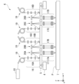
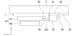
- FIG. 2 is a front view showing a schematic configuration of the stage moving device according to the first embodiment.
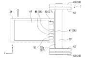
- FIG. 2 is a plan view illustrating a configuration of a stage moving device according to the first embodiment.
- 4 is a front view showing a schematic configuration of the stage movement device according to the first embodiment after movement;
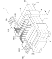
- FIG. 1 is an external perspective view showing a part of an exposure apparatus according to a first embodiment.
- 1 is an external perspective view of a part of an exposure apparatus according to a first embodiment, as viewed obliquely from above.
- FIG. 11 is a plan view illustrating a configuration of a stage moving device according to a second embodiment.
- FIG. 11 is a front view showing a schematic configuration of a stage moving device according to a second embodiment.
- FIG. 11 is a plan view showing a schematic configuration of a plurality of encoder measurement systems of a stage moving device according to a second embodiment.
- FIG. 13 is a plan view illustrating a configuration of a stage moving device according to a third embodiment.
- FIG. 13 is a front view illustrating a schematic configuration of a stage moving device according to a third embodiment.
- FIG. 13 is a plan view illustrating a configuration of a stage moving device according to a fourth embodiment.
- FIG. 11 is a plan view illustrating a configuration of a stage moving device according to a second embodiment.
- FIG. 11 is a front view showing a schematic configuration of a stage moving device according to a second embodiment.
- FIG. 11 is a plan view showing a schematic configuration of a plurality of
- FIG. 13 is a front view showing a schematic configuration of a stage moving device according to a fourth embodiment.
- FIG. 13 is a plan view illustrating a configuration of a stage moving device according to a fifth embodiment.
- FIG. 13 is a front view illustrating a schematic configuration of a stage moving device according to a fifth embodiment.
- FIG. 13 is a plan view illustrating a configuration of a stage moving device according to a sixth embodiment.
- FIG. 13 is a front view illustrating a schematic configuration of a stage moving device according to a sixth embodiment.
- Fig. 1 is a diagram that shows a schematic configuration of an exposure apparatus 1 according to the first embodiment.
- Fig. 2 is an external perspective view that shows a schematic configuration of the exposure apparatus 1 according to the first embodiment.
- the exposure apparatus 1 is an apparatus that irradiates modulated light onto an exposure object P.
- the exposure apparatus 1 is a step-and-scan projection exposure apparatus, a so-called scanner, in which a rectangular (square) glass substrate used in a liquid crystal display device (flat panel display) or the like is used as an exposure object.
- the glass substrate P which is the exposure object, has at least one side length or diagonal length of 500 mm or more, and may be a substrate for a flat panel display.
- the exposure object P (e.g., a substrate for a flat panel display) exposed by the exposure apparatus 1 is developed and provided as a product.
- the vibration isolation table 2 is placed on the ground (ground surface).
- the pedestal unit 3 is a base of the exposure apparatus 1, and is installed on the vibration isolation table 2.
- the pedestal unit 3 supports a stage (second moving body 34) of the stage moving device 7, on which the exposure object P is placed, so as to be movable in the X-axis and Y-axis directions.
- the stage moving device 7 supports the exposure object P and is used to position the exposure object P with high precision relative to multiple partial images of the circuit pattern projected through the projection module 17 of the illumination optical device 6 during scanning exposure.
- the stage moving device 7 drives the exposure object P in six degrees of freedom (the above-mentioned X-axis, Y-axis, and Z-axis directions and the ⁇ x, ⁇ y, and ⁇ z directions which are rotational directions relative to each axis).
- the second moving body 34 which is the movable part of the stage moving device 7, is moved in the X-axis direction during scanning exposure and is moved in the Y-axis direction when changing the exposure target area on the exposure object P. Note that multiple exposure target areas are formed on the exposure object P.
- the main column 4 supports the optical base 5 above the stage movement device 7 (positive direction of the Z axis).
- the optical base 5 supports the illumination optical device 6.
- the projection module 17 is disposed under the optical base 5, and irradiates the modulated light modulated by the light modulation unit 20 onto the exposure object P placed on the stage moving device 7.
- the projection module 17 forms an image of the light modulated by the light modulation unit 20 on the exposure object P, and exposes the exposure object P.
- the projection module 17 projects the pattern on the light modulation unit 20 onto the exposure object P.
- a plane including the optical axis of the illumination light illuminating the light modulation unit 20 and the optical axis of the projection module 17 is provided parallel to the scanning direction (X-axis direction).
- the projection module 17 includes the first projection module 17A to the fourth projection module 17D corresponding to the above-mentioned first illumination module 16A to the fourth illumination module 16D and the first light modulation unit 20A to the fourth light modulation unit 20D.
- the projection module 17A to the fourth projection module 17D are not distinguished from one another, they are collectively referred to as the projection module 17.
- the first moving body 32 moves stepwise in the Y-axis direction following the stepwise movement in the Y-axis direction of the second moving body 34 on which an exposure object P (described later) is placed. This controls the distance between the first moving body 32 and the second moving body 34 along the Y-axis direction to be constant. Note that while the second moving body 34 is being scanned in the X-axis direction, the first moving body 32 is controlled to be stationary.
- a Y encoder scale 43 (second measurement member) extending along the Y axis direction is attached to the base member 30.
- the Y encoder scale 43 is a band-shaped member extending along the Y axis direction, and its upper surface (surface facing the +Z direction) has a reflective one-dimensional diffraction grating with the Y axis direction as a periodic direction.
- a Y encoder head 44 is provided on the first moving body 32 so as to face the Y encoder scale 43 in the Z direction. The Y encoder head 44 irradiates a measurement beam onto the corresponding Y encoder scale 43 and receives light (here, diffracted light) from the Y encoder scale 43.
- the Y encoder scale 43 and the Y encoder head 44 measure the position of the first member in the Y axis direction.
- the member to which the Y encoder scale 43 is attached is preferably made of a material that is not easily thermally deformed, such as ceramics.
- the Y encoder scale 43 may have a reflective two-dimensional diffraction grating with periodic directions in two mutually orthogonal axial directions (for example, the Y axis direction and the X axis direction).
- the first moving body 32 may also be movable in the X-axis direction relative to the Y guide 42.
- an X-moving stage (not shown) may be further provided between the Y guide 42 and the base member 30, and the Y guide 42 may be attached to this X-moving stage.
- the X-moving stage may move in the X-axis direction relative to the base member 30, and the Y guide 42 may move in the Y-axis direction relative to the X-moving stage, thereby making the first moving body 32 movable in two axes, the X-axis and the Y-axis.
- the first moving body 32 extends along the X-axis direction and is formed in a rectangular YZ cross section.
- the first moving body 32 has a reflective surface 32a formed on at least the surface corresponding to the side on which the second moving body 34 described later is provided.
- the first moving body 32 is formed so that all four surfaces facing both sides in the Y direction and both sides in the Z direction are reflective surfaces 32a.
- the first moving body 32 forms the reflective surface 32a by performing metal deposition on the surface of a rod-shaped member formed in a rectangular cross section. It is preferable that the first moving body 32 is formed of a material that is not easily deformed by heat, such as ceramics.
- the plate holder 47 of the second moving body 34 is provided with an X-encoder head 45 (first head). As shown in FIG. 5 and FIG. 7, a plurality of X-encoder heads 45 (two in this embodiment) are provided in line in the X-axis direction. A pair of X-encoder heads 45 faces the X-encoder scale 41 of the first moving body 32 in the Y-axis direction. The X-encoder head 45 irradiates the corresponding X-encoder scale 41 with a measurement beam and receives light (here, diffracted light) from the X-encoder scale 41.
- the plate table 46 and the plate holder 47 are formed of a material with a smaller thermal expansion coefficient than the X-encoder scale 41 provided on the first moving body 32.
- the X-encoder head 45 By providing the X-encoder head 45 on a material with such a small thermal expansion coefficient, the relative position of the second moving body 34 with respect to the first moving body 32 can be measured precisely. Furthermore, by providing a pair of X-encoder heads 45 aligned in the X-axis direction, the absolute position of the second moving body 34 can be measured.
- the base 55 may be made of a material with a smaller thermal expansion coefficient than the X-encoder scale 41.
- the X-encoder head 45 and the interferometer head 50 are provided on the plate holder 47, but this is not limiting.
- the X-encoder head 45 and the interferometer head 50 may be provided on the plate table 46.
- they may be provided on another member of the second movable body 34 that moves integrally with the plate holder 47 and the plate table 46.
- the "distance in the Y-axis direction" may be synonymous with the “distance along the Y-axis direction”.
- the second measurement system 37 is capable of acquiring information about the distance between the first moving body 32 and the second moving body 34 in the Y-axis direction at multiple positions in the X-axis direction. Therefore, the second measurement system 37 measures the position of the second moving body 34 in the Y axis direction and the ⁇ z direction relative to the first moving body 32. The information regarding the interval obtained by the second measurement system 37 is transmitted to the control unit 8.
- the distance along the Y axis between the X encoder head 45 and the X encoder scale 41 of the first measurement system 36 is significantly smaller than the distance along the Y axis between the interferometer head 50 of the second measurement system 37 (i.e., the optical interferometer system) and the reflecting surface 32a. Therefore, the first measurement system 36 using a linear encoder system is less affected by air fluctuations than the second measurement system 37 using an optical interferometer system, and is capable of controlling the position of the exposure object P with high accuracy, thereby improving the exposure accuracy.
- the third measurement system 38 includes a Y encoder scale 43 provided on the base member 30 and a Y encoder head 44 provided on the first moving body 32.
- the third measurement system 38 measures the position of the first moving body 32 in the Y-axis direction relative to the base member 30 using the Y encoder scale 43 provided on the base member 30 and the Y encoder head 44 provided on the first moving body 32 so as to face the Y encoder scale 43.
- the measurement results of the third measurement system 38 are transmitted to the control unit 8.
- the control unit 8 includes a so-called microcomputer (or workstation) consisting of a CPU (Central Processing Unit), ROM (Read Only Memory), RAM (Random Access Memory), etc., and controls the entire exposure apparatus 1.
- the control unit 8 may be provided integrally with the exposure apparatus 1, or may be provided as an external device separate from the exposure apparatus 1 and connected to the exposure apparatus 1 so as to be able to communicate with it via wire or wirelessly.
- the controller 8 controls the positions of at least the first movable body 32 and the second movable body 34.
- the positions of the first movable body 32 and the second movable body 34 are managed by the controller 8 based on the measurement values of each measurement system (including the first measurement system 36 and the second measurement system 37). Note that the positions of the first movable body 32 and the second movable body 34 may also be managed and controlled based on the measurement values of each measurement system during a wafer alignment operation.
- the control unit 8 acquires the measurement results of the first measurement system 36, information obtained by the second measurement system 37, and the measurement results of the third measurement system 38.
- the control unit 8 controls the distance in the Y-axis direction between the first moving body 32 and the second moving body 34 based on the measurement results of the second measurement system 37.
- the control unit 8 controls the position of the second moving body 34 in the Y-axis direction based on the information on the distance acquired using the second measurement system 37.
- the control unit 8 also controls the position of the second moving body 34 in the X-axis direction based on the measurement results of the first measurement system 36.
- the control unit 8 also controls the position of the first moving body 32 in the Y-axis direction based on the measurement results of the third measurement system 38.
- the control unit 8 may control the position of the first moving body 32 or the second moving body 34 by using a combination of any of the results of the first to third measurement systems 36, 37, and 38.
- the control unit 8 may control the position of the second moving body 34 in the Y-axis direction based on the measurement results of the second measurement system 37 and the third measurement system 38.
- the control unit 8 may control the position of the second moving body 34 in the X-axis direction and the Y-axis direction based on the measurement results of the first measurement system 36, the second measurement system 37, and the third measurement system 38.
- the control unit 8 controls the movement of the first moving body 32 based on the correction information of the grating lines that constitute the X encoder scale 41.
- control unit 8 obtains position information in the XY plane of the second moving body 34 (strictly speaking, the exposure object P placed on the second moving body 34) based on the optical table 5 based on each of the above-mentioned acquired information, and controls the position of the exposure object P relative to the projection module 17 using a stage drive system (not shown).
- the exposure apparatus 1 further has a stopper 39.
- the stopper 39 is attached to the first moving body 32.
- the stopper 39 protrudes in the +Y-axis direction further than the X-encoder scale 41 attached to the first moving body 32.
- the distance between the stopper 39 and the X-encoder head 45 is smaller than the distance between the X-encoder scale 41 and the X-encoder head 45.
- the exposure object P is exposed to light from the illumination optical device 6 while the second moving body 34 holding the exposure object P is moved in the X-axis direction. More specifically, during the exposure operation, the first shot area of the exposure object P (substrate) is exposed to light from the illumination optical device 6, and then the second moving body 34 holding the exposure object P is moved in the Y-axis direction. Then, the second shot area of the exposure object P aligned with the first shot area in the Y-axis direction is exposed to light from the illumination optical device 6.
- the movable range of the second moving body 34 in the Y-axis direction is smaller than the movable range of the second moving body 34 in the X-axis direction (movable range in the scan direction).
- the first moving body 32 is moved by the same amount as the movement amount of the second moving body 34. Therefore, during exposure operation, the X encoder scale 41 of the first moving body 32 and the X encoder head 45 of the second moving body 34 are positioned so that their positional relationship in the Y-axis direction remains unchanged.
- position information of the second moving body 34 (exposure object P) in each of the Z axis, ⁇ x, and ⁇ y directions may be obtained by the control unit 8 using a Z tilt position measurement system (not shown) provided in the exposure device 1.
- the Z tilt position measurement system may be, for example, a measurement system using a displacement sensor attached to the second moving body 34.
- the position of the second movable body 34 (exposure object P) in the X-axis direction is measured using the first measurement system 36 including a linear encoder system, so compared to measurements using conventional optical interferometer systems, the influence of air fluctuations is reduced and the position of the exposure object P can be controlled with high precision. This makes it possible to improve exposure precision.
- information regarding the distance in the Y-axis direction between the first moving body 32 and the second moving body 34 can be obtained using the second measurement system 37 including an optical interferometer system. Since the reflecting surface 32a of the second measurement system 37 and the X encoder scale 41 of the first measurement system 36 are provided on the same surface of the first moving body 32 (moving mirror), an increase in the number of parts and complexity of the device can be suppressed even when multiple measurement systems are arranged.
- the absolute value of the position of the second moving body 34 in the X-axis direction can be calculated (estimated) by using the respective measured values of a pair of X encoder heads 45 whose separation distance is known, so that if the X encoder scale 41 elongates, the error can be corrected and the position of the exposure object P can be controlled with higher precision.
- the first measurement system 36 and the second measurement system 37 indirectly or directly measure the position of the exposure object P relative to the optical table 5, so that it is possible to measure the position of the exposure object P essentially based on the projection module 17 of the illumination optical device 6. This allows the position control of the exposure object P to be performed based on the illumination light of the illumination optical device 6, improving the exposure accuracy.
- the configurations of the exposure apparatus 1 and stage movement apparatus 7 described above can be used to execute a method of driving a moving body (i.e., a method of driving a moving body) using the exposure apparatus 1 and stage movement apparatus 7 described above.
- a method of driving a moving body i.e., a method of driving a moving body
- the configurations of the exposure apparatus 1 and stage movement apparatus 7 of this embodiment can be rephrased as follows.
- the method includes measuring the position of the second moving body 34 in the X-axis direction using an encoder scale 41, acquiring information about the positional relationship of the first moving body 32 and the second moving body 34 in the Y-axis direction, measuring the position of the first moving body 32 in the Y-axis direction, and controlling the position of the second moving body 34 in the X-axis direction and the Y-axis direction based on the measured position of the second moving body 34 in the X-axis direction, the acquired information about the positional relationship of the first moving body 32 and the second moving body 34, and the measured position of the first moving body 32 in the Y-axis direction.
- the first moving body 332 is configured without a moving mirror, which simplifies the configuration of the stage moving device 307 and reduces the cost of manufacturing the first moving body 332.
- the versatility of the stage moving device 307 can be improved.
- the position of the second moving body 34 in the X-axis direction and the Y-axis direction relative to the first moving body 332 can be measured even in the case of without a moving mirror.
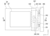
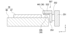
- the first moving body 532 is configured without a moving mirror, which simplifies the configuration of the stage moving device 507 and reduces the cost of manufacturing the first moving body 532 compared to the configuration of the fourth embodiment.
- the versatility of the stage moving device 507 can be improved.
- the position of the second moving body 34 in the X-axis direction, Y-axis direction, and ⁇ z direction relative to the first moving body 532 can be measured even in the case of without a moving mirror.
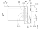
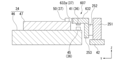
- the pair of interferometer heads 50 are attached, for example, to the plate holder 47 of the second moving body 34, and each faces the reflecting surface 632a in the Y axis direction.
- the second measurement system 37 has this interferometer head 50 and the reflecting surface 632a.
- the second measurement system 37 measures the position of the second moving body 34 in the Y axis direction and the ⁇ z direction relative to the first moving body 32.
- the control unit 8 moves the first moving body 632 stepwise in the Y-axis direction following the stepwise movement in the Y-axis direction of the second moving body 34 on which the exposure object P is placed. This controls the distance between the first moving body 632 and the second moving body 34 along the Y-axis direction to be constant.
- a sensor capable of measuring the height positions in the Z-axis direction of the first moving body 632 and the second moving body 34 relative to the optical base 5 may be provided separately.
- control unit 8 may control the position of the Z stage 253 in the Z direction based on the output result of the sensor that measures the height position in the Z-axis direction and the measurement result of the second measurement system 37 so that the distance between the first moving body 632 and the second moving body 34 along the Z-axis direction is constant.
- the X-encoder scale 41 and the reflecting surface 632a are provided on different surfaces of the first moving body 632, which increases the design freedom of the first moving body 632. As a result, the versatility of the stage moving device 607 can be increased.
- the first measurement system 36 has been described as having the X encoder scale 41 provided on the first moving body 32 and the X encoder head 45 provided on the second moving body 34, but is not limited thereto.
- the X encoder head 45 may be provided on the first moving body 32, and the X encoder scale 41 may be provided on the second moving body 34.
- the second measurement system 37 may acquire information about the distance between the first movable body 32 and the second movable body 34 using a reflecting surface 32a provided on one of the first movable body 32 and the second movable body 34 and at least one interferometer head 50 provided on the other of the first movable body 32 and the second movable body 34.
- a Y encoder head 44 may be provided on the base member 30, and a Y encoder scale 43 may be provided on the first movable body 32.
- the third measurement system 38 may measure the position of the first movable body 32 using a Y encoder scale 43 provided on one of the first movable body 32 and the base member 30, and at least one Y encoder head 44 provided on the other of the first movable body 32 and the base member 30.
Landscapes
- Physics & Mathematics (AREA)
- General Physics & Mathematics (AREA)
- Exposure And Positioning Against Photoresist Photosensitive Materials (AREA)
- Exposure Of Semiconductors, Excluding Electron Or Ion Beam Exposure (AREA)
- Container, Conveyance, Adherence, Positioning, Of Wafer (AREA)
Abstract
Description
本願は、2023年12月19日に出願された日本国特願2023-213947号に基づき優先権を主張し、その内容をここに援用する。
図1は、第1実施形態に係る露光装置1の構成を概略的に示す図である。図2は、第1実施形態に係る露光装置1の構成を概略的に示す外観斜視図である。
図1及び図2に示すように、露光装置1は、露光対象物Pに変調光を照射する装置である。特定の実施形態において、露光装置1は、液晶表示装置(フラットパネルディスプレイ)などに用いられる矩形(角型)のガラス基板を露光対象物とするステップ・アンド・スキャン方式の投影露光装置、いわゆるスキャナである。露光対象物であるガラス基板Pは、少なくとも一辺の長さ、または対角長が500mm以上であり、フラットパネルディスプレイ用の基板であってもよい。露光装置1によって露光された露光対象物P(例えば、フラットパネルディスプレイ用の基板)は、現像されることによって製品に供される。
以下において、照明光学装置6から露光対象物Pに向かって照射される光の光軸方向に平行な方向をZ軸方向(第3方向)とし、Z軸に直交する所定平面の方向をX軸方向(第1方向)とし、Z軸及びX軸とそれぞれ直交する方向をY軸方向(第2方向)とする三次元直交座標系を必要に応じて用いて説明する。なお、本実施形態では、露光動作時に露光対象物P(ガラス基板)が照明光学装置6の投影モジュール17に対して相対走査される方向をX軸方向とする。
架台部3は、露光装置1の基台であり、防振台2の上に設置される。架台部3は、ステージ移動装置7のうち露光対象物Pが載置されるステージ(第2移動体34)を、X軸方向及びY軸方向に移動可能に支持する。
図3に示すように、照明光学装置6は、照明モジュール16と、投影モジュール17(投影光学系)と、光源ユニット18と、光変調部20と、を備える。
照明モジュール16は、光学定盤5の上部に配置され、光ファイバ19を介して光源ユニット18に接続される。本実施形態の一例において、照明モジュール16には、第1照明モジュール16A、第2照明モジュール16B、第3照明モジュール16C及び第4照明モジュール16Dが含まれる。以下の説明において、第1照明モジュール16A~第4照明モジュール16Dを互いに区別しない場合には、これらを総称して照明モジュール16と記載する。
また、投影モジュール17は、投影部ともいう。投影モジュール17(投影部)は、光変調部20上のパターンの像を等倍で投影する等倍系であってもよく、拡大系または縮小系であってもよい。また、投影モジュール17は、単一もしくは2種の硝材(特に石英もしくは蛍石)により構成されることが好ましい。
図2、図4及び図5に示すように、光学定盤5よりも下方であって、架台部3の上部には、ステージ移動装置7が設けられている。ステージ移動装置7は、架台部3に取り付けられるベース部材30(図1及び2参照)と、ベース部材30に対して移動可能に構成された第1移動体32及び第2移動体34と、第1計測系36と、第2計測系37と、第3計測系38と、を有する。
図4、図5及び図7に示すように、第1移動体32は、例えばエンコーダ設置用の長尺部材である。第1移動体32は、例えば少なくとも一部に反射面32aを有する移動鏡である。第1移動体32は、X軸方向に沿って延在し、かつベース部材30に対してY軸方向に沿って移動する。なお、ベース部材30と光学定盤5とは互いに固定されているため、「ベース部材30に対して移動する」とは、「光学定盤5に対して移動する」と同義であってよい。図4及び図6では、説明のため第1移動体32が光学定盤5に対して移動可能に取り付けられた状態を例として図示している。
図4及び図6に示すように、第1移動体32は、後述する露光対象物Pが載置された第2移動体34のY軸方向へのステップ移動に追従して、Y軸方向へステップ移動する。これにより第1移動体32と第2移動体34とのY軸方向に沿う距離が一定となるように制御される。なお、第2移動体34がX方向にスキャンされている間は、第1移動体32は静止するように制御される。
露光装置1では、制御部8は、少なくとも第1移動体32及び第2移動体34の位置を制御する。例えば露光動作時などには、各計測系(第1計測系36及び第2計測系37を含む)の計測値に基づいて、第1移動体32及び第2移動体34の位置が制御部8によって管理される。なお、ウエハアライメント動作時にも各計測系の計測値に基づいて第1移動体32及び第2移動体34の位置を管理及び制御してもよい。
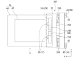
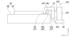
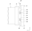
まず、本発明の第2実施形態について、図9から図11を用いて説明する。図9は、第2実施形態に係るステージ移動装置207の構成を模式的に示す平面図である。図10は、第2実施形態に係るステージ移動装置207の構成を模式的に示す正面図である。図10は、図9のX矢視図である。図11は、第2実施形態に係るステージ移動装置207の複数のエンコーダ計測系255,258の構成を模式的に示す平面図である。第2実施形態では、第1移動体32がZ軸方向にも移動可能に構成されている点及び第1計測系36の対向方向がZ軸方向である点で上述した第1実施形態と相違している。
ステージ移動装置207は第1のエンコーダ計測系255及び第2のエンコーダ計測系258を有するので、第1移動体32のZ軸方向駆動時におけるX軸方向及びY軸方向に関する斜め走りの誤差を監視できる。
尚、本実施形態において、第1移動体32に対する第2移動体34のθx方向の位置情報を計測するためのZチルト位置計測系(不図示)を別途設けてもよい。Zチルト位置計測系は、例えば第2移動体34に取り付けられた不図示の変位センサを用いた計測系等を用いることが可能である。
次に、本発明の第3実施形態について、図12及び図13を用いて説明する。図12は、第3実施形態に係るステージ移動装置307の構成を模式的に示す平面図である。図13は、第3実施形態に係るステージ移動装置307の構成を模式的に示す正面図である。図13は、図12のXIII-XIII線に沿う断面図である。第3実施形態では、第1移動体332として移動鏡以外の部材を用いる点で上述した各実施形態と相違している。尚、第3実施形態のステージ移動装置307の構成は、第1移動体332が移動鏡でない(反射面32aを有しない)点及び干渉計ヘッド50が設けられない点を除き、上記第2実施形態と概ね同じであるので、以下、相違点についてのみ説明し、第2実施形態と同じ構成又は機能を有する要素については、その説明を省略する。
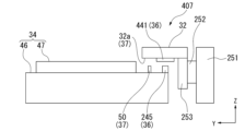
次に、本発明の第4実施形態について、図14及び図15を用いて説明する。図14は、第4実施形態に係るステージ移動装置407の構成を模式的に示す平面図である。図15は、第4実施形態に係るステージ移動装置407の構成を模式的に示す正面図である。図15は、図14のXV矢視図である。第4実施形態では、第1移動体32に2次元のエンコーダスケール441が取り付けられる点で上述した各実施形態と相違している。尚、第4実施形態のステージ移動装置407の構成は、エンコーダスケール441が2次元である点及び第1移動体32のエンコーダ計測系455がZ軸方向のみに設けられる点を除き、上記第2実施形態と概ね同じであるので、以下、相違点についてのみ説明し、第2実施形態と同じ構成又は機能を有する要素については、その説明を省略する。
次に、本発明の第5実施形態について、図16及び図17を用いて説明する。図16は、第5実施形態に係るステージ移動装置507の構成を模式的に示す平面図である。図17は、第5実施形態に係るステージ移動装置507の構成を模式的に示す正面図である。図17は、図16のXVII-XVII線に沿う断面図である。第5実施形態では、第4実施形態における第1移動体32を移動鏡レスに形成した点で上述した第4実施形態と相違している。尚、第5実施形態のステージ移動装置507の構成は、第1移動体532が移動鏡でない(反射面32aを有しない)点及び干渉計ヘッド50が設けられない点を除き、上記第4実施形態と概ね同じであるので、以下、相違点についてのみ説明し、第4実施形態と同じ構成又は機能を有する要素については、その説明を省略する。
次に、本発明の第6実施形態について、図18及び図19を用いて説明する。図18は、第6実施形態に係るステージ移動装置607の構成を模式的に示す平面図である。図19は、第6実施形態に係るステージ移動装置607の構成を模式的に示す正面図である。図19は、図18のXIX-XIX線に沿う断面図である。第6実施形態では、第1計測系36に用いられるXエンコーダスケール41と第2計測系37に用いられる反射面632aとが第1移動体632上の異なる面に設けられる点で上述した各実施形態と相違している。
第1移動体632は、X軸方向に延びるとともにYZ断面矩形状に形成された棒状部材である。第1移動体632の下面(-Z軸方向を向く面)には、X軸方向に沿って延びる1次元のXエンコーダスケール41が設けられている。第2移動体34上には、Xエンコーダスケール41と対向するように一対のXエンコーダヘッド45が設けられる。第1計測系36は、このXエンコーダスケール41とXエンコーダヘッド45とを有する。第1計測系36により、第1移動体32に対する第2移動体34のX軸方向の位置が計測される。
例えば、上述の第1実施形態では、第1計測系36は、第1移動体32に設けられたXエンコーダスケール41と、第2移動体34に設けられたXエンコーダヘッド45と、を有する構成について説明したが、これに限られない。第1移動体32にXエンコーダヘッド45が設けられ、第2移動体34にXエンコーダスケール41が設けられてもよい。換言すれば、第1計測系36は、第1移動体32及び第2移動体34の一方に設けられたXエンコーダヘッド45と、X軸方向に延在し、かつ、Xエンコーダヘッド45と対向するように第1移動体32及び第2移動体34の他方に設けられたXエンコーダスケール41と、を用いて第2移動体34の位置を計測してもよい。同様に、第2計測系37に関して、第1移動体32に干渉計ヘッド50が設けられ、第2移動体34に反射面32aが設けられてもよい。換言すれば、第2計測系37は、第1移動体32及び第2移動体34の一方に設けられた反射面32aと、第1移動体32及び第2移動体34の他方に設けられた少なくとも一つの干渉計ヘッド50と、を用いて、第1移動体32と第2移動体34との間隔に関する情報を取得してもよい。同様に、第3計測系38に関して、ベース部材30にYエンコーダヘッド44が設けられ、第1移動体32にYエンコーダスケール43が設けられてもよい。換言すれば、第3計測系38は、第1移動体32及びベース部材30の一方に設けられたYエンコーダスケール43と、第1移動体32及びベース部材30の他方に設けられた少なくとも一つのYエンコーダヘッド44と、を用いて、第1移動体32の位置を計測してもよい。
第1計測系36、第2計測系37及び第3計測系38は、光学定盤5を基準に第1移動体32及び第2移動体34の位置情報を求めるものであってもよい。露光装置1は、上述した第1計測系36、第2計測系37及び第3計測系38の他に複数の計測系を有してもよい。
リニアエンコーダシステムの計測系に用いられるエンコーダヘッド(例えばXエンコーダヘッド45やXYエンコーダヘッド245)は、光源からのビームをエンコーダスケールに照射する光学系の全てを有している必要はなく、光学系の一部、例えば射出部のみを有するものとしてもよい。
Claims (32)
- 第1方向に延在し、かつ、前記第1方向と交差する第2方向に移動する第1移動体と、 前記第2方向に移動する第2移動体と、
前記第1移動体及び前記第2移動体の一方に設けられた第1ヘッドと、前記第1方向に延在し、かつ、前記第1ヘッドと対向するように前記第1移動体及び前記第2移動体の他方に設けられたスケールと、を用いて前記第2移動体の前記第1方向に関する位置を計測する第1計測系と、
前記第1移動体と前記第2移動体との間の間隔に関する情報を取得する第2計測系と、 を備える移動装置。 - 前記第2計測系の計測結果に基づいて前記間隔を制御する請求項1に記載の移動装置。
- 前記第2移動体の前記第2方向への移動に伴い、前記第1移動体は前記第2方向に移動する請求項1又は2に記載の移動装置。
- 前記第1ヘッドは前記第2移動体に設けられ、
前記スケールは前記第1移動体に設けられている請求項1~3のいずれか一項に記載の移動装置。 - 前記第2移動体は、前記第1方向に移動可能であり、
前記第1計測系の計測結果に基づいて前記第1方向における前記第2移動体の位置を制御する請求項1~4のいずれか一項に記載の移動装置。 - 前記第1計測系は、前記スケールよりも熱膨張率が小さいテーブルに設けられて前記第1方向に並ぶ複数の前記第1ヘッドを含む請求項1~5のいずれか一項に記載の移動装置。
- ストッパーをさらに備え、
前記ストッパーと前記第1ヘッドとの間の距離は、前記スケールと前記第1ヘッドとの間の距離よりも小さい請求項1~6のいずれか一項に記載の移動装置。 - 前記第2計測系は、干渉計システムを含む請求項1~7のいずれか一項に記載の移動装置。
- 前記第2計測系は、前記第1方向の複数位置で、前記間隔に関する情報を取得する請求項1~8のいずれか一項に記載の移動装置。
- 前記第2計測系は、前記第1移動体及び前記第2移動体の一方に設けられた第1計測部材と、前記第1移動体と前記第2移動体の他方に設けられた少なくとも一つの第2ヘッドと、を用いて、前記間隔に関する情報を取得する請求項1~9のいずれか一項に記載の移動装置。
- 前記第2計測系は、前記第1移動体に設けられた前記第1計測部材と、前記第2移動体に設けられた少なくとも一つの前記第2ヘッドと、を用いて、前記間隔に関する情報を取得する請求項10に記載の移動装置。
- 前記第1計測部材及び前記スケールは、前記第1移動体に設けられ、
前記第1ヘッド及び前記少なくとも一つの第2ヘッドは、前記第2移動体に設けられている請求項11に記載の移動装置。 - 前記第1計測部材及び前記スケールは、前記第1移動体の同じ側に設けられている請求項12に記載の移動装置。
- 前記第2方向において、前記第1ヘッドは前記スケールに対向し、
前記第2方向において、前記少なくとも1つの第2ヘッドは前記第1計測部材に対向する請求項10~13のいずれか一項に記載の移動装置。 - 前記第2計測系は、前記第2方向において、前記間隔に関する情報を取得し、
前記第2計測系を用いて取得された前記間隔に関する情報に基づいて、前記第2方向における前記第2移動体の位置を制御する請求項1~14のいずれか一項に記載の移動装置。 - 前記第2計測系は、前記第1移動体と前記第2移動体との間の、前記第1方向及び前記第2方向と交差する第3方向における前記間隔に関する情報を取得する請求項1~13のいずれか一項に記載の移動装置。
- 前記第3方向おいて、前記第1ヘッドは前記スケールに対向する請求項16に記載の移動装置。
- 前記第1移動体の前記第2方向に関する位置を計測する第3計測系をさらに含み、
前記第2計測系の計測結果と前記第3計測系の計測結果とに基づいて、前記第2方向における前記第2移動体の位置を制御する請求項15に記載の移動装置。 - 第1方向に延在し、かつ、前記第1方向と交差する第2方向に移動する第1移動体と、 前記第2方向に移動する第2移動体と、
前記第1移動体及び前記第2移動体の一方に設けられた第1ヘッドと、前記第1方向に延在し、かつ、前記第1ヘッドと対向するように前記第1移動体及び前記第2移動体の他方に設けられたスケールと、を用いて前記第2移動体の前記第1方向に関する位置を計測する第1計測系と、
前記第1移動体及び前記第2移動体の前記第2方向における位置関係に関する情報を取得する第2計測系と、
前記第1移動体の前記第2方向に関する位置を計測する第3計測系と、
を備え、
前記第1計測系、前記第2計測系及び前記第3計測系の計測結果に基づいて、前記第1方向及び前記第2方向における前記第2移動体の位置を制御する移動装置。 - 前記第1移動体の第2方向に関する位置を計測する第3計測系をさらに含む請求項1~16のいずれか一項に記載の移動装置。
- 前記第3計測系の計測結果に基づいて、前記第2方向における前記第1移動体の位置を制御する請求項20の移動装置。
- ベース部材をさらに備え、
前記第3計測系は、前記第1移動体及び前記ベース部材の一方に設けられた第3ヘッドと、前記第3ヘッドと対向するように前記第1移動体及び前記ベース部材の他方に設けられた第2計測部材と、を用いて前記第1移動体の前記第2方向に関する位置を計測する請求項18~21のいずれか一項に記載の移動装置。 - 前記スケールを構成する格子線の補正情報に基づいて、前記第1移動体の移動を制御する請求項1~22のいずれか一項に記載の移動装置。
- 請求項22に記載の移動装置と、
前記ベース部材に支持された光学系と、を備え、
前記第2移動体に保持された物体に対して前記光学系からの光を照射し、前記物体を露光する露光装置。 - 請求項1~23のいずれか一項に記載の移動装置と、
光学系と、を備え、
前記第2移動体に保持された物体に対して前記光学系からの光を照射し、前記物体を露光する露光装置。 - 前記物体を保持した前記第2移動体を前記第1方向に移動させながら、前記光学系からの光で前記物体を露光する請求項24又は25に記載の露光装置。
- 前記物体の第1ショット領域を前記光学系からの光で露光した後、前記物体を保持した前記第2移動体を前記第2方向に移動させ、その後、前記物体において前記第2方向に前記第1ショット領域と並ぶ第2ショット領域を前記光学系からの光で露光する請求項24~26のいずれか一項に記載の露光装置。
- 前記光学系は、前記第2方向に並んだ複数の投影光学系を含み、
前記第2移動体の前記第2方向における移動可能範囲は、前記第2移動体の前記第1方向における移動可能範囲よりも小さい請求項24~27のいずれか一項に記載の露光装置。 - 第1方向に延在し、かつ、前記第1方向と交差する第2方向に移動する第1移動体と、前記第2方向に移動する第2移動体と、をそれぞれ移動させる移動体の駆動方法であって、
前記第1移動体及び前記第2移動体の一方に設けられた第1ヘッドと、前記第1方向に延在し、かつ、前記第1ヘッドと対向するように前記第1移動体及び前記第2移動体の他方に設けられたスケールと、を用いて前記第2移動体の前記第1方向に関する位置を計測することと、
前記第1移動体と前記第2移動体との間の間隔に関する情報を取得することと、
前記第2移動体に関する計測結果と前記間隔に関する情報とに基づいて前記第1移動体及び前記第2移動体を駆動させることと、
を含む移動体の駆動方法。 - 第1方向に延在し、かつ、前記第1方向と交差する第2方向に移動する第1移動体と、前記第2方向に移動する第2移動体と、をそれぞれ移動させる移動体の駆動方法であって、
前記第1移動体及び前記第2移動体の一方に設けられた第1ヘッドと、前記第1方向に延在し、かつ、前記第1ヘッドと対向するように前記第1移動体及び前記第2移動体の他方に設けられたスケールと、を用いて前記第2移動体の前記第1方向に関する位置を計測することと、
前記第1移動体及び前記第2移動体の前記第2方向における位置関係に関する情報を取得することと、
前記第1移動体の前記第2方向に関する位置を計測することと、
計測された前記第2移動体の前記第1方向に関する位置と、取得された前記第1移動体及び前記第2移動体の前記位置関係に関する情報と、計測された前記第1移動体の前記第2方向に関する位置と、に基づいて、前記第1方向及び前記第2方向における前記第2移動体の位置を制御することと、
を含む移動体の駆動方法。 - 第1方向に延在し、かつ、前記第1方向と交差する第2方向に移動する第1移動体と、前記第2方向に移動する第2移動体と、前記第2移動体に保持された物体と、前記物体に光を照射する光学系と、を備える露光装置を用いて物体を露光する露光方法であって、 前記第1移動体及び前記第2移動体の一方に設けられた第1ヘッドと、前記第1方向に延在し、かつ、前記第1ヘッドと対向するように前記第1移動体及び前記第2移動体の他方に設けられたスケールと、を用いて前記第2移動体の前記第1方向に関する位置を計測することと、
前記第1移動体と前記第2移動体との間の間隔に関する情報を取得することと、
前記第2移動体に関する計測結果と前記間隔に関する情報とに基づいて前記第1移動体及び前記第2移動体の移動を制御することと、
前記物体を保持した前記第2移動体を前記第1方向に移動させながら、前記光学系からの光で前記物体を露光することと、
を含む露光方法。 - 請求項24~28のいずれか一項に記載の露光装置を用いて基板を露光することと、
露光された前記基板を現像することと、
を含むデバイス製造方法。
Priority Applications (3)
| Application Number | Priority Date | Filing Date | Title |
|---|---|---|---|
| KR1020267019844A KR20260116199A (ko) | 2023-12-19 | 2024-12-09 | 이동 장치, 노광 장치, 이동체의 구동 방법, 노광 방법 및 디바이스 제조 방법 |
| CN202480079962.2A CN122422825A (zh) | 2023-12-19 | 2024-12-09 | 移动装置、曝光装置、移动体的驱动方法、曝光方法及器件制造方法 |
| JP2025565258A JPWO2025134841A1 (ja) | 2023-12-19 | 2024-12-09 |
Applications Claiming Priority (2)
| Application Number | Priority Date | Filing Date | Title |
|---|---|---|---|
| JP2023-213947 | 2023-12-19 | ||
| JP2023213947 | 2023-12-19 |
Publications (1)
| Publication Number | Publication Date |
|---|---|
| WO2025134841A1 true WO2025134841A1 (ja) | 2025-06-26 |
Family
ID=96136893
Family Applications (1)
| Application Number | Title | Priority Date | Filing Date |
|---|---|---|---|
| PCT/JP2024/043468 Pending WO2025134841A1 (ja) | 2023-12-19 | 2024-12-09 | 移動装置、露光装置、移動体の駆動方法、露光方法及びデバイス製造方法 |
Country Status (5)
| Country | Link |
|---|---|
| JP (1) | JPWO2025134841A1 (ja) |
| KR (1) | KR20260116199A (ja) |
| CN (1) | CN122422825A (ja) |
| TW (1) | TW202543024A (ja) |
| WO (1) | WO2025134841A1 (ja) |
Citations (4)
| Publication number | Priority date | Publication date | Assignee | Title |
|---|---|---|---|---|
| JP2010510672A (ja) * | 2006-11-15 | 2010-04-02 | ザイゴ コーポレーション | リソグラフィツールにおいて使用される距離測定干渉計及びエンコーダ測定システム |
| JP2010192593A (ja) * | 2009-02-17 | 2010-09-02 | Nikon Corp | 露光装置及び露光方法、並びにデバイス製造システム |
| JP2012208937A (ja) * | 2006-01-19 | 2012-10-25 | Nikon Corp | 移動体駆動方法及び移動体駆動システム、パターン形成方法及びパターン形成装置、露光方法及び露光装置、並びにデバイス製造方法 |
| JP2016186570A (ja) * | 2015-03-27 | 2016-10-27 | 株式会社ニコン | 移動体装置、露光装置、フラットパネルディスプレイの製造方法、及びデバイス製造方法 |
-
2024
- 2024-12-09 WO PCT/JP2024/043468 patent/WO2025134841A1/ja active Pending
- 2024-12-09 CN CN202480079962.2A patent/CN122422825A/zh active Pending
- 2024-12-09 JP JP2025565258A patent/JPWO2025134841A1/ja active Pending
- 2024-12-09 KR KR1020267019844A patent/KR20260116199A/ko active Pending
- 2024-12-10 TW TW113147905A patent/TW202543024A/zh unknown
Patent Citations (4)
| Publication number | Priority date | Publication date | Assignee | Title |
|---|---|---|---|---|
| JP2012208937A (ja) * | 2006-01-19 | 2012-10-25 | Nikon Corp | 移動体駆動方法及び移動体駆動システム、パターン形成方法及びパターン形成装置、露光方法及び露光装置、並びにデバイス製造方法 |
| JP2010510672A (ja) * | 2006-11-15 | 2010-04-02 | ザイゴ コーポレーション | リソグラフィツールにおいて使用される距離測定干渉計及びエンコーダ測定システム |
| JP2010192593A (ja) * | 2009-02-17 | 2010-09-02 | Nikon Corp | 露光装置及び露光方法、並びにデバイス製造システム |
| JP2016186570A (ja) * | 2015-03-27 | 2016-10-27 | 株式会社ニコン | 移動体装置、露光装置、フラットパネルディスプレイの製造方法、及びデバイス製造方法 |
Also Published As
| Publication number | Publication date |
|---|---|
| JPWO2025134841A1 (ja) | 2025-06-26 |
| TW202543024A (zh) | 2025-11-01 |
| KR20260116199A (ko) | 2026-07-28 |
| CN122422825A (zh) | 2026-07-17 |
Similar Documents
| Publication | Publication Date | Title |
|---|---|---|
| US10191383B2 (en) | Exposure apparatus, exposure method, and device manufacturing method | |
| TWI451203B (zh) | A moving body driving system, a pattern forming apparatus, an exposure apparatus and an exposure method, and an element manufacturing method | |
| JP5071894B2 (ja) | ステージ装置、パターン形成装置、露光装置、ステージ駆動方法、露光方法、並びにデバイス製造方法 | |
| TWI548953B (zh) | A moving body system and a moving body driving method, a pattern forming apparatus and a pattern forming method, an exposure apparatus and an exposure method, and an element manufacturing method | |
| JP7047876B2 (ja) | 移動体装置、移動方法、露光装置、露光方法、フラットパネルディスプレイの製造方法、並びにデバイス製造方法 | |
| KR101476865B1 (ko) | 노광 장치와 노광 방법, 및 디바이스 제조 방법 | |
| JP7028289B2 (ja) | 移動体装置、露光装置、及びフラットパネルディスプレイ製造方法 | |
| JP6787404B2 (ja) | 移動体装置、移動方法、露光装置、露光方法、フラットパネルディスプレイの製造方法、並びにデバイス製造方法 | |
| TW202543024A (zh) | 移動裝置、曝光裝置、移動體的驅動方法、曝光方法及元件製造方法 | |
| JP5757397B2 (ja) | 露光方法及び露光装置、並びにデバイス製造方法 | |
| JP5612810B2 (ja) | 露光装置及び露光方法、並びにデバイス製造方法 | |
| JP2006349488A (ja) | 干渉計システム、ステージ装置、露光装置、及びデバイス製造方法 | |
| JP2022191012A (ja) | 異物検査装置の調整方法、露光装置、および物品製造方法 | |
| JP2023057858A (ja) | マーク検出装置、露光装置および物品製造方法 | |
| WO2010143652A1 (ja) | 露光方法及び装置、並びにデバイス製造方法 | |
| HK1136864A (en) | Moving body driving system, pattern forming apparatus, exposure apparatus, exposure method and device manufacturing method |
Legal Events
| Date | Code | Title | Description |
|---|---|---|---|
| 121 | Ep: the epo has been informed by wipo that ep was designated in this application |
Ref document number: 24907226 Country of ref document: EP Kind code of ref document: A1 |
|
| ENP | Entry into the national phase |
Ref document number: 2025565258 Country of ref document: JP Kind code of ref document: A |
|
| ENP | Entry into the national phase |
Ref document number: 1020267019844 Country of ref document: KR Free format text: ST27 STATUS EVENT CODE: A-0-1-A10-A15-NAP-PA0105 (AS PROVIDED BY THE NATIONAL OFFICE) |
|
| WWE | Wipo information: entry into national phase |
Ref document number: 1020267019844 Country of ref document: KR |
|
| WWP | Wipo information: published in national office |
Ref document number: 1020267019844 Country of ref document: KR |