WO2025134530A1 - 電気自動車及び電気自動車を制御するプログラム - Google Patents
電気自動車及び電気自動車を制御するプログラム Download PDFInfo
- Publication number
- WO2025134530A1 WO2025134530A1 PCT/JP2024/037993 JP2024037993W WO2025134530A1 WO 2025134530 A1 WO2025134530 A1 WO 2025134530A1 JP 2024037993 W JP2024037993 W JP 2024037993W WO 2025134530 A1 WO2025134530 A1 WO 2025134530A1
- Authority
- WO
- WIPO (PCT)
- Prior art keywords
- electric vehicle
- pseudo
- shifter
- sequential
- virtual
- Prior art date
- Legal status (The legal status is an assumption and is not a legal conclusion. Google has not performed a legal analysis and makes no representation as to the accuracy of the status listed.)
- Pending
Links
Images


Classifications
-
- B—PERFORMING OPERATIONS; TRANSPORTING
- B60—VEHICLES IN GENERAL
- B60L—PROPULSION OF ELECTRICALLY-PROPELLED VEHICLES; SUPPLYING ELECTRIC POWER FOR AUXILIARY EQUIPMENT OF ELECTRICALLY-PROPELLED VEHICLES; ELECTRODYNAMIC BRAKE SYSTEMS FOR VEHICLES IN GENERAL; MAGNETIC SUSPENSION OR LEVITATION FOR VEHICLES; MONITORING OPERATING VARIABLES OF ELECTRICALLY-PROPELLED VEHICLES; ELECTRIC SAFETY DEVICES FOR ELECTRICALLY-PROPELLED VEHICLES
- B60L15/00—Methods, circuits, or devices for controlling the traction-motor speed of electrically-propelled vehicles
-
- B—PERFORMING OPERATIONS; TRANSPORTING
- B60—VEHICLES IN GENERAL
- B60L—PROPULSION OF ELECTRICALLY-PROPELLED VEHICLES; SUPPLYING ELECTRIC POWER FOR AUXILIARY EQUIPMENT OF ELECTRICALLY-PROPELLED VEHICLES; ELECTRODYNAMIC BRAKE SYSTEMS FOR VEHICLES IN GENERAL; MAGNETIC SUSPENSION OR LEVITATION FOR VEHICLES; MONITORING OPERATING VARIABLES OF ELECTRICALLY-PROPELLED VEHICLES; ELECTRIC SAFETY DEVICES FOR ELECTRICALLY-PROPELLED VEHICLES
- B60L15/00—Methods, circuits, or devices for controlling the traction-motor speed of electrically-propelled vehicles
- B60L15/20—Methods, circuits, or devices for controlling the traction-motor speed of electrically-propelled vehicles for control of the vehicle or its driving motor to achieve a desired performance, e.g. speed, torque, programmed variation of speed
-
- F—MECHANICAL ENGINEERING; LIGHTING; HEATING; WEAPONS; BLASTING
- F16—ENGINEERING ELEMENTS AND UNITS; GENERAL MEASURES FOR PRODUCING AND MAINTAINING EFFECTIVE FUNCTIONING OF MACHINES OR INSTALLATIONS; THERMAL INSULATION IN GENERAL
- F16H—GEARING
- F16H59/00—Control inputs to control units of change-speed- or reversing-gearings for conveying rotary motion
- F16H59/36—Inputs being a function of speed
- F16H59/44—Inputs being a function of speed dependent on machine speed, e.g. the vehicle speed
-
- F—MECHANICAL ENGINEERING; LIGHTING; HEATING; WEAPONS; BLASTING
- F16—ENGINEERING ELEMENTS AND UNITS; GENERAL MEASURES FOR PRODUCING AND MAINTAINING EFFECTIVE FUNCTIONING OF MACHINES OR INSTALLATIONS; THERMAL INSULATION IN GENERAL
- F16H—GEARING
- F16H59/00—Control inputs to control units of change-speed- or reversing-gearings for conveying rotary motion
- F16H59/50—Inputs being a function of the status of the machine, e.g. position of doors or safety belts
- F16H59/58—Inputs being a function of the status of the machine, e.g. position of doors or safety belts dependent on signals from the steering
-
- F—MECHANICAL ENGINEERING; LIGHTING; HEATING; WEAPONS; BLASTING
- F16—ENGINEERING ELEMENTS AND UNITS; GENERAL MEASURES FOR PRODUCING AND MAINTAINING EFFECTIVE FUNCTIONING OF MACHINES OR INSTALLATIONS; THERMAL INSULATION IN GENERAL
- F16H—GEARING
- F16H61/00—Control functions within control units of change-speed- or reversing-gearings for conveying rotary motion ; Control of exclusively fluid gearing, friction gearing, gearings with endless flexible members or other particular types of gearing
- F16H61/02—Control functions within control units of change-speed- or reversing-gearings for conveying rotary motion ; Control of exclusively fluid gearing, friction gearing, gearings with endless flexible members or other particular types of gearing characterised by the signals used
-
- G—PHYSICS
- G10—MUSICAL INSTRUMENTS; ACOUSTICS
- G10K—SOUND-PRODUCING DEVICES; METHODS OR DEVICES FOR PROTECTING AGAINST, OR FOR DAMPING, NOISE OR OTHER ACOUSTIC WAVES IN GENERAL; ACOUSTICS NOT OTHERWISE PROVIDED FOR
- G10K15/00—Acoustics not otherwise provided for
- G10K15/04—Sound-producing devices
Definitions
- This disclosure relates to technology for controlling electric vehicles that have electric motors as their driving sources.
- JP 2021-151168 A discloses a conventional technology relating to an electric vehicle that can simulate the manual shifting operation of a vehicle equipped with a manual transmission powered by an internal combustion engine (hereinafter referred to as a manual-shift internal combustion engine vehicle) by controlling an electric motor.
- the driver of the electric vehicle can select from multiple virtual gear modes (virtual shift positions) using a paddle switch or the like.
- the paddle switch is a shift device that simulates a sequential shifter provided on the steering wheel (hereinafter referred to as a pseudo-sequential shifter).
- the above-mentioned conventional technology allows the driver to experience the shifting operation of a manually-shifted internal combustion engine vehicle in an electric vehicle.
- the driver can then use the pseudo-sequential shifter to select a virtual shift position that replicates the shift position of a manually-shifted internal combustion engine vehicle.
- the pseudo-sequential shifter is attached to the steering wheel, turning the steering wheel significantly to turn the electric vehicle changes the positional relationship between the hands on the steering wheel and the pseudo-sequential shifter.
- the steering angle of the steering wheel is large, it becomes difficult for the driver to smoothly operate the pseudo-sequential shifter.
- One objective of this disclosure is to provide an electric vehicle capable of reproducing the shifting operations of a manual transmission internal combustion engine vehicle, which allows the driver to select a mode in which the driver can experience operating a manual transmission internal combustion engine vehicle, and which can improve the ease of driving in that mode.
- the present disclosure provides an electric vehicle having an electric motor as a drive source.
- the electric vehicle includes an accelerator pedal used for driving, a pseudo-sequential shifter, and a control device that controls the electric vehicle in response to the operation of the accelerator pedal.
- the pseudo-sequential shifter is an operating member installed on the steering wheel that simulates a sequential shifter used for shifting gears in a manually variable internal combustion engine vehicle.
- the control device is configured to perform the following: The first is to execute a manual mode, which is one of the control modes, at the driver's selection. In the manual mode, the operation of the pseudo-sequential shifter is associated with a virtual shift position, which is a virtual shift position.
- the opening degree of the accelerator pedal, the virtual shift position, and the vehicle speed of the electric vehicle are associated with the torque of the electric motor.
- the second is to automatically upshift the virtual shift position in response to the vehicle speed of the electric vehicle when the steering angle of the steering wheel becomes equal to or greater than a predetermined angle while the manual mode is being executed.
- the pseudo-sequential shifter may be mounted on a steering wheel.
- the pseudo-sequential shifter may be mounted on a steering column.
- the opening degree of the accelerator pedal, the virtual shift position, and the vehicle speed of the electric vehicle are associated with the torque of the electric motor.
- the second is to automatically upshift the virtual shift position in response to the vehicle speed of the electric vehicle when the steering angle of the steering wheel becomes equal to or greater than a predetermined angle while the manual mode is being executed.
- FIG. 1 is a diagram illustrating a configuration of an electric vehicle according to an embodiment of the present disclosure.
- FIG. 1 is a diagram showing an example of a pseudo sequential shifter provided on a steering wheel.
- 1A and 1B are diagrams illustrating an example of a pseudo-sequential shifter provided on a steering column.
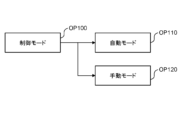
- FIG. 2 is a tree diagram showing an example of electric vehicle control modes selectable by the control device.
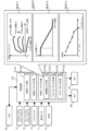
- FIG. 2 is a diagram showing the configuration of a control device related to driving control of an electric vehicle.
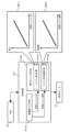
- FIG. 2 is a diagram showing the configuration of a control device related to sound control of an electric vehicle.
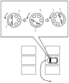
- FIG. 2 is a conceptual diagram showing an example of a situation in which an automatic upshift is performed by the electric vehicle according to the present embodiment.
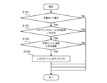
- FIG. 4 is a flow chart showing an example of processing by the electric vehicle according to the present embodiment.
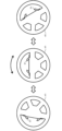
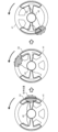
- 11A and 11B are diagrams illustrating how a steering wheel rotates when a pseudo-sequential shifter is provided on a steering column. 4 is a graph for explaining the timing at which an automatic upshift is performed by the electric vehicle according to the present embodiment.
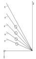
- FIG. 11A and 11B are diagrams illustrating how a steering wheel rotates when a pseudo-sequential shifter is provided on a steering column. 4 is a graph for explaining the timing at which an automatic upshift is performed by the electric vehicle according to the present embodiment.
- Fig. 1 is a diagram showing a schematic configuration of an electric vehicle 100 according to an embodiment of the present disclosure. First, the configuration of the power system of the electric vehicle 100 will be described with reference to Fig. 1.
- the electric vehicle 100 is equipped with two electric motors (M) 4F, 4R at the front and rear as a power source for driving.
- the electric motors 4F, 4R are, for example, three-phase AC motors.
- the front electric motor 4F is connected to a front drive shaft 5F that drives the front wheels 6F.
- the rear electric motor 4R is connected to a rear drive shaft 5R that drives the rear wheels 6R.
- the front wheels 6F are suspended on independent left and right electronically controlled front suspensions 7F.
- the rear wheels 6R are suspended on independent left and right electronically controlled rear suspensions 7R.
- Inverters (INV) 3F and 3R are attached to the front electric motor 4F and the rear electric motor 4R, respectively.
- the front inverter 3F and the rear inverter 3R are each connected to a battery (BATT) 2.
- the battery 2 stores electric energy to drive the electric motors 4F and 4R.
- the electric vehicle 100 is a battery electric vehicle (BEV) that runs on electric energy stored in the battery 2.
- the inverters 3F and 3R are, for example, voltage-type inverters, and control the torque of the electric motors 4F and 4R by PWM control.
- the electric vehicle 100 is equipped with a battery management system (BMS) 10.
- BMS battery management system
- the battery management system 10 is a device that monitors the cell voltage, current, temperature, etc. of the battery 2.
- the battery management system 10 has a function of estimating the state of charge (SOC) of the battery 2.
- the electric vehicle 100 is equipped with a vehicle speed sensor 11. At least one of the wheel speed sensors (not shown) provided on each of the left and right front wheels 6F and the left and right rear wheels 6R is used as the vehicle speed sensor 11.
- the electric vehicle 100 is also equipped with an accelerator pedal stroke sensor 12.
- the accelerator pedal stroke sensor 12 is provided on the accelerator pedal 22, and outputs a signal indicating the amount of depression of the accelerator pedal 22, i.e., the accelerator opening.
- the electric vehicle 100 is also equipped with a brake pedal stroke sensor 13.
- the brake pedal stroke sensor 13 is provided on the brake pedal 23, and outputs a signal indicating the amount of depression of the brake pedal 23, i.e., the brake opening.
- the electric vehicle 100 is also equipped with a steering angle sensor 14.
- the steering angle sensor 14 is provided on the steering wheel 24, and outputs a signal indicating the steering angle of the steering wheel 24, i.e., the rotation angle of the steering wheel.
- the accelerator pedal 22, brake pedal 23, and steering wheel 24 are driving operation members used to drive the electric vehicle 100.
- the electric vehicle 100 is equipped with pseudo-gear shift operation members that imitate operation members used to change gears in a manually-shifted internal combustion engine vehicle.
- the pseudo-gear shift operation members include at least the following pseudo-sequential shifter 25.
- the pseudo-sequential shifter 25 is provided on the steering wheel 24.
- An example of the pseudo-sequential shifter 25 is shown in FIG. 2 and FIG. 3.
- FIG. 2 shows a pseudo paddle shifter 51 attached to the steering wheel 41 as an example of the pseudo sequential shifter 25.
- the pseudo paddle shifter 51 is a dummy that is different from an original paddle shifter fixed to the steering wheel, which is a type of sequential shifter.
- the pseudo paddle shifter 51 consists of a pair of paddles that have a structure similar to shift paddles attached to the steering wheel, and the left and right paddles can be moved independently. Since the pseudo paddle shifter 51 is fixed to the steering wheel 41, when the steering wheel 41 rotates, the pseudo paddle shifter 51 also rotates together with the steering wheel 41.
- the pseudo paddle shifter 51 is provided with a shift switch 15 (see FIG. 1).
- the shift switch 15 outputs an upshift signal when the right paddle is pulled, and outputs a downshift signal when the left paddle is pulled.
- the left paddle may correspond to an upshift signal
- the right paddle may correspond to a downshift signal.
- the shift positions that are shifted up or down by the signal from the shift switch 15 are virtual shift positions.
- Figure 3 shows a pseudo paddle shifter 52 attached to the steering column (steering shaft) 42 as an example of a pseudo sequential shifter 25.
- the pseudo paddle shifter 52 is a dummy that is different from a real paddle shifter that is fixed to the steering column.
- the pseudo paddle shifter 52 consists of a pair of paddles that have a structure similar to shift paddles attached to the steering column, and the left and right paddles can be moved independently. Because the pseudo paddle shifter 52 is fixed to the steering column 42, the position of the pseudo paddle shifter 52 does not change even if the steering wheel 41 is rotated.
- the pseudo paddle shifter 52 is provided with a shift switch 15 (see FIG. 1). When the right paddle is pulled, an upshift signal is output from the shift switch 15, and when the left paddle is pulled, a downshift signal is output from the shift switch 15.
- the left paddle may correspond to an upshift signal
- the right paddle may correspond to a downshift signal.
- the pseudo-sequential shifter 25 may be a button installed on the steering wheel 41.
- one button is provided on each side of the steering wheel 41, and when the right button is pressed, the shift switch 15 outputs an upshift signal, and when the left button is pressed, the shift switch 15 outputs a downshift signal.
- the electric vehicle 100 is equipped with a human-machine interface (HMI) 20 as an interface with the driver, and an in-vehicle speaker 21.
- HMI human-machine interface
- the HMI 20 is equipped with a touch panel display.
- the HMI 20 displays information on the touch panel display, and accepts input from the driver via touch operations on the touch panel display.
- the in-vehicle speaker 21 provides information to the driver by voice, and is also capable of outputting a simulated engine sound, which will be described later.
- the electric vehicle 100 is equipped with a control device 101.
- the sensors and devices to be controlled mounted on the electric vehicle 100 are connected to the control device 101 via an in-vehicle network.
- vehicle speed sensor 11, accelerator pedal stroke sensor 12, brake pedal stroke sensor 13, steering angle sensor 14, and shift switch 15 various other sensors are also mounted on the electric vehicle 100.
- the control device 101 is typically an electronic control unit (ECU).
- the control device 101 may be a combination of multiple ECUs.
- the control device 101 has at least a processor 102 and a memory 103.
- the memory 103 includes a RAM for temporarily recording data, and a ROM for storing a program 104 executable by the processor 102 and various data 105 related to the program.
- the program 104 is composed of multiple instructions.
- the processor 102 reads and executes the program 104 and data 105 from the memory 103, and generates control signals based on signals obtained from each sensor.
- the control device 101 may have one or more processors 102.
- control device 101 controls the electric vehicle 100, including at least an automatic mode and a manual mode.
- the driver can select a control mode by touching the touch panel display of the HMI 20.
- one or more programs 104 associated with each touch operation are read from the memory 103 and executed by the processor 102.
- control modes of the electric vehicle 100 by the control device 101 that the driver can select by operating the HMI 20, and the driving control and sound control of the electric vehicle 100 related to the control modes.
- FIG. 4 is a tree diagram showing an example of the control modes of the electric vehicle 100 that can be selected by the control device 101.
- a selection screen is displayed on the touch panel display according to the control tree shown in FIG.
- the initial screen of the HMI 20 displays an option "control mode” OP100.
- an option “automatic mode” OP110 and an option “manual mode” OP120 are displayed on the touch panel display.
- the control mode of the electric vehicle 100 switches to automatic mode.
- Automatic mode is a control mode for driving the electric vehicle 100 as a normal BEV. In automatic mode, the driver can basically drive the electric vehicle 100 by only operating the accelerator pedal 22, brake pedal 23, and steering wheel 41. In automatic mode, the shift operation of the pseudo sequential shifter 25 is disabled.
- Manual mode is a control mode for operating the electric vehicle 100 like a manual transmission internal combustion engine vehicle.
- the driver performs shifting operations using the pseudo sequential shifter 25.
- the operation when the gear ratio of a manual transmission is changed is reproduced by the shifting operation of the pseudo sequential shifter 25.
- the clutch operation in a real sequential shift type manual transmission is performed automatically by a robot. Therefore, even in the manual mode of the electric vehicle 100, the clutch opening is calculated automatically. Note that since the electric vehicle 100 does not have an actual clutch, the clutch opening calculated in manual mode is a virtual clutch opening.
- the manual mode may further include multiple control modes.
- the control modes selectable by the driver may include, for example, a control mode related to a drive mode such as four-wheel drive or rear-wheel drive, and a control mode related to the type of engine sound reproduced by the electric vehicle 100.
- FIG. 5 is a diagram showing the configuration of the control device 101 related to the driving control of the electric vehicle 100. In detail, the configuration particularly related to torque control among driving control is shown.
- the processor 102 executes one or more driving control programs 104 stored in the memory 103, whereby the processor 102 functions as a driving control device.
- the control device 101 which functions as a driving control device, receives a control mode signal from the HMI 20.
- the control mode signal includes information about the control mode selected by the driver.
- the control device 101 executes process P110 based on the control mode signal.
- process P110 the control mode is switched in accordance with the control mode signal.
- the control mode switching that particularly affects driving control is the switch between automatic mode and manual mode.
- control device 101 executes process P120 for torque calculation in the automatic mode.
- process P120 the control device 101 obtains the vehicle speed from the signal of the vehicle speed sensor 11, and obtains the accelerator opening from the signal of the accelerator pedal stroke sensor 12.
- the control device 101 has a motor torque map with the accelerator opening and vehicle speed as parameters.
- the control device 101 inputs the vehicle speed and accelerator opening into the motor torque map, and controls the inverters 3F, 3R to generate the torque obtained from the motor torque map in the electric motors 4F, 4R.
- Process P130 When the control mode is switched to the manual mode, the control device 101 executes process P130 for calculating torque in the manual mode.
- Process P130 includes process P131 for calculating the torque to be generated at the drive wheels.
- Process P130 also includes process P132 and process P133.
- Process P132 is a process for calculating the torque to be generated at the front electric motor 4F
- process P133 is a process for calculating the torque to be generated at the rear electric motor 4R.
- Process P132 and process P133 are executed according to the drive wheel torque calculated in process P130 and the torque distribution between the front wheels 6F and the rear wheels 6R.
- Vehicle model MOD01 is used to calculate the drive wheel torque in process P131.
- Vehicle model MOD01 includes engine model MOD11, clutch model MOD12, and transmission model MOD13.
- the engine virtually realized by vehicle model MOD01 is called a virtual engine, the clutch virtually realized is called a virtual clutch, and the transmission virtually realized is called a virtual transmission.
- the engine model MOD11 models a virtual engine.
- the clutch model MOD12 models a virtual clutch.
- the transmission model MOD13 models a virtual transmission.
- the engine model MOD11 calculates a virtual engine speed and a virtual engine torque.
- the virtual engine speed is calculated from the vehicle speed, the total reduction ratio, and the slip ratio of the virtual clutch.
- the virtual engine torque is calculated from the virtual engine speed and the accelerator opening.
- the vehicle speed is obtained from the signal of the vehicle speed sensor 11.
- the accelerator opening is obtained from the signal of the accelerator pedal stroke sensor 12.
- the total reduction ratio is a numerical value obtained by multiplying the speed ratio of the virtual transmission by the reduction ratio determined by the mechanical structure from the virtual transmission to the drive wheels.
- the engine characteristics of the engine model MOD11 may be selectable by the driver by operating the HMI 20. For example, the engine characteristics may be selectable from among a low-medium rotation type, a high rotation type, and a full-range type.
- the clutch model MOD12 calculates a torque transmission gain.
- the torque transmission gain is a gain for calculating the degree of torque transmission of the virtual clutch.
- a torque transmission gain is given for the clutch opening.
- the clutch opening is calculated using a clutch operation model.
- the clutch operation model is a model that simulates the clutch operation of an exemplary driver. The vehicle speed, virtual engine speed, and a signal from the shift switch 15 are input to the clutch operation model.
- the signal from the shift switch 15 is used to time the clutch operation.
- the clutch opening is maximized in the clutch operation model so as to disengage the virtual clutch.
- the vehicle speed and virtual engine speed are used to calculate the clutch opening.
- the clutch opening is calculated based on the rotational speed difference between the virtual engine speed and the rotational speed of the input shaft of the virtual transmission, which is calculated from the vehicle speed, so that the virtual engine speed smoothly matches.
- the torque transmission gain calculated by the clutch model MOD12 is converted into the clutch torque capacity of the virtual clutch, i.e., the virtual clutch torque capacity. Then, based on a comparison between the virtual clutch torque capacity and the virtual engine torque calculated by the engine model MOD11, the virtual clutch torque input from the virtual clutch to the virtual transmission is calculated. Also, in the clutch model MOD12, the value obtained by subtracting the torque transmission gain from 1 is calculated as the slip ratio. The slip ratio is used to calculate the virtual engine speed in the engine model MOD11.
- the transmission model MOD13 calculates a virtual gear ratio.
- the virtual gear ratio is a gear ratio in the virtual transmission that is determined by the virtual shift position.
- the virtual gear ratio is set for each virtual shift position.
- the maximum virtual gear ratio is set for first gear, and the virtual gear ratios decrease in the order of second gear, third gear, fourth gear, and so on.
- the virtual shift position is increased by one step in response to an upshift signal from the shift switch 15, and decreased by one step in response to a downshift signal from the shift switch 15.
- the transmission model MOD13 calculates a virtual transmission torque using the virtual gear ratio and the virtual clutch torque.
- the virtual transmission torque is a virtual torque output from the virtual transmission.
- the control device 101 controls the inverters 3F, 3R so that the output torque of the electric motors 4F, 4R changes according to the virtual transmission torque.
- the virtual transmission torque changes discontinuously according to the switching of the virtual gear ratio. This discontinuous change in the virtual transmission torque generates a torque shock in the electric vehicle 100, creating the impression of a vehicle equipped with a stepped transmission.
- Vehicle model MOD01 calculates drive wheel torque from the virtual transmission torque and reduction ratio.
- Torque distribution between the front wheels 6F and rear wheels 6R can be fixed or variable by control of electric motors 4F, 4R by inverters 3F, 3R.
- drive wheel torque is the sum of torque acting on the left and right front wheels 6F and the left and right rear wheels 6R.
- Torque distribution to the front wheels 6F and rear wheels 6R can be fixed or can be changed actively or passively.
- drive wheel torque is the sum of torque acting on the left and right rear wheels 6R.
- the torque of the front electric motor 4F in manual mode is calculated by multiplying the drive wheel torque calculated in process P131 by the torque distribution rate to the front wheels 6F and the reduction ratio from the output shaft of the front electric motor 4F to the front wheels 6F.
- the control device 101 controls the front inverter 3F to generate the front motor torque calculated in process P132 in the front electric motor 4F.
- the battery management system 10 and the brake pedal stroke sensor 13 are not necessarily required for the driving control described above.
- the signal from the battery management system 10 may be used as information for determining whether or not to switch the control mode.
- the condition for switching may be that the brake pedal 23 is depressed. In that case, the signal from the brake pedal stroke sensor 13 can be used as information for determining that the brake pedal 23 is depressed.
- Sound Control of Electric Vehicle Fig. 6 is a diagram showing the configuration of the control device 101 related to sound control of the electric vehicle 100.
- One or more sound control programs 104 stored in the memory 103 are executed by the processor 102, causing the processor 102 to function as a sound control device.
- the processor 102 functioning as the torque control device and the processor 102 functioning as the sound control device may be separate processors or may be the same processor.
- the control device 101 as a sound control device can generate artificially generated sounds from the in-vehicle speaker 21.
- One of the artificial sounds is a pseudo engine sound that resembles the engine sound of a conventional internal combustion engine vehicle.
- the control device 101 as a sound control device executes process P140.
- process P140 a pseudo engine sound is generated based on the virtual engine torque and virtual engine speed calculated in process P131.
- a predetermined engine sound is used as the sound source of the pseudo engine sound generated from the in-vehicle speaker 21.
- the type of engine sound may be selectable by the driver on the HMI 20, for example.
- the sound of the sound source is not used as is.
- the sound pressure of the sound source is changed, for example, by an amplifier, and the frequency of the sound source is changed, for example, by a frequency modulator.
- Process P140 includes process P141 for calculating engine sound pressure and process P142 for calculating engine sound frequency.
- the sound pressure of the pseudo engine sound is calculated from the virtual engine torque using sound pressure map M11.
- Sound pressure map M11 is created so that the sound pressure increases as the virtual engine torque increases.
- the frequency of the pseudo engine sound is calculated from the virtual engine speed using frequency map M12.
- Frequency map M12 is created so that the frequency increases as the virtual engine speed increases.
- the virtual engine torque and virtual engine speed change depending on the driver's accelerator operation, shift operation, and clutch operation.
- First embodiment - pseudo sequential shifter installed on steering wheel 6-1. Automatic upshift when starting after steering
- the driver of the electric vehicle 100 can experience operating a manual transmission internal combustion engine vehicle in the electric vehicle 100 by operating the HMI 20 to switch the control mode to the manual mode.
- Simply simulating the operating feel of a manual transmission internal combustion engine vehicle can provide sufficient enjoyment for the driver, but further improvements in convenience are also considered.
- the virtual shift position When starting, the virtual shift position is in first gear. While turning the steering wheel 41, the driver depresses the accelerator pedal 22 to increase the virtual engine torque. As the virtual engine torque increases, the pseudo engine sound becomes louder, and the vehicle speed and virtual engine speed increase.
- a driver of a manual transmission internal combustion engine vehicle normally uses the volume of the engine sound as a guide to determine how high the engine speed has become, and increases the shift position to second gear when the engine speed has reached a certain level.
- a driver of an electric vehicle 100 that has selected the manual mode will also likely use the virtual engine speed as a guide to increase the virtual shift position to second gear when the vehicle speed has reached a certain level.
- FIG. 7 shows the rotation of the steering wheel 41.
- the left and right of the pseudo paddle shifters 51 are reversed, and as seen by the driver, the left paddle corresponds to upshifts and the right paddle corresponds to downshifts. This can cause confusion for the driver as to which paddle corresponds to upshifts, making operation difficult.
- the driver may change his or her grip on the steering wheel 41, which can cause further confusion and can also make operation difficult due to the change in hand.
- the electric vehicle 100 when the steering angle of the steering wheel 24 is large and the virtual engine speed reaches or exceeds a predetermined speed, the electric vehicle 100 automatically upshifts the virtual shift position according to the virtual engine speed.
- the steering angle of the steering wheel 24 can also be referred to as the rotation angle of the steering wheel 41.
- FIG. 8 is a flow diagram showing an example of processing executed by the electric vehicle 100.
- the processing shown in the flow diagram of FIG. 8 is realized by the processor 102 executing one or more driving control programs 104 stored in the memory 103.
- step S101 it is determined whether the manual mode has been selected as the control mode. If the manual mode has not been selected, the flow ends.
- step S102 it is determined whether the rotation angle of the steering wheel 41 is equal to or greater than a predetermined angle.
- the predetermined angle here is set in advance. If the rotation angle of the steering wheel is less than the predetermined angle, the flow ends.
- step S103 it is determined whether the virtual engine speed is equal to or greater than the predetermined speed.
- the processor 102 may determine that the virtual engine speed is equal to or greater than the predetermined speed if the state in which the virtual engine speed is equal to or greater than the predetermined speed continues for a certain period of time or more, and may determine that the virtual engine speed is less than the predetermined speed if the state in which the virtual engine speed is equal to or greater than the predetermined speed ends before the certain period of time has elapsed. If the virtual engine speed is less than the predetermined speed, the flow ends.
- step S104 is executed.
- the virtual shift position is upshifted from 1st gear to 2nd gear.
- an automatic upshift is performed according to the virtual engine speed. This enables smooth acceleration even when the driver has difficulty grasping the position of the paddle corresponding to the upshift, and improves drivability.
- the predetermined angle that is the basis of the judgment in step S102 is set to an angle close to 180°.
- the predetermined angle may be set to, for example, 150° or 120°.
- the judgment in step S102 may be established when the rotation angle of the steering wheel 41 is 90° or more, based on 90° at which the positions of the left and right paddles are reversed with respect to a vertical line passing through the center of the steering wheel 41.
- Second embodiment - pseudo paddle shifter installed on steering column The second embodiment is an embodiment in which the pseudo sequential shifter 25 is a pseudo paddle shifter 52 installed on the steering column 42.
- the pseudo sequential shifter 25 is a pseudo paddle shifter 52 installed on the steering column 42.
- Figure 9 shows how the steering wheel 41 rotates.
- the gray area surrounded by the dashed line is the position where the right hand is placed when the steering wheel 41 is in the initial position. Since it is fixed to the steering column 42, the position of the pseudo paddle shifter 52 itself does not change, but as the steering wheel 41 rotates, the positional relationship with the hand position changes, making it difficult for the driver to operate the pseudo paddle shifter 52. For example, when the rotation angle of the steering wheel 41 is around 90°, the position of the right hand moves away from the position of the right paddle of the pseudo paddle shifter 52, making it difficult to perform an upshift operation. As the rotation angle becomes larger, the position of the right hand and the position of the right paddle of the pseudo paddle shifter 52 become even farther apart.
- the driver may change his grip on the steering wheel 41, but even if he changes his grip, the positional relationship between the hand position and the pseudo paddle shifter 52 changes from when the steering wheel 41 is in the initial position, so it may become difficult to operate the pseudo paddle shifter 52. Therefore, in the second embodiment, when the manual mode is selected and the steering angle of the steering wheel 24 is greater than a predetermined angle, the electric vehicle 100 automatically upshifts the virtual shift position according to the virtual engine speed.
- the processing executed by the electric vehicle 100 can be represented by the flow diagram of FIG. 8, as in the first embodiment.
- the processing performed in steps S101 to S104 is the same as in the first embodiment.
- the predetermined angle used for the judgment in step S102 is set to an angle smaller than that in the first embodiment. This is because in the second embodiment, before the rotation angle of the steering wheel 41 reaches 90°, the position of the right hand moves away from the position of the right paddle of the pseudo paddle shifter 52, making it difficult for the driver to operate for upshifting.
- the predetermined angle may be, for example, 80°.
- This processing by the electric vehicle 100 enables smooth acceleration by upshifting even in situations where the steering angle of the steering wheel 24 becomes large and it becomes difficult for the driver to operate the pseudo paddle shifter 52. This improves drivability.
- Timing of Upshifting The above describes the automatic upshifting according to the virtual engine speed by the electric vehicle 100. Note that, in the above example, the time when starting while turning the steering wheel is given as an example of a situation in which the automatic upshifting is applied, but the application is not limited to starting.
- the shift position is also not limited to upshifting from 1st gear to 2nd gear. Even when not starting, if the virtual engine speed increases to a predetermined speed or higher while the rotation angle of the steering wheel 41 is equal to or greater than a predetermined angle, an automatic upshift is performed by the processor 102. Also, if the virtual shift position is equal to or greater than 2nd gear, the shift position is shifted up to the next higher gear. As a result, as in starting while turning the steering wheel, smooth acceleration is possible even in a situation in which the driver has difficulty operating the pseudo sequential shifter 25 due to the large steering angle of the steering wheel 24, and convenience for the driver can be improved.
- the timing at which an automatic upshift occurs can be said to be determined according to the vehicle speed.
- Figure 10 shows the relationship between the vehicle speed and the virtual engine speed of the electric vehicle 100.
- the dotted circle indicates the timing at which the virtual shift position changes when an automatic upshift occurs.
- the virtual shift positions are five stages from 1st to 5th, but the number of shift positions is only an example.
- the timing of the upshift which is determined by the virtual engine speed, is determined by the vehicle speed according to the shift position.
- the driver may be notified by the HMI 20 that an automatic upshift has been performed by the electric vehicle 100.
- the current shift position may be displayed on the display of the HMI 20, and the driver may be able to know that the shift position has been changed by looking at the display.
- the driver does not need to be explicitly notified that an automatic upshift has occurred.
- the virtual shift position is changed due to an upshift, the virtual engine torque decreases, causing the engine sound to discontinuously decrease. Therefore, the driver can notice the automatic upshift even without notification such as a display.
Landscapes
- Engineering & Computer Science (AREA)
- General Engineering & Computer Science (AREA)
- Mechanical Engineering (AREA)
- Power Engineering (AREA)
- Transportation (AREA)
- Physics & Mathematics (AREA)
- Acoustics & Sound (AREA)
- Multimedia (AREA)
- Electric Propulsion And Braking For Vehicles (AREA)
- Control Of Transmission Device (AREA)
Abstract
Description
図1は本開示の実施形態に係る電気自動車100の構成を模式的に示す図である。まず、図1を参照して電気自動車100の動力系の構成について説明する。
続けて図1乃至図3を参照しながら電気自動車100の制御系の構成について説明する。
図4は制御装置101で選択可能な電気自動車100の制御モードの一例を示すツリー図である。HMI20では、図4に示す制御ツリーに従ってタッチパネルディスプレイに選択画面が表示される。
図5は電気自動車100の走行制御に関係する制御装置101の構成を示す図である。詳しくは、走行制御のうち特にトルク制御に関係する構成を示している。メモリ103に記憶された一又は複数の走行制御用のプログラム104がプロセッサ102により実行されることで、プロセッサ102は走行制御装置として機能する。
図6は電気自動車100のサウンド制御に関係する制御装置101の構成を示す図である。メモリ103に記憶された一又は複数のサウンド制御用のプログラム104がプロセッサ102により実行されることで、プロセッサ102はサウンド制御装置として機能する。トルク制御装置として機能するプロセッサ102と、サウンド制御装置として機能するプロセッサ102とは別々のプロセッサでもよいし、同一のプロセッサでもよい。
6-1.転舵発進時の自動アップシフト
上記に説明したように、電気自動車100の運転者は、HMI20を操作して制御モードを手動モードに切り替えることによって、手動変速式内燃機関車の操作を電気自動車100において体験することができる。手動変速式内燃機関車の操作感が単に模擬されるだけでも運転者にとっては十分な楽しみを得ることができるが、その上で更に利便性を向上させることを考える。
以上の処理によれば、転舵しながらの発進時等、ステアリング24の操舵角が大きくなった状態で仮想エンジン速度が上昇させられる場面において、仮想エンジン速度に応じた自動アップシフトが行われる。これにより、運転者がアップシフトに対応したパドルの位置を把握しにくくなった場合においてもスムーズな加速を可能とし、ドライバビリティを向上させることができる。
ステップS102において判定の基準となる所定角は、180°に近い角度に設定される。ステアリングホイール41の回転角が180°に近くなると、疑似パドルシフタ51の左右が逆になり、運転者にとってパドルの位置の把握しづらさが生じる。ただし、所定角は、例えば、150°に設定されてもよいし、120°に設定されてもよい。さらに言えば、左右のパドルの位置がステアリングホイール41の中心を通る鉛直線に対して左右逆になる90°を基準にして、ステアリングホイール41の回転角が90°以上になったらステップS102の判定が成立したものとしてもよい。
第2実施形態は、疑似シーケンシャルシフタ25がステアリングコラム42に設置された疑似パドルシフタ52である場合の実施形態である。第1実施形態と同様に、手動モードが選択された状態で運転者が電気自動車100を転舵させながら発進させる場面を考える。第2実施形態においても、運転者にとってアップシフトしたい場面でアップシフトがスムーズにできないという課題が生じ得る。
以上、電気自動車100による、仮想エンジン速度に応じた自動的なアップシフトについて説明した。なお、上記の例では自動アップシフトが適用される場面の例として転舵しながらの発進時を挙げたが、適用場面は発進時に限られない。また、シフトポジションについても、1速から2速へのアップシフトには限られない。発進時以外であっても、ステアリングホイール41の回転角が所定角以上となった状態で仮想エンジン速度が所定速度以上まで上昇した場合には、プロセッサ102によって自動的なアップシフトが行われる。また、仮想シフトポジションが2速以上の場合には、1段上のシフトポジションにアップされる。これにより、転舵しながらの発進時と同様に、ステアリング24の操舵角が大きくなることによって運転者が疑似シーケンシャルシフタ25を操作しづらくなる場面でもスムーズな加速を可能とすることができ、運転者にとっての利便性を向上させることができる。
電気自動車100による自動アップシフトが行われたことは、HMI20によって運転者に通知されてもよい。例えば、HMI20のディスプレイに現在のシフトポジションが表示されていてもよく、運転者はディスプレイを見てシフトポジションが切り替わったことを知ることができてもよい。
Claims (9)
- 電気モータを駆動源として有する電気自動車であって、
前記電気自動車の運転に用いるアクセルペダルと、
手動変速式内燃機関車の変速操作に用いるシーケンシャルシフタを模擬した、ステアリングに設置される疑似シーケンシャルシフタと、
前記アクセルペダルの操作に応じて前記電気自動車を制御する制御装置と、を備え、
前記制御装置は、
運転者の選択により、前記疑似シーケンシャルシフタの操作を、仮想的なシフトポジションである仮想シフトポジションに関連付け、前記アクセルペダルの開度と、前記仮想シフトポジションと、前記電気自動車の車速とを前記電気モータのトルクに関連付ける制御モードを実行することと、
前記制御モードの実行中、ステアリングホイールの操舵角が所定角以上となった場合に、前記車速に応じて前記仮想シフトポジションを自動でアップシフトすることと、を実行するように構成されている
ことを特徴とする電気自動車。 - 請求項1に記載の電気自動車において、
前記疑似シーケンシャルシフタは、ステアリングホイールに設置される
ことを特徴とする電気自動車。 - 請求項1に記載の電気自動車において、
前記疑似シーケンシャルシフタは、ステアリングコラムに設置される
ことを特徴とする電気自動車。 - 請求項2に記載の電気自動車において、
前記疑似シーケンシャルシフタは、前記ステアリングホイールに設置されたボタンである
ことを特徴とする電気自動車。 - 請求項2又は3に記載の電気自動車において、
前記疑似シーケンシャルシフタは、パドルシフタを模擬した疑似パドルシフタである
ことを特徴とする電気自動車。 - 請求項5に記載の電気自動車において、
前記疑似パドルシフタは、前記ステアリングの左右に取り付けられた一対のパドルである
ことを特徴とする電気自動車。 - 請求項1乃至4のいずれか1項に記載の電気自動車において、
前記手動変速式内燃機関車のエンジン音を再現した疑似エンジン音を車内に出力するスピーカを更に備え、
前記制御装置は、前記制御モードの実行中、
前記スピーカから前記疑似エンジン音を再生することと、
前記アクセルペダルの開度と、前記仮想シフトポジションと、前記車速とを前記疑似エンジン音の大きさに関連付けることと、を更に実行するように構成されている
ことを特徴とする電気自動車。 - 請求項1乃至4のいずれか1項に記載の電気自動車において、
前記制御装置は、
前記制御モードの実行中であって前記電気自動車の発進時にステアリングホイールの操舵角が所定角以上となった場合に、前記車速に応じて前記仮想シフトポジションを1速から2速に自動でアップシフトするように構成されている
ことを特徴とする電気自動車。 - 電気モータを駆動源として有し、運転に用いるアクセルペダルと、手動変速式内燃機関車の変速操作に用いるシーケンシャルシフタを模擬した、ステアリングに設置される疑似シーケンシャルシフタと、を備える電気自動車を制御するプログラムであって、
前記アクセルペダルの操作に応じて前記電気自動車を制御することと、
運転者の選択により、前記疑似シーケンシャルシフタの操作を、仮想的なシフトポジションである仮想シフトポジションに関連付け、前記アクセルペダルの開度と、前記仮想シフトポジションと、前記電気自動車の車速とを前記電気モータのトルクに関連付ける制御モードを実行することと、
前記制御モードの実行中、ステアリングホイールの操舵角が所定角以上となった場合に、前記車速に応じて前記仮想シフトポジションを自動でアップシフトすることと、
をコンピュータに実行させることを特徴とするプログラム。
Priority Applications (2)
| Application Number | Priority Date | Filing Date | Title |
|---|---|---|---|
| CN202480079024.2A CN122396608A (zh) | 2023-12-20 | 2024-10-24 | 电动汽车及控制电动汽车的程序 |
| KR1020267019542A KR20260115103A (ko) | 2023-12-20 | 2024-10-24 | 전기 자동차 및 전기 자동차를 제어하는 프로그램이 기록된 컴퓨터 판독가능한 기록매체 |
Applications Claiming Priority (2)
| Application Number | Priority Date | Filing Date | Title |
|---|---|---|---|
| JP2023215011A JP2025098693A (ja) | 2023-12-20 | 2023-12-20 | 電気自動車及び電気自動車を制御するプログラム |
| JP2023-215011 | 2023-12-20 |
Publications (1)
| Publication Number | Publication Date |
|---|---|
| WO2025134530A1 true WO2025134530A1 (ja) | 2025-06-26 |
Family
ID=96136757
Family Applications (1)
| Application Number | Title | Priority Date | Filing Date |
|---|---|---|---|
| PCT/JP2024/037993 Pending WO2025134530A1 (ja) | 2023-12-20 | 2024-10-24 | 電気自動車及び電気自動車を制御するプログラム |
Country Status (4)
| Country | Link |
|---|---|
| JP (1) | JP2025098693A (ja) |
| KR (1) | KR20260115103A (ja) |
| CN (1) | CN122396608A (ja) |
| WO (1) | WO2025134530A1 (ja) |
Citations (7)
| Publication number | Priority date | Publication date | Assignee | Title |
|---|---|---|---|---|
| WO2009084461A1 (ja) * | 2007-12-27 | 2009-07-09 | Aisin Aw Co., Ltd. | 自動変速機の制御装置 |
| JP2018199402A (ja) * | 2017-05-26 | 2018-12-20 | トヨタ自動車株式会社 | ステアバイワイヤ車両 |
| JP2019032004A (ja) * | 2017-08-04 | 2019-02-28 | トヨタ自動車株式会社 | 車両の制御装置 |
| JP2021079790A (ja) * | 2019-11-18 | 2021-05-27 | 株式会社豊田中央研究所 | 車両用ピラー構造 |
| JP2021151168A (ja) | 2020-03-23 | 2021-09-27 | トヨタ自動車株式会社 | 電動車両の仮想変速制御装置 |
| JP2021160548A (ja) * | 2020-03-31 | 2021-10-11 | トヨタ自動車株式会社 | ハイブリッド車両の制御装置 |
| JP2023107412A (ja) * | 2022-01-24 | 2023-08-03 | トヨタ自動車株式会社 | 電気自動車の制御装置 |
-
2023
- 2023-12-20 JP JP2023215011A patent/JP2025098693A/ja active Pending
-
2024
- 2024-10-24 WO PCT/JP2024/037993 patent/WO2025134530A1/ja active Pending
- 2024-10-24 CN CN202480079024.2A patent/CN122396608A/zh active Pending
- 2024-10-24 KR KR1020267019542A patent/KR20260115103A/ko active Pending
Patent Citations (7)
| Publication number | Priority date | Publication date | Assignee | Title |
|---|---|---|---|---|
| WO2009084461A1 (ja) * | 2007-12-27 | 2009-07-09 | Aisin Aw Co., Ltd. | 自動変速機の制御装置 |
| JP2018199402A (ja) * | 2017-05-26 | 2018-12-20 | トヨタ自動車株式会社 | ステアバイワイヤ車両 |
| JP2019032004A (ja) * | 2017-08-04 | 2019-02-28 | トヨタ自動車株式会社 | 車両の制御装置 |
| JP2021079790A (ja) * | 2019-11-18 | 2021-05-27 | 株式会社豊田中央研究所 | 車両用ピラー構造 |
| JP2021151168A (ja) | 2020-03-23 | 2021-09-27 | トヨタ自動車株式会社 | 電動車両の仮想変速制御装置 |
| JP2021160548A (ja) * | 2020-03-31 | 2021-10-11 | トヨタ自動車株式会社 | ハイブリッド車両の制御装置 |
| JP2023107412A (ja) * | 2022-01-24 | 2023-08-03 | トヨタ自動車株式会社 | 電気自動車の制御装置 |
Also Published As
| Publication number | Publication date |
|---|---|
| KR20260115103A (ko) | 2026-07-23 |
| JP2025098693A (ja) | 2025-07-02 |
| CN122396608A (zh) | 2026-07-14 |
Similar Documents
| Publication | Publication Date | Title |
|---|---|---|
| JP7827089B2 (ja) | 電気自動車の制御装置 | |
| EP4559721A1 (en) | Battery electric vehicle | |
| JP2025099353A (ja) | 電気自動車 | |
| JP2025097579A (ja) | 車両管理システム及び電気自動車 | |
| EP4563392A1 (en) | Battery electric vehicle | |
| JP2025103636A (ja) | 電気自動車 | |
| JP2025080673A (ja) | 電気自動車 | |
| JP2025098693A (ja) | 電気自動車及び電気自動車を制御するプログラム | |
| JP2025103579A (ja) | 電気自動車及び電気自動車を制御するプログラム | |
| EP4606622A1 (en) | Battery electric vehicle | |
| JP7414173B1 (ja) | 電動車両の制御装置 | |
| JP2025127809A (ja) | 電気自動車 | |
| JP2025125339A (ja) | 電気自動車 | |
| EP4563390A1 (en) | Battery electric vehicle | |
| JP2025108151A (ja) | 電気自動車 | |
| WO2026023308A1 (ja) | 電気自動車 | |
| JP2025103610A (ja) | 電気自動車 | |
| JP2026050318A (ja) | 自動車 | |
| CN121341058A (zh) | 电动汽车、控制方法及控制程序 | |
| JP2025110182A (ja) | 制御装置 | |
| KR20250123019A (ko) | 차량 관리 시스템 및 전기 자동차 | |
| CN121630997A (zh) | 汽车 | |
| CN121912964A (zh) | 汽车 | |
| JP2025089735A (ja) | 車両制御システム |
Legal Events
| Date | Code | Title | Description |
|---|---|---|---|
| 121 | Ep: the epo has been informed by wipo that ep was designated in this application |
Ref document number: 24906918 Country of ref document: EP Kind code of ref document: A1 |
|
| WWE | Wipo information: entry into national phase |
Ref document number: 2601004322 Country of ref document: TH |
|
| WWE | Wipo information: entry into national phase |
Ref document number: 1020267019542 Country of ref document: KR |
|
| REG | Reference to national code |
Ref country code: BR Ref legal event code: B01A Ref document number: 112026015421 Country of ref document: BR |
|
| WWP | Wipo information: published in national office |
Ref document number: 1020267019542 Country of ref document: KR |