WO2025121278A1 - 抵抗スポット溶接部材およびその抵抗スポット溶接方法 - Google Patents
抵抗スポット溶接部材およびその抵抗スポット溶接方法 Download PDFInfo
- Publication number
- WO2025121278A1 WO2025121278A1 PCT/JP2024/042494 JP2024042494W WO2025121278A1 WO 2025121278 A1 WO2025121278 A1 WO 2025121278A1 JP 2024042494 W JP2024042494 W JP 2024042494W WO 2025121278 A1 WO2025121278 A1 WO 2025121278A1
- Authority
- WO
- WIPO (PCT)
- Prior art keywords
- welding
- resistance spot
- steel
- current
- steel plates
- Prior art date
- Legal status (The legal status is an assumption and is not a legal conclusion. Google has not performed a legal analysis and makes no representation as to the accuracy of the status listed.)
- Pending
Links
Images


Classifications
-
- B—PERFORMING OPERATIONS; TRANSPORTING
- B23—MACHINE TOOLS; METAL-WORKING NOT OTHERWISE PROVIDED FOR
- B23K—SOLDERING OR UNSOLDERING; WELDING; CLADDING OR PLATING BY SOLDERING OR WELDING; CUTTING BY APPLYING HEAT LOCALLY, e.g. FLAME CUTTING; WORKING BY LASER BEAM
- B23K11/00—Resistance welding; Severing by resistance heating
- B23K11/10—Spot welding; Stitch welding
- B23K11/11—Spot welding
-
- B—PERFORMING OPERATIONS; TRANSPORTING
- B23—MACHINE TOOLS; METAL-WORKING NOT OTHERWISE PROVIDED FOR
- B23K—SOLDERING OR UNSOLDERING; WELDING; CLADDING OR PLATING BY SOLDERING OR WELDING; CUTTING BY APPLYING HEAT LOCALLY, e.g. FLAME CUTTING; WORKING BY LASER BEAM
- B23K11/00—Resistance welding; Severing by resistance heating
- B23K11/16—Resistance welding; Severing by resistance heating taking account of the properties of the material to be welded
-
- B—PERFORMING OPERATIONS; TRANSPORTING
- B23—MACHINE TOOLS; METAL-WORKING NOT OTHERWISE PROVIDED FOR
- B23K—SOLDERING OR UNSOLDERING; WELDING; CLADDING OR PLATING BY SOLDERING OR WELDING; CUTTING BY APPLYING HEAT LOCALLY, e.g. FLAME CUTTING; WORKING BY LASER BEAM
- B23K11/00—Resistance welding; Severing by resistance heating
- B23K11/24—Electric supply or control circuits therefor
-
- C—CHEMISTRY; METALLURGY
- C22—METALLURGY; FERROUS OR NON-FERROUS ALLOYS; TREATMENT OF ALLOYS OR NON-FERROUS METALS
- C22C—ALLOYS
- C22C38/00—Ferrous alloys, e.g. steel alloys
-
- C—CHEMISTRY; METALLURGY
- C22—METALLURGY; FERROUS OR NON-FERROUS ALLOYS; TREATMENT OF ALLOYS OR NON-FERROUS METALS
- C22C—ALLOYS
- C22C38/00—Ferrous alloys, e.g. steel alloys
- C22C38/60—Ferrous alloys, e.g. steel alloys containing lead, selenium, tellurium, or antimony, or more than 0.04% by weight of sulfur
-
- B—PERFORMING OPERATIONS; TRANSPORTING
- B23—MACHINE TOOLS; METAL-WORKING NOT OTHERWISE PROVIDED FOR
- B23K—SOLDERING OR UNSOLDERING; WELDING; CLADDING OR PLATING BY SOLDERING OR WELDING; CUTTING BY APPLYING HEAT LOCALLY, e.g. FLAME CUTTING; WORKING BY LASER BEAM
- B23K2103/00—Materials to be soldered, welded or cut
- B23K2103/02—Iron or ferrous alloys
- B23K2103/04—Steel or steel alloys
Definitions
- the present invention relates to a resistance spot welded component formed by resistance spot welding multiple steel plates, and in particular to a resistance spot welded component suitable for use as a component for structural parts of automobiles and the like, and a method for resistance spot welding the same.
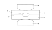
- FIG. 1 shows, as an example, a state in which two steel plates 1 and 2 are overlapped and sandwiched between welding electrodes 8 and 9.
- a point-shaped weld 4 is obtained by utilizing resistance heat generated by passing a high welding current between the welding electrodes.
- This elliptical weld 4 is called a nugget, and is the part where the two steel plates 1 and 2 melt and solidify at the contact point of the steel plates when a current is passed through the overlapping steel plates. This results in a point-shaped weld.
- TSS tensile shear test
- rust-resistant steel sheets such as zinc (Zn)-plated steel sheets (so-called “surface-treated steel sheets”) are used for parts at risk of corrosion.
- Zn-plated steel sheets so-called “surface-treated steel sheets”
- surface-treated steel sheets there is a problem that cracks may occur in the welded part during resistance spot welding of a sheet assembly in which multiple steel sheets including surface-treated steel sheets are overlapped.
- the cracks in the welded part are considered to be caused by so-called liquid metal embrittlement, in which the low-melting-point metal plating layer on the surface of the surface-treated steel sheet melts during welding, and when tensile stress due to the pressure of the welding electrode or the thermal expansion or contraction of the steel sheet is applied to the welded part, the molten low-melting-point metal penetrates the crystal grain boundaries of the base material of the surface-treated steel sheet, reducing the grain boundary strength and causing cracks (hereinafter referred to as "LME cracking").
- the location where LME cracking occurs is various, such as the surfaces of the steel sheets 1 and 2 on the sides in contact with the welding electrodes 8 and 9, as shown in Figure 7, and the surfaces of the steel sheets 1 and 2 on the sides in contact with each other.
- Patent Document 1 proposes that the composition of the steel plates in the plate assembly be set within a specific range, specifically, by weight, the composition be: C: 0.003-0.01%, Mn: 0.05-0.5%, P: 0.02% or less, sol. Al: 0.1% or less, Ti: 48 x (N/14) to 48 x (N/14) + (S/32)%, Nb: 93 x (C/12) to 0.1%, B: 0.0005-0.003%, N: 0.01% or less, Ni: 0.05% or less, with the balance being Fe and unavoidable impurities.
- Patent Document 2 proposes a spot welding method for high-strength plated steel sheet, in which spot welding is performed by setting a welding current flow time and a holding time after welding current flow so as to satisfy the following conditional expressions (A) and (B): 0.25 ⁇ (10 ⁇ t+2)/50 ⁇ WT ⁇ 0.50 ⁇ (10 ⁇ t+2)/50...(A) 300-500 ⁇ t+250 ⁇ t 2 ⁇ HT...(B)
- t is the plate thickness (mm)
- WT is the welding current flow time (ms)
- HT is the holding time after welding current flow (ms).
- Patent Document 2 also proposes performing resistance spot welding by appropriately setting the current application time and the electrode holding time after current application according to the thickness of the steel sheet, and by using a high-strength galvanized steel sheet in which the amount of alloy elements in the steel sheet is below a certain level.
- Patent Document 3 proposes a resistance spot welding method in which a current pattern is set to three or more stages, welding conditions such as current flow time and welding current are adjusted so that the appropriate current range ( ⁇ I) is 1.0 kA or more, preferably 2.0 kA or more, and a cooling time is provided between each stage.
- the appropriate current range is a current range that can stably form a nugget that is equal to or larger than the desired nugget diameter and has a molten residual thickness of 0.05 mm or more.
- Patent Document 4 proposes a technique for preventing LME cracking by removing the plating layer from the area to be welded prior to resistance spot welding.
- Patent Document 1 it is necessary to limit the amount of alloying elements in the steel plate, which creates problems such as limiting the use of steel plates that meet the required performance.
- the application of the technology in Patent Document 1 is extremely limited.
- Patent Document 2 only proposes a method for suppressing LME cracking when an excessively large welding current is set that would cause expulsion, and does not mention LME cracking in a state where expulsion does not occur.
- Patent Document 3 requires a lot of man-hours to optimize the welding conditions, and has the problem that it cannot be applied to steel plates and plate assemblies for which it is difficult to ensure an appropriate current range.
- Patent Documents 2 and 3 do not consider the effects of the welding electrode strike angle, so when considering the actual work during automobile assembly, it may be insufficient as a countermeasure.
- Patent Document 4 a step of removing the plating layer in advance is required, which increases manufacturing costs. In addition, because the plating layer is removed, it is believed that the corrosion resistance of the welded portion decreases.
- the present invention has been made in consideration of the above circumstances, and aims to provide a resistance spot welded component and a resistance spot welding method thereof that can prevent LME cracking in resistance spot welds in sheet assemblies using multiple steel sheets, particularly surface-treated steel sheets.
- LME cracks in resistance spot welds are likely to occur when excessive tensile residual stress occurs in the resistance spot weld due to construction disturbances during welding.
- LME cracks are likely to occur in areas where there is locally high tensile stress when the welding electrodes are released after the current and pressure of the resistance spot welding are applied.
- tensile stress is also likely to occur due to differences in transformation behavior during cooling.
- LME cracking occurs when tensile stress is applied to a liquid metal such as Zn in contact with a steel sheet. Therefore, the interdiffusion of Fe and Zn is promoted between the sheets (i.e., the steel sheet mating surfaces) where the strength difference between the overlapping steel sheets becomes large, and the alloying of Fe and Zn is advanced, thereby controlling the thickness of the Zn alloy layer with a certain or higher Fe concentration near the nugget. This prevents liquid Zn from being present between the sheets when the above tensile stress is applied.
- the inventors came up with the idea that this technical concept makes it possible to prevent LME cracking.
- the inventors also discovered that there are appropriate welding conditions for controlling the thickness of the Zn alloy layer with a certain or higher Fe concentration.
- the Fe-Zn alloy layer formed in a region 300 to 500 ⁇ m from the nugget end on the steel sheet mating surface in the sheet width direction has an Fe concentration of 70 to 95 mass% and a Zn concentration of 5 to 30 mass%, where t Fe-Zn ( ⁇ m) is the average thickness of the layer.
- the average thickness of the Fe-Zn alloy layer satisfies formula (1).
- Ms 1 (° C.): Ms point of the steel plate having a higher Ms point in the first plate pair
- Ms2 (°C) Ms point of the steel plate having a lower Ms point in the first plate pair
- Si High (mass%): Si concentration of the steel plate side having the largest Si content in the first plate set
- ⁇ (degrees): the inclination of the nugget, which is calculated as the angle between a straight line connecting the shoulders of the outermost steel plate side of the overlapping steel plates and a tangent to the outer peripheral edge of the nugget on the outermost steel plate side
- g Sheet (mm) the sum of the gaps between the plates of each steel plate mating surface, It is.
- a method for resistance spot welding a resistance spot welded member includes clamping two or more overlapping steel sheets between a pair of welding electrodes and applying current while applying pressure to form a nugget,
- the average current value of the main current application process is I1 (kA)
- the current application time of the main current application process is T1 (s)
- the average pressure of the welding electrode is p (kN)
- the hold time after the end of current application is T Hold (s)
- the number of the steel plates is N (sheets)
- a welding condition in the main current passing step satisfies formula (2).
- Si High is the Si concentration (mass%) of the steel plate side having the largest Si content in the first plate pair
- Ms 1 is the Ms point (°C) of the steel plate side having the higher Ms point in the first plate pair
- Ms 2 is the Ms point of the steel plate side having the lower Ms point in the first plate pair.
- a post-current application process for performing a post-heat treatment on the formed nugget after the main current application process When the average current value of the main current passing step is I1 (kA), the current passing time of the main current passing step is T1 (s), the average current value of the post-current passing step is I2 (kA), the current passing time of the post-current passing step is T2 (s), the number of current passings in the post-current passing step is Np (times), the current passing interval between the main current passing step and the post-current passing step is T3 (s), the average pressure of the welding electrodes is p (kN), the hold time after the end of current passing is THold (s), and the number of steel plates is N (sheets), 5.
- the present invention provides a resistance spot welded component that can prevent LME cracking in resistance spot welds, regardless of the composition of the steel sheets or the disturbances during welding, even in sheet combinations that use multiple steel sheets, particularly surface-treated steel sheets. It also provides a resistance spot welding method for resistance spot welded components that can produce welded joints without removing the plating layer of the Zn-plated steel sheets included in the sheet combination in advance.
- FIG. 1 is a cross-sectional view in the plate thickness direction that typically illustrates an example of resistance spot welding.
- FIG. 2 is a cross-sectional view in the sheet thickness direction that illustrates a resistance spot weld and its periphery in a resistance spot welded component according to one embodiment of the present invention, and a method for measuring t Fe-Zn .
- FIG. 3 is a cross-sectional view in the sheet thickness direction illustrating a resistance spot weld and its periphery in a resistance spot welded member according to another embodiment of the present invention, and a method for measuring t Fe-Zn .
- FIG. 1 is a cross-sectional view in the plate thickness direction that typically illustrates an example of resistance spot welding.
- FIG. 2 is a cross-sectional view in the sheet thickness direction that illustrates a resistance spot weld and its periphery in a resistance spot welded component according to one embodiment of the present invention, and a method for measuring t Fe-Zn .
- FIG. 4 is a diagram showing the relationship between t Fe-Zn , the right-hand side value of equation (1), and the evaluation of LME cracking in the resistance spot weld of the present invention.
- FIG. 5 is a cross-sectional view in the plate thickness direction for explaining a method for measuring the inclination ( ⁇ ) of the nugget, which is a processing disturbance during resistance spot welding.
- 6A and 6B are cross-sectional views in the plate thickness direction for typically explaining a method of measuring a gap (g Sheet ) between plates, which is a construction disturbance during resistance spot welding.
- FIG. 7 is a cross-sectional view in the plate thickness direction, which shows a schematic example of crack generation during conventional resistance spot welding.
- a resistance spot welded component (hereinafter referred to as a "welded component") of the present invention will be described with reference to Figures 2 and 3.
- Figures 2 and 3 show, as an example, enlarged cross-sectional views in the sheet thickness direction of a resistance spot weld in the welded component and a portion of its surroundings. The enlarged portion is the area enclosed by a rectangular frame in Figures 2 and 3.
- the present invention is a welded component having a resistance spot weld formed by resistance spot welding two or more overlapping steel sheets.
- at least one of the overlapping steel sheets is a Zn-plated steel sheet having a Zn-based plating layer on the steel sheet surface.
- the example shown in Figure 2 is a welded member 6 formed by welding two overlapping steel plates 1, 2, in which the lower steel plate 2 (hereinafter sometimes referred to as the "lower plate”) and/or the upper steel plate 1 (hereinafter sometimes referred to as the "upper plate”) are Zn-plated steel plates.
- a resistance spot weld 4 which will be described below, is formed on the steel plate mating surface 7 (i.e., the overlapping surfaces of the steel plates) where the upper plate 1 and lower plate 2 come into contact.
- FIG. 3 shows three overlapping steel plates 1, 2, and 3 welded together.
- the steel plate 2 i.e., the lower plate
- the steel plate 1 i.e., the upper plate
- the steel plate 3 hereinafter sometimes referred to as the "middle plate" placed between them are Zn-plated steel plates.
- the resistance spot welds 4 described below are formed to include the steel plate mating surfaces 7 (7a, 7b) where the lower plate 2 and the middle plate 3, and the middle plate 3 and the upper plate 1 meet.
- FIG. 4 shows the relationship between the average thickness (tFe-Zn) of the Zn alloy layer (i.e., the Fe-Zn alloy layer described below) having a certain or higher Fe concentration formed between plates in the resistance spot welded portion (hereinafter referred to as the " weld portion") of the welded member of the present invention and the right-hand side value of the formula (1) described below, and the correspondence between these and the LME crack evaluation.
- the evaluation criteria for the LME crack evaluation of the welded member welded under the plate assembly and welding conditions described in the examples described below are used.
- the unit of the thickness is ⁇ m.
- the "right-hand side value of the formula (1)" is a value calculated by "Si High ⁇ ( Ms1 - Ms2 ) 1/2 ⁇ 0.5+( ⁇ +8 ⁇ gSheet )/5".
- LME cracking occurs when tensile stress is applied to a liquid metal such as Zn in contact with a steel plate.
- a liquid metal such as Zn in contact with a steel plate.
- the above-mentioned "Zn alloy layer having a certain or higher Fe concentration” will be described.
- a Zn alloy layer is formed outside the nugget 4a and between the sheets of the overlapping steel sheets (i.e., on the steel sheet mating surface 7 side).
- the higher the Fe concentration of the Zn alloy layer the more liquid Zn is suppressed with alloying, and the more effective it is in preventing LME cracking. Therefore, in the present invention, the region where the Fe concentration is 70 to 95 mass% and the Zn concentration is 5 to 30 mass% is defined as the "Fe-Zn alloy layer", and the average thickness of the Fe-Zn alloy layer is defined as "t Fe-Zn ".
- the reason for setting the Fe concentration at 70-95 mass% and the Zn concentration at 5-30 mass% is as follows.
- the Fe concentration and Zn concentration are indicators of the degree of Fe-Zn alloying, and as alloying progresses, the Fe concentration increases and the Zn concentration decreases. If the Fe concentration is less than 70 mass% and the Zn concentration exceeds 30 mass%, the alloying will be insufficient and the effects of the present invention may not be obtained. Therefore, the Fe concentration is set to 70 mass% or more and the Zn concentration is set to 30 mass% or less.
- the Fe concentration is set to more than 95% and the Zn concentration is less than 5% in order to advance the alloying, the current application time and number of current applications will increase significantly, which may lead to a decrease in construction efficiency. Therefore, the Fe concentration is set to 95 mass% or less and the Zn concentration to 5 mass% or more.
- the degree of Fe-Zn alloying can be controlled by controlling the current pattern during welding. In particular, it is effective to maintain the temperature at a high temperature for a long period of time so that the alloying of Fe-Zn progresses while the current is flowing.
- By controlling the current pattern in this way it is possible to appropriately control the average thickness of the Fe-Zn alloy layer according to the welded plate assembly, the strength, composition, and structure of the steel plates used in the plate assembly, and disturbances during welding.
- the above-mentioned “specific region” refers to a region located 300 to 500 ⁇ m away from the nugget end E on the steel plate mating surface 7 in the plate width direction when the intersection point between the steel plate mating surface 7 and the outer peripheral edge of the nugget 4a is defined as the nugget end E.
- this region is called the “first region.”
- This first region is a region that exists inside the welding heat-affected zone 4b formed on the outer periphery of the nugget 4a, and is formed on both ends of the nugget 4a.
- the first region is illustrated only on one nugget end side, and the first region on the other nugget end side is omitted.
- the rectangular frame shown in the figures is illustrated with an appropriate length in the plate thickness direction set so as to include the Fe-Zn alloy layer 5 in the first region.
- This first region is considered to be an area where LME cracking is likely to occur.
- the reason for this is not clear, but it is thought to be as follows. Because the maximum temperature reached during welding is higher closer to the nugget, the closer to the nugget the greater the promotion of Fe-Zn alloying due to the mutual diffusion of Fe and Zn. From the perspective of Fe-Zn alloying, it is considered that LME cracking is less likely to occur in this area close to the nugget. However, the higher the maximum temperature reached, the higher the temperature when the welding electrode is released, so it is considered that liquid Zn is more likely to exist. As a result, it is considered that LME cracking is more likely to occur in the first region, which is an area located 300 to 500 ⁇ m away from the nugget end E in the sheet width direction on the steel sheet mating surface 7.
- the present invention focuses on the material properties between sheets and has found that the tFe-Zn required to suppress LME cracking changes depending on the TS difference between steel sheets, the Si content, the transformation point considering the structure fraction, and processing disturbances. Furthermore, it has been found that LME cracking can be suppressed by appropriately controlling the tFe-Zn in the first region according to the material properties between sheets.
- the weld 4 of the present invention it is important for the weld 4 of the present invention to appropriately control the thickness of the Fe-Zn alloy layer in the first region near the nugget.
- the first plate combination in which the difference in tensile strength between two steel plates that abut in the vertical direction is the greatest is referred to as the first plate combination.
- upper plate 1 and lower plate 2 form the first plate combination
- upper plate 1 and middle plate 3 form the first plate combination.
- any one of the combinations may be designated as the first plate combination.
- an Fe—Zn alloy layer having an Fe concentration of 70 to 95 mass % and a Zn concentration of 5 to 30 mass % formed in a region 300 to 500 ⁇ m in the sheet width direction from the nugget end E on the steel sheet mating surface 7 is referred to as a first region, and the average thickness of the Fe—Zn alloy layer in this first region is represented as t Fe-Zn ( ⁇ m).
- the Ms point of the steel sheet with the higher Ms point is defined as Ms 1 (° C.)
- Ms point of the steel sheet with the lower Ms point is defined as Ms 2 (° C.)
- Si concentration of the steel sheet with the highest Si content is defined as Si High (mass %).
- the inclination of the nugget which is calculated by the angle between the straight line connecting the shoulders of the outermost steel sheet side and the tangent to the outer periphery of the nugget on the outermost steel sheet side of the overlapping steel sheets, is defined as ⁇ (degrees) (see FIG. 5 ), and the sum of the gaps between the sheets at the mating surfaces 7 of the steel sheets is defined as g Sheet (mm) (see FIG. 6 ).
- ⁇ degrees
- g Sheet mm
- Ms1 and Ms2 in formula (1) refer to martensitic transformation start temperatures (Ms points), and the Ms points can be calculated by the following formula (4).
- Ms (°C) 539-423 x ⁇ [C%] x 100/(100-[ ⁇ area%]) ⁇ -30 x [Mn%] -12 x [Cr%] -18 x [Ni%] -8 x [Mo%]...
- the [element symbol %] in the above formula (4) represents the content (mass %) of each element, and elements that are not contained are set to 0.
- [ ⁇ area %] is the ferrite area ratio (%) of the steel sheet (base material) after annealing.
- the martensitic transformation start temperature (Ms point) of the steel sheet is a factor that affects the martensite fraction, i.e., the strength of the steel sheet. If the difference in Ms points is large, the strength difference between the steel sheets also increases, and the residual stress generated in the steel sheet during welding may be concentrated on one side. For this reason, the lower limit of t Fe-Zn increases with an increase in the difference in Ms points.
- the effect of the present invention is large when (Ms 1 -Ms 2 )>0, and the effect of the present invention is further increased when (Ms 1 -Ms 2 ) ⁇ 10.
- the overlapped steel sheets in the present invention are preferably different steel sheets.
- the Ms point is a factor that affects the lower limit of t Fe-Zn , but the Ms point is influenced not only by the components of the steel sheet but also by the structural fraction of the steel sheet. In particular, the influence of the ferrite phase fraction that does not dissolve C is large. Based on this, a technology for suppressing LME cracking by appropriately controlling t Fe-Zn by using the Ms point considering the ferrite phase fraction has been found.
- the inclination ( ⁇ ) of the nugget is considered to be caused by the impact angle during welding.
- the moment generated by the impact angle during pressure application causes tensile stress in a part of the steel plate.
- the lower limit of tFe -Zn increases as the inclination of the nugget increases.
- the average thickness (t Fe-Zn ) of the Fe-Zn alloy layer in the first region on the steel sheet mating surface side in the first sheet pair satisfies formula (1).
- the upper limit of formula (1) is not particularly specified.
- the upper limit of tFe -Zn in formula (1) is preferably 20 ( ⁇ m) or less, more preferably 15 ( ⁇ m) or less, and even more preferably 14.0 ( ⁇ m) or less.
- the first regions that satisfy the formula (1) are formed on both end sides of the nugget.
- the first region formed on either side of the nugget end is the measurement target.
- the first region formed on the opposite side to the inclined side is the measurement target.
- the nugget 4a is inclined in the direction shown in FIG. 5 (that is, when the nugget 4a is inclined so that the left side of the paper surface is lowered with respect to the steel plate mating surface 7)
- the first region on the right side of the nugget is the measurement target.
- the first region formed on the steel plate mating surface where the difference in TS between the abutting steel plates is the largest is the measurement target.
- the above-mentioned Si High concentration, Ms 1 , Ms 2 , ⁇ , g Sheet and t Fe-Zn can be measured by the method described in the examples below.
- the overlapping steel sheets i.e., the sheet set
- the overlapping steel sheets may be all Zn-plated steel sheets, or may be a combination of a Zn-plated steel sheet and a steel sheet not having a metal plating layer (so-called "cold-rolled steel sheet"). In either case, the effect of the present invention can be obtained.
- Zn-plated steel sheet refers to a steel sheet having a Zn-based plating layer, such as zinc plating represented by electrolytic galvanizing (EG), hot-dip galvanizing (GI) and alloyed hot-dip galvanizing (GA), or zinc alloy plating containing elements such as aluminum and magnesium in addition to zinc, on the surface of the base steel sheet, which is the base material.
- Zn-based plating layer such as zinc plating represented by electrolytic galvanizing (EG), hot-dip galvanizing (GI) and alloyed hot-dip galvanizing (GA), or zinc alloy plating containing elements such as aluminum and magnesium in addition to zinc, on the surface of the base steel sheet, which is the base material.
- the composition in the plating layer is not particularly limited, in order to increase tFe -Zn , the Fe concentration in the plating layer is preferably 5 mass% or more. From the viewpoint of preventing a decrease in the powdering property of the steel sheet, the Fe concentration in the plating layer is preferably 30 mass% or less.
- the steel plates used in the plate assembly can have the following configurations as necessary.
- Si content of steel sheet it is preferable that at least one steel plate having a Si content of 0.5 mass % or more is included among the plurality of steel plates used in the plate assembly.
- Si is less than 0.5% by mass
- LME cracking may not occur regardless of disturbances or other welding conditions. The reason for this is unclear, but it is thought to be as follows. It is thought that Si has the effect of expanding the liquid-solid coexistence region in the phase diagram, and the addition of Si is thought to delay the solidification of Zn during the cooling process during welding. This prolongs the state in which liquid Zn exists, and it is thought that LME cracking is more likely to occur due to interaction with local tensile stress that occurs during holding or when the electrode is opened. If the Si content is low, interaction between liquid Zn and tensile stress is unlikely to occur, and depending on the welding conditions, LME cracking may not occur even if a method other than the welding conditions of the present invention is used.
- LME cracking is considered when the Si content is 0.5% by mass or more. Therefore, it is preferable that at least one of the steel plates used in the plate assembly is within the range of the steel plate composition described below and has a Si content of 0.5% by mass or more.
- the welding method of the present invention promotes the alloying of Zn present between all of the overlapping steel plates, so the Si content of all of the steel plates used in the plate assembly may be 0.5 mass% or more.
- ⁇ TS Max the TS difference
- ⁇ TS Max the TS difference
- ⁇ TS Max is 200 MPa or more in the sheet assembly.
- tensile stress due to differences in transformation behavior during cooling is likely to occur, and it is considered that LME cracking is likely to occur.
- the LME cracking suppression effect by promoting Fe-Zn alloying according to the present invention can be more effectively obtained, and the degree of freedom in the structural design of automobiles can be improved.
- ⁇ TS Max is preferably 2000 MPa or less.
- ⁇ TS Max is more preferably 250 MPa or more, and even more preferably 350 MPa or more.
- ⁇ TS Max is more preferably 1800 MPa or less, and even more preferably 1700 MPa or less.
- At least one of the above-mentioned overlapping steel plates has a tensile strength of 980 MPa or more.
- the tensile strength of the steel plate is preferably 3000 MPa or less.
- composition of the high-strength steel plate used in the present invention is not particularly limited as long as it can provide the above-mentioned weld configuration. From the viewpoint of applying the present invention to structural parts of automobiles, the composition of the steel plate is preferably as shown below. In the following description, the "%" designation of the composition means “mass %" unless otherwise specified.
- C 0.01-0.40% C is an element that contributes to increasing the strength of the steel plate. Therefore, the C content is preferably 0.01% or more. The C content is more preferably 0.02% or more. On the other hand, if C is added in excess, the welded portion becomes excessively hard, causing a decrease in the toughness of the welded portion. Therefore, the C content is preferably 0.40% or less. The C content is more preferably 0.38% or less.
- Si 0.02-2.50% Si is an element effective in improving the strength and elongation of steel sheet. Therefore, the Si content is preferably 0.02% or more. The Si content is more preferably 0.10% or more. On the other hand, excessive addition of Si causes a decrease in LME resistance and galvanic properties. Therefore, the Si content is preferably 2.50% or less. The Si content is more preferably 2.00% or less.
- Mn 1.0-5.0% Mn is an element that contributes to increasing the strength of steel plate. Therefore, the Mn content is preferably 1.0% or more. More preferably, the Mn content is 1.2% or more. On the other hand, excessive addition of Mn promotes solidification segregation of alloy elements in the nugget, causing a decrease in the toughness of the weld. Therefore, the Mn content is preferably 5.0% or less. More preferably, the Mn content is less than 3.5%.
- the P content is preferably 0.050% or less.
- the P content is more preferably 0.020% or less.
- the P content is preferably 0.005% or more.
- the S content is preferably 0.100% or less.
- the S content is more preferably 0.010% or less, and further preferably 0.005% or less.
- the S content is preferably 0.001% or more.
- Al 0.010-1.000%
- Al is an element necessary for deoxidation, and in order to obtain this effect, it is desirable to contain 0.010% or more of Al.
- the upper limit of the Al content is preferably set to 1.000%.
- the Al content is more preferably 0.800% or less.
- N 0.0100% or less Since N forms coarse nitrides, which reduces local deformability and reduces the ductility of the steel sheet, it is desirable to suppress the content. This tendency becomes more pronounced when the N content exceeds 0.0100%, so it is preferable to set the N content to 0.0100% or less.
- the N content is more preferably 0.0075% or less. There is no particular lower limit for the N content, but extremely low N content increases steelmaking costs. Therefore, it is preferable to set the N content to 0.0001% or more.
- the above is the basic composition, with the remainder being Fe and unavoidable impurities.
- unavoidable impurities include Co, Sn, and Zn, and the allowable ranges for their contents are Co: 0.05% or less, Sn: 0.01% or less, and Zn: 0.01% or less.
- each of the components Ti, B, Nb, Cr, Ni, Mo, Cu, Sb, V, Ca, and REM may be contained as necessary, so these components may be 0%.
- Ti 0.1% or less Ti is effective for precipitation hardening of steel sheet by forming fine carbonitrides. When Ti is contained to obtain this effect, it is preferable to contain Ti at 0.005% or more. On the other hand, if a large amount of Ti is added, elongation is significantly reduced, so the Ti content is preferably 0.1% or less. The Ti content is more preferably 0.065% or less.
- B 0.010% or less
- B is an element that improves the hardenability of steel sheets and contributes to high strength.
- B is preferable to contain B at 0.0002% or more.
- the content of B is preferably 0.010% or less.
- the B content is preferably 0.008% or less.
- Nb 0.1% or less Nb is effective for precipitation hardening of steel sheets by forming fine carbonitrides. When Nb is contained to obtain this effect, it is preferable to contain 0.005% or more of Nb. On the other hand, if a large amount of Nb is added, not only does the elongation decrease significantly, but also slab cracks occur after continuous casting, so the Nb content is preferably 0.1% or less. The Nb content is more preferably 0.07% or less, and even more preferably 0.055% or less.
- Cr 1.0% or less Cr is an element that easily generates martensite in resistance welds, and therefore contributes to increasing the shear tensile strength. When Cr is contained to exert this effect, it is preferable to contain 0.05% or more of Cr. On the other hand, if Cr is contained in excess of 1.0%, surface defects are likely to occur, so the Cr content is preferably 1.0% or less. The Cr content is preferably 0.8% or less.
- Ni 0.50% or less
- Ni is an element that contributes to high strength by solid solution strengthening and transformation strengthening of steel sheets. When Ni is contained to exert these effects, it is preferable to contain Ni at 0.005% or more.
- Ni when Ni is added simultaneously with Cu, it is effective when Cu is added because it has the effect of suppressing surface defects caused by Cu. On the other hand, even if Ni is contained in an amount exceeding 0.50%, the effect is saturated, so it is preferable to set the Ni content to 0.50% or less.
- Mo 0.5% or less
- Mo is an element that easily generates martensite in resistance welds, and therefore contributes to increasing the shear tensile strength.
- Mo is contained to exert these effects, it is desirable to contain Mo at 0.01% or more.
- the Mo content is preferably 0.02% or more.
- the Mo content is preferably 0.5% or less.
- the Mo content is more preferably 0.42% or less.
- Cu 1.0% or less
- Cu is an element that contributes to solid solution strengthening of steel sheets. When Cu is contained to exert this effect, it is preferable to contain Cu at 0.005% or more. On the other hand, even if Cu is contained at more than 1.0%, the effect is saturated and surface defects caused by Cu are likely to occur. Therefore, it is preferable that the Cu content is 1.0% or less.
- Sb 0.20% or less
- Sb has the effect of suppressing the formation of a decarburized layer in the surface layer of the steel sheet, and therefore can suppress the reduction of martensite on the steel sheet surface.
- the Sb content is preferably 0.001% or more.
- the Sb content is preferably 0.20% or less.
- V 0.05% or less V forms fine carbonitrides, which is effective in precipitation hardening of steel sheets.
- V content is 0.005% or more.
- the strength increase effect is small when it exceeds 0.05%, and it also leads to an increase in alloy costs. Therefore, it is preferable that the V content is 0.05% or less.
- Ca and REM are elements that contribute to improving delayed fracture resistance by making the shape of sulfides spherical, and can be added as necessary. When contained to exert these effects, it is preferable to contain Ca and REM at 0.0005% or more. On the other hand, even if Ca and REM are contained at more than 0.05%, the effect is saturated, so it is preferable to set the content of Ca and REM at 0.05% or less.
- Resistance spot welding method An embodiment of a resistance spot welding method for producing a welded component of the present invention will be described.
- the welded member of the present invention is manufactured by resistance spot welding, in which a sheet assembly made of multiple overlapping steel sheets, including at least one of the above-mentioned Zn-plated steel sheets, is clamped between a pair of welding electrodes and joined by passing electricity through the sheets while applying pressure.
- a sheet assembly may also be made using a steel sheet having a Zn-based plating layer (GI steel sheet, GA steel sheet, EG steel sheet) and a steel sheet having no plating layer (cold-rolled steel sheet). In this case, the sheets are overlapped so that the surface having the Zn-based plating layer is in contact with the cold-rolled steel sheet.
- GI steel sheet, GA steel sheet, EG steel sheet a steel sheet having no plating layer
- a welding device that can be used with the resistance spot welding method of the present invention is equipped with a pair of upper and lower welding electrodes, and can arbitrarily control the pressure and welding current during welding.
- pressure mechanisms include air cylinders and servo motors, and examples of types include stationary types and robot guns.
- types include stationary types and robot guns.
- the type of the tip of the welding electrode include DR type (dome radius type), R diameter (radius type), D type (dome type), etc. described in JIS C 9304:1999.
- the tip diameter of the welding electrode is, for example, 4 mm to 16 mm.
- the radius of curvature of the tip of the welding electrode is, for example, 10 mm to 400 mm.
- the present invention can be applied to both DC and AC welding power sources. In the case of AC, "current" means "effective current.”
- the current flow pattern during welding is appropriately controlled to promote the mutual diffusion of Fe and Zn.
- the current pattern during welding can be controlled by only the main current process, or the current pattern during welding can be controlled by both the main current process and the post-current process.
- the main current process and the post-current process it becomes possible to maintain the high temperature range at which the alloying of Fe-Zn progresses more stably for a long period of time compared to current passing only through the main current process.
- the current application pattern of the present invention may include only the main current application step, or may include both the main current application step and the post-current application step.
- the case including only the main current application step is referred to as a "first current application pattern", and one embodiment of the first current application pattern will be described below.
- the average current value of the main current flow process is I1 (kA)
- the current flow time of the main current flow process is T1 (s)
- the average pressure of the welding electrode during current flow is p (kN)
- the hold time after the end of current flow is THold (s)
- the number of steel plates is N (sheets).
- Si High is the Si concentration (mass%) of the steel plate side having the largest Si content in the first plate pair
- Ms 1 is the Ms point (°C) of the steel plate side having the higher Ms point in the first plate pair
- Ms 2 is the Ms point of the steel plate side having the lower Ms point in the first plate pair.
- the welding conditions in this current flow process are controlled so as to satisfy the relationship in formula (2).
- the left side value of formula (2) is preferably equal to or greater than the right side value of formula (2) times 1.05.
- the "right side value of formula (2)" above is the value of "(Si High ⁇ (Ms 1 -Ms 2 ) 1/2 ⁇ p ⁇ 30/N)."
- the upper limit of formula (2) is not particularly limited. In order to prevent significant splashing due to excessive heat input and excessive increase in takt time in the automobile manufacturing process, in addition to controlling according to formula (2), it is preferable that I1 is 15.0 kA or less and T1 is 2.0 s or less. More preferably, I1 is 4.0 kA or more and T1 is 0.2 s or more.
- the average current value of the main current process is I1 (kA)
- the current duration of the main current process is T1 (s)
- the average current value of the post-current process is I2 (kA)
- the current duration of the post-current process is T2 (s)
- the number of currents in the post-current process is Np (times).
- the current interval (no current duration) between the main current process and the post-current process is T3 (s)
- the average pressure of the welding electrode during current is p (kN).
- the hold time after the end of current is THold (s), and the number of steel plates is N (sheets).
- formula (3) is used instead of formula (2) used in the first current flow pattern described above.
- the welding conditions in the main current process and the post current process are controlled so as to satisfy the relationship in formula (3).
- the left side value of formula (3) is preferably equal to or greater than the right side value of formula (3) times 1.05.
- the "right side value of formula (3)" above is the value of "(Si High ⁇ (Ms 1 -Ms 2 ) 1/2 ⁇ p ⁇ 30/N)."
- the upper limit of formula (3) is not particularly limited. In order to prevent significant splashing due to excessive heat input and excessive increase in tact time in automobile manufacturing processes, in addition to controlling the welding conditions of the main current process and the post current process to formula (3), it is preferable that I1 and I2 are each 15.0 kA or less, and T1 and T2 are a total of 2.0 s or less. More preferably, I1 and I2 are each 3.0 kA or more, and T1 and T2 are a total of 0.2 s or more.
- the electrode is held for a predetermined time (hold time).
- This hold time is 0.02 to 1.00 seconds.
- the hold time is preferably 0.05 seconds or more, and is preferably 0.50 seconds or less.
- a non-current step in which current is stopped may be included between the main current step and the post-current step.
- the non-current step it is preferable to repeat the non-current step and the post-current step after the main current step. This is because the effect of the present invention can be obtained more effectively.
- T 3 (s) indicates the non-energization time of the non-energization step. Therefore, when there is no non-energization step, T 3 (s) in the above formula (3) is set to 0.
- N P (times) indicates the number of repetitions.
- the post-current passing step in order to promote the mutual diffusion of Fe and Zn while suppressing the expulsion due to the remelting of the nugget and to increase tFe -Zn , it is effective to maintain the vicinity of the nugget in a certain temperature range after the completion of the main current passing step. Therefore, in the present invention, it is preferable to provide a no-current passing step as a current passing interval between the main current passing step and the post-current passing step.
- the post-current process When the post-current process is performed at a constant current value, if the current value of the post-current process is large, the temperature near the nugget will gradually rise, and conversely, if the current value of the post-current process is small, the temperature near the nugget will gradually fall. Even in such a state, it is believed that the desired effect can be obtained by appropriately setting the current value of the post-current process, but the amount of work required to derive the optimal conditions may increase.
- maintaining a constant temperature range not only requires strict condition control, but also becomes even more difficult when disturbances in the welding process occur, as described below.
- by repeating the no-energization process and post-energization process it is possible to maintain the temperature near the nugget within a relatively constant range, even if the total energization time in the post-energization process increases.
- the second current pattern of the present invention may have a de-energization step after the main current step, and the de-energization step and the post-current step may be repeated.
- This makes it possible to easily maintain the vicinity of the nugget within a constant temperature range, and also widens the appropriate current range in the post-current step, which is thought to improve robustness against welding disturbances.
- the de-energization time is too short, there is a concern that the nugget will re-melt and cause increased spattering, while if the de-energization time is too long, the desired heat treatment effect may not be obtained. Therefore, the time for the de-energization step is preferably 0.01 s or more, and 0.20 s or less.
- the de-energization process and post-energization process need to be performed at least once, and if the de-energization process and post-energization process are repeated, the number of repetitions is more preferably two or more, and even more preferably three or more. There is no particular upper limit to the number of repetitions, but generally there is an upper limit to the number of repetitions that can be set with welding equipment, and setting a repetition number exceeding the upper limit requires modification of the welding equipment. Therefore, because of the increased equipment costs in the automobile manufacturing process, the number of repetitions is preferably 20 or less, and even more preferably 10 or less.
- the present invention may have the following welding conditions.
- At least one welding point satisfies one or more of the following conditions (a) to (d) immediately before applying pressure with the welding electrode. This makes it possible to more effectively obtain the effects of the present invention.
- the impact angle between the welding electrode and two or more overlapping steel sheets is 0.2 degrees or more.
- the impact angle means the angle at which the electrode is inclined with respect to the steel sheets, that is, the angle between the electrode pressure direction and the thickness direction of the steel sheets. If the impact angle is large, bending stress is applied to the weld, causing large localized compressive plastic deformation, which increases the tensile stress after cooling.
- the nugget that is formed is also tilted, so when determining the strike angle from the cross section after welding, the inclination of the nugget is used as the strike angle.
- this "strike angle” is one of the construction disturbances when welding, but for the reasons mentioned above, the "slope of the nugget" in the component obtained after welding can be used instead as this "strike angle.”
- the " ⁇ ” indicating the "inclination of the nugget” is obtained by the method shown in FIG. 5.
- a straight line connecting the outermost parts (i.e., the boundary part where deformation due to pressure of the welding electrode is not observed) of the left and right shoulder parts on the upper plate 1 side (i.e., the steel plate side of the outermost layer of the plate assembly) is used as a reference, and the angle between the reference line and two perpendicular lines drawn from positions 500 ⁇ m away on the left and right from the center of this reference line (hereinafter referred to as the "reference line") and the lines passing through the intersections of the outermost edge of the nugget (i.e., the outer peripheral edge of the nugget 4a) is ⁇ .
- the above "two perpendicular lines” are lines parallel to the midline drawn from the center position of the reference line.
- the effect of the present invention can be effectively obtained when the impact angle is 0.2 degrees or more. If the impact angle is too large, the nugget formation becomes unstable and causes splashing, so it is preferable that the impact angle be 10.0 degrees or less.
- the impact angle is more preferably 1.0 degrees or more, and even more preferably 8.0 degrees or less.
- Misalignment means a state in which the central axes of the pair of welding electrodes are not aligned. As with the impact angle described above, if the misalignment is large, bending stress is applied to the welded portion, making LME cracking more likely to occur. When the misalignment amount is 0.1 mm or more, the effect of the present invention can be effectively obtained. If the misalignment amount is excessive, the nugget formation becomes unstable and causes expulsion, so it is preferable that the misalignment amount is 5.0 mm or less. The misalignment amount is more preferably 0.2 mm or more, and even more preferably 3.0 mm or less.
- the "gap between the steel plates” described in (c) above is one of the construction disturbances during welding, but for the reasons described above, the "gap between the steel plates after welding" in the member obtained after welding may be substituted for this "gap between the steel plates".
- the " gSheet " indicating the "gap between steel sheets after welding” is determined by the method shown in Figures 6(A) and 6(B).
- Figure 6(A) in the case of continuous welding, the difference between the maximum thickness of the steel sheets 1, 2 between two adjacent nuggets 4a and the total sheet thickness of the overlapped steel sheets 1, 2 is determined, and this is taken as gSheet .
- Figure 6(B) the difference between the maximum thickness of the steel sheets 1, 2 between the nugget 4a and the end of the sheet set and the total sheet thickness of the overlapped steel sheets 1, 2 is determined, and this is taken as gSheet .
- the effects of the present invention can be effectively obtained when the gap is 0.5 mm or more. If the gap is too large, the nugget formation becomes unstable and may cause splashing, so it is preferable to set the gap to 4.0 mm or less.
- the gap is more preferably 1.0 mm or more, and even more preferably 3.0 mm or less.
- the pressure conditions in each step are not particularly limited. From the perspective of automotive applications, it is preferable to adjust the pressure conditions to a range of 2.0 to 8.0 kN.
- the steel plates shown in Table 1 were used to form a plate assembly, which was then welded under the welding conditions shown in Tables 2 and 3 to produce a welded joint (welded member).
- the plate assembly was overlapped with the bottom plate first, followed by the top plate, or the bottom plate, middle plate, and top plate, as shown in Table 2.
- the welding equipment used was a single-phase AC (50 Hz) resistance welding machine with a servo motor pressure system attached to a welding gun.
- the pair of electrode tips used were chromium copper DR-type electrodes with a tip curvature radius R of 40 mm and a tip diameter of 6 mm.
- GI refers to a steel sheet having a hot-dip galvanized layer (hot-dip galvanized steel sheet)
- GA refers to a steel sheet having a galvannealed hot-dip galvanized layer (galvannealed hot-dip galvanized steel sheet)
- EG refers to a steel sheet having an electrogalvanized layer (electrogalvanized steel sheet)
- - refers to a steel sheet without a plating layer (cold-rolled steel sheet).
- composition of the components shown in Table 1 was measured using inductively coupled plasma (ICP) optical emission spectroscopy.
- ICP inductively coupled plasma
- the "Tensile strength” column in Table 1 shows the tensile strength (TS) (unit: MPa) measured by taking JIS No. 5 tensile test pieces from each steel plate in the rolling direction and conducting tensile tests in accordance with JIS Z 2241.
- the "structure fraction" column in Table 1 shows the area fraction (%) of ferrite ( ⁇ ) in the area observed by scanning electron microscope (SEM) for each steel plate.
- the obtained ferrite area fraction was used to calculate the martensitic transformation start temperature (Ms) for each steel plate from the above-mentioned formula, and the calculated Ms is shown in the "transformation point" column in Table 1.
- the area fraction is measured as follows. The cross section of the steel plate cut parallel to the rolling direction is polished, then corroded with 3% by volume of nital, and three fields of view are photographed at 1/4 of the plate thickness using an SEM at a magnification of 1500 times. The area fraction is calculated from the obtained image data using Image-Pro manufactured by Media Cybernetics. The average value of the area fractions of the three fields of view is defined as the area fraction of the present invention. In the image data, ferrite can be distinguished as black.
- the 10 kg-HV hardness (average of the median 3 points/5 points) at the 1/4 position of the plate thickness was multiplied by 0.32 to determine TS, and the plate combination (i.e., the first plate combination) in which the strength between the steel plates was maximum ( ⁇ TS MAX ) was identified.
- the values of Ms 1 and Ms 2 in this first plate combination were calculated using the above formula (4) and are shown in Table 2.
- N P shown in the "Welding Conditions” column in Table 3 indicates the number of times the no-current process and the post-current process are repeated. For example, in the case of “main current process only”, N P is 0 (times), in the case of “main current process-no-current process-post-current process”, N P is 1 (times), and in the case of "main current process-no-current process (1)-post-current process (1)-no-current process (2)-post-current process (2)", N P is 2 (times).
- the average thickness (t Fe-Zn ) of the Fe-Zn alloy layer in the Zn alloy layer was measured and the LME cracking of the welded portion was evaluated by the methods described below.
- the method for measuring t Fe-Zn is not particularly limited as long as it can quantitatively measure the Fe concentration.
- it can be measured by EPMA or SEM-EDS.
- SEM-EDS was measured by SEM-EDS.
- the conditions for SEM-EDS were as follows. EDS conditions: A Ka radiation source is used as the radiation source of the X-rays to be irradiated, magnification: 1500 times or more, acceleration voltage: 15 kV, scan time: 1 min or more (excluding the gaps). Specifically, the thickness of the gaps is subtracted from the thickness including the gaps. If the thickness of the gaps is difficult to determine, the thickness is measured from the nearest part without gaps.
- the observation area was a region (i.e., the first region) 300 to 500 ⁇ m away from the end E of the nugget 4a in the sheet width direction on the steel sheet mating surface 7 where the Fe-Zn alloy layer was formed in the weld.
- the start point of the observation position is a position 300 ⁇ m away from the nugget end E in the sheet width direction (i.e., one side of the first region perpendicular to the steel sheet mating surface 7 located on the left side of the paper in each figure), and the end point of the observation position is a position 500 ⁇ m away from the nugget end E in the sheet width direction (i.e., one side of the first region perpendicular to the steel sheet mating surface 7 located on the right side of the paper in each figure).
- the region from the start point to the end point is observed at equal intervals, and the region in which the Fe concentration is 70 to 95 mass% and the Zn concentration is 5 to 30 mass% among the Zn-enriched parts between the sheets in each field of view is identified as an Fe-Zn alloy layer, and the thickness of the Fe-Zn alloy layer is measured.
- the average value of the values excluding the maximum and minimum values of the thicknesses of the obtained Fe-Zn alloy layers was taken as the average thickness (t Fe-Zn ) of the Fe-Zn alloy layer.
- observing at equal intervals refers to observing at least 10 visual fields at equal intervals.
- the visual fields may be set appropriately within the range of, for example, 11 to 100. Since accurate values may not be obtained if the measurement interval is less than 10, the visual field was set to 10 in this example.
- the following analysis method was used to measure the "Fe concentration,” “Zn concentration,” and "Fe-Zn alloy layer thickness" above.
- Concentration measurements can be performed, for example, by line analysis or point analysis. When performing concentration measurements using these analyses, concentration measurements are performed at least at five or more lines per field of view, and the Fe concentration and Zn concentration are recorded for each measurement line. In the case of point analysis, it is preferable to perform measurements at a pitch of 1 ⁇ m or less per location.
- the thickness of the Fe--Zn alloy layer in the first region was measured as follows. First, the first region to be measured was specified as described above. Next, the thickness of the Fe—Zn alloy layer in the first region to be measured was measured. The thickness was measured at the location where the concentration measurement was performed using the above-mentioned measurement method, and the Fe—Zn alloy layer thickness in each line was measured. The average value of the Fe—Zn alloy layer thicknesses in all lines measured within the field of view, excluding the maximum and minimum values, was calculated.
- ⁇ Evaluation criteria> A rating: 0/5 (i.e., 0 out of 5 pieces were found to be cracked) B rating: 1/5 (i.e., one out of five pieces was found to be cracked) C rating: 2/5 to 4/5 (i.e., 2 to 4 of the 5 bodies were found to be cracked)
Landscapes
- Engineering & Computer Science (AREA)
- Mechanical Engineering (AREA)
- Chemical & Material Sciences (AREA)
- Materials Engineering (AREA)
- Metallurgy (AREA)
- Organic Chemistry (AREA)
- Resistance Welding (AREA)
Priority Applications (1)
| Application Number | Priority Date | Filing Date | Title |
|---|---|---|---|
| JP2025540269A JP7831700B2 (ja) | 2023-12-08 | 2024-12-02 | 抵抗スポット溶接部材およびその抵抗スポット溶接方法 |
Applications Claiming Priority (2)
| Application Number | Priority Date | Filing Date | Title |
|---|---|---|---|
| JP2023-207929 | 2023-12-08 | ||
| JP2023207929 | 2023-12-08 |
Publications (1)
| Publication Number | Publication Date |
|---|---|
| WO2025121278A1 true WO2025121278A1 (ja) | 2025-06-12 |
Family
ID=95979915
Family Applications (1)
| Application Number | Title | Priority Date | Filing Date |
|---|---|---|---|
| PCT/JP2024/042494 Pending WO2025121278A1 (ja) | 2023-12-08 | 2024-12-02 | 抵抗スポット溶接部材およびその抵抗スポット溶接方法 |
Country Status (2)
| Country | Link |
|---|---|
| JP (1) | JP7831700B2 (https=) |
| WO (1) | WO2025121278A1 (https=) |
Citations (4)
| Publication number | Priority date | Publication date | Assignee | Title |
|---|---|---|---|---|
| WO2017104647A1 (ja) * | 2015-12-16 | 2017-06-22 | Jfeスチール株式会社 | 抵抗スポット溶接方法および溶接部材の製造方法 |
| WO2018159764A1 (ja) * | 2017-03-01 | 2018-09-07 | Jfeスチール株式会社 | 抵抗スポット溶接方法 |
| JP2020082102A (ja) * | 2018-11-19 | 2020-06-04 | 株式会社神戸製鋼所 | 接合構造体及び接合構造体の製造方法 |
| WO2023080076A1 (ja) * | 2021-11-02 | 2023-05-11 | Jfeスチール株式会社 | 抵抗スポット溶接部材およびその抵抗スポット溶接方法 |
-
2024
- 2024-12-02 WO PCT/JP2024/042494 patent/WO2025121278A1/ja active Pending
- 2024-12-02 JP JP2025540269A patent/JP7831700B2/ja active Active
Patent Citations (4)
| Publication number | Priority date | Publication date | Assignee | Title |
|---|---|---|---|---|
| WO2017104647A1 (ja) * | 2015-12-16 | 2017-06-22 | Jfeスチール株式会社 | 抵抗スポット溶接方法および溶接部材の製造方法 |
| WO2018159764A1 (ja) * | 2017-03-01 | 2018-09-07 | Jfeスチール株式会社 | 抵抗スポット溶接方法 |
| JP2020082102A (ja) * | 2018-11-19 | 2020-06-04 | 株式会社神戸製鋼所 | 接合構造体及び接合構造体の製造方法 |
| WO2023080076A1 (ja) * | 2021-11-02 | 2023-05-11 | Jfeスチール株式会社 | 抵抗スポット溶接部材およびその抵抗スポット溶接方法 |
Also Published As
| Publication number | Publication date |
|---|---|
| JP7831700B2 (ja) | 2026-03-17 |
| JPWO2025121278A1 (https=) | 2025-06-12 |
Similar Documents
| Publication | Publication Date | Title |
|---|---|---|
| KR101805284B1 (ko) | 스폿 용접 조인트 및 스폿 용접 방법 | |
| KR102945885B1 (ko) | 저항 스폿 용접 부재 및 그 저항 스폿 용접 방법 | |
| KR20210089764A (ko) | 스폿 용접 부재 | |
| JP6780386B2 (ja) | スポット溶接方法 | |
| JP7477061B1 (ja) | 溶接部材およびその製造方法 | |
| JP6384603B2 (ja) | スポット溶接方法 | |
| KR102943500B1 (ko) | 저항 스폿 용접 부재 및 그 저항 스폿 용접 방법 | |
| JP2016032834A (ja) | 重ね溶接部材、重ね溶接部材の重ね抵抗シーム溶接方法及び重ね溶接部を備える自動車用重ね溶接部材 | |
| US20230105155A1 (en) | Welded member having excellent fatigue strength of welded portion and method for manufacturing same | |
| CN119604382A (zh) | 点焊接头的制造方法及点焊接头 | |
| JP7485242B1 (ja) | 溶接部材およびその製造方法 | |
| JP7831700B2 (ja) | 抵抗スポット溶接部材およびその抵抗スポット溶接方法 | |
| JP7831701B2 (ja) | 抵抗スポット溶接部材およびその抵抗スポット溶接方法 | |
| KR20240026245A (ko) | 저항 스폿 용접 이음 및 그 저항 스폿 용접 방법 | |
| JP7477059B1 (ja) | 溶接部材およびその製造方法 | |
| JP7435935B1 (ja) | 溶接部材およびその製造方法 | |
| JP7648019B2 (ja) | 抵抗スポット溶接方法、並びに溶接部材の製造方法 | |
| KR102948515B1 (ko) | 저항 스폿 용접 방법 | |
| JP7522977B2 (ja) | 抵抗スポット溶接方法 | |
| JP7347716B1 (ja) | 抵抗スポット溶接継手および抵抗スポット溶接方法 | |
| WO2024063010A1 (ja) | 溶接部材およびその製造方法 | |
| JP7827230B1 (ja) | 抵抗スポット溶接継手の製造方法及びめっき層の融点予測方法 | |
| JP7476957B2 (ja) | 抵抗スポット溶接方法 | |
| KR20250105427A (ko) | 저항 스폿 용접 이음매 및 그 저항 스폿 용접 방법 |
Legal Events
| Date | Code | Title | Description |
|---|---|---|---|
| ENP | Entry into the national phase |
Ref document number: 2025540269 Country of ref document: JP Kind code of ref document: A |
|
| WWE | Wipo information: entry into national phase |
Ref document number: 2025540269 Country of ref document: JP |
|
| 121 | Ep: the epo has been informed by wipo that ep was designated in this application |
Ref document number: 24900572 Country of ref document: EP Kind code of ref document: A1 |