WO2025120844A1 - 排気マニホールド - Google Patents
排気マニホールド Download PDFInfo
- Publication number
- WO2025120844A1 WO2025120844A1 PCT/JP2023/044016 JP2023044016W WO2025120844A1 WO 2025120844 A1 WO2025120844 A1 WO 2025120844A1 JP 2023044016 W JP2023044016 W JP 2023044016W WO 2025120844 A1 WO2025120844 A1 WO 2025120844A1
- Authority
- WO
- WIPO (PCT)
- Prior art keywords
- pipe
- exhaust manifold
- inner pipe
- flange portion
- outer pipe
- Prior art date
- Legal status (The legal status is an assumption and is not a legal conclusion. Google has not performed a legal analysis and makes no representation as to the accuracy of the status listed.)
- Pending
Links
Images




Classifications
-
- F—MECHANICAL ENGINEERING; LIGHTING; HEATING; WEAPONS; BLASTING
- F01—MACHINES OR ENGINES IN GENERAL; ENGINE PLANTS IN GENERAL; STEAM ENGINES
- F01N—GAS-FLOW SILENCERS OR EXHAUST APPARATUS FOR MACHINES OR ENGINES IN GENERAL; GAS-FLOW SILENCERS OR EXHAUST APPARATUS FOR INTERNAL-COMBUSTION ENGINES
- F01N13/00—Exhaust or silencing apparatus characterised by constructional features
- F01N13/08—Other arrangements or adaptations of exhaust conduits
- F01N13/10—Other arrangements or adaptations of exhaust conduits of exhaust manifolds
Definitions
- the present invention relates to an exhaust manifold.
- Patent Document 1 describes a double exhaust pipe for an engine that has an outer pipe and an inner pipe, and that is joined and welded to a flange on the inner circumferential surface of the outer pipe and the inner pipe downstream in the flow direction of exhaust gas.
- the present invention was made in consideration of these problems, and its purpose is to provide an exhaust manifold that can further improve durability against thermal expansion occurring in the inner pipe and against forces transmitted from downstream devices.
- the exhaust manifold of the present invention is an exhaust manifold comprising a plurality of branch pipe sections connected to each cylinder of an internal combustion engine and a collecting pipe section where the branch pipe sections join together, comprising an inner pipe through which exhaust gas from the internal combustion engine flows, an outer pipe that covers the inner pipe from the outside, and a flange section that supports the inner pipe and the outer pipe in the collecting pipe section and has an opening that serves as an outlet for exhaust gas flowing through the inner pipe, the inner pipe is inserted into the inner peripheral surface of the opening in the flange section, and the outer pipe is abutted against the end face of the flange section outside the inner pipe.
- the exhaust manifold of the present invention can further improve durability against thermal expansion occurring in the inner pipe and against forces transmitted from downstream devices.
- FIG. 1 is a plan view showing an outline of an engine to which an exhaust manifold according to an embodiment is applied and its intake and exhaust system.
- 1 is a side view showing an outline of an engine to which an exhaust manifold according to an embodiment is applied and its intake and exhaust system.
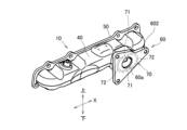
- FIG. 2 is a perspective view of the exhaust manifold as viewed from the downstream side and above.
- FIG. 2 is a perspective view of the exhaust manifold as viewed from the downstream side and above.
- FIG. 2 is a perspective view of the exhaust manifold as viewed from the downstream side and above.
- FIG. 2 is a perspective view of the exhaust manifold as viewed from the upstream side and above.
- FIG. 2 is a perspective view of the exhaust manifold as viewed from the upstream side and above.
- 2 is a cross-sectional view of the exhaust manifold taken along line AA in FIG. 1.
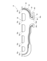
- FIG. 3 is a cross-sectional view of the exhaust manifold taken along line BB in FIG. 2.
- FIG. 1 is a plan view showing an outline of an engine to which an exhaust manifold according to the embodiment is applied and its intake and exhaust system
- FIG. 2 is a side view showing an outline of an engine to which an exhaust manifold according to the embodiment is applied and its intake and exhaust system.
- an exhaust manifold 10 according to the embodiment is connected to a multi-cylinder engine 1 (internal combustion engine) mounted on a vehicle.
- the exhaust manifold 10 has a plurality of branch pipe sections 12 connected to each exhaust port of a plurality of cylinders 2 of the engine 1, and a collecting pipe section 14 where the plurality of branch pipe sections 12 join together.
- the exhaust manifold 10 discharges the exhaust gas of the engine 1 that has flowed into each branch pipe section 12 from the collecting pipe section 14.
- the arrangement direction of the plurality of cylinders 2 of the engine 1 is referred to as the "arrangement direction X".
- the engine 1 side in the flow of exhaust gas is referred to as the "upstream side”
- the opposite side to the engine 1 is referred to as the "downstream side”.
- the arrangement direction X corresponds to the front-rear direction of the vehicle on which the engine 1 is mounted.
- the front side in Figure 1 and the top side in Figure 2 are the top side in the up-down direction.
- a turbocharger 3 is provided downstream of the collecting pipe section 14 of the exhaust manifold 10.
- the turbocharger 3 includes a first turbocharger 3A and a second turbocharger 3B.
- the first turbocharger 3A has a first turbine 3AT and a first compressor 3AC.
- the second turbocharger 3B has a second turbine 3BT and a second compressor 3BC, and is connected to the first turbocharger 3A.
- the second turbocharger 3B is a turbocharger having a different weight from the first turbocharger 3A, and is provided above the first turbocharger 3A.
- the first turbocharger 3A is mainly used in the low rotation range of the engine 1.
- the second turbocharger 3B is mainly used in the high rotation range of the engine 1, and is lighter in weight than the first turbocharger 3A.
- Exhaust gas discharged from the exhaust manifold 10 passes through the first turbine 3AT and the second turbine 3BT, and is discharged to the outside from the exhaust pipe 5 via the purification device 4 including a catalyst.
- the first turbine 3AT and the second turbine 3BT are rotated by the exhaust gas, and the first compressor 3AC and the second compressor 3BC are also rotated accordingly.
- air from the outside is sucked into the second compressor 3BC and the first compressor 3AC via the air cleaner 6 ( Figure 1), and is compressed and sent to the intake side of the engine 1 by the rotation of each compressor.
- An intercooler 7 for cooling the air is arranged between each compressor and the engine 1.
- Figures 3 to 5 are perspective views of the exhaust manifold 10 viewed from the downstream side and from above.
- the cover 40 which will be described later, is omitted from the state shown in Figure 3, and in Figure 5, the outer pipe 30, which will be described later, is further omitted from the state shown in Figure 4.
- Figures 6 and 7 are perspective views of the exhaust manifold 10 viewed from the upstream side and from above. In Figure 6, the cover 40 is omitted, and in Figure 7, the outer pipe 30 is further omitted from the state shown in Figure 6.
- Figure 8 is a cross-sectional view of the exhaust manifold 10 taken along line A-A in Figure 1
- Figure 9 is a cross-sectional view of the exhaust manifold 10 taken along line B-B in Figure 2.
- the exhaust manifold 10 includes an inner pipe 20, an outer pipe 30, a cover 40, a first flange portion 50, and a second flange portion 60 (flange portion).
- the exhaust manifold 10 extends so that the arrangement direction X of the cylinders 2 is the longitudinal direction.
- the inner pipe 20 has each branch pipe section 12 arranged at intervals along the arrangement direction X of the cylinders 2, and each branch pipe section 12 joins to form the collecting pipe section 14.
- the end 20a of the inner pipe 20 (the upstream end of each branch pipe section 12) has an opening that communicates with the exhaust port of each cylinder 2.
- the end 20b of the inner pipe 20 (the downstream end of the collecting pipe section 14) has an opening that communicates with the turbocharger 3 (the first turbine 3AT of the first turbocharger 3A).
- the outer pipe 30 is a hollow member that covers the inner pipe 20 from the outside, and is open at end 30a (the upstream end of each branch pipe section 12) and end 30b (the downstream end of the collecting pipe section 14).
- the outer pipe 30 is formed roughly along the outer circumferential surface of the inner pipe 20, and is provided at a distance from the outer circumferential surface of the inner pipe 20.
- an insulating layer of air is formed between the inner pipe 20 and the outer pipe 30, which reduces the temperature drop of the exhaust gas passing through the inner pipe 20 and suppresses thermal damage to surrounding equipment caused by the exhaust gas passing through the inner pipe 20.
- the cover 40 is a hollow member that further covers the outer pipe 30 from the outside, and is an insulator that has functions such as heat insulation and soundproofing.
- the cover 40 is formed in a shape that roughly follows the outer peripheral surface of the outer pipe 30, and is provided with a gap between it and the outer peripheral surface of the outer pipe 30.
- the cover 40 is joined to the outer peripheral surface of the outer pipe 30 via legs (not shown) that protrude from the outer peripheral surface of the outer pipe 30. As shown in FIG. 8, the cover 40 is provided so as to cover the rib portion 70 (described later) from the outside.
- An insulating material (not shown) is provided between the cover 40 and the outer pipe 30.
- the first flange portion 50 is a plate-like member extending along the arrangement direction X of the cylinders 2, and constitutes the attachment portion of the exhaust manifold 10 to the engine 1.
- the first flange portion 50 supports the inner pipe 20 and the outer pipe 30 in each branch pipe portion 12.
- the first flange portion 50 has a plurality of openings 50a formed at positions corresponding to each branch pipe portion 12 of the inner pipe 20.
- the end portion 20a of the inner pipe 20 is inserted (fitted) into the inner peripheral surface of the opening 50a, and at least a part of the end portion 20a is joined by spot welding to the inner peripheral surface of the opening 50a.
- the end portion 30a of the outer pipe 30 is thrust into the first flange portion 50 on the outside of the inner pipe 20 and abuts against it, and joined by welding.
- the second flange portion 60 is a plate-like member arranged opposite the first flange portion 50, and constitutes the attachment portion of the exhaust manifold 10 to the turbocharger 3 (the first turbine 3AT of the first turbocharger 3A).
- the second flange portion 60 is formed in a substantially triangular shape, but the shape of the second flange portion 60 is not limited to this, and may be, for example, a rectangular shape or a circular shape.
- the second flange portion 60 has an end face 601 on the upstream side (opposite the turbocharger 3) and an end face 602 on the downstream side (the turbocharger 3 side).
- a rib portion 70 is formed on the end face 601 of the second flange portion 60, protruding in an annular shape toward the upstream side around the opening 60a described later.
- the rib portion 70 has a longitudinal portion 71 extending along the arrangement direction X of the cylinders 2, and a short portion 72 extending along the vertical direction perpendicular to the longitudinal portion 71 and formed shorter than the longitudinal portion 71.
- the rib portion 70 has a generally elliptical shape with opposing long sides 71 and opposing short sides 72.
- the rib portion 70 has a different length (length from one end of the annular shape to the other end) in the arrangement direction X and in a direction perpendicular to the arrangement direction X and the flow direction of the exhaust gas (the vertical direction in this embodiment).
- the second flange portion 60 configured as described above supports the inner pipe 20 and the outer pipe 30 in the collecting pipe portion 14.
- the second flange portion 60 has an opening 60a that serves as an exhaust gas outlet at a position corresponding to the collecting pipe portion 14 of the inner pipe 20.
- the end portion 20b of the inner pipe 20 is inserted into the inner surface of this opening 60a (fitted in to the extent that it is not completely fixed). Therefore, the inner pipe 20 is provided without being fixed to the second flange portion 60 by welding or the like.
- the very end of the end portion 30a of the outer pipe 30 is thrust into and abuts against the end surface 601 of the second flange portion 60.
- the end portion 30a is inserted and supported by the inner surface of the rib portion 70, and is joined to the rib portion 70 by welding. Since the outer tube 30 has a larger diameter than the inner tube 20, it abuts against the second flange portion 60 radially outside the inner tube 20 (at a position spaced apart from the inner tube 20).
- the exhaust manifold 10 of the embodiment includes the inner pipe 20 through which exhaust gas from the engine 1 (internal combustion engine) flows, the outer pipe 30 that is spaced apart from the outer peripheral surface of the inner pipe 20 and forms a plurality of branch pipe sections 12 and a collecting pipe section 14 together with the inner pipe 20, and the second flange section 60 (flange section) that supports the inner pipe 20 and the outer pipe 30 in the collecting pipe section 14 and has an opening 60a formed therein that serves as an outlet for exhaust gas flowing through the inner pipe 20.
- the inner pipe 20 is inserted into the inner peripheral surface of the opening 60a of the second flange section 60, and the outer pipe 30 is abutted against the end face 601 of the second flange section 60 outside the inner pipe 20.
- the inner pipe 20 is inserted into the second flange portion 60, so even if thermal expansion occurs in the inner pipe 20, the connection between the inner pipe 20 and the second flange portion 60 is not released and deformation due to thermal expansion is absorbed. As a result, damage to the inner pipe 20 can be suppressed.
- the outer pipe 30 abuts against the end face 601 of the second flange portion 60, so that the force transmitted to the second flange portion 60 from the device (supercharger 3) arranged downstream of the exhaust manifold 10 can be received by the outer pipe 30.
- the outer pipe 30 abuts against the second flange portion 60 on the outside of the inner pipe 20, the force transmitted from the supercharger 3 to the second flange portion 60 can be suppressed from being transmitted to the inner pipe 20, and the force can be received by the outer pipe 30, which has a larger diameter than the inner pipe 20, improving durability. Furthermore, if the outer pipe 30 were inserted into the opening 60a in the same way as the inner pipe 20, the outer pipe 30 would need to be tapered toward the opening 60a, which would result in the outer pipe 30 having a portion (a portion of tapered diameter) where stress concentration is likely to occur.
- the second flange portion 60 also has a rib portion 70 that protrudes annularly from the end face 601 around the opening 60a, and the outer pipe 30 is inserted into the inner peripheral surface of the rib portion 70.
- the outer pipe 30 is stably supported by the rib portion 70, and the outer pipe 30 can be prevented from coming off the second flange portion 60.
- the outer pipe 30 is welded to the rib portion 70 after being inserted into the inner peripheral surface of the rib portion 70.
- the rib portion 70 also has a different length in the arrangement direction X and in a direction (up-down direction) perpendicular to the arrangement direction X and the flow direction of the exhaust gas.
- This configuration makes it possible to increase the rigidity in the rotational direction about the axis of the flow direction of the exhaust gas at the connection portion between the outer pipe 30 and the second flange portion 60. In other words, it is possible to improve the durability of the connection portion between the outer pipe 30 and the second flange portion 60 against vibrations and forces in a specific direction.
- the length of the rib portion 70 in the arrangement direction X (the length of the long side portion 71) is longer than the length in the direction perpendicular to the arrangement direction X and the flow direction of the exhaust gas (the length of the short side portion 72).
- the above-mentioned specific direction is the arrangement direction X.
- a first turbocharger 3A turbocharger including a first turbine 3AT (turbine) and a first compressor 3AC (compressor) aligned along the arrangement direction X of the cylinders 2 is provided downstream of the exhaust manifold 10, and the first turbine 3AT is attached to the second flange portion 60. That is, the first compressor 3AC is provided offset in the arrangement direction X from the second flange portion 60.
- the structure of this embodiment can improve the durability of the connection portion between the outer pipe 30 and the second flange portion 60 as described above, and appropriately protect the exhaust manifold 10.
- the turbocharger 3 includes a first turbocharger 3A attached to the second flange portion 60 and communicating with the exhaust manifold 10, and a second turbocharger 3B that is provided on one side of the first turbocharger 3A in the vertical direction and has a weight different from that of the first turbocharger 3A connected to the first turbocharger 3A. That is, the second turbocharger 3B is provided shifted to one side in the vertical direction from the second flange portion 60.
- the exhaust manifold 10 further includes a cover 40 that is spaced apart from the outer peripheral surface of the outer pipe 30, and the cover 40 is arranged to cover the rib portion 70 from the outside.
- the end portion 30b of the outer pipe 30 can be covered by the cover 40 and the rib portion 70, thereby improving the heat retention effect of the exhaust manifold 10 and the effect of suppressing heat damage to surrounding equipment.
- the part to which the second flange portion 60 is attached does not have to be the turbocharger 3 (i.e., the turbocharger 3 may be omitted).
- the rib portion 70 is not limited to an elliptical shape, and may be rectangular, etc.
- the rib portion 70 may be formed with both the long portion 71 and the short portion 72 having the same length. As long as the outer pipe 30 can be stably supported by the second flange portion 60, the rib portion 70 may be omitted from the second flange portion 60.
- the long portion 71 may be set in any direction taking into account the magnitude of the force applied to the exhaust manifold 10.
Landscapes
- Engineering & Computer Science (AREA)
- Chemical & Material Sciences (AREA)
- Combustion & Propulsion (AREA)
- Mechanical Engineering (AREA)
- General Engineering & Computer Science (AREA)
- Exhaust Silencers (AREA)
Priority Applications (2)
| Application Number | Priority Date | Filing Date | Title |
|---|---|---|---|
| JP2025561647A JPWO2025120844A1 (https=) | 2023-12-08 | 2023-12-08 | |
| PCT/JP2023/044016 WO2025120844A1 (ja) | 2023-12-08 | 2023-12-08 | 排気マニホールド |
Applications Claiming Priority (1)
| Application Number | Priority Date | Filing Date | Title |
|---|---|---|---|
| PCT/JP2023/044016 WO2025120844A1 (ja) | 2023-12-08 | 2023-12-08 | 排気マニホールド |
Publications (1)
| Publication Number | Publication Date |
|---|---|
| WO2025120844A1 true WO2025120844A1 (ja) | 2025-06-12 |
Family
ID=95979780
Family Applications (1)
| Application Number | Title | Priority Date | Filing Date |
|---|---|---|---|
| PCT/JP2023/044016 Pending WO2025120844A1 (ja) | 2023-12-08 | 2023-12-08 | 排気マニホールド |
Country Status (2)
| Country | Link |
|---|---|
| JP (1) | JPWO2025120844A1 (https=) |
| WO (1) | WO2025120844A1 (https=) |
Citations (2)
| Publication number | Priority date | Publication date | Assignee | Title |
|---|---|---|---|---|
| WO2007081669A2 (en) * | 2006-01-03 | 2007-07-19 | Metaldyne Company, Llc | Dual wall exhaust manifold and method of making same |
| JP2008240589A (ja) * | 2007-03-27 | 2008-10-09 | Kokusan Buhin Kogyo Kk | エンジンの排気構造 |
-
2023
- 2023-12-08 JP JP2025561647A patent/JPWO2025120844A1/ja active Pending
- 2023-12-08 WO PCT/JP2023/044016 patent/WO2025120844A1/ja active Pending
Patent Citations (2)
| Publication number | Priority date | Publication date | Assignee | Title |
|---|---|---|---|---|
| WO2007081669A2 (en) * | 2006-01-03 | 2007-07-19 | Metaldyne Company, Llc | Dual wall exhaust manifold and method of making same |
| JP2008240589A (ja) * | 2007-03-27 | 2008-10-09 | Kokusan Buhin Kogyo Kk | エンジンの排気構造 |
Also Published As
| Publication number | Publication date |
|---|---|
| JPWO2025120844A1 (https=) | 2025-06-12 |
Similar Documents
| Publication | Publication Date | Title |
|---|---|---|
| US8375707B2 (en) | Exhaust gas collector | |
| US8869525B2 (en) | Exhaust-gas turbocharger | |
| US20160186704A1 (en) | Exhaust gas recirculation system for engine | |
| CN1437680A (zh) | 具有旁通管和废气再循环阀的废气冷却器 | |
| CN107035467B (zh) | 发动机的消声器 | |
| CN87106314A (zh) | 废气管道的固定装置 | |
| JP4094423B2 (ja) | 内燃機関の排気装置 | |
| KR101547092B1 (ko) | 과급기용 사일런서 | |
| JP3497443B2 (ja) | 車両におけるエンジンの排気装置 | |
| WO2025120844A1 (ja) | 排気マニホールド | |
| US5666805A (en) | Emission control system for internal-combustion engines | |
| US6647714B1 (en) | Exhaust header system | |
| US9482140B2 (en) | Mounting system for aftertreatment component | |
| JP4506289B2 (ja) | 過給機および過給機付エンジン | |
| JP2011021573A (ja) | ターボチャージャ | |
| JP4877825B2 (ja) | Egrパイプ | |
| US7228684B2 (en) | Internal combustion engine | |
| US9719402B2 (en) | Exhaust runner collar | |
| US11795856B2 (en) | Exhaust gas purification device with improved air inlet nozzle | |
| JP2001263054A (ja) | 排気管 | |
| JP4088552B2 (ja) | Egrパイプ継手構造 | |
| JPH09280046A (ja) | エンジンの排気管構造 | |
| JP4709682B2 (ja) | エンジンの排気装置 | |
| JP2013148068A (ja) | 内燃機関 | |
| JP3900585B2 (ja) | 多気筒エンジンの排気装置 |
Legal Events
| Date | Code | Title | Description |
|---|---|---|---|
| 121 | Ep: the epo has been informed by wipo that ep was designated in this application |
Ref document number: 23960393 Country of ref document: EP Kind code of ref document: A1 |
|
| ENP | Entry into the national phase |
Ref document number: 2025561647 Country of ref document: JP Kind code of ref document: A |