WO2025120692A1 - 速度検知装置および速度検知方法 - Google Patents
速度検知装置および速度検知方法 Download PDFInfo
- Publication number
- WO2025120692A1 WO2025120692A1 PCT/JP2023/043275 JP2023043275W WO2025120692A1 WO 2025120692 A1 WO2025120692 A1 WO 2025120692A1 JP 2023043275 W JP2023043275 W JP 2023043275W WO 2025120692 A1 WO2025120692 A1 WO 2025120692A1
- Authority
- WO
- WIPO (PCT)
- Prior art keywords
- speed
- moving
- traveling direction
- moving body
- objects
- Prior art date
- Legal status (The legal status is an assumption and is not a legal conclusion. Google has not performed a legal analysis and makes no representation as to the accuracy of the status listed.)
- Pending
Links
Images





Classifications
-
- G—PHYSICS
- G01—MEASURING; TESTING
- G01P—MEASURING LINEAR OR ANGULAR SPEED, ACCELERATION, DECELERATION, OR SHOCK; INDICATING PRESENCE, ABSENCE, OR DIRECTION, OF MOVEMENT
- G01P3/00—Measuring linear or angular speed; Measuring differences of linear or angular speeds
- G01P3/36—Devices characterised by the use of optical means, e.g. using infrared, visible, or ultraviolet light
-
- G—PHYSICS
- G01—MEASURING; TESTING
- G01S—RADIO DIRECTION-FINDING; RADIO NAVIGATION; DETERMINING DISTANCE OR VELOCITY BY USE OF RADIO WAVES; LOCATING OR PRESENCE-DETECTING BY USE OF THE REFLECTION OR RERADIATION OF RADIO WAVES; ANALOGOUS ARRANGEMENTS USING OTHER WAVES
- G01S13/00—Systems using the reflection or reradiation of radio waves, e.g. radar systems; Analogous systems using reflection or reradiation of waves whose nature or wavelength is irrelevant or unspecified
- G01S13/02—Systems using reflection of radio waves, e.g. primary radar systems; Analogous systems
- G01S13/50—Systems of measurement based on relative movement of target
- G01S13/58—Velocity or trajectory determination systems; Sense-of-movement determination systems
- G01S13/60—Velocity or trajectory determination systems; Sense-of-movement determination systems wherein the transmitter and receiver are mounted on the moving object, e.g. for determining ground speed, drift angle, ground track
Definitions
- This disclosure relates to a speed detection device and a speed detection method for detecting the moving speed of a moving object.
- a method using a tachograph generator in a moving object detects a voltage proportional to the rotation of the wheel axle and can calculate the moving speed from the wheel diameter.
- a tachograph generator in a moving object such as a railway vehicle detects a voltage proportional to the rotation of the wheel axle and can calculate the moving speed from the wheel diameter.
- Patent Document 1 discloses technology relating to a speed measurement device that uses laser light to measure the moving speed of a railway vehicle. By using the speed measurement device described in Patent Document 1, it is possible to avoid speed errors caused by the effects of changes in wheel diameter, wheel skids, wheel slippage, and wheel spin.
- the railway vehicle irradiates laser light at an angle toward the ground.
- the laser light has a certain width.
- the present disclosure has been made in consideration of the above, and aims to provide a speed detection device that can improve the measurement accuracy of the moving speed of a moving object.
- the present disclosure provides a speed detection device that detects the moving speed of a moving body in the traveling direction.
- the speed detection device is characterized by comprising a sensor that irradiates an electromagnetic wave onto a road surface and detects an observation angle indicating the direction in which an object exists and the object relative speed of the object relative to the moving body at the observation angle based on a change in frequency of the reflected wave from an object on the road surface, and a calculation unit that calculates a detection angle indicating the direction in which the object exists relative to the traveling direction of the moving body from the mounting angle of the sensor with respect to the traveling direction of the moving body and the observation angle, and calculates the moving speed of the moving body in the traveling direction by correcting the object relative speed using the detection angle.
- the speed detection device disclosed herein has the effect of improving the measurement accuracy of the moving speed of a moving object.
- FIG. 1 is a diagram showing a configuration example of a speed detection device according to a first embodiment
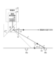
- FIG. 1 is a diagram showing a method for calculating the moving speed in the traveling direction of a moving object in the speed detection device according to the first embodiment
- 1 is a flowchart showing the operation of the speed detection device according to the first embodiment.
- FIG. 1 is a diagram showing an example of a processing circuit for implementing a speed detection device according to a first embodiment, the processing circuit being configured with a processor and a memory
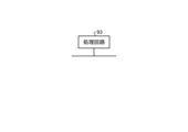
- FIG. 1 is a diagram showing an example in which a processing circuit for realizing a speed detection device according to a first embodiment is configured with dedicated hardware.
- FIG. 1 is a diagram showing a configuration example of a speed detection device according to a first embodiment
- FIG. 1 is a diagram showing a method for calculating the moving speed in the traveling direction of a moving object in the speed detection device according to the first embodiment
- 1 is a flowchart showing the operation of the speed detection device according to the first embodiment
- FIG. 13 is a diagram showing an example of a selection method in which the speed detection device according to the second embodiment selects an object based on the reflection level of a reflected wave.
- FIG. 13 is a diagram showing an image of calculating the moving speed in the traveling direction of a moving object for an object present at an effective detection point position by the speed detection device according to the second embodiment; 11 is a flowchart showing the operation of the speed detection device according to the second embodiment.
- FIG. 13 is a diagram showing a configuration example of a speed detection device according to a third embodiment;
- Fig. 1 is a diagram showing a configuration example of a speed detection device 20 according to a first embodiment.
- the speed detection device 20 is mounted on a moving body 10 and detects a moving speed V in a traveling direction of the moving body 10.
- the moving body 10 is, for example, a railroad car, an automobile, etc., but is not limited thereto.
- the configuration and operation of the speed detection device 20 will be described.
- the speed detection device 20 includes a sensor 30 and a calculation unit 40.
- the sensor 30 comprises an antenna 31 and a processing unit 32.
- the antenna 31 irradiates the road surface with frequency-modulated electromagnetic waves and receives reflected waves from objects on the road surface.
- the antenna 31 may be composed of multiple antennas with different uses, such as an antenna that irradiates electromagnetic waves and an antenna that receives reflected waves from objects, or may be composed of multiple antennas, each capable of irradiating electromagnetic waves and receiving reflected waves.
- the processing unit 32 detects the observation angle ⁇ indicating the direction in which the object is located, the distance r between the antenna 31, i.e., the sensor 30, and the object, and the object relative speed u of the object with respect to the moving body 10 at the observation angle ⁇ , based on the frequency change of the reflected wave received by the antenna 31.
- the processing unit 32 outputs the detected observation angle ⁇ , distance r, and object relative speed u to the calculation unit 40.
- the processing unit 32 may not detect the distance r, or may not output the distance r to the calculation unit 40 when the processing unit 32 detects the distance r.
- the sensor 30 may be configured such that the entire sensor 30 or the antenna 31 is provided outside the moving body 10.
- the sensor 30 may also include only the antenna 31, and the function of the processing unit 32 may be provided in the calculation unit 40.
- the sensor 30 is, for example, a non-contact speed sensor using radar technology that is used as a sensor for preventing automobile collisions.
- the calculation unit 40 calculates a detection angle ⁇ indicating the direction in which the object is present relative to the traveling direction of the moving body 10 from the mounting angle ⁇ and observation angle ⁇ of the sensor 30 relative to the traveling direction of the moving body 10.
- the calculation unit 40 also uses the detection angle ⁇ to correct the object relative speed u and calculates the moving speed V of the moving body 10 in the traveling direction.
- FIG. 2 is a diagram showing a method of calculating the moving speed V in the traveling direction of the moving body 10 in the speed detection device 20 according to the first embodiment.
- FIG. 2 shows, as an example, a configuration of the speed detection device 20 in which the entire sensor 30 is provided outside the moving body 10.
- the sensor 30 is installed under the floor of the railway vehicle in a position where it can irradiate electromagnetic waves to the railroad tracks, sleepers, etc. Also, FIG.
- the object 50 shows a state in which objects 50a and 50b are present, and the electromagnetic wave irradiated from the sensor 30 is reflected by the object 50b, and the sensor 30 receives the reflected wave from the object 50b.
- the objects 50a and 50b are not distinguished, they may be referred to as the object 50.
- ⁇ is the mounting angle of the sensor 30 relative to the traveling direction of the moving body 10
- ⁇ is the observation angle of the sensor 30 indicating the direction in which the object 50b observed by the sensor 30 exists
- ⁇ is the detection angle indicating the direction in which the object 50b exists relative to the traveling direction of the moving body 10.
- the observation angle ⁇ is the angle between the sensor vertical axis direction indicated by the dotted line and the direction in which the object 50b exists.
- u is the object relative speed of the object 50b with respect to the moving body 10 at the observation angle ⁇
- r is the distance between the sensor 30 and the object 50b
- V0 is the ground speed of the object 50b with respect to the moving body 10
- V is the moving speed in the traveling direction of the moving body 10 that is the same magnitude as the ground speed V0 but directed in the opposite direction to the ground speed V0.
- the sensor 30 can detect the observation angle ⁇ indicating the direction in which the object 50b is located, the distance r between the sensor 30 and the object 50b, and the object relative speed u of the object 50b with respect to the moving body 10 at the observation angle ⁇ .
- the sensor 30 outputs information on the observation angle ⁇ , distance r, and object relative speed u detected for the object 50b to the calculation unit 40.
- the calculation unit 40 uses the formula (1) to calculate the detection angle ⁇ indicating the direction in which the target object 50b exists relative to the traveling direction of the moving body 10 from the mounting angle ⁇ and observation angle ⁇ of the sensor 30 relative to the traveling direction of the moving body 10.
- the detection angle ⁇ is an angle indicating the direction in which the object 50b exists relative to the traveling direction of the moving body 10, and is also the angle between the direction of the ground speed V0 and the direction of the object relative speed u.
- the ground speed V0 and the object relative speed u have a cos ⁇ relationship.
- the calculation unit 40 can calculate the ground speed V0 from the object relative speed u and the detection angle ⁇ using equation (2), and calculate the moving speed V in the traveling direction of the moving body 10 by reversing the direction of the ground speed V0.
- step S101 the antenna 31 of the sensor 30 irradiates a frequency-modulated electromagnetic wave.
- the antenna 31 receives a reflected wave, which is an electromagnetic wave reflected by the object 50, from the object 50 (step S102).
- the processing unit 32 of the sensor 30 detects the object relative speed u of the object 50 with respect to the moving body 10 at the observation angle ⁇ based on the frequency change of the reflected wave received by the antenna 31 (step S103).
- the processing unit 32 can detect the object relative speed u, for example, by performing an FFT (Fast Fourier Transform) transformation on the reflected wave, but is not limited to this, and the object relative speed u may be detected by other processing methods.
- the processing unit 32 detects the observation angle ⁇ , which is the direction from which the reflected wave arrives, based on the phase difference generated in each antenna (step S104).
- the calculation unit 40 calculates a detection angle ⁇ indicating the direction in which the object 50 exists relative to the traveling direction of the moving body 10 from the mounting angle ⁇ and observation angle ⁇ of the sensor 30 relative to the traveling direction of the moving body 10 (step S105).
- the calculation unit 40 calculates a ground speed V0 from the object relative speed u and the detection angle ⁇ , and calculates the moving speed V in the traveling direction of the moving body 10 by reversing the direction of the ground speed V0 (step S106).
- the antenna 31 of the sensor 30 is an antenna element.
- the processing unit 32 and the calculation unit 40 of the sensor 30 are realized by a processing circuit.
- the processing circuit may be a processor and memory that executes a program stored in a memory, or may be dedicated hardware.
- FIG. 4 is a diagram showing an example of a processing circuit 90 for implementing the speed detection device 20 according to the first embodiment, which is configured with a processor 91 and a memory 92.
- each function of the processing circuit 90 of the speed detection device 20 is implemented by software, firmware, or a combination of software and firmware.
- the software or firmware is written as a program and stored in the memory 92.
- each function is implemented by the processor 91 reading and executing the program stored in the memory 92. That is, the processing circuit 90 includes a memory 92 for storing a program that will result in the processing of the speed detection device 20 being executed. It can also be said that these programs cause a computer to execute the procedures and methods of the speed detection device 20.
- the above program can also be said to be a program that causes the speed detection device 20 to execute a first step in which the sensor 30 irradiates the road surface with electromagnetic waves and detects the observation angle ⁇ indicating the direction in which the object 50 exists and the object relative speed u of the object 50 with respect to the moving body 10 at the observation angle ⁇ based on the frequency change of the reflected wave from the object 50 existing on the road surface, and a second step in which the calculation unit 40 calculates a detection angle ⁇ indicating the direction in which the object 50 exists with respect to the moving direction of the moving body 10 from the mounting angle ⁇ of the sensor 30 with respect to the moving direction of the moving body 10 and the observation angle ⁇ , and corrects the object relative speed u using the detection angle ⁇ to calculate the moving speed V of the moving body 10 in the moving direction.
- the processor 91 may be a CPU (Central Processing Unit), a processing device, an arithmetic unit, a microprocessor, a microcomputer, or a DSP (Digital Signal Processor).
- the memory 92 may be, for example, a RAM (Random Access Memory), a ROM (Read Only Memory), a flash memory, an EPROM (Erasable Programmable ROM), an EEPROM (Electrically EPROM), or other non-volatile or volatile semiconductor memory, a magnetic disk, a flexible disk, an optical disk, a compact disk, a mini disk, or a DVD (Digital Versatile Disc).
- FIG. 5 is a diagram showing an example in which the processing circuit 93 that realizes the speed detection device 20 according to the first embodiment is configured with dedicated hardware.
- the processing circuit 93 shown in FIG. 5 corresponds to, for example, a single circuit, a composite circuit, a programmed processor, a parallel programmed processor, an ASIC (Application Specific Integrated Circuit), an FPGA (Field Programmable Gate Array), or a combination of these.
- Each function of the speed detection device 20 may be realized by the processing circuit 93 on a function-by-function basis, or each function may be realized collectively by the processing circuit 93.
- the speed detection device 20 may be realized by dedicated hardware and some by software or firmware.
- the processing circuit can realize each of the above-mentioned functions by dedicated hardware, software, firmware, or a combination of these.
- the sensor 30 irradiates the road surface with frequency-modulated electromagnetic waves, receives reflected waves from the object 50 on the road surface, and detects the observation angle ⁇ indicating the direction in which the object 50 exists and the object relative speed u of the object 50 relative to the moving body 10 at the observation angle ⁇ based on the frequency change of the reflected waves.
- the calculation unit 40 calculates the detection angle ⁇ indicating the direction in which the object 50 exists relative to the moving direction of the moving body 10 from the mounting angle ⁇ and observation angle ⁇ of the sensor 30 relative to the traveling direction of the moving body 10, and calculates the moving speed V of the moving body 10 in the traveling direction by correcting the object relative speed u using the detection angle ⁇ .
- the speed detection device 20 can accurately detect the arrival direction of the reflected waves, i.e., the direction of the object 50 reflecting the electromagnetic waves, thereby improving the measurement accuracy of the moving speed V in the traveling direction of the moving body 10. It can also be said that the speed detection device 20 can improve the calculation accuracy of the moving speed V in the traveling direction of the moving body 10. The same applies hereafter.
- the speed detection device 20 can reduce the effects of errors and improve the measurement accuracy of the moving speed V, there is no need to narrow the angle of the electromagnetic waves emitted from the antenna 31 to reduce errors, and the electromagnetic waves can be emitted over a wide range, reducing the occurrence of missing measurements.
- the speed detection device 20 targets one object 50, i.e., calculates the moving speed V in the traveling direction of the moving body 10 using reflected waves from one object 50.
- the speed detection device 20 targets multiple objects 50, i.e., calculates the moving speed V in the traveling direction of the moving body 10 using reflected waves from multiple objects 50.
- the configuration of the speed detection device 20 is the same as the configuration of the speed detection device 20 of the first embodiment shown in FIG. 1.
- the speed detection device 20 received reflected waves only from the object 50b.
- the speed detection device 20 can increase the number of objects 50 for which the observation angle ⁇ , the object relative speed u, etc. can be detected.
- the processing unit 32 of the sensor 30 can detect the observation angle ⁇ , the distance r, and the object relative speed u for each of the multiple objects 50 present on the road surface by performing the same processing as in the first embodiment for each object 50.
- the calculation unit 40 calculates the moving speed Vn in the traveling direction of the moving body 10 for each of the multiple objects 50, and finally calculates the moving speed V in the traveling direction of the moving body 10 using the calculated moving speed Vn in the traveling direction of the moving body 10 for each of the multiple objects 50.
- the calculation unit 40 may smooth the moving speed Vn in the traveling direction of the moving body 10 calculated for each of the multiple objects 50, or perform statistical filtering processing to finally calculate the moving speed V in the traveling direction of the moving body 10.
- smoothing for example, an averaging method is available, but this is not limited to this, and other methods may be used.
- statistical filtering for example, the application of a Kalman filter is considered, but weighting may be applied to information about each object 50 depending on the magnitude of the reflection level.
- the speed detection device 20 can improve the measurement accuracy by smoothing the moving speed Vn in the traveling direction of the moving body 10 as the number of objects 50 increases, but the processing load also increases. Therefore, when there are multiple objects 50 for which it is possible to calculate the moving speed Vn in the traveling direction of the moving body 10, the speed detection device 20 may select several objects 50 from the multiple objects 50 and calculate the moving speed Vn in the traveling direction of the moving body 10 for the selected objects 50.
- Methods for the speed detection device 20 to select several objects 50 from the multiple objects 50 include, for example, a method of selecting based on a reflection level indicating the intensity of the reflected wave, and a method of selecting using an observation angle ⁇ , a distance r, etc. to limit the range in which the objects 50 exist.
- FIG. 6 is a diagram showing an example of a selection method in which the speed detection device 20 according to the second embodiment selects an object 50 based on the reflection level of a reflected wave. Note that in FIG. 6, for the sake of simplicity, only the sensor 30 of the speed detection device 20 is shown, but the positional relationship between the speed detection device 20 and the object 50 is the same as that in FIG. 2.
- the antenna 31 or processing unit 32 of the sensor 30 measures the reflection level indicating the intensity of the reflected wave received by the antenna 31.
- the processing unit 32 outputs information on the reflection level to the calculation unit 40 along with the detected observation angle ⁇ , the object relative speed u, etc.
- the calculation unit 40 selects one or more objects 50 to be used in calculating the moving speed Vn from the multiple objects 50 based on the reflection level indicating the intensity of the reflected wave, and calculates the moving speed Vn in the traveling direction of the moving body 10.
- Each point shown in the upper diagram of Figure 6 is a detection point indicating the point where the electromagnetic wave irradiated from the sensor 30 is reflected.
- Each detection point is an object 50 that can be used as a calculation target in the speed detection device 20.
- the processing load increases when the calculation unit 40 calculates the moving speed Vn in the traveling direction of the moving body 10 for all objects 50.
- the calculation unit 40 regards the objects 50 with a reflection level within a specified range, in the example of FIG. 6, as objects 50c, 50d, and 50e that are within the effective reflection level range shown in the lower diagram of FIG. 6, as being included in the effective detection point positions, and calculates the moving speed Vn in the traveling direction of the moving body 10 using the observation angle ⁇ , object relative speed u, etc. detected for the objects 50c, 50d, and 50e.
- the calculation unit 40 can also identify the valid detection point positions shown in the lower diagram of FIG. 6 using the observation angle ⁇ , distance r, etc. without using the reflection level. Therefore, the calculation unit 40 can select one or more objects 50 to be used in calculating the moving speed Vn from the multiple objects 50 using at least one of the observation angle ⁇ and distance r detected by the sensor 30, and calculate the moving speed Vn in the traveling direction of the moving body 10.
- the calculation unit 40 can also use the reflection level to identify the valid detection point positions shown in the lower diagram of FIG. 6, and can also select one or more objects 50 to be used in calculating the moving speed Vn from the multiple objects 50 using at least one of the observation angle ⁇ and distance r detected by the sensor 30.
- Figure 7 is a diagram showing an image of the speed detection device 20 according to embodiment 2 calculating the moving speed Vn in the traveling direction of the moving body 10 for the objects 50c, 50d, and 50e that are present at the effective detection point position. Note that in Figure 7, as in Figure 6, only the sensor 30 of the speed detection device 20 is shown for the sake of simplicity, but the positional relationship between the speed detection device 20 and the object 50 is the same as that in Figure 2.
- the calculation unit 40 calculates the moving speed V1 in the traveling direction of the moving body 10 for the object 50c by using the observation angle ⁇ 1 and object relative speed u1 detected by the sensor 30 for the object 50c.
- the calculation unit 40 also calculates the moving speed V2 in the traveling direction of the moving body 10 for the object 50d by using the observation angle ⁇ 2 and object relative speed u2 detected by the sensor 30 for the object 50d.
- the calculation unit 40 also calculates the moving speed V3 of the moving body 10 in the traveling direction of the object 50e by using the observation angle ⁇ 3 and the object relative speed u3 detected by the sensor 30 for the object 50e.
- the speed detection device 20 can also determine the distances r1, r2, and r3 for each of the objects 50c, 50d, and 50e, as shown in FIG. 7.
- the calculation unit 40 can finally calculate the moving speed V in the traveling direction of the moving body 10 by smoothing the moving speeds V1, V2, and V3.
- the calculation unit 40 may also calculate the moving speed V in the traveling direction of the moving body 10 by performing statistical filtering processing as described above. This allows the calculation unit 40 to reduce the influence of errors even when the observation angle ⁇ for a certain object 50 contains an error and the moving speed Vn is calculated using the observation angle ⁇ containing the error.
- the calculation unit 40 may finally calculate the moving speed V in the traveling direction of the moving body 10 by smoothing the moving speed Vn in the traveling direction of the moving body 10 calculated for each of the multiple objects 50 or by performing statistical filtering processing.
- the "n" of the moving speed Vn represents the “1", “2", and “3" of the moving speeds V1, V2, and V3 shown in FIG. 7, and is a natural number equal to or greater than 1. That is, in the example of Figure 7, the n of the moving speed Vn is 1, 2, and 3.
- the calculation unit 40 may also notify the sensor 30 of information on the valid detection point position where the selected object 50 exists. This allows the antenna 31 of the sensor 30 to irradiate electromagnetic waves to the range where the object 50 selected by the calculation unit 40 exists, i.e., the specified range including the valid detection point position.
- FIG. 8 is a flowchart showing the operation of the speed detection device 20 according to the second embodiment.
- the operations of steps S101 and S102 are the same as those of steps S101 and S102 in the flowchart of the first embodiment shown in FIG. 3.
- the processing unit 32 of the sensor 30 detects the object relative speed u of the object 50 at the observation angle ⁇ with respect to the moving body 10 for each object 50 based on the frequency change of the reflected wave received by the antenna 31 (step S201).
- the processing unit 32 detects the observation angle ⁇ , which is the direction from which the reflected wave arrives, for each object 50 based on the phase difference generated at each antenna (step S202).
- the calculation unit 40 selects one or more objects 50 to be used in the calculation of the moving speed V from the multiple objects 50 (step S203). For each selected object 50, the calculation unit 40 calculates a detection angle ⁇ indicating the direction in which the object 50 exists relative to the moving direction of the moving body 10 from the mounting angle ⁇ and observation angle ⁇ of the sensor 30 relative to the moving direction of the moving body 10 (step S204). For each selected object 50, the calculation unit 40 calculates a ground speed V0 from the object relative speed u and the detection angle ⁇ , and calculates a moving speed Vn in the moving direction of the moving body 10 by reversing the direction of the ground speed V0 (step S205). The calculation unit 40 finally calculates the moving speed V in the moving direction of the moving body 10 using the moving speed Vn in the moving direction of the moving body 10 calculated for each selected object 50 (step S206).
- step S203 the operation of step S203 can be deleted, and in steps S204 to S206, the calculation unit 40 targets all objects 50.
- the calculation unit 40 does not select one or more objects 50 from the multiple objects 50 to be used in calculating the moving speed V, that is, the calculation unit 40 calculates the moving speed V in the traveling direction of the moving body 10 for all objects 50.
- the sensor 30 detects the observation angle ⁇ and the object relative speed u for each of the multiple objects 50 present on the road surface by irradiating a wide range of frequency-modulated electromagnetic waves.
- the calculation unit 40 calculates the moving speed Vn for each of the multiple objects 50, or for each object 50 selected from the multiple objects 50, and calculates the moving speed V in the traveling direction of the moving body 10 using the calculated moving speed Vn for each of the multiple objects 50, or for each selected object 50.
- This allows the speed detection device 20 to further improve the measurement accuracy of the moving speed V in the traveling direction of the moving body 10 compared to embodiment 1.
- the speed detection device 20 can reduce the influence of the error.
- the speed detection device 20 can grasp the position of the detection point that is the target object 50, detection points in a range where the target object 50 cannot exist may be excluded as false detection points. This allows the speed detection device 20 to further improve the measurement accuracy of the moving speed V in the traveling direction of the moving body 10. For example, in FIG. 6, many detection points are shown in the upper diagram of FIG. 6, but detection points that exist underground or alone in the air are considered to be highly likely to be false detection points. Therefore, the calculation unit 40 of the speed detection device 20 can exclude such detection points from candidates when selecting the target object 50.
- the method of selecting the object 50 was described as being based on the reflection level, and the method of selecting using at least one of the observation angle ⁇ and the distance r detected by the sensor 30, but the method of selecting the object 50 is not limited to these methods. Furthermore, these selection methods can be applied to applications other than the application of selecting the object 50 and calculating the moving speed V in the traveling direction of the moving body 10.
- Embodiment 3 In the third embodiment, a case will be described in which the speed detection device 20 includes a plurality of sensors 30.
- the speed detection device 20 includes a plurality of sensors 30 and a calculation unit 40.
- the plurality of sensors 30 are mounted on different railway vehicles in one train formation.
- Each of the plurality of sensors 30 includes an antenna 31 and a processing unit 32, and performs the operation described in the first or second embodiment.
- the calculation unit 40 performs the operation described in the first or second embodiment for the information acquired from each sensor 30.
- the calculation unit 40 further smoothes the moving speed V in the traveling direction of the moving body 10 calculated for each sensor 30, or performs a statistical filtering process, thereby finally calculating the moving speed V in the traveling direction of the moving body 10.
- the number of sensors 30 included in the speed detection device 20 in FIG. 9 is three, the number is not limited to three.
- the speed detection device 20 may be configured to include two or four or more sensors 30.
- the speed detection device 20 performs the operation of the flowchart of the first embodiment shown in FIG. 3 or the operation of the flowchart of the second embodiment shown in FIG. 8 for each sensor 30, and finally, the moving speed V in the traveling direction of the moving body 10 is obtained by smoothing the moving speed V in the traveling direction of the moving body 10 obtained by calculation for each sensor 30, thereby finally obtaining the moving speed V in the traveling direction of the moving body 10. Therefore, the flowchart showing the operation of the third embodiment is omitted.
- the speed detection device 20 includes a plurality of sensors 30.
- the calculation unit 40 calculates the moving speed V in the traveling direction of the moving body 10 for each of the plurality of sensors 30 using the observation angle ⁇ and the object relative speed u detected by each of the plurality of sensors 30.
- the calculation unit 40 smoothes the moving speed V for each of the plurality of sensors 30 or performs statistical filtering processing, thereby finally calculating the moving speed V in the traveling direction of the moving body 10.
- the speed detection device 20 can further improve the measurement accuracy of the moving speed V in the traveling direction of the moving body 10 compared to the first and second embodiments.
Landscapes
- Engineering & Computer Science (AREA)
- Radar, Positioning & Navigation (AREA)
- Remote Sensing (AREA)
- Physics & Mathematics (AREA)
- General Physics & Mathematics (AREA)
- Computer Networks & Wireless Communication (AREA)
- Electromagnetism (AREA)
- Power Engineering (AREA)
- Radar Systems Or Details Thereof (AREA)
Priority Applications (2)
| Application Number | Priority Date | Filing Date | Title |
|---|---|---|---|
| JP2025561520A JPWO2025120692A1 (https=) | 2023-12-04 | 2023-12-04 | |
| PCT/JP2023/043275 WO2025120692A1 (ja) | 2023-12-04 | 2023-12-04 | 速度検知装置および速度検知方法 |
Applications Claiming Priority (1)
| Application Number | Priority Date | Filing Date | Title |
|---|---|---|---|
| PCT/JP2023/043275 WO2025120692A1 (ja) | 2023-12-04 | 2023-12-04 | 速度検知装置および速度検知方法 |
Publications (1)
| Publication Number | Publication Date |
|---|---|
| WO2025120692A1 true WO2025120692A1 (ja) | 2025-06-12 |
Family
ID=95979732
Family Applications (1)
| Application Number | Title | Priority Date | Filing Date |
|---|---|---|---|
| PCT/JP2023/043275 Pending WO2025120692A1 (ja) | 2023-12-04 | 2023-12-04 | 速度検知装置および速度検知方法 |
Country Status (2)
| Country | Link |
|---|---|
| JP (1) | JPWO2025120692A1 (https=) |
| WO (1) | WO2025120692A1 (https=) |
Citations (9)
| Publication number | Priority date | Publication date | Assignee | Title |
|---|---|---|---|---|
| JPS5940281A (ja) * | 1982-08-31 | 1984-03-05 | Mitsubishi Electric Corp | 車輛用対地速度検出装置 |
| JPH02287178A (ja) * | 1989-04-27 | 1990-11-27 | Matsushita Electric Works Ltd | 車載用レーダシステム |
| JP2014235140A (ja) * | 2013-06-05 | 2014-12-15 | 公益財団法人鉄道総合技術研究所 | 速度計測装置 |
| JP2015506474A (ja) * | 2012-01-05 | 2015-03-02 | ローベルト ボッシュ ゲゼルシャフト ミット ベシュレンクテル ハフツング | 車両における車輪に依存しない速度測定のための方法及び装置 |
| JP2016118406A (ja) * | 2014-12-18 | 2016-06-30 | パナソニックIpマネジメント株式会社 | レーダ装置及びレーダ状態推定方法 |
| JP2018025485A (ja) * | 2016-08-10 | 2018-02-15 | パナソニックIpマネジメント株式会社 | レーダ設置角度算出装置、レーダ装置およびレーダ設置角度算出方法 |
| JP2019007926A (ja) * | 2017-06-28 | 2019-01-17 | 本田技研工業株式会社 | 検出装置 |
| US20200209402A1 (en) * | 2018-12-31 | 2020-07-02 | Lyft, Inc. | Systems and methods for estimating vehicle speed based on radar |
| JP2022017795A (ja) * | 2020-07-14 | 2022-01-26 | Jrcモビリティ株式会社 | 移動速度の検出装置および検出方法 |
Family Cites Families (3)
| Publication number | Priority date | Publication date | Assignee | Title |
|---|---|---|---|---|
| JP4827956B2 (ja) * | 2009-09-18 | 2011-11-30 | 三菱電機株式会社 | 車載用レーダ装置 |
| US20160161609A1 (en) * | 2014-12-05 | 2016-06-09 | Panasonic Intellectual Property Management Co., Ltd. | Object detection device, velocity detection device, and vehicle |
| DE102020206771A1 (de) * | 2020-05-29 | 2021-12-02 | Siemens Mobility GmbH | Verfahren zum Schätzen einer Eigengeschwindigkeit |
-
2023
- 2023-12-04 WO PCT/JP2023/043275 patent/WO2025120692A1/ja active Pending
- 2023-12-04 JP JP2025561520A patent/JPWO2025120692A1/ja active Pending
Patent Citations (9)
| Publication number | Priority date | Publication date | Assignee | Title |
|---|---|---|---|---|
| JPS5940281A (ja) * | 1982-08-31 | 1984-03-05 | Mitsubishi Electric Corp | 車輛用対地速度検出装置 |
| JPH02287178A (ja) * | 1989-04-27 | 1990-11-27 | Matsushita Electric Works Ltd | 車載用レーダシステム |
| JP2015506474A (ja) * | 2012-01-05 | 2015-03-02 | ローベルト ボッシュ ゲゼルシャフト ミット ベシュレンクテル ハフツング | 車両における車輪に依存しない速度測定のための方法及び装置 |
| JP2014235140A (ja) * | 2013-06-05 | 2014-12-15 | 公益財団法人鉄道総合技術研究所 | 速度計測装置 |
| JP2016118406A (ja) * | 2014-12-18 | 2016-06-30 | パナソニックIpマネジメント株式会社 | レーダ装置及びレーダ状態推定方法 |
| JP2018025485A (ja) * | 2016-08-10 | 2018-02-15 | パナソニックIpマネジメント株式会社 | レーダ設置角度算出装置、レーダ装置およびレーダ設置角度算出方法 |
| JP2019007926A (ja) * | 2017-06-28 | 2019-01-17 | 本田技研工業株式会社 | 検出装置 |
| US20200209402A1 (en) * | 2018-12-31 | 2020-07-02 | Lyft, Inc. | Systems and methods for estimating vehicle speed based on radar |
| JP2022017795A (ja) * | 2020-07-14 | 2022-01-26 | Jrcモビリティ株式会社 | 移動速度の検出装置および検出方法 |
Also Published As
| Publication number | Publication date |
|---|---|
| JPWO2025120692A1 (https=) | 2025-06-12 |
Similar Documents
| Publication | Publication Date | Title |
|---|---|---|
| AU2012217286B2 (en) | Method for the autonomous localization of a driverless, motorized vehicle | |
| CA3120498C (en) | Vehicle odometry and motion direction determination | |
| US11009348B2 (en) | Structure measuring device, measurement point correcting device, and measurement point correcting method | |
| US20150070207A1 (en) | Method and Apparatus For Self Calibration of A Vehicle Radar System | |
| JP4593468B2 (ja) | レーダ装置 | |
| JP5122536B2 (ja) | レーダ装置 | |
| JP6305575B2 (ja) | 列車位置検知装置 | |
| JPWO2019181448A1 (ja) | レーダ装置 | |
| JP2019151227A (ja) | 列車位置推定装置 | |
| US11774573B2 (en) | System and method to determine low-speed and stationary state of a rail vehicle | |
| US7330148B2 (en) | Measuring apparatus and measuring method | |
| JP5422322B2 (ja) | レール変位量測定におけるレール検出方法およびレール変位量測定装置 | |
| ES3047882T3 (en) | Method for estimating an intrinsic speed | |
| CN106405535B (zh) | 列车速度检测装置及列车速度检测方法 | |
| WO2025120692A1 (ja) | 速度検知装置および速度検知方法 | |
| JP2009198362A (ja) | 移動体の速度測定装置及び速度測定方法 | |
| JP5677275B2 (ja) | レーダ装置及び車両 | |
| JP6494538B2 (ja) | 限界測定装置及び限界測定プログラム | |
| TW201704068A (zh) | 列車位置檢測裝置及列車位置檢測方法 | |
| JP2015165754A (ja) | 列車速度検出装置及び列車速度検出方法 | |
| CN112526498B (zh) | 车辆以及车载雷达的目标检测方法和装置 | |
| US11262441B2 (en) | Object detection apparatus, object detection method, and computer-readable recording medium | |
| CN106394616A (zh) | 列车位置检测装置及列车位置检测方法 | |
| TWI666463B (zh) | 列車速度檢測裝置及列車速度檢測方法 | |
| JP6219335B2 (ja) | 列車状態検出装置及び列車状態検出方法 |
Legal Events
| Date | Code | Title | Description |
|---|---|---|---|
| 121 | Ep: the epo has been informed by wipo that ep was designated in this application |
Ref document number: 23960710 Country of ref document: EP Kind code of ref document: A1 |
|
| ENP | Entry into the national phase |
Ref document number: 2025561520 Country of ref document: JP Kind code of ref document: A |
|
| WWE | Wipo information: entry into national phase |
Ref document number: 2025561520 Country of ref document: JP |