WO2025115653A1 - 粒子径分布測定システム、粒子径分布測定方法及び粒子径分布測定プログラム - Google Patents
粒子径分布測定システム、粒子径分布測定方法及び粒子径分布測定プログラム Download PDFInfo
- Publication number
- WO2025115653A1 WO2025115653A1 PCT/JP2024/040664 JP2024040664W WO2025115653A1 WO 2025115653 A1 WO2025115653 A1 WO 2025115653A1 JP 2024040664 W JP2024040664 W JP 2024040664W WO 2025115653 A1 WO2025115653 A1 WO 2025115653A1
- Authority
- WO
- WIPO (PCT)
- Prior art keywords
- particle size
- size distribution
- sample
- unit
- flow path
- Prior art date
- Legal status (The legal status is an assumption and is not a legal conclusion. Google has not performed a legal analysis and makes no representation as to the accuracy of the status listed.)
- Pending
Links
Images




Classifications
-
- G—PHYSICS
- G01—MEASURING; TESTING
- G01N—INVESTIGATING OR ANALYSING MATERIALS BY DETERMINING THEIR CHEMICAL OR PHYSICAL PROPERTIES
- G01N1/00—Sampling; Preparing specimens for investigation
-
- G—PHYSICS
- G01—MEASURING; TESTING
- G01N—INVESTIGATING OR ANALYSING MATERIALS BY DETERMINING THEIR CHEMICAL OR PHYSICAL PROPERTIES
- G01N1/00—Sampling; Preparing specimens for investigation
- G01N1/02—Devices for withdrawing samples
- G01N1/10—Devices for withdrawing samples in the liquid or fluent state
-
- G—PHYSICS
- G01—MEASURING; TESTING
- G01N—INVESTIGATING OR ANALYSING MATERIALS BY DETERMINING THEIR CHEMICAL OR PHYSICAL PROPERTIES
- G01N15/00—Investigating characteristics of particles; Investigating permeability, pore-volume or surface-area of porous materials
-
- G—PHYSICS
- G01—MEASURING; TESTING
- G01N—INVESTIGATING OR ANALYSING MATERIALS BY DETERMINING THEIR CHEMICAL OR PHYSICAL PROPERTIES
- G01N15/00—Investigating characteristics of particles; Investigating permeability, pore-volume or surface-area of porous materials
- G01N15/02—Investigating particle size or size distribution
- G01N15/0205—Investigating particle size or size distribution by optical means
-
- G—PHYSICS
- G01—MEASURING; TESTING
- G01N—INVESTIGATING OR ANALYSING MATERIALS BY DETERMINING THEIR CHEMICAL OR PHYSICAL PROPERTIES
- G01N15/00—Investigating characteristics of particles; Investigating permeability, pore-volume or surface-area of porous materials
- G01N15/02—Investigating particle size or size distribution
- G01N15/0205—Investigating particle size or size distribution by optical means
- G01N15/0227—Investigating particle size or size distribution by optical means using imaging; using holography
Definitions
- the present invention relates to a particle size distribution measurement system, a particle size distribution measurement method, and a particle size distribution measurement program.
- Patent Document 1 there is a particle size distribution measurement system that dilutes a sampled sample and measures the particle size distribution of the diluted sample.
- a pipe through which the sampled sample flows and a pipe through which a diluent flows are connected to a mixing section such as a static mixer, and the liquid mixed in the mixing section flows to the sensor. Then, when the measurement of the particle size distribution is completed, the mixing section and its downstream side are washed with the diluent. Furthermore, after the washing is completed, the sample is sampled again and the particle size distribution is measured.
- the sampling process time which is the process time for the sampling process to sample the sample
- the arrival time which is the time it takes for the sample to reach the sensor that measures the particle size distribution after being sampled
- the user calculates the arrival time to set the sampling process time.
- the user needs to perform complex calculations using flow path information such as the flow path piping diameter, flow path length, flow path specifications, or the flow rate of the sample flowing through the flow path. This places a burden on the user in calculating the arrival time, and it takes time to calculate the sampling process time.
- the present invention was made in consideration of the above-mentioned problems, and its main objective is to easily calculate the sampling process time in a particle size distribution measurement system in which a sampled sample is supplied via a flow path to a location where the particle size distribution is measured.
- the particle size distribution measurement system is characterized by comprising a particle size distribution measurement unit that measures the particle size distribution of a sample, a sample supply unit that samples the sample and supplies the sample to the particle size distribution measurement unit via a flow path through which the sample flows, and an arrival time calculation unit that calculates the arrival time, which is the time it takes for the sample to reach the particle size distribution measurement unit after being sampled, based on flow path information that is information about the flow path.
- the arrival time calculation unit calculates the arrival time based on the flow path information, so the arrival time is automatically calculated without the user having to perform complex calculations.
- the burden on the user required to calculate the arrival time can be reduced, and the sampling process time can be easily calculated based on the arrival time calculated by the arrival time calculation unit.
- the flow path information be at least one of the pipe diameter of the pipe that constitutes the flow path, the flow path length, which is the length of the flow path, and the flow rate of the sample flowing through the flow path.
- the sample when the concentration of a sample is high, the sample may be pretreated in order to measure the particle size distribution of the sample with high accuracy.
- the sample is pretreated between sampling and measurement, and the arrival time is increased by the amount of the sample pretreatment.
- the particle size distribution measurement system may further include a pre-processing unit that is provided in the flow path and performs pre-processing of the sampled sample, and the arrival time calculation unit may calculate the arrival time by including device information, which is information about a device that constitutes the pre-processing unit, in the flow path information.
- the arrival time calculation unit calculates the arrival time by including the device information of the pretreatment unit in the flow path information, so the arrival time can be calculated automatically even when sampling a sample that requires pretreatment, such as a high-concentration sample.
- the device further includes an arrival time display unit that displays the arrival time calculated by the arrival time calculation unit, and a measurement schedule display unit that displays a measurement schedule, which is a schedule for measuring the sample, and that the arrival time display unit and the measurement schedule display unit are provided on the same screen.
- the arrival time and the measurement schedule are displayed on the same screen, so the user can see the arrival time and the measurement schedule at once.
- the burden on the user when creating a measurement schedule based on the arrival time can be reduced compared to a configuration in which the arrival time and the measurement schedule are displayed on separate screens.
- the particle size distribution measurement system further includes a sampling process time setting unit that sets a sampling process time for sampling the sample based on the arrival time calculated by the arrival time calculation unit, and it is preferable that the sampling process time setting unit sets the sampling process time to be longer than the arrival time.
- the sampling process time setting unit sets the sampling process time to be longer than the arrival time, which can prevent a situation in which the replacement of the sample in the flow path is not completed in time.
- the arrival time calculation unit can automatically calculate the lower limit of the sampling process time.
- the particle size distribution measurement system further includes a process adjustment device that adjusts the process of the particle size distribution measurement system, and the process adjustment device includes a sampling interval receiving unit that receives a sampling interval, which is the time from when a sampling process for sampling the sample is started until the next sampling process is started, and a process time adjustment unit that adjusts the process time of at least one of the sampling process, the measurement process for measuring the particle size distribution of the sample, the cleaning process for cleaning at least one of the particle size distribution measurement unit and the sample supply unit, or the standby process for waiting until the start of the next sampling process, when the sampling interval received by the sampling interval receiving unit is equal to or less than a predetermined value.
- the process time adjustment unit adjusts the process time of at least one of the processes of the particle size distribution measurement system, so that the process of the particle size distribution measurement system can proceed even with a sampling interval equal to or less than the predetermined value.
- the process time adjustment unit can shorten the process time, so that the particle size distribution measurement system can measure the particle size distribution by following the change in the state of the sample.
- the process time adjustment unit preferably omits the cleaning process when the sampling interval accepted by the sampling interval acceptance unit is equal to or less than a predetermined value.
- the process time adjustment unit omits the cleaning process when the sampling interval is equal to or less than a predetermined value, so the sampling interval can be shortened by the amount of the omitted cleaning process.
- the predetermined value of the sampling interval may be the time required from the start of the measurement process before adjustment to the end of the cleaning process before adjustment.
- the specified value of the sampling interval is the time required from the start of the measurement process before adjustment to the end of the cleaning process before adjustment, so if the sampling interval is less than the specified value, it indicates that there is not enough time to perform the cleaning process.
- the process time adjustment unit can easily determine whether to omit the cleaning process based on the specified value of the sampling interval.
- a preset value for example, for the particle size of a sample to be sampled may be given.
- the process adjustment device adjusts the process of the particle size distribution measuring system in which the sampling intervals become gradually shorter.
- the process adjustment device adjusts the process of the particle size distribution measuring system in which the change in particle size of the sample gradually increases.
- a particle size distribution measurement method using a particle size distribution measurement unit that measures the particle size distribution of a sample includes sampling the sample, supplying the sample to the particle size distribution measurement unit through a flow path through which the sample flows, and calculating the arrival time, which is the time it takes for the sample to reach the particle size distribution measurement unit after being sampled, based on flow path information, which is information about the flow path.
- a particle size distribution measurement program used in a particle size distribution measurement system including a particle size distribution measurement unit that measures the particle size distribution of a sample, and a sample supply unit that samples the sample and supplies the sample to the particle size distribution measurement unit via a flow path through which the sampled sample flows, is characterized in that it causes a computer to function as an arrival time calculation unit that calculates the arrival time, which is the time it takes for the sample to reach the particle size distribution measurement unit after being sampled, based on flow path information that is information about the flow path.
- the sampling process time can be easily calculated in a particle size distribution measurement system in which a sampled sample is supplied via a flow path to a location where the particle size distribution is measured.
- FIG. 1 is a schematic diagram showing a particle size distribution measuring system according to an embodiment of the present invention.
- FIG. 2 is a schematic diagram showing functional blocks of a calculation device according to the embodiment.
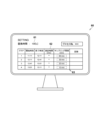
- FIG. 2 is a schematic diagram showing a display unit in the embodiment.
- 1A is a graph showing a change in particle diameter when the change in particle diameter over time gradually increases
- FIG. 1B is a graph showing a change in particle diameter when the absolute value of the particle diameter gradually increases, in a process of the particle diameter distribution measurement system in the embodiment.
- FIG. 2A is a schematic diagram showing the process of the particle size distribution measurement system in the embodiment
- FIG. 2B is a schematic diagram showing the process of a conventional particle size distribution measurement system.
- a particle size distribution measurement system 100 according to an embodiment of the present invention will be described below with reference to the drawings. Note that in any of the drawings shown below, some parts may be omitted or exaggerated in schematic form for ease of understanding. Identical components are given the same reference numerals and descriptions thereof will be omitted as appropriate.
- the particle size distribution measuring system 100 in this embodiment samples the generated sample from the generation flow path P through which the generated sample flows, in order to periodically observe the state of the generated sample, and measures the particle size distribution of the sample.
- the particle size distribution measurement system 100 includes a sample supply unit 10 that samples a sample and supplies the sample via a flow path 11, a pre-processing unit 20 that is provided in the flow path 11 and performs pre-processing of the sampled sample, a particle size distribution measurement unit 30 that measures the particle size distribution of the sample, an arithmetic and control device 40 that controls and performs calculations for the various devices that make up the particle size distribution measurement system 100, a process adjustment device 50 that adjusts the process of the particle size distribution measurement system 100, and a display unit 60 that displays various data.
- the configuration of each unit is described below.
- the sample supply unit 10 supplies a sample from the production flow path P to the particle size distribution measurement unit 30 via the flow path 11.
- the sample supply unit 10 has a flow path 11 that is connected to the production flow path P and the particle size distribution measurement unit 30 and through which the sample flows from the production flow path P to the particle size distribution measurement unit 30, a pump 12 that samples the sample from the production flow path P, and a sampling switching valve 13 that samples the sample from the production flow path P to the flow path 11 and closes the sampling.
- the flow path 11 has a sampling flow path 11a that connects the production flow path P and the pre-processing unit 20, and a post-pre-processing flow path 11b that connects the pre-processing unit 20 and the particle size distribution measurement unit 30.
- the sample supply unit 10 further includes a pump 14 that supplies the sample pretreated in the pretreatment unit 20 to the particle size distribution measurement unit 30, a mixer on-off valve 15 that opens and closes the discharge of liquid from the mixer 23 described below, and a flow cell on-off valve 16 that opens and closes the inflow of liquid to the flow cell 31 described below, but the pump 14, mixer on-off valve 15, and flow cell on-off valve 16 are not essential components.
- the pretreatment unit 20 dilutes the high-concentration sample when, for example, a high-concentration sample is sampled.
- the pretreatment unit 20 has a diluent storage unit 21 that stores diluent for diluting the sample, a diluent discharge pump 22 that draws out diluent from the diluent storage unit 21, a mixer 23 that mixes the diluent drawn out from the diluent discharge pump 22 and the sample sampled by the pump 12, a diluent discharge path 24 through which the diluent drawn out by the diluent discharge pump 22 flows, and a diluent discharge valve 25 that draws out the diluent from the diluent storage unit 21 to the diluent discharge path 24 and stops the drawing.
- the upstream side of the mixer 23 is connected to the diluent outlet path 24, through which the diluent discharged by the diluent discharge pump 22 flows, and the sampling flow path 11a, and the diluent and the sample are introduced into the mixer 23.
- the downstream side of the mixer 23 is connected to the post-pretreatment flow path 11b, and the sample after pretreatment is discharged from the mixer 23.
- the mixer 23 is, for example, a static mixer, but the mixer 23 is not limited to this and may be mixed by a tank, for example.
- the particle size distribution measuring unit 30 measures the particle size distribution of the sample diluted in the mixer 23.
- the particle size distribution measuring unit 30 includes a flow cell 31 through which the diluted sample flows, a light irradiating unit 32 that irradiates the sample in the flow cell 31 with light via lens R1, and a light detecting unit 33 that detects light diffracted or scattered from the sample via lens R2.
- the sample is discharged into the flow path 11 downstream of the flow cell 31.
- a flow cell outlet valve 34 is provided in the flow path 11 downstream of the flow cell 31, but the flow cell outlet valve 34 is not an essential component.
- the particle size distribution measuring unit 30 measures the particle size distribution when there is no sample flow in the flow cell 31, but it may also measure the particle size distribution when there is a sample flow in the flow cell 31.
- the light irradiating unit 32 is, for example, a laser light source, but is not limited to this.
- the light detecting unit 33 is, for example, a photomultiplier tube, but is not limited to this.
- the arithmetic and control device 40 is a general-purpose or dedicated computer equipped with a CPU, memory, etc. Specifically, the arithmetic and control device 40 functions as a particle size distribution calculation unit 41 that calculates the particle size distribution based on the light intensity signal obtained by the light detection unit 33, and as a control unit 42 that controls various devices that make up the particle size distribution measurement system 100, such as each pump, each valve, or the particle size distribution measurement unit 30, by the CPU and its peripheral devices working together in accordance with a program stored in a specified area of the memory.
- a particle size distribution calculation unit 41 that calculates the particle size distribution based on the light intensity signal obtained by the light detection unit 33
- control unit 42 that controls various devices that make up the particle size distribution measurement system 100, such as each pump, each valve, or the particle size distribution measurement unit 30, by the CPU and its peripheral devices working together in accordance with a program stored in a specified area of the memory.
- the process adjustment device 50 is a general-purpose or dedicated computer equipped with a CPU, memory, etc., and adjusts the process of the particle size distribution measurement system 100 by the CPU and its peripheral devices working together in accordance with a program stored in a specified area of the memory.
- the computer constituting the process adjustment device 50 may be a different computer from the computer constituting the arithmetic and control device 40, or it may be the same computer.
- the processes of the particle size distribution measurement system 100 include at least a sampling process for sampling a sample, a measurement process for measuring the particle size distribution of the sample, a cleaning process for cleaning at least one of the sample supply unit 10 and the particle size distribution measurement unit 30, and a standby process for waiting until the start of the next sampling process.
- the processes of the particle size distribution measurement system 100 proceed in the order of the sampling process, measurement process, cleaning process, and standby process.
- the process adjustment device 50 functions as a flow path information receiving unit 51 that acquires flow path information, which is information about the flow path 11; an arrival time calculation unit 52 that calculates an arrival time, which is the time from when the sample is sampled until it reaches the particle size distribution measurement unit 30; a sampling process time setting unit 53 that sets the sampling process time, which is the period during which the sample is sampled; a sampling interval receiving unit 54 that receives the sampling interval, which is the time from when a sampling process is started until when the next sampling process is started; and a process time adjustment unit 55 that adjusts the process time of the particle size distribution measurement system 100.
- the configuration of each unit of the process adjustment device 50 will be described below.
- the flow path information receiving unit 51 acquires flow path information input by a user.
- the flow path information is the pipe diameter of the pipe constituting the flow path 11, the flow path length of the flow path 11 from the connection point with the production flow path P to the connection point with the flow cell 31, the flow rate of the fluid measured by a flow sensor (not shown) provided in the flow path 11, the set value of the flow rate discharged by at least one of the pump 12, the pump 14, and the diluent discharge pump 22, the pipe diameter of the pipe constituting the diluent discharge path 24, the flow path length of the diluent discharge path 24, or device information indicating information of the device constituting the pre-processing unit 20.
- the device information of the pre-processing unit 20 is, for example, the device information of the mixer 23, and indicates the mixing time, which is the time from when the sample and diluent are introduced into the mixer 23 to when they are discharged. Note that, when the mixer 23 is a tank, the device information of the mixer 23 may be the mixing time required for the sample to reach a predetermined dilution ratio.
- the arrival time calculation unit 52 calculates the arrival time based on the flow path information acquired by the flow path information receiving unit 51.
- the arrival time here refers to the time it takes for the sampled sample to reach the measurement position, which is the position in the flow cell 31 where light from the light irradiation unit 32 is irradiated, from the connection point A between the generation flow path P and the flow path 11.
- the arrival time calculation unit 52 acquires the pipe diameter of the flow path 11 and the flow path length of the flow path 11 from the flow path information reception unit 51, and calculates the volume of the flow path 11. Then, the arrival time calculation unit 52 acquires the flow rate measured by the flow sensor and/or the set value of the flow rate discharged by at least one of the pump 12, the pump 14, and the diluent extraction pump 22 from the flow path information reception unit 51. Based on the volume of the flow path 11 and the measured flow rate, the arrival time calculation unit 52 calculates the time for the sample to reach the measurement position, which is the position in the flow cell 31 where the light from the light irradiation unit 32 is irradiated, from the connection point A between the generation flow path P and the flow path 11. Furthermore, the arrival time calculation unit 52 acquires device information of the mixer 23 from the flow path information reception unit 51. The arrival time calculation unit 52 calculates the arrival time using the time for the sample to reach the measurement position from the connection point A and the device information of the mixer 23.
- the arrival time calculation unit 52 further calculates the time from when the diluent is discharged until the diluent reaches the flow cell 31.
- the time calculated by the arrival time calculation unit 52 here is the time it takes for the diluent to reach the measurement position in the flow cell 31 from the outlet of the diluent storage unit 21.
- the arrival time calculation unit 52 acquires the pipe diameter of the diluent outlet path 24 and the flow path length of the diluent outlet path 24 from the flow path information reception unit 51, and calculates the volume of the diluent outlet path 24.
- the arrival time calculation unit 52 also acquires the pipe diameter of the post-pretreatment flow path 11b and the flow path length of the post-pretreatment flow path 11b from the flow path information reception unit 51, and calculates the volume of the post-pretreatment flow path 11b.
- the arrival time calculation unit 52 then acquires the flow rate measured by the flow sensor and the device information of the pretreatment unit 20 from the flow path information reception unit 51.
- the arrival time calculation unit 52 calculates the time from when the diluent is drawn out to when it reaches the flow cell 31, using the volume of the diluent outlet path 24, the volume of the post-pretreatment flow path 11b, the flow rate measured by the flow sensor, and the device information of the pretreatment unit 20.
- the sampling process time setting unit 53 sets the sampling process time based on the arrival time calculated by the arrival time calculation unit 52. Specifically, the sampling process time setting unit 53 sets the sampling process time to a time longer than the arrival time.
- the arrival time when setting the sampling process time is the total time of the time it takes for the sampled sample to reach the measurement position from connection point A and the device information of the mixer 23.
- the sampling process time refers to the time from when the pump 12 starts to operate until the sampled sample reaches the measurement position in the flow cell 31. More specifically, the sampling process time refers to (1) the time from when the sampling switch valve 13 and the diluent outlet valve 25 are opened and the pump 12 starts to operate until the sampled sample and diluent reach the measurement position in the flow cell 31 and the sampling switch valve 13 and the diluent outlet valve 25 are closed, or (2) the time from when the sampling switch valve 13 is opened and the pump 12 starts to operate until the sampled sample reaches the mixer 23, the sampling switch valve 13 is closed, the diluent outlet valve 25 is opened, the sampled sample and diluent reach the measurement position in the flow cell 31 and the diluent outlet valve 25 is closed. Note that in the sampling process time (2), the timing of opening the sampling switch valve 13 and the timing of opening the diluent outlet valve 25 may be the same.
- the sampling interval receiving unit 54 receives the sampling interval input by the user via the input means of the computer.
- the user can input any sampling interval.
- the process time adjustment unit 55 adjusts the process time of at least one of the sampling process, the measurement process, the cleaning process, or the waiting process when the sampling interval received by the sampling interval receiving unit 54 is equal to or less than a predetermined value.
- the measurement process time is specifically the time it takes for the light detection unit 33 to detect light diffracted or scattered from the sample, and is set in advance in the process adjustment device 50.
- the cleaning process time is the time it takes to clean the mixer 23, the post-pretreatment flow path 11b, and the flow cell 31, and is calculated by the arrival time calculation unit 52 and is the time it takes for the diluent to reach the flow cell 31.
- the cleaning process time may include the time it takes for the diluent to reach the flow cell 31, as well as the time it takes for the diluent to remove substances adhering to the inner surface of the flow cell 31 after the diluent reaches the flow cell 31.
- the process time adjustment unit 55 omits the cleaning process when the sampling interval received by the sampling interval reception unit 54 is equal to or less than a predetermined value. Specifically, when the sampling interval is equal to or less than a predetermined value, the process time adjustment unit 55 outputs a command signal to the control unit 42 to put the diluent discharge pump 22 into standby after the measurement process is completed.
- the process time adjustment unit 55 executes the cleaning process. Specifically, the process time adjustment unit 55 outputs a command signal to the control unit 42 to drive the diluent discharge pump 22 after the measurement process is completed.
- the specified value of the sampling interval is, for example, the time required from the start of the sampling process before adjustment to the end of the cleaning process before adjustment.
- the process time adjustment unit 55 acquires the sampling process time from the sampling process time setting unit 53. It also acquires the measurement process time that is set in advance in the process adjustment device 50. Furthermore, the process time adjustment unit 55 calculates the cleaning process time based on the time it takes for the dilution solution to reach the flow cell 31, which is calculated by the arrival time calculation unit 52. Then, the process time adjustment unit 55 adds up the sampling process time, measurement process time, and cleaning process time to calculate the specified value of the sampling interval.
- the display unit 60 is, for example, a display, and includes an arrival time display unit 61 that displays the arrival time calculated by the arrival time calculation unit 52, a measurement schedule display unit 62 that displays a measurement schedule, which is a schedule for measuring the sample, and a sampling interval input unit 63 where the user inputs the sampling interval. As shown in FIG. 3, the arrival time display unit 61, the measurement schedule display unit 62, and the sampling interval input unit 63 are provided on the same screen of the display.
- the measurement schedule display unit 62 displays the start time when sampling of the sample began, the end time when measurement of the particle size distribution ended, and the measurement time of the particle size distribution.
- the start time is the time when the user outputs a command signal to start driving the pump 12 to the control unit 42 via the input means of the computer.
- the measurement time of the particle size distribution is a time that is set in advance by the user or the computer. Note that the start time, end time, and measurement time may also be set by the user.
- the sampling interval input section 63 also displays the sampling interval input by the user via the computer's input means.
- the process of the particle size distribution measuring system 100 is a process in which the change in the particle size of the sample gradually increases.
- a set value of particle size is set for the sample flowing through the production flow path P.
- a sample with a particle size larger than the set value flows through the production flow path P, and the time change of the particle size gradually increases, and the particle size of the sample flowing through the production flow path P approaches the set value.
- S1, S2, S3, S4, S5, and S6 indicate the time when the sampling process is started, and the intervals between adjacent times indicate sampling intervals.
- the flow path information receiving unit 51 receives the flow path information.
- the arrival time calculation unit 52 acquires from the flow path information receiving unit 51, among the flow path information received by the flow path information receiving unit 51, the piping diameter of the flow path 11, the length of the flow path 11, the flow rate measured by the flow sensor, and the device information of the pre-processing unit 20. Then, the arrival time calculation unit 52 calculates the arrival time based on the flow path information acquired from the flow path information receiving unit 51.
- the arrival time display unit 61 displays the arrival time
- the measurement schedule display unit 62 displays the measurement time of the particle size distribution.
- the arrival time and the measurement time of the particle size distribution are displayed on the same screen of the display constituting the display unit 60.
- the sampling process time setting unit 53 also acquires the arrival time from the arrival time calculation unit 52 and sets the sampling process time to a time longer than the arrival time.
- the set sampling process time is output to the control unit 42.
- the user When the arrival time is displayed on the screen, the user inputs multiple sampling intervals into the sampling interval input unit 63 so that the sampling intervals become gradually shorter.
- the sampling interval receiving unit 54 receives the sampling intervals.
- the process time adjustment unit 55 determines whether the sampling interval is equal to or less than a predetermined value. If the sampling interval is equal to or less than the predetermined value, the process time adjustment unit 55 adjusts the process time of the particle size distribution measurement system 100 so as to omit the cleaning process. On the other hand, if the sampling interval is greater than the predetermined value, the process time adjustment unit 55 adjusts the process time of the particle size distribution measurement system 100 so as to perform the cleaning process.
- the user When the process time adjustment unit 55 has finished adjusting the process time of the particle size distribution measurement system 100, the user outputs a command signal to start the sampling process to the control unit 42 via the computer's input means. This drives the pump 12 and starts the sampling process. The time at which the user outputs the command signal to start the sampling process is displayed on the measurement schedule display unit 62.
- the control unit 42 controls the pump 12 based on the sampling process time, and the pump 12 samples the sample from the production flow path P.
- the particle size distribution measurement unit 30 measures the particle size distribution of the sample based on the measurement time displayed on the measurement schedule display unit 62.
- the cleaning process is skipped and the standby process is started.
- the cleaning process is started. Then, when the preset process time for the cleaning process ends, the standby process is started.
- the waiting process ends.
- the next sampling process begins, and the above-mentioned process of the particle size distribution measurement system 100 is repeated.
- the process of the particle size distribution measurement system 100 proceeds in the following order: sampling process, measurement process, cleaning process, and waiting process.
- the process time adjustment unit 55 omits the cleaning process.
- the process of the particle size distribution measurement system 100 proceeds in the order of the sampling process, the measurement process, and the standby process. As a result, even if a sampling interval equal to or less than a predetermined value is input, the process of the particle size distribution measurement system 100 can proceed.
- the cleaning process is not omitted, so the sampling interval needs to be greater than a predetermined value.
- the process time of the waiting process can only be shortened, because the process times of the sampling process, the measurement process, and the cleaning process are preset. Therefore, even if the user inputs a sampling interval that is less than the predetermined value, in the conventional example, the process of the particle size distribution measuring system 100 cannot proceed.
- the arrival time calculation unit 52 calculates the arrival time based on the flow path information, so that the arrival time is automatically calculated without the user having to perform complicated calculations. As a result, the burden on the user required to calculate the arrival time can be reduced, and the sampling process time can be easily calculated based on the arrival time calculated by the arrival time calculation unit 52.
- the arrival time calculation unit 52 calculates the arrival time by including the device information of the pretreatment unit 20 in the flow path information, so that the arrival time can be automatically calculated even for samples that require pretreatment, such as high-concentration samples.
- the arrival time display unit 61 and the measurement schedule display unit 62 are provided on the same screen, the user can see the arrival time and the measurement schedule at once.
- the display unit 60 of this embodiment can reduce the burden on the user when creating a measurement schedule based on the arrival time, compared to a configuration in which the arrival time and the measurement schedule are displayed on separate screens.
- sampling process time setting unit 53 sets a sampling process time that is longer than the arrival time, which can prevent the sample from being replaced in time within the flow path 11.
- the process time adjustment unit 55 adjusts the process time of at least one of the processes of the particle size distribution measurement system 100, so that the user can proceed with the process of the particle size distribution measurement system 100 even when the sampling interval is equal to or less than the predetermined value.
- the process time adjustment unit 55 adjusts the process time to be shorter, allowing the user to proceed with the process of the particle size distribution measurement system 100.
- the process time adjustment unit 55 omits the cleaning process when the sampling interval is equal to or less than a predetermined value, so that the next sampling process can be started earlier by the amount of the omitted cleaning process. As a result, even if the user inputs a sampling interval equal to or less than the predetermined value, the process of the particle size distribution measurement system 100 can proceed.
- the process time adjustment unit 55 can easily determine whether to omit the cleaning process based on the specified value of the sampling interval.
- the process adjustment device 50 In order for the process adjustment device 50 to calculate the arrival time, the process adjustment device 50 needs to have at least a flow path information receiving unit 51 and an arrival time calculation unit 52, and the sampling process time setting unit 53, the sampling interval receiving unit 54, and the process time adjustment unit 55 may be provided in a computer different from the process adjustment device 50. In addition, in order to calculate the arrival time, the particle size distribution measurement system 100 does not need to have a preprocessing unit 20 and a display unit 60.
- the arrival time calculation unit 52 calculates the arrival time by including the device information of the pre-processing unit 20 in the flow path information, but it may also calculate the arrival time without including the device information of the pre-processing unit 20 in the flow path information.
- the arrival time calculation unit 52 further calculates the time from when the diluent is drawn out until when the diluent reaches the flow cell 31, but it is not necessary to calculate the time from when the diluent is drawn out until when the diluent reaches the flow cell 31. In other words, the arrival time calculation unit 52 only needs to calculate at least the arrival time.
- the arrival time display unit 61 and the measurement schedule display unit 62 are provided on the same screen, but they may be provided on separate screens.
- the process time adjustment unit 55 omits the cleaning process when the sampling interval is equal to or less than a predetermined value, but it may also adjust other process times. Specifically, the process time adjustment unit 55 may shorten or omit the process time of the standby process when the sampling interval is equal to or less than a predetermined value. Alternatively, the process time adjustment unit 55 may adjust the process time of the sampling process by outputting a command signal to increase the output of the pump 12 to a drive circuit that drives the pump 12. Alternatively, the process time adjustment unit 55 may adjust the process time of the measurement process so that the particle size distribution measurement unit 30 measures the particle size distribution while the sample is flowing in the flow cell 31.
- the predetermined value of the sampling interval was the time required from the start of the pre-adjustment measurement process to the end of the pre-adjustment cleaning process, but is not limited to this.
- the predetermined value of the sampling interval may be set to any value by the user or computer.
- the process of the particle size distribution measurement system 100 is one in which the change in particle size of the sample flowing through the production flow path P gradually increases over time, but this is not limited to this.
- the process adjustment device 50 may adjust the process of the particle size distribution measurement system 100 in which the absolute value of the particle size of the sample gradually increases.
- the process adjustment device 50 is not limited to adjusting the process of the particle size distribution measurement system 100 in which the change in particle size of the sample gradually increases, but may also adjust the process of other particle size distribution measurement systems 100.
- the user inputs multiple sampling intervals into the sampling interval input unit 63 at once, but this is not limited to the above.
- the user may input the sampling interval in the next particle size distribution measurement schedule into the sampling interval input unit 63.
- the user may input a sampling interval that is shorter than the previous sampling interval into the sampling interval input unit 63.
- the process time adjustment unit 55 adjusts the process time when the sampling interval input to the sampling interval input unit 63 is equal to or less than a predetermined value, but this is not limited to this.
- the process time adjustment unit 55 may notify the user of an error on the display unit 60 when the sampling interval input to the sampling interval input unit 63 is equal to or less than a predetermined value.
- the sampling process time can be easily calculated.
Landscapes
- Chemical & Material Sciences (AREA)
- Life Sciences & Earth Sciences (AREA)
- General Health & Medical Sciences (AREA)
- Health & Medical Sciences (AREA)
- Analytical Chemistry (AREA)
- Biochemistry (AREA)
- Physics & Mathematics (AREA)
- General Physics & Mathematics (AREA)
- Immunology (AREA)
- Pathology (AREA)
- Dispersion Chemistry (AREA)
- Hydrology & Water Resources (AREA)
- Sampling And Sample Adjustment (AREA)
Abstract
粒子径分布測定システムは、試料の粒子径分布を測定する粒子径分布測定部と、前記試料をサンプリングするとともに、サンプリングされた前記試料が流れる流路を介して前記試料を前記粒子径分布測定部まで供給する試料供給部と、前記流路の情報である流路情報に基づいて、前記試料がサンプリングされてから前記粒子径分布測定部に到達するまでの時間である到達時間を算出する到達時間算出部とを備える。
Description
本発明は、粒子径分布測定システム、粒子径分布測定方法及び粒子径分布測定プログラムに関するものである。
従来、粒子径分布測定システムとしては、特許文献1に示すように、サンプリングした試料を希釈し、その希釈した試料の粒子径分布を測定するものがある。具体的にこのシステムでは、サンプリングした試料が流れる配管と、希釈液が流れる配管とがスタティックミキサ等の混合部に接続されており、その混合部で混合された液体がセンサに流れるように構成されている。そして、粒子径分布の測定が終了すると、希釈液により混合部及びその下流側が洗浄される。また、洗浄が終了した後に再び試料がサンプリングされて、粒子径分布が測定される。
ここで、サンプリング間隔が短くなると、試料をサンプリングするサンプリング工程の工程時間であるサンプリング工程時間が、試料がサンプリングされて粒子径分布を測定するセンサに到達するまでの時間である到達時間よりも短くなり、サンプリングされた試料がセンサに到達する前に、測定が開始されることになり、前にサンプリングされた試料と混合されてしまう等、所望の試料を測定できない。そのため、サンプリング工程時間は、到達時間よりも長く設定されている。
従来では、サンプリング工程時間を設定するために、ユーザが到達時間を算出している。しかしながら、ユーザが到達時間を算出する場合、ユーザは、流路の配管径、流路の長さ、流路の仕様又は流路を流れる試料の流量といった流路情報を用いて複雑な計算をする必要があった。このため、到達時間を算出するのにユーザの負担が生じており、サンプリング工程時間を算出するのに時間を要していた。
そこで、本発明は上述したような問題に鑑みてなされたものであり、サンプリングされた試料が粒子径分布を測定する箇所まで流路を介して供給される粒子径分布測定システムにおいて、サンプリング工程時間を簡単に算出することをその主たる課題とするものである。
すなわち、本発明に係る粒子径分布測定システムは、試料の粒子径分布を測定する粒子径分布測定部と、前記試料をサンプリングするとともに、サンプリングされた前記試料が流れる流路を介して前記試料を前記粒子径分布測定部まで供給する試料供給部と、前記流路の情報である流路情報に基づいて、前記試料がサンプリングされてから前記粒子径分布測定部に到達するまでの時間である到達時間を算出する到達時間算出部とを備えることを特徴とする。
このような粒子径分布測定システムであれば、到達時間算出部が流路情報に基づいて到達時間を算出するので、ユーザが複雑な計算をすることなく、到達時間が自動的に算出される。その結果、到達時間を算出するのに要するユーザの負担を軽減することができるとともに、到達時間算出部により算出された到達時間に基づいて、サンプリング工程時間を簡単に算出することができる。
到達時間をより正確に算出するためには、前記流路情報は、前記流路を構成する配管の配管径、前記流路の長さである流路長及び前記流路を流れる前記試料の流量の少なくとも一つであることが望ましい。
ここで、例えば試料の濃度が高い場合、試料の粒子径分布を精度よく測定するために試料が前処理される場合がある。この場合、試料がサンプリングされてから測定されるまでの間に試料が前処理されるので、試料の前処理の分だけ到達時間が長くなる。
そこで、前記粒子径分布測定システムは、前記流路に設けられるとともに、サンプリングされた前記試料の前処理を行う前処理部をさらに備え、前記到達時間算出部は、前記前処理部を構成する装置の情報である装置情報を前記流路情報に含めて前記到達時間を算出するものが挙げられる。
そこで、前記粒子径分布測定システムは、前記流路に設けられるとともに、サンプリングされた前記試料の前処理を行う前処理部をさらに備え、前記到達時間算出部は、前記前処理部を構成する装置の情報である装置情報を前記流路情報に含めて前記到達時間を算出するものが挙げられる。
このような構成であれば、到達時間算出部は、前処理部の装置情報を流路情報に含めて到達時間を算出するので、例えば高濃度試料といった前処理を必要とする試料をサンプリングする場合でも、到達時間を自動的に算出することができる。
前記到達時間算出部により算出された前記到達時間を表示する到達時間表示部と、前記試料の測定のスケジュールである測定スケジュールを表示する測定スケジュール表示部とをさらに備え、前記到達時間表示部及び前記測定スケジュール表示部は同じ画面に設けられるものが好ましい。
このような構成であれば、到達時間及び測定スケジュールが同じ画面に表示されるので、ユーザは到達時間及び測定スケジュールを一度に見ることができる。その結果、到達時間及び測定スケジュールが別々の画面に表示される構成と比較して、到達時間に基づいて測定スケジュールを作成する際のユーザの負担を軽減することができる。
前記粒子径分布測定システムは、前記到達時間算出部により算出された前記到達時間に基づいて、前記試料をサンプリングするサンプリング工程時間を設定するサンプリング工程時間設定部をさらに備え、前記サンプリング工程時間設定部は、前記サンプリング工程時間を前記到達時間よりも長い時間とすることが望ましい。
このような構成であれば、サンプリング工程時間設定部は、サンプリング工程時間を到達時間よりも長く設定するので、流路内における試料の置換が間に合わない事態を防ぐことができる。また、サンプリング工程時間の下限値は到達時間であるので、到達時間算出部により、サンプリング工程時間の下限値を自動的に算出することができる。
前記粒子径分布測定システムは、前記粒子径分布測定システムの工程を調整する工程調整装置をさらに備え、前記工程調整装置は、前記試料をサンプリングするサンプリング工程が開始されてから次の前記サンプリング工程が開始されるまでの時間であるサンプリング間隔を受け付けるサンプリング間隔受付部と、前記サンプリング間隔受付部が受け付けた前記サンプリング間隔が所定値以下である場合に、前記サンプリング工程、前記試料の前記粒子径分布を測定する測定工程、前記粒子径分布測定部及び前記試料供給部の少なくとも一つを洗浄する洗浄工程、又は、次の前記サンプリング工程の開始まで待機する待機工程のうち少なくとも一つの工程時間を調整する工程時間調整部とを備えるものが挙げられる。
このような構成であれば、サンプリング間隔が所定値以下である場合に、工程時間調整部が粒子径分布測定システムの工程のうち少なくとも一つの工程時間を調整するので、所定値以下のサンプリング間隔でも粒子径分布測定システムの工程を進行させることができる。その結果、例えば試料の状態が早く変化する粒子径分布測定システムの工程においても、工程時間調整部が工程時間を短く調整することによって、粒子径分布測定システムは、試料の状態の変化に追従して粒子径分布を測定することができる。
前記工程時間調整部は、前記サンプリング間隔受付部が受け付けた前記サンプリング間隔が所定値以下である場合に、前記洗浄工程を省略するものが好ましい。
このような構成であれば、工程時間調整部は、サンプリング間隔が所定値以下である場合に、洗浄工程を省略するので、省略された洗浄工程の分だけサンプリング間隔を短くすることができる。
前記サンプリング間隔の所定値は、調整前の前記測定工程の開始から調整前の前記洗浄工程の終了までに要する時間であるものが挙げられる。
このような構成であれば、サンプリング間隔の所定値は、調整前の測定工程の開始から調整前の洗浄工程の終了までに要する時間であるので、サンプリング間隔が所定値以下である場合には、洗浄工程を行うための十分な時間がないことを示す。その結果、工程時間調整部は、サンプリング間隔の所定値に基づいて洗浄工程を省略するかどうかを簡単に判断することができる。
粒子径分布測定システムでは、サンプリングされる試料の例えば粒子径の設定値が与えられる場合がある。この場合、試料の粒子径が設定値に漸近するにつれて試料の粒子径変化が小さくなるので、サンプリング間隔を徐々に短くすることによって、試料の粒子径分布を測定する必要がある。
そのため、前記工程調整装置は、前記サンプリング間隔が徐々に短くなる前記粒子径分布測定システムの工程を調整することが好適である。
そのため、前記工程調整装置は、前記サンプリング間隔が徐々に短くなる前記粒子径分布測定システムの工程を調整することが好適である。
粒子径分布測定システムにおいて、例えば試料の粒子径の絶対値や単位時間当たりの粒子径の変化幅といった試料の粒子径の変化が徐々に大きくなる場合、その粒子径の変化に追従するためにサンプリング間隔が徐々に短くなる。
そのため、前記工程調整装置は、前記試料の粒子径の変化が徐々に大きくなる前記粒子径分布測定システムの工程を調整することが好適である。
そのため、前記工程調整装置は、前記試料の粒子径の変化が徐々に大きくなる前記粒子径分布測定システムの工程を調整することが好適である。
試料の粒子径分布を測定する粒子径分布測定部を用いる粒子径分布測定方法は、前記試料をサンプリングするとともに、サンプリングされた前記試料が流れる流路を介して前記試料を前記粒子径分布測定部まで供給し、前記流路の情報である流路情報に基づいて、前記試料がサンプリングされてから前記粒子径分布測定部に到達するまでの時間である到達時間を算出するものが挙げられる。
このような構成であれば、上記の粒子径分布測定システムと同様の作用効果を得ることができる。
試料の粒子径分布を測定する粒子径分布測定部と、前記試料をサンプリングするとともに、サンプリングされた前記試料が流れる流路を介して前記試料を前記粒子径分布測定部まで供給する試料供給部とを備える粒子径分布測定システムに用いられる粒子径分布測定プログラムは、前記流路の情報である流路情報に基づいて、前記試料がサンプリングされてから前記粒子径分布測定部に到達するまでの時間である到達時間を算出する到達時間算出部としての機能をコンピュータに発揮させることを特徴とする。
このような構成であれば、上記の粒子径分布測定システムと同様の作用効果を得ることができる。
このように構成した本発明によれば、サンプリングされた試料が粒子径分布を測定する箇所まで流路を介して供給される粒子径分布測定システムにおいて、サンプリング工程時間を簡単に算出することができる。
<本実施形態>
以下に、本発明の一実施形態に係る粒子径分布測定システム100について、図面を参照して説明する。なお、以下に示す何れの図についても、わかりやすくするために、適宜省略し又は誇張して模式的に描かれている場合がある。同一の構成要素については、同一の符号を付して説明を適宜省略する。
以下に、本発明の一実施形態に係る粒子径分布測定システム100について、図面を参照して説明する。なお、以下に示す何れの図についても、わかりやすくするために、適宜省略し又は誇張して模式的に描かれている場合がある。同一の構成要素については、同一の符号を付して説明を適宜省略する。
<粒子径分布測定システム>
本実施形態における粒子径分布測定システム100は、生成された試料の状態を定期的に観察するために、生成された試料が流れている生成流路Pから当該試料をサンプリングして、当該試料の粒子径分布を測定するものである。
本実施形態における粒子径分布測定システム100は、生成された試料の状態を定期的に観察するために、生成された試料が流れている生成流路Pから当該試料をサンプリングして、当該試料の粒子径分布を測定するものである。
具体的に粒子径分布測定システム100は、試料をサンプリングするとともに、流路11を介して試料を供給する試料供給部10と、流路11に設けられ、サンプリングされた試料の前処理を行う前処理部20と、試料の粒子径分布を測定する粒子径分布測定部30と、粒子径分布測定システム100を構成する各種機器の制御及び演算を行う演算制御装置40と、粒子径分布測定システム100の工程を調整する工程調整装置50と、各種データを表示する表示部60とを備える。以下、各部の構成について説明する。
試料供給部10は、流路11を介して、生成流路Pから粒子径分布測定部30へと試料を供給するものである。具体的に試料供給部10は、生成流路P及び粒子径分布測定部30に接続され、生成流路Pから粒子径分布測定部30まで試料が流れる流路11と、生成流路Pから試料をサンプリングするポンプ12と、生成流路Pから流路11への試料のサンプリング及び当該サンプリングの閉止を行うサンプリング切替弁13を有する。本実施形態において、流路11は、生成流路P及び前処理部20を接続するサンプリング流路11aと、前処理部20及び粒子径分布測定部30を接続する前処理後流路11bとを有する。なお、本実施形態では、試料供給部10は、前処理部20で前処理された試料を粒子径分布測定部30まで供給するポンプ14と、後述する混合器23から液体の導出を開閉する混合器開閉弁15と、後述するフローセル31への液体の流入を開閉するフローセル開閉弁16とをさらに有するが、ポンプ14、混合器開閉弁15及びフローセル開閉弁16は必須の構成ではない。
前処理部20は、例えば試料の濃度が高い高濃度試料がサンプリングされた場合に、当該高濃度試料を希釈するものである。具体的に前処理部20は、試料を希釈する希釈液を貯留する希釈液貯留部21と、希釈液貯留部21から希釈液を導出する希釈液導出ポンプ22と、希釈液導出ポンプ22から導出された希釈液及びポンプ12によりサンプリングされた試料を混合する混合器23と、希釈液導出ポンプ22により導出された希釈液が流れる希釈液導出路24と、希釈液貯留部21から希釈液導出路24への希釈液の導出及び当該導出の停止を行う希釈液導出弁25を有する。
混合器23の上流側は、希釈液導出ポンプ22により導出された希釈液が流れる希釈液導出路24及びサンプリング流路11aに接続されており、希釈液及びサンプリングされた試料が混合器23に導入される。また、混合器23の下流側は、前処理後流路11bに接続されており、前処理された後の試料が混合器23から導出される。なお、本実施形態において、混合器23は、例えばスタティックミキサであるが、混合器23はこれに限られず、例えばタンクにより混合してもよい。
粒子径分布測定部30は、混合器23で希釈された試料の粒子径分布を測定するものである。具体的に粒子径分布測定部30は、希釈された試料が流れるフローセル31と、フローセル31内の試料にレンズR1を介して光を照射する光照射部32と、試料から回折又は散乱した光をレンズR2を介して検出する光検出部33とを備える。なお、粒子径分布の測定が終了した後の試料は、フローセル31の下流側の流路11に排出される。フローセル31の下流側の流路11には、フローセル出口弁34が設けられているが、フローセル出口弁34は必須の構成ではない。
本実施形態において、粒子径分布測定部30は、フローセル31内に試料の流れがない状態で粒子径分布を測定するものであるが、フローセル31内で試料の流れがある状態で粒子径分布を測定するものであってもよい。なお、本実施形態において、光照射部32は例えばレーザ光源であるがこれに限られない。また、光検出部33は例えば光電子増倍管であるがこれに限られない。
演算制御装置40は、CPU、メモリなどを備えた汎用乃至専用のコンピュータである。具体的に演算制御装置40は、メモリの所定領域に格納したプログラムに従ってCPUやその周辺機器が協働することによって、光検出部33により得られた光強度信号に基づいて粒子径分布を算出する粒子径分布算出部41として機能と、各ポンプ、各バルブ又は粒子径分布測定部30といった粒子径分布測定システム100を構成する各種機器を制御する制御部42としての機能を発揮する。
工程調整装置50は、CPU、メモリなどを備えた汎用乃至専用のコンピュータであり、メモリの所定領域に格納したプログラムに従ってCPUやその周辺機器が協働することによって、粒子径分布測定システム100の工程を調整するものである。なお、工程調整装置50を構成するコンピュータは、演算制御装置40を構成するコンピュータとは別のコンピュータであってもよいし、同一のコンピュータであってもよい。
ここで、粒子径分布測定システム100の工程とは、試料をサンプリングするサンプリング工程、試料の粒子径分布を測定する測定工程、試料供給部10及び粒子径分布測定部30の少なくとも一つを洗浄する洗浄工程、及び、次のサンプリング工程の開始まで待機する待機工程を少なくとも含むものである。本実施形態において、粒子径分布測定システム100の工程は、サンプリング工程、測定工程、洗浄工程及び待機工程の順で進められる。
具体的に工程調整装置50は、流路11の情報である流路情報を取得する流路情報受付部51と、試料がサンプリングされてから粒子径分布測定部30に到達するまでの時間である到達時間を算出する到達時間算出部52と、試料をサンプリングする期間であるサンプリング工程時間を設定するサンプリング工程時間設定部53と、サンプリング工程が開始されてから次のサンプリング工程が開始されるまでの時間であるサンプリング間隔を受け付けるサンプリング間隔受付部54と、粒子径分布測定システム100の工程時間を調整する工程時間調整部55としての機能を発揮する。以下、工程調整装置50の各部の構成について説明する。
流路情報受付部51は、ユーザにより入力された流路情報を取得するものである。本実施形態において、流路情報は、流路11を構成する配管の配管径、生成流路Pとの接続箇所からフローセル31との接続箇所までの流路11の流路長、流路11に設けられた流量センサ(不図示)により測定された流体の流量、ポンプ12、ポンプ14及び希釈液導出ポンプ22の少なくとも一つが吐出する流量の設定値、希釈液導出路24を構成する配管の配管径、希釈液導出路24の流路長又は前処理部20を構成する装置の情報を示す装置情報である。前処理部20の装置情報は、例えば混合器23の装置情報であり、ここでは、試料及び希釈液が混合器23に導入されてから導出されるまでの時間である混合時間を示す。なお、混合器23がタンクである場合、混合器23の装置情報は、試料が所定の希釈率に達するまでに要する混合時間であってもよい。
到達時間算出部52は、流路情報受付部51が取得した流路情報に基づいて到達時間を算出するものである。ここで言う到達時間とは、生成流路Pと流路11との接続点Aから光照射部32からの光が照射されているフローセル31内の位置である測定位置までをサンプリングされた試料が到達する時間のことを言う。
具体的に到達時間算出部52は、流路情報受付部51から流路11の配管径及び流路11の流路長を取得して、流路11の容積を算出する。そして、到達時間算出部52は、流量センサにより測定された流量及び/又はポンプ12、ポンプ14及び希釈液導出ポンプ22の少なくとも一つが吐出する流量の設定値を流路情報受付部51から取得する。到達時間算出部52は、流路11の容積及び測定された流量に基づいて、生成流路Pと流路11との接続点Aから光照射部32からの光が照射されているフローセル31内の位置である測定位置までに試料が到達する時間を算出する。さらに、到達時間算出部52は、流路情報受付部51から混合器23の装置情報を取得する。到達時間算出部52は、試料が接続点Aから測定位置までに到達する時間及び混合器23の装置情報を用いて到達時間を算出する。
本実施形態において、到達時間算出部52は、希釈液が導出されてから希釈液がフローセル31に到達するまでの時間をさらに算出する。ここで到達時間算出部52が算出する時間は、希釈液貯留部21の導出口からフローセル31内の測定位置までに希釈液が到達する時間である。
より詳細には、到達時間算出部52は、流路情報受付部51から希釈液導出路24の配管径及び希釈液導出路24の流路長を取得して、希釈液導出路24の容積を算出する。また、到達時間算出部52は、流路情報受付部51から前処理後流路11bの配管径及び前処理後流路11bの流路長を取得して、前処理後流路11bの容積を算出する。そして、到達時間算出部52は、流路情報受付部51から流量センサにより測定された流量及び前処理部20の装置情報を取得する。到達時間算出部52は、希釈液導出路24の容積、前処理後流路11bの容積、流量センサにより測定された流量及び前処理部20の装置情報を用いて、希釈液が導出されてからフローセル31に到達するまでの時間を算出する。
サンプリング工程時間設定部53は、到達時間算出部52により算出された到達時間に基づいて、サンプリング工程時間を設定するものである。具体的にサンプリング工程時間設定部53は、サンプリング工程時間を到達時間よりも長い時間に設定する。ここで、サンプリング工程時間を設定する際の到達時間とは、サンプリングされた試料が接続点Aから測定位置までに到達する時間及び混合器23の装置情報の合計時間である。
本実施形態において、サンプリング工程時間とは、ポンプ12の駆動が開始してからサンプリングされた試料がフローセル31の測定位置に到達するまでの時間をいう。より詳細にはサンプリング工程時間とは、(1)サンプリング切替弁13及び希釈液導出弁25が開放されてからポンプ12の駆動が開始された後、サンプリングされた試料及び希釈液がフローセル31内の測定位置まで到達して、サンプリング切替弁13及び希釈液導出弁25が閉止するまでの時間、又は、(2)サンプリング切替弁13が開放されてからポンプ12の駆動が開始された後、サンプリングされた試料が混合器23に到達してサンプリング切替弁13を閉止するとともに希釈液導出弁25を開放し、サンプリングされた試料及び希釈液がフローセル31内の測定位置まで到達して希釈液導出弁25が閉止されるまでの時間である。なお、(2)のサンプリング工程時間において、サンプリング切替弁13の開放のタイミングと希釈液導出弁25の開放タイミングは同じであってもよい。
サンプリング間隔受付部54は、ユーザがコンピュータの入力手段を介して入力したサンプリング間隔を受け付けるものである。本実施形態において、ユーザは、任意のサンプリング間隔を入力することができる。
工程時間調整部55は、サンプリング間隔受付部54が受け付けたサンプリング間隔が所定値以下である場合に、サンプリング工程、測定工程、洗浄工程又は待機工程のうちの少なくとも一つの工程時間を調整するものである。ここで、測定工程時間とは、具体的には光検出部33が試料から回折又は散乱した光を検出する時間であり、予め工程調整装置50に設定されている。さらに、洗浄工程時間とは、混合器23、前処理後流路11b及びフローセル31を洗浄する時間であり、到達時間算出部52によって算出され、希釈液がフローセル31に到達するまでの時間である。なお、洗浄工程時間には、希釈液がフローセル31に到達するまでの時間に加えて、希釈液がフローセル31に到達した後、希釈液によりフローセル31の内面に付着した物質を落とす時間を含めてもよい。
本実施形態において、工程時間調整部55は、サンプリング間隔受付部54が受け付けたサンプリング間隔が所定値以下である場合に、洗浄工程を省略する。具体的に工程時間調整部55は、サンプリング間隔が所定値以下である場合に、測定工程の終了後に希釈液導出ポンプ22を待機させる指令信号を制御部42に出力する。
一方、工程時間調整部55は、サンプリング間隔が所定値よりも大きい場合、洗浄工程を実行する。具体的に工程時間調整部55は、測定工程の終了後に希釈液導出ポンプ22を駆動させる指令信号を制御部42に出力する。
本実施形態において、サンプリング間隔の所定値とは、例えば調整前のサンプリング工程の開始から調整前の洗浄工程の終了までに要する時間である。ここで工程時間調整部55は、サンプリング工程時間設定部53からサンプリング工程時間を取得する。また、工程調整装置50に予め設定された測定工程時間を取得する。さらに、工程時間調整部55は、到達時間算出部52によって算出され、希釈液がフローセル31に到達するまでの時間に基づいて、洗浄工程時間を算出する。そして、工程時間調整部55は、サンプリング工程時間、測定工程時間及び洗浄工程時間を加算して、サンプリング間隔の所定値を算出する。
表示部60は、例えばディスプレイであり、到達時間算出部52により算出された到達時間を表示する到達時間表示部61と、試料の測定のスケジュールである測定スケジュールを表示する測定スケジュール表示部62と、ユーザがサンプリング間隔を入力するサンプリング間隔入力部63とを備える。図3に示すように、到達時間表示部61、測定スケジュール表示部62及びサンプリング間隔入力部63は、ディスプレイの同一画面に設けられる。
本実施形態において、測定スケジュール表示部62は、試料のサンプリングを開始した開始時刻、粒子径分布の測定を終了した終了時刻及び粒子径分布の測定時間、を表示する。ここで、開始時刻は、ポンプ12の駆動を開始する指令信号をユーザがコンピュータの入力手段を介して制御部42に出力した時刻である。粒子径分布の測定時間は、予めユーザ又はコンピュータによって設定された時間である。なお、開始時刻、終了時間及び測定時間は、ユーザにより設定されるものであってもよい。
また、サンプリング間隔入力部63には、コンピュータの入力手段によってユーザが入力したサンプリング間隔が表示される。
<粒子径分布測定方法>
次に本実施形態の粒子径分布測定システム100を用いた粒子径分布測定方法について説明する。本実施形態において、粒子径分布測定システム100の工程は、試料の粒子径の変化が徐々に大きくなる工程である。具体的には、図4(a)に示すように、粒子径分布測定システム100の工程では、生成流路Pを流れる試料に粒子径の設定値が設定されている。そして、生成流路Pには設定値よりも大きい粒子径の試料が流れており、粒子径の時間変化が徐々に大きくなって、生成流路Pを流れる試料の粒子径は設定値に漸近する。また、図4(a)において、S1、S2、S3、S4、S5及びS6はサンプリング工程が開始される時刻を示しており、隣り合う各時刻の間はサンプリング間隔を示す。
次に本実施形態の粒子径分布測定システム100を用いた粒子径分布測定方法について説明する。本実施形態において、粒子径分布測定システム100の工程は、試料の粒子径の変化が徐々に大きくなる工程である。具体的には、図4(a)に示すように、粒子径分布測定システム100の工程では、生成流路Pを流れる試料に粒子径の設定値が設定されている。そして、生成流路Pには設定値よりも大きい粒子径の試料が流れており、粒子径の時間変化が徐々に大きくなって、生成流路Pを流れる試料の粒子径は設定値に漸近する。また、図4(a)において、S1、S2、S3、S4、S5及びS6はサンプリング工程が開始される時刻を示しており、隣り合う各時刻の間はサンプリング間隔を示す。
ユーザがコンピュータの入力手段を介して流路情報を入力すると、流路情報受付部51は、流路情報を受け付ける。
到達時間算出部52は、流路情報受付部51が受け付けた流路情報のうち、流路情報受付部51から流路11の配管径、流路11の長さ、流量センサにより測定された流量及び前処理部20の装置情報を取得する。そして、到達時間算出部52は、流路情報受付部51から取得した流路情報に基づいて到達時間を算出する。
到達時間が算出されると、到達時間表示部61は、到達時間を表示するとともに、測定スケジュール表示部62は、粒子径分布の測定時間を表示する。その結果、表示部60を構成するディスプレイの同一画面には、到達時間及び粒子径分布の測定時間が表示される。
また、サンプリング工程時間設定部53は、到達時間算出部52から到達時間を取得して、サンプリング工程時間を到達時間よりも長い時間に設定する。設定されたサンプリング工程時間は制御部42に出力される。
到達時間が画面に表示されると、ユーザは、サンプリング間隔が徐々に短くなるように、複数のサンプリング間隔をサンプリング間隔入力部63へ入力する。ユーザがサンプリング間隔を入力すると、サンプリング間隔受付部54は、サンプリング間隔を受け付ける。
次に、工程時間調整部55は、サンプリング間隔が所定値以下であるかどうかを判断する。サンプリング間隔が所定値以下である場合、工程時間調整部55は、洗浄工程を省略するように、粒子径分布測定システム100の工程時間を調整する。一方、サンプリング間隔が所定値よりも大きい場合、工程時間調整部55は、洗浄工程を行うように、粒子径分布測定システム100の工程時間を調整する。
工程時間調整部55が粒子径分布測定システム100の工程時間の調整を終えると、ユーザは、サンプリング工程を開始する指令信号を制御部42にコンピュータの入力手段を介して出力する。これにより、ポンプ12が駆動してサンプリング工程が開始される。ユーザがサンプリング工程を開始する指令信号を出力した時刻は、測定スケジュール表示部62に表示される。
制御部42がサンプリング工程時間に基づいてポンプ12を制御することより、ポンプ12は、生成流路Pから試料をサンプリングする。サンプリング工程時間が終了すると、粒子径分布測定部30は、測定スケジュール表示部62に表示された測定時間に基づいて、試料の粒子径分布を測定する。
測定時間が終了してサンプリング間隔が所定値以下である場合には、洗浄工程が省略され、待機工程が開始される。
一方、測定時間が終了してサンプリング間隔が所定値よりも大きい場合には、洗浄工程が開始される。そして、予め設定された洗浄工程の工程時間が終了すると、待機工程が開始される。
ユーザが入力したサンプリング間隔の時間が終了すると、待機工程が終了する。待機工程が終了すると、次のサンプリング工程が開始され、上記の粒子径分布測定システム100の工程が繰り返される。
<実施例>
次に本実施形態の工程調整装置50を用いた実施例における工程調整と従来例における工程調整との比較を、図5を参照しつつ説明する。なお、実施例及び従来例ともに、サンプリング工程の工程時間、測定工程の工程時間及び洗浄工程の工程時間は、予め設定されている。
次に本実施形態の工程調整装置50を用いた実施例における工程調整と従来例における工程調整との比較を、図5を参照しつつ説明する。なお、実施例及び従来例ともに、サンプリング工程の工程時間、測定工程の工程時間及び洗浄工程の工程時間は、予め設定されている。
図5(a)に示すように、ユーザが、所定値よりも大きいサンプリング間隔を入力すると、粒子径分布測定システム100の工程は、サンプリング工程、測定工程、洗浄工程及び待機工程の順に進行する。
そして、図5(a)に示すように、ユーザが、所定値以下のサンプリング間隔を入力すると、工程時間調整部55は、洗浄工程を省略する。その結果、粒子径分布測定システム100の工程は、サンプリング工程、測定工程及び待機工程の順に進行する。その結果、所定値以下のサンプリング間隔が入力される場合でも、粒子径分布測定システム100の工程を進行させることができる。
一方、図5(b)に示すように、従来例では、洗浄工程が省略されないので、サンプリング間隔は所定値よりも大きくする必要がある。そして、従来例では、前に入力されたサンプリング間隔よりも短いサンプリング間隔が入力されると、サンプリング工程の工程時間、測定工程の工程時間及び洗浄工程の工程時間は予め設定されているので、待機工程の工程時間を短くすることしかできない。従って、ユーザが所定値以下のサンプリング間隔を入力したとしても、従来例では、粒子径分布測定システム100の工程を進行することができない。
<本実施形態の効果>
本実施形態における粒子径分布測定システム100によれば、到達時間算出部52が流路情報に基づいて到達時間を算出するので、ユーザが複雑な計算をすることなく、到達時間が自動的に算出される。その結果、到達時間を算出するのに要するユーザの負担を軽減することができるとともに、到達時間算出部52により算出された到達時間に基づいて、サンプリング工程時間を簡単に算出することができる。
本実施形態における粒子径分布測定システム100によれば、到達時間算出部52が流路情報に基づいて到達時間を算出するので、ユーザが複雑な計算をすることなく、到達時間が自動的に算出される。その結果、到達時間を算出するのに要するユーザの負担を軽減することができるとともに、到達時間算出部52により算出された到達時間に基づいて、サンプリング工程時間を簡単に算出することができる。
また、到達時間算出部52が、前処理部20の装置情報を流路情報に含めて到達時間を算出するので、例えば高濃度試料といった前処理を必要とする試料においても、到達時間を自動的に算出することができる。
さらに、到達時間表示部61及び測定スケジュール表示部62が同じ画面に設けられるので、ユーザは到達時間及び測定スケジュールを一度に見ることができる。その結果、本実施形態の表示部60は、到達時間及び測定スケジュールが別々の画面に表示される構成と比較して、到達時間に基づいて測定スケジュールを作成する際のユーザの負担を軽減することができる。
加えて、サンプリング工程時間設定部53は、到達時間よりも長いサンプリング工程時間を設定するので、流路11内で試料の置換が間に合わない事態を防ぐことができる。
その上、サンプリング間隔が所定値以下である場合に、工程時間調整部55が粒子径分布測定システム100の工程のうち少なくとも一つの工程時間を調整するので、ユーザは、所定値以下のサンプリング間隔でも粒子径分布測定システム100の工程を進行することができる。その結果、例えば試料の状態が早く変化するプロセスにおいても、工程時間調整部55が工程時間を短く調整することによって、ユーザは、粒子径分布測定システム100の工程を進行させることができる。
本実施形態において、工程時間調整部55は、サンプリング間隔が所定値以下である場合に、洗浄工程を省略するので、省略された洗浄工程の分だけ次のサンプリング工程を早く開始することができる。その結果、ユーザが、所定値以下のサンプリング間隔を入力する場合でも、粒子径分布測定システム100の工程を進行させることができる。
また、サンプリング間隔の所定値は、調整前の測定工程の開始から調整前の洗浄工程の終了までに要する時間であるので、サンプリング間隔が所定値以下である場合には、洗浄工程を行うための十分な時間がないことを示す。その結果、工程時間調整部55は、サンプリング間隔の所定値に基づいて洗浄工程を省略するかどうかを簡単に判断することができる。
<その他の実施形態>
なお、本発明は、前記実施形態に限られるものではない。
なお、本発明は、前記実施形態に限られるものではない。
工程調整装置50が到達時間を算出するためには、工程調整装置50は、流路情報受付部51と、到達時間算出部52とを少なくとも備えればよく、サンプリング工程時間設定部53、サンプリング間隔受付部54及び工程時間調整部55は、工程調整装置50とは異なるコンピュータに設けられていてもよい。また、到達時間を算出するためには、粒子径分布測定システム100は、前処理部20及び表示部60を備えていなくともよい。
前記実施形態において、到達時間算出部52は、前処理部20の装置情報を流路情報に含めて到達時間を算出するものであったが、前処理部20の装置情報を流路情報に含めずに到達時間を算出するものであってもよい。
前記実施形態において、到達時間算出部52は、希釈液が導出されてから希釈液がフローセル31に到達するまでの時間をさらに算出するものであったが、希釈液が導出されてから希釈液がフローセル31に到達するまでの時間を算出しなくてもよい。すなわち、到達時間算出部52は、少なくとも到達時間を算出すればよい。
前記実施形態において、到達時間表示部61及び測定スケジュール表示部62は、同じ画面に設けられるものであったが、別々の画面に設けられるものであってもよい。
前記実施形態において、工程時間調整部55は、サンプリング間隔が所定値以下である場合に、洗浄工程を省略するものであったが、他の工程時間を調整するものであってもよい。具体的に工程時間調整部55は、サンプリング間隔が所定値以下である場合に、待機工程の工程時間を短縮又は省略するものであってもよい。又は、工程時間調整部55は、ポンプ12の出力を増大させる指令信号を、ポンプ12を駆動させる駆動回路に出力して、サンプリング工程の工程時間を調整してもよい。又は、工程時間調整部55は、フローセル31内に試料が流れている状態で粒子径分布測定部30が粒子径分布を測定するように、測定工程の工程時間を調整してもよい。
前記実施形態において、サンプリング間隔の所定値は、調整前の測定工程の開始から調整前の洗浄工程の終了までに要する時間であったが、これに限られない。サンプリング間隔の所定値は、ユーザ又はコンピュータによって任意の値に設定されてもよい。
前記実施形態において、粒子径分布測定システム100の工程は、生成流路Pを流れる試料の粒子径の時間変化が徐々に大きくなるものであったが、これに限られない。例えば、図4(b)に示すように、工程調整装置50は、試料の粒子径の絶対値が徐々に大きくなる粒子径分布測定システム100の工程を調整してもよい。なお、工程調整装置50は、試料の粒子径の変化が徐々に大きくなる粒子径分布測定システム100の工程を調整するものに限られず、その他の粒子径分布測定システム100の工程を調整するものであってもよい。
前記実施形態において、ユーザは複数のサンプリング間隔を一度にサンプリング間隔入力部63に入力するものであったがこれに限られない。例えば、待機工程が終了する前に、ユーザは次の粒子径分布測定スケジュールにおけるサンプリング間隔をサンプリング間隔入力部63に入力してもよい。この場合、ユーザは、前のサンプリング間隔よりも短いサンプリング間隔をサンプリング間隔入力部63に入力してもよい。
前記実施形態において、工程時間調整部55は、サンプリング間隔入力部63に入力されたサンプリング間隔が所定値以下である場合に工程時間を調整するものであったが、これに限られない。例えば工程時間調整部55は、サンプリング間隔入力部63に入力されたサンプリング間隔が所定値以下である場合に、表示部60にユーザに向けたエラーを通知するものであってもよい。
その他、本発明の趣旨に反しない限りにおいて様々な実施形態の変形や組み合わせを行っても構わない。
本発明によれば、サンプリングされた試料が粒子径分布を測定する箇所まで流路を介して供給される粒子径分布測定システムにおいて、サンプリング工程時間を簡単に算出することができる。
100・・・粒子径分布測定システム
10 ・・・試料供給部
11 ・・・流路
11a・・・サンプリング流路
11b・・・前処理後流路
20 ・・・前処理部
30 ・・・粒子径分布測定部
40 ・・・演算制御装置
50 ・・・工程調整装置
51 ・・・流路情報受付部
52 ・・・到達時間算出部
53 ・・・サンプリング工程時間設定部
54 ・・・サンプリング間隔受付部
55 ・・・工程時間調整部
60 ・・・表示部
61 ・・・到達時間表示部
62 ・・・測定スケジュール表示部
P ・・・生成流路
10 ・・・試料供給部
11 ・・・流路
11a・・・サンプリング流路
11b・・・前処理後流路
20 ・・・前処理部
30 ・・・粒子径分布測定部
40 ・・・演算制御装置
50 ・・・工程調整装置
51 ・・・流路情報受付部
52 ・・・到達時間算出部
53 ・・・サンプリング工程時間設定部
54 ・・・サンプリング間隔受付部
55 ・・・工程時間調整部
60 ・・・表示部
61 ・・・到達時間表示部
62 ・・・測定スケジュール表示部
P ・・・生成流路
Claims (12)
- 試料の粒子径分布を測定する粒子径分布測定部と、
前記試料をサンプリングするとともに、サンプリングされた前記試料が流れる流路を介して前記試料を前記粒子径分布測定部まで供給する試料供給部と、
前記流路の情報である流路情報に基づいて、前記試料がサンプリングされてから前記粒子径分布測定部に到達するまでの時間である到達時間を算出する到達時間算出部とを備える、粒子径分布測定システム。 - 前記流路情報は、前記流路を構成する配管の配管径、前記流路の長さである流路長及び前記流路を流れる前記試料の流量の少なくとも一つである、請求項1に記載の粒子径分布測定システム。
- 前記流路に設けられるとともに、サンプリングされた前記試料の前処理を行う前処理部をさらに備え、
前記到達時間算出部は、前記前処理部を構成する装置の情報である装置情報を前記流路情報に含めて前記到達時間を算出する、請求項1又は2に記載の粒子径分布測定システム。 - 前記到達時間算出部により算出された前記到達時間を表示する到達時間表示部と、
前記試料の測定のスケジュールである測定スケジュールを表示する測定スケジュール表示部とをさらに備え、
前記到達時間表示部及び前記測定スケジュール表示部は同じ画面に設けられる、請求項1乃至3の何れか一項に記載の粒子径分布測定システム。 - 前記到達時間算出部により算出された前記到達時間に基づいて、前記試料をサンプリングするサンプリング工程の工程時間であるサンプリング工程時間を設定するサンプリング工程時間設定部をさらに備え、
前記サンプリング工程時間設定部は、前記サンプリング工程時間を前記到達時間よりも長い時間とする、請求項1乃至4の何れか一項に記載の粒子径分布測定システム。 - 前記粒子径分布測定システムの工程を調整する工程調整装置をさらに備え、
前記工程調整装置は、
前記試料をサンプリングするサンプリング工程が開始されてから次の前記サンプリング工程が開始されるまでの時間であるサンプリング間隔を受け付けるサンプリング間隔受付部と、
前記サンプリング間隔受付部が受け付けた前記サンプリング間隔が所定値以下である場合に、前記サンプリング工程、前記試料の前記粒子径分布を測定する測定工程、前記粒子径分布測定部及び前記試料供給部の少なくとも一つを洗浄する洗浄工程、又は、次の前記サンプリング工程の開始まで待機する待機工程のうち少なくとも一つの工程時間を調整する工程時間調整部とを備える、請求項1乃至5の何れか一項に記載の粒子径分布測定システム。 - 前記工程時間調整部は、前記サンプリング間隔受付部が受け付けた前記サンプリング間隔が所定値以下である場合に、前記洗浄工程を省略する、請求項6に記載の粒子径分布測定システム。
- 前記サンプリング間隔の所定値は、調整前の前記サンプリング工程の開始から調整前の前記洗浄工程の終了までに要する時間である、請求項7に記載の粒子径分布測定システム。
- 前記工程調整装置は、前記サンプリング間隔が徐々に短くなる前記粒子径分布測定システムの工程を調整する、請求項6乃至8の何れか一項に記載の粒子径分布測定システム。
- 前記工程調整装置は、前記試料の粒子径の変化が徐々に大きくなる前記粒子径分布測定システムの工程を調整する、請求項6乃至8の何れか一項に記載の粒子径分布測定システム。
- 試料の粒子径分布を測定する粒子径分布測定部を用いる粒子径分布測定方法であって、
前記試料をサンプリングするとともに、サンプリングされた前記試料が流れる流路を介して前記試料を前記粒子径分布測定部まで供給し、
前記流路の情報である流路情報に基づいて、前記試料がサンプリングされてから前記粒子径分布測定部に到達するまでの時間である到達時間を算出する、粒子径分布測定方法。 - 試料の粒子径分布を測定する粒子径分布測定部と、前記試料をサンプリングするとともに、サンプリングされた前記試料が流れる流路を介して前記試料を前記粒子径分布測定部まで供給する試料供給部とを備える粒子径分布測定システムに用いられる粒子径分布測定プログラムであって、
前記流路の情報である流路情報に基づいて、前記試料がサンプリングされてから前記粒子径分布測定部に到達するまでの時間である到達時間を算出する到達時間算出部としての機能をコンピュータに発揮させる、粒子径分布測定プログラム。
Applications Claiming Priority (2)
| Application Number | Priority Date | Filing Date | Title |
|---|---|---|---|
| JP2023201266 | 2023-11-29 | ||
| JP2023-201266 | 2023-11-29 |
Publications (1)
| Publication Number | Publication Date |
|---|---|
| WO2025115653A1 true WO2025115653A1 (ja) | 2025-06-05 |
Family
ID=95897716
Family Applications (1)
| Application Number | Title | Priority Date | Filing Date |
|---|---|---|---|
| PCT/JP2024/040664 Pending WO2025115653A1 (ja) | 2023-11-29 | 2024-11-15 | 粒子径分布測定システム、粒子径分布測定方法及び粒子径分布測定プログラム |
Country Status (1)
| Country | Link |
|---|---|
| WO (1) | WO2025115653A1 (ja) |
Citations (5)
| Publication number | Priority date | Publication date | Assignee | Title |
|---|---|---|---|---|
| JPH05209822A (ja) * | 1992-01-30 | 1993-08-20 | Hitachi Ltd | 粒子計数装置 |
| JPH0943025A (ja) * | 1995-07-10 | 1997-02-14 | Ciba Corning Diagnostics Corp | 体積検知装置および方法 |
| JP2016065874A (ja) * | 1998-10-15 | 2016-04-28 | パーティクル サイジング システムズ インコーポレイテッド | 高分解能粒度分析を行うための自動希釈システム |
| WO2022065026A1 (ja) * | 2020-09-25 | 2022-03-31 | 株式会社堀場製作所 | 分析装置、分析システム、分析方法、校正方法、及びプログラム |
| CN115032127A (zh) * | 2022-02-23 | 2022-09-09 | 大连华立金港药业有限公司 | 一种榄香烯口服乳生产过程中初乳质量自动控制方法 |
-
2024
- 2024-11-15 WO PCT/JP2024/040664 patent/WO2025115653A1/ja active Pending
Patent Citations (5)
| Publication number | Priority date | Publication date | Assignee | Title |
|---|---|---|---|---|
| JPH05209822A (ja) * | 1992-01-30 | 1993-08-20 | Hitachi Ltd | 粒子計数装置 |
| JPH0943025A (ja) * | 1995-07-10 | 1997-02-14 | Ciba Corning Diagnostics Corp | 体積検知装置および方法 |
| JP2016065874A (ja) * | 1998-10-15 | 2016-04-28 | パーティクル サイジング システムズ インコーポレイテッド | 高分解能粒度分析を行うための自動希釈システム |
| WO2022065026A1 (ja) * | 2020-09-25 | 2022-03-31 | 株式会社堀場製作所 | 分析装置、分析システム、分析方法、校正方法、及びプログラム |
| CN115032127A (zh) * | 2022-02-23 | 2022-09-09 | 大连华立金港药业有限公司 | 一种榄香烯口服乳生产过程中初乳质量自动控制方法 |
Similar Documents
| Publication | Publication Date | Title |
|---|---|---|
| JP4879485B2 (ja) | 試料希釈装置および試料希釈方法 | |
| US9170187B2 (en) | Flow cytometer and fluidic system thereof | |
| JP5268445B2 (ja) | フローインジェクション分析装置 | |
| CA2497648A1 (en) | Method and apparatus for pumping and diluting a sample | |
| JP6394263B2 (ja) | 水質分析計 | |
| US11808671B2 (en) | Automatic analysis device | |
| EP3078971A1 (en) | Urine sample analyzer and urine sample dispensing method | |
| EP3505904B1 (en) | Exhaust gas sampling apparatus and method having a flow rate changeable mechanism | |
| WO2025115653A1 (ja) | 粒子径分布測定システム、粒子径分布測定方法及び粒子径分布測定プログラム | |
| WO2025115654A1 (ja) | 工程調整装置、粒子径分布測定システム、工程調整方法及び工程調整プログラム | |
| EP3076184B1 (en) | Urine sample analyzer and urine sample dispensing method | |
| JP2013079888A (ja) | 自動分析装置 | |
| US12478930B2 (en) | Electrolyte analysis apparatus | |
| US20220026387A1 (en) | Automated analysis apparatus | |
| CN207805403U (zh) | 一种混合配料系统 | |
| WO2024076757A1 (en) | Product formulation in biological manufacturing | |
| JP2004025078A (ja) | 機能性超純水の製造方法及びそれに用いる装置 | |
| WO2025134788A1 (ja) | 粒子径分布測定システム、粒子径分布測定方法及び粒子径分布測定プログラム | |
| JP3162840B2 (ja) | 溶液の希釈供給装置および希釈供給方法 | |
| JP6801192B2 (ja) | 液中粒子測定装置及び液中粒子測定方法 | |
| JP2012145338A (ja) | ダイバータ評価装置 | |
| JPH0720052A (ja) | 濃度測定装置 | |
| JP2001009257A (ja) | 混合装置 | |
| JPH11118680A (ja) | サンプル希釈分析装置 | |
| JP2020143923A (ja) | 自動分析装置 |
Legal Events
| Date | Code | Title | Description |
|---|---|---|---|
| 121 | Ep: the epo has been informed by wipo that ep was designated in this application |
Ref document number: 24897340 Country of ref document: EP Kind code of ref document: A1 |
|
| ENP | Entry into the national phase |
Ref document number: 2025561004 Country of ref document: JP Kind code of ref document: A |
|
| WWE | Wipo information: entry into national phase |
Ref document number: 2025561004 Country of ref document: JP |