WO2025115378A1 - 吸収性製品用の装飾シート - Google Patents
吸収性製品用の装飾シート Download PDFInfo
- Publication number
- WO2025115378A1 WO2025115378A1 PCT/JP2024/034725 JP2024034725W WO2025115378A1 WO 2025115378 A1 WO2025115378 A1 WO 2025115378A1 JP 2024034725 W JP2024034725 W JP 2024034725W WO 2025115378 A1 WO2025115378 A1 WO 2025115378A1
- Authority
- WO
- WIPO (PCT)
- Prior art keywords
- decorative
- sheet
- layer
- decorative sheet
- absorbent
- Prior art date
- Legal status (The legal status is an assumption and is not a legal conclusion. Google has not performed a legal analysis and makes no representation as to the accuracy of the status listed.)
- Pending
Links
Images



Classifications
-
- A—HUMAN NECESSITIES
- A61—MEDICAL OR VETERINARY SCIENCE; HYGIENE
- A61F—FILTERS IMPLANTABLE INTO BLOOD VESSELS; PROSTHESES; DEVICES PROVIDING PATENCY TO, OR PREVENTING COLLAPSING OF, TUBULAR STRUCTURES OF THE BODY, e.g. STENTS; ORTHOPAEDIC, NURSING OR CONTRACEPTIVE DEVICES; FOMENTATION; TREATMENT OR PROTECTION OF EYES OR EARS; BANDAGES, DRESSINGS OR ABSORBENT PADS; FIRST-AID KITS
- A61F13/00—Bandages or dressings; Absorbent pads
- A61F13/15—Absorbent pads, e.g. sanitary towels, swabs or tampons for external or internal application to the body; Supporting or fastening means therefor; Tampon applicators
- A61F13/84—Accessories, not otherwise provided for, for absorbent pads
-
- A—HUMAN NECESSITIES
- A61—MEDICAL OR VETERINARY SCIENCE; HYGIENE
- A61F—FILTERS IMPLANTABLE INTO BLOOD VESSELS; PROSTHESES; DEVICES PROVIDING PATENCY TO, OR PREVENTING COLLAPSING OF, TUBULAR STRUCTURES OF THE BODY, e.g. STENTS; ORTHOPAEDIC, NURSING OR CONTRACEPTIVE DEVICES; FOMENTATION; TREATMENT OR PROTECTION OF EYES OR EARS; BANDAGES, DRESSINGS OR ABSORBENT PADS; FIRST-AID KITS
- A61F13/00—Bandages or dressings; Absorbent pads
- A61F13/15—Absorbent pads, e.g. sanitary towels, swabs or tampons for external or internal application to the body; Supporting or fastening means therefor; Tampon applicators
- A61F13/551—Packaging before or after use
- A61F13/5513—Packaging before or after use packaging of feminine sanitary napkins
- A61F13/55135—Packaging before or after use packaging of feminine sanitary napkins before use
- A61F13/5514—Packaging before or after use packaging of feminine sanitary napkins before use each item packaged single
-
- B—PERFORMING OPERATIONS; TRANSPORTING
- B32—LAYERED PRODUCTS
- B32B—LAYERED PRODUCTS, i.e. PRODUCTS BUILT-UP OF STRATA OF FLAT OR NON-FLAT, e.g. CELLULAR OR HONEYCOMB, FORM
- B32B27/00—Layered products comprising a layer of synthetic resin
-
- B—PERFORMING OPERATIONS; TRANSPORTING
- B65—CONVEYING; PACKING; STORING; HANDLING THIN OR FILAMENTARY MATERIAL
- B65D—CONTAINERS FOR STORAGE OR TRANSPORT OF ARTICLES OR MATERIALS, e.g. BAGS, BARRELS, BOTTLES, BOXES, CANS, CARTONS, CRATES, DRUMS, JARS, TANKS, HOPPERS, FORWARDING CONTAINERS; ACCESSORIES, CLOSURES, OR FITTINGS THEREFOR; PACKAGING ELEMENTS; PACKAGES
- B65D75/00—Packages comprising articles or materials partially or wholly enclosed in strips, sheets, blanks, tubes or webs of flexible sheet material, e.g. in folded wrappers
- B65D75/52—Details
- B65D75/58—Opening or contents-removing devices added or incorporated during package manufacture
-
- A—HUMAN NECESSITIES
- A61—MEDICAL OR VETERINARY SCIENCE; HYGIENE
- A61F—FILTERS IMPLANTABLE INTO BLOOD VESSELS; PROSTHESES; DEVICES PROVIDING PATENCY TO, OR PREVENTING COLLAPSING OF, TUBULAR STRUCTURES OF THE BODY, e.g. STENTS; ORTHOPAEDIC, NURSING OR CONTRACEPTIVE DEVICES; FOMENTATION; TREATMENT OR PROTECTION OF EYES OR EARS; BANDAGES, DRESSINGS OR ABSORBENT PADS; FIRST-AID KITS
- A61F13/00—Bandages or dressings; Absorbent pads
- A61F13/15—Absorbent pads, e.g. sanitary towels, swabs or tampons for external or internal application to the body; Supporting or fastening means therefor; Tampon applicators
- A61F13/84—Accessories, not otherwise provided for, for absorbent pads
- A61F2013/8497—Accessories, not otherwise provided for, for absorbent pads having decorations or indicia means
Definitions
- the present invention relates to a decorative sheet for absorbent products.
- Patent Document 1 discloses a manufacturing method for decorative sheets in which a display layer (characters, figures, etc.) made of foil containing a metal component is formed on a material sheet. Specifically, this manufacturing method involves transporting a transfer film containing foil and a material sheet, which are stacked between a pattern roll and an anvil roll, and pressing the foil corresponding to the pattern on the outer peripheral surface of the pattern roll onto the material sheet to form the display layer.
- Absorbent articles such as napkins and disposable diapers are expected to deform three-dimensionally along the wearer's body, fit the wearer's body, and prevent leakage.
- the display layer is formed by pressing the foil.
- the display layer has a concave shape relative to its surroundings and is smooth. Therefore, when the decorative sheet of Patent Document 1 is used for absorbent articles, individual packages of absorbent articles, or packages of absorbent articles, the user will visually recognize the display layer that has been smoothed into a concave shape before using the absorbent article. This makes the user likely to get the impression that the absorbent article is a flat product, just like the display layer, and may become anxious about whether the absorbent article will deform three-dimensionally to fit the body.
- the present invention was made in consideration of the above problems, and its purpose is to give a user who visually checks the decorative layer of a decorative sheet used on an absorbent article, an individual package of the absorbent article, or a package of the absorbent article the impression that the absorbent article is a product that can be deformed three-dimensionally and easily fits.
- a decorative sheet for an absorbent product which is used for any of an absorbent article, an individual package of an absorbent article, and a package of an absorbent article, and which is decorated, comprising: A seat, An adhesive layer provided on a surface of the sheet; A decorative layer is provided on the adhesive layer and has a maximum thickness of 10 ⁇ m or less, The decorative layer is provided in a location visible to a user and protrudes from the surface of the sheet in the thickness direction of the sheet, which is a decorative sheet for absorbent products.
- the user when a user visually checks the decorative layer of the decorative sheet used on the absorbent article, the individual package of the absorbent article, or the package of the absorbent article, the user is given the impression that the absorbent article is a product that can be deformed three-dimensionally and fits easily.
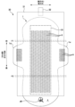
- FIG. 2 is a plan view of the napkin 1 in an unfolded state, as viewed from the skin side.
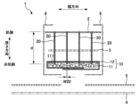
- FIG. 1 is a schematic cross-sectional view of a napkin 1.
- FIG. 2 is a plan view of an individually wrapped napkin 30 in an unfolded state, as viewed from the non-skin side.
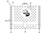
- FIG. 2 is a plan view of an individually wrapped napkin 30 in the process of being unfolded, as viewed from the skin side.
- FIG. 2 is a plan view of an individually wrapped napkin 30.
- FIG. 6A is a perspective view of a napkin package 40
- FIG. 6B is a view showing the state in which the container 41 has been opened.
- FIG. 4A and 4B are diagrams illustrating a decorative sheet 50.
- 10A and 10B are diagrams illustrating the decorative sheet 50.
- FIG. 2 is a front view of a portion of an individual package 30.
- FIG. 5A to 5C are diagrams illustrating a method for manufacturing the decorative sheet
- Aspect 1 is a decorative sheet for absorbent products that is used for any of absorbent articles, individual packages of absorbent articles, and packages of absorbent articles, and is decorated, comprising a sheet, an adhesive layer provided on the surface of the sheet, and a decorative layer provided on the adhesive layer and having a maximum thickness of 10 ⁇ m or less, wherein the decorative layer is provided in a position visible to a user and protrudes from the surface of the sheet in the thickness direction of the sheet.
- the decorative layer has a small maximum thickness, it can be made to protrude in the thickness direction of the sheet by overlapping with the adhesive layer.
- the protruding, three-dimensional decorative layer the impression is given to the user that the absorbent article has also deformed three-dimensionally to fit the user.
- the decorative layer is more easily visually perceived three-dimensionally. This gives the user the impression that the absorbent article is also three-dimensionally deformed and fitting well.
- the decorative layer is more easily seen three-dimensionally, as if it is protruding from the end toward the inside. This gives the user the impression that the absorbent article is also deformed three-dimensionally and fitting well.
- the surface of the decorative layer has an uneven shape, making it easier to see the decorative layer in a more three-dimensional way. This gives the user the impression that the absorbent article is also three-dimensionally deformed and fitting well.
- the small thickness of the extension portion can suppress a decrease in the visibility of the decorative layer. Since the decorative layer is not located at the end portion where force is likely to be applied, cracks and peeling of the decorative layer can be suppressed, and the quality of the decorative layer can be maintained. Therefore, the user can be given the impression that the absorbent article is also of high quality.
- the extension is short in length, which prevents the aesthetics of the decorative layer from deteriorating. Since the decorative layer is not located at the end where force is likely to be applied, cracks and peeling of the decorative layer are prevented, and the quality of the decorative layer is maintained. This gives the user the impression that the absorbent article is also of high quality.
- the decorative layer can be made to protrude further in the thickness direction of the sheet, making it easier for the decorative layer to be viewed three-dimensionally.
- the aesthetics of the three-dimensional decorative layer can be enhanced.
- a user who visually checks the decorative layer formed from metal foil or holographic foil can be given the impression that the absorbent article is a high-quality product.
- a decorative layer formed from pigment foil has a matte finish, giving the user the impression that the product is calm and reassuring.
- a user who sees the narrow decorative layer can get the impression that the absorbent article is a soft product that deforms delicately and flexibly. Furthermore, a user who sees the decorative layer can easily get the impression that the absorbent article is easily deformed starting from the firmly compressed portion.
- the thickness of the decorative layer and the adhesive layer is reduced, and peeling due to snagging can be suppressed. Furthermore, a user who visually observes the decorative layer can get the impression that the absorbent article is easily deformed starting from the deep compressed portion.
- a decorative sheet for absorbent products according to any one of aspects 1 to 10, having a printed layer provided on the surface of the sheet, with the adhesive layer and the decorative layer provided on a portion of the printed layer.
- a decorative sheet for absorbent products according to any one of aspects 1 to 12, the decorative sheet having a vertical direction and a horizontal direction perpendicular to each other, a first adhesive layer and a second adhesive layer, and when the decorative sheet is stretched in the vertical direction or the horizontal direction whichever has the higher elongation strength, the amount of elongation of the decorative sheet when the first adhesive layer breaks is different from the amount of elongation of the decorative sheet when the second adhesive layer breaks.
- the difference in the way the first adhesive layer and the second adhesive layer stretch causes the three-dimensional appearance of the decorative layer on the first adhesive layer and the decorative layer on the second adhesive layer to differ.
- the user can enjoy the difference between the multiple three-dimensional decorative layers.
- the recessed welded portion in plan view accentuates the height of the decorative layer, making it easier to see the decorative layer in three dimensions. This gives the user the impression that the absorbent article is also deformed three-dimensionally to fit well.
- a user who sees the narrow decorative layer can get the impression that the absorbent article is a soft product that deforms finely and flexibly. Furthermore, a user who sees the decorative layer can easily recognize the presence of the superabsorbent polymer, and can easily get the impression that excretory fluid is absorbed and retained by the superabsorbent polymer.
- the visibility of the code display section is improved, and the reading device can correctly read the code display section.
- the absorbent article when a user visually views the three-dimensional product display section, the absorbent article also gives the impression of being three-dimensionally deformed to fit the user.
- a decorative sheet for absorbent products used in any of an absorbent article, an individual package of an absorbent article, and an absorbent article package will be described using a sanitary napkin as an example of an absorbent article.
- the absorbent article is not limited to a sanitary napkin, but also includes pants-type or tape-type disposable diapers, panty liners, shorts-type napkins, light incontinence pads, urine pads, breast pads, underarm sweat pads, disposable diapers for pets, and other absorbent articles.
- Fig. 1 is a plan view of the napkin 1 in an unfolded state, as seen from the skin side.
- Fig. 2 is a schematic cross-sectional view of the napkin 1.
- the napkin 1 in an unfolded state has a longitudinal direction, a width direction, and a thickness direction that are perpendicular to one another.
- the side that contacts the wearer's lower abdomen is referred to as the "front side,” and the side that contacts the wearer's buttocks is referred to as the “rear side.”
- the side that contacts the wearer's skin is referred to as the “skin side,” and the opposite side is referred to as the "non-skin side.”
- the napkin 1 has a top sheet 2, an intermediate sheet 3, an absorbent 10, a back sheet 4, wing sheets 5, and side sheets 6.
- the materials adjacent in the thickness direction are bonded and fixed using an adhesive (not shown) such as a hot melt adhesive.
- the top sheet 2 and the intermediate sheet 3 are liquid-permeable sheet members, and examples of such members include nonwoven fabrics.
- the back sheet 4 is liquid-impermeable sheet members, and examples of such members include resin films.
- the side sheets 6 are folded back inward in the width direction from the end of the non-skin side of the absorbent 10 to the end of the skin side of the top sheet 2 in the width direction.
- the back sheet 4 and the wing sheets 5 extend outward in the width direction beyond the side sheets 6, forming wing portions 1w in the longitudinal center of the napkin 1.
- the top sheet 2 that comes into contact with the wearer's skin may be a sheet made of cotton, a natural fiber (for example, a sheet member made of 100% cotton, or a mixed sheet of cotton and air-through nonwoven fabric). This can reduce irritation to the wearer's skin. In that case, as shown in the drawings described below, a pattern representing cotton can be provided on the napkin 1, individual package 30, or package 40 to indicate to the user that cotton is used. However, the top sheet 2 does not have to be a cotton sheet.
- the absorbent 10 is a member that absorbs and retains bodily waste inside.
- the absorbent 10 in FIG. 2 has an absorbent core 11 and a core wrap sheet 12 that covers the absorbent core 11.
- the absorbent core 11 is a liquid-absorbent fiber such as pulp fiber or cellulosic absorbent fiber formed into a predetermined shape.
- the core wrap sheet 12 is a liquid-permeable sheet member, such as tissue.
- the configuration of the absorbent 10 is not limited to the above, and may be, for example, a SAP sheet in which an SAP layer is attached to a hydrophilic sheet, or an airlaid sheet in which liquid-absorbent fiber is formed into a sheet by an airlaid method.
- the structure of the napkin is not limited to the above.
- the napkin may not have the wing portion 1w.
- Fig. 3 is a plan view of the unfolded individual napkin wrapper 30 as seen from the non-skin side.
- Fig. 4 is a plan view of the unfolded individual napkin wrapper 30 as seen from the skin side.
- Fig. 5 is a plan view of the individual napkin wrapper 30.
- the individually wrapped napkin 1 package 30 (hereinafter also referred to as “individually wrapped napkin 30") is a napkin 1 individually wrapped in a packaging sheet 31, and includes the napkin 1, the packaging sheet 31, a fastening tape 32, and release sheets 33, 34.
- the packaging sheet 31 is a rectangular sheet member, and examples of the material include a resin film, a nonwoven fabric, paper, and a sheet that combines these by lamination.
- the longitudinal direction of the packaging sheet 31 corresponds to the longitudinal direction of the napkin 1, and the width direction, which is the short side direction of the packaging sheet 31, corresponds to the width direction of the napkin 1.
- the fastening tape 32 is provided at the longitudinal end of the packaging sheet 31.
- the non-skin side of the napkin 1 (i.e. the non-skin side of the backsheet 4) is provided with a plurality of adhesive portions 8, 9, which are formed by applying an adhesive or the like.
- the main body of the napkin 1 is provided with a plurality of rectangular adhesive portions 8 extending in the longitudinal direction, lined up in the width direction.
- the adhesive portions 8 of the main body are used to secure the main body of the napkin 1 to the inner surface of the wearer's underwear.
- the wing portions 1w are also provided with a plurality of rectangular adhesive portions 9 extending in the longitudinal direction, lined up in the width direction. When the napkin 1 is worn, the wing portions 1w are folded and secured to the outer surface of the underwear by the adhesive portions 9.
- the shape, number, and arrangement of the adhesive portions 8, 9 are not limited to those illustrated in FIG. 3.
- the non-skin side of the napkin 1 is fixed to the packaging sheet 31 via a release sheet 33.
- the release sheet 33 covers the adhesive portion 8 of the main body of the napkin 1, allowing the napkin 1 to be easily peeled off when the individual package 30 is opened.
- the wing portion 1w is folded inward in the width direction onto the skin side of the napkin 1.
- the adhesive portion 9 of the wing portion 1w is covered with a release sheet 34.
- the napkin 1 may also be directly and removably fixed to the packaging sheet 31 without the release sheet 33.
- the packaging sheet 31 and napkin 1 are folded from the state shown in FIG. 4 at two folds F1 and F2 along the width direction. Both ends of the packaging sheet 31 folded together with the napkin 1 in the width direction are joined to form a joint 35 as shown in FIG. 5. Examples of the joining method at the joint 35 include well-known joining methods such as heat sealing, ultrasonic sealing, adhesives, and combinations of these.
- a fastening tape 32 is provided across the opening end of the packaging sheet 31. The user grasps the fastening tape 32, unfolds the folds F1 and F2, and opens the individual package 30.
- the configuration of the individual packaging body 30 is not limited to the above.
- the number of folds F1, F2 of the packaging sheet 31 is not limited to two, and may be one or three or more.
- the packaging sheet 31 and napkin 1 may be folded not only at the folds F1, F2 along the width direction, but also at the folds along the length direction.
- the packaging sheet 31 and napkin 1 may be folded separately. In other words, the packaging sheet 31 may be folded while enclosing the napkin 1 that has already been folded.
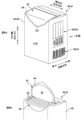
- Fig. 6A is a perspective view of a napkin package 40
- Fig. 6B is a view showing the opened state of a container 41.
- the napkin package 40 (hereinafter also referred to as "package 40") has a plurality of individually wrapped napkins 30 and a container 41 that contains them.
- the container is not limited to containing individually wrapped absorbent articles, and may directly contain one or a plurality of absorbent articles that are not individually packaged, such as disposable diapers.
- FIG. 6A shows an example of a container 41 having vertical, horizontal, and front-to-rear directions, and includes a rectangular parallelepiped main body 42 and a sealing member 43.
- the sealing member 43 is provided on the rear surface 41B of the package 40 (container 41). More specifically, the sealing member 43 is provided on the upper rear portion of the container 41.
- a knob 431 is provided in the center of the left-right direction of the sealing member 43.
- a cut line 44 (e.g., a perforation) is formed in the portion of the main body 42 covered by the sealing member 43.
- the shape and configuration of the container 41 illustrated in FIG. 6A are merely examples and are not limited thereto.
- the container may be a rectangular container that does not have a sealing member 43, or a container that is a standing pouch type or a flat bag.
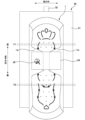
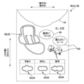
- FIG. 7 is a front view of the package 40.
- Fig. 8 is a rear view of the package 40.
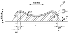
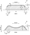
- Figs. 9, 10A and 10B are diagrams for explaining the decorative sheet 50.
- the container 41 (specifically, the main body 42) of the napkin package 40 uses a decorated decorative sheet 50 for absorbent products.
- the decorative sheet 50 has a sheet 51, an adhesive layer 52 provided on the surface of the sheet 51, and a decorative layer 53 provided on the adhesive layer 52 and having a maximum thickness of 10 ⁇ m or less.
- the decorative layer 53 include metal foil, holographic foil, and pigment foil (details will be described later).
- the decorative layer 53 is provided in a portion visible to the user, and protrudes from the surface of the sheet 51 in the thickness direction of the sheet 51.
- the adhesive layer 52 formed to protrude on the surface of the sheet 51 causes the decorative layer 53 to protrude above the surrounding surface of the sheet 51. Therefore, the decoration expressed by the decorative layer 53 is visually recognized by the user as a three-dimensional decoration.
- the portion where the decorative layer 53 and the adhesive layer 52 overlap is also referred to as the "three-dimensional decorative portion 54.” As shown in Figures 9 and 10A, the portion of the adhesive layer 52 that does not overlap with the decorative layer 53 (52E) is not included in the three-dimensional decorative portion 54.
- a three-dimensional decorative portion 54 (adhesive layer 52 + decorative layer 53) is provided on the outer surface of the container 41 of the package 40, and the three-dimensional decorative portion 54 protrudes to the outside of the container 41.
- the three-dimensional decorative portion 54 expresses a pattern of multiple curves d1 ( Figure 7), a flower outline or petal pattern d2 ( Figure 7), or a design d3 ( Figure 7) of a napkin 1.
- a three-dimensional decoration (three-dimensional decorative portion 54) can be formed by providing the decorative layer 53 on the adhesive layer 52.
- a user who visually recognizes the three-dimensional decorative portion 54 provided on the container 41 of the package 40 is likely to get the impression that it is a three-dimensional product. Therefore, the user is likely to get the impression that the napkin 1 contained in the container 41 is a product that deforms three-dimensionally, fits the body, and is unlikely to leak.
- the three-dimensional decorative portion 54 is visible to users in stores where the packages 40 are displayed, in restrooms where the packages 40 are stored, etc. A user who visually recognizes the three-dimensional decorative portion 54 before using the napkin 1 can use the napkin 1 with confidence.
- the type of decoration expressed by the three-dimensional decorative portion 54 is not particularly limited, and examples include letters, numbers, symbols (e.g., musical notes and signs), figures (e.g., circles, polygons, hearts, stars), designs (e.g., shapes of objects or pictures of animals, plants, and characters), geometric patterns, colors (areas that have a certain color difference from the color of the sheet 51), or combinations of these.
- the three-dimensional decorative portion 54 shown in FIG. 7 is one example, and the shape, number, size, and arrangement of the three-dimensional decorative portion 54 are not particularly limited.
- the adhesive layer 52 maintains a raised state on the surface of the sheet 51 and is a layer formed from a material having adhesive properties that allow the sheet 51 and the decorative layer 53 to adhere to each other.
- a material forming the adhesive layer 52 is a colorless and transparent ultraviolet-curing adhesive. However, this is not limited to this, and other light-curing adhesives may also be used. It is advisable to adjust the viscosity of the adhesive layer 52 so that the adhesive layer 52 does not easily soak into the sheet 51 and is raised on the sheet 51.
- the sheet 51 that constitutes the decorative sheet 50 include a resin film, a nonwoven fabric, paper, and a sheet that is a composite of these by lamination.
- the three-dimensional decorative portion 54 may be provided at any position on the outer surface of the container 41 of the package 40. Preferably, as shown in FIG. 7, it is provided on the front surface 41F of the container 41 of the package 40. This makes it easier for users to see the three-dimensional decorative portion 54 in stores, etc.
- the front surface of the container 41 refers to the largest surface among the multiple surfaces of the container 41, or the surface on which the sales name (brand name), the number of containers, etc. are written in large letters.
- the sealing member 43 is provided on the back surface 41B of the container 41 of the package 40, and that the back surface 41B of the container 41 does not have a three-dimensional decorative portion 54.
- the user grips the back surface 41B of the container 41, or the tensile force of the sealing member 43 acts on the back surface 41B of the container 41. Therefore, by not providing the three-dimensional decorative portion 54 on the back surface 41B (opening surface) of the container 41, it is possible to prevent the three-dimensional decorative portion 54 from falling off and adhering to the user or the napkin 1 when opening.
- the three-dimensional decorative portion 54 may be provided on the napkin 1 or the individual napkin packaging body 30 instead of the package 40, or the three-dimensional decorative portion 54 may be provided on the napkin 1 or the individual napkin packaging body 30 in addition to the package 40.
- the decorative sheet 50 may be used on at least one of the napkin 1, the individual napkin packaging body 30, and the napkin package 40.
- the decorative sheet 50 can be used for the packaging sheet 31 and the peel-off sheets 33 and 34.
- the pattern d4 on the outer surface of the packaging sheet 31 shown in FIG. 5 and the pattern d5 on the peel-off sheet 34 shown in FIG. 4 can be made into the three-dimensional decorative portion 54. This allows the user to visually recognize the three-dimensional decorative portion 54 when removing the individual package 30 from the package 40 or when opening the individual package 30.
- the decorative sheet 50 can be used for the back sheet 4, wing sheet 5, etc.
- the pattern d6 on the non-skin side of the back sheet 4 shown in FIG. 3 can be made into the three-dimensional decorative portion 54. This allows the user to visually recognize the three-dimensional decorative portion 54 when removing the napkin from the individual package 30 and putting it on in underwear.
- the user can visually confirm the three-dimensional decorative portion 54 before using the napkin 1. This allows the user to easily get the impression that the napkin 1 has been three-dimensionally deformed to fit, allowing the user to use it with confidence.
- the decorative layer 53 is a layer formed of any one of metal foil, holographic foil, and pigment foil.
- the aesthetics of the three-dimensional decorative portion 54 can be enhanced.
- the three-dimensional decorative portion 54 formed of metal foil or holographic foil is expressed in a color having a metallic luster such as gold or silver, and is easy to notice. Therefore, a user who visually checks the container 41 of the package 40 is likely to pay attention to the glittering three-dimensional decorative portion 54, and is likely to have the impression that the napkin 1 is deformed three-dimensionally.
- the three-dimensional decorative portion 54 having a metallic luster makes the user more likely to have the impression that it is a high-quality product.
- the user is likely to have the impression that the napkin 1 contained in the container 41 is a high-quality product (for example, it is less likely to leak, is comfortable to wear, etc.), and can use the napkin 1 with confidence.
- the three-dimensional decorative portion 54 formed of pigment foil has a matte decoration that is matte, and can give the user the impression that it is a calm and reassuring product.
- users can have peace of mind that there are no foreign objects such as metals inside the napkin 1 that is stored inside.
- metal foil examples include metal that has been hammered and rolled out thin and flat, thin and flat sheets containing metal (coated films of metal powder pigments, metal vapor deposition films), and sheets in which a synthetic resin layer is laminated onto these.
- metals contained in metal foil include gold, silver, copper, tin, brass, and aluminum.
- Holographic foil is a thin, flat sheet that uses the prism effect to reflect incoming light in rainbow colors. By creating a finely textured pattern on the surface, viewers of the reflected light can see a specific pattern.
- An example of a pigment foil is a sheet in which a pigment coating film is laminated on a synthetic resin layer.
- examples of the pigment color include red, blue, yellow, black, and white, but are not limited to these.
- the decorative layer 53 may also be a foil material other than metal foil, holographic foil, and pigment foil.
- the maximum thickness of the adhesive layer 52 is greater than the maximum thickness of the decorative layer 53.
- the thickness of the adhesive layer 52 is in the range of about 10 to 80 ⁇ m
- the thickness of the decorative layer 53 is in the range of about 4 to 6 ⁇ m. This allows the thin decorative layer 53 to protrude further from the surface of the surrounding sheet 51. This makes the three-dimensional decorative portion 54 more three-dimensional, making it easier for the user to recognize that a three-dimensional decoration is provided.
- the thickness of the decorative layer 53 (for example, 53t in FIG. 9) is the length in the direction perpendicular to the surface of the decorative layer 53, as described above.
- the thickness of the adhesive layer 52 (for example, thickness t2 in FIG. 9) is the length in the thickness direction of the sheet 51.
- the adhesive layer 52 which is an ultraviolet-curing adhesive
- the decorative layer 53 is adhered to the adhesive layer 52 by the adhesiveness of the partially cured adhesive layer 52.
- Examples of the cross-sectional shape of the three-dimensional decorative portion 54 include the shapes shown in Figures 9, 10A, and 10B.
- the three-dimensional decorative portion 54 shown in the figures has a length in a predetermined direction. As shown, it is preferable that the three-dimensional decorative portion 54 (the portion where the decorative layer 53 and the adhesive layer 52 overlap) has portions with different thicknesses. For example, in the three-dimensional decorative portion 54 in Figure 9, the center portion in a predetermined direction is recessed and thin. In the three-dimensional decorative portion 54 in Figure 10A, the thickness of the end portion in a predetermined direction is thinner than the thickness of the adjacent portions.
- the three-dimensional decorative portion 54 is more easily perceived three-dimensionally. Therefore, when a user sees the three-dimensional decorative portion 54, they are more likely to get the impression that the napkin 1 is also deforming three-dimensionally to fit them better. In addition, the appearance of the three-dimensional decorative portion 54 changes depending on the angle. Therefore, the user is more likely to get the impression that the napkin 1 is deforming along with the body, following the movement of the body, rather than deforming uniformly.
- the thickness of the end portion 54E in a predetermined direction is smaller than the thickness of the inner portion 54I in the predetermined direction adjacent to the end portion 54E.
- the three-dimensional decorative portion 54 is visually perceived as protruding from the end portion 54E toward the inner portion 54I in a specified direction, making the three-dimensional decorative portion 54 easier to visually perceive as being more three-dimensional. Therefore, a user who visually perceives the three-dimensional decorative portion 54 is more likely to get the impression that the napkin 1 has also deformed three-dimensionally to fit better.
- the central portion of the three-dimensional decorative portion 54 in a predetermined direction is recessed (towards the sheet 51 in the thickness direction).
- the surface of the three-dimensional decorative portion 54 has an uneven shape, making the three-dimensional decorative portion 54 easier to see three-dimensionally. Therefore, a user who sees the three-dimensional decorative portion 54 is more likely to get the impression that the napkin 1 is also deforming three-dimensionally to fit. Furthermore, the user is more likely to get the impression that the napkin 1 is deforming along the body rather than deforming uniformly, and is deforming to follow the movement of the body.
- the thickness of the three-dimensional decorative portion 54 in a specified direction other than the ends may be constant as shown in FIG. 10A, or the central portion of the three-dimensional decorative portion 54 in a specified direction may bulge in a convex shape and have a large thickness.
- the adhesive layer 52 may have an extension portion 52E that extends further to one side in a predetermined direction than the decorative layer 53.
- the adhesive layer 52 may extend to both sides in the predetermined direction as shown, or may extend to only one side in the predetermined direction.
- the maximum thickness t1 of the extension portion 52E of the adhesive layer 52 is smaller than the maximum thickness t2 of the portion of the adhesive layer 52 that overlaps with the decorative layer 53 (t1 ⁇ t2).
- the small thickness of the extension 52E which is a single adhesive layer 52, can prevent the extension 52E from impairing the visibility of the decorative layer 53.
- the adhesive layer 52 is formed of a material having adhesiveness and has elasticity, it is likely to deform in accordance with the sheet 51. Therefore, peeling of the adhesive layer 52 from the sheet 51 can be suppressed.
- the thickness of the extension 52E is small, the extension 52 is more likely to deform in accordance with the sheet 51.
- the decorative layer 53 is not located at the end where force is likely to be applied, peeling of the adhesive layer 52 and the decorative layer 53 and cracks in the decorative layer 53 can be suppressed.
- a user who visually recognizes the three-dimensional decorative portion 54, which maintains its quality, is likely to have the impression that the napkin 1 is also a high-quality product.
- the length L1 in a given direction of the extension portion 52E is shorter than the length L2 in a given direction of the portion of the adhesive layer 52 that overlaps with the decorative layer 53 (L1 ⁇ L2).
- the provision of the extension 52E can prevent peeling between the adhesive layer 52 and the decorative layer 53 and cracks in the decorative layer 53.
- the extension 52E can prevent peeling between the adhesive layer 52 and the decorative layer 53 and cracks in the decorative layer 53.
- the aesthetics of the decorative layer 53 such as metallic luster
- the adhesive layer 52 does not have to have the extension portion 52E. In other words, the entire surface of the adhesive layer 52 may be covered with the decorative layer 53.
- the target parts can be compared by visually observing them, or they can be compared based on images of the target parts magnified and photographed using an optical microscope. Comparisons can also be made based on cross-sectional images of the target parts cut. The comparisons of thickness and length of each part described below can also be made using similar methods.
- the napkin 1 has a compressed portion 20 that is compressed in the thickness direction from the skin-facing side of the top sheet 2. Therefore, a user looking at the skin-facing side of the napkin 1 can visually see the compressed portion 20.
- the napkin 1 is thinner than the surrounding areas, and the density of the materials (fibers) that make up the napkin 1 is higher.
- the top sheet 2, intermediate sheet 3, and absorbent body 10 are compressed in the thickness direction. However, it is sufficient for the compressed portion 20 to compress the napkin 1 in the thickness direction from the skin-facing side of the top sheet 2, and it does not have to reach the absorbent body 10, for example.
- the napkin 1 shown in FIG. 1 has a linear compressed portion 21 in which dot-like compressed portions are arranged in a line, and a plurality of discretely arranged dot-like compressed portions 22.
- the number, shape, and arrangement of the compressed portions 20 are not particularly limited.
- the linear compressed portion may be a compressed portion in which the compressed portions are continuously compressed in a groove shape.
- the minimum width of the decorative layer 53 of the decorative sheet 50 (here, the container 41) (i.e., the minimum width of the three-dimensional decorative portion 54) is smaller than the minimum width W20 (Fig. 2) of the compressed portion 20.
- the minimum width W20 (Fig. 2) of the compressed portion 20.
- users who focus on the three-dimensionally protruding decorative layer 53 are more likely to recognize the three-dimensionally recessed compressed portion 20 when looking at the skin side of the napkin 1.
- Users who view the narrow decorative layer 53 in particular are more likely to recognize the wide compressed portion 20. Because the thickness of the napkin 1 is thin at the compressed portion 20, users are more likely to get the impression that the napkin 1 is deforming three-dimensionally to fit the body, starting from the compressed portion 20.
- the width W53 of the decorative layer 53 is defined as the direction perpendicular to the direction in which the decorative layer 53 extends, for example, as in the curved pattern d1 shown in FIG. 7, when the decorative layer 53 (three-dimensional decorative portion 54) extends linearly, or when the decorative layer 53 forms the outline of a pattern (e.g., a napkin).
- the width direction is defined as the direction perpendicular to the direction in which the linear portion extends.
- the width direction is defined as the short side direction of the rectangular shape circumscribed by the three-dimensional decorative portion 54 in a plan view.
- the length of the decorative layer 53 in the above-mentioned width direction is defined as the width.
- the width of the decorative layer 53 is defined as the thickness of the line forming the letter or the like.
- the predetermined direction in this specification may be the width direction along the width of the decorative layer 53, or may be a direction intersecting the width direction.
- the width W20 of the compressed portion 20 is also defined as the length in the direction perpendicular to the direction in which the linear compressed portion 21 extends, and is defined as the length in the short direction of the rectangular shape circumscribing the dot-like compressed portion 22 in a plan view.
- the napkin 1 illustrated in FIG. 2 also has an absorbent core 11 containing a superabsorbent polymer 111.
- the absorbent core 11 is made by adding the superabsorbent polymer 111 to liquid-absorbent fibers such as pulp fibers, and molding the mixture into a predetermined shape.
- the minimum width (W53) of the decorative layer 53 is smaller than the average particle size of the superabsorbent polymer 111 before it absorbs liquid.
- (1) Prepare a digital microscope manufactured by Keyence Corporation (product name: VHX-1000, zoom lens: ⁇ 20 to ⁇ 200, or equivalent) and the accompanying software in a constant temperature and humidity room with a temperature of 20 ⁇ 5°C and a humidity of 65 ⁇ 5% RH.
- a plurality of superabsorbent polymers 111 taken out from the target napkin 1 are left to stand in the above-mentioned temperature and humidity chamber for 24 hours.
- the superabsorbent polymer 111 is photographed with the digital microscope.
- the average particle size of the superabsorbent polymer 111 means the median diameter in the particle size distribution (number basis). Specifically, a particle size distribution (number basis) of the circle-equivalent diameter CD of 1,000 superabsorbent polymer particles is created using the accompanying software, and the median diameter is determined from the particle size distribution (number basis) to be the average particle size.
- the absorbent core 11 does not need to contain the superabsorbent polymer 111.
- the napkin 1 has a compressed portion 20
- the maximum thickness t3 ( Figure 9) of the three-dimensional decorative portion 54 which is the portion where the decorative layer 53 and the adhesive layer 52 overlap, is smaller than the minimum depth d ( Figure 2) of the compressed portion 20 (t3 ⁇ d).
- the maximum thickness t3 of the three-dimensional decorative portion 54 By keeping the maximum thickness t3 of the three-dimensional decorative portion 54 to a moderate level and not too thick, it is possible to prevent the three-dimensional decorative portion 54 from getting caught. This makes it possible to prevent the three-dimensional decorative portion 54 from peeling off the sheet 51. In this way, a user who visually checks the three-dimensional decorative portion 54, whose quality has been maintained, is more likely to have the impression that the napkin 1 is also a high-quality product. On the other hand, the user is more likely to recognize the compressed portion 20, which has a good depth. As a result, the user is more likely to get the impression that the napkin 1 is deforming three-dimensionally to fit the body, starting from the compressed portion 20. By actually compressing down to the highly rigid absorbent body 10, the napkin 1 is more likely to bend starting from the compressed portion 20, making it easier for it to deform three-dimensionally.
- the decorative sheet 50 may have not only the three-dimensional decorative portion 54 but also a flat printed layer 60 provided on the surface of the sheet 51, that is, a normal printed layer 60 printed with ink.
- the three-dimensional decorative portion 54 adheresive layer 52 and decorative layer 53
- a three-dimensional decorative portion 54 with a curved pattern d1 is provided on top of a printed layer 60 that is a plurality of curved patterns p1.
- a three-dimensional decorative portion 54 with a petal pattern d2 is provided on top of a printed layer 60 that represents a flower color p2.
- the printing layer 60 is covered with the three-dimensional decorative part 54, the printing layer 60 is less likely to peel off. Conversely, even if the three-dimensional decorative part 54 peels off from the sheet 51, the printing layer 60 is visible. Therefore, deterioration in the appearance quality of the decorative sheet 50 can be suppressed, and the user's impression of the high quality of the napkin 1 is also ensured.
- the napkin 1 has an absorbent core 11 and a core wrap sheet 12 that covers the surface of the absorbent core 11.
- the tensile strength of the adhesive layer 52 that overlaps the decorative layer 53 is higher than the tensile strength of the core wrap sheet 12 in the width direction of the napkin 1.
- the up-down and left-right directions (or the up-down and front-back directions) of the container 41 shown in FIG. 6 correspond to the mutually orthogonal vertical and horizontal directions of the decorative sheet 50.
- the longitudinal and width directions shown in FIG. 3 correspond to the vertical and horizontal directions of the decorative sheet 50.
- the decorative sheet 50 has the vertical or horizontal direction, whichever has the higher tensile strength.
- the extension amount of the decorative sheet 50 at which the adhesive layer 52 of the three-dimensional decorative portion 54 breaks is defined as the first extension amount (mm)
- the extension amount of the core wrap sheet 12 at which the core wrap sheet 12 breaks is defined as the second extension amount (mm).
- the first extension amount is greater than the second extension amount.
- the time when the adhesive layer 52 breaks is the earlier of when cracks begin to occur in the adhesive layer 52 or when peeling of the adhesive layer 52 from the decorative sheet 50 begins to occur.
- the time when the core wrap sheet 12 breaks is when cracks or tears begin to occur in the core wrap sheet 12.
- the core wrap sheet 12, which is a material constituting the napkin 1, is formed with a strength that will not break while the napkin 1 is being worn. It is preferable that the adhesive layer 52 of the three-dimensional decorative portion 54 has a stronger strength against elongation forces and is less likely to break than the core wrap sheet 12. This prevents the adhesive layer 52 from breaking and falling off the sheet 51 even if the decorative sheet 50 (here, the container 41 of the package 40) is stretched at various times, such as during production, distribution, or when handled by the user. By maintaining the appearance quality of the three-dimensional decorative portion 54, users are more likely to get the impression that it is a high-quality product, and are more likely to get the impression that the napkin 1 has high-quality performance (performance such as low leakage and comfortable wear).
- the comparison of the elongation at break can be carried out by a known method using a tensile tester (e.g., Instron Model 5965 or equivalent).
- a tensile tester e.g., Instron Model 5965 or equivalent.
- the direction with the higher tensile strength is determined between the vertical and horizontal directions of the decorative sheet 50.
- the decorative sheet 50 is cut to a predetermined size to form a sample.
- a sample with the vertical direction of the decorative sheet 50 e.g., the vertical direction of the package 40
- a sample with the horizontal direction of the decorative sheet 50 e.g., the left-right direction of the package 40
- the sample is a rectangle (e.g., 100 mm long in the measurement direction x 25 mm wide) with the measurement direction of the stretching as the longitudinal direction.
- both ends of the sample are clamped by the chucks of a tensile tester (distance between chucks: 50 mm), and the tensile strengths (N) are compared when the sample is stretched to a predetermined length at a tensile speed of 100 mm/min.
- the direction in which the sample with the higher tensile strength is stretched is the direction with the higher tensile strength.
- the decorative sheet 50 is cut to a predetermined size to form a sample including the three-dimensional decorative portion 54.
- the size of the sample is a rectangle (for example, 100 mm long in the measurement direction x 25 mm wide) with the longitudinal direction (measurement direction) being the direction with the higher elongation strength of the vertical or horizontal directions of the decorative sheet 50.
- each material is separated from the napkin 1 using a cold spray or the like, and the core wrap sheet 12 is taken out.
- the core wrap sheet 12 is also cut to a predetermined size (a rectangle with the longitudinal direction being the measurement direction of elongation (width direction of the napkin 1), 100 mm long x 25 mm wide) to form a sample.
- both ends of each sample are clamped with the chucks of a tensile testing machine (distance between chucks 50 mm), and the sample is stretched while being observed at a tensile speed of 100 mm/min. Then, the amount of elongation of the sample when the adhesive layer 52 of the three-dimensional decorative portion 54 breaks (first elongation amount) and the amount of elongation of the sample when the core wrap sheet 12 breaks (second elongation amount) are calculated and compared.
- the decorative sheet 50 preferably has multiple three-dimensional decorative parts 54 with different amounts of elongation when the adhesive layer 52 breaks.
- the decorative sheet 50 has a first adhesive layer 52 and a second adhesive layer 52
- the amount of elongation of the decorative sheet 50 when the first adhesive layer 52 breaks should be different from the amount of elongation of the decorative sheet 50 when the second adhesive layer 52 breaks.
- the decorative sheet 50 forming the package 40 in FIG. 7 has an adhesive layer 52 (first adhesive layer) forming the curved pattern d1, and an adhesive layer 52 (second adhesive layer) forming the napkin design.
- the width of the adhesive layer 52 of the curved pattern d1 is different from the width of the adhesive layer 52 of the napkin design. Therefore, the adhesive layer 52 of the curved pattern d1 and the adhesive layer 52 of the napkin design can have different amounts of elongation (ease of stretching) when broken.
- the adhesive layer 52 of one three-dimensional decorative part 54 and the adhesive layer 52 of another three-dimensional decorative part 54 can have different thicknesses of the adhesive layer 52 or different planar shapes of the adhesive layer 52 (for example, the presence or absence of curved and straight parts) to have different amounts of elongation (ease of stretching) when broken.
- a portion of the adhesive layer 52 that stretches a large amount when it breaks is one that stretches easily and is less likely to break. Conversely, a portion of the adhesive layer 52 that stretches a small amount when it breaks is one where the adhesive layer 52 stretches less easily. In this way, by having portions of the adhesive layer 52 that stretch easily and portions that stretch less easily, when an external force is applied to the decorative sheet 50, the appearance changes due to the difference in stretch of the multiple three-dimensional decorative portions 54. This makes it easier for the user to focus on the three-dimensional decorative portions 54.
- the amount of elongation at break of the first adhesive layer 52 and the second adhesive layer 52 can be measured in the same manner as the method using the tensile tester described above.
- a sample including the first adhesive layer 52 (three-dimensional decorative portion 54) and a sample including the second adhesive layer 52 (three-dimensional decorative portion 54) are formed, and each sample is stretched to determine the amount of elongation of the sample when breakage occurs in the adhesive layer 52, and then compared.
- the package 40 (container 41) is often provided with a code display section 61 (barcode, QR code (registered trademark), etc.) that can be read by an optical reading device.
- a code display section 61 barcode, QR code (registered trademark), etc.
- the code display section 61 is formed by a printing layer 60 that does not overlap the adhesive layer 52 and the decorative layer 53.
- the outline of the decoration formed by the ink printing layer 60 is clearer than that of the three-dimensional decorative portion 54. Therefore, by forming the code display portion 61 from the flat printing layer 60 rather than the three-dimensional decorative portion 54, visibility is improved and the code display portion 61 is correctly read by the reading device.
- the package 40 may have information about the napkin 1 contained therein written on a table or the like.
- This information display group 63 (such as the sales name, constituent materials, usage instructions, manufacturer, etc.) is displayed in relatively small characters. For this reason, the information display group 63 is also formed not by the three-dimensional decorative portion 54 but by a flat printing layer 60 made of ink, making it easier for the user to read the information display group 63.
- the package 40 (container 41) is often provided with an item display section 62 that represents the napkin 1 contained therein.
- the item display section 62 is formed by the three-dimensional decorative section 54 (adhesive layer 52 and decorative layer 53).
- the user sees the product display section 62 displayed three-dimensionally, and is more likely to get the impression that the actual napkin 1 contained therein has also been deformed three-dimensionally to fit.
- the product display section 62 displayed three-dimensionally, and is more likely to get the impression that the actual napkin 1 contained therein has also been deformed three-dimensionally to fit.
- the package 40 may be provided with a napkin group display section 64 for products sold under the same brand name.
- the napkin group display section 64 the shape of other napkins with different sizes and performance (whether or not they have wings 1w, whether they are for day use or night use, etc.) is displayed along with the napkin 1 contained therein.
- the napkin group display section 64 is provided on the back surface 41B (opening surface) of the container 41, and is therefore formed by the printing layer 60, but this napkin group display section 64 may also be formed by the three-dimensional decorative section 54.
- the napkin group display section 64 is provided on a surface other than the opening surface of the package 40, it is preferable for it to be formed by the three-dimensional decorative section 54. In this way, the user can be given the impression that not only the napkin 1 contained therein, but also the other napkins are three-dimensionally deformed.
- Each of the markings (61-64) on the package 40 may be formed by the three-dimensional decorative portion 54, or may be formed by a flat printing layer 60 made of ink.
- FIG. 11 is a front view of a portion of an individual package 30.
- a decorative sheet 50 is used for the packaging sheet 31 of an individual package 30 of napkins.
- a three-dimensional decorative portion 54 is provided on the outer surface of the packaging sheet 31.
- joints 35 are formed on both ends in the width direction of the individual package 30 illustrated in FIG. 11.
- the opposing packaging sheets 31 are joined by a welding portion 36.
- the welding portion 36 is also visible when the decorative layer 53 of the packaging sheet 31 is viewed from above.
- a plan view is a view of the individual package 30 in the thickness direction of the packaging sheet 31 as shown in FIG. 5.
- the thickness of the packaging sheet 31 is thinner at the welded portion 36, and the welded portion 36 is recessed in the thickness direction of the individual package 30 compared to the surrounding area. Therefore, the user can visually recognize the decorative layer 53 (three-dimensional decorative portion 54) protruding in the thickness direction along with the welded portion 36 recessed in the thickness direction. This makes the height of the decorative layer 53 more prominent, making the three-dimensional decorative portion 54 more easily visually recognized. This makes it easier for the user to get the impression that the napkin 1 contained in the individual package 30 has been deformed three-dimensionally to fit.
- the napkin package 40 may also be provided with a welded portion that seals the container 41. Therefore, when a decorative sheet 50 is used for the container 41, it is preferable that the welded portion and the three-dimensional decorative portion 54 are simultaneously visible in a plan view of the container 41 (when the container 41 is viewed in the thickness direction of the decorative sheet 50).
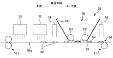
- FIG. 12 is a diagram illustrating a manufacturing method of the decorative sheet 50.
- the decorative sheet 50 described above can be manufactured by a manufacturing device 70 illustrated in Fig. 12.
- the manufacturing device 70 has a conveying mechanism 71, an ink ejection device 72, an adhesive ejection device 73, a first irradiation device 74, a decorative layer conveying mechanism 75, and a second irradiation device 76.
- the transport mechanism 71 is a mechanism for transporting the continuous body 51c of the sheet 51 in the transport direction.
- Examples of the transport mechanism 71 include a transport roller as shown in FIG. 12 and a belt conveyor (not shown).
- the ink ejection device 72 ejects ink onto the continuous body 51c of the sheet 51 transported in the transport direction by the transport mechanism 71, and forms a flat normal printing layer 60.
- an adhesive discharge device 73 discharges adhesive to form an adhesive layer 52 directly onto the continuum 51c of the sheet 51 or onto the print layer 60.
- a colorless and transparent ultraviolet-curing adhesive is discharged.
- a first irradiation device 74 irradiates the adhesive layer 52 with light (ultraviolet light in this case) to harden the adhesive layer 52, hardening it.
- the first irradiation device 74 irradiates ultraviolet light to the extent that the adhesive layer 52 is not completely hardened. In this way, the shape of the adhesive layer 52 is fixed while ensuring adhesion. To achieve this, the intensity of the ultraviolet light and the irradiation time are adjusted.
- an inkjet device is used as an example of the ink ejection device 72 and the adhesive ejection device 73.
- the printing layer 60 and the adhesive layer 52 may be formed using various printing methods (liquid application methods) such as gravure printing and offset printing.
- the decorative layer transport mechanism 75 supplies the continuum 53c of the decorative layer 53 onto the adhesive layer 52.
- An example of the decorative layer transport mechanism 75 is a device having a pay-out roller (not shown) that pays out the continuum 53c of the decorative layer 53, a transport roller 751, and a wind-up roller (not shown) that winds up the remainder of the continuum 53c of the decorative layer 53.
- the length of the continuum 53c of the decorative layer 53 is equal to or greater than the length of the area in which the adhesive layer 52 is formed.
- the continuum 53c of the decorative layer 53 covers all of the one or more adhesive layers 52 formed on the continuum 51c of the sheet 51.
- the continuum 53c of the decorative layer 53 is supplied so as to contact the surface of the adhesive layer 52. Since the adhesive layer 52 is sticky, the continuum 53c of the decorative layer 53 is attached to the adhesive layer 52.
- the continuum 53c of the decorative layer 53 and the adhesive layer 52 are conveyed, and the decorative layer 53 attached to the adhesive layer 52 is separated from the decorative layer 53 that has not come into contact with the adhesive layer 52.
- the remaining portion of the continuum 53c of the decorative layer 53 that has not been attached to the adhesive layer 52 is wound up on a winding roller and collected.
- the second irradiation device 76 irradiates the adhesive layer 52 with light (ultraviolet light in this case), completely curing the adhesive layer 52 through the decorative layer 53. This causes the adhesive layer 52 and the decorative layer 53 to bond strongly together and become one, forming the three-dimensional decorative portion 54.
- a decorative layer 53 is provided on the adhesive layer 52, and the decorative layer 53 can form a three-dimensional decorative portion 54 that protrudes from the surface of the sheet 51 in the thickness direction of the sheet 51.
- the decorative sheet 50 with the three-dimensional decorative portion 54 formed thereon for any of the napkins 1, the individual napkin wrappers 30, and the napkin packages 40 the user can be given the impression that the product is three-dimensional.
- the above manufacturing method is only one example, and the manufacturing method of the decorative sheet 50 is not particularly limited.
- Napkins (absorbent articles), 2 surface sheet, 3 middle sheet, 4 back seat, 5 wing seat, 6 side seat, 8 Adhesive part, 9 Adhesive part, 10 absorbent body, 11 absorbent core, 12 core wrap sheet, 20 Compression section, 30 Individually wrapped napkins, 31 Packaging sheet, 32 Fastening tape, 33 Release sheet, 34 Release sheet, 35 joint part, 36 weld part, 40 packages of napkins, 41 container, 42 main body portion, 43 sealing member, 50 Decorative sheet, 51 seats, 52 adhesive layer, 52E extension part, 53 decorative layer, 54 three-dimensional decorative portion, 60 printing layer, 61 Code display unit, 62 Item display unit, 63 information display group, 64 napkin group display unit, 70 Manufacturing device, 71 Conveying mechanism, 72 Ink ejection device, 73 Adhesive ejection device, 74 first irradiation device, 75 Decoration layer conveying mechanism, 76 second irradiation device,
Landscapes
- Health & Medical Sciences (AREA)
- Epidemiology (AREA)
- Engineering & Computer Science (AREA)
- Biomedical Technology (AREA)
- Heart & Thoracic Surgery (AREA)
- Vascular Medicine (AREA)
- Life Sciences & Earth Sciences (AREA)
- Animal Behavior & Ethology (AREA)
- General Health & Medical Sciences (AREA)
- Public Health (AREA)
- Veterinary Medicine (AREA)
- Mechanical Engineering (AREA)
- Absorbent Articles And Supports Therefor (AREA)
- Wrappers (AREA)
Abstract
Description
吸収性物品と、吸収性物品の個包装体と、吸収性物品のパッケージの何れかに使用され、且つ装飾が施された吸収性製品用の装飾シートであって、
シートと、
前記シートの表面に設けられた接着剤層と、
前記接着剤層の上に設けられ、且つ最大厚みが10μm以下である装飾層と、を有し、
前記装飾層は、ユーザーが視認可能な部位に設けられており、前記シートの厚さ方向に前記シートの前記表面から突出していることを特徴とする吸収性製品用の装飾シートである。
本発明の他の特徴については、本明細書及び添付図面の記載により明らかにする。
態様1は、吸収性物品と、吸収性物品の個包装体と、吸収性物品のパッケージの何れかに使用され、且つ装飾が施された吸収性製品用の装飾シートであって、シートと、前記シートの表面に設けられた接着剤層と、前記接着剤層の上に設けられ、且つ最大厚みが10μm以下である装飾層と、を有し、前記装飾層は、ユーザーが視認可能な部位に設けられており、前記シートの厚さ方向に前記シートの前記表面から突出していることを特徴とする吸収性製品用の装飾シートである。
以下、吸収性物品として生理用ナプキンを例に挙げ、吸収性物品と、吸収性物品の個包装体と、吸収性物品のパッケージの何れかに使用される吸収性製品用の装飾シートの実施形態を説明する。吸収性物品は、生理用ナプキンに限らず、パンツ型又はテープ型の使い捨ておむつ、パンティーライナー、ショーツ型ナプキン、軽失禁パッド、尿とりパッド、母乳パッド、脇汗パッド、ペット用の使い捨ておむつ、及び、その他の吸収性物品も含まれる。
図1は、展開状態のナプキン1を肌側から見た平面図である。図2は、ナプキン1の概略断面図である。展開状態のナプキン1は、互いに直交する長手方向、幅方向、及び厚さ方向を有する。長手方向において着用者の下腹部に当接する側を「前側」といい、着用者の臀部に当接する側を「後側」という。また、ナプキン1の厚さ方向において着用者の肌に当接する側を「肌側」といい、その反対側を「非肌側」という。
図3は展開状態のナプキンの個包装体30を非肌側から見た平面図である。図4は展開途中のナプキンの個包装体30を肌側から見た平面図である。図5はナプキンの個包装体30の平面図である。
図6Aはナプキンのパッケージ40の斜視図であり、図6Bは収容体41を開封した状態を示す図である。ナプキンのパッケージ40(以下「パッケージ40」ともいう)は、複数のナプキンの個包装体30と、それらを収容する収容体41とを有する。なお、収容体は、吸収性物品の個包装体を収容するに限らず、例えば使い捨ておむつのように個別に包装されていない1つ又は複数の吸収性物品を直接収容してもよい。
図7はパッケージ40の正面図である。図8はパッケージ40の背面図である。図9、図10A及び図10Bは装飾シート50について説明する図である。
(1)温度:20±5℃及び湿度:65±5%RHの恒温恒湿室に、キーエンス社製デジタルマイクロスコープ(商品名:VHX-1000,ズームレンズ:×20~×200、又はそれと同等のもの)、及び付属のソフトウェアを準備する。
(2)対象のナプキン1から取り出した複数の高吸収性ポリマー111を、上記恒温恒湿室に24時間静置する。
(3)上記デジタルマイクロスコープで高吸収性ポリマー111を撮影する。
(4)各高吸収性ポリマー111の粒径は、各高吸収性ポリマー111の投影画像の投影面積から算出した円相当径を意味する。具体的には、各高吸収性ポリマー111の投影面積Aを付属のソフトウェアで計測し、各高吸収性ポリマー111の円相当径CD(直径)を算出する(CD=2×(A/π)1/2)。
(5)高吸収性ポリマー111の平均粒径は、粒度分布(個数基準)におけるメジアン径を意味する。具体的には、付属のソフトウェアにて、高吸収性ポリマー1000個の円相当径CDの粒度分布(個数基準)を作成し、当該粒度分布(個数基準)からメジアン径を決定し、平均粒径とする。
まず、装飾シート50の縦方向及び横方向のうち伸長強度が高い方の方向を決定する。そのために装飾シート50を所定の大きさに切り出してサンプルを形成する。装飾シート50の縦方向(例:パッケージ40の上下方向)を測定方向とするサンプルと、装飾シート50の横方向(例:パッケージ40の左右方向)を測定方向とするサンプルを作成する。サンプルは、伸長する測定方向を長手方向とした長方形型(例えば測定方向の長さ100mm×幅25mm)とする。そして、サンプルの両端部を引張試験機のチャックで挟み(チャック間距離50mm)、引張速度100mm/分でサンプルを所定の長さ伸長させた時の引張強度(N)を比較する。引張強度が高い方のサンプルを伸長した方向が、伸長強度が高い方の方向である。
図12は、装飾シート50の製造方法について説明する図である。前述した装飾シート50は、図12に例示する製造装置70によって製造できる。製造装置70は、搬送機構71と、インク吐出装置72と、接着剤吐出装置73と、第1照射装置74と、装飾層搬送機構75と、第2照射装置76とを有する。
2 表面シート、3 中間シート、
4 バックシート、5 ウィングシート、6 サイドシート、
8 粘着部、9 粘着部、
10 吸収体、
11 吸収性コア、12 コアラップシート、
20 圧搾部、
30 ナプキンの個包装体、
31 包装シート、32 止着テープ、
33 剥離シート、34 剥離シート、
35 接合部、36 溶着部、
40 ナプキンのパッケージ、
41 収容体、
42 本体部、43 シール部材、
50 装飾シート、
51 シート、
52 接着剤層、52E 延出部、
53 装飾層、54 立体装飾部、
60 印刷層、
61 コード表示部、62 物品表示部、
63 情報表示群、64 ナプキン群表示部、
70 製造装置、71 搬送機構、
72 インク吐出装置、73 接着剤吐出装置、
74 第1照射装置、
75 装飾層搬送機構、
76 第2照射装置、
Claims (17)
- 吸収性物品と、吸収性物品の個包装体と、吸収性物品のパッケージの何れかに使用され、且つ装飾が施された吸収性製品用の装飾シートであって、
シートと、
前記シートの表面に設けられた接着剤層と、
前記接着剤層の上に設けられ、且つ最大厚みが10μm以下である装飾層と、を有し、
前記装飾層は、ユーザーが視認可能な部位に設けられており、前記シートの厚さ方向に前記シートの前記表面から突出していることを特徴とする吸収性製品用の装飾シート。 - 請求項1に記載の吸収性製品用の装飾シートであって、
前記装飾層と前記接着剤層が重なる部位は、厚みの異なる部位を有することを特徴とする吸収性製品用の装飾シート。 - 請求項2に記載の吸収性製品用の装飾シートであって、
前記装飾層と前記接着剤層が重なる部位では、所定方向の端部の厚みが、当該端部に隣接する前記所定方向の内側の部位の厚みよりも小さいことを特徴とする吸収性製品用の装飾シート。 - 請求項2又は3に記載の吸収性製品用の装飾シートであって、
前記装飾層と前記接着剤層が重なる部位では、所定方向の中央部が凹んでいることを特徴とする吸収性製品用の装飾シート。 - 請求項1~3の何れか1項に記載の吸収性製品用の装飾シートであって、
前記接着剤層は、前記装飾層よりも所定方向の一方側に延出する延出部を有し、
前記延出部の最大厚みは、前記装飾層と重なる前記接着剤層の部位の最大厚みよりも小さいことを特徴とする吸収性製品用の装飾シート。 - 請求項1~3の何れか1項に記載の吸収性製品用の装飾シートであって、
前記接着剤層は、前記装飾層よりも所定方向の一方側に延出する延出部を有し、
前記延出部の前記所定方向の長さは、前記装飾層と重なる前記接着剤層の部位の前記所定方向の長さよりも短いことを特徴とする吸収性製品用の装飾シート。 - 請求項1~3の何れか1項に記載の吸収性製品用の装飾シートであって、
前記接着剤層の最大厚みは、前記装飾層の最大厚みよりも大きいことを特徴とする吸収性製品用の装飾シート。 - 請求項1~3の何れか1項に記載の吸収性製品用の装飾シートであって、
前記装飾層は、金属箔、ホログラム箔、顔料箔の何れかで形成されている層であることを特徴とする吸収性製品用の装飾シート。 - 請求項1~3の何れか1項に記載の吸収性製品用の装飾シートであって、
前記吸収性物品は、表面シートの肌面側から圧搾された圧搾部を有し、
前記装飾層の最小幅は、前記圧搾部の最小幅よりも小さいことを特徴とする吸収性製品用の装飾シート。 - 請求項1~3の何れか1項に記載の吸収性製品用の装飾シートであって、
前記吸収性物品は、表面シートの肌面側から圧搾された圧搾部を有し、
前記装飾層と前記接着剤層が重なる部位の最大厚みは、前記圧搾部の最小深さよりも小さいことを特徴とする吸収性製品用の装飾シート。 - 請求項1~3の何れか1項に記載の吸収性製品用の装飾シートであって、
前記シートの表面に設けられた印刷層を有し、
一部の前記印刷層の上に前記接着剤層及び前記装飾層が設けられていることを特徴とする吸収性製品用の装飾シート。 - 請求項1~3の何れか1項に記載の吸収性製品用の装飾シートであって、
前記吸収性物品の個包装体、又は前記吸収性物品のパッケージに使用され、
前記吸収性物品は、吸収性コアと、前記吸収性コアの表面を覆うコアラップシートと、を有し、
前記装飾シートは、互いに直交する縦方向及び横方向を備え、
前記縦方向及び前記横方向のうち伸長強度が高い方の方向に前記装飾シートを伸長した場合に、前記接着剤層が破断する時の前記装飾シートの伸長量を第1の伸長量とし、
前記吸収性物品の幅方向に前記コアラップシートを伸長した場合に、前記コアラップシートが破断する時の前記コアラップシートの伸長量を第2の伸長量としたとき、
前記第1の伸長量は、前記第2の伸長量よりも大きいことを特徴とする吸収性製品用の装飾シート。 - 請求項1~3の何れか1項に記載の吸収性製品用の装飾シートであって、
前記装飾シートは、互いに直交する縦方向及び横方向を備え、第1の接着剤層と、第2の接着剤層とを有し、
前記縦方向及び前記横方向のうち伸長強度が高い方の方向に前記装飾シートを伸長した場合に、前記第1の接着剤層が破断する時の前記装飾シートの伸長量は、前記第2の接着剤層が破断する時の前記装飾シートの伸長量と異なることを特徴とする吸収性製品用の装飾シート。 - 請求項1~3の何れか1項に記載の吸収性製品用の装飾シートであって、
前記吸収性物品の個包装体、又は前記吸収性物品のパッケージに使用され、
内部に前記吸収性物品を収容して封止する溶着部を有し、
前記装飾層を平面視した際に、前記溶着部も視認可能であることを特徴とする吸収性製品用の装飾シート。 - 請求項1~3の何れか1項に記載の吸収性製品用の装飾シートであって、
前記吸収性物品は、高吸収性ポリマーを含む吸収性コアを有し、
前記装飾層の最小幅は、前記高吸収性ポリマーの平均粒径よりも小さいことを特徴とする吸収性製品用の装飾シート。 - 請求項1~3の何れか1項に記載の吸収性製品用の装飾シートであって、
前記吸収性物品のパッケージに使用され、コード表示部を有し、
前記コード表示部は、前記接着剤層及び前記装飾層と重ならない印刷層によって形成されていることを特徴とする吸収性製品用の装飾シート。 - 請求項1~3の何れか1項に記載の吸収性製品用の装飾シートであって、
前記吸収性物品のパッケージに使用され、前記吸収性物品を表す物品表示部を有し、
前記物品表示部は、前記接着剤層及び前記装飾層によって形成されていることを特徴とする吸収性製品用の装飾シート。
Applications Claiming Priority (2)
| Application Number | Priority Date | Filing Date | Title |
|---|---|---|---|
| CN202311628214.9 | 2023-11-30 | ||
| CN202311628214 | 2023-11-30 |
Publications (1)
| Publication Number | Publication Date |
|---|---|
| WO2025115378A1 true WO2025115378A1 (ja) | 2025-06-05 |
Family
ID=95799216
Family Applications (1)
| Application Number | Title | Priority Date | Filing Date |
|---|---|---|---|
| PCT/JP2024/034725 Pending WO2025115378A1 (ja) | 2023-11-30 | 2024-09-27 | 吸収性製品用の装飾シート |
Country Status (3)
| Country | Link |
|---|---|
| CN (2) | CN223930317U (ja) |
| TW (1) | TW202529717A (ja) |
| WO (1) | WO2025115378A1 (ja) |
Citations (10)
| Publication number | Priority date | Publication date | Assignee | Title |
|---|---|---|---|---|
| EP0242457A1 (en) * | 1986-04-17 | 1987-10-28 | Nihon Tokkyo Kanri Company Limited | A method for forming a design or representation by removing a predetermined portion or portions of a metallic film |
| JPH0449037A (ja) * | 1990-06-18 | 1992-02-18 | Toppan Printing Co Ltd | ラミネートシート及びラミネート方法 |
| JP2002522621A (ja) * | 1998-08-12 | 2002-07-23 | ザ、プロクター、エンド、ギャンブル、カンパニー | 歪可能な複合積層構造のための改良された接着剤組成物 |
| JP2012081684A (ja) * | 2010-10-14 | 2012-04-26 | Kuramoto Sangyo:Kk | 加熱転写シートおよびその製造方法 |
| WO2013077789A1 (en) * | 2011-11-23 | 2013-05-30 | Sca Hygiene Products Ab | Wrap package |
| JP2017047004A (ja) * | 2015-09-03 | 2017-03-09 | ユニ・チャーム株式会社 | 吸収性物品包装体 |
| JP2020059548A (ja) * | 2018-10-12 | 2020-04-16 | ユニ・チャーム株式会社 | 吸収性物品包装体 |
| WO2020095764A1 (ja) * | 2018-11-08 | 2020-05-14 | ユニ・チャーム株式会社 | 吸収性物品包装体、及び、吸収性物品包装体のパッケージ |
| JP2022016781A (ja) * | 2020-07-13 | 2022-01-25 | ユニ・チャーム株式会社 | パッケージ群、広告媒体、パッケージ群の陳列方法、及び、什器 |
| WO2022255456A1 (ja) * | 2021-06-03 | 2022-12-08 | ユニ・チャーム株式会社 | 吸収性物品の収容体 |
-
2024
- 2024-09-27 WO PCT/JP2024/034725 patent/WO2025115378A1/ja active Pending
- 2024-10-21 TW TW113139966A patent/TW202529717A/zh unknown
- 2024-11-26 CN CN202422883372.5U patent/CN223930317U/zh active Active
- 2024-11-26 CN CN202411699609.2A patent/CN120053199A/zh active Pending
Patent Citations (10)
| Publication number | Priority date | Publication date | Assignee | Title |
|---|---|---|---|---|
| EP0242457A1 (en) * | 1986-04-17 | 1987-10-28 | Nihon Tokkyo Kanri Company Limited | A method for forming a design or representation by removing a predetermined portion or portions of a metallic film |
| JPH0449037A (ja) * | 1990-06-18 | 1992-02-18 | Toppan Printing Co Ltd | ラミネートシート及びラミネート方法 |
| JP2002522621A (ja) * | 1998-08-12 | 2002-07-23 | ザ、プロクター、エンド、ギャンブル、カンパニー | 歪可能な複合積層構造のための改良された接着剤組成物 |
| JP2012081684A (ja) * | 2010-10-14 | 2012-04-26 | Kuramoto Sangyo:Kk | 加熱転写シートおよびその製造方法 |
| WO2013077789A1 (en) * | 2011-11-23 | 2013-05-30 | Sca Hygiene Products Ab | Wrap package |
| JP2017047004A (ja) * | 2015-09-03 | 2017-03-09 | ユニ・チャーム株式会社 | 吸収性物品包装体 |
| JP2020059548A (ja) * | 2018-10-12 | 2020-04-16 | ユニ・チャーム株式会社 | 吸収性物品包装体 |
| WO2020095764A1 (ja) * | 2018-11-08 | 2020-05-14 | ユニ・チャーム株式会社 | 吸収性物品包装体、及び、吸収性物品包装体のパッケージ |
| JP2022016781A (ja) * | 2020-07-13 | 2022-01-25 | ユニ・チャーム株式会社 | パッケージ群、広告媒体、パッケージ群の陳列方法、及び、什器 |
| WO2022255456A1 (ja) * | 2021-06-03 | 2022-12-08 | ユニ・チャーム株式会社 | 吸収性物品の収容体 |
Also Published As
| Publication number | Publication date |
|---|---|
| TW202529717A (zh) | 2025-08-01 |
| CN223930317U (zh) | 2026-02-24 |
| CN120053199A (zh) | 2025-05-30 |
Similar Documents
| Publication | Publication Date | Title |
|---|---|---|
| CN103619290B (zh) | 吸收性物品的收容体 | |
| JP5922970B2 (ja) | 吸収性物品の包装体 | |
| CN100525734C (zh) | 具有一个透过身体接触表面可见的图形的吸收制品 | |
| US20180221215A1 (en) | Method of producing a multi-layered printed absorbent article | |
| WO2013147222A1 (ja) | 吸収性物品 | |
| KR20030028720A (ko) | 흡수성 물품의 개별 포장체 | |
| JP2010520002A (ja) | グラフィックインジケータを有する使い捨て吸収性物品 | |
| WO2013146336A1 (ja) | 吸収性物品の包装体 | |
| CN105142584B (zh) | 吸收性物品的单个包装体 | |
| US20160045380A1 (en) | Wrapper for an absorbent article | |
| WO2024122502A1 (ja) | 吸収性物品、及び、不織布製造方法 | |
| CN102106771A (zh) | 吸收性物品 | |
| CN223930317U (zh) | 吸收性产品用的装饰片 | |
| KR20210090667A (ko) | 흡수성 물품 포장체 및 흡수성 물품 포장체의 패키지 | |
| AU2012215115B2 (en) | Adhesive transfer layer for use in a body adhering absorbent article | |
| CN223914320U (zh) | 吸收性物品封装体的集合体 | |
| CN224126185U (zh) | 吸收性产品用的装饰片 | |
| CN224126183U (zh) | 吸收性产品用的装饰膜 | |
| CN224039482U (zh) | 吸收性物品的独立包装体 | |
| CN223874084U (zh) | 吸收性物品的封装体和吸收性物品的独立包装体 | |
| WO2019187498A1 (ja) | 吸収性物品包装体、及び、吸収性物品包装体のパッケージ | |
| JP6301177B2 (ja) | 吸収性物品及び吸収性物品の製造方法 | |
| TW201936149A (zh) | 吸收性物品 | |
| JP2024094172A (ja) | 吸収性物品の個装体 | |
| CN108024876A (zh) | 吸收性物品包装体 |
Legal Events
| Date | Code | Title | Description |
|---|---|---|---|
| 121 | Ep: the epo has been informed by wipo that ep was designated in this application |
Ref document number: 24897068 Country of ref document: EP Kind code of ref document: A1 |
|
| ENP | Entry into the national phase |
Ref document number: 2025560857 Country of ref document: JP Kind code of ref document: A |
|
| WWE | Wipo information: entry into national phase |
Ref document number: 2025560857 Country of ref document: JP |
|
| WWE | Wipo information: entry into national phase |
Ref document number: 2601003478 Country of ref document: TH |
|
| NENP | Non-entry into the national phase |
Ref country code: DE |