WO2025115372A1 - 排ガス処理システム、排ガス処理方法および排ガス処理システムの改造方法 - Google Patents
排ガス処理システム、排ガス処理方法および排ガス処理システムの改造方法 Download PDFInfo
- Publication number
- WO2025115372A1 WO2025115372A1 PCT/JP2024/034505 JP2024034505W WO2025115372A1 WO 2025115372 A1 WO2025115372 A1 WO 2025115372A1 JP 2024034505 W JP2024034505 W JP 2024034505W WO 2025115372 A1 WO2025115372 A1 WO 2025115372A1
- Authority
- WO
- WIPO (PCT)
- Prior art keywords
- exhaust gas
- wastewater
- gas
- specific substance
- gas treatment
- Prior art date
- Legal status (The legal status is an assumption and is not a legal conclusion. Google has not performed a legal analysis and makes no representation as to the accuracy of the status listed.)
- Pending
Links
Images







Classifications
-
- B—PERFORMING OPERATIONS; TRANSPORTING
- B01—PHYSICAL OR CHEMICAL PROCESSES OR APPARATUS IN GENERAL
- B01D—SEPARATION
- B01D53/00—Separation of gases or vapours; Recovering vapours of volatile solvents from gases; Chemical or biological purification of waste gases, e.g. engine exhaust gases, smoke, fumes, flue gases, aerosols
- B01D53/34—Chemical or biological purification of waste gases
- B01D53/46—Removing components of defined structure
- B01D53/68—Halogens or halogen compounds
-
- B—PERFORMING OPERATIONS; TRANSPORTING
- B01—PHYSICAL OR CHEMICAL PROCESSES OR APPARATUS IN GENERAL
- B01D—SEPARATION
- B01D53/00—Separation of gases or vapours; Recovering vapours of volatile solvents from gases; Chemical or biological purification of waste gases, e.g. engine exhaust gases, smoke, fumes, flue gases, aerosols
- B01D53/34—Chemical or biological purification of waste gases
- B01D53/46—Removing components of defined structure
- B01D53/68—Halogens or halogen compounds
- B01D53/70—Organic halogen compounds
-
- B—PERFORMING OPERATIONS; TRANSPORTING
- B01—PHYSICAL OR CHEMICAL PROCESSES OR APPARATUS IN GENERAL
- B01D—SEPARATION
- B01D53/00—Separation of gases or vapours; Recovering vapours of volatile solvents from gases; Chemical or biological purification of waste gases, e.g. engine exhaust gases, smoke, fumes, flue gases, aerosols
- B01D53/34—Chemical or biological purification of waste gases
- B01D53/74—General processes for purification of waste gases; Apparatus or devices specially adapted therefor
- B01D53/75—Multi-step processes
-
- B—PERFORMING OPERATIONS; TRANSPORTING
- B01—PHYSICAL OR CHEMICAL PROCESSES OR APPARATUS IN GENERAL
- B01D—SEPARATION
- B01D53/00—Separation of gases or vapours; Recovering vapours of volatile solvents from gases; Chemical or biological purification of waste gases, e.g. engine exhaust gases, smoke, fumes, flue gases, aerosols
- B01D53/34—Chemical or biological purification of waste gases
- B01D53/74—General processes for purification of waste gases; Apparatus or devices specially adapted therefor
- B01D53/77—Liquid phase processes
- B01D53/78—Liquid phase processes with gas-liquid contact
-
- B—PERFORMING OPERATIONS; TRANSPORTING
- B01—PHYSICAL OR CHEMICAL PROCESSES OR APPARATUS IN GENERAL
- B01D—SEPARATION
- B01D53/00—Separation of gases or vapours; Recovering vapours of volatile solvents from gases; Chemical or biological purification of waste gases, e.g. engine exhaust gases, smoke, fumes, flue gases, aerosols
- B01D53/34—Chemical or biological purification of waste gases
- B01D53/96—Regeneration, reactivation or recycling of reactants
-
- C—CHEMISTRY; METALLURGY
- C02—TREATMENT OF WATER, WASTE WATER, SEWAGE, OR SLUDGE
- C02F—TREATMENT OF WATER, WASTE WATER, SEWAGE, OR SLUDGE
- C02F1/00—Treatment of water, waste water, or sewage
Definitions
- the present invention relates to an exhaust gas treatment system, an exhaust gas treatment method, and a method for modifying an exhaust gas treatment system.
- PFC perfluorochemical
- CF4 , SF6 , CHF3 , and the like are used in the dry etching process
- NF3 , C2F6 , C3F8 , and the like are used in thin film formation processes such as CVD (Chemical Vapor Deposition), and exhaust gases containing these PFC gases are generated.
- PFC gases are harmful and also greenhouse gases.
- the object of the present invention is to provide an exhaust gas treatment system, an exhaust gas treatment method, and a method for improving an exhaust gas treatment system that can prevent the scale-up of exhaust gas treatment equipment and wastewater treatment equipment and prevent increases in plant costs and operating costs.
- an exhaust gas treatment system having an exhaust gas separation section that receives a first gas containing a specific substance, separates a portion of the specific substance contained in the first gas, and discharges a second gas having a lower content of the specific substance than the first gas, a solubilization section that processes the second gas to solubilize the specific substance, a dissolution section that dissolves the solubilized specific substance in supply water and discharges a first wastewater, and a wastewater treatment facility that receives the first wastewater, removes the specific substance from the first wastewater, and recovers the wastewater from which the specific substance has been removed as make-up water for the supply water.
- an exhaust gas treatment method including the steps of receiving a first gas containing a specific substance, separating a portion of the specific substance contained in the first gas, and discharging a second gas having a lower content of the specific substance than the first gas, treating the second gas to solubilize the specific substance, dissolving the solubilized specific substance in supply water and discharging a first wastewater, and receiving the first wastewater, removing the specific substance from the first wastewater, and recovering the wastewater from which the specific substance has been removed as make-up water for the supply water.
- a method for modifying an exhaust gas treatment system that includes an abatement device that treats exhaust gas containing a specific substance to solubilize the specific substance, dissolves the solubilized specific substance in supply water, and discharges a first wastewater, and a wastewater treatment facility that receives the first wastewater, removes the specific substance from the first wastewater, and recovers the wastewater from which the specific substance has been removed as make-up water for the supply water, and that includes an exhaust gas separation device that receives the first gas containing the specific substance, separates a portion of the specific substance contained in the first gas, and discharges a second gas having a lower content of the specific substance than the first gas as the exhaust gas to the abatement device.
- the present invention makes it possible to prevent the scale of exhaust gas treatment equipment and wastewater treatment equipment from increasing, and to prevent increases in plant costs and operating costs.
- FIG. 1 is a schematic diagram showing an exhaust gas treatment system according to a first embodiment of the present invention
- FIG. 2 is a schematic diagram showing an example of a detoxification device of the exhaust gas treatment system shown in FIG. 1 .
- FIG. 2 is a schematic diagram showing an example of a wastewater treatment facility of the exhaust gas treatment system shown in FIG. 1 .
- FIG. 2 is a schematic diagram showing an exhaust gas treatment system of a comparative example.
- FIG. 4 is a schematic diagram showing an exhaust gas treatment system according to a second embodiment of the present invention.
- FIG. 6 is a schematic diagram showing an example of a fluorine-based exhaust device of the exhaust gas treatment system shown in FIG. 5 .
- FIG. 6 is a schematic diagram showing an example of a total exhaust emission device of the exhaust gas treatment system shown in FIG.
- FIG. 2 is a schematic diagram showing an exhaust gas treatment system of a comparative example.
- FIG. 2 is a schematic diagram for explaining a connection between a detoxification device and a gas treatment device.
- FIG. 2 is a schematic diagram showing an example of the arrangement of an exhaust gas separation device.
- FIG. 2 is a schematic diagram showing another example of the arrangement of an exhaust gas separation device.
- FIG. 2 is a schematic diagram showing yet another example of the arrangement of an exhaust gas separation device.
- FIG. 2 is a schematic diagram showing yet another example of the arrangement of an exhaust gas separation device.
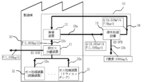
- FIG. 1 is a schematic diagram showing the configuration of an exhaust gas treatment system according to a first embodiment of the present invention.
- solid arrows show piping.
- an exhaust gas treatment system 10 has an exhaust gas separation device (exhaust gas separation section) 11, a detoxification device (exhaust gas treatment facility) 12, and a wastewater treatment facility 13.
- the exhaust gas separation device 11 and the abatement device 12 are installed in a manufacturing building 20.
- the manufacturing building 20 is provided with a plurality of gas treatment devices 21 that discharge a first gas 22a containing a specific substance.
- the abatement device 12 is connected to at least one of the gas treatment devices 21 via the exhaust gas separation device 11.
- the abatement device 12 is connected to a gas treatment device 21 that performs a thin film formation process and a gas treatment device 21 that performs a dry etching process via the exhaust gas separation device 11.
- the thin film formation process may include, for example, a CVD process, but is not limited to this.
- PFC gases such as CF4 , SF6 , and CHF3 are used, and in the thin film formation process, PFC gases such as NF3 , C2F6 , and C3F8 , and semiconductor material gases such as SiH4 , NH3 , SiH2CL2 , and TEOS (tetraethoxysilane) are used.
- gases such as NF3 and CL2 are used for cleaning the inside of the gas processing device.
- the gas processing device 21 discharges a first gas 22a containing these gases. Gases not used in the reaction are discharged together with gases used in the reaction and decomposed (HF, CO2 , decomposition gas, etc.).
- the first gas 22a includes a specific substance.
- the specific substance may include one or both of fluorine (F) and a fluorine compound.
- the specific substance may also include one or both of nitrogen (N) and a nitrogen compound.
- the specific substance is not limited to fluorine and a fluorine compound or nitrogen and a fluorine compound.
- the specific substance may include other components such as a carbon source (C), chlorine (Cl), silicon (Si), and their compounds.
- the specific substance may include at least one component of fluorine, nitrogen, carbon, and silicon and one or both of the compounds of the component.
- the exhaust gas separation device 11 receives the first gas 22a discharged from the gas treatment device (film formation device) 21 and the gas treatment device (dry etching) 21.
- the first gas 22a may contain decomposition products and by-products of the gas discharged from the gas treatment device 21.
- the exhaust gas separation device 11 separates a portion of the specific substance contained in the first gas 22a, and discharges a second gas 22b having a lower content of the specific substance than the first gas 22a.
- the specific substance is assumed to be fluorine and/or its compounds, and the exhaust gas separation device 11 separates and recovers a portion of the fluorine contained in the first gas 22a. In this case, for example, the exhaust gas separation device 11 may recover fluorine as a valuable resource.
- the exhaust gas separation device 11 may have any configuration as long as it can recover a specific substance (here, fluorine) from the first gas 22a.
- Common gas recovery technologies include cryogenic distillation, which separates substances based on boiling point differences, pressure swing adsorption (PSA) and temperature swing adsorption (TSA) methods, which involve repeated adsorption and desorption, and membrane separation methods using gas separation membranes. Any one of these gas recovery technologies, or a combination of these, may be applied to the exhaust gas separation device 11.
- the recovery rate R1 of the specific substance can be set to a theoretically or practically possible value depending on the substance to be recovered and the recovery method.
- the specific substance is fluorine
- the exhaust gas separation device 11 is configured so that the fluorine recovery rate R1 is 50%.
- the fluorine recovery rate R1 indicates the recovery rate relative to the total fluorine load when the first gas 22a is a mixed gas of NF3 , CF4 , SF6 , etc.
- the detoxification device 12 receives the supply water including makeup water 24 from the wastewater treatment facility 13 and the second gas 22b discharged by the exhaust gas separation device 11.
- the detoxification device 12 combusts the second gas 22b to detoxify harmful substances including specific substances, and discharges wastewater in which components derived from the decomposed harmful substances have been dissolved in the supply water.
- fluorine is assumed as the specific substance, and therefore the detoxification device 12 discharges first wastewater 23a in which fluorine has been dissolved in the supply water.
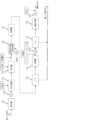
- FIG 2 is a schematic diagram showing one configuration example of the detoxification device 12.
- the solid arrows show a schematic piping through which liquid flows
- the dashed arrows show a schematic piping through which gas flows.
- the detoxification device 12 has a solubilization section 121 and a dissolution section 122.
- the solubilization section 121 processes the second gas 22b to solubilize a specific substance.
- the dissolution section 122 dissolves the specific substance solubilized in the solubilization section 121 into the supply water 25 and discharges the first wastewater 23a.
- the supply water 25 may contain makeup water 24.
- the solubilization section 121 may include a combustion chamber in which a combustion process is performed using, for example, a burner.
- the second gas 22b is supplied to the combustion chamber, and the second gas 22b is decomposed by a thermal decomposition reaction (solubilization of a specific substance).
- the combustion chamber may be cooled with supply water 25 including makeup water 24.
- the water used for cooling is discharged as first wastewater 23a.
- the dissolving section 122 may include, for example, a scrubber that sprays water on the gas.
- the gas in the combustion chamber of the solubilizing section 121 is supplied to the scrubber. In the scrubber, specific substances remaining in the gas are dissolved in water by spraying water (dissolution).
- the water with the specific substances dissolved therein is discharged from the bottom of the scrubber as the first wastewater 23a.
- the solubilization section 121 and the dissolving section 122 may be the same device.
- the combination of the combustion chamber constituting the solubilization section 121 and the scrubber constituting the dissolving section 122 is not limited to the above.
- a scrubber may be provided on each of the inlet and outlet sides of the combustion chamber.
- a smoke washing chamber for spraying water on the gas may be provided between the combustion chamber and the scrubber.
- an existing abatement device that removes a specific substance using, for example, electric heating or plasma may be used as the abatement device 12. Although a detailed description of such abatement device is omitted, a device having a general configuration may be used.
- the wastewater treatment equipment 13 receives the first wastewater 23a discharged by the detoxification equipment 12.
- the wastewater treatment equipment 13 removes specific substances (here, fluorine) from the first wastewater 23a, and supplies the wastewater from which the specific substances have been removed to the detoxification equipment 12 as makeup water 24 for the supply water 25.
- the wastewater treatment equipment 13 further discharges a second wastewater 23b containing the removed specific substances.
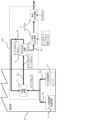
- Fig. 3 shows an example of the wastewater treatment equipment 13.
- the wastewater treatment equipment 13 has a raw water tank 130, a heat exchanger 131, a neutralization tank 132, a biological reaction tank (biological treatment) 133, an intermediate tank 134, an ultrafiltration device (UF) 135, an intermediate tank 136, a reverse osmosis membrane filtration device (RO) 137, and a make-up water tank 138.
- the first wastewater 23a discharged from the detoxification device 12 is stored in the raw water tank 130 as water to be treated.
- the raw water tank 130 and the heat exchanger 131 are connected via a pipe, and a pump 139a is provided on the pipe.
- the heat exchanger 131 and the neutralization tank 132 are connected via a pipe.
- the neutralization tank 132 and the biological reaction tank 133 are connected via a pipe.
- the biological reaction tank 133 and the intermediate tank 134 are connected via a pipe.
- the intermediate tank 134 and the UF 135 are connected via a pipe.
- the UF 135 and the intermediate tank 136 are connected via a pipe.
- the intermediate tank 136 and the RO 137 are connected via a pipe, and a pump 139b is provided on the pipe.
- the RO 137 and the make-up water tank 138 are connected via a pipe.
- a discharge pipe is connected to the make-up water tank 138, and a pump 139c is provided on this pipe.
- the water to be treated stored in the raw water tank 130 can be supplied to the heat exchanger 131, the neutralization tank 132, the biological reaction tank 133, the intermediate tank 134, the UF (ultrafiltration membrane device) 135, the intermediate tank 136, the RO (reverse osmosis membrane device) 137, and the make-up water tank 138 in that order at an appropriate time.
- Heat exchanger 131 performs heat exchange treatment using cooling water.
- Neutralization tank 132 performs neutralization treatment using a neutralizing agent.
- the neutralized water to be treated is supplied to biological reaction tank 133 after nutrients are added.
- Biological reaction tank 133 performs biological treatment.
- Biological reaction tank 133 is provided with a mechanism for aerating the water to be treated (air bubbling mechanism for supplying oxygen required by microorganisms).
- the biologically treated water is supplied to UF 135 via intermediate tank 134.
- UF 135 filters the biologically treated water using multiple UF membranes with fine pores.
- the filtered water of UF 135 is stored in intermediate tank 136, and then a dispersant and slime control agent are added and supplied to RO 137.
- RO 137 further filters the filtered water of UF 135 using multiple RO membranes.
- the filtered water (permeate) of RO 137 is stored in make-up water tank 138.
- the water stored in the make-up water tank 138 is charged with NaClO, discharged as make-up water 24, and supplied to the decontamination device 12.
- the concentrated water separated in the UF 135 and RO 137 is discharged as the second wastewater 23b.
- the exhaust gas separation device 11 separates a portion of the specific substances (components such as fluorine) contained in the first gas 22a, thereby making it possible to reduce the cooling energy required for the abatement device 12. As a result, it is possible to prevent the abatement device 12 and the wastewater treatment facility 13 from becoming large-scale, and to prevent increases in plant costs and operating costs. Below, this effect will be specifically explained using a comparative example.
- (Comparative Example 1) 4 is a schematic diagram showing an exhaust gas treatment system of Comparative Example 1.
- the exhaust gas treatment system 100 of Comparative Example 1 differs from the exhaust gas treatment system 10 of the present embodiment in that it does not include an exhaust gas separation device 11.
- the configuration other than the exhaust gas separation device 11 is basically the same as that of the exhaust gas treatment system 10.
- the first gas 22a discharged from each gas treatment device 21 is directly supplied to the abatement device 12. Therefore, compared to a configuration including the exhaust gas separation device 11, the amount of harmful substances to be abated (or decomposed) is greater, and accordingly the amount of heat generated by the abatement device 12 increases, and the amount of supply water 25 required for cooling increases.
- the amount of the first wastewater 23a from the abatement device 12 increases, and the scale of the drainage equipment and recovery equipment becomes larger, resulting in increased plant costs and operating costs.
- fluorine (F) is a specific substance contained in the exhaust gas.
- the amount of fluorine in the first gas 22a supplied to the detoxification device 12 per day is assumed to be, for example, 2,000 kg/d.
- the thermal energy required to treat 2,000 kg/d of fluorine is consumed, and the amount of supply water 25 corresponding to the amount of heat generated is used.
- the amount of discharge of the first wastewater 23a discharged by the detoxification device 12 per day is assumed to be 20,000 m 3 /d.
- the amount of fluorine contained in the first wastewater 23a per day is 2,000 kg/d.
- the first wastewater 23a also contains components other than fluorine.
- the F concentration of the second wastewater 23b is, for example, 2,000 mg/L.
- the stage flue gas separation device 11 recovers a part of the fluorine contained in the first gas 22a.
- the fluorine recovery rate R1 is 50%, if it is assumed that the amount of fluorine in the first gas 22a per day is 2,000 kg/d, the amount of fluorine in the second gas 22b supplied to the detoxification device 12 per day is 1,000 kg/d.
- the thermal energy required to treat 1,000 kg/d of fluorine is consumed, and the amount of the supply water 25 corresponding to the amount of heat generated is used.
- the amount of this supply water 25 can be reduced compared to Comparative Example 1.
- the amount of the first wastewater 23a discharged per day from the detoxification device 12 can be reduced to 15,000 m 3 /d compared to 20,000 m 3 /d in Comparative Example 1.
- the exhaust gas treatment system 10 of this embodiment it is possible to reduce the amount of the first wastewater 23a discharged by the detoxification device 12 and the amount of fluorine contained in the first wastewater 23a, compared to Comparative Example 1.
- This allows the scale of the detoxification device 12 and the wastewater treatment equipment 13 to be reduced, and plant costs and operating costs to be reduced.
- the reduction in plant costs includes the reduction in construction costs of the plant equipment and the reduction in installation space due to the reduction in scale.
- the operating costs include the energy costs related to operation, the costs of chemicals such as neutralizing agents required to recover specific decomposed substances (components such as fluorine), and the costs of treating waste such as sludge.
- the reduction in operating costs includes the reduction in the amount of chemicals input and the reduction in energy costs (power consumption).
- the amount of the first wastewater 23a discharged by the decomposition device 12 and the amount of fluorine contained in the first wastewater 23a can be reduced, so that even if the amount of harmful substances to be decomposed (or decomposed) increases with an increase in the amount of exhaust gas, the increase in the energy consumption and heat generation of the decomposition device 12, the increase in the amount of make-up water for cooling, and the amount of make-up water required to dissolve the components derived from harmful substances can be suppressed.
- the increase in the amount of wastewater and the load of the decomposition device 12 and the increase in the scale of the wastewater treatment facility 13 can be suppressed, and the increase in plant costs and operating costs can be suppressed.
- the decontamination device 12 shown in FIG. 2 by reducing the supply amount and load of the second gas 22b, it is possible to reduce energy such as fuel and electricity for the burner of the solubilization section 121.
- energy such as fuel and electricity for the burner of the solubilization section 121.
- the supply amount (required amount) of the supply water 25 it is possible to reduce/downsize the scale/capacity of the supply equipment such as piping/feedwater pumps for supplying the supply water 25 to the dissolution section 122.
- the flow rate of the second gas 22b it is possible to reduce the scale of the solubilization section 121 and associated equipment, the scale of the dissolution section 122 and associated equipment, and the scale of the supply equipment such as piping/feedwater pumps for draining the first drainage water 23a.
- the reduction in the amount of the first wastewater 23a makes it possible to reduce the scale of each of the raw water tank 130, the heat exchanger 131, the neutralization tank 132, the biological reaction tank 133, the intermediate tank 134, the UF 135, the intermediate tank 136, the RO 137, and the make-up water tank 138, and also makes it possible to reduce the scale of the piping connecting these.
- the volume of the neutralization tank 132 is 209 m3 and the volume of the biological reaction tank 133 is 834 m3
- the volume of the neutralization tank 132 can be reduced to 157 m3 and the volume of the biological reaction tank 133 can be reduced to 625 m3 .
- the amount of cooling water, neutralizing agent, nutrients, dispersants, slime control agents, and NaCLO can be reduced by reducing the amount of water discharged from the first wastewater 23a.
- the amount of TOC (total organic carbon), which is a component contained in the first wastewater 23a, can be reduced, allowing the scale of the biological reaction tank 133 to be reduced.
- the UF 135 in Comparative Example 1 is provided with 223 UF membranes
- the exhaust gas treatment system 10 of this embodiment it is possible to reduce the number of UF membranes in the UF 135 to 150.
- the reduction in the load of the components (ions) of the second wastewater 23b makes it possible to reduce the number of RO membranes, thereby enabling a reduction in the scale of the RO 137.
- the RO 137 in Comparative Example 1 is provided with 1012 RO membranes, then in the exhaust gas treatment system 10 of this embodiment, the number of RO membranes in the RO 137 can be reduced to 655.
- the water recovery rate R2 of the wastewater treatment facility 13 can be improved as compared to Comparative Example 1.
- the water recovery rate R2 of the wastewater treatment facility 13 may be rate-limiting due to CaF2 scale on the RO membrane concentration side, and when the fluorine concentration on the RO membrane concentration side is the same as that of 2000 mg/L, the water recovery rate R2 is 95% in Comparative Example 1, whereas it is 97% in this embodiment.
- the water recovery rate R2 of the wastewater treatment facility 13 varies depending on the fluorine recovery rate R1 of the flue gas separation device 11.
- Second Embodiment 5 is a schematic diagram showing the configuration of an exhaust gas treatment system according to a second embodiment of the present invention.
- the exhaust gas treatment system 10A of this embodiment differs from the first embodiment in that it has a water treatment device 16.
- the exhaust gas separation device 11, the abatement device 12, and the wastewater treatment facility 13 are the same as those of the first embodiment, so detailed descriptions of these configurations will be omitted here.
- the water treatment device 16 receives the second wastewater 23b discharged by the wastewater treatment facility 13 and performs water treatment to remove specific substances from the second wastewater 23b.
- the specific substance is assumed to be fluorine, and the water treatment device 16 has a fluorine-based wastewater device 14 and a total wastewater device 15.
- the fluorine-based wastewater apparatus 14 receives the second wastewater 23b, and coagulates and precipitates the fluorine contained in the second wastewater 23b.
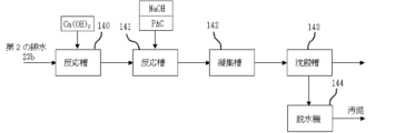
- Fig. 6 shows a specific configuration of the fluorine-based wastewater apparatus 14.
- the fluorine-based wastewater apparatus 14 has reaction tanks 140, 141, a coagulation tank 142, a sedimentation tank 143, and a dehydrator 144.
- the reaction tank 140 and the reaction tank 141 are communicated with each other via a pipe.
- the reaction tank 141 and the coagulation tank 142 are communicated with each other via a pipe.
- the coagulation tank 142 and the sedimentation tank 143 are communicated with each other via a pipe.
- the sedimentation tank 143 and the dehydrator 144 are communicated with each other via a pipe.
- the second wastewater 23b discharged from the wastewater treatment facility 13 is stored in the reaction tank 140.
- Ca(OH) 2 calcium hydroxide
- the water to be treated to which calcium hydroxide has been added is stored in the reaction tank 141.
- PAC polyaluminum chloride
- NaOH sodium hydroxide
- PAC is a flocculant that flocculates and makes it easier for suspended solids contained in the water to be treated to precipitate.
- NaOH is an alkaline agent for adjusting the pH of the water to be treated.
- the water stored in the reaction tank 141 is supplied to a settling tank 143 via a coagulation tank 142.
- a coagulation tank 142 In the coagulation tank 142, turbid matter contained in the water to be treated coagulates, and tiny lumps of flocs are precipitated.
- the settling tank 143 In the settling tank 143, the flocs settle.
- the sediments are supplied to a dehydrator 144, and the water to be treated from which the sediments have been removed is supplied as wastewater to the total wastewater system 15. In the dehydrator 144, the sediments are dehydrated and discharged as sludge.
- a crystallization reaction apparatus for obtaining calcium fluoride crystals as disclosed in Japanese Patent No. 5650164 may be used, and the fluorine-based drainage apparatus 14 is not limited to these methods.
- the total wastewater treatment system 15 receives the wastewater discharged from the fluorine-based wastewater treatment system 14 and performs neutralization treatment.
- Fig. 7 shows a specific configuration of the total wastewater treatment system 15. As shown in Fig. 7, the total wastewater treatment system 15 has a reaction tank 150, a coagulation tank 151, and a flotation separation tank 152. The reaction tank 150 and the coagulation tank 151 are connected via piping. The coagulation tank 151 and the flotation separation tank 152 are connected via piping. Wastewater discharged from the settling tank 143 of the fluorine-based wastewater treatment device 14 is stored in the reaction tank 150. In the reaction tank 150, PAC and NaOH are added.
- the stored water in the reaction tank 150 is supplied to the flotation separation tank 152 via the coagulation tank 151.
- the flotation separation tank 152 is a solid-liquid separation tank.
- pressurized water in which gas is pressurized and dissolved is injected from the bottom of the tank, and air bubbles are attached to the flocs to give them buoyancy, thereby causing them to float and separate.
- Clean water in the bottom of the stored water in the flotation separation tank 152 is discharged as flotation separation treated water.
- the flotation separation treated water can be discharged, for example, into rivers or the ocean, or can be reused as recovered water.
- the exhaust gas separation device 11 recovers a portion of the specific substance contained in the first gas 22a, thereby simultaneously achieving a reduction in the cooling energy required for the abatement device 12 and a reduction in the treatment load of the specific substance (here, fluorine) in the water treatment device 16.
- the scale of the equipment for the water treatment device 16 can be reduced, and plant costs and operating costs can be reduced.
- the amount of sludge generated by fluorine coagulation and precipitation can be reduced. Below, this effect will be specifically described with reference to a comparative example.
- (Comparative Example 2) 8 is a schematic diagram showing an exhaust gas treatment system of Comparative Example 2.
- the exhaust gas treatment system 100A of Comparative Example 2 differs from the exhaust gas treatment system 10A of the present embodiment in that it does not include an exhaust gas separation device 11.
- the configuration other than the exhaust gas separation device 11 is basically the same as that of the exhaust gas treatment system 10A.
- the daily discharge amount of the second wastewater 23b discharged from the wastewater treatment facility 13 is assumed to be, for example, 1,000 m3 /d.
- the daily amount of fluorine contained in the second wastewater 23b is 2,000 kg/d.
- the fluorine-based wastewater treatment device 14 subjects 2,000 kg/d of fluorine to coagulation and sedimentation treatment, and removes it as 8.4 tons of sludge material.
- the daily discharge amount of wastewater discharged from the fluorine-based wastewater treatment device 14 is assumed to be 880 m3 /d.
- the amount of wastewater treated by the total wastewater treatment device 15 is assumed to be 880 m3 /d.
- the amount of second wastewater 23b discharged per day from the wastewater treatment facility 13 can be reduced from 1,000 m 3 /d in Comparative Example 2 to 500 m 3 /d.
- the amount of fluorine contained in the second wastewater 23b per day can be reduced from 2,000 kg/d in Comparative Example 2 to 1,000 kg/d.
- the fluorine-based wastewater treatment device 14 performs coagulation and sedimentation treatment of 1,000 kg/d of fluorine, and as a result, the amount of sludge can be reduced from 8.4 t in Comparative Example 2 to 4.2 t.
- the amount of wastewater discharged per day from the fluorine-based wastewater treatment device 14 can be reduced from 880 m 3 /d in Comparative Example 2 to 440 m 3 /d, and the amount of wastewater treated by the total wastewater treatment device 15 can also be reduced from 880 m 3 /d in Comparative Example 2 to 440 m 3 /d.
- the amount of fluorine treated by the fluorine-based wastewater treatment device 14 can be halved compared to Comparative Example 2. Therefore, the scale of the fluorine-based wastewater treatment device 14 can be reduced, and the amount of chemicals required for the coagulation and sedimentation treatment can be reduced.
- the volume of the reaction tank 140 can be reduced to 6 m3 , the volume of the reaction tank 141 to 6 m3 , the volume of the coagulation tank 142 to 2 m3 , the area of the settling tank 143 to 2 m2 , and the membrane area of the dehydrator 144 to 28 m2 .
- plant costs can be reduced by approximately 50%.
- the input amount of Ca(OH) 2 when the input amount of Ca(OH) 2 is 4,200 kg/d, the input amount of PAC is 300 kg/d, and the input amount of NaOH (caustic soda) is 163 kg/d, in the exhaust gas treatment system 10A of this embodiment, the input amount of Ca(OH) 2 can be reduced to 2,100 kg/d, the input amount of PAC to 151 kg/d, and the input amount of NaOH to 82 kg/d. 7, the reduction in the amount of water and the amount of fluorine in the second wastewater 23b allows the scale of each of the reaction tank 150, the coagulation tank 151, and the flotation separation tank 152 to be reduced, and the scale of the piping connecting these tanks can also be reduced.
- the volume of the reaction tank 150 can be reduced to 5 m3 , the volume of the coagulation tank 151 to 2 m3 , and the area of the flotation separation tank 152 to 1 m2 .
- the plant cost can be reduced by about 50%.
- the PAC input amount when the PAC input amount is 264 kg/d and the NaOH input amount is 143 kg/d, in the exhaust gas treatment system 10A of this embodiment, the PAC input amount can be reduced to 133 kg/d and the NaOH input amount can be reduced to 72 kg/d.
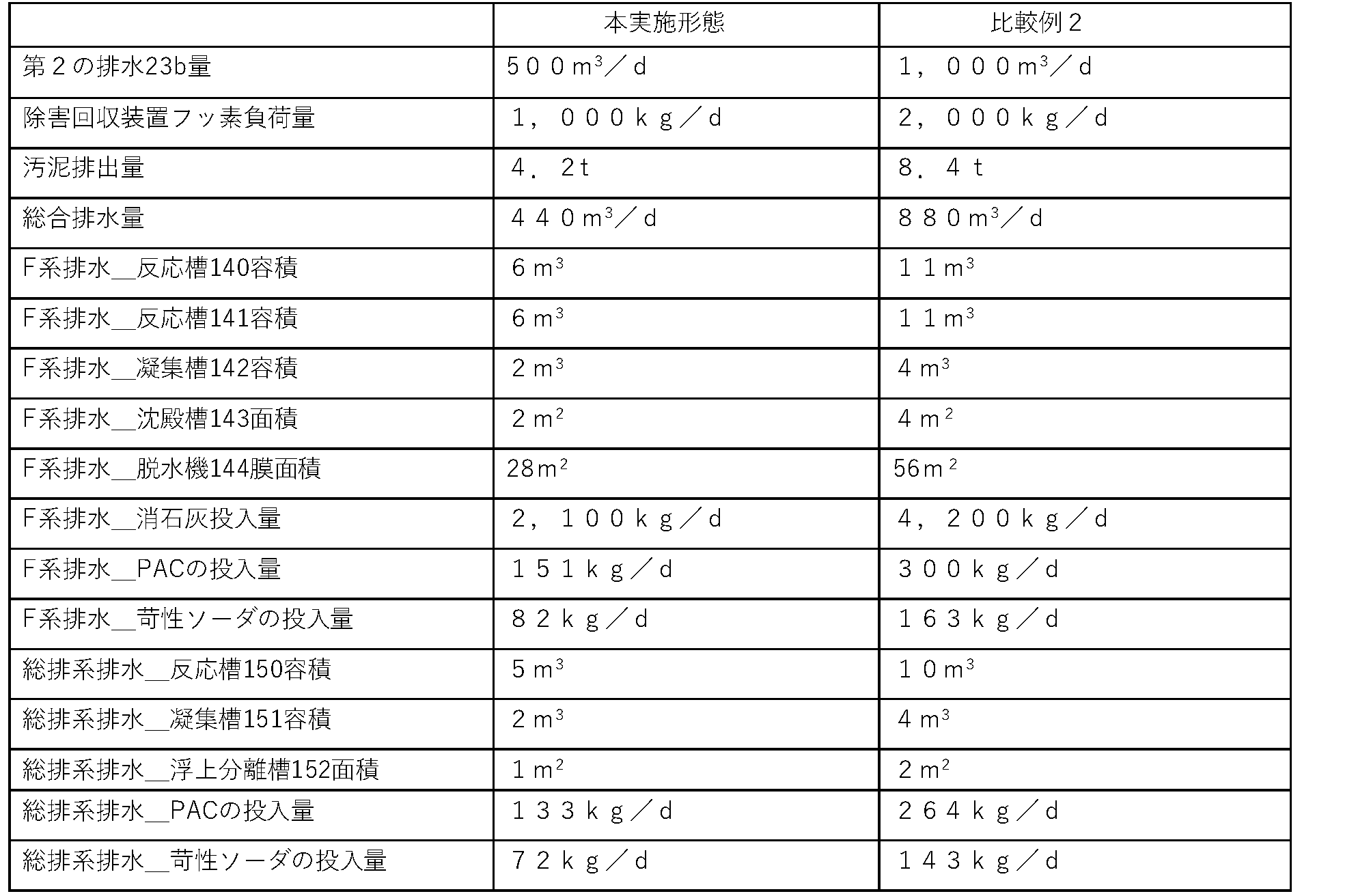
- Table 2 shows the results of a comparison between this embodiment and Comparative Example 2.
- each component of the exhaust gas treatment system 10 (10A) can be modified as appropriate without interfering with the action and effect described in each embodiment.
- the decontamination device 12 and the gas treatment device 21 are arranged in any one of a one-to-one, one-to-many, many-to-one, and many-to-many connection configurations, or in a combination of two or more connection configurations, and the exhaust gas separation device 11 may be incorporated in at least one of the gas treatment devices 21.
- Fig. 9 is a schematic diagram for explaining the connection between the abatement device 12 and the gas treatment device 21.
- the solid arrows show schematic piping through which gas passes, and one solid line may show either a single pipe or multiple pipes.
- the decontamination device 12 and the gas treatment device (film forming device) 21 are arranged in a many-to-many connection form, and the decontamination device 12 and the gas treatment device (dry etching) 21 are arranged in a many-to-many connection form.
- the exhaust gas separation device 11 may be provided anywhere in the communication pipe connecting the decontamination device 12 and the gas treatment device (film forming device) 21.
- the exhaust gas separation device 11 may be provided for each gas treatment device (film forming device) 21 or each decontamination device 12, or may be provided in a collective section to which two or more gas treatment devices (film forming devices) 21 are connected, or in a collective section to which two or more decontamination devices 12 are connected.
- the exhaust gas separation device 11 may be provided anywhere in the communication pipe connecting the decontamination device 12 and the gas treatment device (dry etching) 21.
- the exhaust gas separation device 11 may be provided for each gas treatment device (dry etching) 21, or may be provided in a collective portion where two or more gas treatment devices (dry etching) 21 are connected.
- the decontamination device 12 and the gas treatment device (film formation device) 21 are arranged in a one-to-one connection configuration, and the decontamination device 12 and the gas treatment device (dry etching) 21 are arranged in a one-to-one connection configuration.
- the exhaust gas separation device 11 may be provided for at least one gas treatment device (film formation device) 21.
- the exhaust gas separation device 11 may be provided for at least one gas treatment device (dry etching) 21.
- the decontamination device 12 and the gas treatment device (film forming device) 21 are arranged in a many-to-one connection configuration, and the decontamination device 12 and the gas treatment device (dry etching) 21 are arranged in a many-to-one connection configuration.
- the exhaust gas separation device 11 may be provided anywhere in the communication pipe connecting the decontamination device 12 and the gas treatment device (film forming device) 21.
- the exhaust gas separation device 11 may be provided for each decontamination device 12, or may be provided in a collective section where two or more decontamination devices 12 are connected.
- the exhaust gas separation device 11 may be provided anywhere in the communication pipe connecting the decontamination device 12 and the gas treatment device (dry etching) 21.
- the exhaust gas separation device 11 may be provided for each decontamination device 12, or may be provided in a collective section where two or more decontamination devices 12 are connected.
- the decontamination device 12 and the gas treatment device (film formation device) 21 may be arranged in a one-to-many connection configuration.
- the decontamination device 12 and the gas treatment device (dry etching) 21 may be arranged in a one-to-many connection configuration.
- the exhaust gas separation device 11 may be provided for at least one gas treatment device 21.
- the connection between the decontamination device 12 and the gas treatment device (film formation device) 21 and the gas treatment device (dry etching device) 21 may be a combination of two or more of the four connection configurations of one-to-one, one-to-many, many-to-one, and many-to-many.
- the exhaust gas separation device 11 may be provided for at least one of the gas treatment devices 21.
- the exhaust gas separation device 11 may be incorporated in at least one gas treatment device 21 .
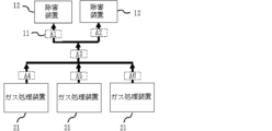
- Fig. 10 is a schematic diagram showing an example of the arrangement of the exhaust gas separation device 11.
- solid arrows are schematic diagrams showing pipes through which gas passes, and one solid line may show a single pipe or may show a plurality of pipes.
- two abatement devices 12 and three gas treatment devices 21 are connected in a multiple-to-multiple configuration.
- a film forming device or a dry etching device can be used as the gas treatment device 21.
- Arrangement positions A1 to A6 indicate positions where the exhaust gas separation device 11 can be arranged.
- Arrangement positions A1 and A2 indicate arrangement of two abatement devices 12 on the gas supply pipes.
- Arrangement position A3 indicates arrangement at a joint of pipes from each gas treatment device 21.
- Arrangement positions A4 to A6 indicate arrangement on pipes from each gas treatment device 21.
- the exhaust gas separation device 11 may be provided at any of the arrangement positions A1 to A6.
- the exhaust gas separation device 11 may also be provided at two or more of the arrangement positions A4 to A6. Furthermore, the exhaust gas separation device 11 may be provided at both the arrangement positions A1 and A2.
- Fig. 11 is a schematic diagram showing another example of the arrangement of the exhaust gas separation device 11.
- solid arrows typically indicate pipes through which gas passes.
- the arrangement positions A1 to A9 of the exhaust gas separation device 11 are shown relative to one gas treatment device (film formation device) 21.
- the gas treatment device (film formation device) 21 has four chambers 21a.
- a pump 30 is provided in the piping on the discharge side of each chamber 21a.
- the piping on the discharge side of each pump 30 merges into one.
- Arrangement position A1 indicates the arrangement at the junction of the piping from each pump.
- Arrangement positions A2 to A5 indicate the arrangement on the piping on the discharge side of each pump 30.
- FIG. 12 is a schematic diagram showing yet another example of the arrangement of the exhaust gas separation device 11.
- solid arrows are schematic diagrams showing pipes through which gas passes.
- the chamber 21a, the pump 30, and the pipes are the same as those shown in FIG. 11.
- a valve 31 is provided in the pipes from each pump 30, and two pipes are provided from before and after the valve 31 toward the exhaust gas separation device 11.
- One of the two pipes is a supply line, and the other is a discharge line.
- a valve 32 is provided in the supply line, and a valve 33 is provided in the discharge line.
- Each supply line is connected to one line and connected to the exhaust gas separation device 11.
- Each discharge line is also connected to one line and connected to the exhaust gas separation device 11.
- each chamber 21a can be individually connected to the exhaust gas separation device 11. For example, when a cleaning process is performed for each chamber 21a in sequence, the chamber 21a in which the cleaning process is performed is connected to the exhaust gas separation device 11. This allows efficient recovery (separation) of exhaust gas. Furthermore, according to this arrangement, the amount of exhaust gas is the smallest and the concentration (load) of the gas to be treated can be increased compared to the arrangements shown in Figures 10 and 11, so that the recovery equipment can be made smaller and the recovery efficiency is improved. 12, the path switching unit using the valves 31 to 33 may be provided in at least one of the chambers 21a.
- the number of the chambers 21a is not limited to four. The number of the chambers 21a may be two or more.
- the valve 31 may be normally closed and the valves 32 and 33 may be normally open so that the exhaust gas from each gas treatment device 21 always passes through the exhaust gas separation device 11.
- the valve 31 may be closed and the valves 32 and 33 may be opened so that the exhaust gas from each gas treatment device 21 always passes through the exhaust gas separation device 11 only during a time period when the amount of exhaust gas from each gas treatment device 21 is large.
- the path switching unit using the valves 31 to 33 may be provided in a pipe other than the assembly of the pipes.
- the path switching unit may be provided in at least one of the arrangement positions A1, A2, and A4 to A6 shown in FIG.
- the path switching unit using the valves 31 to 33 can also be applied to the one-to-one connection, one-to-many connection, and many-to-many connection described with reference to Fig. 9.
- a path switching unit using the valves 31 to 33 may be provided for at least one pipe as necessary.
- the piping connecting the gas treatment device 21 and the abatement device 12 can be composed of a regular line and a reserve line.
- a route switching unit using valves 31 to 33 may be provided in each of the regular line and the reserve line.
- a route switching unit is provided at a junction of the piping of the regular lines, and similarly, a route switching unit is provided at a junction of the piping of the reserve lines.
- the regular line is used, and the regular line is connected to the flue gas separation device 11 as necessary.
- the reserve line is used, and the reserve line is connected to the flue gas separation device 11 as necessary.
- a part of the piping connecting the gas treatment device 21 and the abatement device 12 may be a piping structure in which a plurality of pipes are connected in parallel.
- a path switching unit using valves 31 to 33 may be provided for each pipe of the piping structure.
- a collective portion of the pipes from each gas treatment device 21 may be the above-mentioned piping structure, and each pipe of this piping structure may be provided with a path switching unit.
- the exhaust gas separation device 11 in a gas treatment device 21 that contains a large amount of a specific substance in the first gas 22a among the multiple gas treatment devices 21.
- application of this technology makes it possible to reduce the plant costs of the abatement device 12 and the wastewater treatment facility 13, as well as the amount of chemicals and waste generated, and at the same time, it also makes it possible to reduce the amount of CO2 emissions caused by these activities.
- the improvement method of this other embodiment is a method for improving an exhaust gas treatment system including a detoxification device 12 that receives exhaust gas containing a specific substance and makeup water, combusts the exhaust gas to detoxify the specific substance, and discharges wastewater in which the detoxified specific substance has been dissolved in the makeup water, and a wastewater treatment facility 13 that receives the wastewater, removes the specific substance from the wastewater, and recovers the wastewater from which the specific substance has been removed as the makeup water, and includes providing an exhaust gas separation device 11 that receives a first gas 22a containing the specific substance, recovers a portion of the specific substance contained in the first gas 22a, and discharges a second gas 22b, which contains less of the specific substance than the first gas 22a, as the exhaust gas to the detoxification device 12.
- the recovery rate of the specific substance in the exhaust gas separation device 11 is set so that the supply amount per unit time of the specific substance supplied to the detoxification device 12 is less than the treatment amount per unit time of the specific substance treated by the detoxification device 12.
- the supply amount of fluorine is assumed to be 2,000 kg/d, and the maximum fluorine processing amount of the abatement device 12 is assumed to be 1,000 kg/d.
- fluorine recovery rate of the exhaust gas separation device 11 incorporated in the upstream stage of the abatement device 12 is set to 50%, fluorine can be removed by the abatement device 12 without changing the existing equipment.
- the equipment that should be expanded in response to an increase in the supply amount of fluorine can be reduced so that the existing equipment can handle it, or it becomes possible to handle an increase in the load on the production side without increasing the wastewater treatment equipment and/or wastewater equipment.
- an exhaust gas separation unit that receives a first gas containing a specific substance, separates a portion of the specific substance contained in the first gas, and discharges a second gas having a content of the specific substance less than that of the first gas; a solubilizing unit that processes the second gas to solubilize the specific substance; a dissolving section that dissolves the solubilized specific substance in supply water and discharges a first wastewater; a wastewater treatment facility that receives the first wastewater, removes the specific substances from the first wastewater, and recovers the wastewater from which the specific substances have been removed as make-up water for the supply water.
- the wastewater treatment facility is configured to discharge a second wastewater containing the specific substance removed from the first wastewater; 2.
- the first gas is a gas generated in one or both of a thin film formation process and a dry etching process.
- Appendix 4 4. An exhaust gas treatment system according to any one of claims 1 to 3, wherein a decontamination device including the solubilization section and the dissolution section is connected to a gas treatment device that discharges the first gas via the exhaust gas separation section.
- a plurality of the abatement devices and a plurality of the gas treatment devices are arranged, and the plurality of the abatement devices and the plurality of the gas treatment devices are connected in any one of a one-to-one, one-to-many, many-to-one, and many-to-many connection form, or in a combination of two or more connection forms;
- the exhaust gas treatment system described in Appendix 4 wherein the exhaust gas separation unit is incorporated in a piping through which a gas containing the specific substance flows that is provided inside at least one of the multiple gas treatment devices, or in a piping through which a gas containing the specific substance flows that extends from the gas treatment device to the outside.
- Appendix 6 6.
- a method for remodeling an exhaust gas treatment system including: a detoxification device that treats exhaust gas containing specific substances to solubilize the specific substances, dissolves the solubilized specific substances in supply water, and discharges first wastewater; and a wastewater treatment facility that receives the first wastewater, removes the specific substances from the first wastewater, and recovers the wastewater from which the specific substances have been removed as make-up water for the supply water, comprising: A method for modifying an exhaust gas treatment system, comprising providing an exhaust gas separation device that receives a first gas containing the specific substance, separates a portion of the specific substance contained in the first gas, and discharges a second gas, which has a lower content of the specific substance than the first gas, as the exhaust gas to the abatement device.
- Appendix 10 A method for modifying an exhaust gas treatment system as described in Appendix 9, in which the recovery rate of the specific substance in the exhaust gas separation device is set so that the amount of the specific substance supplied per unit time to the decontamination device is less than the amount of the specific substance treated by the decontamination device per unit time.
Landscapes
- Engineering & Computer Science (AREA)
- Chemical & Material Sciences (AREA)
- Environmental & Geological Engineering (AREA)
- Biomedical Technology (AREA)
- Health & Medical Sciences (AREA)
- Analytical Chemistry (AREA)
- General Chemical & Material Sciences (AREA)
- Oil, Petroleum & Natural Gas (AREA)
- Chemical Kinetics & Catalysis (AREA)
- Life Sciences & Earth Sciences (AREA)
- Water Supply & Treatment (AREA)
- Hydrology & Water Resources (AREA)
- Organic Chemistry (AREA)
- Sustainable Development (AREA)
- Treating Waste Gases (AREA)
Abstract
排ガス処理システム10は、特定の物質を含む第1のガス22aを受け、第1のガス22aに含まれる特定の物質の一部を分離し、特定の物質の含有量が第1のガス22aよりも少ない第2のガス22bを排出する排ガス分離装置11と、第2のガス22bを処理して特定の物質を可溶化し、可溶化された特定の物質を供給水に溶け込ませて第1の排水23aを排出する除害装置12と、第1の排水23aを受け、第1の排水23aから特定の物質を取り除き、特定の物質を取り除いた排水を供給水の補給水として回収する排水処理設備13と、を有する。
Description
本発明は、排ガス処理システム、排ガス処理方法および排ガス処理システムの改造方法に関する。
半導体、液晶、LED(Light Emitting Diode)、太陽電池等の製造プロセスでは、パーフルオロ化合物(PFC)ガスをはじめ様々なガスが使用されている。例えば、半導体製造工場では、ドライエッチング工程でCF4、SF6、CHF3などが使用され、CVD(Chemical Vapor Deposition)等の薄膜形成工程でNF3、C2F6、C3F8などが使用され、これらのPFCガスを含む排ガスが生じる。PFCガスは、有害であり、温室効果ガスでもある。
PFCガス等を含む排ガスを処理する設備として、排ガスを燃焼除害等により処理する排ガス処理設備(除害装置)が知られている(例えば、特許文献1等)。更に、排ガス処理設備からの排水を処理して排ガス処理設備に戻す排水処理設備も知られている(例えば、特許文献2等)。
近年、半導体デバイスの微細化あるいは多層化により、半導体製造工程で用いられるガスの量は増加傾向にある。それに伴い、除害(又は分解)すべき有害物質の量も増加する。その結果、排ガス処理設備や排水処理設備の規模が大きくなり、プラントコストや運転コストが増加する。
本発明の目的は、排ガス処理設備や排水処理設備の大規模化を抑制し、プラントコストおよび運転コストの増加を抑制可能な排ガス処理システム、排ガス処理方法、および排ガス処理システムの改善方法を提供することにある。
上記目的を達成するため、本発明の一態様によれば、特定の物質を含む第1のガスを受け、該第1のガスに含まれる前記特定の物質の一部を分離し、前記特定の物質の含有量が前記第1のガスよりも少ない第2のガスを排出する排ガス分離部と、前記第2のガスを処理して前記特定の物質を可溶化する可溶化部と、可溶化された前記特定の物質を供給水に溶け込ませて第1の排水を排出する溶解部と、前記第1の排水を受け、該第1の排水から前記特定の物質を取り除き、前記特定の物質を取り除いた排水を前記供給水の補給水として回収する排水処理設備と、を有する、排ガス処理システムが提供される。
本発明の別の態様によれば、特定の物質を含む第1のガスを受け、該第1のガスに含まれる前記特定の物質の一部を分離し、前記特定の物質の含有量が前記第1のガスよりも少ない第2のガスを排出する工程と、前記第2のガスを処理して前記特定の物質を可溶化する工程と、可溶化された前記特定の物質を供給水に溶け込ませて第1の排水を排出する工程と、前記第1の排水を受け、該第1の排水から前記特定の物質を取り除き、前記特定の物質を取り除いた排水を前記供給水の補給水として回収する工程と、を含む排ガス処理方法が提供される。
本発明のさらに別の態様によれば、特定の物質を含む排ガスを処理して前記特定の物質を可溶化し、可溶化された前記特定の物質を供給水に溶け込ませて第1の排水を排出する除害装置と、前記第1の排水を受け、該第1の排水から前記特定の物質を取り除き、前記特定の物質を取り除いた排水を前記供給水の補給水として回収する排水処理設備とを備える排ガス処理システムの改造方法であって、前記特定の物質を含む第1のガスを受け、該第1のガスに含まれる前記特定の物質の一部を分離し、前記特定の物質の含有量が前記第1のガスよりも少ない第2のガスを前記排ガスとして前記除害装置へ排出する排ガス分離装置を設ける、排ガス処理システムの改造方法が提供される。
本発明によれば、排ガス処理設備や排水処理設備の大規模化を抑制し、プラントコストおよび運転コストの増加を抑制することができる。
以下、図面を参照して本発明の実施形態を詳細に説明する。但し、実施形態に記載されている構成要素はあくまで例示であり、本発明の範囲をそれらに限定する趣旨のものではない。
(第1の実施形態)
図1は、本発明の第1の実施形態による排ガス処理システムの構成を示す模式図である。図1において、実線の矢印は配管を模式的に示したものである。図1を参照すると、排ガス処理システム10は、排ガス分離装置(排ガス分離部)11、除害装置(排ガス処理設備)12、および排水処理設備13を有する。
図1は、本発明の第1の実施形態による排ガス処理システムの構成を示す模式図である。図1において、実線の矢印は配管を模式的に示したものである。図1を参照すると、排ガス処理システム10は、排ガス分離装置(排ガス分離部)11、除害装置(排ガス処理設備)12、および排水処理設備13を有する。
本実施形態では、排ガス分離装置11および除害装置12は、製造棟20に設置されている。製造棟20には、特定の物質を含む第1のガス22aを排出する複数のガス処理装置21が設けられている。除害装置12は、排ガス分離装置11を介して、少なくとも一つのガス処理装置21と連通している。本実施形態では、除害装置12は、排ガス分離装置11を介して、薄膜形成工程を行うガス処理装置21とドライエッチング工程を行うガス処理装置21とに連通している。薄膜形成工程は、例えば、CVD工程を含んでもよいが、これに限定されない。
ドライエッチング工程では、例えば、CF4、SF6、CHF3などのPFCガスが使用され、薄膜形成工程では、例えば、NF3、C2F6、C3F8などのPFCガスや、SiH4やNH3、SiH2CL2、TEOS(テトラエトキシシアン)等の半導体材料ガスが使用される。また、ガス処理装置内のクリーニングのために、NF3やCL2などのガスが使用される。ガス処理装置21は、これらのガスを含む第1のガス22aを排出する。反応に使われなかったガスは、反応で使われ分解したガス(HF、CO2、分解ガス等)と共に排出される。各ガス処理装置21において、第1のガス22aを排出するために、例えば、真空ポンプが用いられることがある。この場合、真空ポンプ以降の設備の保護や、安全上の目的から、多量の窒素(N2)ガスが導入されることがある。ここでは、第1のガス22aは、特定の物質を含む。特定の物質は、フッ素(F)およびフッ素化合物の一方または両方を含んでいてもよい。また、特定の物質は、窒素(N)および窒素化合物の一方または両方を含んでいてもよい。なお、特定の物質は、フッ素およびフッ素化合物や窒素およびフッ素化合物に限定されない。例えば、特定の物質は、炭素源(C)、塩素(Cl)、ケイ素(Si)など、他の成分やその化合物を含んでいてもよい。換言すると、特定の物質は、フッ素、窒素、炭素、およびケイ素のうちの少なくとも1つの成分と該成分の化合物の一方または両方を含んでいてもよい。
排ガス分離装置11は、ガス処理装置(成膜装置)21およびガス処理装置(ドライエッチング)21がそれぞれ排出した第1のガス22aを受ける。第1のガス22aは、ガス処理装置21から排出されたガスの分解物や副生成物を含んでいてもよい。排ガス分離装置11は、第1のガス22aに含まれる特定の物質の一部を分離し、特定の物質の含有量が第1のガス22aよりも少ない第2のガス22bを排出する。本実施形態では、特定の物質としてフッ素および/またはその化合物を想定しており、排ガス分離装置11は、第1のガス22aに含まれるフッ素の一部を分離して回収する。この場合、例えば、排ガス分離装置11は、フッ素を有価物として回収してもよい。
排ガス分離装置11は、第1のガス22aから特定の物質(ここでは、フッ素)を回収できるものであれば、どのような構成であってもよい。一般的なガス回収技術として、沸点差で分離する深冷蒸留法、吸脱着を繰り返す圧力スウィング吸着(PSA)法や温度スウィング吸着(TSA)法、ガス分離膜を使った膜分離法が知られている。これらガス回収技術のいずれか、または組み合わせを排ガス分離装置11に適用してもよい。
排ガス分離装置11において特定の物質を分離して回収する場合、特定の物質の回収率R1は、回収対象物質や回収方法に応じて、原理的または現実的に可能な値に設定することができる。例えば、本実施形態では、特定の物質をフッ素とし、排ガス分離装置11は、フッ素の回収率R1が50%になるように構成されている。ここで、フッ素の回収率R1は、例えば、第1のガス22aがNF3、CF4、SF6などの混合ガスである場合、フッ素負荷全量に対する回収率を示す。
除害装置12は、排水処理設備13からの補給水24を含む供給水と排ガス分離装置11が排出した第2のガス22bとを受ける。除害装置12は、第2のガス22bを燃焼して特定の物質を含む有害物質を除害し、分解された有害物質由来の成分を供給水に溶け込ませた排水を排出する。ここでは、特定の物質としてフッ素を想定しているため、除害装置12は、フッ素を供給水に溶け込ませた第1の排水23aを排出する。
除害装置12の構成を具体的に説明する。図2は、除害装置12の一構成例を示す模式図である。図2において、実線の矢印は液体が流れる配管を模式的に示したものであり、破線の矢印は気体が流れる配管を模式的に示したものである。図2を参照すると、除害装置12は、可溶化部121と溶解部122を有する。可溶化部121は、第2のガス22bを処理して特定の物質を可溶化する。溶解部122は、可溶化部121で可溶化された特定の物質を供給水25に溶け込ませて第1の排水23aを排出する。供給水25は、補給水24を含んでもよい。
可溶化部121は、例えばバーナを用いた燃焼処理が行われる燃焼室を含んでいてもよい。第2のガス22bが燃焼室に供給され、熱分解反応によって第2のガス22bが分解される(特定の物質の可溶化)。この場合、補給水24を含む供給水25で燃焼室を冷却してもよい。冷却に使用した水は、第1の排水23aとして排出される。
溶解部122は、例えばガスに対して散水を行うスクラバーを含んでいてもよい。可溶化部121の燃焼室内のガスがスクラバーに供給される。スクラバー内では、散水により、ガス中に残っている特定の物質が水に溶け込む(溶解)。特定の物質が溶け込んだ水は、第1の排水23aとしてスクラバーの底部から排出される。
溶解部122は、例えばガスに対して散水を行うスクラバーを含んでいてもよい。可溶化部121の燃焼室内のガスがスクラバーに供給される。スクラバー内では、散水により、ガス中に残っている特定の物質が水に溶け込む(溶解)。特定の物質が溶け込んだ水は、第1の排水23aとしてスクラバーの底部から排出される。
なお、可溶化部121と溶解部122は、同一の装置であてもよい。また、可溶化部121を構成する燃焼室と溶解部122を構成するスクラバーとの組み合わせは上述したものに限定されない。例えば、燃焼室の入口側と出口側にそれぞれスクラバーを設けてもよい。また、燃焼室とスクラバーの間にガスに対して散水を行う洗煙室を設けてもよい。
また、除害装置12として、例えば、電気加熱やプラズマを用いて特定の物質を取り除く既存の除害装置を用いてもよい。このような除害装置の詳細な説明は省略するが、一般的な構成の装置を使用することができる。
また、除害装置12として、例えば、電気加熱やプラズマを用いて特定の物質を取り除く既存の除害装置を用いてもよい。このような除害装置の詳細な説明は省略するが、一般的な構成の装置を使用することができる。
排水処理設備13は、除害装置12が排出した第1の排水23aを受ける。排水処理設備13は、第1の排水23aから特定の物質(ここでは、フッ素)を取り除き、特定の物質を取り除いた排水を供給水25の補給水24として除害装置12に供給する。排水処理設備13は、さらに、取り除いた特定の物質を含む第2の排水23bを排出する。
図3に、排水処理設備13の一例を示す。図3に示すように、排水処理設備13は、原水槽130、熱交換器131、中和槽132、生物反応槽(生物処理)133、中間槽134、限外濾過装置(UF)135、中間槽136、逆浸透膜濾過装置(RO)137、および補給水槽138を有する。
除害装置12が排出した第1の排水23aは、被処理水として原水槽130に貯留される。原水槽130と熱交換器131は、配管を介して連通しており、この配管にポンプ139aが設けられている。熱交換器131と中和槽132は、配管を介して連通している。中和槽132と生物反応槽133は、配管を介して連通している。生物反応槽133と中間槽134は、配管を介して連通している。中間槽134とUF135は、配管を介して連通している。UF135と中間槽136は、配管を介して連通している。中間槽136とRO137は、配管を介して連通しており、この配管にポンプ139bが設けられている。RO137と補給水槽138は、配管を介して連通している。補給水槽138には、排出用の配管が接続されており、この配管にポンプ139cが設けられている。ポンプ139a~139cを制御することで、原水槽130に貯留した被処理水を、適切なタイミングで、熱交換器131、中和槽132、生物反応槽133、中間槽134、UF(限外ろ過膜装置)135、中間槽136、RO(逆浸透膜装置)137、および補給水槽138に順に供給することができる。
除害装置12が排出した第1の排水23aは、被処理水として原水槽130に貯留される。原水槽130と熱交換器131は、配管を介して連通しており、この配管にポンプ139aが設けられている。熱交換器131と中和槽132は、配管を介して連通している。中和槽132と生物反応槽133は、配管を介して連通している。生物反応槽133と中間槽134は、配管を介して連通している。中間槽134とUF135は、配管を介して連通している。UF135と中間槽136は、配管を介して連通している。中間槽136とRO137は、配管を介して連通しており、この配管にポンプ139bが設けられている。RO137と補給水槽138は、配管を介して連通している。補給水槽138には、排出用の配管が接続されており、この配管にポンプ139cが設けられている。ポンプ139a~139cを制御することで、原水槽130に貯留した被処理水を、適切なタイミングで、熱交換器131、中和槽132、生物反応槽133、中間槽134、UF(限外ろ過膜装置)135、中間槽136、RO(逆浸透膜装置)137、および補給水槽138に順に供給することができる。
熱交換器131は、冷却水を用いた熱交換処理を行う。中和槽132は、中和剤を用いた中和処理を行う。中和した被処理水は、栄養剤を投入した後に、生物反応槽133に供給される。生物反応槽133は、生物処理を行う。生物反応槽133には、被処理水をばっ気する機構(微生物に必要な酸素を供給するためのエアバブリング機構)が設けられている。生物処理水は、中間槽134を介してUF135に供給される。UF135は、微細孔径を有する複数本のUF膜を用いて生物処理水を濾過する。UF135の濾過処理水は、中間槽136に貯留し、その後、分散剤およびスライムコントロール剤が投入されてRO137に供給される。RO137は、複数本のRO膜を用いてUF135の濾過処理水をさらに濾過する。RO137の濾過処理水(透過水)は、補給水槽138に貯留される。この補給水槽138の貯留水は、NaCLOが投入され、補給水24として排出されて除害装置12に供給される。UF135およびRO137で分離された濃縮水は、第2の排水23bとして排出される。
上述した本実施形態の排ガス処理システム10によれば、排ガス分離装置11が第1のガス22aに含まれる特定の物質(フッ素等の成分)の一部を分離することで、除害装置12に要求される冷却エネルギーの低減を図ることができる。その結果、除害装置12や排水処理設備13の大規模化を抑制し、プラントコストおよび運転コストの増加を抑制することができる。以下に、この作用効果について、比較例を挙げて具体的に説明する。
(比較例1)
図4は、比較例1の排ガス処理システムを示す模式図である。比較例1の排ガス処理システム100は、排ガス分離装置11を備えていない点で、本実施形態の排ガス処理システム10と異なる。排ガス処理システム100において、排ガス分離装置11以外の構成は基本的に排ガス処理システム10と同じである。
排ガス処理システム100では、各ガス処理装置21が排出した第1のガス22aは、そのまま除害装置12に供給される。このため、排ガス分離装置11を備える構成に比べて、除害(又は分解)すべき有害物質の量が多くなり、それに伴って除害装置12の発熱量が増大し、冷却に必要な供給水25の量が増大する。その結果、除害装置12の第1の排水23aの量が増大し、排水設備や回収設備の規模が大きくなり、プラントコストおよび運転コストが増大する。
図4は、比較例1の排ガス処理システムを示す模式図である。比較例1の排ガス処理システム100は、排ガス分離装置11を備えていない点で、本実施形態の排ガス処理システム10と異なる。排ガス処理システム100において、排ガス分離装置11以外の構成は基本的に排ガス処理システム10と同じである。
排ガス処理システム100では、各ガス処理装置21が排出した第1のガス22aは、そのまま除害装置12に供給される。このため、排ガス分離装置11を備える構成に比べて、除害(又は分解)すべき有害物質の量が多くなり、それに伴って除害装置12の発熱量が増大し、冷却に必要な供給水25の量が増大する。その結果、除害装置12の第1の排水23aの量が増大し、排水設備や回収設備の規模が大きくなり、プラントコストおよび運転コストが増大する。
排ガスに含まれる特定の物質としてフッ素(F)を想定し、上記問題を具体的に説明する。排ガス処理システム100において、除害装置12に供給される第1のガス22aの一日当たりのフッ素の量を、例えば2,000kg/dと仮定する。除害装置12では、2,000kg/dのフッ素を処理するのに必要な熱エネルギーが消費され、その発熱量に応じた量の供給水25が使用される。除害装置12が排出する第1の排水23aの一日当たりの排出量を20,000m3/dと仮定する。第1の排水23aに含まれる一日当たりのフッ素の量は、2,000kg/dである。なお、第1の排水23aには、フッ素以外の成分も含まれている。第2の排水23bのF濃度は、例えば、2,000mg/Lである。
これに対して、本実施形態の排ガス処理システム10では、段落排ガス分離装置11が、第1のガス22aに含まれるフッ素の一部を回収する。ここでは、フッ素の回収率R1は50%であるため、第1のガス22aの一日当たりのフッ素の量が2,000kg/dであると仮定すると、除害装置12に供給される第2のガス22bの一日当たりのフッ素の量は1,000kg/dとなる。除害装置12では、1,000kg/dのフッ素を処理するのに必要な熱エネルギーが消費され、その発熱量に応じた量の供給水25が使用される。この供給水25の量は、比較例1に比べて削減することができる。具体的には、除害装置12が排出する第1の排水23aの一日当たりの排出量は、比較例1の20,000m3/dに対して、15,000m3/dに削減することができる。
上記のように、本実施形態の排ガス処理システム10によれば、比較例1と比較して、除害装置12が排出する第1の排水23aの排出量およびその第1の排水23aに含まれるフッ素の量を低減することできる。これにより、除害装置12および排水処理設備13の規模を縮小し、プラントコストや運転コストを削減することができる。ここで、プラントコストの削減は、プラント設備の建設コストの削減や規模縮小による設置スペース縮小を含む。また、運転コストは、運転に関わるエネルギーコストや、分解された特定の物質(フッ素等の成分)を回収するために必要な中和剤などの薬品のコスト、汚泥などの廃棄物処理コストを含む。運転コストの削減は、薬品の投入量の削減やエネルギーコスト(電力消費量)の削減を含む。
また、排ガス量の増加に伴い除害(又は分解)すべき有害物質の量が増加すると、除害装置のエネルギー消費量、発熱量が増大し、冷却する為の補給水、及び有害物質由来の成分を溶け込ませるに必要な補給水の量が増大する。その結果、除害装置の排水量及び負荷量が増大して、排水処理設備の規模が大きくなり、プラントコストや運転コストが増大する。本実施形態の排ガス処理システム10によれば、除害装置12が排出する第1の排水23aの排出量およびその第1の排水23aに含まれるフッ素の量を低減することできるため、排ガス量の増加に伴い除害(又は分解)すべき有害物質の量が増加しても、除害装置12のエネルギー消費量、発熱量の増大、冷却する為の補給水、及び有害物質由来の成分を溶け込ませるに必要な補給水の量の増大を抑制することができる。その結果、除害装置12の排水量及び負荷量の増大、排水処理設備13の大規模化を抑制し、プラントコストや運転コストの増大を抑制することができる。
具体的には、図2に示した除害装置12において、第2のガス22bの供給量低下と負荷量低下により、可溶化部121のバーナの燃料や電力等のエネルギー削減が可能である。供給水25の供給量(必要量)の低下により、供給水25を溶解部122に供給するための配管/給水ポンプ等の供給設備の規模/容量を削減/縮小することが可能である。第2のガス22bの流量低下により、可溶化部121及び付帯設備の規模縮小、溶解部122及び付帯設備の規模縮小、第1の排水23aの排水用の配管/給水ポンプ等の供給設備の規模縮小が可能である。
また、図3に示した排水処理設備13において、第1の排水23aの水量減少により、原水槽130、熱交換器131、中和槽132、生物反応槽133、中間槽134、UF135、中間槽136、RO137、および補給水槽138のそれぞれの規模縮小が可能であり、これらを接続する配管の規模縮小も可能である。例えば、比較例1において、中和槽132の容積を209m3、生物反応槽133の容積を834m3とすると、本実施形態の排ガス処理システム10では、中和槽132の容積を157m3、生物反応槽133の容積を625m3に削減することができる。
また、第1の排水23aの水量減少により、冷却水、中和剤、栄養剤、分散剤、スライムコントロール剤、およびNaCLOの投入量(必要量)を削減することが可能である。さらに、第1の排水23aに含まれる成分であるTOC(全有機体炭素)負荷低下により、生物反応槽133の規模縮小が可能である。
また、第1の排水23aの水量減少により、冷却水、中和剤、栄養剤、分散剤、スライムコントロール剤、およびNaCLOの投入量(必要量)を削減することが可能である。さらに、第1の排水23aに含まれる成分であるTOC(全有機体炭素)負荷低下により、生物反応槽133の規模縮小が可能である。
さらに、第1の排水23aに含まれる成分であるシリカ(珪酸)や固形物の負荷低下により、UF膜の本数を削減することができ、UF135の規模縮小が可能である。例えば、比較例1において、UF135が223本のUF膜を備えるとすると、本実施形態の排ガス処理システム10では、UF135のUF膜の本数を150本に削減することが可能である。
さらに、第2の排水23bの成分(イオン類)の負荷低下により、RO膜の本数を削減することができ、RO137の規模縮小が可能である。例えば、比較例1において、RO137が1012本のRO膜を備えるとすると、本実施形態の排ガス処理システム10では、RO137のRO膜の本数を655本に削減することが可能である。
さらに、第2の排水23bの成分(イオン類)の負荷低下により、RO膜の本数を削減することができ、RO137の規模縮小が可能である。例えば、比較例1において、RO137が1012本のRO膜を備えるとすると、本実施形態の排ガス処理システム10では、RO137のRO膜の本数を655本に削減することが可能である。
また、本実施形態の排ガス処理システム10によれば、比較例1と比較して、排水処理設備13の水回収率R2を改善することができる。例えば、排水処理設備13の水回収率R2は、RO膜濃縮側のCaF2スケールが律速となる可能性があり、RO膜濃縮側のフッ素濃度を同じ2000mg/Lとした場合において、比較例1では95%になるのに対して、本実施形態では97%となる。
なお、排水処理設備13の水回収率R2は、排ガス分離装置11のフッ素の回収率R1に応じて変化する。具体的には、除害装置12からの排水量が一定の場合(排水処理設備13への供給水量が一定の場合)、フッ素の回収率R1が高いほど、水回収率R2を高くすることができる。例えば、フッ素の回収率R1を70%とすると、水回収率R2を98%にすることができる。
表1に、本実施形態(フッ素の回収率R1:50%/70%)と比較例1との比較結果を示す。

なお、排水処理設備13の水回収率R2は、排ガス分離装置11のフッ素の回収率R1に応じて変化する。具体的には、除害装置12からの排水量が一定の場合(排水処理設備13への供給水量が一定の場合)、フッ素の回収率R1が高いほど、水回収率R2を高くすることができる。例えば、フッ素の回収率R1を70%とすると、水回収率R2を98%にすることができる。
表1に、本実施形態(フッ素の回収率R1:50%/70%)と比較例1との比較結果を示す。
(第2の実施形態)
図5は、本発明の第2の実施形態による排ガス処理システムの構成を示す模式図である。本実施形態の排ガス処理システム10Aは、水処理装置16を有する点で、第1の実施形態と異なる。排ガス分離装置11、除害装置12、および排水処理設備13は、第1の実施形態と同じであるため、ここでは、これらの構成の詳細な説明は省略する。
図5は、本発明の第2の実施形態による排ガス処理システムの構成を示す模式図である。本実施形態の排ガス処理システム10Aは、水処理装置16を有する点で、第1の実施形態と異なる。排ガス分離装置11、除害装置12、および排水処理設備13は、第1の実施形態と同じであるため、ここでは、これらの構成の詳細な説明は省略する。
水処理装置16は、排水処理設備13が排出した第2の排水23bを受け、第2の排水23bから特定の物質を除去する水処理を行う。ここでは、特定の物質としてフッ素を想定しており、水処理装置16は、フッ素系排水装置14および総排排水装置15を有する。
フッ素系排水装置14は、第2の排水23bを受け、第2の排水23bに含まれているフッ素を凝集させて沈殿させる。図6に、フッ素系排水装置14の具体的な構成を示す。図6に示すように、フッ素系排水装置14は、反応槽140、141、凝集槽142、沈殿槽143、および脱水機144を有する。反応槽140と反応槽141は、配管を介して連通している。反応槽141と凝集槽142は、配管を介して連通している。凝集槽142と沈殿槽143は、配管を介して連通している。沈殿槽143と脱水機144は、配管を介して連通している。
排水処理設備13が排出した第2の排水23bは、反応槽140に貯留される。反応槽140では、中和剤としてCa(OH)2(水酸化カルシウム)が投入される。水酸化カルシウムが投入された被処理水は、反応槽141に貯留される。反応槽141では、PAC(ポリ塩化アルミニウム)とNaOH(水酸化ナトリウム)が投入される。PACは、被処理水に含まれている濁質物を凝集し沈殿し易くする凝集剤である。NaOHは、被処理水のpHを調整するためのアルカリ剤である。
排水処理設備13が排出した第2の排水23bは、反応槽140に貯留される。反応槽140では、中和剤としてCa(OH)2(水酸化カルシウム)が投入される。水酸化カルシウムが投入された被処理水は、反応槽141に貯留される。反応槽141では、PAC(ポリ塩化アルミニウム)とNaOH(水酸化ナトリウム)が投入される。PACは、被処理水に含まれている濁質物を凝集し沈殿し易くする凝集剤である。NaOHは、被処理水のpHを調整するためのアルカリ剤である。
反応槽141の貯留水は、凝集槽142を介して沈殿槽143に供給される。凝集槽142では、被処理水に含まれている濁質物が凝集し、微小な塊である凝集物(フロック)が析出する。沈殿槽143では、凝集物(フロック)が沈殿する。沈殿物は脱水機144に供給され、沈殿物を除去した被処理水は排水として総排排水装置15に供給される。脱水機144では、沈殿物を脱水処理し、汚泥として排出する。
以上は、水酸化カルシウムを用いた凝集沈殿法について述べたが、例えば、特許第5650164号のようなフッ化カルシウムの結晶を得る晶析反応装置を用いても良く、フッ素系排水装置14はこれらの方式に限定されない。
以上は、水酸化カルシウムを用いた凝集沈殿法について述べたが、例えば、特許第5650164号のようなフッ化カルシウムの結晶を得る晶析反応装置を用いても良く、フッ素系排水装置14はこれらの方式に限定されない。
総排排水装置15は、フッ素系排水装置14が排出する排水を受け、中和処理を行う。図7に、総排排水装置15の具体的な構成を示す。図7に示すように、総排排水装置15は、反応槽150、凝集槽151、および浮上分離槽152を有する。反応槽150と凝集槽151は、配管を介して連通している。凝集槽151と浮上分離槽152は、配管を介して連通している。
フッ素系排水装置14の沈殿槽143から排出された排水は、反応槽150に貯留される。反応槽150では、PACとNaOHが投入される。反応槽150の貯留水は、凝集槽151を介して浮上分離槽152に供給される。凝集槽151では、被処理水に含まれている濁質物が凝集し、フロックが析出する。浮上分離槽152は、固液分離槽である。浮上分離槽152では、気体を加圧溶解させた加圧水が槽の下部から注入され、フロックに気泡を付けて浮力を与えることで浮上分離する。浮上分離槽152の貯留水のうち下部のきれいな水が、浮上分離処理水として排出される。浮上分離処理水は、例えば、河川や海洋に放流される他、回収水として再利用することが可能である。
フッ素系排水装置14の沈殿槽143から排出された排水は、反応槽150に貯留される。反応槽150では、PACとNaOHが投入される。反応槽150の貯留水は、凝集槽151を介して浮上分離槽152に供給される。凝集槽151では、被処理水に含まれている濁質物が凝集し、フロックが析出する。浮上分離槽152は、固液分離槽である。浮上分離槽152では、気体を加圧溶解させた加圧水が槽の下部から注入され、フロックに気泡を付けて浮力を与えることで浮上分離する。浮上分離槽152の貯留水のうち下部のきれいな水が、浮上分離処理水として排出される。浮上分離処理水は、例えば、河川や海洋に放流される他、回収水として再利用することが可能である。
上述した本実施形態の排ガス処理システム10Aによれば、排ガス分離装置11が第1のガス22aに含まれる特定の物質の一部を回収することで、除害装置12に要求される冷却エネルギーの低減と水処理装置16における特定の物質(ここでは、フッ素)の処理負荷の低減を同時に達成することができる。これにより、第1の実施形態で説明した効果に加えて、水処理装置16に関して、設備の規模を縮小することができ、プラントコストおよび運転コストを削減することができる。加えて、フッ素凝集沈殿で発生する汚泥の量を低減することができる。以下に、この作用効果について、比較例を挙げて具体的に説明する。
(比較例2)
図8は、比較例2の排ガス処理システムを示す模式図である。比較例2の排ガス処理システム100Aは、排ガス分離装置11を備えていない点で、本実施形態の排ガス処理システム10Aと異なる。排ガス処理システム100Aにおいて、排ガス分離装置11以外の構成は基本的に排ガス処理システム10Aと同じである。
図8は、比較例2の排ガス処理システムを示す模式図である。比較例2の排ガス処理システム100Aは、排ガス分離装置11を備えていない点で、本実施形態の排ガス処理システム10Aと異なる。排ガス処理システム100Aにおいて、排ガス分離装置11以外の構成は基本的に排ガス処理システム10Aと同じである。
排ガス処理システム100Aにおいて、排水処理設備13が排出する第2の排水23bの一日当たりの排出量を、例えば1,000m3/dと仮定する。第2の排水23bに含まれる一日当たりのフッ素の量は2,000kg/dである。フッ素系排水装置14は、2,000kg/dのフッ素を凝集沈殿処理し、8.4tの汚泥物質として除去する。フッ素系排水装置14が排出する排水の一日当たりの排出量を880m3/dと仮定する。総排排水装置15が処理する排水の量を880m3/dと仮定する。
本実施形態の排ガス処理システム10Aによれば、排水処理設備13が排出する第2の排水23bの一日当たりの排出量を、比較例2の1,000m3/dから500m3/dに削減することができる。また、第2の排水23bに含まれる一日当たりのフッ素の量を、比較例2の2,000kg/dから1,000kg/dに低減することができる。これにより、フッ素系排水装置14は、1,000kg/dのフッ素を凝集沈殿処理することになり、その結果、汚泥量を、比較例2の8.4tから4.2tに削減することができる。また、フッ素系排水装置14が排出する排水の一日当たりの排出量を、比較例2の880m3/dから440m3/dに削減することができ、これにより、総排排水装置15で処理される排水量も、比較例2の880m3/dから440m3/dに削減することができる。
上記のように、本実施形態の排ガス処理システム10Aによれば、比較例2と比較して、フッ素系排水装置14が処理するフッ素の量を半減することできる。よって、フッ素系排水装置14の設備の規模を縮小することができ、凝集沈殿処理に必要な薬剤の投入量を削減することができる。
具体的には、図6に示したフッ素系排水装置14において、第2の排水23bの水量低下およびフッ素量低下により、反応槽140、141、凝集槽142、沈殿槽143、および脱水機144のそれぞれの規模縮小が可能であり、これらを接続する配管の規模縮小も可能である。例えば、比較例2において、反応槽140の容積を11m3、反応槽141の容積を11m3、凝集槽142の容積を4m3、沈殿槽143の面積を4m2、脱水機144の膜面積を56m2とすると、本実施形態の排ガス処理システム10Aでは、反応槽140の容積を6m3、反応槽141の容積を6m3、凝集槽142の容積を2m3、沈殿槽143の面積を2m2、脱水機144の膜面積を28m2に削減することができる。これら設備の縮小により、プラントコストを約50%削減することができる。
また、比較例2において、Ca(OH)2の投入量を4,200kg/d、PACの投入量を300kg/d、NaOH(苛性ソーダ)の投入量を163kg/dとすると、本実施形態の排ガス処理システム10Aでは、Ca(OH)2の投入量を2,100kg/d、PACの投入量を151kg/d、NaOHの投入量を82kg/dに低減することができる。
また、図7に示した総排排水装置15において、第2の排水23bの水量低下およびフッ素量低下により、反応槽150、凝集槽151、および浮上分離槽152のそれぞれの規模縮小が可能であり、これらを接続する配管の規模縮小も可能である。例えば、比較例2において、反応槽150の容積を10m3、凝集槽151の容積を4m3、浮上分離槽152の面積を2m2とすると、本実施形態の排ガス処理システム10Aでは、反応槽150の容積を5m3、凝集槽151の容積を2m3、浮上分離槽152の面積を1m2に削減することができる。これら設備の縮小により、プラントコストを約50%削減することができる。
また、比較例2において、PACの投入量を264kg/d、NaOHの投入量を143kg/dとすると、本実施形態の排ガス処理システム10Aでは、PACの投入量を133kg/d、NaOHの投入量を72kg/dに低減することができる。
また、図7に示した総排排水装置15において、第2の排水23bの水量低下およびフッ素量低下により、反応槽150、凝集槽151、および浮上分離槽152のそれぞれの規模縮小が可能であり、これらを接続する配管の規模縮小も可能である。例えば、比較例2において、反応槽150の容積を10m3、凝集槽151の容積を4m3、浮上分離槽152の面積を2m2とすると、本実施形態の排ガス処理システム10Aでは、反応槽150の容積を5m3、凝集槽151の容積を2m3、浮上分離槽152の面積を1m2に削減することができる。これら設備の縮小により、プラントコストを約50%削減することができる。
また、比較例2において、PACの投入量を264kg/d、NaOHの投入量を143kg/dとすると、本実施形態の排ガス処理システム10Aでは、PACの投入量を133kg/d、NaOHの投入量を72kg/dに低減することができる。
表2に、本実施形態と比較例2との比較結果を示す。
以上説明した第1および第2の実施形態は、本発明の一例であり、排ガス処理システム10(10A)の各構成要素は、各実施形態で説明した作用効果を妨げない範囲で、適宜に変更することができる。
上述した第1および第2の実施形態において、除害装置12とガス処理装置21とは、一対一、一対多、多対一、および多対多のいずれか一つの接続形態で、または、2つ以上の接続形態の組み合わせで配置され、少なくとも一つのガス処理装置21に対して排ガス分離装置11が組み込まれていてもよい。
上述した第1および第2の実施形態において、除害装置12とガス処理装置21とは、一対一、一対多、多対一、および多対多のいずれか一つの接続形態で、または、2つ以上の接続形態の組み合わせで配置され、少なくとも一つのガス処理装置21に対して排ガス分離装置11が組み込まれていてもよい。
図9は、除害装置12とガス処理装置21との接続形態を説明するための模式図である。図9において、実線の矢印はガスを通す配管を模式的に示したものであり、1つの実線は、単一の配管を示すものであってもよく、複数の配管を示すものであってもよい。
図9(a)に示すように、除害装置12とガス処理装置(成膜装置)21とが多対多の接続形態で配置され、除害装置12とガス処理装置(ドライエッチング)21とが多対多の接続形態で配置されている。除害装置12とガス処理装置(成膜装置)21との多対多の接続形態において、排ガス分離装置11は、除害装置12とガス処理装置(成膜装置)21とを接続する連通管のどこに設けられてもよい。例えば、排ガス分離装置11は、ガス処理装置(成膜装置)21毎または除害装置12毎に設けられてもよく、2つ以上のガス処理装置(成膜装置)21が接続された集合部または2つ以上の除害装置12が接続された集合部に設けられてもよい。同様に、除害装置12とガス処理装置(ドライエッチング)21との多対多の接続形態において、排ガス分離装置11は、除害装置12とガス処理装置(ドライエッチング)21とを接続する連通管のどこに設けられてもよい。例えば、排ガス分離装置11は、ガス処理装置(ドライエッチング)21毎に設けられてもよく、2つ以上のガス処理装置(ドライエッチング)21が接続された集合部に設けられてもよい。
図9(a)に示すように、除害装置12とガス処理装置(成膜装置)21とが多対多の接続形態で配置され、除害装置12とガス処理装置(ドライエッチング)21とが多対多の接続形態で配置されている。除害装置12とガス処理装置(成膜装置)21との多対多の接続形態において、排ガス分離装置11は、除害装置12とガス処理装置(成膜装置)21とを接続する連通管のどこに設けられてもよい。例えば、排ガス分離装置11は、ガス処理装置(成膜装置)21毎または除害装置12毎に設けられてもよく、2つ以上のガス処理装置(成膜装置)21が接続された集合部または2つ以上の除害装置12が接続された集合部に設けられてもよい。同様に、除害装置12とガス処理装置(ドライエッチング)21との多対多の接続形態において、排ガス分離装置11は、除害装置12とガス処理装置(ドライエッチング)21とを接続する連通管のどこに設けられてもよい。例えば、排ガス分離装置11は、ガス処理装置(ドライエッチング)21毎に設けられてもよく、2つ以上のガス処理装置(ドライエッチング)21が接続された集合部に設けられてもよい。
図9(b)に示すように、除害装置12とガス処理装置(成膜装置)21とが一対一の接続形態で配置され、除害装置12とガス処理装置(ドライエッチング)21とが一対一の接続形態で配置されている。この場合、排ガス分離装置11は、少なくとも一つのガス処理装置(成膜装置)21に対して設けられてもよい。同様に、排ガス分離装置11は、少なくとも一つのガス処理装置(ドライエッチング)21に対して設けられてもよい。
図9(c)に示すように、除害装置12とガス処理装置(成膜装置)21とが多対一の接続形態で配置され、除害装置12とガス処理装置(ドライエッチング)21とが多対一の接続形態で配置されている。除害装置12とガス処理装置(成膜装置)21との多対一の接続形態において、排ガス分離装置11は、除害装置12とガス処理装置(成膜装置)21とを接続する連通管のどこに設けられてもよい。例えば、排ガス分離装置11は、除害装置12毎に設けられてもよく、2つ以上の除害装置12が接続された集合部に設けられてもよい。同様に、除害装置12とガス処理装置(ドライエッチング)21との多対一の接続形態において、排ガス分離装置11は、除害装置12とガス処理装置(ドライエッチング)21とを接続する連通管のどこに設けられてもよい。例えば、排ガス分離装置11は、除害装置12毎に設けられてもよく、2つ以上の除害装置12が接続された集合部に設けられてもよい。
また、図9には示されていないが、除害装置12とガス処理装置(成膜装置)21とが一対多の接続形態で配置されてもよい。同様に、除害装置12とガス処理装置(ドライエッチング)21とが一対多の接続形態で配置されてもよい。いずれの接続形態においても、排ガス分離装置11は、少なくとも1つのガス処理装置21に対して設けられてもよい。
また、除害装置12とガス処理装置(成膜装置)21およびガス処理装置(ドライエッチング)21との接続形態として、一対一、一対多、多対一、多対多の4つの接続形態のうちの2つ以上を組み合わせてもよい。この場合も、排ガス分離装置11は、少なくとも1つのガス処理装置21に対して設けられてもよい。
また、上述した各接続形態において、排ガス分離装置11は、少なくとも一つのガス処理装置21内に組み込まれてもよい。
また、除害装置12とガス処理装置(成膜装置)21およびガス処理装置(ドライエッチング)21との接続形態として、一対一、一対多、多対一、多対多の4つの接続形態のうちの2つ以上を組み合わせてもよい。この場合も、排ガス分離装置11は、少なくとも1つのガス処理装置21に対して設けられてもよい。
また、上述した各接続形態において、排ガス分離装置11は、少なくとも一つのガス処理装置21内に組み込まれてもよい。
以下、排ガス分離装置11の配置例を具体的に説明する。
図10は、排ガス分離装置11の配置の一例を示す模式図である。図10において、実線の矢印はガスを通す配管を模式的に示したものであり、1つの実線は、単一の配管を示すものであってもよく、複数の配管を示すものであってもよい。
図10に示す例では、2台の除害装置12と3台のガス処理装置21との多対多の接続形態とされている。ガス処理装置21には、成膜装置またはドライエッチング装置を用いることができる。配置位置A1~A6は、排ガス分離装置11の配置が可能な位置を示す。配置位置A1、A2はそれぞれ2台の除害装置12のガス供給管への配置を示す。配置位置A3は、各ガス処理装置21からの配管の集合部分への配置を示す。配置位置A4~A6はそれぞれ各ガス処理装置21からの配管への配置を示す。
図10は、排ガス分離装置11の配置の一例を示す模式図である。図10において、実線の矢印はガスを通す配管を模式的に示したものであり、1つの実線は、単一の配管を示すものであってもよく、複数の配管を示すものであってもよい。
図10に示す例では、2台の除害装置12と3台のガス処理装置21との多対多の接続形態とされている。ガス処理装置21には、成膜装置またはドライエッチング装置を用いることができる。配置位置A1~A6は、排ガス分離装置11の配置が可能な位置を示す。配置位置A1、A2はそれぞれ2台の除害装置12のガス供給管への配置を示す。配置位置A3は、各ガス処理装置21からの配管の集合部分への配置を示す。配置位置A4~A6はそれぞれ各ガス処理装置21からの配管への配置を示す。
排ガス分離装置11は、配置位置A1~A6の何れに設けられてもよい。また、排ガス分離装置11は、配置位置A4~A6の2箇所以上に設けられてもよい。さらに、排ガス分離装置11は、配置位置A1およびA2の両方に設けられてもよい。なお、ガス処理装置21は2台以上であってもよく、この場合、排ガス分離装置11は、1台以上のガス処理装置21に対して設けられてもよい。また、除害装置12は3台以上であってもよく、この場合、排ガス分離装置11は、1台以上の除害装置12に対して設けられてもよい。
図11は、排ガス分離装置11の配置の別の例を示す模式図である。図11において、実線の矢印はガスを通す配管を模式的に示したものである。
図11に示す例では、1台のガス処理装置(成膜装置)21に対する排ガス分離装置11の配置位置A1~A9が示されている。ガス処理装置(成膜装置)21は、4台のチャンバー21aを備える。各チャンバー21aの排出側の配管にポンプ30が設けられている。各ポンプ30の排出側の配管は1つに合流している。配置位置A1は、各ポンプからの配管の集合部分への配置を示す。配置位置A2~A5はそれぞれ各ポンプ30の排出側の配管への配置を示す。配置位置A6~A9はそれぞれ各チャンバー21aの排出側の配管への配置を示す。
排ガス分離装置11は、配置位置A1~A9の何れに設けられてもよい。また、排ガス分離装置11は、配置位置A2~A5の2箇所以上に設けられてもよい。さらに、排ガス分離装置11は、配置位置A6~A9の2箇所以上に設けられてもよい。なお、チャンバー21aは、2台以上であってもよい。この場合、排ガス分離装置11は、1台以上のチャンバー21aに対して設けられてもよい。
図11に示す例では、1台のガス処理装置(成膜装置)21に対する排ガス分離装置11の配置位置A1~A9が示されている。ガス処理装置(成膜装置)21は、4台のチャンバー21aを備える。各チャンバー21aの排出側の配管にポンプ30が設けられている。各ポンプ30の排出側の配管は1つに合流している。配置位置A1は、各ポンプからの配管の集合部分への配置を示す。配置位置A2~A5はそれぞれ各ポンプ30の排出側の配管への配置を示す。配置位置A6~A9はそれぞれ各チャンバー21aの排出側の配管への配置を示す。
排ガス分離装置11は、配置位置A1~A9の何れに設けられてもよい。また、排ガス分離装置11は、配置位置A2~A5の2箇所以上に設けられてもよい。さらに、排ガス分離装置11は、配置位置A6~A9の2箇所以上に設けられてもよい。なお、チャンバー21aは、2台以上であってもよい。この場合、排ガス分離装置11は、1台以上のチャンバー21aに対して設けられてもよい。
図12は、排ガス分離装置11の配置のさらに別の例を示す模式図である。図12において、実線の矢印はガスを通す配管を模式的に示したものである。チャンバー21a、ポンプ30および配管は図11に示したものと同じである。各ポンプ30からの配管にバルブ31が設けられ、このバルブ31の前後から排ガス分離装置11に向かって2つの配管が設けられている。2つの配管のうちの一方の配管は供給ラインであり、他方の配管は排出ラインである。供給ラインにはバルブ32が設けられ、排出ラインにはバルブ33が設けられている。各供給ラインは1つのラインに連結して排ガス分離装置11と接続されている。各排出ラインも1つラインに連結して排ガス分離装置11と接続されている。
チャンバー21a毎に設けられた3つのバルブ31~33を操作することで、各チャンバー21aを個別に排ガス分離装置11と接続することができる。例えば、各チャンバー21aに対して順にクリーニング工程を実施する場合に、クリーニング工程を実施するチャンバー21aを排ガス分離装置11と接続する。これにより、排ガスの回収(分離)を効率的に行うことができる。また、本配置形態によれば、図10及び図11に示した配置形態と比較して、最も排ガス量が少なく、処理対象ガス濃度(負荷量)を高くすることができるので、回収設備を小さくすることができ、回収効率も向上する。
なお、図12に示した配置形態において、バルブ31~33を用いた経路切替部は、少なくとも1つのチャンバー21aに設けられてもよい。また、チャンバー21aの台数は4台に限定されない。チャンバー21aは2台以上であってもよい。
チャンバー21a毎に設けられた3つのバルブ31~33を操作することで、各チャンバー21aを個別に排ガス分離装置11と接続することができる。例えば、各チャンバー21aに対して順にクリーニング工程を実施する場合に、クリーニング工程を実施するチャンバー21aを排ガス分離装置11と接続する。これにより、排ガスの回収(分離)を効率的に行うことができる。また、本配置形態によれば、図10及び図11に示した配置形態と比較して、最も排ガス量が少なく、処理対象ガス濃度(負荷量)を高くすることができるので、回収設備を小さくすることができ、回収効率も向上する。
なお、図12に示した配置形態において、バルブ31~33を用いた経路切替部は、少なくとも1つのチャンバー21aに設けられてもよい。また、チャンバー21aの台数は4台に限定されない。チャンバー21aは2台以上であってもよい。
図13は、排ガス分離装置11の配置のさらに別の例を示す模式図である。図13において、実線の矢印はガスを通す配管を模式的に示したものであり、1つの実線は、単一の配管を示すものであってもよく、複数の配管を示すものであってもよい。除害装置12、ガス処理装置21および配管は図10に示したものと同じである。
図13に示す例では、各ガス処理装置21からの配管の集合部分にバルブ31が設けられ、このバルブ31から排ガス分離装置11に向かって2つの配管が設けられている。2つの配管のうちの一方の配管は供給ラインであり、他方の配管は排出ラインである。供給ラインにはバルブ32が設けられ、排出ラインにはバルブ33が設けられている。3つのバルブ31~33を操作することで、各ガス処理装置21を排ガス分離装置11と接続することができる。
図13に示す例では、各ガス処理装置21からの配管の集合部分にバルブ31が設けられ、このバルブ31から排ガス分離装置11に向かって2つの配管が設けられている。2つの配管のうちの一方の配管は供給ラインであり、他方の配管は排出ラインである。供給ラインにはバルブ32が設けられ、排出ラインにはバルブ33が設けられている。3つのバルブ31~33を操作することで、各ガス処理装置21を排ガス分離装置11と接続することができる。
例えば、バルブ31を常時閉とし、バルブ32、33を常時開として、各ガス処理装置21からの排ガスが常時、排ガス分離装置11を通過するようにしてもよい。各ガス処理装置21からの排ガス量が多くなる時間帯にのみ、バルブ31を閉とし、バルブ32、33を開として、各ガス処理装置21からの排ガスが排ガス分離装置11を通過するようにしてもよい。
なお、バルブ31~33を用いた経路切替部は、配管の集合部分以外の配管に設けることもできる。例えば、図10に示した配置位置A1、A2、A4~A6の少なくとも1つの配置位置に経路切替部を設けてもよい。
なお、バルブ31~33を用いた経路切替部は、配管の集合部分以外の配管に設けることもできる。例えば、図10に示した配置位置A1、A2、A4~A6の少なくとも1つの配置位置に経路切替部を設けてもよい。
また、バルブ31~33を用いた経路切替部は、図9を参照して説明した一対一の接続形態、一対多の接続形態、および多対多の接続形態にも適用可能である。例えば、一対一の接続形態、一対多の接続形態、および多対多の接続形態において、必要に応じて、少なくとも1つの配管に対して、バルブ31~33を用いた経路切替部を設けてもよい。
さらに、一対一の接続形態、一対多の接続形態、および多対多の接続形態において、ガス処理装置21と除害装置12とを接続する配管を、常用ラインと予備ラインで構成することができる。この場合、常用ラインと予備ラインのそれぞれにバルブ31~33を用いた経路切替部を設けてもよい。具体的には、常用ラインの配管の集合部分に経路切替部を設け、同様に、予備ラインの配管の集合部分に経路切替部を設ける。通常運転時は、常用ラインを使用し、必要に応じて常用ラインを排ガス分離装置11と接続する。常用ラインのメンテナンス時は、予備ラインを使用し、必要に応じて予備ラインを排ガス分離装置11と接続する。
さらに、一対一の接続形態、一対多の接続形態、および多対多の接続形態において、ガス処理装置21と除害装置12とを接続する配管を、常用ラインと予備ラインで構成することができる。この場合、常用ラインと予備ラインのそれぞれにバルブ31~33を用いた経路切替部を設けてもよい。具体的には、常用ラインの配管の集合部分に経路切替部を設け、同様に、予備ラインの配管の集合部分に経路切替部を設ける。通常運転時は、常用ラインを使用し、必要に応じて常用ラインを排ガス分離装置11と接続する。常用ラインのメンテナンス時は、予備ラインを使用し、必要に応じて予備ラインを排ガス分離装置11と接続する。
さらに、一対一の接続形態、一対多の接続形態、および多対多の接続形態において、ガス処理装置21と除害装置12とを接続する配管の一部を複数の配管を並列に接続した配管構造としてもよい。この場合、配管構造の各配管に対してバルブ31~33を用いた経路切替部を設けてもよい。具体的には、各ガス処理装置21からの配管の集合部分を上記配管構造とし、この配管構造の各配管に経路切替部を設けてもよい。
また、一対一の接続形態、一対多の接続形態、および多対多の接続形態において、排ガス分離装置11は、複数のガス処理装置21のうちの第1のガス22aに含まれる特定の物質の量が多いガス処理装置21に対して配置することが好ましい。
上述の通り、本技術の適用により、除害装置12、排水処理設備13のプラントコスト削減、薬品量、廃棄物量の削減が可能となるが、同時に、これらの活動によるCO2排出量も削減可能となる。
また、一対一の接続形態、一対多の接続形態、および多対多の接続形態において、排ガス分離装置11は、複数のガス処理装置21のうちの第1のガス22aに含まれる特定の物質の量が多いガス処理装置21に対して配置することが好ましい。
上述の通り、本技術の適用により、除害装置12、排水処理設備13のプラントコスト削減、薬品量、廃棄物量の削減が可能となるが、同時に、これらの活動によるCO2排出量も削減可能となる。
(他の実施形態)
上述した排ガス処理システム10、10Aはいずれも、既存の排ガス処理システムに排ガス分離装置11を組み込むことで実現することが可能である。ここでは、除害装置12と排ガス分離装置11を組み合わせて用いる排ガス処理システムの改善方法について説明する。
上述した排ガス処理システム10、10Aはいずれも、既存の排ガス処理システムに排ガス分離装置11を組み込むことで実現することが可能である。ここでは、除害装置12と排ガス分離装置11を組み合わせて用いる排ガス処理システムの改善方法について説明する。
本他の実施形態の改善方法は、特定の物質を含む排ガスと補給水とを受け、排ガスを燃焼して特定の物質を除害し、除害した特定の物質を補給水に溶け込ませた排水を排出する除害装置12と、上記排水を受け、該排水から上記特定の物質を取り除き、上記特定の物質を取り除いた排水を上記補給水として回収する排水処理設備13とを備える排ガス処理システムの改善方法であって、上記特定の物質を含む第1のガス22aを受け、該第1のガス22aに含まれる上記特定の物質の一部を回収し、上記特定の物質の含有量が第1のガス22aよりも少ない第2のガス22bを上記排ガスとして除害装置12へ排出する排ガス分離装置11を設けることを含む。除害装置12に供給される特定の物質の単位時間当たりの供給量が、除害装置12が処理する特定の物質の単位時間当たりの処理量よりも少なくなるように、排ガス分離装置11の上記特定の物質の回収率が設定されている。
上記の排ガス分離装置の組み込み方法によれば、排ガスに含まれる特定の物質の量が増大しても、除害装置12の排出設備や排水処理設備13の回収設備など、既存の設備を変更することなく、特定の物質を除害することができる。以下に、この効果を具体的に説明する。
特定の物質がフッ素である場合を例に説明する。フッ素の供給量を2,000kg/dと仮定し、除害装置12のフッ素の最大処理量を1,000kg/dと仮定する。この場合、除害装置12の前段に組み込む排ガス分離装置11のフッ素の回収率を50%に設定すれば、既存の設備を変更することなく、除害装置12でフッ素を除去することができる。換言すると、フッ素の供給量の増大に伴って拡大すべき設備を、既存の設備で対応できるように縮小することができる、または、排水処理設備および/または排水設備の増強無しで、製造側の負荷増量に対応することが可能となる。
上記の実施形態の一部または全部は、以下の付記のようにも記載され得るが、以下には限られない。
(付記1)
特定の物質を含む第1のガスを受け、該第1のガスに含まれる前記特定の物質の一部を分離し、前記特定の物質の含有量が前記第1のガスよりも少ない第2のガスを排出する排ガス分離部と、
前記第2のガスを処理して前記特定の物質を可溶化する可溶化部と、
可溶化された前記特定の物質を供給水に溶け込ませて第1の排水を排出する溶解部と、
前記第1の排水を受け、該第1の排水から前記特定の物質を取り除き、前記特定の物質を取り除いた排水を前記供給水の補給水として回収する排水処理設備と、を有する、排ガス処理システム。
(付記2)
前記排水処理設備は、前記第1の排水から取り除かれた前記特定の物質を含む第2の排水を排出するように構成され、
前記第2の排水を受け、該第2の排水から前記特定の物質を除去する水処理を行う水処理装置をさらに有する、付記1に記載の排ガス処理システム。
(付記3)
前記第1のガスは、薄膜形成工程およびドライエッチング工程の一方、または、両方で生じたガスである、付記1または2に記載の排ガス処理システム。
(付記4)
前記可溶化部と前記溶解部とを含む除害装置が、前記排ガス分離部を介して、前記第1のガスを排出するガス処理装置と連通する、付記1から3のいずれか一つに記載の排ガス処理システム。
(付記5)
前記除害装置と前記ガス処理装置とはそれぞれ複数配置され、複数の前記除害装置と複数の前記ガス処理装置とが、一対一、一対多、多対一、および多対多のいずれか一つの接続形態で、または、2つ以上の接続形態の組み合わせで接続され、
前記排ガス分離部は、複数の前記ガス処理装置のうちの少なくとも一つのガス処理装置の内部に設けられた前記特定の物質を含むガスが流れる配管、または、当該ガス処理装置から外部に延びた前記特定の物質を含むガスが流れる配管に組み込まれている、付記4に記載の排ガス処理システム。
(付記6)
複数の前記ガス処理装置からそれぞれ前記配管が延びており、前記排ガス分離部が、各ガス処理装置からの配管の集合部分に組み込まれている、付記5に記載の排ガス処理システム。
(付記7)
前記特定の物質は、フッ素、窒素、炭素、およびケイ素のうちの少なくとも1つの成分と該成分の化合物の一方または両方を含む、付記1から6のいずれか一つに記載の排ガス処理システム。
(付記8)
特定の物質を含む第1のガスを受け、該第1のガスに含まれる前記特定の物質の一部を分離し、前記特定の物質の含有量が前記第1のガスよりも少ない第2のガスを排出する工程と、
前記第2のガスを処理して前記特定の物質を可溶化する工程と、
可溶化された前記特定の物質を供給水に溶け込ませて第1の排水を排出する工程と、
前記第1の排水を受け、該第1の排水から前記特定の物質を取り除き、前記特定の物質を取り除いた排水を前記供給水の補給水として回収する工程と、を含む排ガス処理方法。
(付記9)
特定の物質を含む排ガスを処理して前記特定の物質を可溶化し、可溶化された前記特定の物質を供給水に溶け込ませて第1の排水を排出する除害装置と、前記第1の排水を受け、該第1の排水から前記特定の物質を取り除き、前記特定の物質を取り除いた排水を前記供給水の補給水として回収する排水処理設備とを備える排ガス処理システムの改造方法であって、
前記特定の物質を含む第1のガスを受け、該第1のガスに含まれる前記特定の物質の一部を分離し、前記特定の物質の含有量が前記第1のガスよりも少ない第2のガスを前記排ガスとして前記除害装置へ排出する排ガス分離装置を設ける、排ガス処理システムの改造方法。
(付記10)
前記除害装置に供給される前記特定の物質の単位時間当たりの供給量が、前記除害装置が処理する前記特定の物質の単位時間当たりの処理量よりも少なくなるように、前記排ガス分離装置の前記特定の物質の回収率が設定されている、付記9に記載の排ガス処理システムの改造方法。
上記の実施形態の一部または全部は、以下の付記のようにも記載され得るが、以下には限られない。
(付記1)
特定の物質を含む第1のガスを受け、該第1のガスに含まれる前記特定の物質の一部を分離し、前記特定の物質の含有量が前記第1のガスよりも少ない第2のガスを排出する排ガス分離部と、
前記第2のガスを処理して前記特定の物質を可溶化する可溶化部と、
可溶化された前記特定の物質を供給水に溶け込ませて第1の排水を排出する溶解部と、
前記第1の排水を受け、該第1の排水から前記特定の物質を取り除き、前記特定の物質を取り除いた排水を前記供給水の補給水として回収する排水処理設備と、を有する、排ガス処理システム。
(付記2)
前記排水処理設備は、前記第1の排水から取り除かれた前記特定の物質を含む第2の排水を排出するように構成され、
前記第2の排水を受け、該第2の排水から前記特定の物質を除去する水処理を行う水処理装置をさらに有する、付記1に記載の排ガス処理システム。
(付記3)
前記第1のガスは、薄膜形成工程およびドライエッチング工程の一方、または、両方で生じたガスである、付記1または2に記載の排ガス処理システム。
(付記4)
前記可溶化部と前記溶解部とを含む除害装置が、前記排ガス分離部を介して、前記第1のガスを排出するガス処理装置と連通する、付記1から3のいずれか一つに記載の排ガス処理システム。
(付記5)
前記除害装置と前記ガス処理装置とはそれぞれ複数配置され、複数の前記除害装置と複数の前記ガス処理装置とが、一対一、一対多、多対一、および多対多のいずれか一つの接続形態で、または、2つ以上の接続形態の組み合わせで接続され、
前記排ガス分離部は、複数の前記ガス処理装置のうちの少なくとも一つのガス処理装置の内部に設けられた前記特定の物質を含むガスが流れる配管、または、当該ガス処理装置から外部に延びた前記特定の物質を含むガスが流れる配管に組み込まれている、付記4に記載の排ガス処理システム。
(付記6)
複数の前記ガス処理装置からそれぞれ前記配管が延びており、前記排ガス分離部が、各ガス処理装置からの配管の集合部分に組み込まれている、付記5に記載の排ガス処理システム。
(付記7)
前記特定の物質は、フッ素、窒素、炭素、およびケイ素のうちの少なくとも1つの成分と該成分の化合物の一方または両方を含む、付記1から6のいずれか一つに記載の排ガス処理システム。
(付記8)
特定の物質を含む第1のガスを受け、該第1のガスに含まれる前記特定の物質の一部を分離し、前記特定の物質の含有量が前記第1のガスよりも少ない第2のガスを排出する工程と、
前記第2のガスを処理して前記特定の物質を可溶化する工程と、
可溶化された前記特定の物質を供給水に溶け込ませて第1の排水を排出する工程と、
前記第1の排水を受け、該第1の排水から前記特定の物質を取り除き、前記特定の物質を取り除いた排水を前記供給水の補給水として回収する工程と、を含む排ガス処理方法。
(付記9)
特定の物質を含む排ガスを処理して前記特定の物質を可溶化し、可溶化された前記特定の物質を供給水に溶け込ませて第1の排水を排出する除害装置と、前記第1の排水を受け、該第1の排水から前記特定の物質を取り除き、前記特定の物質を取り除いた排水を前記供給水の補給水として回収する排水処理設備とを備える排ガス処理システムの改造方法であって、
前記特定の物質を含む第1のガスを受け、該第1のガスに含まれる前記特定の物質の一部を分離し、前記特定の物質の含有量が前記第1のガスよりも少ない第2のガスを前記排ガスとして前記除害装置へ排出する排ガス分離装置を設ける、排ガス処理システムの改造方法。
(付記10)
前記除害装置に供給される前記特定の物質の単位時間当たりの供給量が、前記除害装置が処理する前記特定の物質の単位時間当たりの処理量よりも少なくなるように、前記排ガス分離装置の前記特定の物質の回収率が設定されている、付記9に記載の排ガス処理システムの改造方法。
以上、実施形態を参照して本願発明を説明したが、本願発明は上記実施形態に限定されるものではない。本願発明の構成や詳細には、本願発明のスコープ内で当業者が理解し得る様々な変更をすることができる。
この出願は、2023年11月29日に出願された日本出願特願2023-201755を基礎とする優先権を主張し、その開示の全てをここに取り込む。
10 排ガス処理システム
11 排ガス分離装置
12 除害装置
13 排水処理設備
22a 第1のガス
22b 第2のガス
23a 第1の排水
24 補給水
11 排ガス分離装置
12 除害装置
13 排水処理設備
22a 第1のガス
22b 第2のガス
23a 第1の排水
24 補給水
Claims (10)
- 特定の物質を含む第1のガスを受け、該第1のガスに含まれる前記特定の物質の一部を分離し、前記特定の物質の含有量が前記第1のガスよりも少ない第2のガスを排出する排ガス分離部と、
前記第2のガスを処理して前記特定の物質を可溶化する可溶化部と、
可溶化された前記特定の物質を供給水に溶け込ませて第1の排水を排出する溶解部と、
前記第1の排水を受け、該第1の排水から前記特定の物質を取り除き、前記特定の物質を取り除いた排水を前記供給水の補給水として回収する排水処理設備と、を有する、排ガス処理システム。 - 前記排水処理設備は、前記第1の排水から取り除かれた前記特定の物質を含む第2の排水を排出するように構成され、
前記第2の排水を受け、該第2の排水から前記特定の物質を除去する水処理を行う水処理装置をさらに有する、請求項1に記載の排ガス処理システム。 - 前記第1のガスは、薄膜形成工程およびドライエッチング工程の一方、または、両方で生じたガスである、請求項1または2に記載の排ガス処理システム。
- 前記可溶化部と前記溶解部とを含む除害装置が、前記排ガス分離部を介して、前記第1のガスを排出するガス処理装置と連通する、請求項1または2に記載の排ガス処理システム。
- 前記除害装置と前記ガス処理装置とはそれぞれ複数配置され、複数の前記除害装置と複数の前記ガス処理装置とが、一対一、一対多、多対一、および多対多のいずれか一つの接続形態で、または、2つ以上の接続形態の組み合わせで接続され、
前記排ガス分離部は、複数の前記ガス処理装置のうちの少なくとも一つのガス処理装置の内部に設けられた前記特定の物質を含むガスが流れる配管、または、当該ガス処理装置から外部に延びた前記特定の物質を含むガスが流れる配管に組み込まれている、請求項4に記載の排ガス処理システム。 - 複数の前記ガス処理装置からそれぞれ前記配管が延びており、前記排ガス分離部が、各ガス処理装置からの配管の集合部分に組み込まれている、請求項5に記載の排ガス処理システム。
- 前記特定の物質は、フッ素、窒素、炭素、およびケイ素のうちの少なくとも1つの成分と該成分の化合物の一方または両方を含む、請求項1または2に記載の排ガス処理システム。
- 特定の物質を含む第1のガスを受け、該第1のガスに含まれる前記特定の物質の一部を分離し、前記特定の物質の含有量が前記第1のガスよりも少ない第2のガスを排出する工程と、
前記第2のガスを処理して前記特定の物質を可溶化する工程と、
可溶化された前記特定の物質を供給水に溶け込ませて第1の排水を排出する工程と、
前記第1の排水を受け、該第1の排水から前記特定の物質を取り除き、前記特定の物質を取り除いた排水を前記供給水の補給水として回収する工程と、を含む排ガス処理方法。 - 特定の物質を含む排ガスを処理して前記特定の物質を可溶化し、可溶化された前記特定の物質を供給水に溶け込ませて第1の排水を排出する除害装置と、前記第1の排水を受け、該第1の排水から前記特定の物質を取り除き、前記特定の物質を取り除いた排水を前記供給水の補給水として回収する排水処理設備とを備える排ガス処理システムの改造方法であって、
前記特定の物質を含む第1のガスを受け、該第1のガスに含まれる前記特定の物質の一部を分離し、前記特定の物質の含有量が前記第1のガスよりも少ない第2のガスを前記排ガスとして前記除害装置へ排出する排ガス分離装置を設ける、排ガス処理システムの改造方法。 - 前記除害装置に供給される前記特定の物質の単位時間当たりの供給量が、前記除害装置が処理する前記特定の物質の単位時間当たりの処理量よりも少なくなるように、前記排ガス分離装置の前記特定の物質の回収率が設定されている、請求項9に記載の排ガス処理システムの改造方法。
Priority Applications (1)
| Application Number | Priority Date | Filing Date | Title |
|---|---|---|---|
| JP2025511374A JP7690702B1 (ja) | 2023-11-29 | 2024-09-26 | 排ガス処理システム、排ガス処理方法および排ガス処理システムの改造方法 |
Applications Claiming Priority (2)
| Application Number | Priority Date | Filing Date | Title |
|---|---|---|---|
| JP2023201755 | 2023-11-29 | ||
| JP2023-201755 | 2023-11-29 |
Publications (1)
| Publication Number | Publication Date |
|---|---|
| WO2025115372A1 true WO2025115372A1 (ja) | 2025-06-05 |
Family
ID=95897378
Family Applications (1)
| Application Number | Title | Priority Date | Filing Date |
|---|---|---|---|
| PCT/JP2024/034505 Pending WO2025115372A1 (ja) | 2023-11-29 | 2024-09-26 | 排ガス処理システム、排ガス処理方法および排ガス処理システムの改造方法 |
Country Status (2)
| Country | Link |
|---|---|
| JP (1) | JP7690702B1 (ja) |
| WO (1) | WO2025115372A1 (ja) |
Citations (4)
| Publication number | Priority date | Publication date | Assignee | Title |
|---|---|---|---|---|
| JP2006150280A (ja) * | 2004-11-30 | 2006-06-15 | Kanken Techno Co Ltd | 半導体製造装置の排ガス除害装置 |
| JP2014104454A (ja) * | 2012-11-30 | 2014-06-09 | Air Water Inc | パーフルオロコンパウンド系排ガスの除害処理装置および方法 |
| JP2020148373A (ja) * | 2019-03-12 | 2020-09-17 | 栗田工業株式会社 | PFCs含有排ガスの処理装置及び方法 |
| JP2022070609A (ja) * | 2020-10-27 | 2022-05-13 | 栗田工業株式会社 | 排ガス処理設備排水の処理装置 |
-
2024
- 2024-09-26 JP JP2025511374A patent/JP7690702B1/ja active Active
- 2024-09-26 WO PCT/JP2024/034505 patent/WO2025115372A1/ja active Pending
Patent Citations (4)
| Publication number | Priority date | Publication date | Assignee | Title |
|---|---|---|---|---|
| JP2006150280A (ja) * | 2004-11-30 | 2006-06-15 | Kanken Techno Co Ltd | 半導体製造装置の排ガス除害装置 |
| JP2014104454A (ja) * | 2012-11-30 | 2014-06-09 | Air Water Inc | パーフルオロコンパウンド系排ガスの除害処理装置および方法 |
| JP2020148373A (ja) * | 2019-03-12 | 2020-09-17 | 栗田工業株式会社 | PFCs含有排ガスの処理装置及び方法 |
| JP2022070609A (ja) * | 2020-10-27 | 2022-05-13 | 栗田工業株式会社 | 排ガス処理設備排水の処理装置 |
Also Published As
| Publication number | Publication date |
|---|---|
| JP7690702B1 (ja) | 2025-06-10 |
| JPWO2025115372A1 (ja) | 2025-06-05 |
| TW202529884A (zh) | 2025-08-01 |
Similar Documents
| Publication | Publication Date | Title |
|---|---|---|
| US7037481B2 (en) | Production of ultra pure salt | |
| KR101436138B1 (ko) | 해수전해 및 연료전지 복합시스템 | |
| US20090145770A1 (en) | Systems and methods for supplying chlorine to and recovering chlorine from a polysilicon plant | |
| CN104803531B (zh) | 三氯异氰尿酸母液废水处理方法 | |
| CN108911264A (zh) | 一种河道应急去除高氨氮废水处理方法及设备 | |
| CN115745249A (zh) | 一种高硬度含盐有机废水资源化利用方法及装置 | |
| US20140161678A1 (en) | Scrubber system having an apparatus for creating automatic an oxidizing bent and absorbent | |
| JP7690702B1 (ja) | 排ガス処理システム、排ガス処理方法および排ガス処理システムの改造方法 | |
| KR20140076540A (ko) | 해수전해 및 연료전지 복합시스템 | |
| TWI807174B (zh) | 水處理裝置以及水處理方法 | |
| JP5118376B2 (ja) | 水処理方法及び水処理装置 | |
| KR102814225B1 (ko) | 수소 및 암모니아 제조 시스템 | |
| TW202216613A (zh) | 排氣處理設備排水的處理裝置 | |
| JP2020148373A (ja) | PFCs含有排ガスの処理装置及び方法 | |
| JP7567360B2 (ja) | 排ガス処理設備排水の処理装置 | |
| TWI917067B (zh) | 排氣處理系統、排氣處理方法及排氣處理系統之改造方法 | |
| KR102442716B1 (ko) | 분리막과 전기화학적 방법을 이용한 하·폐수 방류수 재이용 및 발생 고농도 이온 농축수 처리 시스템 | |
| TWI812844B (zh) | 含有有機物及鈣的水的處理方法以及裝置 | |
| CN112888661B (zh) | 控制反应器中选定化合物浓度的电化学废水处理系统 | |
| CN117776455A (zh) | 一种垃圾焚烧电厂湿法脱硫废水处理系统及方法 | |
| CN206901956U (zh) | 燃机电厂废水零排放处理装置 | |
| KR102325120B1 (ko) | 불산 폐수 처리 방법 및 이를 위한 장치 | |
| KR101815107B1 (ko) | Fpso용 오염물질 저감장치 | |
| JP2025004559A (ja) | 排ガス処理設備排水の処理装置 | |
| CN105152377A (zh) | 污水净化回收系统 |
Legal Events
| Date | Code | Title | Description |
|---|---|---|---|
| ENP | Entry into the national phase |
Ref document number: 2025511374 Country of ref document: JP Kind code of ref document: A |
|
| WWE | Wipo information: entry into national phase |
Ref document number: 2025511374 Country of ref document: JP |
|
| 121 | Ep: the epo has been informed by wipo that ep was designated in this application |
Ref document number: 24897062 Country of ref document: EP Kind code of ref document: A1 |