WO2025115237A1 - 内外管の一体構造物の製造方法、内外管の一体固定保持治具および傾斜角度調整治具 - Google Patents
内外管の一体構造物の製造方法、内外管の一体固定保持治具および傾斜角度調整治具 Download PDFInfo
- Publication number
- WO2025115237A1 WO2025115237A1 PCT/JP2024/002537 JP2024002537W WO2025115237A1 WO 2025115237 A1 WO2025115237 A1 WO 2025115237A1 JP 2024002537 W JP2024002537 W JP 2024002537W WO 2025115237 A1 WO2025115237 A1 WO 2025115237A1
- Authority
- WO
- WIPO (PCT)
- Prior art keywords
- pressing
- tube
- pair
- inner tube
- peripheral surface
- Prior art date
- Legal status (The legal status is an assumption and is not a legal conclusion. Google has not performed a legal analysis and makes no representation as to the accuracy of the status listed.)
- Pending
Links
Images




















Classifications
-
- B—PERFORMING OPERATIONS; TRANSPORTING
- B33—ADDITIVE MANUFACTURING TECHNOLOGY
- B33Y—ADDITIVE MANUFACTURING, i.e. MANUFACTURING OF THREE-DIMENSIONAL [3D] OBJECTS BY ADDITIVE DEPOSITION, ADDITIVE AGGLOMERATION OR ADDITIVE LAYERING, e.g. BY 3D PRINTING, STEREOLITHOGRAPHY OR SELECTIVE LASER SINTERING
- B33Y10/00—Processes of additive manufacturing
-
- F—MECHANICAL ENGINEERING; LIGHTING; HEATING; WEAPONS; BLASTING
- F16—ENGINEERING ELEMENTS AND UNITS; GENERAL MEASURES FOR PRODUCING AND MAINTAINING EFFECTIVE FUNCTIONING OF MACHINES OR INSTALLATIONS; THERMAL INSULATION IN GENERAL
- F16B—DEVICES FOR FASTENING OR SECURING CONSTRUCTIONAL ELEMENTS OR MACHINE PARTS TOGETHER, e.g. NAILS, BOLTS, CIRCLIPS, CLAMPS, CLIPS OR WEDGES; JOINTS OR JOINTING
- F16B7/00—Connections of rods or tubes, e.g. of non-circular section, mutually, including resilient connections
- F16B7/04—Clamping or clipping connections
-
- F—MECHANICAL ENGINEERING; LIGHTING; HEATING; WEAPONS; BLASTING
- F16—ENGINEERING ELEMENTS AND UNITS; GENERAL MEASURES FOR PRODUCING AND MAINTAINING EFFECTIVE FUNCTIONING OF MACHINES OR INSTALLATIONS; THERMAL INSULATION IN GENERAL
- F16B—DEVICES FOR FASTENING OR SECURING CONSTRUCTIONAL ELEMENTS OR MACHINE PARTS TOGETHER, e.g. NAILS, BOLTS, CIRCLIPS, CLAMPS, CLIPS OR WEDGES; JOINTS OR JOINTING
- F16B7/00—Connections of rods or tubes, e.g. of non-circular section, mutually, including resilient connections
- F16B7/10—Telescoping systems
- F16B7/14—Telescoping systems locking in intermediate non-discrete positions
-
- F—MECHANICAL ENGINEERING; LIGHTING; HEATING; WEAPONS; BLASTING
- F16—ENGINEERING ELEMENTS AND UNITS; GENERAL MEASURES FOR PRODUCING AND MAINTAINING EFFECTIVE FUNCTIONING OF MACHINES OR INSTALLATIONS; THERMAL INSULATION IN GENERAL
- F16B—DEVICES FOR FASTENING OR SECURING CONSTRUCTIONAL ELEMENTS OR MACHINE PARTS TOGETHER, e.g. NAILS, BOLTS, CIRCLIPS, CLAMPS, CLIPS OR WEDGES; JOINTS OR JOINTING
- F16B7/00—Connections of rods or tubes, e.g. of non-circular section, mutually, including resilient connections
- F16B7/18—Connections of rods or tubes, e.g. of non-circular section, mutually, including resilient connections using screw-thread elements
Definitions
- the present invention relates to a method for manufacturing an integrated structure of inner and outer tubes, an integrated fixing and holding jig for the inner and outer tubes, and an inclination angle adjustment jig. More specifically, the present invention relates to a method for manufacturing an integrated structure of inner and outer tubes that includes a fixing support jig that can be firmly supported by hand alone, and an inclination angle adjustment jig that has a simple structure and can be easily operated without requiring excessive tightening force to adjust the fitting position of the inner tube and the outer tube, thereby adjusting the predetermined inclination angle direction of a heavy object.
- inner and outer tube components in which the overall length of the inner and outer tubes can be adjusted by adjusting the fitting length of the inner and outer tubes that fit together have been used for a variety of purposes, such as stands that support daily necessities at a desired height, clothes drying poles, suction tubes for vacuum cleaners, and height adjustment of bicycle saddles.
- Such length-adjustable inner and outer tube components are usually manually adjusted to adjust the length of the stand, the length of the pole depending on the number of laundry loads, or the height of the saddle by adjusting the fitting length of the inner tube relative to the outer tube.
- the outer peripheral surface of one end of the inner tube is fitted against the inner peripheral surface from an opening at one end of the outer tube, and after the fitting length is appropriately adjusted, a fastening screw having a male threaded portion that screws into the female threaded portion of a circular through hole provided in the outer peripheral surface of the outer tube is rotated so that the tip of the male threaded portion abuts against the outer peripheral surface of one end of the inner tube and is tightened and fixed, thereby fixing the fitting length.
- the inner and outer tubes can be arranged vertically, and the inner or outer tube can support a heavy object and hold the heavy object at a predetermined height, making it possible to use the inner and outer tubes as a stand.
- the inner and outer tubes have a curved outer peripheral surface, such as a circular cross section, there is point or line contact between the tip of the fastening screw and the outer peripheral surface of the inner tube, resulting in insufficient fixation of the inner tube to the outer tube and making it difficult to maintain the length of the inner and outer tube components.
- the fastening force tends to be insufficient, causing the interlocking fixation to suddenly come loose, causing the heavy object to fall.
- the weight of the heavy object is supported by the frictional force between the tip of the male threaded portion of the fastening screw portion and the outer peripheral surface of the inner tube at the mating position, but the resistance of the tip of the male threaded portion to the outer peripheral surface of the inner tube, which constitutes part of the frictional force, may decrease over time due to loosening of the screw, etc.
- the tip of the male threaded portion may leave a mark or dent on the outer peripheral surface of one end of the inner tube, which may cause deterioration from both functional and aesthetic standpoints.
- the tightening and fixing force is too strong, which may cause the outer circumferential surface of the inner pipe to crack or break.
- the male threaded portion must penetrate the thickness of the outer tube to reach the outer circumferential surface of the inner tube, which naturally requires a longer male threaded portion, and therefore requires more time and effort to screw in, making it inconvenient and impractical.
- a length adjustment jig for inner and outer tube components in which a pair of protruding flanges facing each other in the longitudinal direction of the outer tube are provided on the outer tube, and the clearance between the pair of protruding flanges is narrowed by tightening the threaded portions against the female threaded portions provided on each protruding flange, thereby pressing the inner surface of the outer tube against the outer surface of the inner tube.
- the screw portion has a head portion and a male screw portion extending from the head portion, and a tightening force is applied by turning the head portion with fingers, but since the head portion is provided near the outer surface of the outer tube, it is difficult to expand the diameter, and it is difficult to apply force because it is turned by pinching it with fingers rather than gripping it with a hand.
- By providing a long shank portion to the screw portion it is possible to expand the diameter of the head portion away from the outer surface of the outer tube, but this looks bad in appearance and is not preferable in terms of design.
- the above points are technical issues that apply not only to length adjustment jigs for inner and outer pipe fitting members and weight support jigs using inner and outer pipe fitting members, but also to tilt angle adjustment jigs that use inner and outer pipe fitting members to rotatably connect the inner and outer pipes via a pivot and adjust the relative tilt angle by adjusting the fitting position of the inner and outer pipes.
- the jig that adjusts the position of the fitting portion of the inner and outer tubes and fixes and holds the fitting portion is one element of the integrated structure of the inner and outer tubes, and when viewed from the perspective of the inner and outer tubes as a whole, it is also a length adjustment jig for the overall length of the inner and outer tubes.
- the inner and outer tubes are fixed and held as a single unit in the longitudinal direction of the tubes, it is also a jig for fixing and holding the inner and outer tubes as a single unit.
- the inner and outer tubes are oriented in the vertical direction and either the inner or outer tube supports a heavy object, it is also a fixed support jig using the inner and outer tubes.
- the integrated structure of the inner and outer tubes can be used as general stands for music, medical, etc., component frames for mobile objects such as bicycles and carts, framework frames for temporary tents and temporary construction scaffolding, etc., walking sticks, shovels, earthquake countermeasures braces, etc.
- an object of the present invention is to provide a manufacturing method for an integrated structure of inner and outer pipes, which is equipped with a fixing support jig that can be firmly supported by hand force alone, and a fixing and holding jig for fixing the inner and outer pipes together.
- an object of the present invention is to provide a method for manufacturing an integrated structure of inner and outer tubes, and a tool for fixing and holding the inner and outer tubes together, which has a simple structure and allows the overall length of the inner and outer tubes to be adjusted with easy operation.
- the object of the present invention is to provide a manufacturing method for an integrated structure of inner and outer tubes, which allows the height position of a heavy object to be adjusted by adjusting the overall length of the inner and outer tubes with a simple structure and easy operation when supporting a heavy object at a predetermined height through the fitting structure of the inner and outer tubes, and a jig for fixing and holding the inner and outer tubes together.
- the object of the present invention is to provide a manufacturing method for an integrated structure of inner and outer tubes, which can adjust the inclination angle of a heavy object by adjusting the fitting position of the inner tube and the outer tube with a simple structure and easy operation, when a heavy object is supported at a predetermined inclination angle by either the inner tube or the outer tube through the fitting structure between the inner tube and the outer tube, and a jig for fixing and holding the inner and outer tubes together.
- the method for manufacturing an integral structure of an inner and outer tube of the present invention comprises the steps of: A step of machining, 3D printer modeling, or lost wax processing a pair of through slits and a female screw portion on an outer surface of a solid or hollow inner tube and a hollow outer tube that fit together, the outer surface corresponding to the fitting portion of the outer tube; a pressing portion having a U-shaped cross section, the pressing portion having a clearance hole, the pressing portion penetrating from outside the outer surface into the pair of through slits and capable of being pressed against the outer circumferential surface of the inner tube in a tight contact manner by surface contact at two points, and a tightening screw portion having a female screw portion capable of being screwed into the female screw portion and a torque applying grip for applying rotation around the extension direction of the male screw portion, the torque applying grip having a diameter selected according to the support load so that the load can be firmly supported by hand force alone, and a step of fixing the inner tube and the outer tube together
- the diameter of the torque application grip is selected according to the support load determined according to the application of the integral structure of the inner and outer tubes as a length adjustment jig, an inclination angle adjustment jig, or a fixed support jig for a stand, and at a predetermined fitting position of the inner and outer tubes, the tightening screw portion is tightened by hand force via the torque application grip to screw the male screw portion into the female screw portion through the clearance hole, thereby pressing and fixing the pressing portion against the outer peripheral surface of the inner tube in a surface contact manner.
- an overall length adjustment jig for the inner and outer tubes can be provided, or an inclination angle adjustment jig that rotatably connects the inner and outer tubes via a pivot and adjusts the fitting position of the inner and outer tubes, or an inner and outer tube integral fixing and holding jig that fixes the inner and outer tubes together, or a fixed support jig for a stand that supports and fixes a heavy object with either the inner or outer tube, and completing the process by fixing the inner and outer tubes together in the longitudinal direction of the tubes, a manufacturing method for an integral structure of inner and outer tubes that can firmly support the inner and outer tubes together by hand alone can be provided according to various applications.
- the inclination angle adjustment jig of the present invention comprises: a tubular portion having an outer circumferential surface including a female screw portion and at least one through hole within a predetermined range from the female screw portion; a first support bar extending at a fixed predetermined angle with respect to the extension direction of the tubular portion and having a lower end grounded; and a pivot connecting an upper end of the first support bar to the tubular portion, the upper end of the first support bar being connected and fixed to the tubular portion so as to be rotatable about the pivot shaft; a second support bar that is slidably fitted into the tubular portion, extends along the extension direction of the tubular portion, and has a lower end that is grounded; At least one pressing portion that passes through the through hole from the outer peripheral surface of the tubular base portion and abuts against the outer peripheral surface of the second support bar; a fastening screw portion capable of fastening the pressing portion against an outer circumferential surface of the second support bar, The tip surface of the pressing portion
- the second support bar is fitted into the tubular portion so as to be movable in the longitudinal direction of the tube, and the first support bar is connected to the tubular portion via a pivot and is rotatable about the pivot, the outer peripheral surface of the tubular portion is provided with a female screw portion and at least one through hole within a predetermined range from the female screw portion, and has at least one pressing portion that passes through the through hole from the outer peripheral surface of the tubular base portion and abuts against the outer peripheral surface of the second support bar, and a tightening screw portion that can press and fix the pressing portion against the outer peripheral surface of the second support bar, and the tip surface of the pressing portion is shaped to follow the outer peripheral surface of the second support bar so as to be in surface contact with the outer peripheral surface of the second support bar.
- the tightening screw portion has a male threaded portion that can be screwed into the female threaded portion, and the pressing portion has a clearance hole through which the male threaded portion can pass. Therefore, by moving the first support bar within the plane formed by both support bars so that the distance between the lower ends of both support bars changes, the upper end of the first support bar rotates around the pivot axis relative to the tubular portion while adjusting the fitting position of the tubular base portion relative to the second support bar. Then, the tightening screw portion screws the male threaded portion into the female threaded portion via the clearance hole, while the pressing portion passes through the through hole, and the tip surface is pressed and fixed in a surface contact manner against the outer circumferential surface of the second support bar.
- the fastening screw portion may have a male thread
- the outer tube may be formed with a female thread into which the male thread can be screwed.
- each of the tubular portions has a pair of opposing overhanging flanges that overhang from its outer surface in a direction intersecting the extension direction of the tubular portion, each of the pair of overhanging flanges has a first through hole capable of receiving a corresponding end of the pivot, the upper end of the first support bar has a second through hole in a direction intersecting the extension direction of the first support bar through which the pivot can pass, the upper end of the first support bar is positioned between the pair of overhanging flanges so that the first through hole and the second through hole are aligned, and the pivot is provided to pass through each of the first through holes and the second through hole.
- the tilt angle adjuster according to claim 1 is provided as a pair so that the planes defined by both the support bars are parallel to each other, Each of the opposing edges of the rectangular plate-shaped weight is supported by the second support bar of each of the inclination angle adjustment devices, and is supported at four points by the lower ends of the first support bar and the second support bar of each of the inclination angle adjustment devices, It is also possible to provide a device for supporting and adjusting the inclination angle of a rectangular plate-shaped weight object, in which the inclination angle of the rectangular surface of the rectangular plate-shaped weight object is adjusted by adjusting the fitting position of each of the tubular base parts of the inclination angle adjustment devices relative to the corresponding second support bars, thereby adjusting the inclination angle of each of the corresponding second support bars of the inclination angle adjustment devices.
- the method for manufacturing an integral structure of an inner and outer tube of the present invention comprises the steps of: A step of machining, 3D printer modeling, or lost wax processing a pair of through slits on an outer surface of a solid or hollow inner tube and a hollow outer tube that fit together, the outer surface corresponding to the fitting portion of the outer tube; a press plate having a load receiving surface that receives a load toward the inner tube, and a pair of press bodies each extending from the opposite surface of the load receiving surface toward the opposite surface of the load receiving surface, wherein in a stage of preparing a press plate having a press surface at a tip portion that can abut against the outer circumferential surface of the inner tube, each of the pair of press bodies is set such that a first angle of the pair of press bodies relative to the load receiving surface in the extension direction toward the tip portion is different from a second angle of the corresponding through slit relative to the outer circumferential surface of the inner tube in the extension direction thereof so that each of the pair of press
- the pressing plate may have a U-shaped cross section along the extension direction of the inner and outer tubes, and the pair of through slits may have V-shaped cross sections along the extension direction of the inner and outer tubes. Furthermore, the pressing plate may have a U-shaped cross section along the extension direction of the inner and outer tubes, and the pair of through slits may have a curved V-shaped cross section along the extension direction of the inner and outer tubes. Furthermore, the pressing plate may have a V-shaped cross section along the extension direction of the inner and outer tubes, and the pair of through slits may have a U-shaped cross section along the extension direction of the inner and outer tubes.
- the pressing plate may have a curved V-shaped cross section along the extension direction of the inner and outer tubes, and the pair of through slits may have a U-shaped cross section along the extension direction of the inner and outer tubes.
- the pressing plate may have a V-shaped cross section along the extension direction of the inner and outer tubes, and the pair of through slits may have a V-shaped cross section along the extension direction of the inner and outer tubes.
- the pressing plate may have a U-shaped cross section along the extension direction of the inner and outer tubes, and the pair of through slits may have a U-shaped cross section along the extension direction of the inner and outer tubes.
- the pair of pressing bodies are configured in a mutually intersecting orientation, and the bending rigidity at the tip of the pressing body is set according to the material of the pressing plate, the length to the tip of each of the pair of pressing bodies, and the area of each pressing surface, so that the first angle can be changed by deforming each of the pair of pressing bodies by manual force for either or both of the pressing bodies, and the pressing body can be pressed into the corresponding through slit.
- the present invention provides a jig for integrally fixing an inner and outer tube, comprising: a pressing plate having a load receiving surface that receives a load toward the inner tube and a pair of pressing bodies each extending from a surface opposite to the load receiving surface toward the opposite surface of the load receiving surface when the outer tube is fitted onto the inner tube so as to be movable relative to the inner tube in the longitudinal direction of the tube, each of the pair of pressing bodies having a pressing surface at a tip portion that can come into contact with an outer peripheral surface of the inner tube;
- the outer tube has a pair of through slits extending in a thickness direction and through which one of the pair of pressing bodies can pass, The pair of pressing bodies are spaced apart from each other such that at least a portion of each pressing surface is positioned within an opening formed in the outer circumferential surface of the outer tube of the corresponding through slit, a first angle of each of the pair of pressing bodies relative to the load bearing surface in the extending direction toward the tip end thereof is set
- the pressing surface abuts against the outer peripheral surface of the inner tube, making the outer tube unable to move relative to the inner tube in the longitudinal direction of the tube, and when the load is removed, the outer tube can move relative to the inner tube in the longitudinal direction of the tube, but the pair of pressing bodies are pressed and held in the pair of through slits by their elastic restoring force to their original shape.
- the present invention provides a jig for integrally fixing an inner and outer tube, comprising: A fixing and holding jig that is interposed between an inner tube and an outer tube that are fitted together and that fixes and holds the inner and outer tubes,
- the outer surface of the outer tube is provided with a pair of spaced apart through slits, At least one pressing portion that passes through the through slit from the outer peripheral surface of the outer tube and contacts the outer peripheral surface of the inner tube, the pressing portion has a pair of pressing bodies spaced apart from each other and capable of pressing against the outer circumferential surface of the inner tube by surface contact at two points, and a load receiving surface that presses the pair of pressing bodies against the outer circumferential surface of the inner tube, each of the pair of pressing bodies includes a pressing end surface capable of being pressed against an outer circumferential surface of the inner tube;
- an insertion hole in the pair of pressing bodies, in the pressing body close to the end of the outer tube on the side of the fitting portion between the outer tube and the inner tube, an insertion
- the slot has a female thread
- the insertion rod is a set screw that can be screwed into the female threaded portion of the slot; It is preferable that the set screws are threaded into the elongated holes while their tip portions are inserted into the insertion holes, so that the pair of pressing bodies are detachably held within the pair of through slits.
- the first elongated hole has an elliptical cross section elongated vertically in the direction of movement of the pressing body so that the pressing body can move within a predetermined range when the set screw is inserted into the insertion hole.
- the female screw portion is provided in the elongated hole from the vicinity of the side surface close to the end of the outer tube to the side surface.
- the present invention provides a jig for integrally fixing an inner and outer tube, comprising: A fixing and holding jig that is interposed between an inner tube and an outer tube that are fitted together and that fixes and holds the inner and outer tubes,
- the outer surface of the outer tube is provided with a pair of spaced apart through slits, At least one pressing portion that passes through the through slit from the outer peripheral surface of the outer tube and contacts the outer peripheral surface of the inner tube, the pressing portion has a pair of pressing bodies spaced apart from each other and capable of pressing against the outer circumferential surface of the inner tube by surface contact at two points, and a load receiving surface that presses the pair of pressing bodies against the outer circumferential surface of the inner tube, each of the pair of pressing bodies includes a pressing end surface capable of being pressed against an outer circumferential surface of the inner tube;
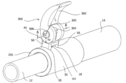
- the load bearing member further includes a pressing lever having an annular peripheral surface that rotates about an axis parallel to the load bearing surface while contacting the load bearing surface, the
- the pair of through slits may be provided in a tubular base portion that is attached and fixed to the outer circumferential surface of one end portion of the outer tube, and the inner tube may be fitted into the outer tube via the tubular base portion.
- a pin extending upright from an outer circumferential surface of the outer tube or the tubular base portion; a pivot fixed to the pin and extending parallel to the outer circumferential surface;
- the pressing lever has a rotating part that is pivotally supported on the pivot shaft and a grip part that extends from an outer edge of the rotating part,
- the pivot portion may preferably have an annular peripheral surface which abuts against the load bearing surface.
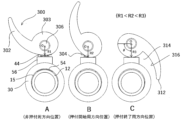
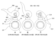
- the rotating part is pivotally supported on the pivot so that when the pressing lever rotates to a position corresponding to the intermediate radius, the direction connecting the tip of the grip part and the pivot shaft is in a substantially upright position, and when the pressing lever rotates to a position corresponding to the second radius, the direction connecting the tip of the grip part and the pivot shaft is in a pressed-down position.
- the rotating portion may have an annular peripheral surface that has the second radius over a predetermined central angle range with respect to the pivot axis in accordance with a desired pressing force applied to the outer peripheral surface of the inner tube by the pair of pressing bodies.
- the pin is screwed and fixed to the outer peripheral surface of the outer tube or the tubular base portion, and the height of the pivot shaft is adjustable by adjusting the amount of screwing.
- the rotating part has a notch in a direction intersecting the pivot axis and is provided with a pair of rotating parts facing each other through the notch, the pin is arranged within the notch and has a first through hole through which the pivot axis can pass, and each rotating part has a second through hole through which the pivot axis can pass rotatably, and the first through hole and the second through hole can be aligned and positioned so that the pivot axis can pass through.
- the annular peripheral surface may be elliptical, with the major axis of the ellipse constituting the second radius.
- the stand may be a music stand in which a music stand is fixedly supported by either the inner or outer tube, and a fixing support jig for the inner or outer tube as described in any one of claims 1, 5, 6, 15, 16, or 20 is provided at the fitting portion between the inner or outer tube or between the inner tube and a tubular base portion which is attached and fixed to the outer peripheral surface of one end of the outer tube.
- the table body may be fixedly supported to either the inner or outer tube, and the inner or outer tube or the inner tube and a tubular base portion attached and fixed to the outer peripheral surface of one end of the outer tube form the legs of the table body, and the fitting portion of the inner and outer tubes may have a fixing support jig for the inner and outer tubes described in any one of claims 1, 5, 6, 15, 16, and 20.
- the vehicle may have a saddle and/or handlebars fixedly supported to either the inner or outer tube, and a fixing support jig for the inner or outer tube as described in any one of claims 1, 5, 6, 15, 16, and 20 at a fitting portion between the inner or outer tube or between the inner tube and a tubular base portion attached and fixed to the outer peripheral surface of one end of the outer tube.
- the frame may have a fixing support jig for the inner and outer tubes described in any one of claims 1, 5, 6, 15, 16, and 20 at the fitting portion between the inner and outer tubes or between the inner tube and a tubular base portion attached and fixed to the outer peripheral surface of one end of the outer tube.
- the U-shaped portion may be fixedly supported at the tip of either the inner or outer tube, and the fitting portion between the inner or outer tube or the inner tube and a tubular base portion which is attached and fixed to the outer peripheral surface of one end of the outer tube may have a fixing support jig for the inner and outer tubes as described in any one of claims 1, 5, 6, 15, 16, and 20.
- the cart may have casters on one of the inner and outer tubes that fit together and a loading platform on the other, and may have a fixing support jig for the inner and outer tubes described in any one of claims 1, 5, 6, 15, 16, and 20 at the fitting portion between the inner and outer tubes or between the inner tube and a tubular base portion that is attached and fixed to the outer peripheral surface of one end of the outer tube.
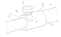
- each of the inner tube 12 and the outer tube 14 can be selected according to the application, and as will be described later, the fitting length between the inner tube 12 and the outer tube 14 is adjusted so that the overall length of the inner tube 12 and the outer tube 14 can be adjusted.
- each of the inner tube 12 and the outer tube 14 is hollow cylindrical, and the outer tube 14 is fitted onto the inner tube 12 by inserting the inner surface 17 of the outer tube 14 from one end opening into one end opening of the outer surface 15 of the inner tube 12.
- a slight clearance may be provided between the inner peripheral surface 17 of the outer tube 14 and the outer peripheral surface 15 of the inner tube 12, as long as the outer tube 14 is fixedly held in the longitudinal direction relative to the inner tube 12 by the fastening screw portion 24 via the pressing body 22, as will be described later.
- the slight clearance is, for example, 0.05 mm to 0.1 mm.
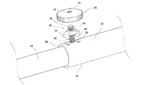
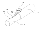
- a pair of through slits 18 are provided on the outer peripheral surface 16 of the outer tube 14, spaced apart by a distance D, and a female thread portion 20 is provided between the pair of through slits 18.
- the distance D between the pair of through slits 18 may be selected according to the application of the length adjustment jig 10, as will be described later.
- the pair of through slits 18 are provided so as to extend in the longitudinal direction of the inner and outer tubes 12, 14 at a predetermined interval from each other in the longitudinal direction of the inner and outer tubes 12, 14, respectively. More specifically, each of the pair of through slits 18 is an elongated opening, and the width of the opening need only be such that the pressing portion 22 can penetrate in the thickness direction. As will be described later, since the pressing body is fastened and fixed to the outer tube 14 via the fastening screw portion 24, there is no need for the pressing portion 22 to penetrate in a tight fit manner into the pair of through slits 18 provided on the outer peripheral surface 16 of the outer tube 14.
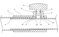
- the pressing portion 22 is positioned on the outer circumferential surface 16 of the outer tube 14 and passes through a pair of through slits 18 so as to come into contact with the outer circumferential surface 15 of the inner tube 12 . More specifically, the male thread portion 26 of the tightening screw portion 24 forms a pressing body 34 having an approximately U-shaped longitudinal cross section, which is provided with a clearance hole portion 32 penetrating in the thickness direction and two pressing portions 22 extending in opposite directions from the clearance hole portion 32.
- the pressing body 34 has a central portion 48 in which the clearance hole portion 32 is provided, and each of the pair of pressing portions 22 has an inclined portion 56 extending downward from the entire corresponding end portion of the central portion 48, and each of the pair of pressing portions 22 extends from the entire lower end of the inclined portion 56, and a pressing surface 54 is provided on the lower surface 38.
- Each of the pressing surfaces 54 which is the tip surface of the pressing portion 22, is shaped to follow the outer circumferential surface 15 of the inner tube 12 so as to be in surface contact with the outer circumferential surface 15 of the inner tube 12. For example, if the outer circumferential surface 15 of the inner tube 12 is the outer surface of a cylinder, the pressing surface 54 has a cross section in the shape of an arc of that diameter.
- the pressing body 34 itself does not need to be rotated toward the outer circumferential surface 15 of the inner tube 12, so that it is possible to press the pressing surface 54 against the outer circumferential surface 15 of the inner tube 12 in a direction in which the arc-shaped cross section matches the outer circumferential surface 15 of the inner tube 12.
- the pressing body 34 has a protrusion 42 on an upper surface 44, and the protrusion 42 is provided with a clearance hole 32.
- a contact surface 46 capable of contacting the outer circumferential surface 16 of the outer tube 14 is provided on the rear surface of the central portion 48 of the pressing body 34 . More specifically, a planar abutment surface 46 is provided around the lower end opening of the clearance hole portion 32, and the male threaded portion 26 is screwed into the female threaded portion 20 of the outer peripheral surface 16 of the outer tube 14 by the fastening screw portion 24 until the lower surface of the shank portion 36 abuts against the annular surface of the pressing body 34, so that the pressing surface 54 is clamped and fixed to the outer peripheral surface 15 of the inner tube 12 with the abutment surface 46 abutting against the outer peripheral surface 16 of the outer tube 14. As a result, the inner and outer tubes 12, 14 are fixed and held at a predetermined fitting length via the fastening screw portion 24 and the pressing body 34.
- the fastening screw portion 24 is configured to be able to press and fix the pressing portion 22 against the outer peripheral surface 15 of the inner tube 12, and the fastening screw portion 24 has a shank portion 36 and a male threaded portion 26 extending downward from a lower surface 38 of the shank portion 36, the male threaded portion 26 being able to screw into the female threaded portion 20, and an annular surface 40 surrounding the male threaded portion 26 is formed on the lower surface 38.
- the tightening screw portion 24 has a head portion 58 that can be gripped and rotated with fingers at the end of the shank portion 36 opposite the male threaded portion side end.
- the diameter of the head portion 58 is preferably as large as possible so that it can be gripped with little force with fingers and rotated, and from the viewpoint of preventing slippage, a plurality of shallow grooves spaced apart in the circumferential direction may be provided.
- the head portion 58 constitutes a torque applying grip 132 that applies rotation around the extension direction of the male threaded portion 26.
- the fixing and support effect is greater when the pair of pressing bodies 34 of the pressing section 22 are spaced apart in the extension direction of the inner and outer tubes 12, 14 rather than spaced apart in the circumferential direction of the inner and outer tubes 12, 14.
- the area of the pressing end face 54 of the pressing body 34 is constant, the frictional force between the pressing end face 54 and the outer peripheral surface of the inner tube 12, which is based on the clamping force of the clamping screw section 24, is important for fixing and support, so it is preferable for the clamping force per unit area to be greater. In this sense, too, it is advisable to provide multiple pressing end faces 54.
- a pair of through slits 18 are provided at a predetermined interval from each other in the longitudinal direction of the inner and outer tubes 12, 14, respectively, extending circumferentially of the inner and outer tubes 12, 14, the inner and outer tubes 12, 14 being oriented vertically, and either the inner or outer tube 12, 14 supporting a heavy object at a predetermined height.
- the length adjustment jig 10 when using the length adjustment jig 10 to adjust the fitting length of the inner and outer tubes 12, 14 extending in the vertical direction to fix and hold a heavy object at a predetermined height, from the standpoint of supporting the weight of the heavy object by the frictional force between the pressing surface of the pressing portion 22 and the outer peripheral surface 15 of the inner tube 12, the greater the resistance of the pressing surface of the pressing portion 22 against the outer peripheral surface 15 of the inner tube 12, i.e., the tightening force by the fastening screw portion 24, the better, and for this reason, strength sufficient to withstand such large tightening forces is required, so that the pressing portion 22 and fastening screw portion 24, as well as the inner and outer tubes 12, 14 that constitute the length adjustment jig 10, are preferably made of metal.
- the length adjustment jig 10 may be used in a stand that supports everyday items at a predetermined height, or in a vehicle that supports a saddle at a predetermined height.
- the overall length of the clothesline pole consisting of the inner and outer tubes 12, 14 can be adjusted according to the number of laundry to be hung by adjusting the fitting length of the inner and outer tubes 12, 14 using the length adjustment jig 10.
- each of the pair of pressing bodies 34 of the U-shaped cross-section pressing portion 22 is passed through the corresponding through slits 18 of the outer tube 14, and the male threaded portion 26 of the fastening screw 24 is passed through the clearance hole 32 of the pressing portion 22 and screwed into the female threaded portion 20 provided on the surface of the outer tube 14.
- each of the pair of pressing surfaces 54 spaced apart in the longitudinal direction of the inner and outer tubes 12, 14 of the pressing portion 22 is shaped to conform to the outer peripheral surface 19 of the inner tube 12, they abut against the outer peripheral surface 19 of the inner tube 12 to fix and support the inner and outer tubes 12, 14, and the male threaded portion 26 of the fastening screw 24 is inserted into the elongated groove 130.
- the overall length of the inner and outer tubes 12, 14 is adjusted by adjusting the fitting positions of the inner and outer tubes 12, 14, and then the inner and outer tubes 12, 14 are fixed and supported by the pressing portion 22, and the male threaded portion 26 of the fastening screw 24 is inserted and held in the elongated groove 130. Therefore, when a load that would cause relative rotation around the longitudinal direction of the tubes is applied between the inner and outer tubes 12, 14, it is possible to prevent the occurrence of such relative rotation. From this viewpoint, the depth of the elongated groove 130 may be determined by cutting the outer circumferential surface 16 of the outer tube 14 .
- the fastening screw portion 24 is similar to the first embodiment in that it has a male thread portion 26 which can be screwed into the female thread portion 20.
- the outer peripheral surface 16 of the outer tube 14 has a pair of through slits 18 and the female thread portion 20 between them
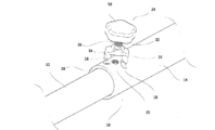
- a tubular protrusion 65 is provided at a position corresponding to the female thread portion 20, facing outwardly and perpendicular to the outer peripheral surface 16 of the outer tube 14. More specifically, the tubular protrusion 65 has a circular annular cross section with a predetermined height h, has a female thread 20 formed therein so as to align with the female thread 20, and is capable of being screwed with the male thread 26 of the fastening screw portion 24.
- the tubular protrusion 65 may be fixed to the outer circumferential surface 16 separately from the outer tube 14, for example, by welding.
- the outer shape of the tubular protrusion 65 does not need to be cylindrical, and may be any shape as long as the female thread 20 is formed therein so as to align with the female thread 20. According to this embodiment, it is effective when the thickness of the outer tube 14 is thin and the screw-in length of the male thread portion 26 cannot be sufficiently secured, and the predetermined height h may be determined from this viewpoint.
- the length of the male thread portion 26 is set so that the tip of the male thread portion 26 does not hit the outer circumferential surface 15 of the inner tube 12 when the pressing portion 22 is pressed and fixed against the outer circumferential surface 15 of the inner tube 12.
- the outer circumferential surface 16 of the outer pipe 14 may be ground inwardly around the female thread portion 20 between a pair of through slits 18 to form a shallow groove portion (not shown) having a bottom surface, and a through hole having the female thread portion 20 on the bottom surface may be provided.
- the depth of the shallow groove portion, i.e., the grinding depth of the outer circumferential surface 16 may be appropriately set according to the thickness of the outer pipe 14 and/or the length of the male thread portion 26, thereby ensuring versatility regardless of the conditions of the inner and outer pipes 12, 14 and the fastening screw portion 24.
- the fourth embodiment of the present invention is characterized by the fastening screw portion 24, and is a length adjustment jig 10 interposed between the inner tube 12 and outer tube 14 which are fitted together, and has a pressing portion 22 which passes through a pair of through slits 18 and comes into contact with the outer peripheral surface 15 of the inner tube 12, and a fastening screw portion 24 which is capable of pressing and fixing the pressing portion 22 against the outer peripheral surface 15 of the inner tube 12, which is common to the first embodiment.
- the fastening screw portion 24 has a male thread portion 26, and a pair of through slits 18 are provided on the outer peripheral surface 16 of the outer tube 14, and a female thread portion 20 is provided between the pair of through slits 18, in this embodiment, on the contrary, the fastening screw portion 24 has a nut portion 70 having a female thread portion 72, and a male thread portion 74 is provided on the outer peripheral surface 16 of the outer tube 14. More specifically, the nut portion 70 has a female thread portion 72 that can be screwed onto the male thread portion 74 penetrating through its center, and a shallow groove is provided on the outer peripheral surface to prevent slipping when tightening by hand.
- the male thread portion 74 is provided orthogonally facing outward relative to the outer peripheral surface 16 of the outer tube 14, and the female thread portion 20 is omitted.
- the male thread portion 74 may be fixed to the outer peripheral surface 16, for example, by welding. According to this embodiment, when the nut portion 70 is loosened, the pressing body 34 itself is maintained in a state inserted into the male thread portion 74 via the clearance hole 32. Therefore, it is possible to prevent the pressing body 34 itself from accidentally coming loose and falling apart when the fastening screw portion 24 is loosened, as in the first embodiment.
- the fifth embodiment of the present invention will be described below. In the following description, the same components as those in the first embodiment are given the same reference numerals and the description thereof will be omitted. Below, the characteristic parts of this embodiment will be described in detail with reference to FIG.
- the fifth embodiment of the present invention is characterized by a coil spring 76 provided between the outer peripheral surface 16 of the outer tube 14 and the pressing portion 22.
- the length adjustment jig 10 is interposed between the inner tube 12 and the outer tube 14 which are fitted together, and has a pressing portion 22 which passes through a pair of through slits 18 and contacts the outer peripheral surface 15 of the inner tube 12, and a fastening screw portion 24 which can press and fix the pressing portion 22 against the outer peripheral surface 15 of the inner tube 12.
- the fastening screw portion 24 is common to the first embodiment in that it has a male screw portion 26 which can be screwed into the female screw portion 20.
- a coil spring 76 is not provided. More specifically, a coil spring 76 is provided which can be inserted into the male threaded portion 26 of the tightening screw portion 24 through the clearance hole 32 of the pressing portion 22 and has a diameter larger than the diameter of the female threaded portion 20, and the number of turns of the coil may be set appropriately according to the U-shaped height of the pressing portion 22.
- the pressing portion 22 when the male threaded portion 26 of the tightening screw portion 24 is screwed into the female threaded portion 20, the pressing portion 22 is supported on the upper surface of the coil spring 76, so that the pressing end face 54 protrudes from the corresponding through slit 18 toward the outer peripheral surface 15 of the inner tube 12, making it possible to prevent the pressing portion 22 from getting in the way when moving the inner tube 12 relative to the outer tube 14 in the extension direction of the tubes in order to adjust the fitting position between the inner tube 12 and the outer tube 14.
- the pressing portion 22 is pressed upward toward the fastening screw portion 24, strengthening the screwed state between the male threaded portion 26 and the female threaded portion 20. It is also possible to prevent in advance, for example, the fastening screw portion 24 from loosening over time, causing the fixed support between the inner tube 12 and outer tube 14 which are fitted together to become unstable.
- the sixth embodiment of the present invention is characterized by a protective plate 78 provided between the inner tube 12 and the outer tube 14.
- the sixth embodiment of the present invention is a length adjustment jig 10 interposed between the inner tube 12 and the outer tube 14 which are fitted together, and has a pressing portion 22 which passes through a pair of through slits 18 and contacts the outer peripheral surface 15 of the inner tube 12, and a fastening screw portion 24 which can press and fix the pressing portion 22 against the outer peripheral surface 15 of the inner tube 12.
- the fastening screw portion 24 is common to the first embodiment in that it has a male thread portion 26 which can be screwed into the female thread portion 20.
- a protective plate 78 is not provided. More specifically, the protective plate 78 has a width W that is longer than the length of the pair of through slits 18, and a length L that is longer than the distance between the pair of through slits 18 in the extension direction of the inner and outer tubes 14, and is made of a material that is softer than the outer peripheral surface 15 of the inner tube 12.
- a shallow groove 80 of a size that allows the protective plate 78 to fit into is provided on the inner peripheral surface of the outer tube 14 in which the pair of through slits 18 are provided.
- the protective plate 78 When the protective plate 78 is fitted into the shallow groove 80, it protrudes slightly inward from the inner peripheral surface of the outer tube 14. When the fastening screw portion 24 is tightened, the pressing portion 22 is pressed and fixed against the outer peripheral surface 15 of the inner tube 12, so that the protective plate 78 is also crushed, and the pressing end face 54 comes into direct contact with the outer peripheral surface 15 of the inner tube 12, making it possible to prevent the outer peripheral surface 15 of the inner tube 12 from being scratched or dented. Furthermore, by making the protective plate 78 out of rubber, which has a high friction coefficient, it is possible to ensure the frictional force between the protective plate 78 and the outer peripheral surface 15 of the inner tube 12, thereby further strengthening the fixed support between the inner tube 12 and the outer tube 14.
- FIG 17 shows a modified example in which a pair of protective plates 82 are provided, and each protective plate 82 is arranged so that it can be fitted into the corresponding through slit 18.
- each protective plate 82 is also crushed, preventing the outer peripheral surface 15 of the inner tube 12 from being scratched or dented, and ensuring friction between the protective plates 82 and the outer peripheral surface 15 of the inner tube 12.
- the shallow groove 80 provided on the inner surface of the outer tube 14 can be omitted.
- the seventh embodiment of the present invention will be described below. In the following description, components similar to those in the first embodiment are given the same reference numerals and description thereof will be omitted. Below, the characteristic parts of this embodiment will be described in detail with reference to FIG.
- the seventh embodiment of the present invention is characterized in that the seventh embodiment is a length adjustment jig 10 interposed between an inner tube 12 and an outer tube 14 that are fitted to each other, and has a pressing portion 22 that passes through the pair of through slits 18 and contacts the outer circumferential surface 15 of the inner tube 12, and a fastening screw portion 24 that can press and fix the pressing portion 22 against the outer circumferential surface 15 of the inner tube 12, and the fastening screw portion 24 has a male screw portion 26 that can be screwed into the female screw portion 20, which is common to the first embodiment.
- the orientation of the pair of through slits 18 and the female threaded portion 20 between the pair of through slits 18 provided on the outer peripheral surface 16 of the outer tube 14 was along the extension direction of the inner tube 12 and the outer tube 14, whereas in this embodiment, the orientation of the pair of through slits 18 and the female threaded portion 20 between the pair of through slits 18 is oblique to the extension direction of the inner tube 12 and the outer tube 14, and accordingly, the orientation of the pressing body 34 provided via the pair of through slits 18 is oblique.
- the oblique angle of the pair of through slits 18 and the female thread portion 20 between the pair of through slits 18 with respect to the extension direction of the inner tube 12 and the outer tube 14 should be determined from this viewpoint.
- the eighth embodiment of the present invention will be described below. In the following description, components similar to those in the first embodiment are given the same reference numerals and description thereof will be omitted. Below, the characteristic parts of this embodiment will be described in detail with reference to FIG.
- the eighth embodiment of the present invention is characterized in that a pressing body 34 is provided on the outer tube 14.
- the length adjustment jig 10 is interposed between the inner tube 12 and outer tube 14 which are fitted together, and has a pressing portion 22 which passes through a through slit 18 and comes into contact with the outer peripheral surface 15 of the inner tube 12, and a fastening screw portion 24 which is capable of pressing and fixing the pressing portion 22 against the outer peripheral surface 15 of the inner tube 12.
- the fastening screw portion 24 has a male thread portion 26 which can be screwed into the female thread portion 20, which is common to the first embodiment.
- a pair of through slits 18 were provided in the outer peripheral surface 16 of the outer tube 14, and accordingly the pressing body 34 had a clearance hole portion 32 in the center and a pair of pressing surfaces 54, but in this embodiment, a single through slit 18 is provided, and accordingly a single pressing body 34 is provided.
- the length adjustment jig 10 has a ceiling side fixing portion 90 provided on the upper end surface 98 of the inner tube 12 of the length adjustment jig 10, and a shelf side fixing portion 84 provided on the lower end surface 96 of the outer tube 14 of the length adjustment jig 10, and the length adjustment jig 10 is interposed between the ceiling side fixing portion 90 and the shelf side fixing portion 84.
- the ceiling-side fixing portion 90 has an abutment surface 92 that can abut against the ceiling surface, and has a receiving portion 94 that can receive an upper end surface 98 .
- the shelf-side fixing part 84 has abutment surfaces 89 that are perpendicular to each other so that it can be attached to the clearance between the wall and the shelf at the corner of the walls that intersect perpendicularly, and abutment surfaces 86 that can abut against the top surface of the shelf, and also has a receiving part 88 that can receive a lower end surface 96.
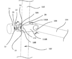
- the upper end 106 of the first support bar 104 rotates around the pivot 108 relative to the tubular portion 102 while adjusting the fitting position of the tubular base portion relative to the second support bar 112.
- the tightening screw portion 24 screws the male threaded portion 26 into the female threaded portion 20 via the clearance hole 32, while the pressing portion 22 passes through the through hole 18, and the tip surface is pressed and fixed in a surface contact manner against the outer peripheral surface 16 of the second support bar 112, making it possible to adjust the inclination angle of the second support bar 112 relative to the contact surface.
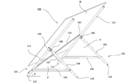
- Each of the tubular portions 102 further has a pair of opposing overhanging flanges 116 that extend from its outer surface in a direction intersecting the extension direction of the tubular portion 102, and each of the pair of overhanging flanges 116 has a first through hole 120 that can receive a corresponding end 118 of the pivot shaft 108, and the upper end 106 of the first support bar 104 is provided with a second through hole 122 through which the pivot shaft 108 can pass in a direction intersecting the extension direction of the first support bar 104, and the upper end 106 of the first support bar 104 is positioned between the pair of overhanging flanges 116 so that the first through hole 120 and the second through hole 122 are aligned, and the pivot shaft 108 is provided passing through each of the first through holes 120 and the second through hole 122.
- a pair of such inclination angle adjustment jigs are provided so that the planes P formed by both support bars are parallel, and the rectangular plate-shaped weight W is supported at four points by the lower ends 103 of the first support bars 104 and the lower ends 103 of the second support bars 112 of the inclination angle adjustment tool while each of the opposing edges of the rectangular plate-shaped weight W is supported by each of the second support bars 112 of the inclination angle adjustment tool, and the inclination angle ⁇ of the rectangular surface of the rectangular plate-shaped weight W is adjusted by adjusting the fitting position of each of the tubular base parts of the inclination angle adjustment tool relative to the corresponding second support bars 112 of the inclination angle adjustment tool, thereby forming a support and inclination angle adjustment device for the rectangular plate-shaped weight W.
- the pair of inclination angle adjustment jigs are connected by an X-shaped cross member 124.
- the second support bar 112 is fitted inside the tubular portion 102 so as to be movable in the longitudinal direction of the tube, and the first support bar 104 is connected to the tubular portion 102 via a pivot 108 and is rotatable about the pivot 108.
- the outer circumferential surface of the tubular portion 102 is provided with a female screw portion and at least one through hole within a predetermined range from the female screw portion 72, and has at least one pressing portion 22 that passes through the through hole from the outer circumferential surface of the tubular base portion 102 and abuts on the outer circumferential surface of the second support bar 112, and a fastening screw portion 24 that can press and fix the pressing portion 22 against the outer circumferential surface of the second support bar 112, and the tip surface of the pressing portion 22 is shaped to follow the outer circumferential surface of the second support bar 112 so as to be in surface contact with the outer circumferential surface of the second support bar 112.
- the inclination angle ⁇ of second support bar 112 with respect to the contact surface can be adjusted with simple operation without requiring excessive tightening force with a simple structure; for example, when a rectangular heavy object is supported by second support bar 112, the inclination angle ⁇ of the rectangular surface can be adjusted.
- a single pivot 108 passing through the horizontal direction of the solar panel is used as a shared pivot 108.
- a torque-applying grip provided on only one side is used to manually loosen and retighten the fastening, and the weight of the solar panel acts to automatically rotate the single pivot 108 during this time, making it possible to continuously adjust the tilt angle ⁇ of the solar panel depending on the time width of the fastening and loosening.
- the feature of the eleventh embodiment of the present invention is that, whereas in the above-mentioned embodiments, the inner and outer tubes 14 were used only to adjust the length of the inner and outer tubes 14 by adjusting the fitting positions of the inner and outer tubes 14, or the inner and outer tubes 14 were used only as a stand while supporting a weight object with either the inner or outer tube 14 and adjusting only the inclination angle ⁇ of the rectangular surface of the rectangular weight object with either the inner or outer tube 14, the present embodiment is adapted to be applied to traffic signs, so that the inclination angle ⁇ , lateral position, and height of the traffic sign can all be adjusted.
- the present invention has inner and outer tubes 12, 14 that stand vertically from the ground, a tubular section 102 that is provided crossing the upper end of the outer tube 14, a diagonal tube 126 that fits inside the tubular section 102, and a traffic sign T that is provided at the upper end of the diagonal tube 126, and the height of the inner and outer tubes 12, 14 can be adjusted, and by adjusting the position of the diagonal tube 126 relative to the tubular section 102, the lateral position can be adjusted, and the inclination angle ⁇ of the traffic sign T relative to the upper end of the diagonal tube 126 can be adjusted.
- the present invention is applied to a fixed support jig for a stand that supports and fixes a heavy object with either the inner or outer tubes 12, 14, an overall length adjustment jig for the inner and outer tubes 12, 14, and an inclination angle adjustment jig that rotatably connects the inner tube 12 and the outer tube 14 via a pivot 108 and adjusts the fitting position of the inner tube 12 and the outer tube 14.
- each adjustment jig is the same as that of the above-described embodiment, and therefore a detailed description thereof will be omitted. According to the above configuration, it is possible to stably support traffic signs T that are permanently placed outdoors and may extend over several tens of kilometers, while easily adjusting the orientation and/or position thereof.
- the inner and outer tubes 14 could be used only to adjust the length of the inner and outer tubes 14 by adjusting the fitting positions of the inner and outer tubes 14, or the inner and outer tubes 14 could be used only as a stand while supporting a weight object with either the inner or outer tube 14 and adjusting only the inclination angle ⁇ of the rectangular surface of the rectangular weight object with either the inner or outer tube 14 supported, the present embodiment is adapted to be applied to traffic signs, so that the inclination angle ⁇ , lateral position, and height of the traffic sign can all be adjusted.
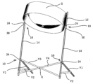
- a pair of inner and outer tubes 12, 14, which fit together using a length adjustment jig, are provided so as to extend parallel to each other at a specified distance and diagonally upwards, and the lower parts of the outer tubes 14 of the pair of inner and outer tubes 12, 14 are connected by members Y3 and Y5, and a steel pan (musical instrument) to be supported at a specified height is placed between the upper parts of the inner tubes 12 of the pair of inner and outer tubes 12, 14, and members Y1 and Y2 are connected to the lower parts of each of the outer tubes 14 of the pair of inner and outer tubes 12, 14 so as to jam and support each of the pair of inner and outer tubes 12, 14 which are suspended diagonally from the upper ends of the inner tubes 12 and extend diagonally upwards, thereby supporting the steel pan (musical instrument) at four points.
- the length adjustment jig is used to adjust the fitting lengths of the pair of inner and outer tubes 12, 14 so that they are the same, thereby allowing the steelpan (musical instrument) to be supported and fixed horizontally at the desired height.
- the fixing support jig of the present invention is also applied to the connection between the X-shaped crossing members Y3, Y4 and the outer tube 14, and the fixing support jig of the present invention is used for the fitting portion of the inner and outer tubes 12, 14 to support the steel pan at a specified height, and when folding the stand after use, the fastening screw portion 24 of the fixing support jig is loosened and the fixing support jig is moved upward along the outer tube 14 to straighten the X-shaped crossing members Y3, Y4.
- the fixing support jig is the same as that of the eleventh embodiment, so a detailed description thereof will be omitted.
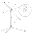
- the entire outer tube fits onto the outer peripheral surface of a diagonal bar which fixes the microphone to one end and adjusts its height, and by using a length adjustment jig 10 for this fitting position, it is possible to easily adjust not only the height but also the lateral position of the microphone.
- the first to ninth embodiments are described as a length adjustment jig
- the tenth to twelfth embodiments are described as a fixed support adjustment jig serving as a stand for supporting a weight
- the twelfth embodiment is described as an inclination angle adjustment jig.
- all of these jigs are common to the integral structure of the inner and outer tubes 12, 14 that constitutes these jigs at the fitting position of the inner and outer tubes 12, 14.
- the manufacturing method of the integral structure of the inner and outer tubes 12, 14 is as follows: A step of machining, 3D printer modeling, or lost wax processing a pair of through slits 18 and a female screw portion 72 on an outer surface of a solid or hollow inner tube 12 and a hollow outer tube 14 that fit together, the outer surface corresponding to the fitting portion of the outer tube 14; This is a step of preparing a pressing portion 22 having a U-shaped cross section, which penetrates a pair of through slits 18 from the outside of the outer surface and can be pressed against the outer circumferential surface 15 of the inner tube 12 in a tight contact manner by surface contact at two points, the pressing portion 22 having a clearance hole 32, and a tightening screw portion 24 having a female screw portion 72 and a torque application grip 132 that can be screwed into the female screw portion 72, in which the diameter of the torque application grip 132 is selected according to the support load so that it can be firmly supported by hand force alone, and at a predetermined fitting position, the male screw
- the pressing portion 22 is thin relative to the width of the load receiving surface, it may be called a pressing plate, and when the pressing portion 22 is thick relative to the width of the load receiving surface, it may be called a pressing block.
- the inner tube 12 and the outer tube 14 may be made of either metal or resin, and may be manufactured based on either a solid material or a molten material.
- the manufacturing methods are broadly classified as follows: If the material is metal, solid materials can be machined, such as by pressing, cutting, or drilling, while molten materials can be cast or modeled using a 3D printer. If the material is resin, solid materials can be machined, while molten materials can be molded, such as by injection molding or blow molding, or modeled using a 3D printer. In particular, when metal casting is used, the lost wax method or full mold method is preferred, and when metal modeling is performed using a 3D printer, metal powder is used.
- the inner tube 12 and the outer tube 14 are preferably made of resin from the viewpoint of light weight, but the male threaded portion 26 of the fastening screw and the female threaded portion 72 into which the male threaded portion 26 screws are both preferably made of metal from the viewpoint of durability.
- a metal nut having the male threaded portion 26 may be fitted into the opening of the resin outer tube 14, or when the thickness of the resin outer tube 14 is thin, a thickness may be increased locally in order to ensure the thickness of the female threaded portion 72.
- the 3D printed object is produced by a known method called fused deposition modeling using a 3D printer.
- the production method includes a step of melting a resin composition or a filament, and a step of extruding the resulting melt from a nozzle of a 3D printed object production device to produce a 3D printed object.
- the melting step the propylene resin composition for 3D printers or the 3D print filament is melted.
- the heating means for melting the 3D print material is not particularly limited, and any known heating means can be used.
- the temperature at which the 3D printing material is melted is not particularly limited and may be set appropriately depending on the properties of the thermoplastic resin.
- the temperature at which the 3D printing material is melted may be, for example, a temperature of +10 to +150° C. based on the higher of the melting point or glass transition temperature (Tg) of the thermoplastic resin.
- Tg glass transition temperature
- the 3D printing material may be melted and kneaded. By melting and kneading the 3D printing material, the 3D printing material tends to be mixed more uniformly. Therefore, the occurrence of unevenness in the material of the obtained 3D printed object is easily suppressed. As a result, the deformation of the 3D printed object tends to be further suppressed.
- the 3D printing material melted in the melting process is extruded from a nozzle to form a 3D printed object.
- the molten 3D printing material is extruded from a nozzle of a 3D printed object manufacturing device, and a 3D printed object can be formed by sequentially stacking 2D layers on a substrate based on multiple 2D data.
- the multiple 2D data are generated by slicing the 3D coordinate data of the 3D printed object to be formed into slices using slicer software.
- the 3D print object manufacturing device may be a material extrusion type 3D print object manufacturing device.
- the material extrusion type 3D print object manufacturing device is not particularly limited, and a known device or known device configuration may be applied.
- the 3D print object manufacturing device may be, for example, a device including a cylinder, a nozzle, and a heating means.
- the 3D print object manufacturing device is supplied with a material for 3D print modeling.
- the nozzle is provided at a downstream side of the cylinder in the discharge direction of the material for 3D print modeling.
- the nozzle discharges the material for 3D print modeling.
- the heating means is provided at the cylinder.
- the heating means heats and melts the material for 3D print modeling.
- the 3D print object manufacturing device extrudes the heated and melted 3D print material from a nozzle, and layer-by-layer models the 3D print material extruded from the nozzle. This produces a 3D print object.
- the 3D print material may be solidified by applying ultraviolet light to it using a conventionally known photolithography method.
- the cylinder may have a screw therein, the screw kneading the 3D printing material.
- the 3D printing object manufacturing apparatus may further include a table device that is disposed opposite the nozzle.
- the molten 3D printing material extruded from the nozzle is stacked on the table device.
- the 3D printing object manufacturing apparatus may further include a control means for controlling the spatial coordinates of the substrate and the nozzle, and the amount of the 3D printing material extruded from the nozzle.
- the control means preferably controls the discharge of the molten 3D printing material extruded from the nozzle, and controls the movement of the nozzle and/or the table device in the X-axis, Y-axis, and Z-axis directions relative to a reference plane.
- a photolithography method may be used in which a molten 3D printing material is solidified by ultraviolet light.
- the lost wax process can be broadly divided into two types of casting based on the manufacturing method: the pattern used to create the mold is removed from the mold by dissolving or burning it off, and the space between the pattern and the remaining gap is filled with molten metal to cast the product (burnt pattern methods such as the lost wax process and full mold process), and the pattern itself is not burned off, but is demolded (physically removed) from the mold to create the mold shape, or the mold itself is machined, etc., and the casting is then cast (non-burnt pattern methods such as the Shaw process and die casting process).
- burnt pattern methods such as the lost wax process and full mold process
- the lost wax process uses wax as the model material, and a model formed using a metal mold is layered with a slurry mold material, hardened, and then dewaxed (heated and dissolved, burned off), and the space where the original model was is filled with molten metal to create a casting.
- the full mold process uses a resin material such as polystyrene foam as the model material, and a model made using a metal mold or directly machined is embedded in the mold material, and molten metal is poured in as it is, and the model disappears as the molten metal is filled in to create a casting.
- the pressing surface has an outer shape of a long and thin rectangle, and the area of the long and thin rectangle is determined from the viewpoint of the increase or decrease in pressing pressure due to the fastening force of the screw.
- the inner and outer tubes 12, 14, and especially the inner tube 12 are made of resin, it is preferable to ensure the area of the long and thin rectangle from the viewpoint of protecting the outer circumferential surface 15 of the inner tube 12.
- the surface shape is preferably a shape that follows the outer circumferential surface 15 of the inner tube 12 so that it can abut closely against the outer circumferential surface 15 of the inner tube 12.
- the inner tube 12 when the inner tube 12 has a circular cross section, it should be an arc-shaped curved surface; when the inner tube 12 has a rectangular cross section, it should be a flat surface when abutting against one surface of the rectangular cross section; and when abutting against a corner of the rectangular cross section, it should be bent inward in a broken line so as to straddle two adjacent intersecting surfaces, and each should be a flat surface.
- the diameter of the torque application grip 132 is selected according to the support load determined according to the application of the integral structure of the inner and outer tubes as a length adjustment jig, an inclination angle adjustment jig, or a fixed support jig for a stand, and at a predetermined fitting position of the inner and outer tubes, the tightening screw portion is tightened by hand force via the torque application grip 132 to screw the male screw portion into the female screw portion through the clearance hole portion 32, thereby rotating the pressing portion 22 toward the outer peripheral surface 15 of the inner tube 12.
- a total length adjustment jig for the inner and outer tubes, or a tilt angle adjustment jig that rotatably connects the inner tube 12 and the outer tube via a pivot and adjusts the fitting position of the inner tube 12 and the outer tube, or a fixed support jig for a stand that supports and fixes a heavy object with either the inner or outer tube, is constructed, and the inner tube 12 and the outer tube are fixed together in the longitudinal direction of the tube to complete it, and it is possible to provide a manufacturing method for an integrated structure of inner and outer tubes that can firmly support the inner and outer tubes together by hand force alone, depending on various applications.
- the pressing body 34 is pressed into the through slit 18 while being deformed. Even if the fastening screw 24 is loosened too much and the pressing portion 22 completely comes out of the corresponding through slit 18, the pressing portion 22 is engaged and held in the pair of through slits 18, thereby effectively preventing it from falling off.
- the pressing body 34 has a V-shaped cross section along the upper surface 44 to the pressing surface 54, while the cross section of the pair of through slits 18 in the thickness direction of the inner and outer tubes 12 and 14 is V-shaped, and each of the through slits 18 has an inclined inner side surface 150 and an inclined outer side surface 152 facing each other as a through hole into which the pressing body 34 can be inserted in the thickness direction of the outer tube 14, and the first angle ⁇ 2 of the inclined outer side surface 35 of each of the pair of pressing bodies 34 with respect to the upper surface 44 is larger than the second angle ⁇ 1 of the inclined surface of the corresponding through slit 18 with respect to the outer peripheral surface 15 of the inner tube 12.
- the inclined inner side surface 150 and the inclined outer side surface 152 constituting the through slit 18 are set parallel to each other. For example, the difference between the difference between the
- each pressing surface 54 of the pressing body 34 is positioned at the opening 154 of the corresponding through slit 18.
- the width T2 of the opening 154 is set to be larger than the thickness T1 of the inclined portion 56
- the distance L2 between the upper edges of the inclined outer side surfaces 152 at the opening 154 is set to be a predetermined value smaller than the distance L1 between the outer edges of the pressing surfaces 54 of the inclined portion 56.
- the tightening screw portion 24 is tightened to move the pressing body 34 toward the outer circumferential surface 15 of the inner tube 12 via the upper surface 44, which is the load-receiving surface of the pressing body 34, and the pressing body 34 moves through the through slits 18 toward the inner tube 12 until the pressing surface 54 of each inclined portion 56 contacts the inclined inner surface 150 of the corresponding through slit 18.
- the tightening screw portion 24 is further tightened to forcibly deform each inclined portion 56 so that the first angle ⁇ 2 becomes smaller, and the inclined inner surface 150 of the corresponding through slit 18 is used as a guide surface to press in and move the pressing body 34 inside the through slit 18 toward the inner tube 12.
- the inner tube 12 is firmly fixed and supported against the outer tube 14 by support at three points: the two pressing end faces 54 and one line contact extending in the longitudinal direction of the tube.
- the length l from the upper surface 44 of the pressing portion 34 to the pressing surface 54 is set so that the pressing surface 54 of each inclined portion 56 can abut against the outer circumferential surface 15 of the inner tube 12 .
- the predetermined value which is the difference between the intervals L2 and L1
- the predetermined value can be determined from the standpoint of press-fitting while deforming each inclined portion 56 so that the first angle ⁇ 2 becomes small within the range in which the tightening screw portion 24 is tightened by hand, and while utilizing the inclined inner surface 150 of the corresponding through slit 18 as a guide surface.
- the bending rigidity of the pressing body 34 can be set according to the material of the pressing body 34, the thickness T1 of the inclined portion 56, and the length l from the upper surface 44 of the pressing portion 34 to the pressing surface 54. For example, when setting the length l from the upper surface 44 of the pressing portion 34 to the pressing surface 54 to be long, it is sufficient to ensure the thickness T1 of the inclined portion 56.
- the Young's modulus is large due to the material of the pressing body 34, it is sufficient to set the length l from the upper surface 44 of the pressing portion 34 to the pressing surface 54 to be long, or to set the thickness T1 of the inclined portion 56 to be small.
- the V-shaped configuration of the pressing body 34 and the through slit 18 as long as the pressing body 34 can be pressed into the through slit 18, it does not have to be a diagonal straight line configuration but may be a curved configuration, and in this case, the inclined outer surface 152 opposite the press-in surface may be a free-form surface shape as long as clearance can be secured while the pressing body 34 moves within the through slit 18.
- the pressing portion 22 when the pressing portion 22 is deformed into a figure eight by press-fitting, the pressing surface 54 must be processed taking into consideration the direction of the pressing surface 54 before deformation so that the pressing surface 54 abuts against the outer peripheral surface 15 of the inner tube 12.
- the first angle ⁇ 2 may be set to be larger than the first angle ⁇ 2, so that when the pressing body 34 is inserted into the through slit 18, it comes into contact with the inclined outer surface 152, and is pressed in so that the first angle ⁇ 2 becomes smaller, using the inclined outer surface 152 as a guide surface.
- an opening may be provided on the outer peripheral surface 16 of the outer tube 14 on the diametrically opposite side to the female threaded portion 20, and the male threaded portion 26 of the fastening screw 24 may be screwed into the female threaded portion 20 through the clearance hole 32 of the pressing plate.
- a processing tool may be inserted into the inside of the outer tube 14 from the opening to crimp the tip of the male threaded portion 26 to the extent that it does not impede the relative movement in the longitudinal direction of the fitting portion of the inner and outer tubes 12, 14, thereby forming a protrusion around the opening of the through slit 18 on the inner peripheral surface side of the outer tube 14, thereby preventing the fastening screw 24 from being loosened too much and the pressing portion 22 of the pressing portion from completely coming out of the corresponding through slit 18.
- the fourteenth embodiment of the present invention will be described below. In the following description, components similar to those in the first embodiment are given the same reference numerals and description thereof will be omitted. Below, the characteristic parts of this embodiment will be described in detail with reference to FIG.
- the feature of the 14th embodiment of the present invention is that in the 13th embodiment, by pressing the pressing portions 22 into the corresponding through slits 18, even if the fastening screws 24 are loosened too much and the pressing portions 22 of the pressing portions come completely out of the corresponding through slits 18, the pressing portions 22 are engaged and held in the pair of through slits 18, thereby making it possible to effectively prevent the pressing portions 22 from falling off, whereas in this embodiment, although the pressing portions 22 are prevented from falling off in common, an insertion rod is inserted into the pressing bodies 34 of the pressing portions 22.
- the tubular base portion 30 is fitted and fixed to the end portion of the outer tube 14, for example, by screw fixing. More specifically, as shown in FIG. 41 , of the pair of pressing bodies 34, in the pressing body 34 closer to the end of the outer tube 14 on the side of the fitting portion between the outer tube 14 and the inner tube 12, an insertion hole 204 is provided in the thickness direction of the pressing body 34 from the side closer to the end of the outer tube 14 of the pair of opposing side surfaces constituting the pressing body 34, and a slender hole 202 with a circular cross section is provided in the end face 201 on the fitting portion side of the outer tube 14, having a circular opening in the end face 201 and extending through to the side surface closer to the end of the outer tube 14, and further has an insertion rod 200 that can be inserted into the slender hole 202 from the circular opening.
- the slender hole 202 communicates with the insertion hole 204, and by inserting the tip portion 208 of the insertion rod 200 into the insertion hole 204, the pressing plate is held in the pair of through slits 18.
- the elongated hole 202 has a female threaded portion 206, and the insertion rod 200 is a set screw 200 of a fixed diameter that can be screwed into the female threaded portion 206 of the elongated hole 202. While the set screw 200 is screwed into the elongated hole 202, the tip portion 208 is inserted into the insertion hole 204, whereby the pressing plate is removably held within the pair of through slits 18.
- the female thread portion 206 does not have to be provided over the entire length of the elongated hole 202, but may be provided with a clearance hole partway from the circular opening of the elongated hole 202 into which the set screw 200 can be inserted, and may be provided from near the side surface close to the end of the outer tube 14 to the side surface, thereby making it possible to easily attach the set screw 200.
- an insertion rod 200 that can simply be inserted into the slot 202 may be used instead of the set screw 200 having a male thread. In this case, the diameter of the insertion rod 200 needs to be such that it can be tightly fitted into the slot 202.
- the fifteenth embodiment of the present invention will be described below. In the following description, components similar to those in the first embodiment are given the same reference numerals and description thereof will be omitted. Below, the characteristic parts of this embodiment will be described in detail with reference to Figs. 42 to 46.
- the feature of the fifteenth embodiment of the present invention is that while in the above-described embodiments the pressing body 34 against the outer peripheral surface 15 of the inner tube 12 was performed by rotating the fastening screw portion 24 in a screw-in type manner, in this embodiment a pressing lever mechanism 300 is adopted as an alternative to the fastening screw portion 24 to press the pressing body 34 against the outer peripheral surface 15 of the inner tube 12.
- the rotating portion 303 is provided with a notch 310, and is separated into rotating portions facing each other, a pin 304 is positioned within the notch 310, and the pivot 306 that penetrates the pin 304 penetrates a through hole with a circular cross section provided at each rotating portion, so that each rotating portion, i.e., the pressing lever 301, can rotate around the pivot 306 between a non-pressing circumferential position and a pressing circumferential position.
- the pressing lever 301 may be made of resin from the viewpoint of light weight.
- the length L of the arm from the center O of the pivot 306 of the grip lever portion 302 is preferably determined so that the pressing lever 301 can be sufficiently pressed down by hand force using the principle of leverage.
- Each rotating portion has a curved peripheral surface 308, and while the pressing lever 301 rotates around the pivot 306 between a non-pressing circumferential position and a pressing circumferential position, one of the portions of the curved peripheral surface 308 is held in contact with the upper surface 44 of the pressing body 34, so that the rotation of the pressing lever 301 causes the pressing body 34 to move in the thickness direction of the outer tube 14 within the through slit 18.
- the distance between the center O of the pivot 306 and the upper surface 44 of the pressing body 34 is R1
- the distance between the center O of the pivot 306 and the upper surface of the pressing body 34 is R2
- the distance between the center O of the pivot 306 and the upper surface of the pressing body 34 is R3, with R1 > R2 > R3 being set, so that the pressing body 34 is pressed against the outer peripheral surface 15 of the inner tube 12 due to the difference between R2 and R3.
- the difference between R2 and R3 may be set so that the pressing force of the pressing body 34 is sufficient to hold the inner and outer tubes 12, 14 in place.
- the curved peripheral surface 308 is set to smoothly change from R1 to R3, and it is preferable to form an arc portion having a central angle range of, for example, 90 degrees and a constant R3 from the curved peripheral surface portion corresponding to the circumferential pressing start position of the pressing lever 301 relative to the center O of the pivot shaft 306, so that the pressing lever 301 is fixedly held at the pressing circumferential position, and to set it so that the central angle range gradually becomes smaller from there.
- the entire curved peripheral surface 308 may be configured from a combination of multiple arc portions that are smoothly connected to each other, or may be an ellipse whose major axis corresponds to R3. It is preferable to determine the curved shape of the grip lever portion 302 so that when the pressing lever 301 is positioned at the circumferential position where pressing begins, the grip lever portion 302 is oriented approximately upright so that it can be easily pressed down by hand force, and when the pressing lever 301 is positioned at the circumferential position where pressing ends, the grip lever portion 302 is oriented close to the outer peripheral surface of the outer tube 14 so as not to protrude from the outer peripheral surface of the outer tube 14 and get in the way, and so that a space 314 is formed between the inner surface 316 of the grip lever portion 302 and the outer peripheral surface of the outer tube 14 for inserting a finger.
- the pin 304 stands upright with its lower end screwed into the outer circumferential surface 16 of the outer tube 14, and has a through hole (not shown) in the middle through which the pivot 306 can pass. By adjusting the amount of screwing at the lower end, the height of the pivot 306 from the outer circumferential surface 16 of the outer tube 14 can be adjusted.
- the height of the pivot 306 relative to the outer peripheral surface 16 of the outer tube 14 can be adjusted, and then the pressing lever 301 can be rotated about the pivot 306 from the non-pressing circumferential position to the pressing circumferential position, so that the pressing body 34 is pressed against the outer peripheral surface 15 of the inner tube 12 via the curved peripheral surface 308 of the rotating portion 303.
- the pressing lever 301 By pressing the pressing lever 301 down from the non-pressing circumferential position to the pressing circumferential position with a single touch, it is possible to fix and hold the inner and outer tubes 12, 14 while maintaining the pressing circumferential position of the pressing lever 301. Conversely, by pressing the pressing lever 301 up from the pressing circumferential position to the non-pressing circumferential position with a single touch, the inner and outer tubes 12, 14 can be moved relative to each other in the longitudinal direction of the tubes.
- the pin 304 and the pivot 306 may be integrally formed.
- the pivots 306 may be provided separately on the outer circumferential surface of the pin 304, extending in opposite directions from diametrically opposite positions, without providing a through hole for the pivot 306 in the pin 304.
- the lower end of the pin 304 may be fixed without being provided with a rotatable threaded portion.
- Figure 47 Modified examples of the pin 304 are shown in Figure 47.
- Figure 47(A) shows a case where the male threaded portion 310 and the main body portion 322 are integrated
- Figure 47(B) shows a case where the male threaded portion 310 and the main body portion 322 are separate.
- the height of the pivot 306 that fits into the through hole 318, i.e., the main body 322 can be adjusted relative to the outer tube 14 or the outer peripheral surface 16 of the tubular base part 30 that fits into the outer tube 14 by adjusting the amount of screwing of the male thread part 310 into the female thread part 326 of the outer tube 14 or the tubular base part 30 that fits into the outer tube 14.
- the pressing force of the pressing body against the outer peripheral surface 15 of the inner tube 12 by pressing down the pressing lever 300 and the distance between the tip 312 and the outer tube 14 or the outer peripheral surface 16 of the tubular base part 30 that fits into the outer tube 14 when pressing by the pressing lever 300 is completed can be adjusted, but they differ in the following points.
- Fig. 47(A) to adjust the amount of screwing, pin 304 is rotated, which changes the installation orientation of pressing lever 300 fixed to pin 304 via pivot 306, and is therefore suitable for a small amount of screwing adjustment.
- Fig. 47(B) male threaded portion 310 is inserted into hollow portion 320 of main body portion 322, protrudes from clearance hole 328 in bottom surface 324 of main body portion 322, and is supported by female threaded portion 326 so that main body portion 322 is rotatably supported relative to male threaded portion 310.
- the diameter of male threaded portion 310 is set smaller than the diameter of hollow portion 320 so that it can be inserted into hollow portion 320.
- the pressing lever 300 by pushing down the pressing lever 300, the main body 322 is pulled upward via the pivot 306, and the bottom surface 324 of the main body 322 abuts against the underside of the head portion 330 of the male screw portion 310, so that the main body 322 can be firmly fixed to the male screw portion 310 without rotating together with the male screw portion 310. Therefore, even if the screw-in adjustment amount is large, the pressing lever 300 can be firmly fixed to the male screw portion 310 in the vertical direction when pressed down without changing the installation orientation of the pressing lever 300.
- this embodiment has a pressing lever mechanism 300 having an annular peripheral surface 308 that rotates around an axis parallel to the load receiving surface while abutting against the load receiving surface, and the annular peripheral surface 308 is curved such that the radius from the axis changes from a first radius to a second radius, and by rotating the lever of the pressing lever 300, a pair of pressing bodies 34 can move in the thickness direction of the corresponding through slit 18 within the slit, and by rotating the lever of the pressing lever mechanism 300 around an axis provided at a predetermined height from the outer peripheral surface 16 of the outer tube 14, the pressing bodies 34 move toward the outer peripheral surface 15 of the inner tube 12 at a rotational position corresponding to the intermediate radius between the first radius and the second radius.
- the pressing body 34 stops pressing against the outer circumferential surface 15 of the inner tube 12 at the rotational position corresponding to the second radius, and the pressing end face is brought into surface contact with the outer circumferential surface 15 of the inner tube 12, while the outer circumferential surface 15 of the inner tube 12 on the opposite side of the surface contact portion of the pressing end face with the inner tube 12 is pressed and fixed against the inner circumferential surface of the outer tube 14.
- the pressing lever mechanism 300 can also be applied when the installation orientations of one and the other of the pair of pressing bodies 34 are different, as in FIG. 23 of the first embodiment.
- the above-mentioned screw-in type is used for the pin 304, by using the pair of pressing bodies 34 with the V-shaped cross section type of the 13th embodiment or the set screw 200 of the 14th embodiment, even if the pin 304 should come off the outer tube 14, it is possible to effectively prevent the pair of pressing bodies 34 from detaching from the outer tube 14 and coming apart.
- the device is used as an earthquake prevention brace, in the tenth embodiment as a stand for solar panels, in the eleventh embodiment as a traffic sign, and in the twelfth embodiment as a steel pan or microphone stand, respectively, as a length adjustment jig for inner and outer tubes, a fixed integral support jig, and a fixed integral holding jig, but other application examples are shown below.
- the fixing support jig for the inner and outer tubes employs the thirteenth embodiment.
- a clamping screw portion 24 that can be tightened by hand and a pressing body 34 with a V-shaped cross section
- the mating portions of the inner and outer tubes 12, 14 can be fixed and held in place by tightening the clamping screw portion 24 without being noticeable in appearance.
- the pressing body 34 will remain held within the through slit 18.
- each of the tripod sections 404 can be made openable and closable.
- each tripod section 404 can be opened by moving one end of each of the tripod sections 404 downward relative to the outer tube 14, making it possible to support each of the tripod sections 404 as a stand.
- each tripod section 404 can be closed by moving one end of each of the tripod sections 404 upward relative to the outer tube 14, making it possible to prevent the tripod sections 404 from becoming bulky.
- the fixing and supporting jig for the inner and outer tubes 12, 14 employs the fifteenth embodiment.
- the pressure lever mechanism 300 which can be pressed down by hand, when adjusting the height of the saddle 502 and/or the handlebars 504, the fitting length of the inner and outer tubes 12, 14 can be adjusted and the fitting portions of the inner and outer tubes 12, 14 can be fixed and held in place with a single touch.
- the inner and outer tubes 12, 14 can be freely moved relative to each other by pushing up the lever of the pressure lever mechanism 300 in the opposite direction with a single touch.
- the pressing force of the outer tube 14 against the inner tube 12 when the lever of the pressure lever mechanism 300 is pressed down can be adjusted by the shape of the rotating portion 303 of the pressure lever mechanism 300 or the amount that the pin 304 is screwed into the outer tube 14 or the tubular base portion 30.
- the fixing and supporting jig for the inner and outer tubes 12 and 14 employs the thirteenth embodiment.
- the fastening screw portion 24 is located under the table and facing inward, so that it does not stand out from the outside, and by tightening the fastening screw portion 24, the fitting portions of the inner and outer tubes 12, 14 can be fixed and held in place, making it suitable as a decorative table indoors, and also as a temporary dining table outdoors when using a tent for outdoor activities, and by shortening the length of the legs, it can be transported to the site without being bulky.
- the fixing support jig for the inner and outer pipes 12, 14 employs the fifteenth embodiment. That is, in a temporary tent frame in which a three-dimensional framework is formed by fitting together a plurality of sets of inner and outer tubes 12, 14, by employing the pressing lever mechanism 300 which can be pressed down by hand, when assembling the temporary tent, the fitting length of the inner and outer tubes 12, 14 can be adjusted and the fitting parts of the inner and outer tubes 12, 14 can be fixed and held with one touch, and even in the case of bad weather and strong winds, for example, it is possible to reliably prevent the three-dimensional framework from collapsing, and when disassembling, by pushing up the lever of the pressing lever mechanism 300 in the opposite direction with one touch, the inner and outer tubes 12, 14 can move freely relative to each other, and even multiple sets of inner and outer tubes 12, 14 can be disassembled without much effort.
- the pressing force of the outer tube 14 against the inner tube when the lever of the pressing lever mechanism 300 is pressed down can be adjusted by the shape of the rotating part 303 of the pressing lever mechanism 300 or the amount of screwing of the pin 304 into the outer tube 14 or the tubular base part 30.
- the temporary tent frame can be made compact by adjusting the fitting length of the inner and outer pipes 12, 14, so that it can be transported without being bulky.
- the fixing and supporting jig for the inner and outer tubes 12 and 14 employs the 15th embodiment.
- a fork having inner and outer tubes 12, 14 that fit together, with a grip portion 804 at the tip of the outer tube 14 and a U-shaped portion 802 at the tip of the inner tube 12 by employing a press-on lever mechanism 300 that can be pressed down by hand, when adjusting the overall length of the fork, the fitting length of the inner and outer tubes 12, 14 can be adjusted and the fitting portions of the inner and outer tubes 12, 14 can be fixed and held in place with a single touch.
- the fitting portions of the inner and outer tubes 12, 14 can be securely fixed and held in place, and when the overall length of the fork is to be adjusted again, the lever of the press-on lever mechanism 300 can be pushed up in the opposite direction with a single touch, allowing the inner and outer tubes 12, 14 to move freely relative to each other.
- the U-shaped portion 802 may be pinched and twisted against the body of the attacking opponent, so it is important to prevent the inner and outer tubes 12, 14 from rotating relative to each other in the longitudinal direction, and the pressing force of the outer tube 14 against the inner tube when the lever of the pressing lever mechanism 300 is pressed down can be increased by changing the shape of the rotating portion 303 of the pressing lever mechanism 300 or the amount of screwing of the pin 304 into the outer tube 14 or the tubular base portion 30.
- a long groove 130 or a plurality of holes 128 spaced apart from each other in the longitudinal direction may be provided on the outer circumferential surface 15 of the inner tube 12 as in the first embodiment, and the tip of the fastening screw portion 24 may be inserted into the long groove 130 or a predetermined hole 128 for reinforcement.
- 53 shows a modified example in which the orientation of the pressing lever mechanism 300 is changed from a direction perpendicular to the extension direction of the inside and outside members 12 and 14 to a direction along the extension direction of the inside and outside members 12 and 14.
- the prototype comprises an inner pipe 12 made of metal or resin, an outer pipe 14 fitted to the inner pipe 12, a tubular portion 102 firmly fixed to the end of the outer pipe 14 and provided with a female screw portion 72 and a pair of through slits 18 sandwiching the female screw portion 72, a metal pressing body having a U-shaped cross section with a clearance hole 32, and a fastening screw having a male screw portion 26 screwed into the female screw portion 72 of the outer pipe 14 through the clearance hole 32 of the pressing body.
- a jig was prepared in which a pair of overhanging flanges 116 facing each other in the longitudinal direction of the pipe were provided on the tubular portion 102 as a conventional product, and the fastening screw was tightened against the female screw portions 72 provided on each overhanging flange 116 to narrow the clearance between the pair of overhanging flanges 116, thereby pressing the inner peripheral surface of the outer pipe 14 against the outer peripheral surface 15 of the inner pipe 12.
- the specific test method was to apply a predetermined torque to the screw using a hammer trench, and in this state the pressing surface of the pressing body was pressed against the outer circumferential surface 15 of the inner tube 12.
- the limit support load of the conventional product is approximately 200 N
- the limit support load of the prototype in this study is 800 N, which is approximately four times that amount
- the limit support load of the inner and outer tubes 12, 14 made of ABS resin is approximately 90 N
- the limit support load of the prototype in this study is 270 N, which is approximately three times that amount
- the pressing surface of the pressing body 34 is pressed against the outer peripheral surface 15 of the inner tube 12 by tightening the fastening screw. Therefore, if the area of the pressing surface is too small, the pressing pressure against the outer peripheral surface 15 of the inner tube 12 will increase. Even if the thickness of the inner tube 12 is sufficient to prevent deformation of the inner tube 12 itself when supporting the longitudinal load of the inner and outer tubes 12, 14, the outer peripheral surface 15 of the inner tube 12 may be scratched or, in some cases, dented.
- the tip of the male threaded portion 26 of the fastening screw portion 24 comes into contact with the outer surface of the inner tube 12, thereby making it possible to more firmly fix the position of the outer tube 14 relative to the inner tube 12, which is effective in supporting a heavy object at a predetermined height by either the inner or outer tube 12, 14 with the inner and outer tubes 12, 14 oriented vertically.
- a single through slit 18 is provided on the outer peripheral surface 1616 of the outer tube 14 within a predetermined distance from the female thread portion 20, but this is not limited to this.
- a tubular base portion 30 may be provided that is attached and fixed to one end of the outer tube 14, and a single through slit 18 may be provided on the outer peripheral surface 16 of the tubular base portion 30 within a predetermined distance from the female thread portion 20.
- the second to seventh embodiments may be combined in any manner.
- a tubular protrusion portion 65 may be provided on the outer peripheral surface 1616 of the outer tube 14 and a protective plate 78 may be provided between the inner tube 12 and the outer tube 14.
- a coil spring 76 may be provided between the outer peripheral surface 1616 of the outer tube 14 and the pressing portion 22, and the direction of the pair of through slits 18 and the female thread portion 20 between the pair of through slits 18 may be oblique to the extension direction of the inner tube 12 and the outer tube 14.
- FIG. 2 is a partial perspective view of an outer tube 14 of the length adjustment jig according to the first embodiment of the present invention.
- FIG. 3 is a perspective view of a fastening screw portion 24 of the length adjustment jig according to the first embodiment of the present invention.
- FIG. 3 is a perspective view of a pressing body 34 of the length adjustment jig according to the first embodiment of the present invention.
- FIG. 3 is a perspective view of a pressing body 34 of the length adjustment jig according to the first embodiment of the present invention.
- FIG. FIG. 2 is a cross-sectional view of the length adjustment jig according to the first embodiment of the present invention.
- FIG. 2 is a vertical cross-sectional view of the length adjustment jig according to the first embodiment of the present invention.
- FIG. 1 is a schematic cross-sectional view of a length adjustment jig according to a first embodiment of the present invention.
- FIG. FIG. 11 is a perspective view of a length adjustment jig according to a second embodiment of the present invention.
- FIG. 11 is a perspective view of a length adjustment jig according to a second embodiment of the present invention.
- FIG. 7 is a view similar to FIG. 6 of a length adjustment jig according to a second embodiment of the present invention.
- FIG. 11 is an exploded perspective view of a length adjustment jig according to a third embodiment of the present invention.
- FIG. 10 is an exploded perspective view of a length adjustment jig according to a fourth embodiment of the present invention.
- FIG. 10 is an exploded perspective view of a length adjustment jig according to a fourth embodiment of the present invention.
- FIG. 13 is an exploded perspective view of a length adjustment jig according to a fifth embodiment of the present invention.
- FIG. 13 is an exploded perspective view of a length adjustment jig according to a sixth embodiment of the present invention.
- FIG. 13 is an exploded perspective view of a length adjustment jig according to a sixth embodiment of the present invention.
- FIG. 23 is an exploded perspective view of a length adjustment jig according to a modified example of the sixth embodiment of the present invention.
- FIG. 13 is a perspective view of a length adjustment jig according to a seventh embodiment of the present invention.
- FIG. 1 is a perspective view of a length adjustment jig according to a first embodiment of the present invention, applied to a musical instrument stand; 1 is a perspective view of a length adjustment jig according to a first embodiment of the present invention, applied to a microphone stand; FIG. 10 is a view similar to FIG. 1 showing a length adjustment jig according to an eighth embodiment of the present invention. 13 is a perspective view of a length adjustment jig according to the ninth embodiment of the present invention, applied for earthquake bracing purposes.
- FIG. FIG. 11 is a perspective view of a modified example of the length adjustment jig according to the first embodiment of the present invention.
- FIG. 19 is a perspective view of a device for supporting a rectangular plate-shaped weight and adjusting the inclination angle according to a tenth embodiment of the present invention.
- FIG. 13 is a partially enlarged oblique view of a tilt angle adjustment jig for supporting a rectangular plate-shaped weight and adjusting the tilt angle of the device according to the tenth embodiment of the present invention. 13 is a partial cross-sectional view taken along line A-A of the inclination angle adjustment jig of the device for supporting and adjusting the inclination angle of a rectangular plate-shaped weight object according to the tenth embodiment of the present invention.
- FIG. 11 is a perspective view of a direction and position adjustment device for a traffic sign T according to an eleventh embodiment of the present invention.
- 1 is a table showing test conditions for a limit support load measurement test.
- 1 is a graph showing the results of a limit support load measurement test, with the vertical axis representing the support load and the horizontal axis representing the displacement.
- 1 is a graph showing the results of a limit support load measurement test, with the vertical axis representing the support load and the horizontal axis representing the displacement.
- 1 is a graph showing the results of a limit support load measurement test, with the vertical axis representing the support load and the horizontal axis representing the displacement.
- 1 is a graph showing the results of a limit support load measurement test, with the vertical axis representing the support load and the horizontal axis representing the displacement.
- FIG. 13 is a perspective view of the inner and outer tubes around a length adjustment jig according to a modified example of the first embodiment of the present invention.
- FIG. 13 is a side cross-sectional view of the inner and outer tubes around a length adjustment jig according to a modified example of the first embodiment of the present invention.
- FIG. 13 is a perspective view of the inner and outer tubes around a length adjustment jig according to another modified example of the first embodiment of the present invention.
- FIG. FIG. 20 is a partially enlarged perspective view of the area around the length adjusting jig of FIG. 19 .
- FIG. 20 is a perspective view of the stand of FIG. 19 in a folded state.
- FIG. 23 is a partial perspective view of the periphery of a length adjustment jig according to a fifteenth embodiment of the present invention.
- FIG. 23 is a partial perspective view of the periphery of a length adjustment jig according to a fifteenth embodiment of the present invention.
- FIG. 23 is a front view of the area around a length adjustment jig according to a fifteenth embodiment of the present invention.
- FIG. 43 is a cross-sectional view taken along line A-A in FIG. 42 of the fifteenth embodiment of the present invention.
- FIG. 45 is a front view of a modified example of the fifteenth embodiment of the present invention, corresponding to FIG. 44.
- 3A and 3B are partial cross-sectional and partial perspective views of a variation of the pin 304 of the present invention.
- FIG. 1 is an overall perspective view of a fixing and holding jig of the present invention applied to a music stand.
- FIG. 1 is an overall perspective view of a fixing and holding jig of the present invention applied to a bicycle;
- FIG. 1 is an overall perspective view of a fixing and holding jig of the present invention applied to a table.
- FIG. 1 is an overall perspective view of a fixing and holding jig of the present invention applied to a tent frame.
- FIG. 2 is an overall perspective view of a fixing and holding jig of the present invention applied to a crotch joint.
- FIG. 13 is an overall perspective view of a modified example in which the fixing holding jig of the present invention is applied to a crotch joint.
Landscapes
- Engineering & Computer Science (AREA)
- General Engineering & Computer Science (AREA)
- Mechanical Engineering (AREA)
- Chemical & Material Sciences (AREA)
- Manufacturing & Machinery (AREA)
- Materials Engineering (AREA)
- Mutual Connection Of Rods And Tubes (AREA)
- Tables And Desks Characterized By Structural Shape (AREA)
- Tents Or Canopies (AREA)
Priority Applications (2)
| Application Number | Priority Date | Filing Date | Title |
|---|---|---|---|
| JP2024533933A JP7689352B1 (ja) | 2023-11-27 | 2024-01-27 | 内外管の一体構造物の製造方法、内外管の一体固定保持治具および傾斜角度調整治具 |
| JP2024092067A JP2025115926A (ja) | 2023-11-27 | 2024-06-06 | 内外管の一体構造物の製造方法、内外管の一体固定保持治具および傾斜角度調整治具 |
Applications Claiming Priority (2)
| Application Number | Priority Date | Filing Date | Title |
|---|---|---|---|
| JP2023200262A JP2025086290A (ja) | 2023-11-27 | 2023-11-27 | 内外管の一体構造物の製造方法、および傾斜角度調整治具 |
| JP2023-200262 | 2023-11-27 |
Publications (1)
| Publication Number | Publication Date |
|---|---|
| WO2025115237A1 true WO2025115237A1 (ja) | 2025-06-05 |
Family
ID=95896642
Family Applications (1)
| Application Number | Title | Priority Date | Filing Date |
|---|---|---|---|
| PCT/JP2024/002537 Pending WO2025115237A1 (ja) | 2023-11-27 | 2024-01-27 | 内外管の一体構造物の製造方法、内外管の一体固定保持治具および傾斜角度調整治具 |
Country Status (2)
| Country | Link |
|---|---|
| JP (3) | JP2025086290A (https=) |
| WO (1) | WO2025115237A1 (https=) |
Citations (10)
| Publication number | Priority date | Publication date | Assignee | Title |
|---|---|---|---|---|
| JPS5120444U (https=) * | 1974-07-31 | 1976-02-14 | ||
| JPS5171610U (https=) * | 1974-12-02 | 1976-06-05 | ||
| JPS51143014U (https=) * | 1975-05-12 | 1976-11-17 | ||
| JPS5469633U (https=) * | 1977-10-26 | 1979-05-17 | ||
| JPS5889605U (ja) * | 1981-12-11 | 1983-06-17 | 棚橋 喜八郎 | 伸縮可能なパイプの高さ調節装置 |
| JP2003135182A (ja) * | 2001-10-31 | 2003-05-13 | Paramount Bed Co Ltd | テーブルにおけるブレーキ装置 |
| JP2010285860A (ja) * | 2009-05-15 | 2010-12-24 | Okada Soshoku Kanamono Kk | 仮設テント部材及びそれを用いた仮設テント |
| JP3197810U (ja) * | 2015-03-19 | 2015-06-04 | 伊藤 博司 | 前二輪自転車、およびその前輪用懸架・操舵装置 |
| JP2017124727A (ja) * | 2016-01-13 | 2017-07-20 | 株式会社エンドウ商事 | カート |
| JP3243748U (ja) * | 2023-07-19 | 2023-09-14 | 株式会社鎌田スプリング | 刺股 |
Family Cites Families (1)
| Publication number | Priority date | Publication date | Assignee | Title |
|---|---|---|---|---|
| JP7369944B1 (ja) * | 2023-07-03 | 2023-10-27 | 将彦 後藤 | 長さ調整治具および長さ調整方法 |
-
2023
- 2023-11-27 JP JP2023200262A patent/JP2025086290A/ja active Pending
-
2024
- 2024-01-27 JP JP2024533933A patent/JP7689352B1/ja active Active
- 2024-01-27 WO PCT/JP2024/002537 patent/WO2025115237A1/ja active Pending
- 2024-06-06 JP JP2024092067A patent/JP2025115926A/ja active Pending
Patent Citations (10)
| Publication number | Priority date | Publication date | Assignee | Title |
|---|---|---|---|---|
| JPS5120444U (https=) * | 1974-07-31 | 1976-02-14 | ||
| JPS5171610U (https=) * | 1974-12-02 | 1976-06-05 | ||
| JPS51143014U (https=) * | 1975-05-12 | 1976-11-17 | ||
| JPS5469633U (https=) * | 1977-10-26 | 1979-05-17 | ||
| JPS5889605U (ja) * | 1981-12-11 | 1983-06-17 | 棚橋 喜八郎 | 伸縮可能なパイプの高さ調節装置 |
| JP2003135182A (ja) * | 2001-10-31 | 2003-05-13 | Paramount Bed Co Ltd | テーブルにおけるブレーキ装置 |
| JP2010285860A (ja) * | 2009-05-15 | 2010-12-24 | Okada Soshoku Kanamono Kk | 仮設テント部材及びそれを用いた仮設テント |
| JP3197810U (ja) * | 2015-03-19 | 2015-06-04 | 伊藤 博司 | 前二輪自転車、およびその前輪用懸架・操舵装置 |
| JP2017124727A (ja) * | 2016-01-13 | 2017-07-20 | 株式会社エンドウ商事 | カート |
| JP3243748U (ja) * | 2023-07-19 | 2023-09-14 | 株式会社鎌田スプリング | 刺股 |
Also Published As
| Publication number | Publication date |
|---|---|
| JP7689352B1 (ja) | 2025-06-06 |
| JP2025086290A (ja) | 2025-06-06 |
| JP2025115926A (ja) | 2025-08-07 |
| JPWO2025115237A1 (https=) | 2025-06-05 |
Similar Documents
| Publication | Publication Date | Title |
|---|---|---|
| JP6763650B2 (ja) | 高さ調整装置を備えた昇降テーブル | |
| US9339901B2 (en) | Universal support poles, kits therefor, and methods related thereto | |
| JP7689352B1 (ja) | 内外管の一体構造物の製造方法、内外管の一体固定保持治具および傾斜角度調整治具 | |
| CN101697057A (zh) | 便携三脚架 | |
| JP2008543485A (ja) | 支持棒用の多目的固定具 | |
| US6923410B2 (en) | Contractible table leg structure | |
| JP6606893B2 (ja) | スタンド | |
| KR200358782Y1 (ko) | 교량 상부 슬라브의 거푸집 받침대 | |
| KR200379339Y1 (ko) | 각도조절이 용이한 다리접지대가 설치된 이젤 | |
| CN208734042U (zh) | 一种拓展式轮扣脚手架 | |
| TWM607135U (zh) | 攜帶式駐車架 | |
| JP2004215816A (ja) | 陳列棚 | |
| KR100687703B1 (ko) | 거푸집 동바리의 수평연결장치, 및 거푸집 동바리의결합구조 | |
| JP2005225362A (ja) | 自転車および自転車部品の折畳み構造 | |
| CN2681789Y (zh) | 可快速固持自行车后轮轴的自行车训练器 | |
| JP2024123845A (ja) | 手擦装置 | |
| CN215456647U (zh) | 一种改良的白板支架及其白板 | |
| KR101083301B1 (ko) | 휴대용 자전거 스탠드 | |
| CN101203158A (zh) | 用于支撑杆的多用途固定装置 | |
| JPS5811224Y2 (ja) | 製図台 | |
| CN209932071U (zh) | 一种转椅底座 | |
| JP3597793B2 (ja) | 束金具 | |
| CN2503926Y (zh) | 跑步机仪表板折叠装置 | |
| TWM552852U (zh) | 夾鉗裝置及焊接設備 | |
| JP2006046057A (ja) | 簡易型作業足場 |
Legal Events
| Date | Code | Title | Description |
|---|---|---|---|
| ENP | Entry into the national phase |
Ref document number: 2024533933 Country of ref document: JP Kind code of ref document: A |
|
| WWE | Wipo information: entry into national phase |
Ref document number: 2024533933 Country of ref document: JP |
|
| 121 | Ep: the epo has been informed by wipo that ep was designated in this application |
Ref document number: 24895187 Country of ref document: EP Kind code of ref document: A1 |