WO2025115215A1 - 電力変換装置及び空気調和機 - Google Patents
電力変換装置及び空気調和機 Download PDFInfo
- Publication number
- WO2025115215A1 WO2025115215A1 PCT/JP2023/043120 JP2023043120W WO2025115215A1 WO 2025115215 A1 WO2025115215 A1 WO 2025115215A1 JP 2023043120 W JP2023043120 W JP 2023043120W WO 2025115215 A1 WO2025115215 A1 WO 2025115215A1
- Authority
- WO
- WIPO (PCT)
- Prior art keywords
- motor
- power supply
- current
- rotation speed
- harmonic
- Prior art date
- Legal status (The legal status is an assumption and is not a legal conclusion. Google has not performed a legal analysis and makes no representation as to the accuracy of the status listed.)
- Pending
Links
Images






Classifications
-
- H—ELECTRICITY
- H02—GENERATION; CONVERSION OR DISTRIBUTION OF ELECTRIC POWER
- H02M—APPARATUS FOR CONVERSION BETWEEN AC AND AC, BETWEEN AC AND DC, OR BETWEEN DC AND DC, AND FOR USE WITH MAINS OR SIMILAR POWER SUPPLY SYSTEMS; CONVERSION OF DC OR AC INPUT POWER INTO SURGE OUTPUT POWER; CONTROL OR REGULATION THEREOF
- H02M7/00—Conversion of AC power input into DC power output; Conversion of DC power input into AC power output
- H02M7/42—Conversion of DC power input into AC power output without possibility of reversal
- H02M7/44—Conversion of DC power input into AC power output without possibility of reversal by static converters
- H02M7/48—Conversion of DC power input into AC power output without possibility of reversal by static converters using discharge tubes with control electrode or semiconductor devices with control electrode
Definitions
- This disclosure relates to power conversion devices, etc.
- Patent Document 1 describes controlling the input current of the inverter unit so that the transfer characteristics of the input/output voltage of the inverter unit become attenuation characteristics due to a phase lead element and a secondary lag element connected in series.
- the input current of the inverter unit is controlled so that the transfer characteristics of the input/output voltage of the inverter unit have a predetermined attenuation characteristic. This is intended to reduce the power supply harmonic current on the AC power supply side, but the control of the input current can cause distortion in the motor current waveform, which can lead to a decrease in efficiency.
- the present disclosure aims to provide a power conversion device and the like that reduces power supply harmonic currents while suppressing efficiency decline.
- the power conversion device includes a converter circuit that converts the AC voltage applied from an AC power source into a DC voltage, an inverter circuit that converts the DC voltage on the output side of the converter circuit into an AC voltage and applies the AC voltage to a motor, and a control unit that controls the inverter circuit, and the control unit adjusts the rotation speed and current phase of the motor so as to reduce the power supply harmonic current associated with the power conversion of the converter circuit by the motor harmonic current associated with the drive of the inverter circuit and the motor.
- This disclosure provides a power conversion device and the like that reduces power supply harmonic currents while suppressing efficiency decline.
- FIG. 1 is a configuration diagram of a power conversion device according to a first embodiment.
- 4 is an explanatory diagram including numerical examples of rotation speeds of motors that are candidates for suppressing power supply harmonic currents in the power conversion device according to the first embodiment;
- FIG. 4 is an explanatory diagram showing the relationship between the frequency of a power supply harmonic current, the rotation speed of a motor, and the frequency of a motor harmonic current in the power conversion device according to the first embodiment;
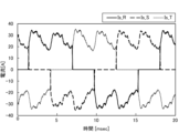
- FIG. 10 is a waveform diagram of three-phase power supply currents when motor harmonic currents are in phase with the power supply harmonic currents of a power conversion device according to a comparative example.
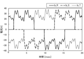
- FIG. 4 is a waveform diagram of three-phase power supply currents when a motor harmonic current is in opposite phase to a power supply harmonic current of the power conversion device according to the first embodiment.
- FIG. 10 is a waveform diagram of a current of a DC reactor when a motor harmonic current is in phase with a power supply harmonic current of a power conversion device according to a comparative example.
- FIG. 4 is a waveform diagram of a current of a DC reactor when a motor harmonic current is in opposite phase to a power supply harmonic current of the power conversion device according to the first embodiment.
- FIG. FIG. 11 is a waveform diagram of three-phase motor currents when motor harmonic currents are in phase with each other relative to power supply harmonic currents of a power conversion device according to a comparative example.
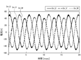
- FIG. 4 is a waveform diagram of three-phase motor currents in a case where motor harmonic currents are in opposite phase to power supply harmonic currents in the power conversion device according to the first embodiment.
- FIG. 11A and 11B are diagrams illustrating results of high-frequency analysis of a power supply current of an R phase in the power conversion devices according to the first embodiment and the comparative example.
- 11 is a diagram showing the results of high-frequency analysis of a current I_DCL of a DC reactor in the power conversion devices according to the first embodiment and the comparative example.
- FIG. FIG. 2 is a configuration diagram of a power conversion device according to a first modified example of the first embodiment.
- FIG. 11 is a configuration diagram of a power conversion device according to a second modified example of the first embodiment.
- FIG. 11 is an explanatory diagram including a control device for a power conversion device according to a second embodiment.
- FIG. 11 is an explanatory diagram showing a relationship between a first rotation speed command and a second rotation speed command in a power conversion device according to a second embodiment.
- FIG. 11 is a configuration diagram of an air conditioner according to a third embodiment.
- FIG. 1 is a configuration diagram of a power conversion device 100 according to the first embodiment. 1 is a device that converts AC power supplied from an AC power source E1 into DC power, converts the DC power into a predetermined AC power, and outputs the DC power to a motor M1.
- the motor M1 may be, for example, a permanent magnet synchronous motor, or may be another type of motor.
- the power conversion device 100 includes a converter circuit 10, a DC voltage detection unit 20, an inverter circuit 30, power supply current detection units 41 and 42, motor current detection units 51 and 52, a control device 60 (control unit), and a gate drive circuit 70.
- the converter circuit 10 is a circuit that converts the AC voltage applied from the AC power source E1 into a DC voltage. That is, the converter circuit 10 has the function of converting the AC voltage applied from the three-phase AC power source E1 into a DC voltage (a pulsating DC voltage) and smoothing this DC voltage. As shown in FIG. 1, the converter circuit 10 includes a diode bridge circuit 11, a DC reactor 12, and a smoothing capacitor 13.
- the diode bridge circuit 11 is a circuit that performs full-wave rectification, and includes six diodes D1 to D6.
- the diode bridge circuit 11 includes a first leg (not shown, but the same applies below) a second leg, and a third leg, which are "legs" each consisting of a pair of diodes connected in series.
- the first leg includes a pair of diodes D1 and D2 connected in series.
- the cathode of the diode D1 is connected to the positive DC line K1.
- the anode of the diode D1 is connected to the cathode of the other diode D2.
- the anode of the other diode D2 is connected to the negative DC line K2.
- the first, second, and third legs are connected in parallel.
- connection point between diodes D1 and D2 of the first leg is connected to AC power source E1 via R-phase wiring HR.
- the connection point between diodes D3 and D4 of the second leg is connected to AC power source E1 via S-phase wiring HS.
- the connection point between diodes D5 and D6 of the third leg is connected to AC power source E1 via T-phase wiring HT.
- the AC voltage applied from AC power source E1 is converted to a pulsating DC voltage by the diode bridge circuit 11.
- the DC reactor 12 and the smoothing capacitor 13 are elements for smoothing the pulsating DC voltage applied from the diode bridge circuit 11. As shown in FIG. 1, the DC reactor 12 is provided on the positive DC line K1. More specifically, the DC reactor 12 is provided on the positive DC line K1 between the connection point between the DC line K1 and the smoothing capacitor 13 and the diode bridge circuit 11.
- the smoothing capacitor 13 is connected to a pair of DC lines K1, K2 on the output side of the diode bridge circuit 11. That is, one end (one lead wire) of the smoothing capacitor 13 is connected to the positive DC line K1, and the other end (the other lead wire) is connected to the negative DC line K2.
- a film capacitor or an electrolytic capacitor is used as such a smoothing capacitor 13.
- film capacitors Compared to electrolytic capacitors, film capacitors have a smaller capacitance per unit volume but a larger rated ripple current. Therefore, compared to electrolytic capacitors, film capacitors can be used with a lower capacitance, making them less expensive, and furthermore, the circuit board (not shown) of the power conversion device 100 can be made smaller. Film capacitors also have the advantage of having a long life. However, when a film capacitor is used as the smoothing capacitor 13, the small capacitance makes it easier for harmonic currents to occur on the AC power source E1 side. Therefore, in the first embodiment, the control device 60 controls the inverter circuit 30 in a predetermined manner to suppress harmonic currents on the power source side. Note that the type of smoothing capacitor 13 is not limited to a film capacitor, and other types of capacitors may be used.
- the output side of the converter circuit 10 is connected to the inverter circuit 30 via a pair of DC lines K1, K2.
- the DC voltage detection unit 20 detects the DC voltage between the pair of DC lines K1, K2.
- the DC voltage between the DC lines K1, K2 may be divided by a series connection of multiple resistance elements (not shown), and the DC voltage between the DC lines K1, K2 may be detected based on the voltage division ratio or the voltage of a predetermined resistance element.
- the momentary detection value of the DC voltage detection unit 20 is output to the control device 60.
- the inverter circuit 30 is a circuit that converts the DC voltage on the output side of the converter circuit 10 into an AC voltage and applies this AC voltage to the motor M1.
- the inverter circuit 30 has a first leg (not shown, same below), a second leg, and a third leg as "legs" configured with a pair of switching elements connected in series. These first leg, second leg, and third leg are connected in parallel to the smoothing capacitor 13.
- the first leg is configured to include a pair of switching elements S1, S2 connected in series.
- the second leg and the third leg are configured similarly.
- IGBTs Insulated Gate Bipolar Transistors
- MOSFETs Metal-Oxide-Semiconductor Field-Effect Transistors
- connection point between the pair of switching elements S1 and S2 is connected to the U-phase winding of the motor M1 via a wiring HU.
- connection point between the switching elements S3 and S4 is connected to the V-phase winding of the motor M1 via a wiring HV.
- connection point between the switching elements S5 and S6 is connected to the W-phase winding of the motor M1 via a wiring HW.
- a free wheel diode (not shown) is connected in inverse parallel to each of the switching elements S1 to S6. Note that if the switching elements S1 to S6 have a parasitic diode (not shown), the parasitic diode functions as the free wheel diode, so there is no need to provide a separate free wheel diode.
- the power supply current detection units 41 and 42 detect the power supply current flowing through the wiring HR, HS, and HT (connecting lines) that connect the AC power supply E1 and the converter circuit 10.
- the power supply current detection unit 41 detects the R-phase power supply current
- another power supply current detection unit 42 detects the S-phase power supply current.
- the momentary detection values of the power supply current detection units 41 and 42 are output to the control device 60.
- the motor current detection units 51 and 52 detect the current in the windings of the motor M1.
- the motor current detection unit 51 detects the motor current of the U phase
- another motor current detection unit 52 detects the AC current of the V phase.
- the moment-to-moment detection values of the motor current detection units 51 and 52 are output to the control device 60.
- the control device 60 has the function of controlling the inverter circuit 30 via the gate drive circuit 70.
- a microcomputer is used as such a control device 60.
- the microcomputer is configured to include electronic circuits such as a CPU (Central Processing Unit), ROM (Read Only Memory), RAM (Random Access Memory), and various interfaces, and reads out programs stored in the ROM and expands them into the RAM, and the CPU executes various processes.
- CPU Central Processing Unit
- ROM Read Only Memory
- RAM Random Access Memory
- the control device 60 generates a predetermined PWM signal (Pulse Width Modulation) based on the detection values of the DC voltage detection unit 20, the power supply current detection units 41, 42, and the motor current detection units 51, 52. Note that the method of generating a PWM signal is well known, so a description thereof will be omitted.
- the PWM signal generated by the control device 60 is output to the gate drive circuit 70.
- the gate drive circuit 70 applies a predetermined voltage to each gate of the switching elements S1 to S6 based on the PWM signal from the control device 60. This switches the switching elements S1 to S6 on and off in a predetermined manner, and applies an AC voltage to the three-phase windings of the motor M1, driving the motor M1.
- ⁇ About harmonic current> As described above, in the converter circuit 10, the AC voltage is rectified to a DC voltage (full-wave rectification in the configuration of FIG. 1). Then, as the power conversion of the converter circuit 10 proceeds, a current having a waveform in which a plurality of harmonic components are superimposed on a sine-wave fundamental wave is generated in the wiring HR, HS, and HT on the power supply side and the DC lines K1 and K2.
- the current of harmonic components accompanying the power conversion of the converter circuit 10 is called a "power supply harmonic current".
- n-th power supply harmonic current a sine-wave power supply harmonic current that changes at a frequency n times (n is an integer of 3 or more) the fundamental wave of the power supply frequency (50 [Hz] or 60 [Hz]) is called an "n-th power supply harmonic current". Also, the frequency of the fundamental wave is called a "fundamental frequency”.
- rectification is performed in the converter circuit 10, so that 5th, 7th, 11th, 13th, 17th, 19th, 23rd, 25th, ... power supply harmonic currents are generated in the wiring HR, HS, and HT, with the power supply frequency of 50 Hz or 60 Hz as the fundamental frequency.
- the orders of these power supply harmonic currents are mathematically derived based on the configuration of the converter circuit 10, etc.
- the power supply harmonic currents caused by the power conversion of the converter circuit 10 appear as power supply harmonic currents of integer multiples of 6, such as 6th, 12th, 18th, 24th, etc., with a power supply frequency of 50 Hz or 60 Hz as the fundamental frequency.
- the 5th and 7th power supply harmonic currents in the power supply side wiring HR, HS, and HT appear as 6th power supply harmonic currents in the DC lines K1 and K2.
- the 11th and 13th power supply harmonic currents in the power supply side wiring HR, HS, and HT appear as 12th power supply harmonic currents in the DC lines K1 and K2.
- the lower the power supply harmonic current the larger the current value tends to be.
- the power supply frequency (i.e., fundamental frequency) of the AC power supply E1 is fs
- the frequency fsh of the power supply harmonic current in the DC lines K1 and K2 is expressed by the following formula (1). Note that x in formula (1) is a natural number.
- the inverter circuit 30 and motor M1 are also sources of harmonic current. That is, as the inverter circuit 30 and motor M1 are driven, a current with a waveform in which multiple harmonic components are superimposed on a sinusoidal fundamental wave is generated in the wiring HU, HV, and HW on the motor M1 side and in the DC lines K1 and K2. In this way, the current with harmonic components that accompanies the drive of the inverter circuit 30 and motor M1 is called the "motor harmonic current.”
- motor harmonic currents are generated in wiring HU, HV, HW on the motor M1 side.
- the orders of these motor harmonic currents are mathematically derived based on the configuration of inverter circuit 30 and motor M1, etc.
- the fundamental frequency is the electrical angular frequency of the motor M1
- the harmonic currents appear as motor harmonic currents of integer multiples of 6, such as 6th, 12th, 18th, 24th, etc.
- the 5th and 7th motor harmonic currents in the wiring HU, HV, and HW on the motor M1 side appear as 6th motor harmonic currents in the DC lines K1 and K2.
- the 11th and 13th motor harmonic currents in the wiring HU, HV, and HW on the motor M1 side appear as 12th motor harmonic currents in the DC lines K1 and K2.
- the lower the motor harmonic current the larger its current value tends to be.
- power supply harmonic currents are generated as a result of power conversion in the converter circuit 10, while motor harmonic currents are also generated as the inverter circuit 30 and motor M1 are driven.
- a current with a predetermined waveform in which the power supply harmonic currents and motor harmonic currents are superimposed on the fundamental wave flows through the DC lines K1 and K2 and the wiring HR, HS, and HT on the power supply side.
- the control device 60 adjusts the rotation speed and current phase of the motor M1 so that the power supply harmonic current is reduced by the motor harmonic current.
- the motor harmonic current may be configured to completely cancel out the power supply harmonic current of a predetermined order, or the power supply harmonic current may be reduced (partially canceled out).
- the control device 60 makes the frequency of the motor harmonic current of a predetermined order match the power supply harmonic current of a predetermined order.
- the control device 60 makes the frequency fsh of the power supply harmonic current in the above formula (1) equal to the frequency fmh of the motor harmonic current in formula (2). This relationship is expressed by the following formula (3).
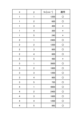
- FIG. 2 is an explanatory diagram including examples of numerical values of rotation speeds of motors that are candidates for suppressing power supply harmonic currents (also refer to FIG. 1 as necessary).
- the rotation speed fm of the motor M1 within the range of 600 to 7000 [min -1 ] is marked with a " ⁇ "
- the rotation speed fm outside this range is marked with an "X”.
- x and y shown in Fig. 2 correspond to the natural numbers x and y included in formula (4).
- fm shown in Fig. 2 corresponds to the rotation speed fm of the motor M1 included in formula (4).
- the value of the rotation speed fm of the motor M1 is 1200 [min -1 ].
- the order of the power supply harmonic current (six times the natural number x) and the order of the motor harmonic current (six times the natural number y) are both 6th order.
- the value of the rotation speed fm of the motor M1 is 600 [min -1 ].
- the order of the power supply harmonic current is 6th order
- the order of the motor harmonic current is 12th order. In this way, there are multiple cases where the formula (4) is true.
- FIG. 3 is an explanatory diagram showing the relationship between the frequency of the power supply harmonic current, the rotation speed of the motor, and the frequency of the motor harmonic current.
- the explanatory diagram in Fig. 3 corresponds to the table in Fig. 2.
- the numbers enclosed in a thick frame in Fig. 3 indicate that the frequency of the power supply harmonic current is equal to the frequency of the motor harmonic current.
- the "order" in Fig. 3 indicates the order of the power supply harmonic current and the motor harmonic current.
- the power supply frequency is 60 [Hz]
- the frequencies of the motor harmonic current are 360 [Hz] for the 6th harmonic, 720 [Hz] for the 12th harmonic, 1080 [Hz] for the 18th harmonic, 1440 [Hz] for the 24th harmonic, and 1800 [Hz] for the 30th harmonic.
- the frequencies of the power supply harmonic current are 360 [Hz] for the 6th harmonic, 720 [Hz] for the 12th harmonic, 1080 [Hz] for the 18th harmonic, 1440 [Hz] for the 24th harmonic, and 1800 [Hz] for the 30th harmonic.
- the values of the orders of the motor harmonic current and the power supply harmonic current are mutually consistent.
- the frequencies of the motor harmonic current are 180 [Hz] for the 6th harmonic, 360 [Hz] for the 12th harmonic, 540 [Hz] for the 18th harmonic, 720 [Hz] for the 24th harmonic, and 900 [Hz] for the 30th harmonic.
- the order of each harmonic when the frequency of the motor harmonic current matches the frequency of the power supply harmonic current differs depending on the rotation speed of the motor M1.
- the rotation speed of the motor M1 is set to 1200 [min -1 ]
- the frequency of the motor harmonic current matches the frequency of the power supply harmonic current at each order, but otherwise the frequencies match at some orders.
- the control device 60 (see FIG. 1) therefore adjusts the rotation speed of the motor M1 so that the frequencies of the power supply harmonic current and the motor harmonic current match at a predetermined order, and further adjusts the current phase of the motor M1 so that the motor harmonic current is in opposite phase to the phase of the power supply harmonic current.
- the power supply harmonic current is at least partially cancelled out by the motor harmonic current, and the power supply harmonic current can be reduced.
- the rotation speed of the motor M1 when the power supply harmonic current is reduced by the motor harmonic current is set based on the frequency of the AC power supply E1 and the number of poles of the motor M1. Which of the 11 rotation speed candidates shown in FIG. 3 the control device 60 uses as the rotation speed specification value of the motor M1 is appropriately set based on the operating conditions of the motor M1, etc.
- the control device 60 changes the current phase of the motor M1 while driving the motor M1 at a predetermined rotation speed, and adjusts the current phase of the motor M1 based on the detection values of the power supply current detection units 41, 42 (see FIG. 1) so as to reduce the harmonic components contained in the detection values. For example, the control device 60 calculates the effective value of the current on which multiple harmonic components are superimposed after removing the fundamental wave components from each detection value of the power supply current detection units 41, 42 (see FIG. 1). The control device 60 then repeats the process of changing the current phase at a predetermined pitch and calculating the effective value of the current (current on which multiple harmonic components are superimposed). The control device 60 then drives the motor M1 with a current phase that minimizes the effective value of the current. In this case, the power supply harmonic current is reduced by the motor harmonic current.
- control device 60 As another method for the control device 60 to adjust the current phase of the motor M1, high-frequency analysis based on the discrete Fourier transform (FFT: Fast Fourier Transformation) may be used. In this case, the control device 60 drives the motor M1 with the current phase when the value of the power supply harmonic current of a predetermined order is minimized.
- FFT discrete Fourier transform
- control device 60 adjusts the rotation speed and current phase of the motor M1 so as to reduce the power supply harmonic current associated with the power conversion of the converter circuit 10 by the motor harmonic current associated with the drive of the inverter circuit 30 and the motor M1.
- This makes it possible to reduce the power supply harmonic current, allowing operation in compliance with power supply harmonic regulations and preventing failures and malfunctions of equipment (not shown) connected to the AC power supply E1.
- FIG. 4A is a waveform diagram of three-phase power supply currents Is_R, Is_S, and Is_T when the motor harmonic currents are in phase with the power supply harmonic currents of the power conversion device according to the comparative example.
- the motor harmonic current is in phase with the power supply harmonic current, and the comparison is the same as the first embodiment.
- the power supply voltage of the AC power supply E1 (see Fig. 1) is 200 [V], 60 [Hz]
- the inductance of the DC reactor 12 (see Fig. 1) is 0.136 [mH]
- the capacitance of the smoothing capacitor 13 is 90 [ ⁇ F].
- the rotation speed of the motor M1 is 4800 [min -1 ]
- the number of poles of the motor M1 is 6 poles (i.e., the number of pole pairs is 3 pole pairs).
- the power supply harmonic current will be amplified by the motor harmonic current, and the three-phase power supply currents Is_R, Is_S, and Is_T will have steep waveforms as shown in the comparative example in Figure 4A.
- FIG. 4B is a waveform diagram of three-phase power supply currents Is_R, Is_S, and Is_T when the motor harmonic currents are in opposite phase to the power supply harmonic currents of the power conversion device according to the first embodiment.
- conditions such as the power supply voltage, the number of poles of the motor M1, and the rotation speed are the same as those in FIG. 4A (the same applies to FIGS. 5A, 5B, 6A, 6B, 7A, and 7B).
- the 24th power supply harmonic current is cancelled out by the 6th motor harmonic current. Therefore, in the waveform diagram of Figure 4B, the three-phase power supply currents Is_R, Is_S, and Is_T have rounder waveforms compared to the comparative example of Figure 4A. Note that whether the 24th power supply harmonic current has actually been reduced can be determined by frequency analysis of the power supply current (see Figure 7B).
- FIG. 5A is a waveform diagram of a current I_DCL of a DC reactor when a motor harmonic current is in phase with a power supply harmonic current of a power conversion device according to a comparative example.
- the power supply harmonic current is amplified by the motor harmonic current, and the current I_DCL of the DC reactor 12 (see FIG. 1) has a steep waveform as shown in the comparative example of FIG. 5A.
- FIG. 5B is a waveform diagram of the current I_DCL of the DC reactor when the motor harmonic current is in antiphase with respect to the power supply harmonic current of the power conversion device according to the first embodiment.
- the sixth-order motor harmonic current is in opposite phase to the aforementioned twenty-fourth-order power supply harmonic current, the sixth-order motor harmonic current cancels out the twenty-fourth-order power supply harmonic current. Therefore, in the waveform diagram of Fig. 5B, the current I_DCL of the DC reactor 12 (see Fig. 1) has a rounder waveform than the comparative example of Fig. 5A.
- FIG. 6A is a waveform diagram of three-phase motor currents Im_U, Im_V, and Im_W when the motor harmonic currents are in phase with the power supply harmonic currents of the power conversion device according to the comparative example.
- three different phase motor currents Im_U, Im_V, and Im_W flow through the windings of the motor M1.
- Each of the motor currents Im_U, Im_V, and Im_W contains a predetermined harmonic component.
- FIG. 6B is a waveform diagram of three-phase motor currents Im_U, Im_V, and Im_W when the motor harmonic currents are in opposite phase to the power supply harmonic currents of the power conversion device according to the first embodiment.
- the manner in which the motor currents Im_U, Im_V, and Im_W shown in Fig. 6B change is similar to that in the comparative example in Fig. 6A, but the phases of the motor currents Im_U, Im_V, and Im_W are different from those in the comparative example. This is because the current phase of the motor M1 is adjusted so that the 6th-order motor harmonic current is in the opposite phase to the 24th-order power supply harmonic current described above.
- FIG. 7A is a diagram showing the results of high-frequency analysis of the R-phase power supply current in the power conversion devices according to the first embodiment and the comparative example.
- the horizontal axis of Fig. 7A is frequency
- the vertical axis is high-frequency content.
- the solid line shows the result of high-frequency analysis when the motor harmonic current is in phase with the power supply harmonic current (first embodiment).
- the dashed line shows the result of high-frequency analysis when the motor harmonic current is in phase with the power supply harmonic current (comparative example).
- the result of high-frequency analysis shown in Fig. 7A is based on the data in Figs. 4A, 4B, 5A, 5B, 6A, and 6B.
- discrete Fourier transform FFT
- the power supply harmonic current contained in the power supply current is reduced, particularly at 1380 [Hz] (the frequency of the 23rd power supply harmonic current).
- the power supply harmonic current is also reduced at 1500 [Hz], which is the frequency of the 25th power supply harmonic current.
- the 24th power supply harmonic current (1440 [Hz]: see FIG. 3) in the DC lines K1 and K2 (see FIG. 1) appears as the 23rd and 25th power supply harmonic currents in the power supply side wiring HR (see FIG. 1).
- the power supply harmonic currents near 1380 [Hz] and 1500 [Hz] are reduced compared to the case where no phase adjustment of the motor current is performed.
- FIG. 7B is a diagram showing the results of high-frequency analysis of the current I_DCL of the DC reactor in the power conversion devices according to the first embodiment and the comparative example.
- the horizontal and vertical axes in Fig. 7B are the same as those in Fig. 7A.
- the power supply harmonic current included in the current I_DCL of the DC reactor 12 is reduced, particularly at 1440 [Hz] (the frequency of the 24th power supply harmonic current: see Fig. 3).
- ⁇ Effects> it is possible to reduce the power supply harmonic current even when a low-cost, long-life film capacitor is used as the smoothing capacitor 13. This makes it possible to prevent failure or malfunction of equipment (not shown) connected to the AC power supply E1, and also allows operation in compliance with power supply harmonic regulations.
- the smoothing capacitor 13 when a film capacitor is used as the smoothing capacitor 13, the smaller capacitance increases the resonant frequency between the smoothing capacitor 13 and the DC reactor 12. As a result, the power supply harmonic current with a frequency close to this resonant frequency also tends to increase. Even in such a case, as described above, the power supply harmonic current is reduced by the motor harmonic current, so that failure or malfunction of equipment (not shown) connected to the AC power supply E1 can be prevented.
- the parameters that are adjusted when reducing the power supply harmonic current are the rotation speed and current phase of the motor M1. Therefore, compared to before the adjustment of the rotation speed and current phase, there is almost no distortion of the waveform of the motor current, and therefore the decrease in efficiency of the motor M1 can be suppressed. In this way, according to the first embodiment, it is possible to reduce the power supply harmonic current while suppressing the decrease in efficiency. Furthermore, since there is no particular distortion of the waveform of the motor current, fluctuations in the rotation speed of the motor M1 are suppressed. As a result, noise associated with the operation of the motor M1 can also be suppressed.
- FIG. 8 is a configuration diagram of a power conversion device 100A according to a first modified example of the first embodiment. 8 is different from the first embodiment (see FIG. 1) in that the power conversion device 100A includes a DC line current detection unit 80, but is otherwise similar to the first embodiment. Therefore, only the parts that are different from the first embodiment will be described, and a description of the overlapping parts will be omitted.
- the DC line current detection unit 80 shown in FIG. 8 detects the current flowing in the DC line K1 on the output side of the converter circuit 10, and is provided on the DC line K1. The momentary detection value of the DC line current detection unit 80 is output to the control device 60.
- control device 60 changes the current phase of the motor M1 while driving the motor M1 at a predetermined rotation speed. Then, based on the detection value of the DC line current detection unit 80, the control device 60 adjusts the current phase of the motor M1 so as to reduce the harmonic components of this detection value. With this method as well, it is possible to identify the current phase of the motor M1 that can reduce a predetermined order of power supply harmonic current.
- the harmonic components of the current in the DC line K1 also appear as certain harmonic components in the wiring HR, HS, and HT on the power supply side. Therefore, when the harmonic components of the current in the DC line K1 are reduced, the power supply harmonic current is also reduced.
- FIG. 9 is a configuration diagram of a power conversion device 100B according to a second modification of the first embodiment. 9 is different from the first embodiment (see FIG. 1) in that the power conversion device 100B includes a DC reactor voltage detection unit 90, but is otherwise similar to the first embodiment. Therefore, only the parts that are different from the first embodiment will be described, and a description of the overlapping parts will be omitted.
- the DC reactor voltage detection unit 90 shown in FIG. 9 detects the terminal voltage of the DC reactor 12 provided on the DC line K1 on the output side of the converter circuit 10, and is connected to each terminal of the DC reactor 12. The momentary detection value of the DC reactor voltage detection unit 90 is output to the control device 60.
- control device 60 changes the current phase of the motor M1 while driving the motor M1 at a predetermined rotation speed. Then, based on the detection value of the DC reactor voltage detection unit 90, the control device 60 adjusts the current phase of the motor M1 so as to reduce the harmonic components of this detection value. With this method as well, it is possible to identify the current phase of the motor M1 that can reduce a power supply harmonic current of a predetermined order.
- the second embodiment differs from the first embodiment in that a control device 60C (see FIG. 10) includes a rotation speed command regulator 61 (see FIG. 10).
- the rest of the second embodiment is similar to the first embodiment. Therefore, only the parts that are different from the first embodiment will be described, and the description of the overlapping parts will be omitted.
- FIG. 10 is an explanatory diagram including a control device 60C of a power conversion device according to the second embodiment.
- the control device 60C includes a rotation speed command regulator 61.
- the rotation speed command regulator 61 i.e., a control unit
- a command value (first rotation speed command) for the rotation speed of motor M1 is set based on various conditions such as the operating mode, temperature and air volume settings, as well as the detected values of outside air temperature and room temperature. Therefore, in the second embodiment, when the absolute value of the deviation between the rotation speed of motor M1 that can reduce the power supply harmonic current by the motor harmonic current and the first rotation speed command is equal to or less than a predetermined value, the rotation speed command regulator 61 (i.e., the control unit) sets this rotation speed as the second rotation speed command. Motor M1 is driven based on this second rotation speed command.
- the rotation speed command regulator 61 i.e., the control unit
- the predetermined value e.g., 100 [min ⁇ 1 ]
- the predetermined value is a threshold value that serves as a criterion for determining whether or not to set the second rotation speed command at a value different from the first rotation speed command, and is set in advance.
- FIG. 11 is an explanatory diagram showing the relationship between the first rotation speed command and the second rotation speed command.
- the horizontal axis of Fig. 11 indicates the value of the first rotation speed command for the motor M1 (see Fig. 1).
- the vertical axis of Fig. 11 indicates the value of the second rotation speed command for the motor M1.
- Values F1 and F2 shown in Fig. 11 are rotation speeds of the motor M1 that can reduce the power supply harmonic current by the motor harmonic current. These values F1 and F2 are stored in advance in the control device 60 based on the power supply frequency and the number of poles of the motor M1.
- the broken line G1 shown in FIG. 11 is a function used to convert the first rotation speed command to the second rotation speed command, and is stored in advance in the control device 60C (see FIG. 10). Note that a predetermined data table may be set instead of the function shown by the broken line G1.
- the rotation speed command regulator 61 sets the second rotation speed command to a value F1.
- the rotation speed command regulator 61 sets the value F1 as the second rotation speed command.
- the rotation speed command regulator 61 sets the second rotation speed command to a value F2. This makes it possible to expand the operating range (the range of the first rotation speed command) in which the motor harmonic current can cancel out the power supply harmonic current.
- the rotation speed command regulator 61 sets the same value as the first rotation speed command as the second rotation speed command. This makes it possible to prevent the operation of equipment such as an air conditioner from deviating from its original purpose (air conditioning). For example, when the temperature inside the room is high in summer, it becomes possible to prioritize cooling operation over reducing the power supply harmonic current, and to drive the compressor motor M1 at high speed.
- the second embodiment it is possible to expand the operating range (range of the first rotation speed command) in which the power supply harmonic current can be cancelled by the motor harmonic current. Furthermore, the process of reducing the power supply harmonic current is not uniformly performed, but the second rotation speed command can be appropriately set based on the deviation between the first rotation speed command and the values F1 and F2.
- an air conditioner W1 including the power conversion device 100 (see FIG. 1) configured as described in the first embodiment will be described. Note that the configuration and processing contents of the power conversion device 100 (see FIG. 1) are similar to those in the first embodiment, and therefore description thereof will be omitted.
- FIG. 12 is a configuration diagram of an air conditioner W1 according to the third embodiment.
- the solid arrows in FIG. 12 indicate the flow of the refrigerant in the heating cycle.
- the dashed arrows in FIG. 12 indicate the flow of refrigerant in the cooling cycle.
- the air conditioner W1 is a device that performs air conditioning such as cooling operation and heating operation. As shown in Fig. 12, the air conditioner W1 includes, as components provided in the outdoor unit U1, a compressor 91 (device), an outdoor heat exchanger 92, an outdoor fan 93, an expansion valve 94, and a four-way valve 95.
- the air conditioner W1 also includes, as components provided in the indoor unit U2, an indoor heat exchanger 96 and an indoor fan 97.
- the air conditioner W1 is equipped with the power conversion device 100 (see FIG. 1) described in the first embodiment.
- the power conversion device 100 (see FIG. 1) is mounted on a circuit board (not shown) of the outdoor unit U1.
- the compressor 91 is a "device” that compresses a low-temperature, low-pressure gas refrigerant and discharges it as a high-temperature, high-pressure gas refrigerant.
- an accumulator for separating the refrigerant into gas and liquid is connected to the suction side of the compressor 91.
- the motor M1 which is the drive source of the compressor 91, is electrically connected to the output side of the inverter circuit 30 (see FIG. 1) of the power conversion device 100 (see FIG. 1).
- the outdoor heat exchanger 92 is a heat exchanger in which heat is exchanged between the refrigerant flowing through its heat transfer tube and the outside air sent in from the outdoor fan 93.
- the outdoor fan 93 is a fan that sends outside air to the outdoor heat exchanger 92.
- the outdoor fan 93 has an outdoor fan motor 93a as its driving source, and is installed near the outdoor heat exchanger 92.
- the expansion valve 94 is a valve that reduces the pressure of the refrigerant condensed in the "condenser" (one of the outdoor heat exchanger 92 and the indoor heat exchanger 96).
- the refrigerant reduced in pressure by the expansion valve 94 is guided to the "evaporator" (the other of the outdoor heat exchanger 92 and the indoor heat exchanger 96).
- the indoor heat exchanger 96 is a heat exchanger in which heat is exchanged between the refrigerant flowing through its heat transfer tube (not shown) and indoor air (air in the air-conditioned room) sent in by an indoor fan 97 .
- the indoor fan 97 is a fan that sends indoor air to the indoor heat exchanger 96.
- the indoor fan 97 includes an indoor fan motor 97a as a drive source, and is installed near the indoor heat exchanger 96.
- the four-way valve 95 is a valve that switches the flow path of the refrigerant depending on the operating mode of the air conditioner W1. For example, during cooling operation (see the dashed arrow in FIG. 12), the refrigerant circulates in the refrigerant circuit Q1 through the compressor 91, the outdoor heat exchanger 92 (condenser), the expansion valve 94, and the indoor heat exchanger 96 (evaporator) in that order. Also, during heating operation (see the solid arrow in FIG. 12), the refrigerant circulates in the refrigerant circuit Q1 through the compressor 91, the indoor heat exchanger 96 (condenser), the expansion valve 94, and the outdoor heat exchanger 92 (evaporator) in that order. Then, the air that has exchanged heat with the refrigerant flowing through the indoor heat exchanger 96 is blown out from the indoor unit U2 into the air-conditioned room.
- the air conditioner W1 is equipped with a power conversion device 100 (see Figure 1) having a configuration similar to that of the first embodiment, so that a highly reliable air conditioner W1 capable of reducing power supply harmonic currents can be provided.
- the power conversion device 100 and the air conditioner W1 according to the present disclosure have been described in each embodiment above, they are not limited to these descriptions and various modifications can be made.
- the converter circuit 10 (see FIG. 1) is described as including a diode bridge circuit 11 (see FIG. 1) for full-wave rectification, but the present invention is not limited to this.
- the converter circuit may include a voltage doubler rectifier circuit.
- a switching type converter circuit may be used. The same can be said about the second embodiment.
- the smoothing capacitor 13 in the first embodiment, the case where there is one smoothing capacitor 13 (see FIG. 1) has been described, but this is not limited to this.
- the smoothing capacitor may be formed by multiple capacitors (not shown) connected in series, parallel, or series-parallel. The same can be said about the second embodiment.
- the control device 60 reduces the power supply harmonic current by using the motor harmonic current.
- other methods capable of reducing the power supply harmonic current may be used in combination as appropriate.
- the power supply frequency is 60 [Hz] and the number of poles of the motor M1 is six has been described, but this is not limited thereto. That is, the power conversion device 100 may be used under conditions of another power supply frequency (e.g., 50 [Hz]).
- the motor M1 may have another number of poles, such as four poles or eight poles. The same can be said about the second embodiment.
- the power conversion device 100 is connected to the motor M1 of the compressor 91, but the present invention is not limited to this.
- the power conversion device 100 may be connected to the outdoor fan motor 93a.
- the power conversion device 100 may be connected to the motor M1 of the compressor 91, and the power conversion device 100 may be connected to the outdoor fan motor 93a.
- the air conditioner W1 is provided with the four-way valve 95, but the present invention is not limited to this. That is, the four-way valve 95 may be omitted as appropriate to make the air conditioner a cooling-only or heating-only air conditioner.
- the third embodiment can be applied to various types of air conditioners such as commercial air conditioners and multi-air conditioners for buildings, in addition to room air conditioners. Each embodiment can also be applied to other devices such as water heaters and refrigerators. In addition, the respective embodiments can be appropriately combined. For example, the second embodiment (see FIG. 10 and FIG. 11) and the third embodiment (see FIG. 12) can be combined.
Landscapes
- Engineering & Computer Science (AREA)
- Power Engineering (AREA)
- Control Of Ac Motors In General (AREA)
Priority Applications (2)
| Application Number | Priority Date | Filing Date | Title |
|---|---|---|---|
| JP2025560510A JPWO2025115215A1 (https=) | 2023-12-01 | 2023-12-01 | |
| PCT/JP2023/043120 WO2025115215A1 (ja) | 2023-12-01 | 2023-12-01 | 電力変換装置及び空気調和機 |
Applications Claiming Priority (1)
| Application Number | Priority Date | Filing Date | Title |
|---|---|---|---|
| PCT/JP2023/043120 WO2025115215A1 (ja) | 2023-12-01 | 2023-12-01 | 電力変換装置及び空気調和機 |
Publications (1)
| Publication Number | Publication Date |
|---|---|
| WO2025115215A1 true WO2025115215A1 (ja) | 2025-06-05 |
Family
ID=95896369
Family Applications (1)
| Application Number | Title | Priority Date | Filing Date |
|---|---|---|---|
| PCT/JP2023/043120 Pending WO2025115215A1 (ja) | 2023-12-01 | 2023-12-01 | 電力変換装置及び空気調和機 |
Country Status (2)
| Country | Link |
|---|---|
| JP (1) | JPWO2025115215A1 (https=) |
| WO (1) | WO2025115215A1 (https=) |
Citations (5)
| Publication number | Priority date | Publication date | Assignee | Title |
|---|---|---|---|---|
| CN1529404A (zh) * | 2003-09-26 | 2004-09-15 | 勇 谭 | 用于高压变频的三相分裂式移相变压器及其应用 |
| JP2007205687A (ja) * | 2006-02-06 | 2007-08-16 | Mitsubishi Electric Corp | 空気調和機の電源システム |
| US20140312823A1 (en) * | 2011-12-20 | 2014-10-23 | Exxonmobil Upstream Research Company | Harmonics Suppression in a Power Delivery Device |
| JP2019037106A (ja) * | 2017-08-22 | 2019-03-07 | 株式会社明電舎 | 電力変換器の制御装置 |
| CN116436274A (zh) * | 2023-05-24 | 2023-07-14 | 中冶京诚工程技术有限公司 | 变频器电源侧的谐波抵消方法及装置 |
-
2023
- 2023-12-01 WO PCT/JP2023/043120 patent/WO2025115215A1/ja active Pending
- 2023-12-01 JP JP2025560510A patent/JPWO2025115215A1/ja active Pending
Patent Citations (5)
| Publication number | Priority date | Publication date | Assignee | Title |
|---|---|---|---|---|
| CN1529404A (zh) * | 2003-09-26 | 2004-09-15 | 勇 谭 | 用于高压变频的三相分裂式移相变压器及其应用 |
| JP2007205687A (ja) * | 2006-02-06 | 2007-08-16 | Mitsubishi Electric Corp | 空気調和機の電源システム |
| US20140312823A1 (en) * | 2011-12-20 | 2014-10-23 | Exxonmobil Upstream Research Company | Harmonics Suppression in a Power Delivery Device |
| JP2019037106A (ja) * | 2017-08-22 | 2019-03-07 | 株式会社明電舎 | 電力変換器の制御装置 |
| CN116436274A (zh) * | 2023-05-24 | 2023-07-14 | 中冶京诚工程技术有限公司 | 变频器电源侧的谐波抵消方法及装置 |
Also Published As
| Publication number | Publication date |
|---|---|
| JPWO2025115215A1 (https=) | 2025-06-05 |
Similar Documents
| Publication | Publication Date | Title |
|---|---|---|
| US8164292B2 (en) | Motor controller of air conditioner | |
| KR101564727B1 (ko) | 공기조화기 | |
| CN115173720A (zh) | 电磁兼容性滤波器 | |
| JP2003174779A (ja) | 電力変換装置 | |
| CN116670995B (zh) | 电力转换装置、马达驱动装置以及制冷循环应用设备 | |
| CN100521504C (zh) | 用于增加电机中的输出马力和效率的系统和方法 | |
| CN116420302B (zh) | 电力转换装置、马达驱动装置以及制冷循环应用设备 | |
| WO2022149207A1 (ja) | 電力変換装置、モータ駆動装置及び冷凍サイクル適用機器 | |
| EP2073373A2 (en) | Method for controlling motor of air conditioner | |
| WO2022172419A1 (ja) | 電力変換装置、モータ駆動装置および空気調和機 | |
| KR20100102965A (ko) | 공기조화기의 전동기 구동장치 | |
| US11512885B2 (en) | Variable speed drive with secondary windings | |
| WO2025115215A1 (ja) | 電力変換装置及び空気調和機 | |
| JP2016144323A (ja) | 直流電源装置およびこれを用いた空気調和機 | |
| KR20090052167A (ko) | 공기조화기 | |
| WO2022172418A1 (ja) | 電力変換装置、モータ駆動装置および冷凍サイクル適用機器 | |
| JP3296695B2 (ja) | インバータ付き空気調和機 | |
| KR101905480B1 (ko) | 모터 구동장치 및 이를 구비하는 공기조화기 | |
| WO2009064050A2 (en) | Motor controller of air conditioner | |
| KR20100133635A (ko) | 공기조화기의 전동기 구동장치 | |
| KR102010388B1 (ko) | 모터 구동장치 및 이를 구비하는 공기조화기 | |
| JP4200017B2 (ja) | 電気装置 | |
| CN1330248A (zh) | 变频驱动的房间空气调节器 | |
| JP7813967B1 (ja) | 電力変換装置及び空気調和機 | |
| JP7651002B2 (ja) | 電力変換装置およびヒートポンプ装置 |
Legal Events
| Date | Code | Title | Description |
|---|---|---|---|
| 121 | Ep: the epo has been informed by wipo that ep was designated in this application |
Ref document number: 23960232 Country of ref document: EP Kind code of ref document: A1 |
|
| ENP | Entry into the national phase |
Ref document number: 2025560510 Country of ref document: JP Kind code of ref document: A |
|
| WWE | Wipo information: entry into national phase |
Ref document number: 2025560510 Country of ref document: JP |