WO2025115201A1 - 蓄電装置、蓄電装置の制御方法 - Google Patents
蓄電装置、蓄電装置の制御方法 Download PDFInfo
- Publication number
- WO2025115201A1 WO2025115201A1 PCT/JP2023/043024 JP2023043024W WO2025115201A1 WO 2025115201 A1 WO2025115201 A1 WO 2025115201A1 JP 2023043024 W JP2023043024 W JP 2023043024W WO 2025115201 A1 WO2025115201 A1 WO 2025115201A1
- Authority
- WO
- WIPO (PCT)
- Prior art keywords
- secondary battery
- charging
- state
- storage device
- capacity management
- Prior art date
- Legal status (The legal status is an assumption and is not a legal conclusion. Google has not performed a legal analysis and makes no representation as to the accuracy of the status listed.)
- Pending
Links
Images



Classifications
-
- H—ELECTRICITY
- H01—ELECTRIC ELEMENTS
- H01M—PROCESSES OR MEANS, e.g. BATTERIES, FOR THE DIRECT CONVERSION OF CHEMICAL ENERGY INTO ELECTRICAL ENERGY
- H01M10/00—Secondary cells; Manufacture thereof
- H01M10/42—Methods or arrangements for servicing or maintenance of secondary cells or secondary half-cells
- H01M10/48—Accumulators combined with arrangements for measuring, testing or indicating the condition of cells, e.g. the level or density of the electrolyte
Definitions
- the present invention relates to an electricity storage device and a control method thereof.
- a backup power storage device that is connected to a power supply device that supplies power to various electrical devices such as communication devices used in communication base stations, stores the power supplied from the power supply device, and, when the power supply from the power supply device is stopped, supplies power to various electrical devices using the stored power in place of the power supply device.
- Patent Document 1 describes a power supply system that uses a trickle charging method to charge a storage battery with a minute current, in which the storage battery is normally not connected to a load and trickle charges the storage battery with DC power generated by a charging power source based on AC power from a commercial power system, and in the event of a power outage when the AC power from the commercial power system is cut off, the storage battery is connected to the load and DC power is discharged from the storage battery and supplied to the load.
- trickle charging of the storage battery is performed by controlling the voltage during trickle charging to a constant voltage in the range of 1.82 V to 1.86 V, and the current to 0.2 C.
- additional equipment such as a DC/DC converter is required to perform these controls, which poses the problem of increased system implementation costs.
- the present invention aims to provide a power storage device that can be used for purposes such as backing up power supplies and can be introduced at low cost, and a control method for the same.
- the control unit While the secondary battery is being charged, the control unit performs a capacity management process during charging to determine a state of charge of the secondary battery based on an integrated value of the current detected by the current detection unit, and determines whether or not to continue charging of the secondary battery based on the state of charge.
- the control unit performs a capacity management process during charging to determine a state of charge of the secondary battery based on the voltage detected by the voltage detection unit and the temperature detected by the battery temperature detection unit, and determines whether or not to resume charging of the secondary battery based on the state of charge.
- the control unit controls the charging of the secondary battery based on the results of the capacity management process during charging and the capacity management process when charging is stopped.
- a control method for an energy storage device is a control method for an energy storage device that is connected to a power supply equipment, stores power supplied from the power supply equipment in a secondary battery, and, when the operation of the power supply equipment is stopped, supplies the power stored in the secondary battery to other electrical equipment connected to the power supply equipment, wherein, while the secondary battery is being charged, a capacity management process during charging is performed to determine the state of charge of the secondary battery based on an integrated value of the current flowing through the secondary battery, and based on the state of charge, it is determined whether or not to continue charging of the secondary battery, and while charging of the secondary battery is stopped, a capacity management process during charging is performed to determine the state of charge of the secondary battery based on the voltage and temperature of the secondary battery, and based on the state of charge, it is determined whether or not to resume charging of the secondary battery, and the charging of the secondary battery is controlled based on the results of the capacity management process during charging and the capacity management process when charging is stopped.
- the present invention provides a low-cost energy storage device and a method for controlling the same.
- 1 is a schematic configuration diagram of a communication base station including a power storage device according to an embodiment of the present invention
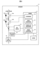
- 1 is a schematic configuration diagram of an electricity storage device according to an embodiment of the present invention
- 5 is a graph showing a specific example of charge/discharge control of a secondary battery.
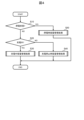
- 4 is a flowchart showing a flow of processing in a power storage device according to an embodiment of the present invention.
- 6 is a flowchart showing details of a charging capacity management process.
- 10 is a flowchart showing details of a capacity management process when charging is stopped.
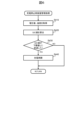
- 11 is a flowchart showing details of a capacity management process during a power outage.
- FIG. 1 is a schematic diagram of a communications base station including a power storage device according to one embodiment of the present invention.
- the communications base station 1 shown in FIG. 1 is a base station for wireless communications used, for example, in a mobile phone network, and includes a power supply facility 10, communications equipment 11, and one or more power storage devices 12.
- the power supply equipment 10 is connected to the power system 2 via a circuit breaker 3, and converts AC power input from the power system 2 into DC power, which is then supplied to the communication equipment 11 and each power storage device 12.
- the power supply equipment 10 is formed by combining, for example, a rectifier and a lead battery.
- the power storage device 12 is provided in the communications base station 1 to back up the power supply equipment 10 in the event of a power outage in the power grid 2.
- the power storage device 12 is connected to the power supply equipment 10, and stores the power supplied from the power supply equipment 10 when the power supply equipment 10 is in operation.
- the power storage device 12 supplies the power stored up to that point to the communications equipment 11. This allows the communications equipment 11 to continue operating even during a power outage.
- the number of storage devices 12 installed in the communication base station 1 can be set arbitrarily depending on the power consumption of the communication equipment 11, the amount of electricity that can be stored per storage device 12, the maximum expected power outage time during a power outage, etc.
- FIG. 2 is a schematic diagram of an energy storage device according to one embodiment of the present invention.
- the energy storage device 12 of this embodiment is configured to include a secondary battery 20, a control unit 21, switches 22a and 22b, diodes 23a and 23b, a voltage detection unit 24, a current detection unit 25, a battery temperature detection unit 26, and a memory unit 27.
- the secondary battery 20 is connected to the power supply equipment 10 and the communication device 11 in FIG. 1 via switches 22a and 22b.
- the secondary battery 20 When power is being supplied from the power supply equipment 10, the secondary battery 20 is charged according to the control of the control unit 21, and power is stored in the secondary battery 20.
- the secondary battery 20 is discharged according to the control of the control unit 21, and power is supplied from the secondary battery 20 to the communication device 11.
- the switches 22a and 22b are provided between the secondary battery 20 and the power supply equipment 10 and the communication device 11, and are each switched to either a conductive state or a cut-off state under the control of the control unit 21.
- the switches 22a and 22b are each configured using, for example, a relay, an IGBT (Insulated Gate Bipolar Transistor), a FET (Field Effect Transistor), or the like. As shown in Figure 2, the switches 22a and 22b are connected in series. The series connection of the switches 22a and 22b constitutes a switching circuit in the energy storage device 12 that can switch the electrical connection between the secondary battery 20 and the power supply equipment 10 and the communication device 11 to either a conductive state or a cut-off state.
- a diode 23a is connected in parallel to the switch 22a. As shown in FIG. 2, the orientation of the diode 23a is set so that it conducts current flowing from the power supply equipment 10 to the secondary battery 20 (charging direction) and blocks current flowing in the opposite direction.
- Diode 23b is connected in parallel to switch 22b. As shown in FIG. 2, diode 23b is oriented in the opposite direction to diode 23a, i.e., in the direction that conducts current flowing from secondary battery 20 to communication device 11 (discharging direction) and blocks current flowing in the opposite direction.
- the charging capacity management unit 211 obtains an SOC value representing the state of charge (SOC) of the secondary battery 20 while the secondary battery 20 is being charged, and manages the capacity of the secondary battery 20 based on this SOC value.
- the charging stop capacity management unit 212 obtains an SOC value when charging of the secondary battery 20 is stopped, and manages the capacity of the secondary battery 20 based on this SOC value.
- the power outage capacity management unit 213 obtains an SOC value of the secondary battery 20 when the operation of the power supply equipment 10 is stopped due to a power outage or the like, and power is not supplied from the power supply equipment 10, and manages the capacity of the secondary battery 20 based on this SOC value.
- the switching control unit 214 controls the switching states of the switches 22a and 22b in response to commands from the charging capacity management unit 211, the charging stop capacity management unit 212, and the power outage capacity management unit 213. The specific contents of these processes will be described later.
- step S370 the charging capacity management unit 211 compares the voltage value of the secondary battery 20 acquired in step S310 with the end-of-charge voltage VH calculated in step S360, and determines whether the voltage value is equal to or greater than the end-of-charge voltage VH . If the voltage value is equal to or greater than the end-of-charge voltage VH, the process proceeds to step S380. On the other hand, if the voltage value is less than the end-of-charge voltage VH , the process shown in the flowchart of FIG. 5 is terminated, and charging of the secondary battery 20 is continued.
- step S390 the charging capacity management unit 211 determines that some abnormality has occurred in the secondary battery 20, and performs major fault stop processing on the secondary battery 20.
- the charging capacity management unit 211 issues a switching command to the switching control unit 214 for the switches 22a and 22b so as to switch both the switches 22a and 22b from a conductive state to a cut-off state.
- the switching control unit 214 switches both the switches 22a and 22b, which are in a conductive state while the secondary battery 20 is being charged, to a cut-off state. This stops charging and discharging the secondary battery 20, and the storage device 12 is excluded from the operation.
- a specified alarm signal or the like may be output to notify the administrator of the communication base station 1 of the occurrence of the abnormality.
- step S380 or S390 Once charging of the secondary battery 20 is stopped by executing the processing of step S380 or S390, the processing shown in the flowchart of FIG. 5 ends.
- step S370 the determination process in step S370 can be performed by using a predetermined charge end voltage VH regardless of the current value and temperature of the secondary battery 20.
- step S320 when it is determined in step S320 that the current value of the secondary battery 20 is equal to or greater than a predetermined upper limit current, the major fault stop process is immediately performed in step S390.
- this is not necessarily the case when multiple storage devices 12 are connected to the power supply facility 10.
- charging of the secondary battery 20 in that storage device 12 is temporarily stopped, and then charging of the secondary battery 20 is started simultaneously in all storage devices 12, including that storage device 12. This makes it possible to suppress the charging current flowing through each storage device 12 so as not to exceed the upper limit current.
- the major fault stop process in step S390 it is preferable to perform the major fault stop process in step S390 and stop charging and discharging of the secondary battery 20.
- FIG. 6 is a flowchart showing the details of the capacity management process when charging is stopped, which is executed in step S40 in FIG. 4.
- step S410 the charging stop capacity management unit 212 obtains the voltage value and temperature of the secondary battery 20 from the voltage detection unit 24 and the battery temperature detection unit 26, respectively.
- OCV open circuit voltage
- step S420 the charging stop capacity management unit 212 calculates the SOC value of the secondary battery 20 based on the voltage value and temperature acquired in step S410.
- a preset relational expression between the OCV and the SOC value can be used to determine the SOC value corresponding to the current voltage value of the secondary battery 20 when charging is stopped.
- the relational expression between the OCV and the SOC value generally changes depending on the temperature of the secondary battery 20. For this reason, it is preferable to use different relational expressions between the OCV and the SOC value used in the processing of step S420 based on the temperature acquired in step S410.
- the SOC value calculated in step S420 is stored in the storage unit 27 as the latest SOC value. As a result, if charging of the secondary battery 20 has just been stopped, the SOC value from the previous process based on current integration calculated in step S340 of FIG. 5 in the immediately preceding charging capacity management process is replaced with the SOC value calculated from the OCV in step S420 in the current process.
- step S430 the charging stop capacity management unit 212 determines whether the latest SOC value calculated in step S420 has reached a predetermined lower limit SL . If the latest SOC value has reached the lower limit SL , i.e., is equal to or less than the lower limit SL , the process proceeds to step S440. On the other hand, if the latest SOC value has not reached the lower limit SL , i.e., is greater than the lower limit SL , the process shown in the flowchart of FIG. 6 is terminated, and the suspension of charging of the secondary battery 20 continues.
- step S440 Once charging of the secondary battery 20 is resumed by executing the process of step S440, the process shown in the flowchart of FIG. 6 ends.
- FIG. 7 is a flowchart showing the details of the power outage capacity management process executed in step S50 of FIG. 4.
- step S510 the power failure capacity management unit 213 starts discharging the secondary battery 20.
- the power failure capacity management unit 213 issues a switching command to the switching control unit 214 to switch the switches 22a and 22b so that the switches 22a and 22b are each in a conductive state.
- the switching control unit 214 switches the switch 22b, which is in a cut-off state, to a conductive state. This causes the discharge current output from the secondary battery 20 to the communication device 11 via the diode 23b and the switch 22a to be output via the switches 22a and 22b.
- step S520 the power failure capacity management unit 213 acquires the current value of the secondary battery 20 from the current detection unit 25. Here, the discharge current of the secondary battery 20 is acquired.
- step S530 the power outage capacity management unit 213 calculates the accumulated current value for the period from the previous processing to the current processing.
- the accumulated current value can be calculated by multiplying the current value acquired in step S520 by a predetermined processing period.
- the accumulated current value can be calculated by acquiring the current value multiple times at each predetermined sampling period during one processing period, and multiplying each current value by the sampling period and adding them up.
- step S540 the power failure capacity management unit 213 updates the SOC value of the secondary battery 20 based on the accumulated current value calculated in step S530.
- the amount of decrease in the SOC value due to discharging between the previous processing and the current processing is calculated from the ratio between the accumulated current value calculated in step S530 and the maximum capacity of the secondary battery 20, and this decrease is subtracted from the SOC value at the time of the previous processing.
- the SOC value updated in step S540 is stored in the memory unit 27.
- step S550 the power failure capacity management unit 213 determines whether the latest SOC value calculated in step S540 has reached the discharge end SOC (e.g., 0%). If the latest SOC value matches the discharge end SOC, the process proceeds to step S560. If the latest SOC value has not reached the discharge end SOC, i.e., if the SOC value is 1% or more, the process proceeds to step S570 without executing step S560.
- the discharge end SOC e.g., 0%
- step S560 the power failure capacity management unit 213 stops discharging the secondary battery 20.
- the power failure capacity management unit 213 issues a switching command to the switching control unit 214 to switch the switch 22a from the conductive state to the cut-off state while maintaining the switch 22b in the conductive state.
- the switching control unit 214 switches the switch 22a, which is in the conductive state during the discharge of the secondary battery 20, to the cut-off state.
- the discharge current from the secondary battery 20 is cut off by the switch 22a, while at the time of power recovery, the charging current from the power supply equipment 10 is immediately input to the secondary battery 20 via the diode 23a and the switch 22b without switching the switches 22a and 22b.
- step S570 the power outage capacity management unit 213 determines whether or not power has been restored to the power system 2 from the power outage state. This determination can be made, for example, based on information obtained from the power supply equipment 10 on the state of power supply from the power system 2 to the power supply equipment 10, as in step S10 of FIG. 4. If the result of the determination in step S570 is that power has been restored to the power system 2, the process proceeds to step S580. On the other hand, if power has not been restored to the power system 2 and the power outage state continues, the process shown in the flowchart of FIG. 7 is terminated, and processing during the power outage continues.
- step S580 Once charging of the secondary battery 20 is resumed by executing the process of step S580, the process shown in the flowchart of FIG. 7 ends.
- the power storage device 12 is connected to the power supply equipment 10, stores the power supplied from the power supply equipment 10, and supplies power to the communication device 11, which is another electrical device connected to the power supply equipment 10, when the power supply equipment 10 stops operating.
- the power storage device 12 includes a chargeable and dischargeable secondary battery 20, a control unit 21 that controls the charging and discharging of the secondary battery 20, a voltage detection unit 24 that detects the voltage of the secondary battery 20, a current detection unit 25 that detects the current flowing through the secondary battery 20, and a battery temperature detection unit 26 that detects the temperature of the secondary battery 20.
- the control unit 21 While the secondary battery 20 is being charged, the control unit 21 performs a charging capacity management process that determines an SOC value that represents the state of charge of the secondary battery 20 based on an integrated value of the current detected by the current detection unit 25, and determines whether or not to continue charging the secondary battery 20 based on the SOC value (step S30). Furthermore, when charging of the secondary battery 20 is stopped, the SOC value of the secondary battery 20 is calculated based on the voltage detected by the voltage detection unit 24 and the temperature detected by the battery temperature detection unit 26, and a capacity management process during charging is performed to determine whether or not to resume charging of the secondary battery 20 based on the SOC value (step S40).
- charging of the secondary battery 20 is controlled based on the results of the capacity management process during charging and the capacity management process during charging stop. In this way, charging control of the secondary battery 20 can be achieved without detailed control of the voltage and current during charging, so that a low-cost storage device 12 and a control method thereof can be provided.
- step S350: No if the SOC value of the secondary battery 20 has not reached a predetermined upper limit value SH (step S350: No), the control unit 21 determines to continue charging the secondary battery 20, and if the SOC value has reached the upper limit value SH (step S350: Yes), the control unit 21 determines to stop charging the secondary battery 20 without continuing it (step S380).
- step S430: Yes if the SOC value of the secondary battery 20 has reached a predetermined lower limit value SL that is lower than the upper limit value SH (step S430: Yes), the control unit 21 determines to resume charging the secondary battery 20 (step S440), and if the SOC value has not reached the lower limit value SL (step S430: No), the control unit 21 determines to continue stopping charging the secondary battery 20 without resuming it. In this manner, charging of the secondary battery 20 can be controlled so that the amount of charge stored in the secondary battery 20 is maintained within the range from the lower limit value SL to the upper limit value SH .
- step S320 When the magnitude of the current during charging of the secondary battery 20 becomes equal to or greater than a predetermined upper limit current (step S320: Yes), the control unit 21 stops charging the secondary battery 20 regardless of the SOC value (step S390). This prevents an overcurrent from flowing during charging of the secondary battery 20, suppresses deterioration of the secondary battery 20, and improves safety.
- step S370 When the voltage of the secondary battery 20 becomes equal to or higher than a predetermined end-of-charge voltage VH during charging of the secondary battery 20 (step S370; Yes), the control unit 21 stops charging the secondary battery 20 regardless of the SOC value (step S380). This makes it possible to prevent overcharging of the secondary battery 20, suppress deterioration of the secondary battery 20, and improve safety.
- the control unit 21 can calculate the end-of-charge voltage VH by using the above-mentioned formulas (1) and (2) based on the magnitude of the current detected by the current detection unit 25 during charging of the secondary battery 20 and the temperature detected by the battery temperature detection unit 26 (step S360). In this way, the end-of-charge voltage VH can be set to an appropriate value to prevent overcharging in various charging environments.
- the secondary battery 20 is connected to the power supply equipment 10 via a switching circuit consisting of switches 22a and 22b connected in series.
- the control unit 21 controls the charging of the secondary battery 20 by switching the switches 22a and 22b to either a conductive state or a cut-off state.
- the switch 22a is connected in parallel to a diode 23a that conducts the charging current flowing into the secondary battery 20 and cuts off the discharging current flowing out of the secondary battery 20
- the switch 22b is connected in parallel to a diode 23b that conducts the discharging current and cuts off the charging current.
- the control unit 21 switches the switches 22a and 22b to the conductive state (steps S440 and S580), and when stopping the charging of the secondary battery 20, switches the switch 22a to the conductive state and the switch 22b to the cut-off state (step S380). This ensures that charging control of the secondary battery 20 is performed reliably, and in the event of a power outage, the discharge current from the secondary battery 20 can be immediately output to the communication device 11 without switching the switches 22a and 22b.
- step S510 When discharging the secondary battery 20, the control unit 21 switches the switches 22a and 22b to the conductive state (step S510), and when stopping the discharge of the secondary battery 20, the control unit 21 switches the switches 22a to the cut-off state and the switches 22b to the conductive state (step S560). This ensures that the discharge control of the secondary battery 20 is performed during a power outage, and when power is restored, the charging current from the power supply equipment 10 can be immediately input to the secondary battery 20 without switching the switches 22a and 22b.
- Communication base station 2 Power system 3: Circuit breaker 10: Power supply equipment 11: Communication device 12: Power storage device 20: Secondary battery 21: Control unit 22a, 22b: Switch 23a, 23b: Diode 24: Voltage detection unit 25: Current detection unit 26: Battery temperature detection unit 27: Memory unit 211: Charging capacity management unit 212: Capacity management unit when charging is stopped 213: Capacity management unit during power outage 214: Switching control unit
Landscapes
- Engineering & Computer Science (AREA)
- Manufacturing & Machinery (AREA)
- Chemical & Material Sciences (AREA)
- Chemical Kinetics & Catalysis (AREA)
- Electrochemistry (AREA)
- General Chemical & Material Sciences (AREA)
- Charge And Discharge Circuits For Batteries Or The Like (AREA)
Abstract
蓄電装置は、充放電可能な二次電池と、前記二次電池の充放電を制御する制御部と、前記二次電池の電圧を検出する電圧検出部と、前記二次電池に流れる電流を検出する電流検出部と、前記二次電池の温度を検出する電池温度検出部と、を備え、前記制御部は、前記二次電池の充電中は、前記電流検出部により検出された前記電流の積算値に基づいて前記二次電池の充電状態を求め、前記充電状態に基づいて前記二次電池の充電を継続するか否かを判断する充電中容量管理処理を行い、前記二次電池の充電停止時は、前記電圧検出部により検出された前記電圧および前記電池温度検出部により検出された前記温度に基づいて前記二次電池の充電状態を求め、前記充電状態に基づいて前記二次電池の充電を再開するか否かを判断する充電停止時容量管理処理を行い、前記充電中容量管理処理および前記充電停止時容量管理処理の結果に基づいて、前記二次電池の充電を制御する。
Description
本発明は、蓄電装置およびその制御方法に関する。
従来、通信基地局で用いられる通信機器等の各種電気機器に電源を供給する電源装置と接続され、電源装置から供給される電力を蓄電するとともに、電源装置からの電源供給が停止した場合には、電源装置に代わって蓄積された電力による各種電気機器への電源供給を行うバックアップ用途の蓄電装置が知られている。例えば特許文献1には、微小電流で蓄電池の充電を行うトリクル充電方式を用いた電源システムにおいて、通常時には蓄電池を負荷に接続されていない状態として、商用電力系統の交流電力に基づいて充電用電源が生成した直流電力によって蓄電池に対するトリクル充電を行い、商用電力系統の交流電力が途絶えた停電時には、蓄電池を負荷に接続された状態として、蓄電池から放電による直流電力を負荷へ供給することが記載されている。
特許文献1に記載の電源システムでは、トリクル充電時の電圧を1.82V以上1.86V以内の範囲の一定電圧、電流を0.2Cにそれぞれ制御して、蓄電池のトリクル充電が行われる。そのため、これらの制御を行うためにDC/DCコンバータ等の付帯設備が必要となり、システムの導入コストが上昇するという課題がある。
本発明は、上記の課題に鑑みて、電源装置のバックアップ用途等で利用され、低コストで導入可能な蓄電装置およびその制御方法を提供することを目的とする。
本発明による蓄電装置は、電源設備と接続され、前記電源設備から供給される電力を蓄電するとともに、前記電源設備の動作停止時には前記電源設備に接続された他の電気機器へ電力を供給するものであって、充放電可能な二次電池と、前記二次電池の充放電を制御する制御部と、前記二次電池の電圧を検出する電圧検出部と、前記二次電池に流れる電流を検出する電流検出部と、前記二次電池の温度を検出する電池温度検出部と、を備え、前記制御部は、前記二次電池の充電中は、前記電流検出部により検出された前記電流の積算値に基づいて前記二次電池の充電状態を求め、当該充電状態に基づいて前記二次電池の充電を継続するか否かを判断する充電中容量管理処理を行い、前記二次電池の充電停止時は、前記電圧検出部により検出された前記電圧および前記電池温度検出部により検出された前記温度に基づいて前記二次電池の充電状態を求め、当該充電状態に基づいて前記二次電池の充電を再開するか否かを判断する充電停止時容量管理処理を行い、前記充電中容量管理処理および前記充電停止時容量管理処理の結果に基づいて、前記二次電池の充電を制御する。
本発明による蓄電装置の制御方法は、電源設備と接続され、前記電源設備から供給される電力を二次電池に蓄電するとともに、前記電源設備の動作停止時には、前記二次電池に蓄電された電力を前記電源設備に接続された他の電気機器へ供給する蓄電装置の制御方法であって、前記二次電池の充電中は、前記二次電池に流れる電流の積算値に基づいて前記二次電池の充電状態を求め、当該充電状態に基づいて前記二次電池の充電を継続するか否かを判断する充電中容量管理処理を行い、前記二次電池の充電停止中は、前記二次電池の電圧および温度に基づいて前記二次電池の充電状態を求め、当該充電状態に基づいて前記二次電池の充電を再開するか否かを判断する充電停止時容量管理処理を行い、前記充電中容量管理処理および前記充電停止時容量管理処理の結果に基づいて、前記二次電池の充電を制御する。
本発明による蓄電装置の制御方法は、電源設備と接続され、前記電源設備から供給される電力を二次電池に蓄電するとともに、前記電源設備の動作停止時には、前記二次電池に蓄電された電力を前記電源設備に接続された他の電気機器へ供給する蓄電装置の制御方法であって、前記二次電池の充電中は、前記二次電池に流れる電流の積算値に基づいて前記二次電池の充電状態を求め、当該充電状態に基づいて前記二次電池の充電を継続するか否かを判断する充電中容量管理処理を行い、前記二次電池の充電停止中は、前記二次電池の電圧および温度に基づいて前記二次電池の充電状態を求め、当該充電状態に基づいて前記二次電池の充電を再開するか否かを判断する充電停止時容量管理処理を行い、前記充電中容量管理処理および前記充電停止時容量管理処理の結果に基づいて、前記二次電池の充電を制御する。
本発明によれば、低コストで導入可能な蓄電装置およびその制御方法を提供することができる。
図1は、本発明の一実施形態に係る蓄電装置を含む通信基地局の概略構成図である。図1に示す通信基地局1は、例えば携帯電話網等で利用される無線通信用の基地局であり、電源設備10と、通信機器11と、1つまたは複数の蓄電装置12とを備える。
電源設備10は、遮断器3を介して電力系統2と接続されており、電力系統2から入力される交流電力を直流電力に変換して通信機器11および各蓄電装置12へ供給する。電源設備10は、例えば整流器や鉛電池を組み合わせて構成される。
通信機器11は、電源設備10から供給される直流電力を用いて動作し、無線信号の送受信、生成、復号等の処理を行う。通信機器11は、例えば変調器や復調器、アンテナ等を組み合わせて構成される。
蓄電装置12は、通信基地局1において、電力系統2の停電時における電源設備10のバックアップ用途で設けられている。蓄電装置12は、電源設備10と接続されており、電源設備10の動作時には電源設備10から供給される電力を蓄電する。一方、電力系統2の停電等により電源設備10の動作が停止すると、蓄電装置12は、それまでに蓄電された電力を通信機器11へ供給する。これにより、停電時にも通信機器11の動作を継続できるようにする。
なお、通信基地局1における蓄電装置12の搭載数は、通信機器11の消費電力や、蓄電装置12の1つあたりの蓄電可能量、停電時に想定される最大停電時間等に応じて、任意に設定することができる。
次に図2~図7を参照して、各蓄電装置12の詳細について以下に説明する。
図2は、本発明の一実施形態に係る蓄電装置の概略構成図である。本実施形態の蓄電装置12は、図2に示すように、二次電池20、制御部21、スイッチ22a,22b、ダイオード23a,23b、電圧検出部24、電流検出部25、電池温度検出部26、および記憶部27を備えて構成される。
二次電池20は、スイッチ22a,22bを介して、図1の電源設備10および通信機器11と接続されている。電源設備10から電力が供給されている場合は、制御部21の制御に応じて二次電池20が充電されることにより、二次電池20に電力が蓄電される。一方、電力系統2の停電等による電源設備10の動作停止時には、制御部21の制御に応じて二次電池20が放電され、二次電池20から通信機器11へ電力が供給される。
スイッチ22a,22bは、二次電池20と電源設備10および通信機器11との間に設けられており、制御部21の制御に応じて導通状態または遮断状態のいずれかにそれぞれ切り替えられる。スイッチ22a,22bは、例えばリレーやIGBT(Insulated Gate Bipolar Transistor)、FET(Field Effect Transistor)等を用いてそれぞれ構成される。図2に示すように、スイッチ22aとスイッチ22bは直列に接続されている。このスイッチ22a,22bの直列接続により、蓄電装置12において、二次電池20と電源設備10および通信機器11との間の電気的接続を導通状態または遮断状態のいずれかに切り替えることが可能な切替回路が構成されている。
スイッチ22aには、ダイオード23aが並列接続されている。図2に示すように、ダイオード23aの向きは、電源設備10から二次電池20へ流入する方向(充電方向)の電流を導通し、これと反対方向の電流を遮断するような向きに設定されている。
スイッチ22bには、ダイオード23bが並列接続されている。図2に示すように、ダイオード23bの向きは、ダイオード23aとは逆方向、すなわち、二次電池20から通信機器11へ流出する方向(放電方向)の電流を導通し、これと反対方向の電流を遮断するような向きに設定されている。
なお、スイッチ22a,22bにFETを用いた場合、このFETのボディダイオードをダイオード23a,23bとしてそれぞれ利用してもよい。このようにすれば、蓄電装置12の部品点数を削減してより一層のコスト低減を図ることができる。
電圧検出部24は、二次電池20の正極と負極の間の電圧を電池電圧として検出し、その検出結果を制御部21へ出力する。電流検出部25は、二次電池20に流れる充放電電流を検出し、その検出結果を制御部21へ出力する。電池温度検出部26は、二次電池20の表面温度または二次電池20付近の部材や空間の温度を電池温度として検出し、その検出結果を制御部21へ出力する。
制御部21は、二次電池20の充放電制御を行う。制御部21は、充電中容量管理部211、充電停止時容量管理部212、停電時容量管理部213および切替制御部214の各機能ブロックを有する。制御部21は、例えばマイコンを用いて構成され、所定のプログラムを実行することにより、これらの機能ブロックを実現することができる。なお、マイコンの代わりに、例えばFPGA(Field Programmable Gate Array)等の論理回路を用いて制御部21を構成してもよい。
充電中容量管理部211は、二次電池20の充電中に、二次電池20の充電状態(SOC:State Of Charge)を表すSOC値を求め、このSOC値に基づいて二次電池20の容量管理を行う。充電停止時容量管理部212は、二次電池20の充電停止時におけるSOC値を求め、このSOC値に基づいて二次電池20の容量管理を行う。停電時容量管理部213は、停電の発生等により電源設備10の動作が停止して電源設備10からの電源供給が行われないときに、二次電池20のSOC値を求め、このSOC値に基づいて二次電池20の容量管理を行う。切替制御部214は、充電中容量管理部211、充電停止時容量管理部212および停電時容量管理部213からの指令に応じて、スイッチ22a,22bの切替状態をそれぞれ制御する。なお、これらの処理の具体的な内容については後述する。
記憶部27は、例えばRAMやフラッシュメモリ等の記憶媒体を用いて構成されており、制御部21の処理で用いられる各種情報を記憶する。例えば、制御部21により実行されるプログラムや、充電中容量管理部211、充電停止時容量管理部212または停電時容量管理部213により算出された二次電池20の最新のSOC値などが、記憶部27において記憶される。
二次電池20には、例えばニッケル系電池(ニッケルカドミウム電池、ニッケル水素電池、ニッケル亜鉛電池等)やリチウムイオン電池などを用いることができる。充放電可能であり、自己放電によってSOC値が減少したときにこれに連動して電圧が低下するものであれば、任意の種類の電池を二次電池20として用いることができる。特に、SOC値の変化に対する電圧の変動率が高いほど高精度の容量管理が可能となるため、充放電のヒステリシス特性を持つニッケル系電池を二次電池20として用いることが好ましい。
次に、制御部21による二次電池20の充放電制御方法について、図3を参照して説明する。図3は、二次電池20の充放電制御の具体例を示すグラフである。図3のグラフにおいて、横軸は時間を表し、縦軸は二次電池20のSOC値を表している。
まず、通信基地局1において蓄電装置12の運用が開始されると、制御部21は、電源設備10から供給される電力を用いて二次電池20の充電を開始する。これにより、二次電池20の充放電状態が「充電中」となり、二次電池20に電力が蓄電される。その結果、矢印31に示すように、時間経過に応じて二次電池20のSOC値が次第に上昇する。このとき制御部21は、充電中容量管理部211により二次電池20のSOC値を逐次求め、このSOC値を用いて二次電池20の容量管理を行う。
その後、時刻t1において二次電池20のSOC値が所定の上限値SH(例えばSH=95%)に到達すると、制御部21は、二次電池20の充電を停止する。これにより、二次電池20の充放電状態が「充電中」から「停止中」に変化し、電源設備10から二次電池20への電力供給が停止する。その結果、矢印32に示すように、二次電池20のSOC値が自己放電によって次第に低下する。このとき制御部21は、充電停止時容量管理部212により二次電池20のSOC値を逐次求め、このSOC値を用いて二次電池20の容量管理を行う。
その後、時刻t2において二次電池20のSOC値が所定の下限値SL(例えばSL=90%)に到達すると、制御部21は、二次電池20の充電を再開する。これにより、二次電池20の充放電状態が「停止中」から「充電中」に変化し、二次電池20に電力が蓄電される。その結果、矢印33に示すように、時間経過に応じて二次電池20のSOC値が次第に上昇する。このとき制御部21は、時刻t1までの期間と同様に、充電中容量管理部211により二次電池20のSOC値を逐次求め、このSOC値を用いて二次電池20の容量管理を行う。
その後、時刻t3において二次電池20のSOC値が再び上限値SHに到達すると、制御部21は、二次電池20の充電を停止する。これにより、二次電池20の充放電状態が「充電中」から「停止中」に変化し、電源設備10から二次電池20への電力供給が停止する。その結果、矢印34に示すように、二次電池20のSOC値が自己放電によって次第に低下する。このとき制御部21は、時刻t1から時刻t2までの期間と同様に、充電停止時容量管理部212により二次電池20のSOC値を逐次求め、このSOC値を用いて二次電池20の容量管理を行う。
その後、時刻t4において二次電池20のSOC値が再び下限値SLに到達すると、制御部21は、二次電池20の充電を再開する。
なお、電源設備10が動作中であれば、以降でも同様の制御が繰り返し行われる。これにより、二次電池20の蓄電量が下限値SLから上限値SHの範囲内に維持されるように、二次電池20の充電制御が行われる。
時刻t5において電力系統2に停電が発生し、電力系統2から電源設備10への電力供給が途絶して電源設備10の動作が停止すると、蓄電装置12は電源設備10に代わって通信機器11への電力供給を直ちに開始する。このとき制御部21は、二次電池20に蓄電された電力を放電させることにより、蓄電装置12において通信機器11へ供給する電力が賄われるようにする。これにより、二次電池20の充放電状態が「放電中」となり、矢印36に示すように、時間経過に応じて二次電池20のSOC値が次第に低下する。
その後、時刻t6において二次電池20のSOC値が0%(放電終了SOC)まで低下すると、制御部21は、二次電池20の放電を停止する。これにより、二次電池20の充放電状態が「放電中」から「停止中」に変化し、蓄電装置12から通信機器11への電力供給が停止する。その後は矢印37に示すように、停電が解消されるまで二次電池20のSOC値は0%に維持される。
時刻t7において停電が解消されて電力系統2が復電し、電源設備10からの電力供給が復活すると、制御部21は、二次電池20の充電を再開する。これにより、二次電池20の充放電状態が「停止中」から「充電中」に変化し、二次電池20に電力が蓄電される。その結果、矢印38に示すように、時間経過に応じて二次電池20のSOC値が次第に上昇する。このとき制御部21は、時刻t1までの期間、および時刻t2から時刻t3までの期間と同様に、充電中容量管理部211により二次電池20のSOC値を逐次求め、このSOC値を用いて二次電池20の容量管理を行う。
なお、時刻t5から時刻t7までの停電期間中、制御部21は、停電時容量管理部213により二次電池20のSOC値を逐次求め、このSOC値を用いて二次電池20の容量管理を行う。
その後、時刻t8において二次電池20のSOC値が上限値SHに到達すると、制御部21は、二次電池20の充電を停止する。これにより、二次電池20の充放電状態が「充電中」から「停止中」に変化し、電源設備10から二次電池20への電力供給が停止する。その結果、矢印39に示すように、二次電池20のSOC値が自己放電によって次第に低下する。このとき制御部21は、時刻t1から時刻t2までの期間、および時刻t3から時刻t4での期間と同様に、充電停止時容量管理部212により二次電池20のSOC値を逐次求め、このSOC値を用いて二次電池20の容量管理を行う。
その後、時刻t9において二次電池20のSOC値が下限値SLに到達すると、制御部21は、二次電池20の充電を再開する。時刻t9以降の制御についても同様である。
なお、図3では停電期間中に二次電池20が放電されてそのSOC値が0%まで低下する場合の例を示したが、二次電池20のSOC値が0%まで低下する前に、停電が解消されて電力系統2が復電する場合もある。この場合、二次電池20のSOC値に関わらず、二次電池20の充電を再開することが好ましい。あるいは、0%よりも大きい所定のSOC値を放電終了SOCとして設定し、放電中に二次電池20のSOC値がこの放電終了SOCに到達したら、停電が解消されない場合であっても二次電池20の放電を停止するようにしてもよい。いずれの場合であっても、電力系統2の復電後に二次電池20の充電を再開したら、二次電池20のSOC値が上限値SHに到達するまでは充電を継続し、上限値SHに到達したら充電を停止することが好ましい。
図4は、本発明の一実施形態に係る蓄電装置の処理の流れを示すフローチャートである。蓄電装置12は、制御部21により、図3のフローチャートに示す処理を所定の処理周期ごとに実行することで、二次電池20の充放電制御を行う。
ステップS10において、制御部21は、電力系統2が停電状態であるか否かを判定する。この判定は、例えば電力系統2から電源設備10への電力供給状態の情報を電源設備10から取得し、この情報に基づいて行うことができる。ステップS10の判定の結果、電力系統2が停電状態である場合はステップS50へ進み、そうでない場合はステップS20へ進む。
ステップS20において、制御部21は、二次電池20が充電中であるか否かを判定する。この判定は、例えば電流検出部25から二次電池20の電流値を取得し、この電流値に基づいて行うことができる。ステップS20の判定の結果、二次電池20が充電中である場合はステップS30へ進み、そうでない場合はステップS40へ進む。
ステップS30において、制御部21は、充電中容量管理部211により、充電中における二次電池20の容量管理を行うための充電中容量管理処理を実行する。この処理の詳細については、図5を参照して後述する。
ステップS40において、制御部21は、充電停止時容量管理部212により、充電停止時における二次電池20の容量管理を行うための充電停止時容量管理処理を実行する。この処理の詳細については、図6を参照して後述する。
ステップS50において、制御部21は、停電時容量管理部213により、停電時における二次電池20の容量管理を行うための停電時容量管理処理を実行する。この処理の詳細については、図7を参照して後述する。
ステップS30,S40またはS50のいずれかの処理を実行したら、制御部21は図4のフローチャートに示す処理を終了する。
図5は、図4のステップS30で実行される充電中容量管理処理の詳細を示すフローチャートである。
ステップS310において、充電中容量管理部211は、電圧検出部24、電流検出部25および電池温度検出部26から、二次電池20の電圧値、電流値および温度をそれぞれ取得する。ここでは、二次電池20の充電電圧および充電電流と、二次電池20の充電中の温度とが取得される。
ステップS320において、充電中容量管理部211は、ステップS310で取得した電流値が所定の上限電流以上であるか否かを判定する。電流値が上限電流以上である場合はステップS390へ進み、上限電流未満である場合はステップS330へ進む。
ステップS330において、充電中容量管理部211は、前回の処理から今回の処理までの期間における電流積算値を算出する。ここでは、例えばステップS310で取得した電流値に所定の処理周期を乗算することで、電流積算値を算出することができる。あるいは、1回の処理期間中に電流値を所定のサンプリング周期ごとに複数回取得し、各電流値にサンプリング周期をそれぞれ乗算して合計することで、電流積算値を算出してもよい。
ステップS340において、充電中容量管理部211は、ステップS330で算出した電流積算値に基づいて、二次電池20のSOC値を更新する。ここでは、例えばステップS330で算出した電流積算値と二次電池20の最大容量との比率から、前回の処理から今回の処理までの間の充電によるSOC値の増加量を算出し、この増加量を前回処理時のSOC値に対して加算する。これにより、前回の処理から今回の処理までの期間における電流積算値を反映して、二次電池20のSOC値を最新の値に更新する。ステップS340で更新されたSOC値は、記憶部27において記憶される。なお、前回処理時のSOC値とは、図3のフローチャートの処理を前回実行した際に、ステップS30の充電中容量管理処理、ステップS40の充電停止時容量管理処理またはステップS50の停電時容量管理処理において求められたSOC値のことであり、記憶部27に記憶されている。
ステップS350において、充電中容量管理部211は、ステップS340で求められた最新のSOC値が所定の上限値SHに到達したか否かを判定する。最新のSOC値が上限値SHに到達した場合、すなわち上限値SH以上である場合はステップS380へ進み、上限値SHに到達していない場合、すなわち上限値SH未満である場合はステップS360へ進む。
ステップS360において、充電中容量管理部211は、二次電池20の充電終止電圧を算出する。ここでは、例えばステップS310でそれぞれ取得した電流値および温度に基づき、以下の式(1)、(2)により充電終止電圧VHを算出することができる。なお、式(1)、(2)において、A,Tは二次電池20の電流値と温度をそれぞれ表している。また、a,b,c,d,eはそれぞれ定数を表しており、これらの定数は実験やシミュレーション等により予め設定することができる。
T>cの場合
VH=(a・A+b)/(T-c)+d ・・・(1)
T≦cの場合
VH=e ・・・(2)
T>cの場合
VH=(a・A+b)/(T-c)+d ・・・(1)
T≦cの場合
VH=e ・・・(2)
ステップS370において、充電中容量管理部211は、ステップS310で取得した二次電池20の電圧値と、ステップS360で算出した充電終止電圧VHとを比較し、電圧値が充電終止電圧以上であるか否かを判定する。その結果、電圧値が充電終止電圧VH以上であれば、ステップS380へ進む。一方、電圧値が充電終止電圧VH未満であれば図5のフローチャートに示す処理を終了し、二次電池20の充電を継続する。
ステップS380において、充電中容量管理部211は、二次電池20の充電を停止する。このとき充電中容量管理部211は、切替制御部214に対して、スイッチ22aを導通状態に維持したまま、スイッチ22bを導通状態から遮断状態に切り替えるように、スイッチ22a,22bの切替指令を行う。この切替指令に応じて、切替制御部214は、二次電池20の充電中には導通状態となっているスイッチ22a,22bのうち、スイッチ22bを遮断状態に切り替える。これにより、二次電池20への充電電流がスイッチ22bによって遮断される一方で、停電発生時にはスイッチ22a,22bを切り替えなくても、二次電池20からの放電電流がダイオード23bおよびスイッチ22aを介して直ちに通信機器11へと出力されるようにする。
ステップS390において、充電中容量管理部211は、二次電池20において何らかの異常が発生していると判断し、二次電池20に対する重故障停止処理を行う。この重故障停止処理では、例えば充電中容量管理部211は、切替制御部214に対して、スイッチ22a,22bを両方とも導通状態から遮断状態に切り替えるように、スイッチ22a,22bの切替指令を行う。この切替指令に応じて、切替制御部214は、二次電池20の充電中には導通状態となっているスイッチ22a,22bの両方を遮断状態に切り替える。これにより、二次電池20の充放電が停止され、当該蓄電装置12が運用対象から除外される。さらに、通信基地局1の管理者に対して異常発生を通知するため、所定のアラーム信号等を出力してもよい。
ステップS380またはS390の処理を実行することで二次電池20の充電を停止したら、図5のフローチャートに示す処理を終了する。
なお、上記ではステップS360において、二次電池20の電流値と温度に基づいて充電終止電圧VHを算出し、この充電終止電圧VHを用いてステップS370の判定処理を行う例を説明したが、ステップS360の処理を省略してもよい。この場合、二次電池20の電流値や温度に関わらず、予め定めた充電終止電圧VHを用いることで、ステップS370の判定処理を行うことができる。
また、上記ではステップS320で二次電池20の電流値が所定の上限電流以上であると判定された場合、直ちにステップS390の重故障停止処理を行う例を説明したが、電源設備10に複数の蓄電装置12が接続されている場合には、必ずしもこのようにしなくてよい。例えば、ある蓄電装置12において二次電池20の電流値が上限電流以上であると判定された場合に、当該蓄電装置12では二次電池20の充電を一旦停止し、その後、当該蓄電装置12を含めた全ての蓄電装置12において、二次電池20の充電を同時に開始する。これにより、各蓄電装置12に流れる充電電流を抑えて上限電流を超えないようにすることができる。なお、このようにしても当該蓄電装置12では依然として二次電池20の電流値が上限電流以上となってしまう場合には、ステップS390の重故障停止処理を実施して二次電池20の充放電を停止することが好ましい。
図6は、図4のステップS40で実行される充電停止時容量管理処理の詳細を示すフローチャートである。
ステップS410において、充電停止時容量管理部212は、電圧検出部24および電池温度検出部26から、二次電池20の電圧値と温度をそれぞれ取得する。ここでは、二次電池20の開放電圧(OCV)と、二次電池20の充電停止時の温度とが取得される。
ステップS420において、充電停止時容量管理部212は、ステップS410で取得した電圧値と温度に基づいて、二次電池20のSOC値を算出する。ここでは、例えば予め設定されたOCVとSOC値との関係式を用いて、充電停止時における現在の二次電池20の電圧値に対応するSOC値を求めることができる。なお、一般にOCVとSOC値との関係式は、二次電池20の温度に応じて変化する。そのため、ステップS410で取得した温度に基づいて、ステップS420の処理で使用するOCVとSOC値との関係式を使い分けることが好ましい。
ステップS420で算出されたSOC値は、最新のSOC値として記憶部27に記憶される。これにより、二次電池20の充電が停止された直後であれば、直前の充電中容量管理処理において図5のステップS340で求められた電流積算による前回処理時のSOC値が、今回の処理においてステップS420でOCVから求められたSOC値に置き換えられることとなる。
ステップS430において、充電停止時容量管理部212は、ステップS420で求められた最新のSOC値が所定の下限値SLに到達したか否かを判定する。最新のSOC値が下限値SLに到達した場合、すなわち下限値SL以下である場合はステップS440へ進む。一方、最新のSOC値が下限値SLに到達していない場合、すなわち下限値SLよりも大きい場合は、図6のフローチャートに示す処理を終了し、二次電池20の充電停止を継続する。
ステップS440において、充電停止時容量管理部212は、二次電池20の充電を再開する。このとき充電停止時容量管理部212は、切替制御部214に対して、スイッチ22aを導通状態に維持したまま、スイッチ22bを遮断状態から導通状態に切り替えるように、スイッチ22a,22bの切替指令を行う。この切替指令に応じて、切替制御部214は、二次電池20の充電停止中には遮断状態となっているスイッチ22bを導通状態に切り替える。これにより、電源設備10から出力された充電電流がスイッチ22a,22bを介して二次電池20に流入するとともに、停電発生時にはスイッチ22a,22bを切り替えなくても、二次電池20からの放電電流がスイッチ22a,22bを介して直ちに通信機器11へと出力されるようにする。
ステップS440の処理を実行することで二次電池20の充電を再開したら、図6のフローチャートに示す処理を終了する。
図7は、図4のステップS50で実行される停電時容量管理処理の詳細を示すフローチャートである。
ステップS510において、停電時容量管理部213は、二次電池20の放電を開始する。このとき停電時容量管理部213は、切替制御部214に対して、スイッチ22a,22bをそれぞれ導通状態とするように、スイッチ22a,22bの切替指令を行う。この切替指令に応じて、切替制御部214は、二次電池20の充電停止中に停電が発生した場合には、遮断状態となっているスイッチ22bを導通状態に切り替える。これにより、二次電池20からダイオード23bおよびスイッチ22aを介して通信機器11へ出力されている放電電流を、スイッチ22a,22bを介して出力されるようにする。なお、既に二次電池20の放電を開始している場合、または二次電池20の充電中に停電が発生した場合には、スイッチ22a,22bがいずれも導通状態となっているため、ステップS510ではスイッチ22a,22bの切替状態は変化しない。
ステップS520において、停電時容量管理部213は、電流検出部25から二次電池20の電流値を取得する。ここでは、二次電池20の放電電流が取得される。
ステップS530において、停電時容量管理部213は、前回の処理から今回の処理までの期間における電流積算値を算出する。ここでは、例えば図5のステップS330と同様に、ステップS520で取得した電流値に所定の処理周期を乗算することで、電流積算値を算出することができる。あるいは、1回の処理期間中に電流値を所定のサンプリング周期ごとに複数回取得し、各電流値にサンプリング周期をそれぞれ乗算して合計することで、電流積算値を算出してもよい。
ステップS540において、停電時容量管理部213は、ステップS530で算出した電流積算値に基づいて、二次電池20のSOC値を更新する。ここでは、例えばステップS530で算出した電流積算値と二次電池20の最大容量との比率から、前回の処理から今回の処理までの間の放電によるSOC値の減少量を算出し、この減少量を前回処理時のSOC値から減算する。これにより、前回の処理から今回の処理までの期間における電流積算値を反映して、二次電池20のSOC値を最新の値に更新する。ステップS540で更新されたSOC値は、記憶部27において記憶される。
ステップS550において、停電時容量管理部213は、ステップS540で求められた最新のSOC値が放電終了SOC(例えば0%)になったか否かを判定する。最新のSOC値が放電終了SOCに一致した場合はステップS560へ進み、放電終了SOCに到達していない場合、すなわち1%以上である場合は、ステップS560を実行せずにステップS570へ進む。
ステップS560において、停電時容量管理部213は、二次電池20の放電を停止する。このとき停電時容量管理部213は、切替制御部214に対して、スイッチ22bを導通状態に維持したまま、スイッチ22aを導通状態から遮断状態に切り替えるように、スイッチ22a,22bの切替指令を行う。この切替指令に応じて、切替制御部214は、二次電池20の放電中には導通状態となっているスイッチ22a,22bのうち、スイッチ22aを遮断状態に切り替える。これにより、二次電池20からの放電電流がスイッチ22aによって遮断される一方で、復電時にはスイッチ22a,22bを切り替えなくても、電源設備10からの充電電流がダイオード23aおよびスイッチ22bを介して直ちに二次電池20へと入力されるようにする。
ステップS570において、停電時容量管理部213は、電力系統2が停電状態から復電したか否かを判定する。この判定は、図4のステップS10と同様に、例えば電力系統2から電源設備10への電力供給状態の情報を電源設備10から取得し、この情報に基づいて行うことができる。ステップS570の判定の結果、電力系統2が復電した場合はステップS580へ進む。一方、電力系統2が復電しておらずに停電状態が継続している場合は、図7のフローチャートに示す処理を終了し、停電時の処理を継続する。
ステップS580において、停電時容量管理部213は、二次電池20の充電を再開する。このとき停電時容量管理部213は、ステップS510と同様に、切替制御部214に対して、スイッチ22a,22bをそれぞれ導通状態とするように、スイッチ22a,22bの切替指令を行う。この切替指令に応じて、切替制御部214は、二次電池20の放電停止後に復電した場合には、遮断状態となっているスイッチ22aを導通状態に切り替える。これにより、電源設備10からダイオード23aおよびスイッチ22bを介して二次電池20へ入力されている充電電流を、スイッチ22a,22bを介して入力されるようにする。なお、二次電池20の放電中に復電した場合には、スイッチ22a,22bがいずれも導通状態となっているため、ステップS580ではスイッチ22a,22bの切替状態は変化しない。
ステップS580の処理を実行することで二次電池20の充電を再開したら、図7のフローチャートに示す処理を終了する。
以上説明した本発明の実施形態によれば、以下のような作用効果を奏する。
(1)蓄電装置12は、電源設備10と接続され、電源設備10から供給される電力を蓄電するとともに、電源設備10の動作停止時には電源設備10に接続された他の電気機器である通信機器11へ電力を供給する。蓄電装置12は、充放電可能な二次電池20と、二次電池20の充放電を制御する制御部21と、二次電池20の電圧を検出する電圧検出部24と、二次電池20に流れる電流を検出する電流検出部25と、二次電池20の温度を検出する電池温度検出部26と、を備える。制御部21は、二次電池20の充電中は、電流検出部25により検出された電流の積算値に基づいて二次電池20の充電状態を表すSOC値を求め、当該SOC値に基づいて二次電池20の充電を継続するか否かを判断する充電中容量管理処理を行う(ステップS30)。また、二次電池20の充電停止時は、電圧検出部24により検出された電圧および電池温度検出部26により検出された温度に基づいて二次電池20のSOC値を求め、当該SOC値に基づいて二次電池20の充電を再開するか否かを判断する充電停止時容量管理処理を行う(ステップS40)。そして、これらの充電中容量管理処理および充電停止時容量管理処理の結果に基づいて、二次電池20の充電を制御する。このようにしたので、充電時の電圧や電流を細かく制御しなくても二次電池20の充電制御を実現できるため、低コストで導入可能な蓄電装置12およびその制御方法を提供することができる。
(2)制御部21は、充電中容量管理処理では、二次電池20のSOC値が所定の上限値SHに到達していなければ(ステップS350:No)、二次電池20の充電を継続し、SOC値が上限値SHに到達していれば(ステップS350:Yes)、二次電池20の充電を継続せずに停止する(ステップS380)と判断する。また、充電停止時容量管理処理では、二次電池20のSOC値が上限値SHよりも低い所定の下限値SLに到達していれば(ステップS430:Yes)、二次電池20の充電を再開し(ステップS440)、SOC値が下限値SLに到達していなければ(ステップS430:No)、二次電池20の充電を再開せずに停止し続けると判断する。このようにしたので、二次電池20の蓄電量が下限値SLから上限値SHの範囲内に維持されるように、二次電池20の充電制御を行うことができる。
(3)制御部21は、二次電池20の充電中に電流の大きさが所定の上限電流以上になった場合(ステップS320:Yes)、SOC値に関わらず二次電池20の充電を停止する(ステップS390)。このようにしたので、二次電池20において充電時に過電流が流れるのを防止し、二次電池20の劣化を抑制するとともに安全性の向上を図ることができる。
(4)制御部21は、二次電池20の充電中に電圧が所定の充電終止電圧VH以上になった場合(ステップS370;Yes)、SOC値に関わらず二次電池20の充電を停止する(ステップS380)。このようにしたので、二次電池20において過充電が発生するのを防止し、二次電池20の劣化を抑制するとともに安全性の向上を図ることができる。
(5)制御部21は、二次電池20の充電中に電流検出部25により検出された電流の大きさと、電池温度検出部26により検出された温度とに基づいて、前述の式(1)、(2)を用いて充電終止電圧VHを算出することができる(ステップS360)。このようにすれば、様々な充電環境において、過充電を防止するための充電終止電圧VHを適切な値に設定することができる。
(6)二次電池20は、直列接続されたスイッチ22a,22bからなる切替回路を介して電源設備10と接続されている。制御部21は、スイッチ22a,22bを導通状態または遮断状態のいずれかに切り替えることにより、二次電池20の充電を制御する。具体的には、スイッチ22aには、二次電池20へ流入する充電電流を導通し、二次電池20から流出する放電電流を遮断するダイオード23aが並列接続されており、スイッチ22bには、放電電流を導通し、充電電流を遮断するダイオード23bが並列接続されている。制御部21は、二次電池20を充電するときには、スイッチ22aおよびスイッチ22bを導通状態にそれぞれ切り替え(ステップS440,S580)、二次電池20の充電を停止するときには、スイッチ22aを導通状態に、スイッチ22bを遮断状態にそれぞれ切り替える(ステップS380)。このようにしたので、二次電池20の充電制御を確実に実施するとともに、停電発生時にはスイッチ22a,22bを切り替えなくても、二次電池20からの放電電流を直ちに通信機器11へ出力することができる。
(7)制御部21は、二次電池20を放電するときには、スイッチ22aおよびスイッチ22bを導通状態にそれぞれ切り替え(ステップS510)、二次電池20の放電を停止するときには、スイッチ22aを遮断状態に、スイッチ22bを導通状態にそれぞれ切り替える(ステップS560)。このようにしたので、停電時における二次電池20の放電制御を確実に実施するとともに、復電時にはスイッチ22a,22bを切り替えなくても、電源設備10からの充電電流を直ちに二次電池20へ入力することができる。
なお、本発明は上記実施形態に限定されるものではなく、その要旨を逸脱しない範囲内で、任意の構成要素を用いて実施可能である。
上記の実施形態や変形例はあくまで一例であり、発明の特徴が損なわれない限り、本発明はこれらの内容に限定されるものではない。また、上記では種々の実施形態や変形例を説明したが、本発明はこれらの内容に限定されるものではない。本発明の技術的思想の範囲内で考えられるその他の態様も本発明の範囲内に含まれる。
1:通信基地局
2:電力系統
3:遮断器
10:電源設備
11:通信機器
12:蓄電装置
20:二次電池
21:制御部
22a,22b:スイッチ
23a,23b ダイオード
24:電圧検出部
25:電流検出部
26:電池温度検出部
27:記憶部
211:充電中容量管理部
212:充電停止時容量管理部
213:停電時容量管理部
214:切替制御部
2:電力系統
3:遮断器
10:電源設備
11:通信機器
12:蓄電装置
20:二次電池
21:制御部
22a,22b:スイッチ
23a,23b ダイオード
24:電圧検出部
25:電流検出部
26:電池温度検出部
27:記憶部
211:充電中容量管理部
212:充電停止時容量管理部
213:停電時容量管理部
214:切替制御部
Claims (9)
- 電源設備と接続され、前記電源設備から供給される電力を蓄電するとともに、前記電源設備の動作停止時には前記電源設備に接続された他の電気機器へ電力を供給する蓄電装置であって、
充放電可能な二次電池と、
前記二次電池の充放電を制御する制御部と、
前記二次電池の電圧を検出する電圧検出部と、
前記二次電池に流れる電流を検出する電流検出部と、
前記二次電池の温度を検出する電池温度検出部と、を備え、
前記制御部は、
前記二次電池の充電中は、前記電流検出部により検出された前記電流の積算値に基づいて前記二次電池の充電状態を求め、当該充電状態に基づいて前記二次電池の充電を継続するか否かを判断する充電中容量管理処理を行い、
前記二次電池の充電停止時は、前記電圧検出部により検出された前記電圧および前記電池温度検出部により検出された前記温度に基づいて前記二次電池の充電状態を求め、当該充電状態に基づいて前記二次電池の充電を再開するか否かを判断する充電停止時容量管理処理を行い、
前記充電中容量管理処理および前記充電停止時容量管理処理の結果に基づいて、前記二次電池の充電を制御する蓄電装置。 - 請求項1に記載の蓄電装置において、
前記制御部は、
前記充電中容量管理処理では、前記充電状態が所定の上限値に到達していなければ前記二次電池の充電を継続し、前記充電状態が前記上限値に到達していれば前記二次電池の充電を継続せずに停止すると判断し、
前記充電停止時容量管理処理では、前記充電状態が前記上限値よりも低い所定の下限値に到達していれば前記二次電池の充電を再開し、前記充電状態が前記下限値に到達していなければ前記二次電池の充電を再開せずに停止し続けると判断する蓄電装置。 - 請求項1に記載の蓄電装置において、
前記制御部は、前記二次電池の充電中に前記電流の大きさが所定の上限電流以上になった場合、前記充電状態に関わらず前記二次電池の充電を停止する蓄電装置。 - 請求項1に記載の蓄電装置において、
前記制御部は、前記二次電池の充電中に前記電圧が所定の充電終止電圧以上になった場合、前記充電状態に関わらず前記二次電池の充電を停止する蓄電装置。 - 請求項4に記載の蓄電装置において、
前記制御部は、前記二次電池の充電中に前記電流検出部により検出された前記電流の大きさと、前記電池温度検出部により検出された前記温度とに基づいて、前記充電終止電圧を算出する蓄電装置。 - 請求項1に記載の蓄電装置において、
前記二次電池は、切替回路を介して前記電源設備と接続されており、
前記制御部は、前記切替回路を導通状態または遮断状態のいずれかに切り替えることにより、前記二次電池の充電を制御する蓄電装置。 - 請求項6に記載の蓄電装置において、
前記切替回路は、直列接続された第1のスイッチおよび第2のスイッチを有し、
前記第1のスイッチには、前記二次電池へ流入する充電電流を導通し、前記二次電池から流出する放電電流を遮断する第1のダイオードが並列接続されており、
前記第2のスイッチには、前記放電電流を導通し、前記充電電流を遮断する第2のダイオードが並列接続されており、
前記制御部は、
前記二次電池を充電するときには、前記第1のスイッチおよび前記第2のスイッチを導通状態にそれぞれ切り替え、
前記二次電池の充電を停止するときには、前記第1のスイッチを導通状態に、前記第2のスイッチを遮断状態にそれぞれ切り替える蓄電装置。 - 請求項7に記載の蓄電装置において、
前記制御部は、
前記二次電池を放電するときには、前記第1のスイッチおよび前記第2のスイッチを導通状態にそれぞれ切り替え、
前記二次電池の放電を停止するときには、前記第1のスイッチを遮断状態に、前記第2のスイッチを導通状態にそれぞれ切り替える蓄電装置。 - 電源設備と接続され、前記電源設備から供給される電力を二次電池に蓄電するとともに、前記電源設備の動作停止時には、前記二次電池に蓄電された電力を前記電源設備に接続された他の電気機器へ供給する蓄電装置の制御方法であって、
前記二次電池の充電中は、前記二次電池に流れる電流の積算値に基づいて前記二次電池の充電状態を求め、当該充電状態に基づいて前記二次電池の充電を継続するか否かを判断する充電中容量管理処理を行い、
前記二次電池の充電停止中は、前記二次電池の電圧および温度に基づいて前記二次電池の充電状態を求め、当該充電状態に基づいて前記二次電池の充電を再開するか否かを判断する充電停止時容量管理処理を行い、
前記充電中容量管理処理および前記充電停止時容量管理処理の結果に基づいて、前記二次電池の充電を制御する蓄電装置の制御方法。
Priority Applications (1)
| Application Number | Priority Date | Filing Date | Title |
|---|---|---|---|
| PCT/JP2023/043024 WO2025115201A1 (ja) | 2023-11-30 | 2023-11-30 | 蓄電装置、蓄電装置の制御方法 |
Applications Claiming Priority (1)
| Application Number | Priority Date | Filing Date | Title |
|---|---|---|---|
| PCT/JP2023/043024 WO2025115201A1 (ja) | 2023-11-30 | 2023-11-30 | 蓄電装置、蓄電装置の制御方法 |
Publications (1)
| Publication Number | Publication Date |
|---|---|
| WO2025115201A1 true WO2025115201A1 (ja) | 2025-06-05 |
Family
ID=95896341
Family Applications (1)
| Application Number | Title | Priority Date | Filing Date |
|---|---|---|---|
| PCT/JP2023/043024 Pending WO2025115201A1 (ja) | 2023-11-30 | 2023-11-30 | 蓄電装置、蓄電装置の制御方法 |
Country Status (1)
| Country | Link |
|---|---|
| WO (1) | WO2025115201A1 (ja) |
Citations (5)
| Publication number | Priority date | Publication date | Assignee | Title |
|---|---|---|---|---|
| JPH10290530A (ja) * | 1997-04-15 | 1998-10-27 | Toshiba Battery Co Ltd | 二次電池の保護回路 |
| JP2009181910A (ja) * | 2008-01-31 | 2009-08-13 | Panasonic Corp | アルカリ蓄電池の充放電制御方法および充放電制御システム |
| WO2012050014A1 (ja) * | 2010-10-15 | 2012-04-19 | 三洋電機株式会社 | 電力管理システム |
| JP2014075853A (ja) * | 2012-10-02 | 2014-04-24 | Toyota Motor Corp | 車両の制御装置および車両 |
| JP2018098820A (ja) * | 2016-12-08 | 2018-06-21 | パナソニックIpマネジメント株式会社 | 電力変換システム |
-
2023
- 2023-11-30 WO PCT/JP2023/043024 patent/WO2025115201A1/ja active Pending
Patent Citations (5)
| Publication number | Priority date | Publication date | Assignee | Title |
|---|---|---|---|---|
| JPH10290530A (ja) * | 1997-04-15 | 1998-10-27 | Toshiba Battery Co Ltd | 二次電池の保護回路 |
| JP2009181910A (ja) * | 2008-01-31 | 2009-08-13 | Panasonic Corp | アルカリ蓄電池の充放電制御方法および充放電制御システム |
| WO2012050014A1 (ja) * | 2010-10-15 | 2012-04-19 | 三洋電機株式会社 | 電力管理システム |
| JP2014075853A (ja) * | 2012-10-02 | 2014-04-24 | Toyota Motor Corp | 車両の制御装置および車両 |
| JP2018098820A (ja) * | 2016-12-08 | 2018-06-21 | パナソニックIpマネジメント株式会社 | 電力変換システム |
Similar Documents
| Publication | Publication Date | Title |
|---|---|---|
| US10819124B2 (en) | Fast charging method and related device for series battery pack | |
| TWI672889B (zh) | 控制裝置、蓄電裝置、蓄電系統以及記錄媒體 | |
| JP5858306B2 (ja) | バッテリーパック連結制御装置及び方法 | |
| KR101691618B1 (ko) | 전환 가능 무정전 전원 공급 시스템 및 이의 배터리 충전 방법 | |
| TWI751229B (zh) | 控制裝置、控制系統、蓄電裝置以及電腦可讀取媒體 | |
| CN112655131B (zh) | 蓄电装置和充电方法 | |
| JP6897765B2 (ja) | 管理装置、蓄電装置および蓄電システム | |
| EP3280024B1 (en) | Battery pack management apparatus and method | |
| JPWO2013042517A1 (ja) | スイッチ装置及びブレーカ制御方法 | |
| KR20180013574A (ko) | 배터리 밸런싱 장치 및 방법 | |
| US11552483B2 (en) | Electric storage system | |
| JP6497385B2 (ja) | リチウムイオン二次電池システム及びリチウム二次電池システムの運転方法 | |
| JP7620325B2 (ja) | 蓄電システム | |
| WO2020080543A1 (ja) | 蓄電システム | |
| EP2790292A1 (en) | Temporary back-up power system and temporary back-up power method | |
| JP2015050842A (ja) | 蓄電システム、蓄電制御装置および蓄電制御方法 | |
| KR101969301B1 (ko) | Dc 전력 계통용 배터리 충방전 제어 장치 | |
| US11462927B2 (en) | Method, rated voltage adjusting device, and electric storage device | |
| JP7598350B2 (ja) | 蓄電池制御装置、及び蓄電システム | |
| WO2011075062A1 (en) | Power supply system for radio base station | |
| US10826320B2 (en) | Solar power system | |
| CN109923750A (zh) | 能量存储装置 | |
| JP2012100382A (ja) | 充電制御方法、充電制御装置およびバッテリー充電システム | |
| KR102165788B1 (ko) | 에너지 저장 장치를 포함하는 무정전 전원 공급 시스템 | |
| US20130164565A1 (en) | System and method for operating a distributed energy storage system with multiple buses |
Legal Events
| Date | Code | Title | Description |
|---|---|---|---|
| 121 | Ep: the epo has been informed by wipo that ep was designated in this application |
Ref document number: 23960218 Country of ref document: EP Kind code of ref document: A1 |