WO2025114841A1 - 二次電池 - Google Patents
二次電池 Download PDFInfo
- Publication number
- WO2025114841A1 WO2025114841A1 PCT/IB2024/061763 IB2024061763W WO2025114841A1 WO 2025114841 A1 WO2025114841 A1 WO 2025114841A1 IB 2024061763 W IB2024061763 W IB 2024061763W WO 2025114841 A1 WO2025114841 A1 WO 2025114841A1
- Authority
- WO
- WIPO (PCT)
- Prior art keywords
- positive electrode
- active material
- electrode active
- crystal structure
- lithium
- Prior art date
- Legal status (The legal status is an assumption and is not a legal conclusion. Google has not performed a legal analysis and makes no representation as to the accuracy of the status listed.)
- Pending
Links
Images































Classifications
-
- H—ELECTRICITY
- H01—ELECTRIC ELEMENTS
- H01M—PROCESSES OR MEANS, e.g. BATTERIES, FOR THE DIRECT CONVERSION OF CHEMICAL ENERGY INTO ELECTRICAL ENERGY
- H01M4/00—Electrodes
- H01M4/02—Electrodes composed of, or comprising, active material
- H01M4/13—Electrodes for accumulators with non-aqueous electrolyte, e.g. for lithium-accumulators; Processes of manufacture thereof
- H01M4/131—Electrodes based on mixed oxides or hydroxides, or on mixtures of oxides or hydroxides, e.g. LiCoOx
-
- H—ELECTRICITY
- H01—ELECTRIC ELEMENTS
- H01M—PROCESSES OR MEANS, e.g. BATTERIES, FOR THE DIRECT CONVERSION OF CHEMICAL ENERGY INTO ELECTRICAL ENERGY
- H01M4/00—Electrodes
- H01M4/02—Electrodes composed of, or comprising, active material
- H01M4/36—Selection of substances as active materials, active masses, active liquids
-
- H—ELECTRICITY
- H01—ELECTRIC ELEMENTS
- H01M—PROCESSES OR MEANS, e.g. BATTERIES, FOR THE DIRECT CONVERSION OF CHEMICAL ENERGY INTO ELECTRICAL ENERGY
- H01M4/00—Electrodes
- H01M4/02—Electrodes composed of, or comprising, active material
- H01M4/36—Selection of substances as active materials, active masses, active liquids
- H01M4/48—Selection of substances as active materials, active masses, active liquids of inorganic oxides or hydroxides
- H01M4/52—Selection of substances as active materials, active masses, active liquids of inorganic oxides or hydroxides of nickel, cobalt or iron
- H01M4/525—Selection of substances as active materials, active masses, active liquids of inorganic oxides or hydroxides of nickel, cobalt or iron of mixed oxides or hydroxides containing iron, cobalt or nickel for inserting or intercalating light metals, e.g. LiNiO2, LiCoO2 or LiCoOxFy
-
- H—ELECTRICITY
- H01—ELECTRIC ELEMENTS
- H01M—PROCESSES OR MEANS, e.g. BATTERIES, FOR THE DIRECT CONVERSION OF CHEMICAL ENERGY INTO ELECTRICAL ENERGY
- H01M4/00—Electrodes
- H01M4/02—Electrodes composed of, or comprising, active material
- H01M4/62—Selection of inactive substances as ingredients for active masses, e.g. binders, fillers
-
- Y—GENERAL TAGGING OF NEW TECHNOLOGICAL DEVELOPMENTS; GENERAL TAGGING OF CROSS-SECTIONAL TECHNOLOGIES SPANNING OVER SEVERAL SECTIONS OF THE IPC; TECHNICAL SUBJECTS COVERED BY FORMER USPC CROSS-REFERENCE ART COLLECTIONS [XRACs] AND DIGESTS
- Y02—TECHNOLOGIES OR APPLICATIONS FOR MITIGATION OR ADAPTATION AGAINST CLIMATE CHANGE
- Y02E—REDUCTION OF GREENHOUSE GAS [GHG] EMISSIONS, RELATED TO ENERGY GENERATION, TRANSMISSION OR DISTRIBUTION
- Y02E60/00—Enabling technologies; Technologies with a potential or indirect contribution to GHG emissions mitigation
- Y02E60/10—Energy storage using batteries
Definitions
- the present invention relates to a secondary battery.
- the present invention is not limited to the above fields, and may also relate to semiconductor devices, display devices, light-emitting devices, power storage devices, lighting devices, electronic devices, vehicles, and manufacturing methods thereof.
- a secondary battery that is one embodiment of the present invention can be applied as a necessary power source in semiconductor devices, display devices, light-emitting devices, power storage devices, lighting devices, electronic devices, and vehicles.
- Electronic devices include information terminal devices equipped with a secondary battery.
- Power storage devices include stationary power storage devices.
- the positive electrode active material used in secondary batteries is an oxide, and research into conductive materials to improve the conductivity of the positive electrode is active.
- Carbon nanotubes (CNT) are known as a conductive material for the positive electrode, but it is difficult to obtain a liquid (CNT dispersion) in which CNTs, which have strong cohesive power, are dispersed.
- CNT dispersion a liquid in which CNTs, which have strong cohesive power, are dispersed.
- a method has been proposed in which CNTs are dispersed in a water-soluble organic solvent using zirconia beads and polyvinylpyrrolidone as a resin-type dispersant (see Patent Document 1).
- an object of one embodiment of the present invention is to provide a new method for dispersing CNTs.
- Another object of one embodiment of the present invention is to provide a positive electrode having CNTs with a new structure and a positive electrode active material.
- Another object of one embodiment of the present invention is to provide a secondary battery having the above positive electrode.
- one aspect of the present invention is a secondary battery having a positive electrode, the positive electrode having positive electrode active material particles and a fibrous conductive material, the positive electrode active material particles having lithium cobalt oxide, the positive electrode active material particles having a surface layer portion having a rock salt type crystal structure and an interior portion having a layered rock salt type crystal structure, the surface layer portion having cobalt, nickel, magnesium and fluorine, the interior portion having cobalt and aluminum, and a region in which the fibrous conductive material substantially entirely surrounds the positive electrode active material particles in a top view or cross-sectional view of the positive electrode.
- the fibrous conductive material has at least a region that wraps around the edge surfaces of the positive electrode active material particles.
- Another aspect of the present invention is a secondary battery having a positive electrode, the positive electrode having first positive electrode active material particles having a particle diameter of less than 10 ⁇ m, second positive electrode active material particles having a particle diameter of 10 ⁇ m or more and 50 ⁇ m or less, and a fibrous conductive material, the second positive electrode active material particles having lithium cobalt oxide, the second positive electrode active material particles having a surface layer portion having a rock salt type crystal structure and an interior portion having a layered rock salt type crystal structure, the surface layer portion having cobalt, nickel, magnesium, and fluorine, the interior portion having cobalt and aluminum, and the fibrous conductive material having a region that substantially entirely surrounds the second positive electrode active material particles in a top view or a cross-sectional view of the positive electrode.
- Another aspect of the present invention is a secondary battery having a positive electrode, the positive electrode having first positive electrode active material particles having a particle diameter of less than 10 ⁇ m, second positive electrode active material particles having a particle diameter of 10 ⁇ m or more and 50 ⁇ m or less, and a fibrous conductive material, the second positive electrode active material particles having lithium cobalt oxide, the second positive electrode active material particles having a surface layer portion having a rock salt type crystal structure and an interior portion having a layered rock salt type crystal structure, the surface layer portion having cobalt, nickel, titanium, magnesium, and fluorine, the interior portion having cobalt and aluminum, and the fibrous conductive material having a region that substantially entirely surrounds the second positive electrode active material particles in a top view or a cross-sectional view of the positive electrode.
- Another aspect of the present invention is a secondary battery having a positive electrode, the positive electrode having first positive electrode active material particles having a particle diameter of less than 10 ⁇ m, second positive electrode active material particles having a particle diameter of 10 ⁇ m or more and 50 ⁇ m or less, and a fibrous conductive material, the first positive electrode active material particles having lithium cobalt oxide, the first positive electrode active material particles having a surface layer portion having a rock salt type crystal structure and an interior portion having a layered rock salt type crystal structure, the surface layer portion having cobalt, nickel, magnesium, and fluorine, the interior portion having cobalt and aluminum, and the fibrous conductive material having a region that substantially entirely surrounds the first positive electrode active material particles in a top view or a cross-sectional view of the positive electrode.
- Another aspect of the present invention is a secondary battery having a positive electrode, the positive electrode having first positive electrode active material particles having a particle diameter of less than 10 ⁇ m, second positive electrode active material particles having a particle diameter of 10 ⁇ m or more and 50 ⁇ m or less, and a fibrous conductive material, the first positive electrode active material particles having lithium cobalt oxide, the first positive electrode active material particles having a surface layer portion having a rock salt type crystal structure and an interior portion having a layered rock salt type crystal structure, the surface layer portion having cobalt, nickel, titanium, magnesium, and fluorine, the interior portion having cobalt and aluminum, and the fibrous conductive material having a region that substantially entirely surrounds the first positive electrode active material particles in a top view or a cross-sectional view of the positive electrode.
- the fibrous conductive material preferably comprises carbon fibers.
- the fibrous conductive material preferably comprises carbon nanotubes.
- One aspect of the present invention provides a new method for dispersing CNTs. Another aspect of the present invention provides a positive electrode having CNTs and a positive electrode active material. Another aspect of the present invention provides a highly safe secondary battery having the above positive electrode.
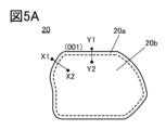
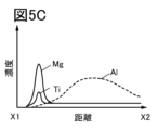
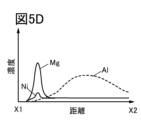
- FIGS. 5B to 5E are diagrams illustrating the distribution of added elements.
- FIG. 6 is an example of a TEM image in which the crystal orientations are roughly consistent.
- Fig. 7A is an example of an STEM image in which the crystal orientations are roughly consistent,
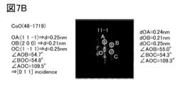
- Fig. 7B is an FFT pattern of a region of the rock-salt crystal RS, and
- FIG. 7C is an FFT pattern of a region of the layered rock-salt crystal LRS.
- FIG. 8 is a diagram illustrating the change in the crystal structure of the positive electrode active material.
- FIG. 9 is a diagram illustrating the change in the crystal structure of a conventional positive electrode active material.
- FIG. 10 is an XRD (X-ray diffraction) pattern.
- FIG. 11 is the XRD pattern.
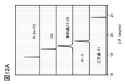
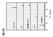
- 12A and 12B are XRD patterns.
- FIG. 13 is a cross-sectional view of a positive electrode active material particle.
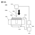
- 14A and 14B are diagrams illustrating the nail penetration test.
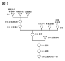
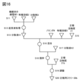
- FIG. 15 is a diagram illustrating a method for producing a positive electrode.
- FIG. 16 is a diagram illustrating a method for producing a positive electrode.
- FIG. 16 is a diagram illustrating a method for producing a positive electrode.
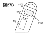
- FIGS. 27A to 27C are diagrams illustrating a two-wheeled vehicle etc. according to one embodiment of the present invention.
- 28A to 28D illustrate electronic devices or the like according to one embodiment of the present invention.
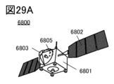
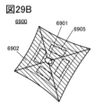
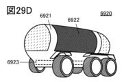
- 29A to 29D are diagrams showing an example of space equipment.
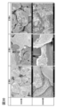
- FIG. 30 is an SEM image of an example.
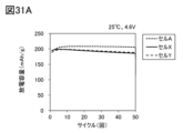
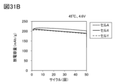
- 31A and 31B show the results of a cycle test of the embodiment.
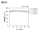
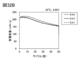
- 32A and 32B show the results of a cycle test of the embodiment.
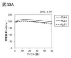
- 33A and 33B show the results of a cycle test of the embodiment.
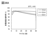
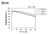
- 34A and 34B show cycle test results for the embodiment.
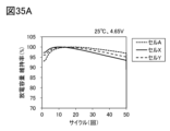
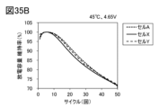
- 35A and 35B show cycle test results for the embodiment.
- 36A and 36B show the cycle test results of the embodiment.
- 37A and 37B show the results of measuring the discharge capacity at different rates in the example.
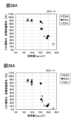
- 38A and 38B show the results of measuring the discharge capacity at different rates in the example.
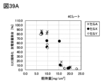
- 39A and 39B show the results of measuring the discharge capacity at different rates in the example.
- a lithium ion secondary battery is sometimes called a lithium ion battery, and refers to a battery that uses lithium ions as carrier ions, but the carrier ions of the present invention are not limited to lithium ions.
- the carrier ions of the present invention are not limited to lithium ions.
- alkali metal ions or alkaline earth metal ions can be used as carrier ions of the present invention, and specifically, sodium ions, etc. can be applied.
- the present invention can be understood by reading lithium ions as sodium ions, etc.
- it may be referred to as a secondary battery.
- an electrode with a high reaction potential is called a positive electrode
- an electrode with a low reaction potential is called a negative electrode. Therefore, whether during charging or discharging, the positive electrode is called a “positive electrode” or “+ electrode (plus electrode),” and the negative electrode is called a “negative electrode” or “- electrode (minus electrode).” Note that in secondary batteries, oxidation reactions and reduction reactions alternate during charging and discharging.
- a full cell refers to a battery cell assembled with different electrodes in place, such as a positive/negative unit cell.
- a half cell refers to a battery cell assembled with lithium metal as the negative electrode (counter electrode).
- the term "slurry” refers to a material liquid used to form an active material layer on a current collector, containing an active material, a binder, and a solvent, and preferably further mixed with a conductive material.
- the slurry is sometimes called an electrode slurry or an active material slurry
- the slurry for forming a positive electrode active material layer is sometimes called a positive electrode slurry
- the slurry for forming a negative electrode active material layer is sometimes called a negative electrode slurry.
- the amount of support is the weight of active material per unit area.
- the amount of support is considered per side.
- the median diameter (D50) is one of the powder characteristics, and is the particle diameter when the cumulative amount in the cumulative curve of the particle size distribution measurement results is 50%.
- a high charging voltage is, for example, a charging voltage of 4.6 V or higher, preferably 4.65 V or higher, and more preferably 4.7 V or higher.
- the C rate is the ratio of the charge/discharge current value to the secondary battery capacity, and serves as a standard for judging the charge/discharge characteristics of a secondary battery. In other words, the characteristics of secondary batteries with different capacities can be compared under the same conditions by using the C rate.
- 1C represents the current value that changes from a fully charged state to a discharged state in one hour. Unless otherwise specified, in this specification, the current value equivalent to 1C is 200 mA/g per weight of the positive electrode active material.
- the space group is expressed using short notation of the international notation (or Hermann-Mauguin notation).
- the crystal plane and crystal direction are expressed using Miller indices.
- the space group, crystal plane, and crystal direction are expressed by adding a superscript bar to the numbers, but in this specification, due to format restrictions, instead of adding a bar above the numbers, a - (minus sign) may be added before the numbers.
- Individual directions indicating directions within a crystal are expressed with [ ]
- collective directions indicating all equivalent directions are expressed with ⁇ >
- individual faces indicating crystal faces are expressed with ( )
- collective faces with equivalent symmetry are expressed with ⁇ ⁇ .
- trigonal crystals represented by the space group R-3m are generally sometimes expressed as a composite hexagonal lattice of hexagonal crystals for ease of understanding the structure.
- hkl not only (hkl) but also (hkil) may be used as Miller indices.
- i is -(h+k).
- crystal planes and the like are represented as a compound hexagonal lattice unless otherwise specified.
- the space group of a crystal structure is identified by XRD, electron diffraction, neutron diffraction, etc. Therefore, in this specification, etc., belonging to a certain space group, belonging to a certain space group, or being a certain space group can be rephrased as being identified with a certain space group.
- the arrangement of anions is roughly close to cubic close-packed, it can be considered as cubic close-packed.
- the arrangement of anions in cubic close-packed refers to a state in which the second layer of anions is arranged above the gaps of the anions packed in the first layer, and the third layer of anions is arranged directly above the gaps of the second layer of anions, but not directly above the anions in the first layer. Therefore, the anions do not have to be strictly cubic lattices. In addition, since real crystals always have defects, the analysis results do not necessarily have to be theoretical.
- a spot may appear at a position slightly different from the theoretical position. For example, if the deviation from the theoretical position and the orientation is 5 degrees or less, or 2.5 degrees or less, it can be said that the structure has a cubic close-packed structure.
- the shape of the active material or conductive material may be described as particulate, and particulate shapes include spherical shapes (cross-sectional shapes that are circular).
- the shape of the active material or conductive material is not limited to spherical, and may include cross-sectional shapes that are elliptical, rectangular, trapezoidal, triangular, square with rounded corners, asymmetrical, etc., and further, individual particles may be irregular.
- the smooth surface of an active material means that the surface roughness of a cross section of the active material is at least 10 nm or less when the surface unevenness information is quantified from measurement data.
- a cross section is, for example, a cross section obtained when observing with a STEM (Scanning Transmission Electron Microscope) image.
- aging treatment includes a process that involves one or more cycles of charging and discharging at a temperature equal to or higher than room temperature (25°C), or a process that involves holding the secondary battery at a temperature close to the upper limit of the operating temperature range (typically 60°C) for a long period of time.
- the aging treatment may further include a process of releasing gas generated in the area covered by the exterior body. The aging treatment makes it possible to detect initial defects in the secondary battery. Furthermore, when one or more cycles of charging and discharging are performed, a stable coating can be formed on the negative electrode active material.
- the materials (positive electrode active material, negative electrode active material, electrolyte, separator, etc.) of the secondary battery are described in the state before degradation.
- a decrease in discharge capacity due to aging treatment during the secondary battery manufacturing stage is not called degradation.
- a lithium-ion secondary battery that has a discharge capacity of 97% or more of its rated capacity can be said to be in a state before degradation.
- the rated capacity complies with JIS C 8711:2019.
- other lithium-ion secondary batteries they are not limited to the above JIS standards, but also comply with various JIS and IEC standards for electric vehicle propulsion, industrial use, etc.
- the state of the materials in a secondary battery before degradation is referred to as an initial product or initial state
- the state after degradation (the state when the secondary battery has a discharge capacity of less than 97% of the rated capacity) may be referred to as a product in use or in use state, or a used product or used state.
- the theoretical capacity of a positive electrode active material refers to the amount of electricity when all of the lithium ions that can be inserted and removed from the positive electrode active material are removed.
- the theoretical capacity of LiCoO2 is 274 mAh/g per active material weight
- the theoretical capacity of LiNiO2 is 275 mAh/g per active material weight
- the theoretical capacity of LiMn2O4 is 148 mAh/g per active material weight.
- the amount of lithium ions remaining in the positive electrode active material that can be inserted and removed is indicated by x in the composition formula, for example, x in Li x CoO 2.
- x (theoretical capacity - charging capacity) / theoretical capacity.
- LiCoO 2 LiCoO 2
- x 0.2.
- x in Li x CoO 2 is small means 0.1 ⁇ x ⁇ 0.24.
- the completion of discharge here refers to, for example, a state in which the voltage reaches 3.0 V or 2.5 V at a current of 100 mA/g or less.
- the charge capacity and/or discharge capacity used to calculate x in Li x CoO 2 is measured under conditions that are free of or have little influence from short circuit and/or decomposition of the electrolyte, etc. For example, data from a secondary battery that has experienced a sudden change in capacity that is considered to be due to a short circuit should not be used to calculate x.
- the distribution of a certain element may refer to a region in which the element is continuously detected in a non-noise range. Detecting a continuous distribution of a certain element in a non-noise range includes detecting a continuous distribution of a certain element in a non-noise range when an analysis is performed multiple times.
- ignition in a nail penetration test means that a flame is observed outside the exterior body within one minute of the nail being inserted, or that thermal runaway of the secondary battery has occurred.
- thermal decomposition products of the positive electrode and/or negative electrode include aluminum oxide, which is formed by the oxidation of aluminum in the positive electrode current collector, and copper oxide, which is formed by the oxidation of copper in the negative electrode current collector.
- the (001) plane and the (003) plane may be collectively referred to as the (00l) plane.
- the (00l) plane may be referred to as the C plane, the basal plane, or the like.
- lithium ions have a two-dimensional diffusion path. In other words, it can be said that the diffusion path of lithium ions exists along the surface.
- a surface on which the lithium diffusion path is exposed that is, a surface other than the surface on which lithium ions are inserted and removed (specifically, the (00l) plane), may be referred to as an edge surface.
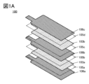
- Figure 1A shows a laminated secondary battery 100, with each component shown separated for ease of viewing.
- the secondary battery 100 has multiple positive electrodes.
- the multiple positive electrodes shown in the figure are a first positive electrode 103a and a second positive electrode 103b.
- the first positive electrode 103a and the second positive electrode 103b are collectively referred to as the positive electrode 103.
- the secondary battery 100 has multiple negative electrodes. As the multiple negative electrodes, a first negative electrode 106a, a second negative electrode 106b, and a third negative electrode 106c are illustrated. However, the number of negative electrodes in the secondary battery 100 is not limited in any way, and may be a single electrode.
- the first negative electrode 106a, the second negative electrode 106b, and the third negative electrode 106c are collectively referred to as the negative electrode 106.
- the secondary battery 100 has a separator between the negative electrode and the positive electrode.
- the separator is shown by a dotted line in FIG. 1A.
- the separators are a first separator 105a, a second separator 105b, a third separator 105c, and a fourth separator 105d.
- the number of separators in the secondary battery 100 is not limited, and may be a single separator.
- the separator may be independent as shown in the figure, but a continuous separator can also be used. By folding the continuous separator, the separator can be positioned at a position corresponding to the first separator 105a to the fourth separator 105d.
- the first separator 105a, the second separator 105b, the third separator 105c, and the fourth separator 105d are collectively referred to as separator 105.
- Figure 1B shows the state in which the components of the secondary battery 100 are overlapped.
- the first positive electrode 103a and the second positive electrode 103b both have a positive electrode current collector, and each positive electrode current collector has a protrusion 103t.
- the protrusions 103t of each positive electrode current collector overlap and form an assembly.
- the assembly of protrusions 103t is called a positive electrode tab.
- the first negative electrode 106a, the second negative electrode 106b, and the third negative electrode 106c each have a negative electrode current collector, and each negative electrode current collector has a protrusion 106t.
- the protrusions 106t of each negative electrode current collector overlap and form an assembly.
- the assembly of protrusions 106t is called a negative electrode tab.
- multiple positive electrodes, multiple negative electrodes, and multiple separators are collectively referred to as a stacked electrode.
- the positive electrode tab (projection 103t) is joined to the positive electrode lead 107a at the joint 109a.
- the negative electrode tab is joined to the negative electrode lead 107b at the joint 109b.
- Ultrasonic bonding can be used for the bonding. As a result of the bonding, they are electrically connected to each other.
- the positive electrode lead 107a can be made of a material selected from aluminum, nickel, titanium, or an alloy thereof.
- the negative electrode lead 107b can be made of a material selected from nickel, copper, titanium, or an alloy thereof.
- the secondary battery 100 has an exterior body (not shown), and the laminated electrode shown in FIG. 1B is housed in the exterior body. From the viewpoint of weight reduction, it is preferable to use a film for the exterior body.
- a secondary battery using a film for the exterior body is called a laminated type secondary battery.
- the secondary battery that is one embodiment of the present invention is a coin-shaped laminated type secondary battery.
- a can case may be applied to the exterior body, and a circular can case can be used, which is called a coin-type secondary battery (coin cell).
- the secondary battery of one embodiment of the present invention can be a coin-type secondary battery (coin cell).
- the secondary battery of one embodiment of the present invention is not limited in any way by its external appearance.
- the secondary battery of one embodiment of the present invention is not limited in any way by the material of the exterior body.
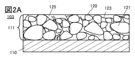
- ⁇ Positive Electrode Configuration Example 1> 2A shows a cross-sectional view of the positive electrode 103.
- the positive electrode 103 has a positive electrode current collector 110 and a positive electrode active material layer 111.
- the positive electrode active material layer 111 is a layer having first positive electrode active material particles 120 and second positive electrode active material particles 121, etc., and has a region in contact with the positive electrode current collector 110.
- the positive electrode active material layer is preferably formed on both sides of the positive electrode current collector. This is called a double-sided coated structure.
- the positive electrode active material layer may be formed on only one side of the positive electrode current collector. This is called a single-sided coated structure.
- the positive electrode active material layer 111 shown in FIG. 2A further includes a first conductive material 123 and a void 125.
- the void 125 in the positive electrode 103 may be impregnated with an electrolyte.
- the electrolyte may be in contact with the first positive electrode active material particles 120 and the second positive electrode active material particles 121, or may be impregnated into a portion of the first positive electrode active material particles 120 or a portion of the second positive electrode active material particles 121.
- the electrolyte may be in contact with the first conductive material 123, or may be impregnated into a portion of the first conductive material 123.
- washing may be performed using an organic solvent.
- the first conductive material 123 may be typically fibrous, and in the case of fibrous form, the first conductive material 123 has a long axis.
- the surface of the positive electrode active material layer 111 is illustrated as being uniform, but the surface has an uneven shape that follows the shapes of the first positive electrode active material particles 120 and the second positive electrode active material particles 121.
- the interface between the positive electrode collector 110 and the positive electrode active material layer 111 is illustrated as being uniform, but the surface of the positive electrode collector 110 may have a recess in the area where the first positive electrode active material particles 120 and the second positive electrode active material particles 121 overlap each other.
- the positive electrode active material layer 111 coated on the positive electrode collector 110 may undergo a press processing process, and when this process is performed, the first positive electrode active material particles 120 and the second positive electrode active material particles 121 are pressed into the surface of the positive electrode collector 110, forming the recess.
- the first positive electrode active material particles 120 have a particle diameter different from that of the second positive electrode active material particles 121. Specifically, it is preferable that the first positive electrode active material particles 120 have a particle diameter of less than 10 ⁇ m, and the second positive electrode active material particles 121 have a particle diameter of 10 ⁇ m or more and 50 ⁇ m or less. More preferably, the particle diameter of the first positive electrode active material particles 120 is 1/12 times or more and 1/8 times or less of the particle diameter of the second positive electrode active material particles 121. As long as the above-mentioned particle diameter is satisfied, the composition of the first positive electrode active material particles 120 may be the same as the composition of the second positive electrode active material particles 121. Furthermore, as long as the above-mentioned particle diameter is satisfied, the composition of the first positive electrode active material particles 120 may be different from the composition of the second positive electrode active material particles 121.
- the particle diameter of each particle can be calculated from a cross-sectional SEM image including the first positive electrode active material particles 120 and the second positive electrode active material particles 121 by the following method.
- cut out the analysis area from the acquired cross-sectional SEM image For example, a range of 50 ⁇ m or more ⁇ 100 ⁇ m or more can be cut out as a range with a sufficient area for image analysis, but this is not limited to this.
- the cross-sectional SEM image may be cut out using the functions of image processing software.
- ImageJ may be used as the image processing software, and the image may be cut out using its crop function.
- the first image cut out is binarized using image processing software and particle analysis is performed.
- Image processing software that can be used is, for example, ImageJ.
- the binarization process is explained below.
- a first image shown in a 256-value grayscale is used as a frequency graph excluding black (value 0) and white (value 255), and the low value side (HWHM_L) and high value side (HWHM_H) are obtained as the half-width at half maximum (HWHM) of the maximum peak in the frequency graph.
- HWHM_L low value side
- HWHM_H high value side
- a minimum value a of the range that is twice the width of HWHM_L on the low value side from the value that is the peak top (maximum frequency) of the maximum peak and a maximum value b of the range that is twice the width of HWHM_H on the high value side are determined.
- binarization is performed so that the range of values less than a is white, the range of values between a and b is black, and the range of values greater than b is white.
- binarization is performed as Threshold (AB) using ImageJ's Threshold function.
- the particle diameter of each particle can be obtained from the cross-sectional SEM image. This is called particle diameter analysis using a cross-sectional SEM image of the positive electrode.
- the particle size distribution of each particle can also be obtained from the particle diameter. This is called particle size distribution analysis using a cross-sectional SEM image of the positive electrode.
- the electrode density in the positive electrode 103 can be increased.
- the electrode density here is the weight of the electrode layer including the first positive electrode active material particles 120 and the second positive electrode active material particles per unit volume of the positive electrode active material layer 111.
- the electrode layer includes a conductive material.
- the electrode layer may also include a binder.
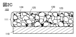
- the positive electrode active material layer 111 has first positive electrode active material particles 120, second positive electrode active material particles 121, a first conductive material 123, a second conductive material 124, and voids 125.
- the first conductive material 123 is fibrous and the second conductive material 124 is particulate.
- the first conductive material 123 and the second conductive material 124 may be made of the same material.
- the first conductive material 123 and the second conductive material 124 may be made of different materials.
- the second conductive material 124 is preferably present in an aggregated state near the first positive electrode active material particles 120.
- the second conductive material 124 is preferably present in an aggregated state near the second positive electrode active material particles 121.
- the second conductive material 124 is preferably present in an aggregated state between the first positive electrode active material particles 120 and the second positive electrode active material particles 121.
- the above-mentioned aggregated second conductive material 124 can also be said to be located in the voids 125. In other words, the aggregated second conductive material 124 located in the voids 125 may hold an electrolyte.
- the weight of the first conductive material 123 may be different from the weight of the second conductive material 124.
- the weight may be the amount charged at the stage of preparing the positive electrode 103, or may be the weight that can be analyzed from the positive electrode 103.
- the weight of the second conductive material 124 is equal to or greater than the weight of the first conductive material 123, typically, the weight of the second conductive material 124 is two to five times, preferably two to three times, the weight of the first conductive material 123.
- This configuration allows the conductivity of the positive electrode 103 to be appropriate. Furthermore, this configuration allows the conductivity of the positive electrode 103 to be higher than when one type of conductive material is used. As a result, the secondary battery 100 can exhibit good rate characteristics.
- the electrode density at the positive electrode 103 can be increased.
- the positive electrode active material layer 111 has first positive electrode active material particles 120, a first conductive material 123, a second conductive material 124, and voids 125. In other words, the positive electrode active material layer 111 does not necessarily have to have the second positive electrode active material particles 121.
- the positive electrode active material layer 111 does not necessarily have to include the second conductive material 124 in addition to the second positive electrode active material particles 121 .
- ⁇ Positive Electrode Configuration Example 5> 2D shows a cross-sectional view of the positive electrode 103.
- the positive electrode active material layer 111 has second positive electrode active material particles 121, a first conductive material 123, a second conductive material 124, and voids 125. In other words, the positive electrode active material layer 111 does not necessarily have to have the first positive electrode active material particles 120.
- the positive electrode active material layer 111 does not necessarily have to include the second conductive material 124 in addition to the first positive electrode active material particles 120 .
- a first positive electrode active material particle 120 is used as the positive electrode active material particle, and a first conductive material 123 is used as the conductive material.
- the first positive electrode active material particle 120 may be replaced with a second positive electrode active material particle 121 to understand the characteristics of the positive electrode active material particle and the conductive material. In other words, this characteristic can be applied to the relationship between the positive electrode active material particle and the fibrous conductive material in the above-described positive electrode configuration examples 1 to 6.
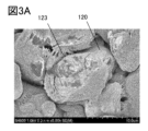
- Figure 3A is an example of a surface SEM image of a positive electrode 103 including a first positive electrode active material particle 120 and a first conductive material 123
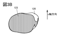
- Figure 3B is a schematic diagram of the first positive electrode active material particle 120 and the first conductive material 123 according to Figure 3A.
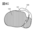
- the first positive electrode active material particle 120 is generally entirely wrapped by the first conductive material 123.
- the generally entirely wrapped particle includes a configuration in which 60% or more, preferably 70% or more, more preferably 80% or more, and even more preferably 90% or more of the first positive electrode active material particle 120 overlaps with the first conductive material 123 in a top view of the positive electrode, typically a surface SEM image.
- the generally entirely wrapped particle includes a configuration in which 60% or more, preferably 70% or more, more preferably 80% or more, and even more preferably 90% or more of the first positive electrode active material particle 120 overlaps with the first conductive material 123 in a cross-sectional view of the positive electrode, typically a cross-sectional SEM image or a cross-sectional TEM image. Wrapping in a cross-sectional view may be equivalent to the first conductive material 123 being positioned along the first positive electrode active material particle 120.
- the word “wrap” can also be expressed as “cover,” “shroud,” “stick,” “adhere,” “stick around,” “bind,” “surround and bind,” or “wrap around,” etc.
- the first conductive material 123 may have a plurality of fibrous conductive materials.
- the first conductive material 123 may have an aggregate of fibrous conductive materials.
- the aggregate of conductive materials can wrap substantially the entire first positive electrode active material particle 120.
- a plurality of fibrous conductive materials may be entangled with each other.
- aggregates of conductive materials may be entangled with each other.
- the surface of the fibrous conductive material may be uneven (scratched). In the entangled state, the length in the long axis direction is longer than the long axis of one fibrous conductive material. Therefore, by using the entangled state, substantially the entire first positive electrode active material particle 120 may be wrapped in an aggregate of fibrous conductive materials.
- wrap refers to the first positive electrode active material particle 120 and the first conductive material 123 being physically in close contact with each other.
- the terms are not limited to the first positive electrode active material particle 120 and the first conductive material 123 being physically in close contact with each other, and may include cases where a covalent bond is formed, where the first conductive material 123 is bonded by van der Waals forces, and where the first conductive material 123 is embedded in the surface irregularities of the first positive electrode active material particle 120.
- the states of wrapping, covering, covering, sticking, attaching, clinging, binding, surrounding and binding, or wrapping can be confirmed in a surface SEM image of the positive electrode or a cross-sectional SEM image of the positive electrode, and it is sufficient that at least the first positive electrode active material particle 120 and the first conductive material 123 are in contact with each other in the surface SEM image of the positive electrode or the cross-sectional SEM image of the positive electrode.
- a binder may be located at the interface or part of the interface between the first positive electrode active material particles 120 and the first conductive material 123. This is because the binder does not impede the crack suppression effect described below.
- a crack may be referred to as a region where the crystal plane is displaced or a region where the crystal plane is broken, and often occurs along the (00l) plane. It is preferable that no cracks are observed in the first positive electrode active material particles 120.
- the first positive electrode active material particles 120 and the first conductive material 123 as shown in Figures 3A and 3B can be obtained by preparing a positive electrode slurry using a dispersion liquid in which the first conductive material 123 is well dispersed.
- the first positive electrode active material particles 120 may be configured to be wrapped in the first conductive material 123.
- the conductivity of the positive electrode 103 can be increased. As a result, the secondary battery 100 can exhibit good rate characteristics.
- the safety of the secondary battery 100 is improved.
- the first conductive material 123 can suppress the occurrence of cracks in the first positive electrode active material particles 120.
- cleavage, cracking, and shifting may occur in the first positive electrode active material particles 120. These are collectively referred to as cracks, etc., and the occurrence of cracks, etc. is suppressed by wrapping the first positive electrode active material particles 120 in the first conductive material 123 (crack suppression effect).
- the first positive electrode active material particle 120 has lithium cobalt oxide.
- Lithium cobalt oxide having a basal surface and an edge surface is prone to cracks and the like from the edge surface. Therefore, the first conductive material 123 is configured to wrap the edge surface of the first positive electrode active material particle 120, in other words, the first conductive material 123 wraps the edge surface of the first positive electrode active material particle 120 so that the cracks do not progress, thereby improving the safety of the secondary battery.
- Wrapping the edge surface includes a configuration in which 60% or more, preferably 70% or more, more preferably 80% or more, and even more preferably 90% or more of the edge surface of the first positive electrode active material particle 120 overlaps with the first conductive material 123 in a top view of a positive electrode having an edge surface, typically in a surface SEM image. Additionally, wrapping the edge surface includes a configuration in which 60% or more, preferably 70% or more, more preferably 80% or more, and even more preferably 90% or more of the edge surface of the first positive electrode active material particle 120 overlaps with the first conductive material 123 in a cross-sectional view of the positive electrode having the edge surface, typically in a cross-sectional SEM image or cross-sectional TEM image.
- the first conductive material 123 may have a state in which multiple conductive materials are entangled with each other. By having the first conductive material 123 wrapping the edge surface in the entangled state, the progression of cracks in the first positive electrode active material particle 120 can be further suppressed, thereby improving safety.
- the first conductive material 123 can encase the second positive electrode active material particles 121 instead of the first positive electrode active material particles 120.
- the second positive electrode active material particles 121 may be encased in the first conductive material 123.
- the conductivity of the positive electrode 103 can be increased. As a result, the secondary battery 100 can exhibit good rate characteristics.
- the safety of the secondary battery 100 is improved.
- One configuration that improves safety is a state in which the long axis of the first conductive material 123 is wrapped along the c-axis direction of the second positive electrode active material particles 121. This configuration suppresses the occurrence of cracks, etc. in the second positive electrode active material particles 121. Furthermore, the occurrence of cracks, etc. is suppressed by wrapping the second positive electrode active material particles 121 with the first conductive material 123 via the binder.
- the first conductive material 123 can actively surround the first positive electrode active material particles 120 with respect to the first positive electrode active material particles 120 and the second positive electrode active material particles 121.
- a positive electrode slurry in which the first positive electrode active material particles 120 are mixed with a dispersion liquid in which the first conductive material 123 is well dispersed is prepared, and the second positive electrode active material particles 121 are subsequently mixed into the positive electrode slurry, whereby a configuration in which the first conductive material 123 actively surrounds the first positive electrode active material particles 120 may be obtained.
- the configuration in which the first conductive material 123 actively surrounds the first positive electrode active material particles 120 includes a configuration in which the area of the first conductive material 123 overlapping the first positive electrode active material particles 120 is larger than that of the second positive electrode active material particles 121 in a surface SEM image of the positive electrode or a cross-sectional SEM image of the positive electrode.
- the conductivity of the positive electrode 103 can be increased.
- the secondary battery 100 can exhibit good rate characteristics.
- the first positive electrode active material particles 120 are actively wrapped with the first conductive material 123, the occurrence of cracks and the like is suppressed.
- the first positive electrode active material particles 120 are actively wrapped with the first conductive material 123 via the binder, the occurrence of cracks and the like is suppressed. In other words, the safety of the secondary battery 100 is improved.
- the first conductive material 123 can actively surround the second positive electrode active material particles 121 with respect to the first positive electrode active material particles 120 and the second positive electrode active material particles 121.
- a positive electrode slurry in which the second positive electrode active material particles 121 are mixed with a dispersion liquid in which the first conductive material 123 is well dispersed is prepared, and the first positive electrode active material particles 120 are later mixed into the positive electrode slurry, whereby a configuration in which the first conductive material 123 actively surrounds the second positive electrode active material particles 121 may be obtained.
- the configuration in which the first conductive material 123 actively surrounds the second positive electrode active material particles 121 includes a configuration in which the area of the first conductive material 123 overlapping the second positive electrode active material particles 121 is larger than that of the first positive electrode active material particles 120 in a surface SEM image of the positive electrode or a cross-sectional SEM image of the positive electrode.
- the conductivity of the positive electrode 103 can be increased.
- the secondary battery 100 can exhibit good rate characteristics.
- the second positive electrode active material particles 121 are actively wrapped with the first conductive material 123, the occurrence of cracks and the like is suppressed.
- the second positive electrode active material particles 121 are actively wrapped with the first conductive material 123 via the binder, the occurrence of cracks and the like is suppressed. In other words, the safety of the secondary battery 100 is improved.
- the positive electrode active material used in the first positive electrode active material particle 120 includes lithium composite oxides having an olivine crystal structure, a layered rock salt crystal structure, or a spinel crystal structure.
- the positive electrode active material is not particularly limited as long as it is a lithium composite oxide, but the substitute target can be one or more of lithium cobalt oxide (LiCoO 2 , but the composition is not limited, also called LCO), lithium iron phosphate (LiFePO 4 , but the composition is not limited, also called LFP), lithium nickel oxide (LiNiO 2 ), lithium manganese oxide (LiMn 2 O 4 , but the composition is not limited), lithium manganese phosphate (LiMnPO 4 , but the composition is not limited), and lithium manganese iron phosphate (LiFe a Mn b PO 4 : a + b is 1 or less, 0 ⁇ a ⁇ 1, 0 ⁇ b ⁇ 1).
- lithium iron phosphate is used, it
- the positive electrode active material used for the second positive electrode active material particles 121 includes lithium composite oxides having an olivine type crystal structure, a layered rock salt type crystal structure, or a spinel type crystal structure.
- the positive electrode active material is not particularly limited as long as it is a lithium composite oxide, but the substitute target may be one or more of lithium cobalt oxide, lithium iron phosphate, lithium nickel oxide, lithium manganese oxide (LiMn 2 O 4 ), lithium manganese phosphate, and lithium manganese iron phosphate. When lithium iron phosphate is used, it is preferable to use one coated with carbon.
- the first conductive material 123 and the second conductive material 124 may each be made of a metal material or a carbon material. Carbon fiber or the like may be used as the first conductive material 123. Carbon fiber can be considered to be a fibrous conductive material. Instead of carbon fiber, graphene or a graphene compound may be used as the first conductive material 123. Graphene or a graphene compound can be considered to be a sheet-like conductive material. Furthermore, graphene or a graphene compound may be added to the positive electrode 103 as a third conductive material.
- graphene refers to a material that contains carbon, has a shape such as a plate or sheet, and has a two-dimensional structure formed by six-membered carbon rings.
- graphene includes multi-layer graphene. Graphene exhibits excellent electrical properties, such as high conductivity, and is therefore suitable as a conductive material.
- graphene compounds include graphene oxide, multi-layer graphene oxide, reduced graphene oxide, reduced multi-layer graphene oxide, and the like.
- the graphene compound may have a functional group, and examples of the functional group include an epoxy group, a carboxy group, and a hydroxy group.
- Graphene compounds are suitable as conductive materials because they exhibit excellent electrical properties, such as high flexibility and high conductivity.
- particulate conductive materials such as carbon black, Ketjen Black (registered trademark), and acetylene black (hereinafter sometimes referred to as AB) can be used. Such particulate conductive materials may be aggregated in the positive electrode 103. The aggregated state is sometimes called an aggregate.
- Carbon fibers that function as conductive materials include CNT, VGCF (registered trademark), or carbon fiber.
- CNTs have a layer of carbon atoms, and when the number of layers is one, they are called single-wall nanotubes, and when the number of layers is multiple, they are called multi-wall nanotubes, and multi-wall nanotubes include double-wall nanotubes with two layers.
- Carbon fibers can form aggregates.
- carbon fibers can form entangled shapes because of their large long axis or fiber length, and this state is called an aggregate.
- An entangled shape includes a state in which one carbon fiber is entangled, or a state in which multiple carbon fibers are entangled. To form an entangled shape, the carbon fiber may have unevenness (scratches) on the surface.
- the specific surface area of VGCF is 100 m 2 /g or more, preferably 60 m 2 /g or more, and more preferably 20 m 2 /g or more.
- the specific surface area of CNT is 500 m 2 /g or more, preferably 650 m 2 /g or more, and more preferably 800 m 2 /g or more.
- the specific surface area is a value measured by the Brunauer Emmett Teller method (BET method).
- the long axis or fiber length of VGCF (registered trademark) is preferably 1 ⁇ m or more and 100 ⁇ m or less, more preferably 2 ⁇ m or more and 20 ⁇ m or less.
- the long axis or fiber length of CNT is preferably 100 ⁇ m or more and 600 ⁇ m or less, more preferably 200 ⁇ m or more and 500 ⁇ m or less.
- the carbon fiber will wrap multiple positive electrode active materials, so in one aspect of the present invention, it is not limited to the above numerical values.
- the carbon fibers are entangled, the long axis when entangled becomes important as a conductive material.
- the entangled carbon fibers can wrap multiple positive electrode active materials.
- the average diameter of the carbon fiber is preferably 1 nm or more and 180 nm or less, and more preferably 2 nm or more and 150 nm or less.
- VGCF registered trademark
- VGCF can have an average diameter of 100 nm or more and 180 nm or less, and preferably 130 nm or more and 160 nm or less, and can be said to have a large average diameter.
- VGCF (registered trademark) with a large average diameter exhibits high dispersibility.
- CNT can have an average diameter of 1 nm or more and 100 nm or less, and more preferably 1 nm or more and 50 nm or less, and more preferably 3 nm or more and 5 nm or less, and can be said to have a small average diameter.
- Carbon fibers are preferred because they easily aggregate and satisfy the above-mentioned length and average diameter.
- the aggregated carbon fibers can suppress the occurrence of cracks in the positive electrode active material while exhibiting the function of a conductive path for the positive electrode active material, and can suppress the deterioration of multiple positive electrode active materials due to charge/discharge cycles.
- carbon fiber or carbon fiber aggregates are preferred as conductive materials because they provide a long-distance conductive path. For example, they can ensure a conductive path between the positive electrode collector 110 and the first positive electrode active material particles 120 located far away, enabling rapid charging and discharging. Carbon fiber or carbon fiber aggregates that can ensure a conductive path can provide good charge and discharge cycle characteristics even at a low content. Therefore, they are preferred because they can increase the content of positive electrode active material particles in the positive electrode 103.
- the total content of the first conductive material 123 and the second conductive material 124 relative to the total amount of the positive electrode active material layer 111 is preferably 0.1 wt% or more and 10 wt% or less, and more preferably 1 wt% or more and 5 wt% or less. Since the shapes of the first conductive material 123 and the second conductive material 124 are different from each other, it is preferable that the proportion of the positive electrode active material in the positive electrode active material layer 111 can be further increased. Furthermore, the proportion of the first conductive material 123 and the second conductive material 124 is not limited, but it is preferable that the proportion of the first conductive material 123 is equal to or more than the proportion of the second conductive material 124.
- the carbon fibers or carbon fiber aggregates can also wrap multiple positive electrode active materials together, as can be seen from their appearance.
- the carbon fibers or carbon fiber aggregates can also be bound so as to surround the positive electrode active material, as can be seen from their appearance. This configuration improves the safety of the secondary battery 100.
- the above-mentioned carbon fibers may be dispersed in water or an organic solvent using a dispersant. Even when carbon fibers are mixed with particulate conductive material, they can be dispersed in water or an organic solvent using the above-mentioned dispersant.
- organic solvents include N-methyl-2-pyrrolidone (NMP).
- NMP N-methyl-2-pyrrolidone
- PVP polyvinylpyrrolidone
- PVP polyvinylpyrrolidone
- the positive electrode active material layer 111 may further include a binder.
- the binder can strengthen the positive electrode 103.
- the positive electrode 103 can eliminate the need for a binder.
- the binder can be eliminated. Eliminating the need for a binder is preferable because it can further increase the proportion of the positive electrode active material in the positive electrode active material layer 111.
- the binder has the function of binding various components such as positive electrode active materials together, conductive materials together, and positive electrode active materials and positive electrode current collectors. Furthermore, it is preferable that the binder exhibits thermal stability and is electrochemically stable at the positive electrode potential.
- rubber materials such as styrene-butadiene rubber (SBR), styrene-isoprene-styrene rubber, acrylonitrile-butadiene rubber, butadiene rubber, and ethylene-propylene-diene copolymer as the binder.
- SBR styrene-butadiene rubber
- styrene-isoprene-styrene rubber acrylonitrile-butadiene rubber, butadiene rubber, and ethylene-propylene-diene copolymer
- Fluorocarbon rubber can also be used as the binder.
- a water-soluble polymer as the binder.
- polysaccharides can be used as the water-soluble polymer.
- cellulose derivatives such as carboxymethyl cellulose (CMC), methyl cellulose, ethyl cellulose, hydroxypropyl cellulose, diacetyl cellulose, and regenerated cellulose, or starch can be used as the polysaccharide.
- CMC carboxymethyl cellulose
- methyl cellulose methyl cellulose
- ethyl cellulose methyl cellulose
- hydroxypropyl cellulose diacetyl cellulose
- regenerated cellulose or starch
- a polymer material such as polystyrene, polymethyl acrylate, polymethyl methacrylate (polymethyl methacrylate, PMMA), sodium polyacrylate, polyvinyl alcohol (PVA), polyethylene oxide (PEO), polypropylene oxide, polyimide, polyvinyl chloride, polytetrafluoroethylene, polyethylene, polypropylene, polyisobutylene, polyethylene terephthalate, nylon, polyvinylidene fluoride (PVDF), polyacrylonitrile (PAN), ethylene propylene diene polymer, polyvinyl acetate, or nitrocellulose.
- Polymer materials are preferred because they are flexible and therefore easy to increase electrode density. PVDF has CH bonds and CF bonds, but does not have polarity as a whole, so it is preferred because it is easy to disperse appropriately within the positive electrode.
- the binder may be a combination of two or more of the above. Also, since the binder is not a material that directly contributes to the battery characteristics, the binder may be unnecessary.
- the binder may be used in combination with a material having a particularly excellent viscosity adjusting effect (the material may be called a thickener) and other materials.
- a material having a particularly excellent viscosity adjusting effect the material may be called a thickener
- a rubber material or the like has excellent adhesive strength and elasticity, but it may be difficult to adjust the viscosity when mixed with a solvent. In such a case, it is preferable to mix a rubber material with a material having a particularly excellent viscosity adjusting effect.
- a water-soluble polymer may be used as a material having a particularly excellent viscosity adjusting effect.
- the above-mentioned polysaccharides such as carboxymethyl cellulose (CMC), methyl cellulose, ethyl cellulose, hydroxypropyl cellulose, and diacetyl cellulose, cellulose derivatives such as regenerated cellulose, or starch may be used as a water-soluble polymer having a particularly excellent viscosity adjusting effect.
- CMC carboxymethyl cellulose
- methyl cellulose methyl cellulose
- ethyl cellulose ethyl cellulose
- hydroxypropyl cellulose hydroxypropyl cellulose
- diacetyl cellulose cellulose derivatives such as regenerated cellulose
- starch may be used as a water-soluble polymer having a particularly excellent viscosity adjusting effect.
- the solubility of cellulose derivatives such as carboxymethylcellulose can be increased by converting them into salts such as sodium salt or ammonium salt of carboxymethylcellulose, making them more effective as viscosity adjusters. Increasing the solubility can also increase the dispersibility with the active material or other components when preparing the electrode slurry.
- the cellulose and cellulose derivatives used as electrode binders include their salts.
- Water-soluble polymers stabilize the viscosity by dissolving in water, and can stably disperse the active material and other materials to be combined as binders in the aqueous solution.
- they because they have functional groups, they are expected to be easily and stably adsorbed onto the surface of the active material.
- many cellulose derivatives, such as carboxymethyl cellulose have functional groups such as hydroxyl groups or carboxyl groups, and because they have functional groups, the polymers are expected to interact with each other and widely cover the surface of the active material.
- the materials used for the binder described above are preferably prepared in a state dissolved in an organic solvent.
- organic solvents that can be used include methyl alcohol, ethyl alcohol, propyl alcohol, diethylformamide, dimethylacetamide, N-methyl-2-pyrrolidone (NMP), etc.
- the electrolytic solution can have an organic solvent and a lithium salt (also called electrolyte) dissolved in the organic solvent.
- the organic solvent is preferably an aprotic organic solvent, and examples thereof include ethylene carbonate (EC), propylene carbonate (PC), butylene carbonate, chloroethylene carbonate, vinylene carbonate, ⁇ -butyrolactone, ⁇ -valerolactone, dimethyl carbonate (DMC), diethyl carbonate (DEC), ethyl methyl carbonate (EMC), methyl formate, methyl acetate, ethyl acetate, methyl propionate, ethyl propionate, propyl propionate, methyl butyrate, 1,3-dioxane, 1,4-dioxane, dimethoxyethane (DME), dimethyl sulfoxide, diethyl ether, methyl diglyme, acetonitrile, benzonitrile, tetrahydr
- EC is a cyclic carbonate and has a high dielectric constant, which promotes the dissociation of lithium salts.
- EC has a high viscosity and a high freezing point (melting point) of 38°C, so when EC alone is used as a solvent, it is difficult to use it in a low-temperature environment. Therefore, the solvent specifically described as one aspect of the present invention further includes EMC and DMC, rather than EC alone.
- EMC is a chain carbonate, which has the effect of reducing the viscosity of the electrolyte, and has a freezing point of -54°C.
- DMC is also a chain carbonate, which has the effect of reducing the viscosity of the electrolyte, and has a freezing point of -43°C.
- ionic liquids room-temperature molten salts
- the ionic liquid is composed of a cation and an anion, and includes an organic cation and an anion.
- Examples of the organic cation used in the electrolyte include aliphatic onium cations such as quaternary ammonium cations, tertiary sulfonium cations, and quaternary phosphonium cations, and aromatic cations such as imidazolium cations and pyridinium cations.
- Examples of the anion used in the electrolyte include monovalent amide anions, monovalent methide anions, fluorosulfonate anions, perfluoroalkylsulfonate anions, tetrafluoroborate anions, perfluoroalkylborate anions, hexafluorophosphate anions, and perfluoroalkylphosphate anions.
- lithium salt (electrolyte) dissolved in the above-mentioned solvent examples include LiPF6 , LiClO4 , LiAsF6 , LiBF4 , LiAlCl4, LiSCN , LiBr , LiI , Li2SO4 , Li2B10Cl10 , Li2B12Cl12, LiCF3SO3, LiC4F9SO3, LiC(CF3SO2)3 , LiC ( C2F5SO2 ) 3 , LiN ( CF3SO2 ) 2 , LiN ( C4F9SO2 ) ( CF3SO2 ) , LiN ( C2F5SO2 ) 2 . , lithium bis(oxalato)borate (Li(C 2 O 4 ) 2 , LiBOB), or any combination of two or more of these in any ratio can be used.
- LiPF6 LiClO4 , LiAsF6 , LiBF4 , LiAlCl4, LiSCN
- Additives such as vinylene carbonate, propane sultone (PS), tert-butylbenzene (TBB), fluoroethylene carbonate (FEC), lithium bis(oxalate)borate (LiBOB), and dinitrile compounds such as succinonitrile and adiponitrile may be added to the electrolyte solution.
- concentration of the additive is preferably 0.1 wt % or more and 5 wt % or less with respect to the solvent in which the electrolyte is dissolved.
- a polymer gel electrolyte in which a polymer is swollen with an electrolyte solution, may also be used.
- the polymer to be gelled may be silicone gel, acrylic gel, acrylonitrile gel, polyethylene oxide gel, polypropylene oxide gel, fluorine-based polymer gel, etc.
- a polymer having a polyalkylene oxide structure such as polyethylene oxide (PEO), PVDF, polyacrylonitrile, or a copolymer containing these may be used.
- PVDF-HFP which is a copolymer of PVDF and hexafluoropropylene (HFP)
- the polymer formed may also have a porous shape.
- the positive electrode collector 110 can be made of a highly conductive material such as metals such as stainless steel, gold, platinum, aluminum, and titanium, and alloys thereof.
- the material used for the positive electrode collector is preferably one that does not dissolve at the potential of the positive electrode.
- An aluminum alloy to which an element that improves heat resistance, such as silicon, titanium, neodymium, scandium, or molybdenum, is added can be used.
- the positive electrode collector 110 may be made of a metal element that reacts with silicon to form a silicide.
- Examples of metal elements that react with silicon to form a silicide include zirconium, titanium, hafnium, vanadium, niobium, tantalum, chromium, molybdenum, tungsten, cobalt, and nickel.
- the positive electrode collector 110 can be appropriately made in a shape such as a foil, plate, sheet, mesh, punched metal, or expanded metal.
- the positive electrode collector 110 may be made of a material having a thickness of 5 ⁇ m or more and 30 ⁇ m or less.
- the negative electrode has a negative electrode active material layer and a negative electrode current collector.
- the negative electrode active material layer has a negative electrode active material, and may further have a conductive material and a binder.
- the negative electrode active material layer is a layer having negative electrode active material particles, and has an area in contact with the negative electrode current collector.
- the manufacturing process of the negative electrode includes a press process, and in the negative electrode that has been subjected to the press process, a recess in which the negative electrode active material particles are pressed into a part of the negative electrode current collector may be formed.
- the negative electrode active material layer may be a double-sided coated structure formed on both sides of the negative electrode current collector.
- the negative electrode arranged in the outermost layer may use a single-sided coated structure in which the negative electrode active material layer is formed only on one side of the negative electrode current collector.
- the negative electrode active material layer that is not arranged to face the positive electrode does not insert and remove carrier ions, or is difficult to insert and remove, so that the negative electrode active material layer may not be formed. Since it is more productive to prepare all negative electrodes as a double-sided coated structure, a negative electrode having a double-sided coated structure may be arranged in the outermost layer.
- a negative electrode with a single-sided coating structure is prepared.
- a configuration in which multiple negative electrodes with a single-sided coating structure are stacked so that the negative electrode current collectors are in contact with each other is called a back-to-back configuration.
- the negative electrode current collectors which have low contact resistance, are in contact with each other, making it easier to bend the secondary battery 100.
- the negative electrode active material may be a material that absorbs and releases lithium.
- the negative electrode active material may be a material that can perform a charge/discharge reaction by alloying/dealloying with lithium.
- the negative electrode active material may be, for example, one or more composite materials selected from lithium metal, carbon, and silicon. Silicon is preferred because it has a high theoretical capacity of 4200 mAh/g per active material weight. When lithium metal is used as the negative electrode active material, the negative electrode current collector may be omitted.
- carbon graphite, easily graphitizable carbon (soft carbon), non-graphitizable carbon (hard carbon), CNT, graphene, carbon black, etc. can be used.
- graphite When lithium ions are inserted into graphite (when a lithium-graphite intercalation compound is formed), the graphite exhibits a low potential (0.05 V to 0.3 V vs. Li/Li+) similar to that of lithium metal. This allows the secondary battery to exhibit a high operating voltage. Furthermore, graphite is preferred because it has the advantages of a relatively high discharge capacity per unit volume, relatively small volume expansion, low cost, and greater safety than lithium metal.
- the particle size or median diameter (D50) of the negative electrode active material should be 3 ⁇ m or more and 20 ⁇ m or less, preferably 7 ⁇ m or more and 12 ⁇ m or less.
- the median diameter (D50) should be in the above range as a powder characteristic of graphite.
- Examples of graphite include artificial graphite and natural graphite.
- Examples of artificial graphite that can be used include mesocarbon microbeads (MCMB), coke-based artificial graphite, and pitch-based artificial graphite.
- the artificial graphite may have a carbon coating layer, which is a low crystal layer. Since the shape of the artificial graphite is spherical, it is called spherical graphite.
- MCMB is one of the preferred materials for spherical graphite.
- the specific surface area of carbon satisfies 0.8 m 2 /g or more and 8 m 2 /g, preferably 1 m 2 /g or more and 2 m 2 /g.
- the specific surface area described above can be measured by the BET method (Brunauer Emmett Teller method).
- the BET method is an analytical technique that extends the Langmuir theory to multilayer adsorption of adsorbed gas molecules, and is the most common method for calculating the specific surface area.
- the specific surface area according to the BET method can be measured using an automatic specific surface area measuring device, Tristar 23020.
- Natural graphite examples include flake graphite and spheroidized natural graphite. Natural graphite may have a carbon coating layer, which is a low crystallinity layer.
- the negative electrode active material may be a silicon carbon composite material containing carbon and silicon.
- silicon carbon composite material it is preferable to use a mixture of carbon and silicon, and it is even more preferable to confirm the sintered state through a heat treatment.
- silicon carbon composite material it is preferable to use graphite particles for the carbon, and the particle size or median size (D50) of the graphite particles is 1 ⁇ m or more and 20 ⁇ m or less, preferably 3 ⁇ m or more and 20 ⁇ m or less, and more preferably 7 ⁇ m or more and 12 ⁇ m or less.
- the particle size or median size of the graphite particles can be determined based on the particle size or median size (D50) of silicon.
- the specific surface area of the graphite particles is preferably 0.5 m 2 /g or more and 3 m 2 /g or less.
- the specific surface area can be measured by the BET method.
- the specific surface area by the BET method is a value measured by the BET single point method using nitrogen gas adsorption, and can be measured using an automatic specific surface area/pore distribution measuring device Tristar II 3020 (manufactured by Shimadzu Corporation) as the measuring device.
- silicon particles As the silicon.
- the silicon particles preferably have a silicon material, specifically, preferably include one selected from silicon, silicon oxide, and silicon alloy.
- Silicon oxide includes silicon monoxide (SiO).
- SiO refers to, for example, silicon monoxide.
- Silicon monoxide can also be expressed as SiO x . x is preferably 0.2 or more and 1.5 or less, more preferably 0.3 or more and 1.2 or less.
- the particle size or median diameter (D50) of the silicon particles is preferably less than 1 ⁇ m, typically 50 nm to 800 nm, and preferably 100 nm to 500 nm. Silicon particles of this size are sometimes called nanosilicon particles. Silicon has problems with expansion and contraction during charging and discharging, but nanosilicon particles that have been refined to the above particle size or median diameter (D50) are suitable because they improve charge and discharge deterioration. It is preferable to have the silicon particles have a uniform median diameter (D50) through a crushing process of the silicon raw material.
- the specific surface area of the silicon particles is 10 m 2 /g or more and 35 m 2 /g or less, preferably 10 m 2 /g or more and 15 m 2 /g or less.
- the specific surface area can be measured by the BET method.
- the specific surface area by the BET method is a value measured by the BET single point method using nitrogen gas adsorption, and can be measured using an automatic specific surface area/pore distribution measuring device Tristar II 3020 (manufactured by Shimadzu Corporation) as a measuring device.
- a secondary battery with high discharge capacity can be realized by the negative electrode active material containing both graphite particles and silicon particles.
- the particle size or median size (D50) of the graphite particles is different from the particle size or median size (D50) of the silicon particles, specifically, it is large, when these are mixed and used in the negative electrode, the amount of the negative electrode active material carried can be increased. If the amount of carrying is small, the output characteristics of the lithium ion secondary battery can be improved, but if the amount is small, the discharge capacity will be reduced. Therefore, the amount of the negative electrode active material carried is preferably 10 mg/ cm2 or more.
- the weight of the graphite particles is preferably higher than the weight of the silicon particles, and typically, the weight ratio of the graphite particles in the negative electrode active material layer is preferably 5 to 15 times the weight ratio of the silicon particles.
- the weight ratio of silicon to the total weight of the powder material constituting the negative electrode active material is preferably 7.5 wt% or more and 37.5 wt% or less.
- negative electrode active materials that can be used include materials containing one or more of tin, gallium, aluminum, germanium, lead, antimony, bismuth, silver, zinc, cadmium, indium, etc.
- the negative electrode active material may be a compound containing one or more selected from tin, gallium, aluminum, germanium, lead, antimony, bismuth, silver, zinc, cadmium, indium, etc.
- a compound containing two or more elements may be called an alloy material, and an example of such an alloy material is magnesium silicide (Mg 2 Si).
- alloying materials include magnesium germanium alloy ( Mg2Ge ), stannous oxide (SnO), stannic oxide ( SnO2 ), magnesium tin compound ( Mg2Sn ), tin disulfide ( SnS2 ), other major binary alloys of tin ( V2Sn3 , FeSn2 , CoSn2 , Ni3Sn2 , Cu6Sn5 , Ag3Sn , LaSn3 , La3Co2Sn7 , SbSn), binary alloys of antimony (Ag3Sb, Ni2MnSb , CeSb3 , CoSb3 , InSb ), etc.
- Mg2Ge magnesium germanium alloy
- SnO stannous oxide
- SnO2 stannic oxide
- Mg2Sn magnesium tin compound
- SnS2 tin disulfide
- oxides such as titanium dioxide ( TiO2 ), lithium titanium oxide ( Li4Ti5O12 ), lithium graphite intercalation compound ( LixC6 ), niobium pentoxide ( Nb2O5 ), tungsten dioxide ( WO2 ), and molybdenum dioxide ( MoO2 ) can be used as the negative electrode active material.
- TiO2 titanium dioxide
- Li4Ti5O12 lithium titanium oxide
- LixC6 lithium graphite intercalation compound
- Nb2O5 niobium pentoxide
- WO2 tungsten dioxide
- MoO2 molybdenum dioxide
- Li2.6Co0.4N is preferable because it shows a large discharge capacity (900mAh/g, 1890mAh/ cm3 per active material weight).
- the nitride of lithium and a transition metal When a nitride of lithium and a transition metal is used, lithium ions are contained in the negative electrode active material, and therefore it is preferable that the nitride of lithium and a transition metal is combined with a material that does not contain lithium ions as a positive electrode active material, such as V 2 O 5 or Cr 3 O 8. Even when a material that contains lithium ions is used as the positive electrode active material, the nitride of lithium and a transition metal can be used as the negative electrode active material by desorbing the lithium ions contained in the positive electrode active material in advance.
- the negative electrode it may be a negative electrode that does not have a negative electrode active material at the end of the battery production.
- An example of a negative electrode that does not have a negative electrode active material is a negative electrode that has only a negative electrode current collector at the end of the battery production, in which lithium ions that are released from the positive electrode active material by charging the battery are deposited as lithium metal on the negative electrode current collector to form a negative electrode active material layer.
- a battery that uses such a negative electrode is sometimes called a negative electrode-free (anode-free) battery, a negative electrode-less (anode-less) battery, etc.
- a film for uniformly depositing lithium may be provided on the negative electrode current collector.
- a film for uniformly depositing lithium for example, a solid electrolyte having lithium ion conductivity can be used.
- a solid electrolyte a sulfide-based solid electrolyte, an oxide-based solid electrolyte, a polymer-based solid electrolyte, etc. can be used.
- a polymer-based solid electrolyte is suitable as a film for uniformly depositing lithium because it is relatively easy to form a uniform film on the negative electrode current collector.
- a metal film that forms an alloy with lithium can be used as a film for uniformly depositing lithium.
- a metal film that forms an alloy with lithium for example, a magnesium metal film can be used as a metal film that forms an alloy with lithium. Lithium and magnesium form a solid solution over a wide composition range, so it is suitable as a film for uniformly depositing lithium.
- a negative electrode current collector with irregularities can be used.
- the concaves of the negative electrode current collector become cavities into which the lithium contained in the negative electrode current collector is likely to precipitate, so that it is possible to prevent the lithium from forming a dendritic shape when it precipitates.
- the conductive material and binder that can be used in the negative electrode active material layer can be the same as the conductive material and binder that can be used in the positive electrode active material layer.
- the negative electrode current collector may be made of the same material as the positive electrode current collector, or may be made of copper, etc. Note that it is preferable to use a material that does not form an alloy with carrier ions such as lithium for the negative electrode current collector.
- a separator is disposed between the positive electrode and the negative electrode.
- the separator may be formed of, for example, fibers containing cellulose such as paper, nonwoven fabric, glass fiber, ceramics, or synthetic fibers using nylon (polyamide), vinylon (polyvinyl alcohol fiber), polyester, acrylic, polyolefin, or polyurethane.
- the separator is preferably processed into a bag shape and disposed so as to encase either the positive electrode or the negative electrode.
- the separator may have a multi-layer structure.
- an organic material film such as polypropylene or polyethylene may be coated with a ceramic material, a fluorine material, a polyamide material, or a mixture of these.
- the ceramic material for example, aluminum oxide particles or silicon oxide particles may be used.
- the fluorine material for example, PVDF or polytetrafluoroethylene may be used.
- the polyamide material for example, nylon or aramid (meta-aramid or para-aramid) may be used.
- Coating with ceramic-based materials improves oxidation resistance, suppressing the deterioration of the separator during high-voltage charging and discharging, and improving the reliability of the secondary battery.
- Coating with fluorine-based materials also improves adhesion between the separator and electrodes, improving output characteristics.
- Coating with polyamide-based materials, especially aramid improves heat resistance, improving the safety of the secondary battery.
- both sides of a polypropylene film may be coated with a mixture of aluminum oxide and aramid.
- the surface of the polypropylene film that comes into contact with the positive electrode may be coated with a mixture of aluminum oxide and aramid, and the surface that comes into contact with the negative electrode may be coated with a fluorine-based material.
- the safety of the secondary battery can be maintained even if the overall thickness of the separator is thin, allowing the capacity per volume of the secondary battery to be increased.
- the exterior body of the secondary battery can be made of, for example, a metal material such as aluminum and/or a resin material.
- a film-shaped exterior body can also be used.
- a three-layer film can be used in which a thin metal film having excellent flexibility such as aluminum, stainless steel, copper, nickel, etc. is provided on a film made of a material such as polyethylene, polypropylene, polycarbonate, ionomer, polyamide, etc., and an insulating synthetic resin film such as a polyamide-based resin or polyester-based resin is further provided on the thin metal film as the outer surface of the exterior body.
- a three-layer film having aluminum is sometimes referred to as an aluminum laminate film.
- a positive electrode active material particle 20 of one embodiment of the present invention will be described with reference to Fig. 5 to Fig. 12.
- the positive electrode active material particle 20 is a particle that can be applied to one or more selected from a first positive electrode active material particle 120 and a second positive electrode active material particle 121.
- Figure 5A is a cross-sectional view of a positive electrode active material particle 20 according to one embodiment of the present invention.
- the positive electrode active material particle 20 preferably has a surface layer 20a and an interior 20b.
- An example of the boundary between the surface layer 20a and the interior 20b is shown by a dashed line in Figure 5A.
- the surface layer 20a can be referred to as a region within 20 nm in the depth direction from the particle surface, a region within 10 nm in the depth direction from the particle surface, a region within 5 nm in the depth direction from the particle surface, or a region within 3 nm in the depth direction from the particle surface.
- the depth direction is a direction perpendicular or approximately perpendicular to the particle surface. Perpendicular or approximately perpendicular is a range of 80° to 100° with respect to the surface. Surfaces caused by cracks and/or fissures may also be referred to as the particle surface.
- the surface layer 20a is synonymous with the surface vicinity, surface vicinity region, or shell.
- the area deeper than the surface layer 20a can be referred to as the interior 20b.
- the interior 20b is synonymous with the interior region or core.
- the positive electrode active material particles 20 are mainly composed of lithium cobalt oxide and preferably belong to the space group R-3m.
- the interior 20b preferably has a layered rock salt type crystal structure.
- the surface layer 20a preferably has a rock salt type crystal structure whose crystal orientation is the same or approximately the same as the layered rock salt type.
- the surface layer 20a needs to have a layered rock salt type crystal structure in part to enable the insertion and desorption of lithium ions. Therefore, it is preferable that the surface layer 20a has both a layered rock salt type crystal structure and a rock salt type crystal structure.
- the surface layer portion 20a indicates the (001) plane of lithium cobalt oxide.
- the surface layer portion 20a includes a region having a (001) plane (a (001)-oriented region, a region having a surface parallel to the (001) plane, called a basal region).
- the surface layer portion 20a also includes an edge region.
- An edge region is a region having a surface exposed in a direction intersecting the (001) plane, or a region other than a (001)-oriented region.
- X1-X2 in FIG. 5A is a line along the cross section of the edge region
- Y1-Y2 is a line along the cross section of the basal region.
- Figures 5B to 5E are schematic diagrams showing the distribution of added elements in the edge region.
- the horizontal axis indicates the distance from the measurement point
- the vertical axis indicates the concentration of the element.
- the distance from the particle surface can be determined.
- Schematic diagrams such as Figures 5B to 5E are obtained from graphs of cross-sectional analysis results.
- the analysis direction of the cross-sectional analysis is from the surface of the particle to the interior 20b, and analysis in this direction is called depth direction analysis.
- the distance on the horizontal axis can also be said to be the depth of the particle.
- STEM-EDX line analysis can be used for the cross-sectional analysis.
- the positive electrode active material particles 20 do not contain metal oxides such as aluminum oxide that do not have lithium sites that can contribute to charging and discharging, carbonates that are chemically adsorbed after the production of the positive electrode active material, or hydroxyl groups. Therefore, the surface of the positive electrode active material particles 20 refers to the surface of the particles including the above-mentioned surface layer portion 20a and interior portion 20b.
- the attached metal oxide refers to, for example, a metal oxide whose crystal orientation does not match that of the interior portion 20b.
- the electrolyte, organic solvent, binder, conductive material, or compounds derived therefrom that are attached to the positive electrode active material particles 20 are not included in the positive electrode active material particles 20.
- the attached electrolyte, organic solvent, binder, conductive material, or compounds derived therefrom can be removed by washing.
- the positive electrode active material particles 20 have lithium, a transition metal M, oxygen, and an additive element.
- the transition metal M is at least one selected from cobalt, nickel, and manganese.
- cobalt is selected as the transition metal M, it can be said that the positive electrode active material particles 20 have lithium cobalt oxide and an additive element.
- the positive electrode active material must contain a transition metal M that can be oxidized and reduced in order to maintain charge neutrality even when lithium ions are inserted and removed. If the positive electrode active material particles 20 contain 75 atomic % or more of cobalt, preferably 90 atomic % or more, and more preferably 95 atomic % or more, this has many advantages, such as being relatively easy to synthesize and handle, and having excellent charge and discharge cycle characteristics.
- the additive element contained in the positive electrode active material particles 20 is preferably one or more selected from magnesium, fluorine, nickel, aluminum, titanium, zirconium, vanadium, iron, manganese, chromium, niobium, arsenic, zinc, silicon, sulfur, phosphorus, and boron.
- Nickel is sometimes used as a main component of the positive electrode active material particles 20, but nickel may be further added to the positive electrode active material particles 20 as an additive element.
- Magnesium ions are divalent cations, and since magnesium ions are more stable at the lithium site than at the cobalt site in the layered rock-salt crystal structure, they tend to enter the lithium site.
- the magnesium ions at the lithium site function as pillars supporting the CoO2 layers, making it easier to maintain the layered rock-salt crystal structure.
- the presence of magnesium can suppress the detachment of oxygen around magnesium when x in Li x CoO 2 is, for example, 0.24 or less.
- the magnesium concentration in the surface layer 20a is high, it is expected that the corrosion resistance against hydrogen fluoride generated by decomposition of the electrolyte will be improved. In order to exert the effect of corrosion resistance against hydrogen fluoride, it is preferable that the magnesium concentration in the surface is high.
- the number of magnesium atoms is preferably 0.002 to 0.06 times the number of cobalt atoms, more preferably 0.005 to 0.03 times, and even more preferably about 0.01 times.
- the amount of magnesium in the entire positive electrode active material particle 20 may be a value obtained by performing an elemental analysis of the entire positive electrode active material particle 20 using, for example, Glow Discharge Mass Spectrometry (GD-MS) or Inductively Coupled Plasma Mass Spectrometry (ICP-MS), or may be based on the value of the raw material composition in the manufacturing process of the positive electrode active material particle 20.
- GD-MS Glow Discharge Mass Spectrometry
- ICP-MS Inductively Coupled Plasma Mass Spectrometry
- Aluminum can be present at the cobalt site in the layered rock salt crystal structure. That is, aluminum is present in the interior 20b. Since aluminum is a typical trivalent element and the valence does not change, lithium around the aluminum is unlikely to move even during charging and discharging. Therefore, aluminum and the lithium around it function as columns, and can suppress changes in the crystal structure. Therefore, even if the positive electrode active material particles 20 are subjected to a force that expands and contracts in the c-axis direction due to the insertion and desorption of lithium ions, that is, even if a force that expands and contracts in the c-axis direction due to changing the charging depth or charging rate, deterioration of the positive electrode active material particles 20 can be suppressed.
- Aluminum also has the effect of suppressing the dissolution of surrounding cobalt, improving cycle characteristics. Furthermore, because the Al-O bond is stronger than the Co-O bond, it can suppress the desorption of oxygen from around the aluminum. These effects improve thermal stability. Therefore, the presence of aluminum can improve the safety of secondary batteries.
- the amount of aluminum contained in the entire positive electrode active material particle 20 is appropriate.
- the number of aluminum atoms contained in the entire positive electrode active material particle 20 is preferably 0.05% to 4% of the number of cobalt atoms, preferably 0.1% to 2% and more preferably 0.3% to 1.5%.
- 0.05% to 2% is preferable.
- 0.1% to 4% is preferable.
- the amount of aluminum contained in the entire positive electrode active material particle 20 may be, for example, a value obtained by performing an elemental analysis of the entire positive electrode active material particle 20 using GD-MS, ICP-MS, etc., or may be based on the value of the composition of raw materials in the manufacturing process of the positive electrode active material particle 20.
- Fluorine is a monovalent anion, and when part of the oxygen is replaced by fluorine in the surface layer portion 20a, the lithium desorption energy is reduced. This is because the redox potential of the cobalt ion accompanying lithium desorption differs depending on the presence or absence of fluorine. In other words, when there is no fluorine, the cobalt ion changes from trivalent to tetravalent with lithium desorption. On the other hand, when there is fluorine, the cobalt ion changes from divalent to trivalent with lithium desorption. The redox potential of the cobalt ion is different between the two.
- the positive electrode active material particle 20 when part of the oxygen is replaced by fluorine in the surface layer portion 20a of the positive electrode active material particle 20, it can be said that the desorption and insertion of lithium ions near the fluorine is likely to occur smoothly. Therefore, when the positive electrode active material particle 20 is used in a secondary battery, the charge/discharge characteristics, large current characteristics, etc. can be improved.
- the presence of fluorine on the surface that comes into contact with the electrolyte, or the attachment of fluoride to the surface can suppress excessive reaction between the positive electrode active material particles 20 and the electrolyte.
- corrosion resistance to hydrogen fluoride can be effectively improved.
- ⁇ nickel ⁇ Nickel can exist in both the cobalt site and the lithium site in lithium cobalt oxide having a layered rock salt crystal structure.
- aluminum can exist in the surface layer 20a.
- the layered structure consisting of octahedra of cobalt and oxygen can be prevented from shifting. This is presumably because nickel present at the lithium site also functions as a pillar supporting the CoO2 layers. Furthermore, the presence of nickel at the lithium site is expected to make the crystal structure more stable in a charged state at high temperatures, for example, 45°C or higher.
- the order of ionization tendency is lowest for magnesium, aluminum, cobalt, and nickel (Mg>Al>Co>Ni). Therefore, nickel is less likely to dissolve into the electrolyte during charging than the other elements listed above. Therefore, it is preferable because it has a high effect of stabilizing the crystal structure of the surface layer 20a in the charged state.
- Ni2 + is the most stable, and nickel has a higher trivalent ionization energy than cobalt. Therefore, it is known that nickel and oxygen alone do not form a spinel crystal structure. Therefore, nickel may have the effect of suppressing the phase change from the layered rock salt type to the spinel type crystal structure.
- the amount of nickel contained in the entire positive electrode active material particle 20 is appropriate.
- the number of nickel atoms is preferably more than 0% and not more than 7.5% of the number of cobalt atoms, preferably 0.05% to 4%, preferably 0.1% to 2%, and more preferably 0.2% to 1%.
- the amount of nickel in the entire positive electrode active material particle 20 referred to here may be, for example, a value obtained by performing an elemental analysis of the entire positive electrode active material using GD-MS, ICP-MS, etc., or may be based on the value of the composition of raw materials in the manufacturing process of the positive electrode active material.
- titanium in the surface layer portion 20a can promote the insertion and desorption of lithium ions into and from the positive electrode active material particles 20. This phenomenon will be described.
- titanium oxide and lithium titanate cannot have a stable layered rock salt type crystal structure.
- titanium oxide TiO 2 has the most stable rutile type crystal structure
- lithium titanate Li 4 Ti 5 O 12 has a spinel type crystal structure. Therefore, when a small amount of titanium is dissolved in the surface layer 20a having a layered rock salt type or rock salt type crystal structure, defects are generated in a part of the crystal structure of the surface layer 20a.
- lithium cobalt oxide has a large band gap and high resistance in a discharged state (the discharged state is also called when x in Li x CoO 2 is 1). Therefore, by introducing defects due to titanium into a part of the surface layer 20a, the band gap can be reduced and the resistance can be reduced.
- the most stable form of cobalt oxide is Co 3+
- the most stable form of titanium oxide is Ti 4+ . Therefore, the charge on the lithium ion is relatively lower around titanium compared to around cobalt. Furthermore, defects may be induced in the cation site near Ti 4+ , and such defects lower the diffusion resistance of cations, especially lithium ions. Therefore, the diffusion resistance of lithium ions is smaller around titanium. Therefore, the presence of titanium in the surface layer portion 20a can lower the diffusion resistance of lithium ions at the interface between the electrolyte and the positive electrode active material particles 20.
- the amount of titanium is too small, the above-mentioned effect is not fully exerted.
- the amount of titanium is too much, there is a risk of forming a different phase (for example, MgTiO 3 having an ilmenite crystal structure) with other additive elements including magnesium.
- a different phase for example, MgTiO 3 having an ilmenite crystal structure
- the concentration of magnesium in the surface layer portion 20a decreasing due to the loss of magnesium in the formation of the different phase.
- the surface layer portion 20a contains magnesium in order to suppress phase change. Therefore, the loss of magnesium due to the formation of the different phase is a major disadvantage.
- titanium is present in the surface layer portion 20a together with magnesium, fluorine, etc., or that titanium is present in the surface and the area close to the surface of the surface layer portion 20a at a concentration lower than that of magnesium.
- the number of Ti atoms is preferably 0.0001 to 0.005 times (0.01% to 0.5%) the number of Co atoms, and more preferably 0.0005 to 0.0025 times (0.05% to 0.25%).
- the amount of titanium in the entire positive electrode active material particle 20 referred to here may be a value obtained by performing an elemental analysis of the entire positive electrode active material particle 20 using, for example, GD-MS, ICP-MS, etc., or may be based on the value of the raw material composition in the manufacturing process of the positive electrode active material particle 20.
- phosphorus is present in the surface layer portion 20a, it is preferable that short-circuiting between the positive electrode and the negative electrode can be suppressed when x in Li x CoO 2 is kept small.
- phosphorus is preferably present in the surface layer portion 20a as a compound containing phosphorus and oxygen.
- the positive electrode active material particles 20 contain phosphorus
- hydrogen fluoride generated by decomposition of the electrolytic solution or electrolyte may react with phosphorus, and the hydrogen fluoride concentration in the electrolyte may be reduced, which is preferable.
- the electrolyte contains LiPF 6
- hydrogen fluoride may be generated by reacting with water.
- hydrogen fluoride may be generated by reacting polyvinylidene fluoride (PVDF), which is used as a component of the positive electrode, with an alkali.
- PVDF polyvinylidene fluoride
- the progression of the cracks or the like can be suppressed by the presence of phosphorus, more specifically, a compound containing phosphorus and oxygen, in the interior of the positive electrode active material particles with the cracks or the like on the surface, for example, in the embedded portion.
- magnesium is added to the positive electrode active material in a process before nickel is added in the manufacturing process.
- Magnesium has a large ionic radius and tends to remain in the surface layer of lithium cobalt oxide regardless of the process in which it is added, whereas nickel can diffuse widely into the lithium cobalt oxide if magnesium is not present. Therefore, if nickel is added before magnesium, there is a concern that the nickel will diffuse into the lithium cobalt oxide and not remain in the desired amount in the surface layer.
- the surface layer 20a contains magnesium, nickel and titanium
- the presence of nickel suppresses the formation of heterogeneous phases such as MgTiO3 with an ilmenite crystal structure.
- the ilmenite crystal structure has hexagonal close-packed anions, which is different from the cubic close-packed rock salt and layered rock salt crystal structures, and therefore requires a certain amount of activation energy for phase transition.
- NiO(II) is a compound with low chemical activity, and therefore has the effect of suppressing the formation of MgTiO3 .
- each additive element When multiple additive elements are included as described above, the effects of each additive element are synergistic and can contribute to further stabilization of the surface layer 20a.
- the inclusion of magnesium, nickel, and aluminum is highly effective in providing a stable composition and crystal structure, and is therefore preferable.
- the surface layer 20a is occupied only by a compound of the added element and oxygen, it is not preferable because it makes it difficult to insert and remove lithium.
- the surface layer 20a it is not preferable for the surface layer 20a to be occupied only by MgO or a structure in which MgO and CoO(II) are in solid solution. Therefore, the surface layer 20a must contain at least a transition metal M such as cobalt, and must also contain lithium in the discharged state, and must have a path for the insertion and removal of lithium.
- the surface layer 20a has a higher cobalt concentration than magnesium.
- the ratio of the number of magnesium atoms Mg to the number of cobalt atoms Co is preferably 0.62 or less. It is also preferable that the surface layer 20a has a higher cobalt concentration than nickel. It is also preferable that the surface layer 20a has a higher cobalt concentration than aluminum. It is also preferable that the surface layer 20a has a higher cobalt concentration than fluorine.
- the surface layer 20a has a higher concentration of magnesium than nickel.
- the number of nickel atoms is preferably 1/6 or less of the number of magnesium atoms.
- some of the added elements particularly magnesium and nickel
- magnesium and nickel are present at appropriate concentrations in the lithium sites of the interior 20b, it has the effect of making it easier to maintain the layered rock-salt crystal structure as described above.
- nickel is present at an appropriate concentration in the interior 20b, it is possible to suppress the shifting of the layered structure consisting of octahedra of cobalt and oxygen as described above.
- magnesium and nickel are present together, a synergistic effect of suppressing the elution of magnesium can be expected as described above.
- the added element indicates the amount of detected characteristic X-rays (sometimes simply referred to as the detected amount) that can be determined not to be noise in the STEM-EDX line analysis from the viewpoints of intensity and spatial resolution, etc. Furthermore, a state in which the detected amount is obtained continuously is called the distribution of the added element. Furthermore, it is preferable that the distribution has a maximum value of the detected amount, that is, a peak of the detected amount. It is also possible that multiple such peaks are confirmed in the distribution.
- the peak of the detection amount is located in the surface layer 20a.
- the detection amount peak of each of magnesium, fluorine, nickel, and titanium is located 20 nm or less from the surface.
- the above added elements may have multiple detection amount peaks, but it is preferable that each of magnesium, fluorine, nickel, and titanium has the maximum value of the peak (maximum peak) in the surface layer 20a or 20 nm or less from the surface.
- ⁇ distribution ⁇ 5B to 5E show examples of desirable distributions of magnesium, aluminum, nickel, and titanium among the additive elements.
- the distance on the horizontal axis in each of the figures corresponds roughly to the distance from X1 to X2 of the positive electrode active material particle 20 shown in FIG. 5A.
- magnesium is preferably distributed so that the concentration in the surface layer 20a is higher than the concentration in the interior 20b.
- titanium is preferably distributed so that the concentration in the surface layer 20a is higher than the concentration in the interior 20b.
- the concentration in the surface layer 20a is higher than the concentration in the interior 20b, this is referred to as the detection amount of the surface layer 20a being greater than the detection amount of the interior 20b.
- a configuration having an overlapping region includes a case where the rising positions of the distributions are shifted and the falling positions of the distributions are also shifted, and includes a state where the distributions have an overlapping region.
- the magnesium peak typically the maximum peak, is preferably present in the surface layer 20a, and more preferably in a region of the surface layer 20a closer to the surface.
- the magnesium concentration peak is present on the surface or within 3 nm from the reference point.
- the titanium peak typically the maximum peak, is preferably present in the surface layer 20a, and more preferably in a region of the surface layer 20a closer to the surface, and even more preferably in a region of the surface layer 20a closer to the surface.
- the peak position of magnesium and the peak position of titanium may overlap each other. Furthermore, if the peak position of magnesium and the peak position of titanium are different, the difference in the peak positions should be within 3 nm, preferably within 1 nm. If it is possible to determine the full width at half maximum of the distribution based on the peak positions, it is preferable that the full width at half maximum of the titanium distribution is narrower than the full width at half maximum of the magnesium distribution.
- the nickel distribution should overlap with the magnesium distribution and the titanium distribution.
- the nickel distribution preferably has an overlapping region with the magnesium distribution and the titanium distribution.
- the nickel peak position is preferably present in the surface layer 20a, and more preferably in a region of the surface layer 20a closer to the surface.
- the nickel concentration peak position is preferably present on the surface or within 3 nm from the reference point.
- the full width at half maximum can be determined based on the peak position, it is preferable that the full width at half maximum of the nickel distribution is narrower than the full width at half maximum of the magnesium distribution.
- the distribution of magnesium, nickel, and titanium as shown in FIG. 5E is preferably present in the edge region of the surface layer 20a. On the other hand, the above distribution is not necessarily required in the basal region of the surface layer 20a.
- the amount of magnesium detected in the interior 20b is small compared to the surface layer 20a, but it is preferable for magnesium to be present in a dilute state in the interior 20b.
- the amount of titanium detected in the interior 20b may be very small compared to the surface layer 20a, not detectable, or less than 1 atomic %.
- the amount of nickel detected in the interior 20b may be very small compared to the surface layer 20a, not detectable, or less than 1 atomic %.
- the detection amount of fluorine in the surface layer 20a is greater than the detection amount in the interior 20b, as is the case with magnesium. It is also preferable that the detection amount peak is located closer to the surface in the surface layer 20a. For example, it is preferable that the detection amount peak is located on the surface or within 3 nm from the reference point. Similarly, it is preferable that the detection amount of silicon, phosphorus, boron and/or calcium is greater than the detection amount in the interior 20b. It is also preferable that the detection amount peak is located closer to the surface in the surface layer 20a. For example, it is preferable that the detection amount peak is located on the surface or within 3 nm from the reference point.
- the peak position of the detected amount of aluminum is located inside the distribution of magnesium or titanium, as shown in Figures 5B to 5E.
- at least aluminum, among the added elements has a peak of the detected amount inside magnesium or titanium.
- the distribution of magnesium or titanium may have an overlapping area with the distribution of aluminum, but there may be almost no overlapping area.
- the peak of the detected amount of aluminum may be present in the surface layer portion 20a, or may be deeper than the surface layer portion 20a.
- the peak position is located on the surface, or in a region from 5 nm to 30 nm inward from the reference point.
- the distance between the cation and oxygen is longer than that of the layered rock salt type LiAlO 2 , so aluminum is less likely to exist stably.
- the valence change caused by Li + being replaced by Mg 2+ around cobalt can be compensated for by changing from Co 3+ to Co 2+ , thereby achieving cation balance.
- Al can only take a trivalent state, it is difficult for it to exist stably near magnesium in the rock salt type or layered rock salt type structure.
- the distribution of the additive elements in the basal region may be different from the distributions in Figures 5B to 5E.
- the basal region and the surface layer portion 20a having it may have a lower detection amount of one or more selected from the additive elements compared to the edge region and the surface layer portion 20a having it.
- the detection amount of one or more of magnesium, nickel, and titanium may be low.
- the basal region and the surface layer portion 20a having it may have one or more selected from the additive elements that are not detected or the detection amount is 1 atomic % or less.
- the detection amount of nickel may be not detected or 1 atomic % or less.
- the basal region and the surface layer portion 20a having it may have a peak of the detection amount of one or more selected from the additive elements that is shallower from the surface compared to the edge region and the surface layer portion 20a having it.
- the peaks of the detected amounts of magnesium and aluminum may be shallower than the edge region and the surface layer 20a that contains it.
- cations are arranged parallel to the (001) plane.
- This can be said to be a structure in which CoO2 layers and lithium layers are alternately stacked parallel to the (001) plane. Therefore, the diffusion path of lithium ions is also parallel to the (001) plane. Since the CoO2 layer is relatively stable, it is more stable for the surface of the positive electrode active material particle 20 to be (001) oriented. The main diffusion path of lithium ions during charging and discharging is not exposed to the (001) plane.
- the diffusion path of lithium ions is exposed on surfaces other than the (001) orientation. Therefore, the surface and surface layer 20a other than the (001) orientation are important regions for maintaining the diffusion path of lithium ions, and at the same time, they are regions from which lithium ions are first desorbed and are therefore prone to become unstable. Therefore, reinforcing the surface and surface layer 20a other than the (001) orientation is extremely important for maintaining the crystal structure of the entire positive electrode active material particle 20. Therefore, in the positive electrode active material particle 20, it is preferable that the distribution of the added element on the surface and surface layer 20a other than the (001) orientation is, for example, as shown in any one of Figures 5B to 5E.
- the additive element spreads mainly through the diffusion path of lithium ions. Therefore, it is easy to make the distribution of the additive element in the surface other than the (001) orientation and the surface layer portion 20a thereof into a preferred range.
- the added element does not necessarily have to be one selected from magnesium, fluorine, nickel, aluminum, titanium, zirconium, vanadium, iron, manganese, chromium, niobium, arsenic, zinc, silicon, sulfur, phosphorus, and boron.
- positive electrode active material particles 20 that are substantially free of manganese have the advantages of being relatively easy to synthesize and handle, and having excellent cycle characteristics. Therefore, it is preferable that the weight of manganese contained in positive electrode active material particles 20 is, for example, 600 ppm or less, more preferably 100 ppm or less.
- uneven distribution means that the concentration of an element in a certain region is different from that in other regions. It is synonymous with segregation, precipitation, non-uniformity, bias, or the presence of a mixture of high concentration and low concentration areas.
- the magnesium concentration at and near the grain boundaries of the positive electrode active material particles 20 is higher than that in the interior 20b. It is also preferable that the fluorine concentration at and near the grain boundaries is higher than that in the interior 20b. It is also preferable that the nickel concentration at and near the grain boundaries is higher than that in the interior 20b. It is also preferable that the aluminum concentration at and near the grain boundaries is higher than that in the interior 20b. It is also preferable that the titanium concentration at and near the grain boundaries is higher than that in the interior 20b.
- Grain boundaries are a type of planar defect. As a result, like particle surfaces, they are prone to become unstable and changes in the crystal structure are likely to occur. Therefore, if the concentration of added elements at and near the grain boundaries is high, changes in the crystal structure can be more effectively suppressed.
- the particle diameter of the positive electrode active material particles 20 can be measured, for example, by a laser diffraction type particle size distribution measuring device.
- the particle diameter of the positive electrode active material measured by the laser diffraction type particle size distribution measuring device is preferably 1 ⁇ m or more and 100 ⁇ m or less, and more preferably, a mixture of particles less than 10 ⁇ m and particles 10 ⁇ m or more and 50 ⁇ m or more.
- the electrode density can be increased, and a secondary battery with high energy density can be obtained, which is preferable.
- Positive electrode active material particles 20 having a relatively small particle diameter or median diameter (D50) are expected to have high charge/discharge rate characteristics.
- Positive electrode active material particles 20 having a relatively large particle diameter or median diameter (D50) are expected to have high charge/discharge cycle characteristics and maintain a high discharge capacity.
- the interior 20b preferably has a low density of defects, including dislocations.
- Dislocations in the interior 20b can be observed, for example, by TEM. If the density of defects, including dislocations, is sufficiently low, they may not be observed in a specific 1 ⁇ m square of the observation sample. Note that dislocations are a type of crystal defect and are different from vacancy defects.
- the positive electrode active material preferably has a large crystallite size measured by XRD.
- the inner portion 20b is preferably highly crystalline.
- the larger the crystallite size the easier it is to maintain the O3' type crystal structure when x in Li x CoO 2 is small, as described below, and the easier it is to suppress the contraction of the c-axis length.
- the fewer defects including dislocations observed by TEM the larger the crystallite size measured by XRD, which is preferable.
- a Bruker D8 ADVANCE can be used, with a CuK ⁇ 1 ray as the X-ray source, 2 ⁇ between 15° and 90°, increment 0.005, and a LYNXEYE XE-T detector, and the obtained diffraction pattern and ICSD coll. code. 172909 as the literature value of lithium cobalt oxide can be used.
- Analysis can be performed using DIFFRAC.
- TOPAS ver. 6 as the crystal structure analysis software, and it is preferable to adopt the value of LVol-IB as the crystallite size. Note that if the calculated Preferred Orientation is less than 0.8, the orientation of the sample is too strong and may not be suitable for determining the crystallite size.
- XRD measurements are preferably taken on the positive electrode active material alone, but may also be taken on the positive electrode, which includes the positive electrode active material, current collector, binder, conductive material, etc.
- the positive electrode active material may be oriented due to the effects of pressure and other factors during the manufacturing process. If the orientation is too strong, the crystallite size may not be calculated accurately, so it is more preferable to take the positive electrode active material layer from the positive electrode, remove some of the binder and other materials in the positive electrode active material layer using a solvent or the like, and then fill the sample holder.
- grease can be applied to a silicon non-reflective plate and the sample can be attached to it.
- ⁇ Crystal structure> It is preferable that the crystal structure changes continuously from the inside 20b toward the surface due to the distribution of the added elements as described above. Alternatively, it is preferable that the crystal orientation of the surface layer 20a and the inside 20b are approximately the same.
- the crystal structure changes continuously from the layered rock salt type interior 20b toward the surface and surface layer portion 20a, which has a rock salt type crystal structure, or both a rock salt type crystal structure and a layered rock salt type crystal structure.
- the crystal orientation of the surface layer portion 20a, which has a rock salt type crystal structure, or both a rock salt type crystal structure and a layered rock salt type crystal structure, and the layered rock salt type interior 20b are roughly consistent.
- a layered rock-salt type crystal structure belonging to the space group R-3m refers to a crystal structure that has a rock-salt type ion arrangement in which cations and anions are arranged alternately, and in which cobalt and lithium are regularly arranged to form a two-dimensional plane, allowing two-dimensional diffusion of lithium. Defects such as missing cations or anions may also be present. Strictly speaking, the layered rock-salt type crystal structure may have a distorted structure of the rock-salt type crystal lattice, and may have lower symmetry than the rock-salt type crystal structure.
- a rock-salt crystal structure is a structure that has a cubic crystal structure, such as the space group Fm-3m, in which cations and anions are arranged alternately. Note that there may be a deficiency of cations or anions.
- rock salt type crystal structures can be determined by electron diffraction, TEM images, cross-sectional STEM images, etc.
- the rock salt crystal structure has no distinction between the cation sites, but the layered rock salt crystal structure has two types of cation sites, one of which is mostly occupied by lithium and the other by cobalt.
- the layered structure in which two-dimensional planes of cations and two-dimensional planes of anions are alternately arranged is the same in both the rock salt crystal structure and the layered rock salt crystal structure.
- the central spot (transmitted spot) of the bright spots of the electron diffraction pattern corresponding to the crystal planes forming this two-dimensional plane is set as the origin 000
- the bright spot closest to the central spot is, for example, the (111) plane in the rock salt crystal structure in an ideal state, and, for example, the (003) plane in the layered rock salt crystal structure.
- the distance between the bright spots on the (003) plane of LiCoO 2 is observed to be about half the distance between the bright spots on the (111) plane of MgO. Therefore, when the analysis area has two phases, for example, MgO, which has a rock-salt crystal structure, and LiCoO2 , which has a layered rock-salt crystal structure, the electron diffraction pattern has a plane orientation in which bright spots with strong brightness and bright spots with weak brightness are arranged alternately. Bright spots common to the rock-salt crystal structure and the layered rock-salt crystal structure have strong brightness, while bright spots occurring only in the layered rock-salt crystal structure have weak brightness.
- the layered rock-salt crystal structure and the anions in the rock-salt crystal structure have a cubic close-packed structure (face-centered cubic lattice structure). It is presumed that the anions in the O3' type crystal structure and the monoclinic O1(15) type crystal structure described below also have a cubic close-packed structure. Therefore, when a layered rock-salt crystal structure and a rock-salt crystal structure come into contact, there are crystal faces where the cubic close-packed structure formed by the anions is oriented in the same direction.
- the anions in the ⁇ 111 ⁇ plane of the cubic crystal structure have a triangular lattice.
- the layered rock salt crystal structure is in space group R-3m and is a rhombohedral structure, but is generally represented as a composite hexagonal lattice to make the structure easier to understand, and the (0001) plane of the layered rock salt crystal structure has a hexagonal lattice.
- the triangular lattice of the cubic ⁇ 111 ⁇ plane has the same atomic arrangement as the hexagonal lattice of the (0001) plane of the layered rock salt crystal structure.
- the compatibility of the two lattices can be said to be the alignment of the cubic close-packed structures.
- the space group of the layered rock-salt crystal structure and the O3' type crystal structure is R-3m, which is different from the space group Fm-3m (the space group of a general rock-salt crystal structure) of the rock-salt crystal structure, so the Miller indices of the crystal planes that satisfy the above conditions are different between the layered rock-salt crystal structure and the O3' type crystal structure and the rock-salt crystal structure.
- the crystal orientations are roughly the same.
- the three-dimensional structural similarity in which the crystal orientations are roughly the same, or the same crystallographic orientation is called topotaxis.
- the fact that the crystal orientations of the two regions roughly match can be determined from TEM images, STEM images, HAADF-STEM (High-angle Annular Dark Field Scanning TEM) images, ABF-STEM (Annular Bright-Field Scanning Transmission Electron Microscope) images, electron diffraction patterns, etc. It can also be determined from the FFT patterns of TEM images and FFT patterns of STEM images, etc. XRD, neutron diffraction, etc. can also be used to make the determination.
- Figure 6 shows an example of a TEM image in which the orientation of the layered rock-salt crystal structure LRS and the rock-salt crystal structure RS roughly coincides. Images reflecting the crystal structure are obtained in TEM images, STEM images, HAADF-STEM images, ABF-STEM images, etc.
- a contrast originating from a crystal plane is obtained.
- the contrast originating from the (0003) plane is obtained as a repetition of a bright band (bright strip) and a dark band (dark strip). Therefore, when a repetition of bright lines and dark lines is observed in a TEM image and the angle between the bright lines (for example, L RS and L LRS shown in FIG.
- lithium cobalt oxide having a layered rock-salt crystal structure is observed perpendicular to the c-axis
- the arrangement of the cobalt atoms is observed perpendicular to the c-axis as a bright line or an arrangement of highly bright dots
- the arrangement of the lithium atoms and oxygen atoms is observed as a dark line or a region of low brightness.
- fluorine (atomic number 9) and magnesium (atomic number 12) are added to the lithium cobalt oxide.
- Figure 7A shows an example of an STEM image in which the orientations of the layered rock-salt crystal structure LRS and the rock-salt crystal structure RS roughly match.
- Figure 7B shows the FFT pattern of the region of the rock-salt crystal structure RS
- Figure 7C shows the FFT pattern of the region of the layered rock-salt crystal structure LRS.
- the left side of Figures 7B and 7C show the composition, JCPDS card number, and the d value and angle calculated from the JCPDS card number.
- the right side shows the actual measured values.
- the spot marked with an O is the zeroth order diffraction.
- the spot marked A in Figure 7B is due to the 11-1 reflection of the cubic crystal.
- the spot marked A in Figure 7C is due to the 0003 reflection of the layered rock salt type. From Figures 7B and 7C, it can be seen that the orientation of the 11-1 reflection of the cubic crystal and the orientation of the 0003 reflection of the layered rock salt type crystal structure are roughly aligned. In other words, it can be seen that the line passing through AO in Figure 7B is roughly parallel to the line passing through AO in Figure 7C.
- roughly aligned and roughly parallel means that the angle is 5 degrees or less, or 2.5 degrees or less.
- the ⁇ 0003> orientation of the layered rock-salt type crystal structure may roughly coincide with the ⁇ 11-1> orientation of the rock-salt type crystal structure.
- these reciprocal lattice points are spot-like, that is, not continuous with other reciprocal lattice points. The fact that the reciprocal lattice points are spot-like and not continuous with other reciprocal lattice points indicates high crystallinity.
- the orientation of the 11-1 reflection of the cubic crystal roughly coincides with the orientation of the 0003 reflection of the layered rock salt crystal structure, depending on the incidence orientation of the electron beam, a spot that is not derived from the 0003 reflection of the layered rock salt crystal structure may be observed in a reciprocal lattice space different from the orientation of the 0003 reflection of the layered rock salt crystal structure.
- the spot marked B in FIG. 7C is derived from the 1014 reflection of the layered rock salt crystal structure. This may be observed at an angle of 52° to 56° (i.e., ⁇ AOB is 52° to 56°) from the orientation of the reciprocal lattice point (A in FIG.
- spots not originating from the 11-1 reflection of a cubic crystal may be observed in a reciprocal lattice space other than the orientation where the 11-1 reflection of a cubic crystal is observed.
- the spot marked B in FIG. 7B originates from the 200 reflection of a cubic crystal. This is because a diffraction spot may be observed at an angle of 54° to 56° (i.e., ⁇ AOB is 54° to 56°) from the orientation of the reflection (A in FIG. 7B) originating from the 11-1 of a cubic crystal.
- ⁇ AOB is 54° to 56°
- this index is only an example, and does not necessarily have to match this.
- reciprocal lattice points equivalent to 11-1 and 200 of a cubic crystal may be used.
- positive electrode active materials with a layered rock salt crystal structure such as lithium cobalt oxide
- FIB Flucused Ion Beam
- lithium is shown to exist at all lithium sites with equal probability, but this is not limited to this. It may exist biasedly at some lithium sites.
- the distribution of lithium can be analyzed, for example, by neutron diffraction.
- a positive electrode active material having a layered rock-salt type crystal structure has a high discharge capacity, has a two-dimensional lithium ion diffusion path, and is suitable for lithium ion insertion and desorption reactions. Therefore, it is particularly preferable that the inner part 20b, which occupies most of the volume of the positive electrode active material, has a layered rock-salt type crystal structure.
- the positive electrode active material of one embodiment of the present invention shown in Fig. 8 has a crystal structure in which x in Li x CoO 2 is small due to the inclusion of the above-described additive elements, which is different from that of the conventional positive electrode active material shown in Fig. 9.
- a small x here means that 0.1 ⁇ x ⁇ 0.24.
- the trigonal structure may be converted to a composite hexagonal lattice and called hexagonal O1 type.
- This structure can be said to be a structure in which a trigonal O1 type CoO 2 structure and an R-3m O3 LiCoO 2 structure are alternately stacked. Therefore, this crystal structure may be called an H1-3 type crystal structure.
- the number of cobalt atoms per unit cell is twice that of other structures.
- the c-axis of the H1-3 type crystal structure is shown as a diagram in which the c-axis is 1/2 that of the unit cell in order to make it easier to compare with other crystal structures.
- the coordinates of cobalt and oxygen in the unit cell can be expressed as Co (0,0,0.42150 ⁇ 0.00016), O1 (0,0,0.27671 ⁇ 0.00045), and O2 (0,0,0.11535 ⁇ 0.00045).
- O1 and O2 are oxygen atoms.
- Which unit cell should be used to represent the crystal structure of the positive electrode active material can be determined, for example, by Rietveld analysis of the XRD pattern. In this case, the unit cell that results in the smallest GOF (goodness of fit) value is used.
- the H1-3 type crystal structure has a structure in which two CoO layers are continuous, such as the trigonal O1 type, and is therefore likely to be unstable.
- the crystal structure of conventional lithium cobalt oxide breaks down.
- the breakdown of the crystal structure causes a deterioration in cycle characteristics. This is because the breakdown of the crystal structure reduces the number of sites where lithium can exist stably and makes it difficult to insert and remove lithium.
- the change in the crystal structure between the discharged state where x in Li x CoO 2 is 1 and the state where x is 0.24 or less is smaller than that of a conventional positive electrode active material. More specifically, the deviation of the CoO 2 layer between the state where x is 1 and the state where x is 0.24 or less can be reduced. In addition, the change in volume compared per cobalt atom can be reduced. Therefore, the positive electrode active material of one embodiment of the present invention is less likely to collapse in crystal structure even when charging and discharging are repeated so that x is 0.24 or less, and excellent cycle characteristics can be realized.
- the positive electrode active material of one embodiment of the present invention can have a more stable crystal structure than a conventional positive electrode active material in the state where x in Li x CoO 2 is 0.24 or less, which further improves the safety of the secondary battery and is preferable.
- the positive electrode active material particles 20 have the same R-3m O 3 crystal structure as conventional lithium cobalt oxide. However, when x is 0.24 or less, for example, approximately 0.2 and 0.15, at which the conventional lithium cobalt oxide has an H1-3 type crystal structure, the positive electrode active material particles 20 have a crystal structure different from this.
- the symmetry of the CoO2 layer is the same as that of O3. Therefore, this crystal structure is called an O3' type crystal structure.
- This crystal structure is shown in Fig. 8 with R-3m O3'.
- the coordinates of cobalt and oxygen in the unit cell can be expressed in the range of Co(0,0,0.5), O(0,0,x), 0.20 ⁇ x ⁇ 0.25.
- the monoclinic O1(15) crystal structure has the coordinates of cobalt and oxygen in the unit cell as follows: Co1(0.5,0,0.5), Co2(0,0.5,0.5), O1 (X O1 , 0, Z O1 ), 0.23 ⁇ X O1 ⁇ 0.24, 0.61 ⁇ Z O1 ⁇ 0.65, O2( XO2,0.5 , ZO2 ),
- this crystal structure can show the lattice constant even in the space group R-3m if a certain degree of error is allowed.
- the coordinates of cobalt and oxygen in the unit cell are as follows: Co(0,0,0.5), O(0,0,Z O ), The range of Z O can be expressed as 0.21 ⁇ Z O ⁇ 0.23.
- the table below shows the difference in volume per cobalt atom between R-3m O3 in a discharged state, the O3' type crystal structure, the monoclinic O1(15) type crystal structure, the H1-3 type, and the trigonal O1 type.
- the lattice constants of each crystal structure used in the calculation can be found in the literature for R-3m O3 in a discharged state and trigonal O1 (ICSD coll.code.172909 and 88721).
- ICSD coll.code.172909 and 88721 For the O3' type crystal structure and the monoclinic O1(15) type crystal structure, they can be calculated from experimental values obtained from XRD.
- the difference in volume between the H1-3 crystal structure and the R-3m O3 crystal structure in a discharged state can be calculated when comparing per the same number of cobalt atoms.
- the volume change rate (%) in the table above when the denominator is the R-3m O3 crystal structure in a discharged state, the difference in volume is 3.9%. In other words, the difference in volume exceeds 3.5%, and is extremely large.
- the difference in volume between R-3m O3 in a discharged state and the O3' type crystal structure can be calculated.
- the difference in volume is 1.8%. In other words, the difference in volume is less than 2.5%, more specifically less than 2.2%, which is very small.
- the difference in volume between R-3m O3 in a discharged state and the monoclinic O1(15) type crystal structure can be calculated when comparing per the same number of cobalt atoms.
- the volume change rate (%) in the table above when the denominator is the R-3m O3 type crystal structure in a discharged state, the difference in volume is 2.5%. In other words, the difference in volume is less than 3.3%, more specifically less than 3.0%, which is very small.
- the positive electrode active material of one embodiment of the present invention when x in Li x CoO 2 is small, that is, when a large amount of lithium is released, the change in the crystal structure is suppressed more than in the conventional positive electrode active material.
- the change in volume is also suppressed when compared per the same number of cobalt atoms. Therefore, the positive electrode active material does not easily lose its crystal structure even when charging and discharging are repeated such that x is 0.24 or less. Therefore, the positive electrode active material suppresses the decrease in charge and discharge capacity in the charge and discharge cycle.
- the positive electrode active material since more lithium can be stably used than in the conventional positive electrode active material, the positive electrode active material has a large discharge capacity per weight and per volume. Therefore, by using the positive electrode active material, a secondary battery with a high discharge capacity per weight and per volume can be manufactured.
- the positive electrode active material of one embodiment of the present invention may have an O3'-type crystal structure when x in Li x CoO 2 is 0.15 or more and 0.24 or less, and it is estimated that the positive electrode active material may have an O3'-type crystal structure even when x is more than 0.24 and 0.27 or less. It has also been confirmed that the positive electrode active material may have a monoclinic O1(15)-type crystal structure when x in Li x CoO 2 is more than 0.1 and 0.2 or less, typically when x is 0.15 or more and 0.17 or less.
- the crystal structure is not necessarily limited to the above range of x because it is affected not only by x in Li x CoO 2 but also by the number of charge/discharge cycles, charge/discharge current, temperature, electrolyte, etc.
- the positive electrode active material of one embodiment of the present invention may have only O3' type, may have only monoclinic O1 (15) type, or may have both crystal structures.
- all of the particles in the inner part 20b do not have to have O3' type and/or monoclinic O1 (15) type crystal structures. They may contain other crystal structures, or may be partially amorphous.
- the state in which x in Li x CoO 2 is small can be said to be a state in which it is charged at a high charging voltage.
- the positive electrode active material of one embodiment of the present invention can be said to be preferable because it can maintain a crystal structure having the symmetry of R-3m O3 even when charged at a high charging voltage, for example, a voltage of 4.6 V or more at 25 ° C.
- CCCV charging constant current charging and constant voltage charging
- CCCV charging constant current charging and constant voltage charging
- a charging voltage of 4.6 V or more based on the potential of lithium metal can be said to be a high charging voltage.
- the charging voltage is expressed based on the potential of lithium metal.
- the voltage of the secondary battery drops by the amount of the graphite potential compared to the above.
- the potential of graphite is about 0.05V to 0.2V based on the potential of lithium metal. Therefore, in the case of a secondary battery using graphite as the negative electrode active material, the battery has a similar crystal structure at a voltage obtained by subtracting the graphite potential from the above voltage.
- a certain positive electrode active material is a positive electrode active material of one embodiment of the present invention having an O3′ type and/or monoclinic O1(15) type crystal structure when x in Li x CoO 2 is small can be determined by analyzing a positive electrode having a positive electrode active material with a small x in Li x CoO 2 using XRD, electron diffraction, neutron diffraction, electron spin resonance (ESR), nuclear magnetic resonance (NMR), or the like.
- XRD is particularly preferred because it can analyze with high resolution the symmetry of transition metals such as cobalt contained in the positive electrode active material, it can compare the degree of crystallinity and the orientation of the crystals, it can analyze the periodic distortion of the lattice and the crystallite size, and it can provide sufficient accuracy even when measuring the positive electrode obtained by disassembling the secondary battery.
- an H1-3 type or trigonal O1 type crystal structure may be formed.
- a positive electrode active material with a small x may undergo a change in crystal structure when exposed to air.
- the crystal structure may change from an O3' type or monoclinic O1(15) type crystal structure to an H1-3 type crystal structure.
- an inert atmosphere such as an argon atmosphere.
- charging to determine whether a certain composite oxide is a positive electrode active material of one embodiment of the present invention can be performed by preparing a coin cell (CR2032 type, diameter 20 mm, height 3.2 mm) with a lithium counter electrode and charging the coin cell. It is also possible to prepare a coin cell using a positive electrode taken out of a secondary battery. In other words, the positive electrode is prepared by coating a slurry of a positive electrode active material, a conductive material, and a binder on an aluminum foil positive electrode current collector.
- Lithium metal can be used for the counter electrode.
- the potential of the secondary battery and the potential of the positive electrode are different. Unless otherwise specified, the voltage and potential in this specification are the potential of the positive electrode.
- EC ethylene carbonate
- DEC diethyl carbonate
- VC vinylene carbonate
- a 25 ⁇ m thick polypropylene porous film can be used as the separator.
- the positive and negative electrode cans can be made of stainless steel (SUS).
- the coin cell prepared under the above conditions is charged at any voltage (for example, 4.5V, 4.55V, 4.6V, 4.65V, 4.7V, 4.75V or 4.8V).
- the charging method is not particularly limited as long as it can be charged at any voltage for a sufficient time.
- the current in CC charging can be 20mA/g or more and 100mA/g or less.
- CV charging can be terminated at a current of 2mA/g or more and 10mA/g or less per weight of the positive electrode active material. In order to observe the phase change of the positive electrode active material, it is desirable to charge at such a small current value.
- CV charging may be terminated when a sufficient time has passed since the start.
- the sufficient time in this case can be, for example, 1.5 hours or more and 3 hours or less.
- the temperature is set to 25°C or 45°C.
- XRD can be performed by sealing the cell in a sealed container in an argon atmosphere.
- the XRD device and conditions are not particularly limited.
- the software for analyzing the crystal structure is also not particularly limited. It is preferable to use a highly accurate device, conditions, and corresponding software to perform more accurate crystal structure analysis.
- the following device, conditions, and analysis software can be used to perform the measurement and analysis.
- XRD device Bruker AXS, D8 ADVANCE
- X-ray source CuK ⁇ 1 line output: 40 kV, 40 mA Divergence angle: Div.
- Ideal powder XRD patterns calculated from the models of the O3' type crystal structure, the monoclinic O1(15) type crystal structure, and the H1-3 type crystal structure by CuK ⁇ 1 radiation are shown in Figures 10, 11, 12A, and 12B.
- Figures 12A and 12B show the XRD patterns of the O3' type crystal structure, the monoclinic O1(15) type crystal structure, and the H1-3 type crystal structure, with Figure 12A showing an enlarged view of the region in which 2 ⁇ is in the range of 18° to 21°, and Figure 12B showing an enlarged view of the region in which 2 ⁇ is in the range of 42° to 46°.
- the patterns of LiCoO 2 (O3) and CoO 2 (O1) were created using Reflex Powder Diffraction, one of the modules of Materials Studio (BIOVIA), from crystal structure information obtained from ICSD (Inorganic Crystal Structure DataBase).
- the patterns of the O3' type and monoclinic O1 (15) type crystal structures were estimated from the XRD patterns of the positive electrode active material, and were analyzed using TOPAS ver. 3 (crystal structure analysis software manufactured by Bruker) was used for fitting, and XRD patterns were generated in the same manner as for the others.
- the O3' type and/or monoclinic O1(15) type crystal structure is preferably 50% or more, more preferably 60% or more, and even more preferably 66% or more. If the O3' type and/or monoclinic O1(15) type crystal structure is 50% or more, more preferably 60% or more, and even more preferably 66% or more, the positive electrode active material can have sufficiently excellent cycle characteristics.
- the H1-3 type and O1 type crystal structures are 50% or less. Or, it is preferable that they are 34% or less. Or, more preferably, they are not substantially observed.
- the O3' type and/or monoclinic O1(15) type crystal structure is 35% or more, more preferably 40% or more, and even more preferably 43% or more.
- each diffraction peak after charging is sharp, i.e., the full width at half maximum is narrow.
- the full width at half maximum is narrow.
- the full width at half maximum varies depending on the XRD measurement conditions and the value of 2 ⁇ , even for diffraction peaks arising from the same crystal phase.
- the full width at half maximum is preferably, for example, 0.2° or less, more preferably 0.15° or less, and even more preferably 0.12° or less. Note that not all diffraction peaks necessarily meet this requirement. If some diffraction peaks meet this requirement, it can be said that the crystallinity of the crystal phase is high. Such high crystallinity contributes sufficiently to stabilizing the crystal structure after charging.
- the crystallite size of the O3' type and monoclinic O1 (15) crystal structures of the positive electrode active material particles 20 of one embodiment of the present invention is reduced to only about 1/20 of LiCoO 2 (O3) in a discharged state. Therefore, even under the same XRD measurement conditions as the positive electrode before charging and discharging, when x in Li x CoO 2 is small, a clear diffraction peak of the O3' type and/or monoclinic O1 (15) crystal structure can be confirmed.
- conventional LiCoO 2 even if a part of the structure is similar to the O3' type and/or monoclinic O1 (15) crystal structure, the crystallite size becomes small and the diffraction peak becomes broad and small. The crystallite size can be determined from the full width at half maximum of the diffraction peak.
- XPS> In X-ray photoelectron spectroscopy (XPS), in the case of inorganic oxides, when monochromatic aluminum K ⁇ rays are used as the X-ray source, it is possible to analyze a region from the surface to a depth of about 2 to 8 nm (usually 5 nm or less), so that the concentration of each element can be quantitatively analyzed in a region about half the depth of the surface layer 20a. In addition, narrow scan analysis can be used to analyze the bonding state of elements. The quantitative accuracy of XPS is often about ⁇ 1 atomic %, with a lower limit of about 1 atomic %, depending on the element.
- the surface and surface layer 20a of the positive electrode active material particle 20 do not contain carbonates, hydroxyl groups, etc. that are chemically adsorbed after the preparation of the positive electrode active material particle 20. Also, they do not contain electrolyte, binder, conductive material, or compounds derived from these that are attached to the surface of the positive electrode active material particle 20. Therefore, when quantifying the elements contained in the positive electrode active material, corrections may be made to exclude carbon, hydrogen, excess oxygen, excess fluorine, etc. that can be detected by surface analysis such as XPS. For example, XPS makes it possible to separate the types of bonds by analysis, and corrections may be made to exclude C-F bonds derived from the binder.
- the samples such as the positive electrode active material and the positive electrode active material layer may be washed to remove the electrolyte, binder, conductive material, or compounds derived from these that are attached to the surface of the positive electrode active material.
- lithium may dissolve in the solvent used for washing, but even in this case, the added element is unlikely to dissolve, so the atomic ratio of the added element is not affected.
- the concentration of the added element may also be compared with the cobalt concentration.
- Using the ratio to cobalt is preferable because it allows comparison while reducing the influence of carbonates and the like that are chemically adsorbed after the positive electrode active material is produced.
- the ratio Mg/Co of the number of magnesium atoms to cobalt atoms as determined by XPS analysis is preferably 0.4 or more and 1.5 or less.
- the ratio Mg/Co as determined by ICP-MS analysis is preferably 0.001 or more and 0.06 or less.
- the positive electrode active material particles 20 preferably have a higher concentration of lithium and cobalt in the surface layer 20a than the respective additive elements.
- concentrations of lithium and cobalt in the surface layer 20a are preferably higher than the concentrations of one or more additive elements selected from the additive elements contained in the surface layer 20a measured by XPS or the like.
- concentration of at least a portion of cobalt in the surface layer 20a measured by XPS or the like is higher than the concentration of at least a portion of magnesium in the surface layer 20a measured by XPS or the like.
- the concentration of lithium is higher than the concentration of magnesium.
- the concentration of cobalt is higher than the concentration of nickel. It is also preferable that the concentration of lithium is higher than the concentration of nickel. It is also preferable that the concentration of cobalt is higher than aluminum. It is also preferable that the concentration of lithium is higher than the concentration of aluminum. It is also preferable that the concentration of cobalt is higher than fluorine. It is also preferable that the concentration of lithium is higher than fluorine.
- aluminum is widely distributed in a deep region, for example, on the surface, or in a region having a depth of 5 nm to 50 nm from a reference point. Therefore, although aluminum is detected in an analysis of the entire positive electrode active material particle 20 using ICP-MS, GD-MS, etc., it is more preferable that the concentration of aluminum is not detected by XPS, etc., or is 1 atomic % or less.
- monochromated aluminum K ⁇ rays can be used as the X-ray source.
- the take-off angle can be, for example, 45°.
- the measurement can be performed using the following apparatus and conditions.
- the peak showing the bond energy between fluorine and other elements is preferably 682 eV or more and less than 685 eV, and more preferably about 684.3 eV. This value is different from both the bond energy of lithium fluoride, 685 eV, and the bond energy of magnesium fluoride, 686 eV.
- the peak showing the bond energy between magnesium and other elements is preferably 1302 eV or more and less than 1304 eV, and more preferably about 1303 eV. This is a different value from the bond energy of magnesium fluoride, which is 1305 eV, and is close to the bond energy of magnesium oxide.
- the surface layer 20a measured by XPS, it is preferable that a bond between magnesium and fluorine is present, and it is even more preferable that a bond between magnesium and fluorine (Mg-F bond) is not present, but that a bond between magnesium and fluorine and oxygen (O-Mg-F bond) is present.
- the bond between magnesium and fluorine in the surface layer 20a is one element that indicates that the flux effect of the fluoride is fully exerted, the surface of the magnesium and lithium cobalt oxide is melted, and the magnesium is sufficiently segregated.
- the excitation X-rays used in XPS measurements are monochromatic Al, and the detection area can be 100 ⁇ m ⁇ .
- the take-off angle (the angle between the inclination of the sample stage and the detection direction of the detector) can be 45° or 15°.
- the detection depth when the take-off angle is 45° is approximately 4 to 5 nm, and when the take-off angle is 15°, the detection depth is approximately 2 nm.
- the presence of an O-Mg-F bond in the XPS spectrum of Mg1s, which is one of the magnesium bonding states, is determined by fitting the XPS spectrum by assuming that the bond energy of the O-Mg-F bond is intermediate between that of the MgO bond and the MgF2 bond when the spectrum is subjected to waveform separation.
- O-Mg-F bonds are confirmed at both take-off angles of 45° and 15°. Furthermore, if there is a difference in the peak value of O-Mg-F bonds at take-off angles of 45° and 15°, it can be said that the proportion of O-Mg-F bonds present in the XPS detection region is different. For example, when the take-off angle of 15° is greater than 45°, it can be said that O-Mg-F bonds are mainly present in a very shallow region up to 2 nm from the surface.
- ⁇ EDX> It is preferable that one or more selected from the additive elements contained in the positive electrode active material particles 20 have a concentration gradient. It is more preferable that the position of the maximum peak of the detected amount of the additive element in the positive electrode active material particles 20 differs from a reference point, typically a depth from the surface, of the positive electrode active material particles 20.
- the concentration gradient of the additive element can be evaluated, for example, by exposing a cross section of the positive electrode active material particles 20 by FIB (Focused Ion Beam) or the like and analyzing the cross section by EDX, electron probe microanalysis (EPMA), or the like.
- EDX area analysis In EDX measurements, performing measurements while scanning an area and evaluating the area in two dimensions is called EDX area analysis. Performing measurements while scanning linearly and evaluating the distribution of atomic concentrations within the positive electrode active material is called line analysis. Furthermore, data extracted from a linear area from EDX area analysis is sometimes called line analysis. Measuring an area without scanning is called point analysis.
- EDX surface analysis can quantitatively analyze the concentration of the added element in the surface layer 20a, the interior 20b, and near the grain boundaries of the positive electrode active material particle 20.
- EDX ray analysis can analyze the distribution of the added element and its maximum concentration.
- analysis that slices the sample like STEM-EDX is more suitable because it can analyze the concentration distribution in the depth direction from the surface to the center of the positive electrode active material in a specific region without being affected by the distribution in the depth direction.
- the positive electrode active material particles 20 are compounds containing oxygen and a transition metal capable of inserting and removing lithium
- the interface between the region where the transition metal M (e.g., Co, Ni, Mn, Fe, etc.) that is oxidized and reduced with the insertion and removal of lithium and oxygen are present and the region where they are not present is the surface of the positive electrode active material.
- a protective film may be attached to the surface, but the protective film is not included in the positive electrode active material.
- the protective film a single layer or multilayer film of carbon, metal, oxide, resin, etc. may be used.
- the graph of the amount of detection of characteristic X-rays of an element does not change sharply, and it may be difficult to determine the surface strictly. Therefore, when referring to the depth direction in STEM-EDX-ray analysis, the point where the transition metal M is 50% of the sum of the average amount of detection in the interior M AVE and the average amount of background M BG , and the point where oxygen is 50% of the sum of the average amount of detection in the interior O AVE and the average amount of background O BG are used as the reference point. Note that, if the 50% points of the sum of the interior and the background are different for the transition metal M and oxygen, it is considered to be due to the influence of metal oxides, carbonates, etc.
- the 50% point of the sum of the average amount of detection in the interior of the transition metal M M and the average amount of background M BG can be adopted.
- the reference point can be obtained using the M AVE and M BG of the element with the largest count number in the interior 20b.
- the average background value M BG of the transition metal M can be obtained by averaging a range of 2 nm or more, preferably 3 nm or more, outside the positive electrode active material, for example, avoiding the vicinity where the detected amount of the transition metal M starts to increase.
- the average internal detected amount M AVE can be obtained by averaging a range of 2 nm or more, preferably 3 nm or more, in a region where the counts of the transition metal M and oxygen are saturated and stable, for example, a portion that is 30 nm or more, preferably 50 nm deep from the region where the detected amount of the transition metal M starts to increase.
- the average background value O BG of oxygen and the average internal detected amount of oxygen O AVE can also be obtained in the same manner.
- the surface of the positive electrode active material particle 20 in a cross-sectional STEM (scanning transmission electron microscope) image or the like is the boundary between an area where an image derived from the crystal structure of the positive electrode active material is observed and an area where it is not observed, and is the outermost area where atomic columns derived from the atomic nuclei of metal elements having atomic numbers larger than lithium among the metal elements that make up the positive electrode active material are confirmed.
- the surface in a STEM image or the like may be determined in conjunction with an analysis with higher spatial resolution.
- a peak in STEM-ED X-ray analysis is the maximum value (the apex of a convex shape) of the characteristic X-rays that appears in a graph of the characteristic X-ray intensity for each element, and when multiple peaks are confirmed, it refers to the maximum value of the characteristic X-rays.
- noise in STEM-ED X-ray analysis it is preferable to use a measured value of a full width at half maximum that is equal to or less than the spatial resolution (R), for example, R/2 or less.
- the effects of noise can be reduced by scanning the same location multiple times under the same conditions.
- the integrated value measured over six scans can be used as the detection amount of each element.
- the number of scans is not limited to six, and more scans can be performed and the average can be used as the detection amount of each element.
- the sample to be subjected to STEM-EDX-ray analysis is prepared, for example, as follows.
- a protective film is deposited on the surface of the positive electrode active material.
- carbon can be deposited using the carbon coating unit of an ion sputtering device (Hitachi High-Tech MC1000).
- the positive electrode active material is then sliced to prepare a STEM cross-sectional sample.
- the slice processing can be performed using a FIB-SEM (Hitachi High-Tech XVision 200TBS).
- Pickup is performed using an MPS (micro-probing system), and the finishing processing conditions can be, for example, an acceleration voltage of 10 kV.
- the beam diameter of the electron beam (also called the beam diameter, probe diameter, or probe diameter) is small.
- the beam diameter in STEM-EDX-ray analysis is preferably 0.3 nm or less, more preferably 0.2 nm or less, and even more preferably 0.1 nm or less.
- an aberration correction mechanism (Cs-collector) is placed in the optical system.
- STEM-EDX-ray analysis for example, a STEM device (Hitachi High-Tech HD-2700) can be used, and the EDX detector can be EDAX's Octane T Ultra W (Dual EDS).
- the acceleration voltage of the STEM device is set to 200 kV, and the emission current is set to 6 ⁇ A or more and 10 ⁇ A or less, and the area of the sliced sample with the least depth and unevenness is measured.
- the magnification is, for example, about 150,000 times.
- a coating portion may be attached to at least a portion of the surface of the positive electrode active material particle 20.
- Fig. 13 shows a cross-sectional view of a positive electrode active material particle 20 to which a coating portion 24 is attached.
- the coating portion 24 is preferably formed by, for example, accumulating decomposition products of the electrolyte and the electrolyte solution accompanying charging and discharging.
- x in Li x CoO 2 is 0.24 or less
- the coating portion 24 preferably has, for example, carbon, oxygen, and fluorine.
- the coating portion 24 having one or more selected from boron, nitrogen, sulfur, and fluorine may be a good quality coating portion and is preferable.
- the coating portion 24 does not have to cover all of the positive electrode active material particle 20. For example, it is sufficient to cover 50% or more of the surface of the positive electrode active material particle 20, more preferably 70% or more, and even more preferably 90% or more.
- ⁇ DCIR Direct Current Internal Resistance
- a coin cell (CR2032 type, diameter 20 mm, height 3.2 mm) is prepared with a lithium counter electrode and charged.
- the resistance DCIR which is one of the characteristics of the positive electrode active material of one embodiment of the present invention, is small.
- a coin cell made under the same conditions as the charging method above is charged at any voltage (for example, 4.50 V, 4.55 V, 4.60 V, 4.65 V, 4.70 V, 4.75 V, or 4.80 V).
- the charging method is not particularly limited as long as it can be charged at any voltage for a sufficient amount of time.
- the current in CC charging can be 20 mA/g or more and 100 mA/g or less.
- CV charging can be completed at 2 mA/g or more and 10 mA/g or less.
- the charged coin cell is placed in a state where neither charging nor discharging is performed. This is called a rest period, and the rest period is preferably 5 minutes or more and 30 minutes or less.
- the resistance DCIR is measured.
- the resistance DCIR is measured by discharging for 1 second at a current of 2 mA/g to 10 mA/g per weight of the positive electrode active material, typically a current of 6 mA/g, and can be calculated by dividing the difference between the open circuit voltage before discharge and the voltage during discharge by the above current (e.g., 6 mA/g).
- the resistance DCIR of a coin cell having a positive electrode active material of one embodiment of the present invention is preferably 40 ⁇ or less, and more preferably 25 ⁇ or less. Note that a series of measurements regarding the resistance DCIR may be performed in the same temperature environment as the charge/discharge cycle test or the rate-specific discharge capacity test, for example, in a 25°C environment or a 45°C environment.
- the positive electrode active material particle 20 has a stable crystal structure even at high voltage.
- the stable crystal structure of the positive electrode active material in the charged state can suppress the decrease in charge/discharge capacity caused by repeated charging and discharging.
- the positive electrode active material particle 20 having excellent properties as described above, it has been explained that when x in Li x CoO 2 is small in the above ⁇ XRD>>, the positive electrode active material particle 20 has an O3' type and/or monoclinic O1(15) type crystal structure.
- a feature of the positive electrode active material particles 20 of one embodiment of the present invention is that the volume resistivity of the powder of the positive electrode active material particles 20 is preferably 1.0 ⁇ 10 8 ⁇ cm or more and 1.0 ⁇ 10 10 ⁇ cm or less at a pressure of 64 MPa, and more preferably 5.0 ⁇ 10 8 ⁇ cm or more and 1.5 ⁇ 10 9 ⁇ cm or less.
- the positive electrode active material particles 20 having the above volume resistivity have a stable crystal structure even at high voltages, and can be used as an indicator that the surface layer 20a, which is important for the crystal structure of the positive electrode active material to be stable in the charged state, has been well formed.
- a method for measuring the volume resistivity of a powder of positive electrode active material particles 20 according to one embodiment of the present invention will be described.
- the measurement of the volume resistivity of a powder preferably has an instrument part having a terminal for resistance measurement and a mechanism for applying pressure to the powder to be measured.
- the terminal for resistance measurement preferably has four terminals (also called four probes).
- MCP-PD51 manufactured by Mitsubishi Chemical Analytech Co., Ltd. can be used as a measurement device having a terminal for resistance measurement and a mechanism for applying pressure to the powder (sample) to be measured.
- the resistance measurement device can be a low resistance measurement device Loresta GP or a high resistance measurement device Hiresta GP. Loresta GP can be used to measure low resistance samples, and Hiresta GP can be used to measure high resistance samples.
- the measurement environment is preferably a stable environment such as a dry room.
- the dry room environment is preferably, for example, a temperature environment of 25°C and a dew point environment of -40°C or less.
- the electrical resistance decreases due to the influence of moisture in the air, and the original physical property value may not be obtained.
- the measuring section is structured so that the powder sample comes into contact with a terminal for measuring resistance, and is structured so that pressure can be applied to the powder sample.
- the measuring section also has a structure for measuring the volume of the powder sample in the measuring section. Specifically, the measuring section has a cylindrical space, and the powder sample is set in this space.
- the structure for measuring the volume of the powder sample described above can measure the height of the powder set in the space, thereby measuring the volume occupied by the powder at that time.
- the electrical resistance of the powder and the volume of the powder are measured while pressure is applied to the powder.
- the pressure applied to the powder can be measured under a variety of conditions.
- the electrical resistance and volume of the powder can be measured under pressure conditions of 16 MPa, 25 MPa, 38 MPa, 51 MPa, and 64 MPa.
- the volume resistivity of the powder can be calculated from the measured electrical resistance and volume of the powder.
- the volume resistivity of the powder of the positive electrode active material particle 20 of one embodiment of the present invention is 1.0 ⁇ 10 8 ⁇ cm or more and 1.0 ⁇ 10 10 ⁇ cm or less when measured under a pressure of 64 MPa, favorable cycle characteristics are exhibited in a charge-discharge cycle test under high charging voltage conditions, and if the volume resistivity is 5.0 ⁇ 10 8 ⁇ cm or more and 1.5 ⁇ 10 9 ⁇ cm or less, even more favorable cycle characteristics are exhibited in a charge-discharge cycle test under high voltage conditions.
- volume resistivity measured as above is the volume resistivity of the powder.
- the nail penetration test is a test in which a secondary battery is fully charged and a nail having a predetermined diameter selected from 2 mm to 20 mm is inserted into the secondary battery at a predetermined speed.
- Full charge refers to a state in which the charging rate, represented by the State Of Charge (hereinafter referred to as SOC), is 100%.
- SOC State Of Charge
- Figure 14A shows a side view of the nail penetration test device 1000.
- the nail penetration test device 1000 has a stage 1001, a drive unit 1002, a nail 1003, a voltage measuring device 1015, a temperature measuring device 1016, and a control unit 1018.
- the drive unit 1002 has a drive mechanism 1012 that moves the nail 1003 in the direction of the arrow in the figure, and the drive mechanism 1012 operates so that the nail 1003 penetrates a secondary battery 1004 installed on the stage 1001. At this time, the secondary battery 1004 is in a fully charged state, and this operation is called a nail penetration operation.
- the dashed line shown in Figure 14A indicates a recess in the stage 1001 that is provided to accommodate the nail 1003 that has penetrated the secondary battery 1004 during the nail penetration operation.
- the voltage measuring device 1015 transmits information about the voltage of the secondary battery during the nail penetration operation to the control unit 1018. Specifically, the amount of voltage change and the like are transmitted to the control unit 1018. In addition, the temperature measuring device 1016 transmits information about the temperature during the nail penetration operation to the control unit 1018. When controlling the operating conditions of the nail 1003, the control unit 1018 can transmit a control signal to the drive unit 1002.
- Figure 14B is a perspective view illustrating the vicinity of the upper part of the stage 1001 of the nail penetration test device 1000.
- the secondary battery 1004 placed on the stage 1001 is electrically connected to the wiring 1005a and wiring 1005b.
- the wiring 1005a and wiring 1005b belong to the voltage measuring device 1015, and the wiring 1005a and wiring 1005b are electrically connected to the positive electrode tab and the negative electrode tab of the secondary battery 1004, respectively, and the voltage of the secondary battery 1004 can be measured.
- the voltage of the secondary battery 1004 is simply called the voltage, the voltage value between the positive and negative electrodes, the battery voltage, the cell voltage, or the open voltage.
- the temperature sensor is provided so as to be in contact with the surface of the exterior body of the secondary battery 1004.
- a first temperature sensor 1006a and a second temperature sensor 1006b are arranged on the secondary battery 1004, and a third temperature sensor 1006c is further provided on the nail 1003 shown in FIG. 14A.
- one or more than two temperature sensors may be arranged on the secondary battery 1004.
- the first temperature sensor 1006a is arranged on the side where the wiring 1005a and wiring 1005b are not arranged
- the second temperature sensor 1006b is arranged on the side where the wiring 1005a and wiring 1005b are arranged. Arranging two or more temperature sensors in this manner is preferable because even if one temperature sensor becomes unusable due to expansion of the exterior body, the other temperature sensors can be used.
- the exterior body is folded back on the side where the wiring 1005a and wiring 1005b are not arranged, so there is no adhesive area. Therefore, even if the exterior body expands, the expansion is suppressed on the side where the wiring 1005a and wiring 1005b are not arranged, and the second temperature sensor 1006b is less likely to peel off than the first temperature sensor 1006a, which is preferable.
- the dashed ellipse shown in FIG. 14B is the area where the nail 1003 penetrates the secondary battery 1004 during the nail penetration operation.
- the first temperature sensor 1006a and the second temperature sensor 1006b provided on the secondary battery 1004 should be provided at equal distances from the area where the nail 1003 penetrates.
- the first temperature sensor 1006a and the second temperature sensor 1006b should be provided within 5 cm, preferably within 2 cm, from the area where the nail 1003 penetrates.
- the vicinity here refers to an area within 1 cm from the penetration area.
- the temperature rise of the secondary battery and for the negative electrode, positive electrode and/or electrolyte it is preferable to suppress the temperature rise of the secondary battery and for the negative electrode, positive electrode and/or electrolyte to have stable properties at high temperatures.
- An example of a configuration that suppresses temperature rise is a structure of the positive electrode active material that slows down the rate of current. Specifically, the rate of current can be slowed down by a configuration in which an additive element such as magnesium is segregated in the surface layer of the positive electrode active material.
- the internal resistance is preferably 100 m ⁇ or less, preferably less than 90 m ⁇ , at a frequency of 1 kHz.
- a secondary battery having such an internal resistance can be said to be highly safe.
- the charge capacity of the secondary battery is preferably 2000 mAh or more, preferably 2400 mAh or more. Since the secondary battery in the fully charged state may discharge over time, it is advisable to perform AC impedance measurement within 24 hours, preferably within 12 hours, and more preferably within 6 hours after the battery is fully charged.
- This embodiment can be used in combination with other embodiments.
- a fibrous conductive material 1 is prepared.
- CNT is used as the fibrous conductive material 1.
- a drying process may be performed to remove moisture from the CNT.
- the drying process includes natural drying, and is preferably performed by heating at a temperature of 100°C to 200°C, more preferably 150°C to 200°C.
- the drying time in this step is preferably 12 hours or more, more preferably 24 hours or more.
- an organic solvent 2 and a dispersant 3 are further prepared.
- the organic solvent 2 it is preferable to prepare NMP.
- the dispersant 3 it is preferable to prepare PVP.
- CNT is used as the fibrous conductive material 1
- CNT:PVP:NMP x:y:(100-x-y) (weight ratio) (0 ⁇ (x+y) ⁇ 100)
- step S12 In step S12 shown in Fig. 15, ultrasonic treatment is performed to disperse the fibrous conductive material 1.
- the ultrasonic treatment condition is preferably 20 kHz.
- the specific ultrasonic treatment conditions are not limited in any way.
- step S13 Through step S12, the dispersion liquid X1 in which the fibrous conductive material 1 has good dispersibility can be obtained.
- a positive electrode active material 21 is prepared.
- the positive electrode active material 21 may be a positive electrode active material particle of one embodiment of the present invention.
- a binder 4 and an organic solvent 5 are further prepared.
- the binder 4 can be selected from those described in the above embodiment.
- NMP is prepared as the organic solvent 5.
- Step S16 In step S16 shown in FIG. 15, the dispersion liquid X1, the positive electrode active material 21, the binder 4, and the organic solvent 5 are mixed.
- the above materials are placed in a polypropylene container (PP container) and mixed using a rotation/revolution mixer. It is preferable to then add a kneading operation using a spatula. It is also preferable to repeat the kneading operation using the rotation/revolution mixer and the spatula. By mixing in this manner, it is possible to suppress the disintegration of the fibrous conductive material 1 while maintaining the dispersibility of the fibrous conductive material 1.
- dispersion X2 (having the same composition as dispersion X1) obtained through steps S11 and S12 is further added. This makes it easier to adjust the viscosity of the target material in the mixing step S15. Furthermore, since dispersion X2, which has good dispersibility of the fibrous conductive material 1, is newly added, it is preferable because the dispersibility of the fibrous conductive material 1 is less likely to be impaired.
- Steps S18 and S19> 15 the mixture is stirred, and if necessary, the viscosity of the dispersion is adjusted in step S19.
- the viscosity can be adjusted by evaporating the organic solvent 5.
- the positive electrode slurry 30 is obtained.
- the viscosity of the positive electrode slurry 30 can be confirmed using the solid content ratio of the positive electrode slurry 30.
- the solid content ratio of the positive electrode slurry 30 is preferably 50% or more and 85% or less, and more preferably 60% or more and 80% or less.
- the fibrous conductive material typically CNT
- the fibrous conductive material is prevented from being crushed, which increases the strength of the positive electrode.
- Step S11 to S16 shown in Fig. 16 are the same as steps S11 to S16 shown in Fig. 15.
- step S17 of the positive electrode fabrication method 2 a positive electrode active material 21b different from the previously added positive electrode active material 21 is prepared.
- the different positive electrode active material 21b has a different particle diameter.
- step S19 shown in FIG. 16 is the same as step S19 shown in FIG. 15, and positive electrode slurry 30b is obtained in step S20.
- the viscosity of the positive electrode slurry 30b can be confirmed using the solid content ratio of the positive electrode slurry 30b.
- the solid content of the positive electrode slurry 30b is preferably 55% to 85%, and more preferably 65% to 80%.
- a positive electrode slurry having good dispersibility of the fibrous conductive material 1 can be obtained, in which the fibrous conductive material 1 actively wraps around the positive electrode active material 21.
- the fibrous conductive material 1, typically CNT is prevented from being crushed, so a positive electrode having sufficient electrode strength can be obtained.
- This embodiment can be used in combination with other embodiments.
- a lithium source (Li source in the figure) and a cobalt source (Co source in the figure) are prepared as starting materials.
- the lithium source it is preferable to use a compound having lithium, for example, lithium carbonate, lithium hydroxide, lithium nitrate, or lithium fluoride. It is preferable to use a high purity lithium source, for example, a material having a purity of 3N (99.9%) or more, preferably 4N (99.99%) or more.
- a compound having cobalt for example, a cobalt oxide such as tricobalt tetroxide, cobalt hydroxide, etc.
- a high purity cobalt source for example, a material having a purity of 3N (99.9%) or more, preferably 4N (99.995%) or more.
- Step S112 In step S112 shown in FIG. 17, the lithium source and the cobalt source are mixed while being pulverized.
- This step provides a mixed material having the lithium source and the cobalt source.
- the method of mixing while being pulverized can be a dry method or a wet method, and the wet method is superior to the dry method in that it can be pulverized into smaller pieces.
- a solvent is prepared.
- ketones such as acetone, alcohols such as ethanol and isopropanol, ether, dioxane, acetonitrile, N-methyl-2-pyrrolidone (NMP), etc. can be used.
- dehydrated acetone with a purity of 99.5% or more is used.
- the moisture content of dehydrated acetone is reduced to 10 ppm or less.
- a ball mill, a bead mill, or the like can be used as a means for grinding and mixing.
- a bead mill is a means that uses a stirring mechanism.
- a ball mill is a means that rotates a pot containing media. It is preferable to use aluminum oxide balls or zirconium oxide balls as the media.
- a typical zirconium oxide ball is a material that emits little impurities, so there is little contamination from the media.
- Step S113 As step S113 shown in FIG. 17, the mixed material is heated.
- the heating is preferably performed at 800° C. or more and 1100° C. or less, more preferably at 900° C. or more and 1000° C. or less, and even more preferably at about 950° C. If the temperature is too low, the lithium source and the cobalt source may not be melted sufficiently. On the other hand, if the temperature is too high, lithium may be sublimated from the lithium source and reduced, and cobalt may be reduced excessively. For example, when cobalt is reduced from trivalent to divalent, oxygen defects may be induced. Such a high temperature is not preferable for the manufacturing method of the positive electrode active material.
- the heating time is preferably 1 hour or more and 50 hours or less, and more preferably 2 hours or more and 20 hours or less.
- the heating rate depends on the heating temperature reached, but is preferably between 80°C/h and 250°C/h. For example, if heating at 1000°C for 10 hours, a heating rate of 200°C/h is preferable.
- the atmosphere preferably contains oxygen. Furthermore, it is preferable that the atmosphere has little water, and typically the heating atmosphere is dry air.
- the heating atmosphere is dry air.
- the flow rate of the dry air is preferably 5 L/min or more and 20 L/min or less.
- the method of continuously introducing the atmospheric gas into the furnace as described above and having the gas flow through the furnace is called flow.
- a method of preventing flow a method of depressurizing the furnace and then filling it with atmospheric gas (or purging it) to prevent the gas from entering or leaving the furnace may be used.
- the furnace it is preferable to depressurize the furnace until the differential pressure gauge of the furnace reaches -970 hPa, and then fill the furnace with atmospheric gas until it reaches 50 hPa.
- dry air can also be used as the atmospheric gas.
- the material After heating, the material can be allowed to cool naturally, but it is preferable that the time it takes to cool from the specified temperature to room temperature is within a range of 10 to 50 hours. However, cooling to room temperature is not always necessary, as long as the material is cooled to a temperature that is acceptable for the next step.
- a rotary kiln or roller hearth kiln may be used as the furnace for heating. Heating in a rotary kiln can be performed while stirring, whether it is a continuous or batch type.
- the container for holding the mixed materials during heating is preferably a crucible or a setter (also called a sheath).
- the purity of the container is 3N (99.9%) or more, and preferably 4N (99.99%) or more.
- Aluminum oxide, zirconium oxide, or mullite-cordierite may also be used as the material for the crucible and setter.
- a container that has been used multiple times refers to one in which the process of putting lithium and mixed materials in and heating has been carried out two or less times.
- a container that has been used multiple times refers to one in which the process of putting mixed materials in and heating has been carried out three or more times. This is because if a new container is used, there is a risk that part of the material will be absorbed into the container during heating, and/or that part of the material will adhere to the container. If part of the material is lost, there is an increased concern that a good quality positive electrode active material will not be obtained. On the other hand, with a container that has been used multiple times, the above risk is less, and the decrease in discharge capacity during charge/discharge cycles may be suppressed.
- the mixture After heating, the mixture may be crushed and sieved as necessary.
- the mixed material When recovering the heated material, the mixed material may be transferred from the container to a mortar and then recovered. It is preferable to use an aluminum oxide mortar.
- lithium cobalt oxide can be synthesized as shown in step S114 in Fig. 17.
- the particle size or median size (D50) of the lithium cobalt oxide is preferably 10 ⁇ m or less, since this suppresses the decrease in discharge capacity during charge-discharge cycles.
- lithium cobalt oxide may also be produced by a coprecipitation method.
- Lithium cobalt oxide may also be produced by a hydrothermal method.
- pre-synthesized lithium cobalt oxide may be used in step S114.
- the particle size or median size (D50) of the pre-synthesized lithium cobalt oxide is 10 ⁇ m or less. In this case, steps S110 to S113 can be omitted.
- Pre-synthesized lithium cobalt oxide that can be used in step S114 preferably has a certain range of concentrations of elements other than the main components.
- the main components of lithium cobalt oxide refer to lithium, oxygen, and cobalt, and elements other than the main components refer to elements other than lithium, oxygen, and cobalt. Elements that fall under the category of additive elements described below can be considered elements other than the main components.
- the concentration of the main component and the concentration of elements other than the main component are explained below.
- the concentration of each element (unit: weight parts per million (wt ppm)) can be obtained.
- Tables 1 to 3 show the concentration of each element for four types of lithium cobalt oxide (material Sm-1, material Sm-2, material Sm-3, material Sm-4).
- Microx means that it is the main component
- Binder means that it is the auxiliary electrode
- Source means that there is an influence from the parts of the measuring device
- ⁇ means that it was below the lower limit of detection
- ⁇ means that there is overlapping interfering elements but the value is below the numerical value
- ⁇ means that there is variation or that there is some overlapping interfering elements but it is a semi-quantitative value.
- the concentration range of each element contained in the lithium cobalt oxide (material Sm-1, material Sm-2, material Sm-3, material Sm-4) can be read.
- material Sm-1 is used as the lithium cobalt oxide used in step S114, it can be read from the above table that the magnesium concentration is preferably 40 wt ppm or less and the titanium concentration is preferably 40 wt ppm or less.
- step S115 shown in Fig. 17 the lithium cobalt oxide is heated. Since this is the first heating of the lithium cobalt oxide, the heating in step S115 may be called initial heating. Or, since the heating is performed before step S120 described below, it may be called preheating or pretreatment.
- the container and/or lid used in this step are the same as those used in step S113. Although the following effects are expected from the initial heating, the initial heating is not essential to obtain the positive electrode active material which is one aspect of the present invention.
- initial heating causes lithium to be released from part of the surface layer 20a of the lithium cobalt oxide. It is also expected to have the effect of increasing the crystallinity of the interior 20b. Furthermore, impurities may be mixed into the lithium source and/or cobalt source prepared in step S111, etc. Initial heating makes it possible to reduce the impurities in the lithium cobalt oxide completed in step S114.
- the initial heating has the effect of smoothing the surface of the lithium cobalt oxide.
- a smooth surface means that there are few irregularities, the composite oxide is generally rounded, and the corners are also rounded. Furthermore, a surface is called smooth when there is little foreign matter adhering to it. Foreign matter is thought to be a cause of unevenness, so it is preferable that it does not adhere to the surface.
- the heating conditions can be selected from those described in step S113.
- the heating temperature of this step is preferably lower than the temperature of step S113 in order to maintain the crystal structure of lithium cobalt oxide.
- the heating time of this step is preferably shorter than the time of step S113 in order to maintain the crystal structure of lithium cobalt oxide. For example, heating at a temperature of 700°C to 1000°C for 2 hours to 20 hours is recommended.
- the effect of increasing the crystallinity of the inner portion 20b is, for example, the effect of mitigating distortion, misalignment, etc. resulting from differences in shrinkage of the lithium cobalt oxide produced in step S113.
- the heating in step S113 may cause a temperature difference between the surface and the inside of the lithium cobalt oxide.
- the temperature difference may induce a shrinkage difference.
- the temperature difference causes the fluidity of the surface and the inside to differ, which may cause a shrinkage difference.
- the energy associated with the shrinkage difference causes an internal stress difference in the lithium cobalt oxide.
- the internal stress difference is also called strain, and this energy may be called strain energy.
- the internal stress is removed by the initial heating in step S115, or in other words, the strain energy may be homogenized by the initial heating in step S115.
- the strain energy When the strain energy is homogenized, the strain of the lithium cobalt oxide is alleviated. As a result, the surface of the lithium cobalt oxide may become smooth. This is also referred to as the surface being improved.
- the shrinkage difference caused in the lithium cobalt oxide is alleviated, and the surface of the lithium cobalt oxide becomes smooth, which is preferable.
- the shrinkage difference may cause microscopic misalignment, for example, crystal misalignment, in the lithium cobalt oxide. It is preferable to carry out this step in order to reduce this misalignment. By going through this step, it is possible to equalize the misalignment of the composite oxide. When the misalignment is equalized, the surface of the lithium cobalt oxide may become smooth. This is also referred to as the alignment of crystal grains. In other words, it is preferable that the step S115 is carried out because it alleviates the misalignment of the crystals and the like that has occurred in the lithium cobalt oxide, and the surface of the lithium cobalt oxide becomes smooth.
- lithium cobalt oxide which has a smooth surface
- it is less likely to deteriorate when used as a secondary battery during charging and discharging, and cracks in the positive electrode active material can be prevented.
- step S114 lithium cobalt oxide that has been synthesized in advance may be used. In this case, steps S111 to S113 can be omitted. By carrying out step S115 on lithium cobalt oxide that has been synthesized in advance, lithium cobalt oxide with a smooth surface can be obtained.
- an additive element is added to lithium cobalt oxide.
- a compound having an additive element (referred to as an additive element source) is prepared.
- the additive element is added in a plurality of steps, so that the additive element prepared first in the flow shown in FIG. 17 is distinguished as A1, the additive element prepared in the second step as A2, and the additive element prepared in the third step as A3.
- the compound having the additive element A1 (A1 source) is preferably a compound different from the compound having the additive element A2 (A2 source), and further, the A2 source is preferably a compound different from the compound having the additive element A3 (A3 source).
- Step S120 of adding the additive element A1 will be described in detail with reference to FIG. 19A.
- Step S121> 19A an Al source to be added to lithium cobalt oxide is prepared.
- a lithium source may be prepared together with the Al source.
- the additive element A1 can be one or more selected from magnesium, fluorine, nickel, aluminum, titanium, zirconium, vanadium, iron, manganese, chromium, niobium, arsenic, zinc, silicon, sulfur, phosphorus and boron.
- the A1 source can be called the magnesium source (Mg source in the figure).
- Mg source in the figure.
- a magnesium compound can be used as the magnesium source, and typically magnesium fluoride, magnesium oxide, magnesium hydroxide, magnesium carbonate, etc. can be used.
- multiple magnesium sources described above may be used.
- the A1 source can be called a fluorine source (F source in the drawing).
- the fluorine source may be a fluorine compound, such as lithium fluoride (LiF), magnesium fluoride ( MgF2 ), aluminum fluoride ( AlF3 ), titanium fluoride ( TiF4 ), cobalt fluoride ( CoF2 , CoF3 ), nickel fluoride ( NiF2 ), zirconium fluoride ( ZrF4 ), vanadium fluoride ( VF5 ), manganese fluoride, iron fluoride, chromium fluoride, niobium fluoride, zinc fluoride ( ZnF2 ), calcium fluoride ( CaF2 ), sodium fluoride (NaF), potassium fluoride (KF), barium fluoride ( BaF2 ), cerium fluoride ( CeF3 , CeF4 ), lanthanum fluoride ( LaF3 ), or sodium aluminum hexafluorine compound, such as lithium flu
- Magnesium fluoride can be used as both a fluorine source and a magnesium source. Lithium fluoride can also be used as a lithium source. Other lithium sources that can be used in step S121 include lithium carbonate.
- the fluorine source is preferably a gas, and may be fluorine ( F2 ), carbon fluoride , sulfur fluoride, oxygen fluoride ( OF2 , O2F2 , O3F2 , O4F2 , O5F2 , O6F2 , O2F ) , nitrogen trifluoride ( NF3 ), or the like, which may be mixed into the heating atmosphere.
- F2 fluorine
- carbon fluoride sulfur fluoride
- oxygen fluoride OF2 , O2F2 , O3F2 , O4F2 , O5F2 , O6F2 , O2F
- NF3 nitrogen trifluoride
- magnesium and fluorine are used as the additive element A1
- lithium fluoride (LiF) is prepared as the fluorine source
- magnesium fluoride (MgF 2 ) is prepared as the magnesium source.
- Magnesium fluoride is referred to as the magnesium source.
- step S122 shown in FIG. 19A the magnesium source and the fluorine source are pulverized and mixed.
- This step can be carried out by selecting from the pulverization and mixing conditions described in step S112.
- the effect of lowering the melting point is maximized.
- the amount of lithium fluoride increases, there is a concern that the lithium becomes too excessive and the charge-discharge cycle characteristics deteriorate.
- “nearby” refers to a value that is greater than 0.9 times and less than 1.1 times the value.
- Step S123 In step S123 shown in Fig. 19A, the above-mentioned crushed and mixed materials are collected to obtain the A1 source. When collecting, sieving may be performed as necessary. Note that the A1 source shown in step S123 has multiple starting materials and can be called a mixture.
- the particle size or median diameter (D50) of the mixture is preferably 600 nm or more and 10 ⁇ m or less, and more preferably 1 ⁇ m or more and 5 ⁇ m or less. Even when a single material is used as the A1 source, the particle size or median diameter (D50) is preferably 600 nm or more and 10 ⁇ m or less, and more preferably 1 ⁇ m or more and 5 ⁇ m or less.
- Such a finely powdered mixture makes it easier to uniformly attach the mixture to the surface of the lithium cobalt oxide particles when mixed with the lithium cobalt oxide in a later step. If the mixture is uniformly attached to the surface of the lithium cobalt oxide particles, it is easier to uniformly diffuse or distribute the additive element in the surface layer of the positive electrode active material after heating, which is preferable.
- lithium cobalt oxide and an Al source are mixed together.
- a compounding process using mechanical energy can be applied to the mixing in step S131.
- Compounding is a process in which mechanical energy (energy related to impact, compression, or shear) is applied to the powder layer using a rotor or the like to cause a mechanochemical reaction and produce a new material.
- the rotor rotation speed in the compounding process is preferably 2000 rpm or more and 4000 rpm or less, and the processing time is preferably 5 minutes or more and 30 minutes or less.
- the compounding processing device may be equipped with a water cooling function.
- a ball mill, a bead mill, or the like can be used for the mixing in step S131.
- the dry method is a milder method than the wet method.
- Step S132> 17 the mixed materials are collected to obtain a mixture 901.
- sieving may be performed as necessary.
- Step S133> 17 the mixture 901 is heated.
- the heating conditions can be selected from those described in step S113.
- the lower limit of the heating temperature in step S133 must be equal to or higher than the temperature at which the reaction between the lithium cobalt oxide and the additive element source proceeds.
- the temperature at which the reaction proceeds is preferably a temperature at which mutual diffusion of elements contained in the lithium cobalt oxide and the additive element source occurs, and may be lower than the melting temperature of these materials.
- An oxide is used as an example for explanation, and it is known that solid-phase diffusion occurs at a temperature 0.757 times the melting temperature Tm (Tammann temperature Td ). Therefore, the heating temperature in step S133 is preferably 650°C or higher.
- the temperature is higher than the melting temperature of one or more of the materials contained in the mixture 901, the reaction is more likely to proceed.
- the eutectic point of LiF and MgF2 is around 742°C, so it is preferable to set the heating temperature in step S133 to 742°C or higher.
- the melting point of fluorides such as lithium fluoride
- it can function as a flux (also called a flux agent) that lowers the melting point of other additive element sources.
- the eutectic point of LiF and MgF2 is around 742°C, so it is preferable to set the heating temperature in step S133 to 742°C or higher.
- the heating temperature is set to be lower than the melting point (1130°C) of lithium cobalt oxide. At temperatures near the melting point, there is concern that the lithium cobalt oxide may melt, although only in small amounts. Furthermore, when heating the mixture 903, it is preferable to control the partial pressure of fluorine or fluoride resulting from the fluorine source or the like to an appropriate range. If the temperature is too high, the fluoride decreases due to sublimation. For example, the vapor pressure of lithium fluoride rises sharply from 900°C. Therefore, the heating temperature is more preferably 1000°C or less, more preferably 950°C or less, even more preferably 900°C or less, and even more preferably 850°C or less.
- the surface layer of the positive electrode active material can have an appropriate concentration of fluorine and lithium. Furthermore, if the surface layer has sufficient lithium, there is also the advantage that it is difficult to generate a different phase (MgTiO 3 , etc.) when titanium is added as an additive element.
- the heating temperature in step S133 is preferably 650°C to 1130°C, more preferably 650°C to 1000°C, even more preferably 650°C to 950°C, and even more preferably 650°C to 900°C.
- 742°C to 1130°C is preferred, more preferably 742°C to 1000°C, even more preferably 742°C to 950°C, and even more preferably 742°C to 900°C.
- 826°C to 1100°C is preferred, 826°C to 1130°C is preferred, more preferably 826°C to 1000°C, even more preferably 826°C to 950°C, and even more preferably 826°C to 900°C.
- the heating temperature in step S133 is preferably lower than that in step S113.
- LiF which is a fluorine source
- LiF may function as a flux.
- This function allows the heating temperature to be set to, for example, 742°C or higher and 950°C or lower, improving productivity.
- LiF has a lower specific gravity in a gaseous state than oxygen
- LiF may sublime when heated, and if it sublimes, the amount of LiF in the mixture 903 decreases. This weakens its function as a flux. Therefore, it is necessary to heat while suppressing the sublimation of LiF.
- LiF is not used as the fluorine source
- Li on the surface of the lithium cobalt oxide may react with F of the fluorine source to produce LiF, and the LiF may sublime. Therefore, even if a fluorine source other than LiF is used, it is necessary to suppress sublimation in the same way.
- the mixture 901 in an atmosphere containing LiF, for example by placing a lid on the container that contains the mixture. This makes it possible to suppress sublimation of the LiF in the mixture 901.
- the furnace should be in an oxygen-containing atmosphere during heating. If there is a shortage of oxygen, cobalt and other elements may be reduced, causing the lithium cobalt oxide to lose its layered rock-salt crystal structure.
- the pressure inside the furnace may be higher than atmospheric pressure.
- the mixture 901 it is preferable to heat the mixture 901 so that the particles do not stick to each other. If the particles of the mixture 901 stick to each other during heating, this will block the path for the added element (e.g., fluorine) to diffuse, and the distribution of the added element (e.g., magnesium and fluorine) to the surface layer may deteriorate. Furthermore, the adhesion of the particles to each other may reduce the contact area with oxygen.
- the added element e.g., fluorine
- the added element e.g., magnesium and fluorine
- the mixture 901 can be heated in an atmosphere containing LiF, for example, by placing a lid on a container containing the mixture 901.
- the heating time is preferably 2 hours or more, and more preferably 5 hours or more and 20 hours or less.
- the heating time varies depending on conditions such as the heating temperature, the particle size or median diameter (D50) of the lithium cobalt oxide in step S133, and the composition.
- the heating temperature is preferably, for example, 650° C. to 950° C., and more preferably, 750° C. to 950° C.
- the heating time is preferably, for example, 5 hours to 20 hours, and more preferably, 8 hours to 12 hours.
- Step S134> 17 the heated material is recovered to obtain a composite oxide 902. In this step, after recovery, the material may be crushed as necessary.
- Step S140 shown in FIG. 17 an A2 source is prepared.
- the additive element A2 may be the additive element described in step S121, and it is preferable to select an element different from the additive element A1 as the additive element A2.
- nickel and aluminum are used as the additive element A2.
- a nickel compound may be used as the nickel source, and typically nickel oxide, nickel hydroxide, etc. may be used.
- An aluminum compound may be used as the aluminum source, and typically aluminum oxide, aluminum hydroxide, etc.
- the step S140 of adding the additive element A2 will be described in detail with reference to FIG. 19B.
- a nickel source (Ni source in the figure) and an aluminum source (Al source in the figure) are prepared.
- step S142 the nickel source and the aluminum source are each pulverized.
- the conditions for pulverization can refer to the conditions in step S122.
- step S143 the pulverized materials are mixed to obtain the A2 source.
- Step S151> 17 the composite oxide 902 is mixed with the A2 source.
- the description of step S131 can be referred to for the mixing conditions.
- Step S152> 17 the mixed materials are collected to obtain a mixture 903.
- sieving may be performed.
- step S153 the mixture 903 is heated.
- the description of step S133 can be referred to for the heating conditions. It is preferable to place a lid on the container that holds the mixture in this step as well. In addition, a supplementary note will be given regarding the heating time in this step. A shorter heating time is preferable because it increases productivity.
- the heating time in this step can be shorter than that in step S133. Specifically, it is preferably 1 hour or more, and more preferably 1 hour to 5 hours.
- Step S154 In step S154 shown in Fig. 17, the heated material is collected to obtain the positive electrode active material 21. In this step, after the collection, the material may be crushed as necessary. Sieving may be performed during collection.
- the positive electrode active material of one embodiment of the present invention can be produced by the above-described production method 1.
- Production method 1 is a highly productive method, and can provide a production method at reduced cost.
- the method 2 differs from the method 1 mainly in the number of times that the additive element is added, and the description of the method 1 can be referred to for other descriptions.
- step S154 The process is carried out up to step S154 in the same manner as in manufacturing method 1. However, the heat treatment in step S115 does not have to be carried out.
- an A3 source is prepared.
- the additive element A3 may be the additive element described in step S121, and it is preferable to select an element different from the additive element A1 and the additive element A2 as the additive element A3.
- titanium is used as the additive element A3.
- a compound having titanium (titanium compound) is used as the titanium source, and examples of the titanium compound include titanium oxide and lithium titanate. Titanium oxide includes a compound represented by TiO2 , and lithium titanate includes a compound represented by Li2TiO3 and LiTiO2 .
- One or more of the above-mentioned compounds may be used as the titanium source.
- a titanium source (Ti source in the figure) is prepared.
- step S162 the titanium source is pulverized.
- the conditions for pulverization can refer to the conditions in step S122.
- step S163 the pulverized material is recovered to obtain the A3 source.
- Step S171> 16 the composite oxide 904 is mixed with the A3 source.
- the description of step S131 can be referred to for the mixing conditions.
- Step S172> 18 the mixed material is collected to obtain a mixture 905.
- sieving may be performed.
- Step S173 In step S173 shown in FIG. 18, the mixture 905 is heated.
- the description of step S133 can be referred to for the heating conditions. It is preferable to place a lid on the container that holds the mixture in this step as well. In addition, a supplementary note will be given regarding the heating time in this step. A shorter heating time is preferable because it increases productivity.
- the heating time in this step can be shorter than that in step S133. Specifically, it is preferably 1 hour or more, and more preferably 1 hour to 5 hours.
- Step S174> 18 the heated material is collected to obtain the positive electrode active material 21. Sieving may be performed during collection.
- the positive electrode active material of one embodiment of the present invention can be produced by the above-described production method 1.
- Production method 1 is a highly productive method, and can provide a production method at reduced cost.
- ⁇ Production method 3 of positive electrode active material>> 20A and 20B a method 3 for producing a positive electrode active material 21, which is one embodiment of the present invention and differs from the methods 1 and 2, will be described.
- the main difference between the method 3 and the method 1 is the number of times that the additive element is added, and the description of the method 1 can be referred to for other descriptions.
- magnesium and fluorine are added as the additive element A1
- nickel and aluminum are added as the additive element A2 at different times, but magnesium, fluorine, nickel and aluminum may be added in the same step.
- a method of adding these in the same step as the A1+A2 source in step S120a in Figures 20A and 20B is shown.
- This manufacturing method can also be said to be a highly productive method because it can reduce the mixing and heating steps, and a manufacturing method that reduces costs can be provided.
- a method 4 for producing a positive electrode active material 21, which is one embodiment of the present invention and is different from the methods 1 to 3, will be described.
- an additive element source (A0 source) is prepared in addition to a lithium source and a cobalt source.
- A0 source additive element source
- magnesium, fluorine, nickel, and aluminum are added in the same step, but among these, the magnesium source and the fluorine source are prepared as the A0 source in the same step as the lithium source and the cobalt source.
- This method can also be said to be a highly productive method because it can reduce the mixing and heating steps, and a manufacturing method that reduces costs can be provided.
- a lithium cobalt oxide containing magnesium and fluorine may be used, in which the A0 source is added in the same step as the lithium source and the cobalt source, and which is synthesized in advance. In this case, steps S111 to S113 can be omitted.
- Manufacturing method 5 is a method in which an aluminum source, a nickel source, a titanium source, and the like are added as an A2 source + A3 source after an A1 source is added.
- This manufacturing method can also be said to be a highly productive method because it can reduce the mixing and heating steps, and it can provide a manufacturing method that reduces costs.
- a titanium compound is used as the A3 source, and the order of adding the A3 source after at least the A1 source has been added first, or adding the A1 and A2 sources first, and then adding the A3 source, is a preferred step for suppressing the decrease in discharge capacity during charge-discharge cycles.
- Manufacturing methods 1 to 5 can be combined as appropriate.
- This embodiment can also be used in combination with other embodiments.
- Fig. 21A is an exploded perspective view of a coin-type (single-layer flat) secondary battery
- Fig. 21B is an external view
- Fig. 21C is a cross-sectional view thereof.
- Coin-type secondary batteries are mainly used in small electronic devices. In this specification and the like, coin-type secondary batteries include button-type secondary batteries.
- Fig. 21A is a schematic diagram showing the overlapping of components (vertical relationship and positional relationship). Therefore, Fig. 21A and Fig. 21B are not completely corresponding views.
- Figure 21A shows how the positive electrode 304, negative electrode 307, spacer 342, and washer 332 are stacked and sealed with the negative electrode can 302 and positive electrode can 301. Note that the electrolyte and separator described in the above embodiment are not shown in Figure 21A.
- the spacer 342 and washer 332 are used to protect the inside or to fix the position inside the can when the positive electrode can 301 and the negative electrode can 302 are crimped together.
- the spacer 342 or washer 332 is made of stainless steel or an insulating material.
- the positive electrode 304 is a laminated structure in which a positive electrode active material layer 306 is formed on a positive electrode current collector 305.
- Figure 21B is an oblique view of the completed coin-type secondary battery 300.
- the coin-type secondary battery 300 may have a positive electrode can 301, which also serves as a positive electrode terminal, and a negative electrode can 302, which also serves as a negative electrode terminal, which are insulated and sealed with a gasket 303 made of polypropylene or the like.
- the positive electrode 304 is formed of a positive electrode current collector 305 and a positive electrode active material layer 306 provided in contact with the positive electrode current collector.
- the negative electrode 307 is formed of a negative electrode current collector 308 and a negative electrode active material layer 309 provided in contact with the negative electrode current collector.
- the positive electrode can 301 is electrically connected to the positive electrode 304, and the negative electrode can 302 is electrically connected to the negative electrode 307.
- the positive electrode 304 and the negative electrode 307 used in the coin-type secondary battery 300 each have an active material layer formed on only one side.
- the positive electrode can 301 is placed on the bottom, and the positive electrode can 304, negative electrode 307, and negative electrode can 302 are stacked in this order, and the positive electrode can 301 and the negative electrode can 302 are crimped together via a gasket 303 to produce a coin-type secondary battery 300.
- the secondary battery of the present invention As the coin-type secondary battery 300, the secondary battery becomes highly safe.
- a cylindrical secondary battery 616 has a positive electrode cap (battery lid) 601 on the top surface, and a battery can (external can) 602 on the side and bottom surfaces.
- the positive electrode cap 601 and the battery can (external can) 602 are insulated by a gasket (insulating packing) 610.
- FIG 22B is a schematic diagram showing a cross section of a cylindrical secondary battery.
- the cylindrical secondary battery shown in Figure 22B has a positive electrode cap (battery lid) 601 on the top surface, and a battery can (external can) 602 on the side and bottom surfaces.
- the positive electrode cap and battery can (external can) 602 are insulated by a gasket (insulating packing) 610.
- a battery element is provided in which a strip-shaped positive electrode 604 and a negative electrode 606 are wound with an electrolyte layer 605 sandwiched between them.
- the battery element is wound around a central axis. One end of the battery can 602 is closed and the other end is open.
- the battery element in which the positive electrode, negative electrode, and separator are wound is sandwiched between a pair of opposing insulating plates 608 and 609.
- the inside of the battery can 602 in which the battery element is provided is filled with an electrolyte (not shown) according to one embodiment of the present invention.
- a positive electrode terminal (positive electrode current collector lead) 603 is connected to the positive electrode 604, and a negative electrode terminal (negative electrode current collector lead) 607 is connected to the negative electrode 606.
- the positive electrode terminal 603 can be made of a metal material such as aluminum.
- the negative electrode terminal 607 can be made of a metal material such as copper.
- the positive electrode terminal 603 is resistance-welded to a safety valve mechanism 613, and the negative electrode terminal 607 is resistance-welded to the bottom of the battery can 602.
- the safety valve mechanism 613 is electrically connected to the positive electrode cap 601 via a PTC (Positive Temperature Coefficient) element 611.
- the safety valve mechanism 613 cuts off the electrical connection between the positive electrode cap 601 and the positive electrode 604 when the rise in the internal pressure of the battery exceeds a predetermined threshold value.
- the PTC element 611 is a thermosensitive resistor whose resistance increases when the temperature rises, and the increase in resistance limits the amount of current to prevent abnormal heat generation.
- the PTC element can be made of barium titanate (BaTiO 3 ) ceramic material or the like.
- FIG 22C shows an example of a power storage system 615.
- the power storage system 615 has multiple secondary batteries 616, and is sometimes called a battery pack.
- the positive electrode of each secondary battery is in contact with and electrically connected to a conductor 624 separated by an insulator 625.
- the conductor 624 is electrically connected to a control circuit 620 via wiring 623.
- the negative electrode of each secondary battery is electrically connected to the control circuit 620 via wiring 626.
- a protection circuit that prevents overcharging or overdischarging can be applied as the control circuit 620.
- FIG 22D shows an example of a power storage system 615.
- the power storage system 615 has multiple secondary batteries 616, which are sandwiched between a conductive plate 628 and a conductive plate 614.
- the multiple secondary batteries 616 are electrically connected to the conductive plate 628 and the conductive plate 614 by wiring 627.
- the multiple secondary batteries 616 may be connected in parallel, in series, or in parallel and then further connected in series.
- Multiple secondary batteries 616 may be connected in parallel and then further connected in series.
- a temperature control device may be provided between multiple secondary batteries 616. When a secondary battery 616 is overheated, it can be cooled by the temperature control device, and when a secondary battery 616 is too cold, it can be heated by the temperature control device. This makes the performance of the power storage system 615 less susceptible to the outside air temperature.
- the power storage system 615 is electrically connected to the control circuit 620 via wiring 621 and wiring 622.
- Wiring 621 is electrically connected to the positive electrodes of the multiple secondary batteries 616 via conductive plate 628
- wiring 622 is electrically connected to the negative electrodes of the multiple secondary batteries 616 via conductive plate 614.
- the secondary battery 913 shown in FIG. 23A has a wound body 950 with terminals 951 and 952 provided inside the housing 930.
- the wound body 950 is impregnated with an electrolyte according to one embodiment of the present invention inside the housing 930.
- the terminal 952 is in contact with the housing 930, and the terminal 951 is not in contact with the housing 930 by using an insulating material or the like.
- the housing 930 is shown separated for convenience, but in reality, the wound body 950 is covered by the housing 930, and the terminals 951 and 952 extend outside the housing 930.
- the housing 930 can be made of a metal material (e.g., aluminum) or a laminate of a metal material and a resin material.
- the housing 930 shown in FIG. 23A may be formed from a plurality of materials.
- the secondary battery 913 shown in FIG. 23B has housings 930a and 930b bonded together, and a wound body 950 is provided in the area surrounded by the housings 930a and 930b.
- the housing 930a can be made of a laminate of a metal material and a resin material.
- an organic resin which is a resin material
- the antenna may be provided inside the housing 930a.
- the housing 930b can be made of, for example, a metal material or a laminate of a metal material and a resin material.
- the wound body 950 has a negative electrode 931, a positive electrode 932, and an electrolyte layer 933.
- the wound body 950 is a wound body in which the negative electrode 931 and the positive electrode 932 are stacked on top of each other with the electrolyte layer 933 in between, and the laminated sheet is wound. Note that the stack of the negative electrode 931, the positive electrode 932, and the electrolyte layer 933 may be stacked multiple times.
- a secondary battery 913 having a wound body 950a as shown in Figs. 24A to 24C may be used.
- the wound body 950a shown in Fig. 24A has a negative electrode 931, a positive electrode 932, and an electrolyte layer 933.
- the negative electrode 931 has a negative electrode active material layer 931a.
- the positive electrode 932 has a positive electrode active material layer 932a.
- the electrolyte layer 933 has a width wider than the negative electrode active material layer 931a and the positive electrode active material layer 932a, and is wound so as to overlap the negative electrode active material layer 931a and the positive electrode active material layer 932a. From the standpoint of safety, it is preferable that the negative electrode active material layer 931a is wider than the positive electrode active material layer 932a. A wound body 950a having such a shape is also preferable because of its good safety and productivity.
- the negative electrode 931 is electrically connected to terminal 951.
- Terminal 951 is electrically connected to terminal 911a.
- the positive electrode 932 is electrically connected to terminal 952.
- Terminal 952 is electrically connected to terminal 911b.
- the wound body 950a is covered by the housing 930 to form the secondary battery 913. It is preferable to provide the housing 930 with a safety valve, an overcurrent protection element, and the like.
- the safety valve is a valve that opens when the inside of the housing 930 reaches a certain internal pressure, and can prevent the secondary battery from exploding.
- the secondary battery 913 may have multiple wound bodies 950a. By using multiple wound bodies 950a, the secondary battery 913 can have a larger charge/discharge capacity.
- the description of the secondary battery 913 shown in FIGS. 23A to 23C can be referred to.
- the secondary battery of the present invention As the secondary battery 913 having a wound body, it is possible to obtain a highly safe secondary battery.
- an electric vehicle is equipped with first batteries 1301a and 1301b as main driving secondary batteries, and a second battery 1311 that supplies power to an inverter 1312 that starts a motor 1304.
- first batteries 1301a and 1301b As shown in FIG. 25A, an electric vehicle is equipped with first batteries 1301a and 1301b as main driving secondary batteries, and a second battery 1311 that supplies power to an inverter 1312 that starts a motor 1304.
- a highly safe secondary battery can be obtained.
- the second battery 1311 is also called a cranking battery (also called a starter battery).
- the second battery 1311 only needs to have high output, and does not need to have a large capacity.
- the capacity of the second battery 1311 is smaller than that of the first batteries 1301a and 1301b.
- the internal structure of the first battery 1301a may be a wound type or a stacked type.
- the first battery 1301a may also be an all-solid-state battery. By using an all-solid-state battery for the first battery 1301a, it is possible to achieve a high capacity, improve safety, and reduce the size and weight.
- first batteries 1301a and 1301b are connected in parallel, but three or more batteries may be connected in parallel. Also, if the first battery 1301a can store sufficient power, the first battery 1301b may not be necessary.
- a battery pack having multiple secondary batteries it is possible to extract large amounts of power.
- the multiple secondary batteries may be connected in parallel, in series, or in parallel and then further in series. Multiple secondary batteries are also called a battery pack.
- a service plug or circuit breaker that can cut off high voltage without using tools is provided in the first battery 1301a.
- the power of the first batteries 1301a and 1301b is mainly used to rotate the motor 1304, but also supplies power to 42V in-vehicle components (such as the electric power steering 1307, heater 1308, and defogger 1309) via the DCDC circuit 1306. If the vehicle has a rear motor 1317 on the rear wheels, the first battery 1301a is also used to rotate the rear motor 1317.
- the second battery 1311 also supplies power to 14V in-vehicle components (audio 1313, power windows 1314, lamps 1315, etc.) via the DCDC circuit 1310.
- the first battery 1301a will be described with reference to Figure 25B.
- FIG. 25B nine rectangular secondary batteries 1300 are connected in series to form one battery pack 1415.
- Nine rectangular secondary batteries 1300 are connected in series, one electrode is fixed by a fixing part 1413 made of an insulator, and the other electrode is fixed by a fixing part 1414 made of an insulator.
- the batteries are fixed by the fixing parts 1413 and 1414, but they may be stored in a battery storage box (also called a housing). Since it is assumed that the vehicle is subjected to vibration or shaking from the outside (such as the road surface), it is preferable to fix multiple secondary batteries using the fixing parts 1413 and 1414 and the battery storage box.
- One electrode is electrically connected to the control circuit part 1320 by wiring 1421.
- the other electrode is electrically connected to the control circuit part 1320 by wiring 1422.
- a metal oxide that functions as an oxide semiconductor For example, a metal oxide such as In-M-Zn oxide (wherein element M is one or more selected from aluminum, gallium, yttrium, copper, vanadium, beryllium, boron, titanium, iron, nickel, germanium, zirconium, molybdenum, lanthanum, cerium, neodymium, hafnium, tantalum, tungsten, or magnesium) may be used as the oxide.
- the In-M-Zn oxide that can be used as the oxide is preferably CAAC-OS (C-Axis Aligned Crystal Oxide Semiconductor) or CAC-OS (Cloud-Aligned Composite Oxide Semiconductor).
- CAAC-OS has multiple crystalline regions, and the multiple crystalline regions are oxide semiconductors whose c-axes are aligned in a specific direction.
- the specific direction is the thickness direction of the CAAC-OS film, the normal direction of the surface on which the CAAC-OS film is formed, or the normal direction of the surface of the CAAC-OS film.
- the crystalline regions are regions in which the atomic arrangement has periodicity. If the atomic arrangement is considered as a lattice arrangement, the crystalline regions are also regions in which the lattice arrangement is uniform.
- CAAC-OS has a region in which multiple crystalline regions are connected in the AB plane direction, and the region may have distortion.
- CAAC-OS is an oxide semiconductor that is c-axis aligned and does not have a clear orientation in the AB plane direction.
- the control circuit unit 1320 uses a transistor using an oxide semiconductor.
- the control circuit unit 1320 may be formed using a unipolar transistor.
- a transistor using an oxide semiconductor in the semiconductor layer has a wider operating ambient temperature range than single-crystal Si, from -40°C to 150°C, and the characteristic change is smaller than that of a single crystal even when the secondary battery is heated.
- the off-current of a transistor using an oxide semiconductor is below the lower measurement limit regardless of temperature even at 150°C, but the off-current characteristic of a single-crystal Si transistor is highly temperature-dependent. For example, at 150°C, the off-current of a single-crystal Si transistor increases, and the current on/off ratio does not become sufficiently large.
- the control circuit unit 1320 can improve safety.
- the control circuit section 1320 which uses a memory circuit including transistors using oxide semiconductors, can also function as an automatic control device for a secondary battery against 10 causes of instability, such as micro-shorts.
- Functions for eliminating the 10 causes of instability include overcharging prevention, overcurrent prevention, overheating control during charging, cell balancing in a battery pack, over-discharging prevention, a fuel gauge, automatic control of charging voltage and current according to temperature, control of charging current according to degree of deterioration, detection of abnormal behavior of micro-shorts, and prediction of abnormalities related to micro-shorts, and at least one of these functions is provided by the control circuit section 1320.
- a micro-short circuit is a type of internal short circuit, and refers to a tiny short circuit inside a secondary battery.
- One of the causes of a micro-short circuit is said to be localized current concentration in parts of the positive electrode and negative electrode due to uneven distribution of the positive electrode active material caused by multiple charge and discharge cycles, or the generation of by-products due to side reactions, resulting in a micro-short circuit.
- control circuit unit 1320 can also be said to detect the terminal voltage of the secondary battery and manage the charge/discharge state of the secondary battery. For example, to prevent overcharging, it can turn off both the output transistor and the cutoff switch of the charging circuit almost simultaneously.
- FIG. 25C An example of a block diagram of the battery pack 1415 shown in FIG. 25B is shown in FIG. 25C.
- the control circuit unit 1320 has at least a switch unit 1324 including a switch for preventing overcharging and a switch for preventing overdischarging, a control circuit 1322 for controlling the switch unit 1324, and a voltage measurement unit for the first battery 1301a.
- the control circuit unit 1320 has an upper limit voltage and a lower limit voltage for the secondary battery to be used, and limits the upper limit of the current from the outside and the upper limit of the output current to the outside.
- the range between the lower limit voltage and the upper limit voltage of the secondary battery is within the voltage range recommended for use, and when it is outside that range, the switch unit 1324 operates and functions as a protection circuit.
- control circuit unit 1320 can also be called a protection circuit because it controls the switch unit 1324 to prevent overcharging and overdischarging. For example, when the control circuit 1322 detects a voltage that is likely to cause overcharging, the switch unit 1324 is turned off to cut off the current. Furthermore, a PTC element may be provided in the charge/discharge path to provide a function of cutting off the current in response to an increase in temperature. In addition, the control circuit section 1320 has an external terminal 1325 (+IN) and an external terminal 1326 (-IN).
- the switch portion 1324 can be configured by combining an n-channel transistor and a p-channel transistor.
- the switch portion 1324 is not limited to a switch having a Si transistor using single crystal silicon, and may be formed of a power transistor having, for example, Ge (germanium), SiGe (silicon germanium), GaAs (gallium arsenide), GaAlAs (gallium aluminum arsenide), InP (indium phosphide), SiC (silicon carbide), ZnSe (zinc selenide), GaN (gallium nitride), GaO x (gallium oxide; x is a real number greater than 0), or the like.
- a memory element using an OS transistor can be freely arranged by stacking it on a circuit using a Si transistor, integration can be easily performed. It is also possible to stack the control circuit portion 1320 using an OS transistor on the switch portion 1324 and integrate it into one chip, which enables miniaturization.
- the first batteries 1301a and 1301b mainly supply power to 42V (high voltage) in-vehicle devices, and the second battery 1311 supplies power to 14V (low voltage) in-vehicle devices.
- Lead-acid batteries are often used as the second battery 1311 because of their cost advantage.
- the advantage of using the second battery 1311 as a secondary battery is that it is maintenance-free, but if it is used for a long period of time, for example, for more than three years, there is a risk of abnormalities occurring that cannot be detected at the time of manufacture.
- the second battery 1311 that starts the inverter becomes inoperable, the motor may not be able to start even if the first batteries 1301a and 1301b have remaining capacity.
- the second battery 1311 is a lead-acid battery, the first battery supplies power to the second battery, and the battery is charged to always maintain a fully charged state, so the motor as described above will not be unable to operate.
- the second battery 1311 may be a lead-acid battery, an all-solid-state battery, or an electric double-layer capacitor.
- regenerative energy generated by the rotation of the tire 1316 is sent to the motor 1304 via the gear 1305, and is then sent from the motor controller 1303 and the battery controller 1302 via the control circuit unit 1321 to charge the second battery 1311.
- the first battery 1301a is charged from the battery controller 1302 via the control circuit unit 1320.
- the first battery 1301b is charged from the battery controller 1302 via the control circuit unit 1320. In order to efficiently charge the regenerative energy, it is desirable that the first batteries 1301a and 1301b are capable of being rapidly charged.
- the battery controller 1302 can set the charging voltage and charging current of the first batteries 1301a and 1301b.
- the battery controller 1302 can set charging conditions according to the charging characteristics of the secondary battery being used, and can perform rapid charging.
- the charger outlet or the charger connection cable is electrically connected to the battery controller 1302.
- the power supplied from the external charger is charged to the first batteries 1301a and 1301b via the battery controller 1302.
- some chargers are provided with a control circuit, and the function of the battery controller 1302 may not be used, but it is preferable to charge the first batteries 1301a and 1301b via the control circuit section 1320 to prevent overcharging.
- the connection cable or the charger connection cable may be provided with a control circuit.
- the control circuit section 1320 may also be called an ECU (Electronic Control Unit).
- the ECU is connected to a CAN (Controller Area Network) provided in the electric vehicle.
- the CAN is one of the serial communication standards used as an in-vehicle LAN.
- the ECU includes a microcomputer.
- the ECU uses a CPU or a GPU.
- External chargers installed at charging stations and the like come in a variety of types, including 100V outlets, 200V outlets, and 3-phase 200V and 50kW outlets. It is also possible to charge the vehicle by receiving power from external charging equipment using a contactless power supply system, etc.
- Mounting secondary batteries in vehicles can realize next-generation clean energy automobiles, such as hybrid vehicles (HVs), electric vehicles (EVs), or plug-in hybrid vehicles (PHVs). Secondary batteries can also be mounted on transportation vehicles, such as agricultural machinery, mopeds including electrically assisted bicycles, motorcycles, electric wheelchairs, electric carts, small or large ships, submarines, aircraft such as fixed-wing and rotary-wing aircraft, rockets, artificial satellites, space probes, planetary probes, and spacecraft.
- transportation vehicles such as agricultural machinery, mopeds including electrically assisted bicycles, motorcycles, electric wheelchairs, electric carts, small or large ships, submarines, aircraft such as fixed-wing and rotary-wing aircraft, rockets, artificial satellites, space probes, planetary probes, and spacecraft.
- Figures 26A to 26D show an example of a transportation vehicle using one embodiment of the present invention.
- the automobile 2001 shown in Figure 26A is an electric automobile that uses an electric motor as a power source for running. Or, it is a hybrid automobile that can appropriately select and use an electric motor and an engine as a power source for running.
- a secondary battery is mounted on a vehicle, an example of the secondary battery shown in the above embodiment is installed in one or more locations. By using the secondary battery of the present invention as the secondary battery mounted on the vehicle, a highly safe secondary battery can be obtained.
- the automobile 2001 shown in FIG. 26A has a battery pack 2200, which has a battery module to which multiple secondary batteries are connected. It is preferable that the battery pack 2200 further has a charge control device electrically connected to the battery module.
- the automobile 2001 can charge the secondary battery of the automobile 2001 by receiving power supply from an external charging facility using a plug-in method, a contactless power supply method, or the like.
- the charging method and connector standards can be appropriately performed using a predetermined method such as CHAdeMO (registered trademark) or Combo.
- the charging facility is preferably a charging station installed in a commercial facility, or may be a household power source.
- a power storage device installed in the automobile 2001 can be charged by an external power supply using plug-in technology. Charging can be performed by converting AC power to DC power via a conversion device such as an AC-DC converter.
- a power receiving device can be mounted on the vehicle and charging can be performed by supplying power contactlessly from a power transmitting device on the ground.
- charging can be performed not only when the vehicle is stopped but also while it is moving.
- This contactless power supply method can also be used to transmit and receive power between two vehicles.
- solar cells can be installed on the exterior of the vehicle to charge the secondary battery when the vehicle is stopped and when it is moving. An electromagnetic induction method or a magnetic field resonance method can be used for such contactless power supply.
- Figure 26B shows a large transport vehicle 2002 with an electrically controlled motor as an example of a transport vehicle.
- the battery module of the transport vehicle 2002 is, for example, a four-cell unit of secondary batteries with a nominal voltage of 3.0V to 5.0V, with 48 cells connected in series to achieve a maximum voltage of 170V.
- the battery pack 2201 it has the same functions as Figure 26B, so a description will be omitted.
- Figure 26C shows, as an example, a large transport vehicle 2003 with an electrically controlled motor.
- the battery module of the transport vehicle 2003 has a maximum voltage of 600V, for example, with 100 or more secondary batteries with a nominal voltage of 3.0V to 5.0V connected in series. Apart from the number of secondary batteries that make up the battery module of the battery pack 2202, it has the same functions as Figure 25B, so a description will be omitted.
- the secondary battery of the present invention as the secondary battery in the module, it is possible to create a secondary battery with high safety.
- FIG. 26D shows an aircraft 2004 having an engine that burns fuel.
- the aircraft 2004 shown in FIG. 26D has wheels for takeoff and landing, and can therefore be considered part of a transportation vehicle. It has a battery module formed by connecting multiple secondary batteries, and has a battery pack 2203 that includes the battery module and a charging control device.
- the battery module of the aircraft 2004 has a maximum voltage of 32 V, for example, with eight 4 V secondary batteries connected in series. Other than the number of secondary batteries constituting the battery module of the battery pack 2203, it has the same functions as those in FIG. 25B, so a description thereof will be omitted.
- FIG. 27A illustrates an example of an electric bicycle using a secondary battery of one embodiment of the present invention.
- the secondary battery of one embodiment of the present invention can be applied to the electric bicycle 8700 illustrated in FIG. 27A.
- the secondary battery of one embodiment of the present invention may have a protection circuit.
- the electric bicycle 8700 includes a power storage device 8702.
- the power storage device 8702 can supply electricity to a motor that assists the rider.
- the power storage device 8702 is portable, and is shown in a state removed from the bicycle in FIG. 27B.
- the power storage device 8702 includes a plurality of secondary batteries 8701 of one embodiment of the present invention, and the remaining battery charge and the like can be displayed on a display unit 8703. By using the secondary battery of the present invention for the secondary battery 8701, the secondary battery can be made highly safe.
- the power storage device 8702 also has a control circuit 8704 that can control charging or detect abnormalities in the secondary battery.
- the control circuit 8704 is electrically connected to the positive and negative electrodes of the secondary battery 8701. This can greatly contribute to preventing accidents such as fires caused by secondary batteries.
- Figure 27C is an example of a two-wheeled vehicle using a secondary battery of one embodiment of the present invention.
- a scooter 8600 shown in Figure 27C includes a power storage device 8602, a side mirror 8601, and a turn signal light 8603.
- the power storage device 8602 can supply electricity to the turn signal light 8603.
- the secondary battery of the present invention By using the secondary battery of the present invention as the secondary battery, the secondary battery can be made highly safe.
- the scooter 8600 shown in FIG. 27C can store a power storage device 8602 in the under-seat storage 8604.
- the power storage device 8602 can be stored in the under-seat storage 8604 even if the under-seat storage 8604 is small.
- FIG. 8 An example of mounting a secondary battery according to one embodiment of the present invention in an electronic device will be described.
- Examples of electronic devices mounting a secondary battery include television devices (also called televisions or television receivers), monitors for computers, digital cameras, digital video cameras, digital photo frames, mobile phones (also called mobile phones or mobile phone devices), portable game machines, portable information terminals, audio playback devices, and large game machines such as pachinko machines.
- Examples of portable information terminals include notebook personal computers, tablet terminals, e-book terminals, and mobile phones.
- FIG 28A shows an example of a mobile phone.
- the mobile phone 2100 includes a display unit 2102 built into a housing 2101, as well as operation buttons 2103, an external connection port 2104, a speaker 2105, a microphone 2106, and the like.
- the mobile phone 2100 also includes a secondary battery 2107. By using the secondary battery of the present invention as the secondary battery, a highly safe secondary battery can be obtained.
- the mobile phone 2100 can execute various applications such as mobile phone calls, e-mail, text browsing and creation, music playback, Internet communication, and computer games.
- the operation button 2103 can have various functions, such as time setting, power on/off operation, wireless communication on/off operation, silent mode and power saving mode.
- the functions of the operation button 2103 can be freely set by an operating system built into the mobile phone 2100.
- the mobile phone 2100 is also capable of performing standardized short-range wireless communication. For example, it can communicate with a wireless headset to enable hands-free calling.
- the mobile phone 2100 also has an external connection port 2104, and can directly exchange data with other information terminals via a connector. Charging can also be performed via the external connection port 2104. Note that charging may also be performed by wireless power supply without using the external connection port 2104.
- the mobile phone 2100 preferably has a sensor.
- the mobile phone 2100 is equipped with a fingerprint sensor, a pulse sensor, a human body sensor such as a body temperature sensor, a touch sensor, a pressure sensor, an acceleration sensor, etc.
- Figure 28B shows an unmanned aerial vehicle 2300 having multiple rotors 2302.
- the unmanned aerial vehicle 2300 is sometimes called a drone.
- the unmanned aerial vehicle 2300 has a secondary battery 2301, which is one embodiment of the present invention, a camera 2303, and an antenna (not shown).
- the unmanned aerial vehicle 2300 can be remotely controlled via the antenna.
- a highly safe secondary battery can be obtained.
- Figure 28C shows an example of a robot.
- the robot 6400 shown in Figure 28C includes a secondary battery 6409, an illuminance sensor 6401, a microphone 6402, an upper camera 6403, a speaker 6404, a display unit 6405, a lower camera 6406, an obstacle sensor 6407, a movement mechanism 6408, a computing device, etc.
- the microphone 6402 has a function of detecting the user's voice and environmental sounds.
- the speaker 6404 has a function of emitting sound.
- the robot 6400 can communicate with the user using the microphone 6402 and the speaker 6404.
- the display unit 6405 has a function of displaying various information.
- the robot 6400 can display information desired by the user on the display unit 6405.
- the display unit 6405 may be equipped with a touch panel.
- the display unit 6405 may also be a removable information terminal, and by installing it in a fixed position on the robot 6400, charging and data transfer are possible.
- the upper camera 6403 and the lower camera 6406 have the function of capturing images of the surroundings of the robot 6400.
- the obstacle sensor 6407 can detect the presence or absence of obstacles in the direction of travel when the robot 6400 moves forward using the moving mechanism 6408.
- the robot 6400 can recognize the surrounding environment and move safely using the upper camera 6403, the lower camera 6406, and the obstacle sensor 6407.
- the robot 6400 includes a secondary battery 6409 according to one embodiment of the present invention and a semiconductor device or electronic component in its internal area.
- the secondary battery of the present invention can be made highly safe.
- FIG 28D shows an example of a cleaning robot.
- the cleaning robot 6300 has a display unit 6302 arranged on the top surface of a housing 6301, multiple cameras 6303 arranged on the side, a brush 6304, an operation button 6305, a secondary battery 6306, various sensors, and the like.
- the cleaning robot 6300 is equipped with tires, a suction port, and the like.
- the cleaning robot 6300 can move by itself, detect dirt 6310, and suck up the dirt from a suction port arranged on the bottom surface.
- the cleaning robot 6300 can analyze an image captured by the camera 6303 and determine whether or not there is an obstacle such as a wall, furniture, or a step. Furthermore, if an object that may become entangled in the brush 6304, such as a wire, is detected by image analysis, the cleaning robot 6300 can stop the rotation of the brush 6304.
- the cleaning robot 6300 includes a secondary battery 6306 according to one embodiment of the present invention and a semiconductor device or electronic component in its internal area. By using the secondary battery of the present invention as the secondary battery, a highly safe secondary battery can be obtained.
- FIG 29A shows an artificial satellite 6800 as an example of space equipment.
- the artificial satellite 6800 has a body 6801, a solar panel 6802, an antenna 6803, and a secondary battery 6805.
- the solar panel may be called a solar cell module.
- the satellite 6800 can generate a signal.
- the signal is transmitted via the antenna 6803, and can be received, for example, by a receiver installed on the ground or by another satellite.
- a receiver installed on the ground or by another satellite.
- the position of the receiver that received the signal can be measured.
- the satellite 6800 can constitute, for example, a satellite positioning system.
- the artificial satellite 6800 can be configured to have a sensor.
- the artificial satellite 6800 can have the function of detecting sunlight reflected off an object on the ground.
- the artificial satellite 6800 can have a thermal infrared sensor, the artificial satellite 6800 can have the function of detecting thermal infrared rays emitted from the earth's surface. From the above, the artificial satellite 6800 can have the function of, for example, an earth observation satellite.
- Figure 29B shows a probe 6900 with a solar sail (also called a sun sail) as an example of space equipment.
- the probe 6900 has a body 6901, a solar sail 6902, and a secondary battery 6905.
- a highly reliable secondary battery can be obtained.
- a highly safe secondary battery can be obtained.
- the solar sail 6902 may also be designed to be folded up small until it leaves the atmosphere, and then deployed into a large sheet outside the Earth's atmosphere (outer space) as shown in Figure 29B.
- FIG 29C shows a spacecraft 6910 as an example of space equipment.
- Spacecraft 6910 has an aircraft 6911, a solar panel 6912, and a secondary battery 6913.
- the secondary battery of the present invention can be obtained.
- Aircraft 6911 can have, for example, a pressurized compartment and a non-pressurized compartment. The pressurized compartment may be designed to allow crew members to board. Electricity generated by sunlight irradiating solar panel 6912 can be charged into secondary battery 6913.
- FIG. 29D shows a rover 6920 as an example of space equipment.
- the rover 6920 has a body 6921 and a secondary battery 6923.
- the secondary battery of the present invention By using the secondary battery of the present invention as the secondary battery, it is possible to obtain a highly safe secondary battery.
- the rover 6920 may also have a solar panel 6922.
- the rover 6920 may be designed to accommodate a crew member.
- the secondary battery 6923 may be charged with electricity generated by sunlight irradiating the solar panel 6912, or the secondary battery 6923 may be charged with electricity generated by other power sources, such as a fuel cell, a radioisotope thermoelectric converter, etc.
- a positive electrode active material according to one embodiment of the present invention was produced based on Fig. 17 and Fig. 19. The production conditions and the like will be described in detail.
- LiCoO2 in step S114 in Fig. 17 a commercially available lithium cobalt oxide (CellSeed C-10N, manufactured by Nippon Chemical Industry Co., Ltd.) having no added elements was prepared.
- the particle size distribution of CellSeed C-10N was measured using a laser diffraction particle size distribution measuring device SALD-2200, the median diameter (D50) was 12.5 ⁇ m.
- the element concentrations of CellSeed C-10N obtained by GD-MS satisfied the material Sm-1 of the above embodiment, and the lithium cobalt oxide had low concentrations of elements other than cobalt, oxygen, and lithium.
- step S115 in FIG. 17 CellSeed C-10N was heated.
- CellSeed C-10N was placed in a scabbard and a lid was placed.
- the scabbard was placed in a roller hearth kiln simulator furnace (manufactured by Noritake Company Ltd.) and heated at 850°C for 2 hours.
- Oxygen was flowed into the furnace at 10 L/min ( O2 flow).
- the opening width of the exhaust port of the furnace was adjusted to adjust the oxygen flow rate so that the differential pressure gauge of the furnace was 5 Pa.
- CellSeed C-10N that had been heated in this step had no or fewer irregularities on the surface.
- magnesium fluoride (MgF 2 ) was prepared as the magnesium source, and lithium fluoride (LiF) was prepared as the fluorine source.
- LiF and MgF 2 were weighed so that LiF :MgF 2 was 1:3 (molar ratio).
- LiF and MgF 2 were mixed in dehydrated acetone at a rotation speed of 500 rpm for 20 hours (step S122).
- a ball mill was used for mixing, and zirconium oxide balls (1 mm ⁇ ) were used as media. After mixing, the mixture was sieved using zirconium oxide balls (1 cm ⁇ ) and a sieve with a mesh size of 300 ⁇ m to obtain an additive element source (A1 source) (step S123).
- step S131 of Fig. 17 MgF2 contained in the A1 source was weighed out so as to be 1 mol% relative to the lithium cobalt oxide, and the A1 source and the lithium cobalt oxide were mixed in a dry state.
- a Picoline manufactured by Hosokawa Micron
- Nobilta rotor was used as a device for the composite treatment.
- the mixture was stirred for 10 minutes at a rotation speed of 3000 rpm using the device, and a mixture 901 was obtained (step S132).
- step S132 heat generation was suppressed by using cooling water.
- step S133 the mixture 901 was heated.
- the mixture 901 was placed in a scabbard and a lid was placed.
- the scabbard was placed in a roller hearth kiln simulator furnace (manufactured by Noritake Company Ltd.) and heated at 900°C for 2 hours.
- Oxygen was flowed in the furnace at 10 L/min ( O2 flow).
- the opening width of the exhaust port of the furnace was adjusted to adjust the oxygen flow amount so that the differential pressure gauge of the furnace was 5 Pa.
- a composite oxide 902 having Mg and F was obtained by heating (step S134).
- Nickel and aluminum were added as the additive element A2 according to step S140 in Fig. 17, specifically steps S141 to S143 in Fig. 19B.
- nickel hydroxide (Ni(OH) 2 ) that had been subjected to a pulverization step (step S142) was prepared as the nickel source
- aluminum hydroxide (Al(OH) 3 ) that had been subjected to a pulverization step (step S142) was prepared as the aluminum source.
- the nickel source and the aluminum source were both pulverized using a ball mill with zirconium oxide balls (1 mm ⁇ ) as media at a rotation speed of 500 rpm for 20 hours.
- step S151 of FIG. 17 nickel hydroxide was weighed out so that it was 0.50 mol% relative to the lithium cobalt oxide, and aluminum hydroxide was weighed out so that it was 0.50 mol% relative to the lithium cobalt oxide, and then mixed with the composite oxide 902 in a dry state.
- a Picoline manufactured by Hosokawa Micron
- Nobilta rotor was used as a composite processing device. Using this device, the mixture was stirred for 10 minutes at a rotation speed of 3000 rpm to obtain the mixture 903 (step S152).
- cooling water was used to suppress heat generation.
- step S153 in FIG. 17 the mixture 903 was placed in a scabbard and a lid was placed.
- the scabbard was placed in a roller hearth kiln simulator furnace (manufactured by Noritake Company Ltd.) and heated at 850° C. for 10 hours.
- Oxygen was flowed in the furnace at 10 L/min (O 2 flow).
- the opening width of the exhaust port of the furnace was adjusted to adjust the oxygen flow rate so that the differential pressure gauge of the furnace was 5 Pa.
- a composite oxide 904 having Mg, F, Ni, and Al was obtained by heating (step S154). In this example, this was used as the positive electrode active material A.
- CNT Multi-walled CNT, manufactured by GELON
- NMP manufactured by FUJIFILM Wako Pure Chemical Industries, Ltd.
- PVP K25, manufactured by FUJIFILM Wako Pure Chemical Industries, Ltd.
- CNT:PVP:NMP 0.5:0.1:99.4 (weight ratio) was weighed, and ultrasonic treatment was performed as shown in step S12. The ultrasonic treatment was performed at a frequency of 20 kHz for 7 and a half minutes while cooling to prevent the NMP from volatilizing.
- the CNT did not aggregate and was considered to be uniformly dispersed in the NMP (step S13). This is preferable because the PVP enters the CNTs that have been deaggregated by ultrasonic treatment, adsorbs to the surface of the CNTs, and makes the CNTs hydrophilic, making them easier to disperse in NMP.
- PVDF polyvinylidene fluoride
- NMP organic solvent 5
- GE51305 a mixed material of PVDF and NMP (GE51305, manufactured by Solvay) was prepared.
- a positive electrode active material 21 was also prepared.
- step S16 of FIG. 15 the dispersion liquid X1, the mixed material of PVDF and NMP, and the positive electrode active material 21 were mixed.
- all of the above materials were placed in a polypropylene container (PP container) and mixed using a rotation/revolution mixer.
- a kneading operation was performed using a spatula.
- the kneading operation using the rotation/revolution mixer and the spatula was repeated to obtain a mixed slurry.
- step S17 of FIG. 15 new dispersion liquid X2 was prepared and added to the mixed slurry, and stirring was performed as shown in step S18. Then, as shown in step S19, it was confirmed whether the viscosity of the positive electrode slurry was appropriate. If the viscosity was low, the NMP was volatilized to adjust the viscosity. In this way, a positive electrode slurry was obtained (step S20). The positive electrode slurry was applied to a positive electrode current collector to obtain a positive electrode. This is called positive electrode A.
- Comparative Example As a comparative example, instead of steps S11 to S13 in Fig. 15, the CNTs were not dispersed but were used as aggregated powder to obtain a positive electrode slurry X. As another comparative example, in step S11 in Fig. 15, ultrasonic treatment was performed without adding a dispersant, and a liquid in an insufficiently dispersed state was used to obtain a positive electrode slurry Y.
- Positive electrode slurry X was applied to a positive electrode current collector to obtain a positive electrode. This is called positive electrode X.
- Positive electrode slurry Y was applied to a positive electrode current collector to obtain a positive electrode. This is called positive electrode Y.
- positive electrode X and positive electrode Y as comparative examples makes it easier to understand the effect of positive electrode A.
- FIG. 30 shows surface SEM images of the positive electrode A, the positive electrode X, and the positive electrode Y.
- the positive electrode active material particles were 10 ⁇ m or more in each of the positive electrode A, the positive electrode X, and the positive electrode Y. It was also observed that the CNTs existed in a mass in the positive electrode X and the positive electrode Y.
- the positive electrode A was dissolved to the extent that one CNT could be confirmed, and that it was wrapped around the positive electrode active material particles. It was found that the CNTs wrapped around the positive electrode active material particles by using CNTs in a well-dispersed state like the positive electrode A.
- Coin cells (CR2032 type, diameter 20 mm, height 3.2 mm) were assembled as half cells having positive electrode A, positive electrode X, and positive electrode Y.
- the coin cells are referred to as cell A, cell X, and cell Y.
- the electrolyte, separator, counter electrode, and the like used in the coin cells will be described.
- the electrolyte was prepared by dissolving 1 mol/L of lithium hexafluorophosphate (LiPF 6 ) in a mixture of ethylene carbonate (EC) and diethyl carbonate (DEC) at a volume ratio of 3:7. Furthermore, 2 wt % of vinylene carbonate (VC) was added as an additive to the total amount of the mixture.
- LiPF 6 lithium hexafluorophosphate
- DEC diethyl carbonate
- VC vinylene carbonate
- the separator was a porous polypropylene film.
- the counter electrode (negative electrode) was made of lithium metal.
- condition 1 the temperature of the thermostatic chamber in which the cells A, X, and Y were placed was set to 25° C., and a cycle of the following charge and discharge conditions was repeated 50 times.
- Charge conditions CCCV charge, 0.5C rate, 4.6V, 0.05C cutoff
- Discharge conditions CC discharge, 0.5C rate, 2.5V cutoff
- condition 2 the temperature of the thermostatic chamber in which the cells A, X, and Y were placed was set to 45° C., and a cycle of the following charge and discharge conditions was repeated 50 times.
- Charge conditions CCCV charge, 0.5C rate, 4.6V, 0.05C cutoff
- Discharge conditions CC discharge, 0.5C rate, 2.5V cutoff
- condition 3 the temperature of the thermostatic chamber in which the cells A, X, and Y were placed was set to 25° C., and a cycle of the following charge and discharge conditions was repeated 50 times.
- Charge conditions CCCV charge, 0.5C rate, 4.65V, 0.05C cutoff
- Discharge conditions CC discharge, 0.5C rate, 2.5V cutoff
- condition 4 the temperature of the thermostatic chamber in which the cells A, X, and Y were placed was set to 45° C., and a cycle of the following charge and discharge conditions was repeated 50 times.
- Charge conditions CCCV charge, 0.5C rate, 4.65V, 0.05C cutoff
- Discharge conditions CC discharge, 0.5C rate, 2.5V cutoff
- condition 5 the temperature of the thermostatic chamber in which the cells A, X, and Y were placed was set to 25° C., and a cycle of the following charge and discharge conditions was repeated 50 times.
- Charge conditions CCCV charge, 0.5C rate, 4.7V, 0.05C cutoff
- Discharge conditions CC discharge, 0.5C rate, 2.5V cutoff
- condition 6 the temperature of the thermostatic chamber in which the cells A, X, and Y were placed was set to 45° C., and a cycle of the following charge and discharge conditions was repeated 50 times.
- Charge conditions CCCV charge, 0.5C rate, 4.7V, 0.05C cutoff
- Discharge conditions CC discharge, 0.5C rate, 2.5V cutoff
- the current value equivalent to 1C was set to 200mA/g per weight of positive electrode active material. If the cutoff current of the charging condition is not reached, charging may be stopped by a certain time (cut by time, called the cut time). In this charge-discharge cycle test, the cut time was set to 3 hours.
- the charge condition of 4.6V etc. is called the upper limit voltage, and the upper limit voltage is maintained during the CV charging period.
- the discharge condition of 2.5V is called the lower limit voltage.
- a rest period was set between charging and discharging, and the rest period in this charge-discharge cycle test was set to 10 minutes.
- Figure 34A shows the results of the discharge capacity retention rate under condition 1
- Figure 34B shows the results of the discharge capacity retention rate under condition 2
- Figure 35A shows the results of the discharge capacity retention rate under condition 3
- Figure 35B shows the results of the discharge capacity retention rate under condition 4
- Figure 36A shows the results of the discharge capacity retention rate under condition 5
- Figure 36B shows the results of the discharge capacity under condition 6.
- the horizontal axis is cycles (times) and the vertical axis is discharge capacity retention rate (%).
- an aging treatment was performed on Cell A, Cell X, and Cell Y.
- the temperature of the thermostatic chamber in which each half-cell was placed was set to 25° C., and a cycle of the following charge and discharge conditions was repeated twice.
- the current value corresponding to 1C was set to 200mA/g per weight of the positive electrode active material.
- the 4.6V or the like in the charging condition is called the upper limit voltage, and the upper limit voltage is maintained during the CV charging period.
- the 2.5V in the discharging condition is called the lower limit voltage.
- a rest period was provided between charging and discharging, and the rest period in this aging treatment was set to 10 minutes.
- the temperature of the thermostatic chamber in which cells A, X, and Y were placed was set to 25°C, and the discharge capacity by rate was measured at an upper limit voltage of 4.6V.
- the charging conditions for the discharge capacity by rate were the same as Condition 1 of the charge-discharge cycle test described above, and the charging conditions were fixed when charging and discharging were repeated.
- the discharge conditions were varied in order from 0.2C, 0.5C, 1C, 2C, 3C, 4C, 5C, and 0.2C until the rate reached 2.5V.
- FIG. 37A shows the ratio of the discharge capacity at 0.5C rate when the value of the discharge capacity at 0.2C rate is set to 100.
- FIG. 37B shows the ratio of the discharge capacity at 1C rate when the value of the discharge capacity at 0.2C rate is set to 100.
- FIG. 38A shows the ratio of the discharge capacity at 2C rate when the value of the discharge capacity at 0.2C rate is set to 100.
- FIG. 38B shows the ratio of the discharge capacity at 3C rate when the value of the discharge capacity at 0.2C rate is set to 100.
- FIG. 39A shows the ratio of the discharge capacity at 4C rate when the value of the discharge capacity at 0.2C rate is set to 100.
- 39B shows the ratio of the discharge capacity at 5C rate when the value of the discharge capacity at 0.2C rate is set to 100.
- the horizontal axis indicates the actually measured supported amount (mg/cm 2 )
- the vertical axis indicates the ratio (%) of the discharge capacity normalized by the discharge capacity at 0.2 C rate.
- Cell A had good rate characteristics. In other words, it was found that the positive electrode A, in which the CNTs were appropriately dispersed and the positive electrode active material was wrapped, exhibited good rate characteristics. In particular, focusing on FIG. 39A, which shows the 4C rate, cell A3 had a higher ratio of discharge capacity normalized by the discharge capacity at the 0.2C rate than cells X and Y, and a significant difference was confirmed especially when the loading amount on the horizontal axis was about 10 mg/ cm2 .
- 20 positive electrode active material particles, 20a: surface portion, 20b: interior, 21: positive electrode active material, 21b: positive electrode active material, 24: coating portion, 30: positive electrode slurry, 30b: positive electrode slurry, 100: secondary battery, 103: positive electrode, 103a: first positive electrode, 103b: second positive electrode, 103t: protrusion, 105: separator, 105a: first separator, 105b: second separator, 105c: third separator, 105d : fourth separator, 106: negative electrode, 106a: first negative electrode, 106b: second negative electrode, 106c: third negative electrode, 106t: protrusion, 107a: positive electrode lead, 107b: negative electrode lead, 109a: joint, 109b: joint, 110: positive electrode current collector, 111: positive electrode active material layer, 120: first positive electrode active material particle, 121: second positive electrode active material particle, 123: first conductive material, 124: second conductive material, 125: gap
Landscapes
- Chemical & Material Sciences (AREA)
- Chemical Kinetics & Catalysis (AREA)
- Electrochemistry (AREA)
- General Chemical & Material Sciences (AREA)
- Engineering & Computer Science (AREA)
- Materials Engineering (AREA)
- Inorganic Chemistry (AREA)
- Battery Electrode And Active Subsutance (AREA)
Abstract
安全性の高い二次電池を提供する。正極を有し、正極は、正極活物質粒子と、繊維状の導電材とを有し、正極活物質粒子はコバルト酸リ チウムを有し、正極活物質粒子は岩塩型の結晶構造を有する表層部と、層状岩塩型の結晶構造を有する内部とを有し、表層部は、コバルト、ニッケル、マグネシウム及びフッ素を有し、内部は、コバルト及びアルミニウムを有し、正極の上面視又は正極の断面視において、繊維状の導電材が正極活物質粒子の概略全体を包む領域を有する、二次電池である。
Description
本発明は、二次電池に関する。ただし本発明は上記分野に限定されず、半導体装置、表示装置、発光装置、蓄電装置、照明装置、電子機器、車両及びこれらの製造方法に関することがある。たとえば半導体装置、表示装置、発光装置、蓄電装置、照明装置、電子機器、及び車両において、必要な電源として、本発明の一態様である二次電池を適用することができる。また電子機器には、二次電池を搭載した情報端末装置などが含まれる。また蓄電装置には、据置型の蓄電装置などが含まれる。
近年、高出力、高容量であるリチウムイオン二次電池は半導体産業の発展と併せて急速にその需要が拡大し、充電可能なエネルギーの供給源として現代の情報化社会に不可欠なものとなっている。
二次電池に用いられる正極活物質は酸化物であり、正極の導電性を向上させるために導電材の研究が盛んである。正極の導電材として、カーボンナノチューブ(carbon nanotube:CNTと記す)が知られているが、凝集力が強いCNTが分散した液(CNT分散液と記す)を得ることが難しい。たとえば、ジルコニアビーズを用いて、樹脂型分散剤にポリビニルピロリドンを用いてCNTを水溶性有機溶媒へ分散させる方法が提案されている(特許文献1参照)。
特許文献1では、ジルコニアビーズを用いて分散を行っているため、CNTが解砕されることが懸念され、当該CNTを用いた電極の強度が不十分となり、安全性が低下する恐れがある。そこで本発明の一態様は、CNTを分散させる新たな方法を提供することを課題の一とする。また本発明の一態様は、新たな構成を有するCNTと、正極活物質とを有する正極を提供することを課題の一とする。また本発明の一態様は、上記正極を有する二次電池を提供することを課題の一とする。
なお、これらの課題の記載は、他の課題の存在を妨げるものではない。また、本発明の一態様は、これらの課題の全てを解決する必要はないものとする。また、本明細書、図面、請求項等の記載から、これら以外の課題を抽出することも可能である。
上記課題を鑑み、本発明の一態様は、正極を有し、正極は、正極活物質粒子と、繊維状の導電材とを有し、正極活物質粒子はコバルト酸リチウムを有し、正極活物質粒子は岩塩型の結晶構造を有する表層部と、層状岩塩型の結晶構造を有する内部とを有し、表層部は、コバルト、ニッケル、マグネシウム及びフッ素を有し、内部は、コバルト及びアルミニウムを有し、正極の上面視又は正極の断面視において、繊維状の導電材が正極活物質粒子の概略全体を包む領域を有する、二次電池である。
本発明の一態様において、繊維状の導電材は少なくとも、正極活物質粒子のエッジ面を包む領域を有すると好ましい。
本発明の別態様は、正極を有し、正極は、10μm未満の粒子径を有する第1の正極活物質粒子と、10μm以上50μm以下の粒子径を有する第2の正極活物質粒子と、繊維状の導電材とを有し、第2の正極活物質粒子はコバルト酸リチウムを有し、第2の正極活物質粒子は岩塩型の結晶構造を有する表層部と、層状岩塩型の結晶構造を有する内部とを有し、表層部は、コバルト、ニッケル、マグネシウム及びフッ素を有し、内部は、コバルト及びアルミニウムを有し、正極の上面視又は正極の断面視において、繊維状の導電材が第2の正極活物質粒子の概略全体を包む領域を有する、二次電池である。
本発明の別態様は、正極を有し、正極は、10μm未満の粒子径を有する第1の正極活物質粒子と、10μm以上50μm以下の粒子径を有する第2の正極活物質粒子と、繊維状の導電材とを有し、第2の正極活物質粒子はコバルト酸リチウムを有し、第2の正極活物質粒子は岩塩型の結晶構造を有する表層部と、層状岩塩型の結晶構造を有する内部とを有し、表層部は、コバルト、ニッケル、チタン、マグネシウム及びフッ素を有し、内部は、コバルト及びアルミニウムを有し、正極の上面視又は正極の断面視において、繊維状の導電材が第2の正極活物質粒子の概略全体を包む領域を有する、二次電池である。
本発明の別態様は、正極を有し、正極は、10μm未満の粒子径を有する第1の正極活物質粒子と、10μm以上50μm以下の粒子径を有する第2の正極活物質粒子と、繊維状の導電材とを有し、第1の正極活物質粒子はコバルト酸リチウムを有し、第1の正極活物質粒子は岩塩型の結晶構造を有する表層部と、層状岩塩型の結晶構造を有する内部とを有し、表層部は、コバルト、ニッケル、マグネシウム及びフッ素を有し、内部は、コバルト及びアルミニウムを有し、正極の上面視又は正極の断面視において、繊維状の導電材が第1の正極活物質粒子の概略全体を包む領域を有する、二次電池である。
本発明の別態様は、正極を有し、正極は、10μm未満の粒子径を有する第1の正極活物質粒子と、10μm以上50μm以下の粒子径を有する第2の正極活物質粒子と、繊維状の導電材とを有し、第1の正極活物質粒子はコバルト酸リチウムを有し、第1の正極活物質粒子は岩塩型の結晶構造を有する表層部と、層状岩塩型の結晶構造を有する内部とを有し、表層部は、コバルト、ニッケル、チタン、マグネシウム及びフッ素を有し、内部は、コバルト及びアルミニウムを有し、正極の上面視又は正極の断面視において、繊維状の導電材が第1の正極活物質粒子の概略全体を包む領域を有する、二次電池である。
本発明の別態様は、繊維状の導電材は炭素繊維を有すると好ましい。
本発明の別態様は、繊維状の導電材はカーボンナノチューブを有すると好ましい。
本発明の一態様により、CNTを分散させる新たな方法を提供することができる。また本発明の一態様により、CNT及び正極活物質を有する正極を提供することができる。また本発明の一態様により、上記正極を有し、安全性の高い二次電池を提供することができる。
なお、これらの効果の記載は、他の効果の存在を妨げるものではない。なお、本発明の一態様は、必ずしも、これらの効果の全てを有する必要はない。なお、これら以外の効果は、明細書、図面、請求項などの記載から、明らかとなるものが含まれ、明細書、図面、請求項などの記載から、これら以外の効果を抽出することが可能である。
図1A及び図1Bは、二次電池を説明する図である。
図2A乃至図2Dは、正極を説明する図である。
図3A及び図3Bは、正極、正極活物質粒子又は導電材を説明する図である。
図4A乃至図4Cは、正極活物質粒子又は導電材を説明する図である。
図5Aは正極活物質粒子の断面図、図5B乃至図5Eは添加元素の分布を説明する図である。
図6は結晶の配向が概略一致しているTEM像の例である。
図7Aは結晶の配向が概略一致しているSTEM像の例である。図7Bは岩塩型結晶RSの領域のFFTパターン、図7Cは層状岩塩型結晶LRSの領域のFFTパターンである。
図8は正極活物質の結晶構造変化を説明する図である。
図9は従来の正極活物質の結晶構造変化を説明する図である。
図10はXRD(X−rayDiffraction、X線回折)パターンである。
図11はXRDパターンである。
図12A及び図12BはXRDパターンである。
図13は正極活物質粒子の断面図である。
図14A及び図14Bは、釘刺し試験を説明する図である。
図15は正極の作製方法を説明する図である。
図16は正極の作製方法を説明する図である。
図17は正極活物質の作製方法を説明する図である。
図18は正極活物質の作製方法を説明する図である。
図19A乃至図19Cは正極活物質の作製方法を説明する図である。
図20A及び図20Bは正極活物質の作製方法を説明する図である。
図21A乃至図21Cは、二次電池を説明する図である。
図22A乃至図22Dは、二次電池及び蓄電システムを説明する図である。
図23A乃至図23Cは、二次電池を説明する図である。
図24A乃至図24Cは、二次電池を説明する図である。
図25A乃至図25Cは、電気自動車を説明する図である。
図26A乃至図26Dは、輸送用車両を説明する図である。
図27A乃至図27Cは、本発明の一態様の二輪車等を説明する図である。
図28A乃至図28Dは、本発明の一態様の電子機器等を説明する図である。
図29A乃至図29Dは、宇宙用機器の一例を示す図である。
図30は、実施例のSEM像である。
図31A及び図31Bは、実施例のサイクル試験結果である。
図32A及び図32Bは、実施例のサイクル試験結果である。
図33A及び図33Bは、実施例のサイクル試験結果である。
図34A及び図34Bは、実施例のサイクル試験結果である。
図35A及び図35Bは、実施例のサイクル試験結果である。
図36A及び図36Bは、実施例のサイクル試験結果である。
図37A及び図37Bは、実施例のレート別放電容量測定の結果である。
図38A及び図38Bは、実施例のレート別放電容量測定の結果である。
図39A及び図39Bは、実施例のレート別放電容量測定の結果である。
図2A乃至図2Dは、正極を説明する図である。
図3A及び図3Bは、正極、正極活物質粒子又は導電材を説明する図である。
図4A乃至図4Cは、正極活物質粒子又は導電材を説明する図である。
図5Aは正極活物質粒子の断面図、図5B乃至図5Eは添加元素の分布を説明する図である。
図6は結晶の配向が概略一致しているTEM像の例である。
図7Aは結晶の配向が概略一致しているSTEM像の例である。図7Bは岩塩型結晶RSの領域のFFTパターン、図7Cは層状岩塩型結晶LRSの領域のFFTパターンである。
図8は正極活物質の結晶構造変化を説明する図である。
図9は従来の正極活物質の結晶構造変化を説明する図である。
図10はXRD(X−rayDiffraction、X線回折)パターンである。
図11はXRDパターンである。
図12A及び図12BはXRDパターンである。
図13は正極活物質粒子の断面図である。
図14A及び図14Bは、釘刺し試験を説明する図である。
図15は正極の作製方法を説明する図である。
図16は正極の作製方法を説明する図である。
図17は正極活物質の作製方法を説明する図である。
図18は正極活物質の作製方法を説明する図である。
図19A乃至図19Cは正極活物質の作製方法を説明する図である。
図20A及び図20Bは正極活物質の作製方法を説明する図である。
図21A乃至図21Cは、二次電池を説明する図である。
図22A乃至図22Dは、二次電池及び蓄電システムを説明する図である。
図23A乃至図23Cは、二次電池を説明する図である。
図24A乃至図24Cは、二次電池を説明する図である。
図25A乃至図25Cは、電気自動車を説明する図である。
図26A乃至図26Dは、輸送用車両を説明する図である。
図27A乃至図27Cは、本発明の一態様の二輪車等を説明する図である。
図28A乃至図28Dは、本発明の一態様の電子機器等を説明する図である。
図29A乃至図29Dは、宇宙用機器の一例を示す図である。
図30は、実施例のSEM像である。
図31A及び図31Bは、実施例のサイクル試験結果である。
図32A及び図32Bは、実施例のサイクル試験結果である。
図33A及び図33Bは、実施例のサイクル試験結果である。
図34A及び図34Bは、実施例のサイクル試験結果である。
図35A及び図35Bは、実施例のサイクル試験結果である。
図36A及び図36Bは、実施例のサイクル試験結果である。
図37A及び図37Bは、実施例のレート別放電容量測定の結果である。
図38A及び図38Bは、実施例のレート別放電容量測定の結果である。
図39A及び図39Bは、実施例のレート別放電容量測定の結果である。
本発明の実施の形態について、図面を適宜用いながら説明する。但し、本発明は以下の説明に限定されず、本発明の趣旨及びその範囲から逸脱することなくその形態及び詳細を様々に変更しうることは当業者であれば容易に理解される。従って、本発明は以下に示す実施の形態において、同じ物を指し示す符号は異なる図面において共通とする。
本明細書等において、リチウムイオン二次電池は、リチウムイオン電池と呼ぶことがあり、キャリアイオンにリチウムイオンを用いた電池を指すが、本発明のキャリアイオンはリチウムイオンに限定されない。例えば本発明のキャリアイオンとしてアルカリ金属イオン、又はアルカリ土類金属イオンを用いることができ、具体的にはナトリウムイオン等を適用することができる。この場合、リチウムイオンをナトリウムイオン等と読み替え、本発明を理解することができる。またキャリアイオンに何ら限定がない構成について説明する場合、二次電池と記すことがある。
本明細書等において、反応電位が高い電極を正極と呼び、反応電位が低い電極を負極と呼ぶ。したがって、充電中であっても、放電中であっても、正極は「正極」または「+極(プラス極)」と呼び、負極は「負極」または「−極(マイナス極)」と呼ぶ。なお、二次電池では、放電と充電で酸化反応と還元反応とが入れ替わる。
本明細書等において、フルセルとは、正極/負極の単位セルのように、異なる電極が位置するように組み立てられた電池セルを意味する。本明細書等において、ハーフセルとは、リチウム金属を負極(対極)に用いて組み立てられた電池セルを意味する。
本明細書等において、スラリーとは、集電体上に活物質層を形成するために用いる材料液であり、活物質とバインダと溶媒を含有し、好ましくはさらに導電材を混合させたものを指す。なお、スラリーは、電極用スラリーまたは活物質スラリーと呼ばれることもあり、正極活物質層を形成するためのスラリーは正極用スラリーと呼ばれ、負極活物質層を形成するためのスラリーは負極用スラリーと呼ばれることもある。
本明細書等において、担持量とは、単位面積あたりの活物質の重量である。集電体の両面に活物質を有するスラリーを塗工する両面塗工の場合、上記担持量は片面あたりで考える。
本明細書等において、メディアン径(D50)とは、粉体特性の一つであり、粒度分布測定結果の累積曲線において、その積算量が50%を占めるときの粒子径である。なお、SEMまたはTEMなどの画像解析からメディアン径(D50)を測定する方法がある。例えば、20個以上の粒子を測定し、積算粒子量曲線を作成し、その積算量が50%を占めるときの粒子径をメディアン径(D50)とすることができる。
本明細書等において、特に言及しない場合、充電電圧はリチウム金属の電位を基準として表すものとする。また、本明細書等において、高い充電電圧とは、例えば4.6V以上の充電電圧とし、好ましくは4.65V以上、さらに好ましくは4.7V以上とする。
本明細書等において、Cレートとは、二次電池容量に対する充放電電流値の比であり、二次電池の充放電特性を判断する基準となる。つまり、容量の異なる二次電池同士の特性について、Cレートを用いることで同じ条件で比較することができる。1Cとは、1時間で満充電状態から放電状態とさせる電流値を表す。断りがない限り、本明細書等では1Cに相当する電流値は、正極活物質の重量当たり200mA/gとする。
本明細書等において、空間群は国際表記(またはHermann−Mauguin記号)のShort notationを用いて表記する。またミラー指数を用いて結晶面及び結晶方向を表記する。空間群、結晶面、および結晶方向の表記は、結晶学上、数字に上付きのバーを付すが、本明細書等では書式の制約上、数字の上にバーを付す代わりに、数字の前に−(マイナス符号)を付して表現する場合がある。また、結晶内の方向を示す個別方位は[ ]で、等価な方向すべてを示す集合方位は< >で、結晶面を示す個別面は( )で、等価な対称性を有する集合面は{ }でそれぞれ表現する。また空間群R−3mで表される三方晶は、構造の理解のしやすさのため、一般に六方晶の複合六方格子で表されることがある。またミラー指数として(hkl)だけでなく(hkil)を用いることがある。ここでiは−(h+k)である。本明細書等では空間群R−3mについて、特に断らない限り結晶面等を複合六方格子で表記する。
本明細書等において、結晶構造の空間群はXRD、電子回折、中性子回折等によって同定されるものである。そのため本明細書等において、ある空間群に帰属する、ある空間群に属する、またはある空間群であるとは、ある空間群に同定されると言い換えることができる。
本明細書等において、陰イオンの配置がおおむね立方最密充填に近ければ、立方最密充填とみなすことができる。立方最密充填の陰イオンの配置とは、一層目に充填された陰イオンの空隙の上に二層目の陰イオンが配置され、三層目の陰イオンが、二層目の陰イオンの空隙の直上であって、一層目の陰イオンの直上でない位置に配置された状態を指す。そのため陰イオンは厳密に立方格子でなくてもよい。また、現実の結晶は必ず欠陥を有するため、分析結果が必ずしも理論通りでなくてもよい。たとえば電子回折パターンまたはTEM(Transmission Electron Microscope、透過型電子顕微鏡)像等のFFT(高速フーリエ変換)パターンにおいて、理論上の位置と若干異なる位置にスポットが現れてもよい。たとえば理論上の位置との方位とのずれが5度以下、または2.5度以下であれば立方最密充填構造をとるといってよい。
本明細書等において、活物質又は導電材の形状を粒子状と記すことがあり、粒子状には球形(断面形状が円)が含まれる。本明細書等において活物質又は導電材の形状は、球形であることに限定されず、断面形状が楕円形、長方形、台形、三角形、角が丸まった四角形、非対称の形状などを含み、さらに個々の粒子は不定形であってもよい。
本明細書等において、活物質の表面がなめらかな状態は、活物質の一断面において、表面の凹凸情報を測定データより数値化したとき、少なくとも10nm以下の表面粗さを有するということができる。本明細書等において、一断面は、たとえばSTEM(Scanning Transmission Electron Microscope、走査透過型電子顕微鏡)像で観察する際に取得する断面である。
本明細書等において、単に正極活物質と述べる場合、分析手法等によって、複数の正極活物質粒子について説明する場合と、一個の正極活物質粒子について説明する場合とがある。例えば走査透過型電子顕微鏡−エネルギー分散型蛍光X線検出器(STEM;Scanning Transmission Electron Microscope−EDX:Energy Dispersive X−ray Spectroscopy)の線分析、STEM−電子エネルギー損失分光法(STEM−EELS:Electron Energy Loss Spectroscopy)および電子回折に関する記載の場合、特に言及しなければ一個の正極活物質粒子についての記載である。一方でX線光電子分光法(XPS:X−Ray Photoelectron Spectroscopy)、XRD、各種質量分析等の場合、特に言及しなければ複数の正極活物質粒子についての記載である。
本明細書等において、正極活物質粒子の個別の特徴について述べる場合、二次電池において必ずしも全ての粒子がその特徴を有していなくてもよい。たとえばランダムに3個以上選択した正極活物質の粒子がその特徴を有していれば、十分に正極活物質およびそれを有する二次電池の特性を向上させる効果があるということができる。
本明細書等において、エージング処理とは、室温(25℃)以上の温度で1サイクル以上の充放電を伴う、又は二次電池の使用温度範囲の上限に近い温度(代表的には60℃)で長時間保持する等の工程が含まれる。さらにエージング処理として、外装体で覆われた領域に発生したガスを抜く工程を含めてもよい。エージング処理により、二次電池の初期不良を検出することができる。また1サイクル以上の充放電を実施した場合、負極活物質上に安定な被膜を形成させることができる。
本明細書等において、特に言及しない限り、二次電池が有する材料(正極活物質、負極活物質、電解質、セパレータ等)は、劣化前の状態について説明するものとする。なお二次電池製造段階におけるエージング処理によって放電容量が減少することは劣化とは呼ばないとする。たとえば、の定格容量の97%以上の放電容量を有するリチウムイオン二次電池は、劣化前の状態と言うことができる。定格容量は、ポータブル機器用リチウムイオン二次電池の場合JIS C 8711:2019に準拠する。これ以外のリチウムイオン二次電池の場合、上記JIS規格に限らず電動車両推進用、産業用などの各JIS、IEC規格等に準拠する。
本明細書等において、二次電池が有する材料の劣化前の状態を、初期品、または初期状態と呼称し、劣化後の状態(二次電池の定格容量の97%未満の放電容量を有する場合の状態)を、使用中品または使用中の状態、あるいは使用済み品または使用済み状態と呼称する場合がある。
本明細書等において、正極活物質の理論容量とは、正極活物質が有する挿入脱離可能なリチウムイオンが全て脱離した場合の電気量をいう。例えば、LiCoO2の理論容量は活物質重量当たり274mAh/g、LiNiO2の理論容量は活物質重量当たり275mAh/g、LiMn2O4の理論容量は活物質重量当たり148mAh/gである。
本明細書等において、正極活物質中に挿入脱離可能なリチウムイオンがどの程度残っているかを、組成式中のx、たとえばLixCoO2中のxで示す。二次電池中の正極活物質の場合、x=(理論容量−充電容量)/理論容量とすることができる。たとえばLiCoO2を正極活物質に用いた二次電池を219.2mAh/g充電した場合、Li0.2CoO2またはx=0.2ということができる。LixCoO2中のxが小さいとは、たとえば0.1<x≦0.24をいう。また正極活物質から脱離したリチウムイオンが、理論容量に対してどの程度であるかを充電深度として示す場合がある。本明細書等において、充電深度=1−xとする。
たとえば正極に用いる前の、適切に合成したコバルト酸リチウムが化学量論比をおよそ満たす場合、LiCoO2でありx=1である(このとき充電深度は0)。また放電が終了した二次電池に含まれるコバルト酸リチウムも、LiCoO2でありx=1といってよい。ここでいう放電が終了したとは、たとえば100mA/g以下の電流で、電圧が3.0Vに達した状態、または2.5Vに達した状態をいう。
LixCoO2中のxの算出に用いる充電容量および/または放電容量は、短絡および/または電解液等の分解の影響がないか、少ない条件で計測することが好ましい。たとえば短絡とみられる急激な容量の変化が生じた二次電池のデータはxの算出に使用してはならない。
本明細書等において、ある元素の分布とは、ノイズでない範囲で連続的に検出される領域をいうことがある。ノイズでない範囲で連続的にある元素の分布が検出されるとは、分析を複数回行ったときにノイズでない範囲で連続的にある元素の分布が検出されることが含まれる。
本明細書等において、釘刺し試験における発火とは、釘を刺してから1分以内に炎が外装体より外に観察されること、又は二次電池の熱暴走が起きたことをいう。たとえば釘刺し試験終了後に、刺した箇所から2cm以上離れた場所において、正極及び/又は負極の熱分解物が観察される場合を、熱暴走が起きたという。正極及び/又は負極の熱分解物には、たとえば正極集電体のアルミニウムが酸化した酸化アルミニウム、負極集電体の銅が酸化した酸化銅などが含まれる。
一方、釘刺し試験において、炎、火花及び/又は発煙が観察されても刺した箇所で留まり、つまり延焼せず、また二次電池の熱暴走に至らない場合は発火とはいわない。たとえば二次電池に釘刺し試験を行っても、上記の発火が生じていなければ、発火しない二次電池ということができる。
本明細書等において、(001)面、及び(003)面などを、まとめて(00l)面として呼ぶ場合がある。なお本明細書等において、(00l)面は、C面、ベーサル面などと呼ぶ場合がある。また、コバルト酸リチウムにおいてリチウムイオンは、二次元の拡散経路を有する。すなわちリチウムイオンの拡散経路は面に沿って存在しているといえる。本明細書等において、リチウムの拡散経路が露出した面、つまりリチウムイオンが挿入脱離する面(具体的には(00l)面)以外の面を、エッジ面と呼ぶことがある。
本明細書等において、「A及び/又はBを有する」と記載することがあるが、これはAを有する、Bを有する、A及びBを有することを指す。
(実施の形態1)
<二次電池>
本発明の一態様である二次電池等について、図1A及び図1Bを用いて説明する。
<二次電池>
本発明の一態様である二次電池等について、図1A及び図1Bを用いて説明する。
図1Aにラミネート型の二次電池100を示し、同図では見やすくするために各部材を離隔させて図示する。二次電池100は、複数の正極を有する。複数の正極として、第1の正極103a、第2の正極103bを図示する。ただし二次電池100において、正極の数は何ら限定されず、単数であってもよい。第1の正極103a、第2の正極103bをまとめて正極103と記す。
二次電池100は、複数の負極を有する。複数の負極として、第1の負極106a、第2の負極106b、第3の負極106cを図示する。ただし二次電池100において、負極の数は何ら限定されず、単数であってもよい。第1の負極106a、第2の負極106b、第3の負極106cをまとめて負極106と記す。
二次電池100は、負極と正極の間にセパレータを有する。見やすくするため図1Aではセパレータを点線で示す。同図ではセパレータとして、第1のセパレータ105a、第2のセパレータ105b、第3のセパレータ105c、第4のセパレータ105dを示す。ただし二次電池100において、セパレータの数は何ら限定されず、単数であってもよい。また、セパレータは図示したように独立した状態としてもよいが、ひと続きのセパレータを用いることが可能である。ひと続きのセパレータを折り曲げることで、第1のセパレータ105a乃至第4のセパレータ105dに対応した位置にセパレータを配置させることができる。第1のセパレータ105a、第2のセパレータ105b、第3のセパレータ105c、第4のセパレータ105dをまとめてセパレータ105と記す。
図1Bでは、二次電池100の各部材が重なった状態を示す。第1の正極103a、第2の正極103bはともに正極集電体を有し、各正極集電体において突出部103tを有する。各正極集電体の突出部103tは重なり、集合体をなす。突出部103tの集合体を正極タブと呼ぶ。第1の負極106a、第2の負極106b、第3の負極106cはともに負極集電体を有し、各負極集電体において突出部106tを有する。各負極集電体の突出部106tは重なり、集合体をなす。突出部106tの集合体を負極タブと呼ぶ。
図1Bに示すように、複数の正極、複数の負極及び複数のセパレータをまとめて積層電極と呼ぶ。積層電極において、正極タブ(突出部103t)は、接合部109aで正極リード107aと接合される。積層電極において、負極タブ(突出部106t)は、接合部109bで負極リード107bと接合される。接合には、超音波接合を用いることができる。接合した結果、互いが電気的に接続される。正極リード107aにはアルミニウム、ニッケル、チタン、又はこれらの合金から選ばれた材料を用いることができる。負極リード107bにはニッケル、銅、チタン、又はこれらの合金から選ばれた材料を用いることができる。
さらに二次電池100は外装体(図示しない)を有し、図1Bに示した積層電極が外装体に収容されている。外装体は、軽量化の観点からフィルムを用いるとよい。外装体にフィルムを用いた二次電池をラミネート型の二次電池と呼ぶ。本発明の一態様である二次電池は、コイン型のラミネート型の二次電池である。
本実施の形態では図示しないが、外装体には缶ケースを適用してもよく、円形の缶ケースを用いることができ、これをコイン型の二次電池(コインセル)と呼ぶ。本発明の一態様である二次電池は、コイン型の二次電池(コインセル)とすることができる。つまり、本発明の一態様である二次電池は、外観に何ら限定されるものではない。別言すると、本発明の一態様である二次電池は、外装体の材料に何ら限定されるものではない。
次に、本発明の一態様である正極について説明する。
<正極の構成例1>
図2Aに正極103の断面図を示す。正極103は、正極集電体110及び正極活物質層111を有する。正極活物質層111は第1の正極活物質粒子120及び第2の正極活物質粒子121等を有する層であり、正極集電体110と接する領域を有する。正極活物質層は正極集電体の両面に形成されるとよい。これを両面塗工構造と呼ぶ。正極活物質層は正極集電体の片面のみに形成されていてもよい。これを片面塗工構造と呼ぶ。
図2Aに正極103の断面図を示す。正極103は、正極集電体110及び正極活物質層111を有する。正極活物質層111は第1の正極活物質粒子120及び第2の正極活物質粒子121等を有する層であり、正極集電体110と接する領域を有する。正極活物質層は正極集電体の両面に形成されるとよい。これを両面塗工構造と呼ぶ。正極活物質層は正極集電体の片面のみに形成されていてもよい。これを片面塗工構造と呼ぶ。
図2Aに示す正極活物質層111は、さらに第1の導電材123及び空隙125を有する。正極103において空隙125には電解液が含浸しているとよい。電解液は第1の正極活物質粒子120及び第2の正極活物質粒子121に接する、又は第1の正極活物質粒子120の一部又は第2の正極活物質粒子121一部に含浸していることがある。電解液は第1の導電材123に接する、又は第1の導電材123の一部に含浸していることがある。正極103から電解液を除去するためには、有機溶剤を用いて洗浄してもよい。
正極103において、第1の導電材123は代表的には繊維状であるとよく、繊維状の場合、第1の導電材123は長軸を有する。正極活物質層111の表面が均一であるように図示したが、当該表面は第1の正極活物質粒子120及び第2の正極活物質粒子121の形状に沿った凹凸形状を有する。また正極集電体110と正極活物質層111との界面が均一であるように図示したが、正極集電体110の表面は第1の正極活物質粒子120及び第2の正極活物質粒子121がそれぞれ重なる領域にて凹部を有することがある。正極集電体110上に塗工された正極活物質層111は、プレス加工工程を経ることがあり、当該工程を経ると、正極集電体110の表面に第1の正極活物質粒子120及び第2の正極活物質粒子121が押し込まれ、上記凹部となる。
正極103において、第1の正極活物質粒子120は第2の正極活物質粒子121と粒子径が異なると好ましい。具体的には、第1の正極活物質粒子120は10μm未満の粒子径を有すると好ましく、第2の正極活物質粒子121は10μm以上50μm以下の粒子径を有すると好ましい。より好ましくは、第1の正極活物質粒子120の粒子径は、第2の正極活物質粒子121の粒子径の1/12倍以上1/8倍以下を満たすとよい。上述した粒子径を満たす限りにおいて、第1の正極活物質粒子120の組成は、第2の正極活物質粒子121の組成と同一であってもよい。また上述した粒子径を満たす限りにおいて、第1の正極活物質粒子120の組成は、第2の正極活物質粒子121の組成と異なっていてもよい。
<正極の断面SEM像を用いた粒子径解析及び粒度分布解析>
次のような方法によって第1の正極活物質粒子120及び第2の正極活物質粒子121を含む断面SEM像から、各粒子の粒子径を算出することができる。
次のような方法によって第1の正極活物質粒子120及び第2の正極活物質粒子121を含む断面SEM像から、各粒子の粒子径を算出することができる。
まず、取得した断面SEM像から、解析領域を切り出す。画像解析のために十分な面積を有する範囲として例えば50μm以上×100μm以上の範囲を切り出すことができるが、この限りではない。なお、断面SEM像の切り出しには画像処理ソフトの機能を使用してもよい。たとえば画像処理ソフトとしてImageJを用い、そのcrop機能により切り出してもよい。
次に、画像処理ソフトを用いて切り出した第1の画像を二値化し、粒子解析を行う。
画像処理ソフトにはたとえばImageJを用いることができる。以下に二値化の処理を説明する。256値のグレースケールで示される第1の画像を、黒(値が0)及び白(値が255)を除いた頻度グラフとして用い、当該頻度グラフにおいて最大ピークの半値半幅(HWHM)として、低値側(HWHM_L)及び高値側(HWHM_H)を求める。次に、当該最大ピークのピークトップ(最大頻度)となる値から、低値側にHWHM_Lの2倍の幅となる範囲の最低値aと、高値側にHWHM_Hの2倍の幅となる範囲の最高値bと、を定める。
次に、a未満の値の範囲が白、a以上b以下の値の範囲が黒、bより大きい値の範囲が白、となるように二値化処理を行う。具体的には、ImageJのThreshold機能により、Threshold(AB)として二値化を行う。その後、Gray Morphology (radius=3,operator=open,type=circle)、Gray Morphology (radius=1,operator=close,type=circle)の条件により、導電材に起因すると考えられるランダムな輝点を除去し、第2の画像を得ることができる。
次に、第2の画像を用いて、ImegeJのAnalyze Particles機能により、粒子サイズ(投影面積)が0.5μm2以上700μm2以下の粒子を検出し、それぞれの粒子の面積Sを取得する。次に、それぞれの粒子の面積Sを基に、それぞれの粒子径(粒子の直径)rを算出する(数1)。

このようにして、断面SEM像から、各粒子の粒子径を得ることができる。これを正極の断面SEM像を用いた粒子径解析と呼ぶ。また粒子径から、各粒子の粒度分布を求めることもできる。これを、正極の断面SEM像を用いた粒度分布解析と呼ぶ。
上述してきたように正極活物質粒子の粒子径が異なると、正極103での電極密度を高めることができる。ここでの電極密度は、正極活物質層111の単位体積あたりの第1の正極活物質粒子120及び第2の正極活物質粒子を含む電極層の重さである。電極層には導電材が含まれる。また電極層にはバインダが含まれる場合がある。
<正極の構成例2>
図2Bに正極103の断面図を示す。正極活物質層111は、第1の正極活物質粒子120、第2の正極活物質粒子121、第1の導電材123、第2の導電材124及び空隙125を有する。図4Bでは第1の導電材123が繊維状、第2の導電材124が粒子状として例示する。なお形状が異なる限りにおいて、第1の導電材123及び第2の導電材124は同じ材料を有してもよい。また形状が異なる限りにおいて、第1の導電材123及び第2の導電材124は異なる材料を有してもよい。
図2Bに正極103の断面図を示す。正極活物質層111は、第1の正極活物質粒子120、第2の正極活物質粒子121、第1の導電材123、第2の導電材124及び空隙125を有する。図4Bでは第1の導電材123が繊維状、第2の導電材124が粒子状として例示する。なお形状が異なる限りにおいて、第1の導電材123及び第2の導電材124は同じ材料を有してもよい。また形状が異なる限りにおいて、第1の導電材123及び第2の導電材124は異なる材料を有してもよい。
第2の導電材124は第1の正極活物質粒子120の近傍で凝集して存在していると好ましい。第2の導電材124は第2の正極活物質粒子121の近傍で凝集して存在していると好ましい。第2の導電材124は第1の正極活物質粒子120と第2の正極活物質粒子121との間で凝集して存在していると好ましい。上述の凝集した第2の導電材124は空隙125に位置しているともいえる。つまり空隙125に位置する、凝集した第2の導電材124は電解液を保有していてもよい。
さらに第1の導電材123の重量は第2の導電材124の重量と異なっていてもよい。重量とは正極103を作製する段階の仕込み量としてもよいし、正極103から分析できる重量であってもよい。本発明の一態様として、第2の導電材124の重量が第1の導電材123の重量以上、代表的には第2の導電材124の重量は第1の導電材123の重量の2倍以上5倍以下、好ましくは2倍以上3倍以下を満たすとよい。本構成により、正極103の導電性を適切なものとすることができる。さらには本構成により、1種の導電材を有する場合と比べて正極103の導電性を高くすることができる。その結果、二次電池100は良好なレート特性を示すことができる。
また正極活物質粒子の粒子径が異なることにより、正極103での電極密度を高めることができる。
<正極の構成例3>
図2Cに正極103の断面図を示す。正極活物質層111は、第1の正極活物質粒子120、第1の導電材123、第2の導電材124及び空隙125を有する。つまり、正極活物質層111は第2の正極活物質粒子121を有さなくてもよい。
図2Cに正極103の断面図を示す。正極活物質層111は、第1の正極活物質粒子120、第1の導電材123、第2の導電材124及び空隙125を有する。つまり、正極活物質層111は第2の正極活物質粒子121を有さなくてもよい。
<正極の構成例4>
図示しないが、図2Cに示す正極103において、正正極活物質層111は第2の正極活物質粒子121に加えて、第2の導電材124を有さなくてもよい。
図示しないが、図2Cに示す正極103において、正正極活物質層111は第2の正極活物質粒子121に加えて、第2の導電材124を有さなくてもよい。
<正極の構成例5>
図2Dに正極103の断面図を示す。正極活物質層111は、第2の正極活物質粒子121、第1の導電材123、第2の導電材124及び空隙125を有する。つまり、正極活物質層111は第1の正極活物質粒子120を有さなくてもよい。
図2Dに正極103の断面図を示す。正極活物質層111は、第2の正極活物質粒子121、第1の導電材123、第2の導電材124及び空隙125を有する。つまり、正極活物質層111は第1の正極活物質粒子120を有さなくてもよい。
<正極の構成例6>
図示しないが、図2Dに示す正極103において、正極活物質層111は第1の正極活物質粒子120に加えて、第2の導電材124を有さなくてもよい。
図示しないが、図2Dに示す正極103において、正極活物質層111は第1の正極活物質粒子120に加えて、第2の導電材124を有さなくてもよい。
次に、本発明の一態様である正極活物質粒子及び導電材の特徴について説明する。
<正極活物質粒子及び導電材>
正極活物質粒子として第1の正極活物質粒子120を用い、導電材として第1の導電材123を用いて説明する。第1の正極活物質粒子120は第2の正極活物質粒子121と置き換えて、正極活物質粒子及び導電材の特徴を理解してもよい。つまり、本特徴は、上述した正極の構成例1乃至6における正極活物質粒子と、繊維状の導電材との関係に適用することができる。
正極活物質粒子として第1の正極活物質粒子120を用い、導電材として第1の導電材123を用いて説明する。第1の正極活物質粒子120は第2の正極活物質粒子121と置き換えて、正極活物質粒子及び導電材の特徴を理解してもよい。つまり、本特徴は、上述した正極の構成例1乃至6における正極活物質粒子と、繊維状の導電材との関係に適用することができる。
図3Aは第1の正極活物質粒子120及び第1の導電材123を含む正極103の表面SEM像の例であり、図3Bは図3Aに従った第1の正極活物質粒子120及び第1の導電材123の模式図である。
図3A及び図3Bより、第1の正極活物質粒子120の概略全体は第1の導電材123で包まれていることがわかる。粒子の概略全体が包まれているとは、正極の上面視、代表的には表面SEM像において第1の正極活物質粒子120の60%以上、好ましくは70%以上、より好ましくは80%以上、さらに好ましくは90%以上が第1の導電材123と重なっている構成が含まれる。また粒子の概略全体が包まれているとは、正極の断面視、代表的には断面SEM像または断面TEM像において第1の正極活物質粒子120の60%以上、好ましくは70%以上、より好ましくは80%以上、さらに好ましくは90%以上が第1の導電材123と重なっている構成が含まれる。断面視における包むは、第1の導電材123が第1の正極活物質粒子120に沿うように位置していることに等しい場合がある。なお包むは、被覆する、覆う、張り付く、付着する、まとわりつく、縛る、囲んで縛る又は巻き付く等と表現することがある。
第1の導電材123は複数の繊維状の導電材を有していてもよい。別言すると第1の導電材123は繊維状の導電材の集合体を有してもよい。つまり導電材の集合体は、第1の正極活物質粒子120の概略全体を包むことができる。電極の一部では、複数の繊維状の導電材が互いに絡み合っていてもよい。また電極の一部では導電材の集合体が互いに絡み合っていてもよい。上記絡み合った状態をなすために、繊維状の導電材の表面に凹凸(傷)がついていてもよい。絡み合った状態において長軸方向の長さは、一つの繊維状導電材の長軸より長くなる。そこで、当該絡み合った状態を用いて、第1の正極活物質粒子120の概略全体が繊維状の導電材の集合体で包まれていてもよい。
包む、被覆する、覆う、張り付く、付着する、まとわりつく、縛る、囲んで縛る又は巻き付くとは、第1の正極活物質粒子120と第1の導電材123が物理的に密着していることを指すものである。ただし本発明の一態様において、第1の正極活物質粒子120と第1の導電材123が物理的に密着していることに限定されず、共有結合が生じる場合、ファンデルワールス力により結合する場合、第1の正極活物質粒子120の表面凹凸に第1の導電材123が填まり込む場合などが含まれてよい。具体的には、包む、被覆する、覆う、張り付く、付着する、まとわりつく、縛る、囲んで縛る又は巻き付く等の状態は、正極の表面SEM像、又は正極の断面SEM像で確認することができ、正極の表面SEM像、又は正極の断面SEM像にて、少なくとも第1の正極活物質粒子120と第1の導電材123とが接していればよい。この限りにおいて、両者が引きあう力の種類および強度は問わない。さらに第1の正極活物質粒子120と第1の導電材123との界面又は界面の一部にはバインダが位置していてもよい。バインダによって後述のクラックの抑制効果が妨げられるものではないためである。本明細書等においてクラックとは結晶面がずれた領域、又は結晶面で割れた領域と呼ぶことがあり、(00l)面に沿うように生じることが多い。第1の正極活物質粒子120においてクラックは観察されない方が好ましい。
図3A及び図3Bのような、第1の正極活物質粒子120及び第1の導電材123は、第1の導電材123の分散が良好な分散液を用いて、正極用スラリーを用意することにより得ることができる。つまり上記正極用スラリーを用いると第1の正極活物質粒子120が第1の導電材123で包まれる構成となることがある。もちろん、図3A及び図3Bのような構成となる限りにおいて、作製方法は何ら限定されない。第1の正極活物質粒子120が第1の導電材123で包まれると、正極103の導電性を高くすることができる。その結果、二次電池100は良好なレート特性を示すことができる。
さらに第1の正極活物質粒子120が第1の導電材123で包まれると、二次電池100の安全性が向上する。これは第1の導電材123により第1の正極活物質粒子120におけるクラックの発生を抑制することができるため好ましい。第1の正極活物質粒子120にはクラック以外に、劈開、割れ、ずれが生じることがある。これらをまとめてクラック等と呼び、第1の正極活物質粒子120が第1の導電材123で包まれることによりクラック等の発生が抑制される(クラックの抑制効果)。
第1の正極活物質粒子120がコバルト酸リチウムを有する場合で説明する。ベーサル面及びエッジ面を有するコバルト酸リチウムは、当該エッジ面からクラック等が生じやすい。そこで、第1の導電材123が第1の正極活物質粒子120のエッジ面を包む構成とする、別言すると第1の導電材123がクラックが進行しないように、第1の正極活物質粒子120のエッジ面を包むことで、二次電池の安全性が向上する。エッジ面を包むとは、エッジ面を有する正極の上面視、代表的には表面SEM像において第1の正極活物質粒子120のエッジ面の60%以上、好ましくは70%以上、より好ましくは80%以上、さらに好ましくは90%以上が第1の導電材123と重なっている構成が含まれる。またエッジ面を包むとは、エッジ面を有する正極の断面視、代表的には断面SEM像または断面TEM像において第1の正極活物質粒子120のエッジ面の60%以上、好ましくは70%以上、より好ましくは80%以上、さらに好ましくは90%以上が第1の導電材123と重なっている構成が含まれる。
このとき、第1の導電材123の長軸が第1の正極活物質粒子120のc軸と概略平行になるようにするとクラックの進行を抑制する効果がありうる。さらに第1の導電材123は複数の導電材が互いに絡み合た状態を有してもよい。エッジ面を包む第1の導電材123が上記絡み合った状態となることで、第1の正極活物質粒子120におけるクラックの進行を一層抑制できるため、安全性が向上する。
さらにバインダを介して第1の正極活物質粒子120が第1の導電材123で包まれることによっても上述のクラック等の発生が抑制される。
<応用例1>
図4Aに示すように、第1の導電材123は、第1の正極活物質粒子120に代えて第2の正極活物質粒子121を包むことができる。第1の導電材123の分散が良好な分散液を用いて、正極用スラリーを用意すると、第2の正極活物質粒子121が第1の導電材123で包まれる構成となることがある。第2の正極活物質粒子121が第1の導電材123で包まれると、正極103の導電性を高くすることができる。その結果、二次電池100は良好なレート特性を示すことができる。
図4Aに示すように、第1の導電材123は、第1の正極活物質粒子120に代えて第2の正極活物質粒子121を包むことができる。第1の導電材123の分散が良好な分散液を用いて、正極用スラリーを用意すると、第2の正極活物質粒子121が第1の導電材123で包まれる構成となることがある。第2の正極活物質粒子121が第1の導電材123で包まれると、正極103の導電性を高くすることができる。その結果、二次電池100は良好なレート特性を示すことができる。
さらに第2の正極活物質粒子121が第1の導電材123で包まれると、二次電池100の安全性が向上する。安全性が向上する構成の一には、第1の導電材123の長軸が第2の正極活物質粒子121のc軸方向に沿って包む状態がある。当該構成により、第2の正極活物質粒子121のクラック等の発生が抑制される。さらにバインダを介して第2の正極活物質粒子121が第1の導電材123で包まれることによりクラック等の発生が抑制される。
<応用例2>
図4Bに示すように、第1の正極活物質粒子120及び第2の正極活物質粒子121に対して、第1の導電材123が積極的に第1の正極活物質粒子120を包むことができる。第1の導電材123の分散が良好な分散液に第1の正極活物質粒子120を混合した正極用スラリーを用意し、当該正極用スラリーにあとから第2の正極活物質粒子121を混合することで、第1の導電材123が積極的に第1の正極活物質粒子120を包んだ構成となることがある。第1の導電材123が積極的に第1の正極活物質粒子120を包んだ構成とは、正極の表面SEM像、又は正極の断面SEM像にて、第1の導電材123が重なっている面積が、第2の正極活物質粒子121より第1の正極活物質粒子120の方が大きい構成が含まれる。第1の正極活物質粒子120が積極的に第1の導電材123で包まれると、正極103の導電性を高くすることができる。その結果、二次電池100は良好なレート特性を示すことができる。さらに第1の正極活物質粒子120が積極的に第1の導電材123で包まれると、クラック等の発生が抑制される。さらにバインダを介して第1の正極活物質粒子120が積極的に第1の導電材123で包まれることによりクラック等の発生が抑制される。つまり二次電池100の安全性が向上する。
図4Bに示すように、第1の正極活物質粒子120及び第2の正極活物質粒子121に対して、第1の導電材123が積極的に第1の正極活物質粒子120を包むことができる。第1の導電材123の分散が良好な分散液に第1の正極活物質粒子120を混合した正極用スラリーを用意し、当該正極用スラリーにあとから第2の正極活物質粒子121を混合することで、第1の導電材123が積極的に第1の正極活物質粒子120を包んだ構成となることがある。第1の導電材123が積極的に第1の正極活物質粒子120を包んだ構成とは、正極の表面SEM像、又は正極の断面SEM像にて、第1の導電材123が重なっている面積が、第2の正極活物質粒子121より第1の正極活物質粒子120の方が大きい構成が含まれる。第1の正極活物質粒子120が積極的に第1の導電材123で包まれると、正極103の導電性を高くすることができる。その結果、二次電池100は良好なレート特性を示すことができる。さらに第1の正極活物質粒子120が積極的に第1の導電材123で包まれると、クラック等の発生が抑制される。さらにバインダを介して第1の正極活物質粒子120が積極的に第1の導電材123で包まれることによりクラック等の発生が抑制される。つまり二次電池100の安全性が向上する。
<応用例3>
図4Cに示すように、第1の正極活物質粒子120及び第2の正極活物質粒子121に対して、第1の導電材123が積極的に第2の正極活物質粒子121を包むことができる。第1の導電材123の分散が良好な分散液に第2の正極活物質粒子121を混合した正極用スラリーを用意し、当該正極用スラリーにあとから第1の正極活物質粒子120を混合することで、第1の導電材123が積極的に第2の正極活物質粒子121を包んだ構成となることがある。第1の導電材123が積極的に第2の正極活物質粒子121を包んだ構成とは、正極の表面SEM像、又は正極の断面SEM像にて、第1の導電材123が重なっている面積が、第1の正極活物質粒子120より第2の正極活物質粒子121の方が大きい構成が含まれる。第2の正極活物質粒子121が積極的に第1の導電材123で包まれると、正極103の導電性を高くすることができる。その結果、二次電池100は良好なレート特性を示すことができる。さらに第2の正極活物質粒子121が積極的に第1の導電材123で包まれると、クラック等の発生が抑制される。さらにバインダを介して第2の正極活物質粒子121が積極的に第1の導電材123で包まれることによりクラック等の発生が抑制される。つまり二次電池100の安全性が向上する。
図4Cに示すように、第1の正極活物質粒子120及び第2の正極活物質粒子121に対して、第1の導電材123が積極的に第2の正極活物質粒子121を包むことができる。第1の導電材123の分散が良好な分散液に第2の正極活物質粒子121を混合した正極用スラリーを用意し、当該正極用スラリーにあとから第1の正極活物質粒子120を混合することで、第1の導電材123が積極的に第2の正極活物質粒子121を包んだ構成となることがある。第1の導電材123が積極的に第2の正極活物質粒子121を包んだ構成とは、正極の表面SEM像、又は正極の断面SEM像にて、第1の導電材123が重なっている面積が、第1の正極活物質粒子120より第2の正極活物質粒子121の方が大きい構成が含まれる。第2の正極活物質粒子121が積極的に第1の導電材123で包まれると、正極103の導電性を高くすることができる。その結果、二次電池100は良好なレート特性を示すことができる。さらに第2の正極活物質粒子121が積極的に第1の導電材123で包まれると、クラック等の発生が抑制される。さらにバインダを介して第2の正極活物質粒子121が積極的に第1の導電材123で包まれることによりクラック等の発生が抑制される。つまり二次電池100の安全性が向上する。
<正極活物質>
第1の正極活物質粒子120に用いられる正極活物質としては、オリビン型の結晶構造、層状岩塩型の結晶構造、またはスピネル型の結晶構造を有するリチウム複合酸化物等がある。正極活物質はリチウム複合酸化であれば、特に限定されないが、代位標的にはコバルト酸リチウム(LiCoO2と記すが組成は何ら限定されず、LCOとも呼ばれる)、リン酸鉄リチウム(LiFePO4と記すが組成は何ら限定されず、LFPとも呼ばれる)、リチウムニッケル酸化物(LiNiO2)、リチウムマンガン酸化物(LiMn2O4と記すが組成は何ら限定されない)、リン酸マンガンリチウム(LiMnPO4と記すが組成は何ら限定されない)、リン酸マンガン鉄リチウム(LiFeaMnbPO4:a+bは1以下、0<a<1、0<b<1)、のいずれか一または複数を用いることができる。なお、リン酸鉄リチウムを用いる場合は、カーボンコートされたものを用いることが好ましい。
第1の正極活物質粒子120に用いられる正極活物質としては、オリビン型の結晶構造、層状岩塩型の結晶構造、またはスピネル型の結晶構造を有するリチウム複合酸化物等がある。正極活物質はリチウム複合酸化であれば、特に限定されないが、代位標的にはコバルト酸リチウム(LiCoO2と記すが組成は何ら限定されず、LCOとも呼ばれる)、リン酸鉄リチウム(LiFePO4と記すが組成は何ら限定されず、LFPとも呼ばれる)、リチウムニッケル酸化物(LiNiO2)、リチウムマンガン酸化物(LiMn2O4と記すが組成は何ら限定されない)、リン酸マンガンリチウム(LiMnPO4と記すが組成は何ら限定されない)、リン酸マンガン鉄リチウム(LiFeaMnbPO4:a+bは1以下、0<a<1、0<b<1)、のいずれか一または複数を用いることができる。なお、リン酸鉄リチウムを用いる場合は、カーボンコートされたものを用いることが好ましい。
第2の正極活物質粒子121に用いられる正極活物質としては、オリビン型の結晶構造、層状岩塩型の結晶構造、またはスピネル型の結晶構造を有するリチウム複合酸化物等がある。正極活物質はリチウム複合酸化であれば、特に限定されないが、代位標的にはコバルト酸リチウム、リン酸鉄リチウム、リチウムニッケル酸化物、リチウムマンガン酸化物(LiMn2O4)、リン酸マンガンリチウム、リン酸マンガン鉄リチウム、のいずれか一または複数を用いることができる。なお、リン酸鉄リチウムを用いる場合は、カーボンコートされたものを用いることが好ましい。
<導電材>
第1の導電材123、及び第2の導電材124はそれぞれ、金属材料、又は炭素材料を用いることができる。第1の導電材123として、炭素繊維等を用いることができる。炭素繊維は繊維状の導電材といえる。炭素繊維の代わりに、第1の導電材123としてグラフェン、グラフェン化合物を用いてもよい。グラフェン、又はグラフェン化合物はシート状の導電材といえる。さらにグラフェン、グラフェン化合物は、第3の導電材として正極103に加えてもよい。
第1の導電材123、及び第2の導電材124はそれぞれ、金属材料、又は炭素材料を用いることができる。第1の導電材123として、炭素繊維等を用いることができる。炭素繊維は繊維状の導電材といえる。炭素繊維の代わりに、第1の導電材123としてグラフェン、グラフェン化合物を用いてもよい。グラフェン、又はグラフェン化合物はシート状の導電材といえる。さらにグラフェン、グラフェン化合物は、第3の導電材として正極103に加えてもよい。
本明細書等においてグラフェンとは、炭素を有し、平板状、シート状等の形状を有し、炭素6員環で形成された二次元的構造を有するものをいう。本明細書等においてグラフェンには多層グラフェンが含まれる。グラフェンは、高い導電性を有するという優れた電気特性を示すため、導電材に好適である。
本明細書等においてグラフェン化合物は、酸化グラフェン、多層酸化グラフェン、還元された酸化グラフェン、還元された多層酸化グラフェン等を含む。別言すると、グラフェン化合物は官能基を有してもよく、官能基としてはエポキシ基、カルボキシ基又はヒドロキシ基が挙げられる。グラフェン化合物は、柔軟性が高く、高い導電性を有するという優れた電気特性を示すため、導電材に好適である。
第2の導電材124として、粒子状の導電材であるにカーボンブラック、ケッチェンブラック(登録商標)、アセチレンブラック(以下、ABと記すことがある)等を用いることができる。このような粒子状の導電材は、正極103において凝集していてもよい。凝集した状態を凝集体と呼ぶことがある。
<炭素繊維>
導電材として機能する炭素繊維には、CNT、VGCF(登録商標)、又はカーボンファイバーが含まれる。CNTは炭素原子の層を有し、層の数が単層の場合シングルウォールナノチューブと呼び、多層の場合マルチウォールナノチューブと呼び、マルチウォールには層の数が2層のダブルウォールが含まれる。炭素繊維は集合体をなすことがある。また炭素繊維は長軸、又は繊維長が大きいため、絡み合い状をなすことがあり、この状態を集合体と呼ぶ。絡み合い状には、1つの炭素繊維が絡まった状態、又は複数の炭素繊維が絡み合った状態が含まれる。絡み合い状をなすため炭素繊維の表面に凹凸(傷)があってもよい。
導電材として機能する炭素繊維には、CNT、VGCF(登録商標)、又はカーボンファイバーが含まれる。CNTは炭素原子の層を有し、層の数が単層の場合シングルウォールナノチューブと呼び、多層の場合マルチウォールナノチューブと呼び、マルチウォールには層の数が2層のダブルウォールが含まれる。炭素繊維は集合体をなすことがある。また炭素繊維は長軸、又は繊維長が大きいため、絡み合い状をなすことがあり、この状態を集合体と呼ぶ。絡み合い状には、1つの炭素繊維が絡まった状態、又は複数の炭素繊維が絡み合った状態が含まれる。絡み合い状をなすため炭素繊維の表面に凹凸(傷)があってもよい。
炭素繊維のうちVGCF(登録商標)の比表面積は100m2/g以上、好ましくは60m2/g以上、さらに好ましくは20m2/g以上とすると好ましい。炭素繊維のうちCNTの比表面積は500m2/g以上、好ましくは650m2/g以上、さらに好ましくは800m2/g以上とすると好ましい。比表面積は一例として、Brunauer Emmett Teller法(BET法)により測定した値とする。
炭素繊維のうちVGCF(登録商標)の長軸、又は繊維長は1μm以上100μm以下、さらに2μm以上20μm以下が好ましい。炭素繊維のうちCNTの長軸、又は繊維長は100μm以上600μm以下、さらに200μm以上500μm以下が好ましい。また正極活物質の粒子径よりも上記長軸、又は繊維長が大きければ、複数の正極活物質を包むような炭素繊維となるため、本発明の一態様では上記数値に限定されるものではない。さらに炭素繊維は、絡み合い状をなすため、絡み合い状をなしたときの長軸が導電材として重要になる。絡み合った状態の炭素繊維は、複数の正極活物質を包むことができる。
さらに一つの炭素繊維の断面が円とみなせる場合、当該炭素繊維の平均直径は1nm以上180nm以下、好ましくは2nm以上150nm以下が好ましい。VGCF(登録商標)は平均直径が、100nm以上180nm以下、好ましくは130nm以上160nm以下を満たすことができ、平均直径が大きいと言える。平均直径が大きなVGCF(登録商標)は高い分散性を示す。CNTは平均直径が、1nm以上100nm以下、好ましくは1nm以上50nm以下、さらに好ましくは3nm以上5nm以下を満たすことができ、平均直径が小さいと言える。
上述したような長さと、上述したような平均直径とを満たすため、炭素繊維は集合体となりやすいため好ましい。集合体となった炭素繊維は、正極活物質に対して導電性パスの機能を発現しつつ、正極活物質にクラック等が生じることを抑制でき、充放電サイクルによる複数の正極活物質等の劣化を抑制することができる。
炭素繊維又は炭素繊維集合体は、その外観から分かるように炭素繊維、又は炭素繊維集合体は、長距離の導電性パスを与えるため導電材として好ましい。たとえば正極集電体110から遠方にある第1の正極活物質粒子120との導電性パスを確保できうるため、急速充放電を可能にする。導電性パスを確保できる炭素繊維、又は炭素繊維集合体は低い含有量であっても、良好な充放電サイクル特性を得ることができる。そのため正極103における正極活物質粒子の含有量を高めることができ好ましい。
第1の正極活物質粒子120及び/又は第2の正極活物質粒子121と、第1の導電材123と、第2の導電材124とを有する正極活物質層111の場合、正極活物質層111総量に対する第1の導電材123及び第2の導電材124の総含有量は、0.1wt%以上10wt%以下が好ましく、1wt%以上5wt%以下がより好ましい。第1の導電材123及び第2の導電材124の互いの形状が異なるため、正極活物質層111における正極活物質の割合をより高めることができ好ましい。さらに第1の導電材123と、第2の導電材124との割合は限定されないが、第1の導電材123の割合は第2の導電材124の割合以上であるとよい。
また炭素繊維又は炭素繊維集合体は、その外観から分かるように複数の正極活物質同士を包むこともできる。炭素繊維又は炭素繊維集合体は、その外観から分かるように正極活物質を取り囲むように縛ることもできる。このような構成により、二次電池100の安全性が向上する。
上述した炭素繊維は分散剤を用いて水又は有機溶媒に分散させるとよい。炭素繊維と粒子状の導電材とが混合された場合も、上記分散剤を用いて水又は有機溶媒に分散させることができる。具体的な有機溶媒としてN−メチル−2−ピロリドン(NMP)等を用いることができる。有機溶媒としてNMPを用いた場合、分散剤にはポリビニルピロリドン(PVP)を用いると好ましい。PVPはCNTの表面に吸着することが可能であり、CNTが分散したのちの再凝集を抑制することができる。
<バインダ(結着剤)>
正極活物質層111はさらにバインダを有してもよい。バインダにより正極103を強固なものにすることができる。勿論正極103ではバインダを不要とすることができる。例えば第1の導電材123が絡み合い状をなして、第1の正極活物質粒子120及び/又は第2の正極活物質粒子121を保持することができれば、バインダを不要とすることができる。バインダを不要とすると、正極活物質層111における正極活物質の割合をより高めることができるため好ましい。
正極活物質層111はさらにバインダを有してもよい。バインダにより正極103を強固なものにすることができる。勿論正極103ではバインダを不要とすることができる。例えば第1の導電材123が絡み合い状をなして、第1の正極活物質粒子120及び/又は第2の正極活物質粒子121を保持することができれば、バインダを不要とすることができる。バインダを不要とすると、正極活物質層111における正極活物質の割合をより高めることができるため好ましい。
バインダは正極活物質同士、導電材同士、正極活物質と正極集電体等のあらゆる部材を結着させる機能を有する。さらにバインダは、熱安定性を示し、正極電位で電気化学的に安定であるとよい。例えばバインダには、スチレン−ブタジエンゴム(SBR)、スチレン−イソプレン−スチレンゴム、アクリロニトリル−ブタジエンゴム、ブタジエンゴム、エチレン−プロピレン−ジエン共重合体などのゴム材料を用いることが好ましい。またバインダとして、フッ素ゴムを用いることができる。
また、バインダとしては、例えば水溶性の高分子を用いることが好ましい。水溶性の高分子としては、例えば多糖類などを用いることができる。多糖類としては、カルボキシメチルセルロース(CMC)、メチルセルロース、エチルセルロース、ヒドロキシプロピルセルロース、ジアセチルセルロース、再生セルロースなどのセルロース誘導体、または澱粉などを用いることができる。また、これらの水溶性の高分子を、前述のゴム材料と併用して用いると、さらに好ましい。
または、バインダとしては、ポリスチレン、ポリアクリル酸メチル、ポリメタクリル酸メチル(ポリメチルメタクリレート、PMMA)、ポリアクリル酸ナトリウム、ポリビニルアルコール(PVA)、ポリエチレンオキシド(PEO)、ポリプロピレンオキシド、ポリイミド、ポリ塩化ビニル、ポリテトラフルオロエチレン、ポリエチレン、ポリプロピレン、ポリイソブチレン、ポリエチレンテレフタレート、ナイロン、ポリフッ化ビニリデン(PVDF)、ポリアクリロニトリル(PAN)、エチレンプロピレンジエンポリマー、ポリ酢酸ビニル、ニトロセルロース等のポリマー材料を用いることが好ましい。ポリマー材料は柔軟性があるため、電極密度を高めやすく好ましい。PVDFはCH結合及びCF結合を有するが、全体として極性を有さないため、正極内で適切に分散しやすく好ましい。
バインダは上記のうち複数を組み合わせて使用してもよい。またバインダは電池特性に直接寄与する材料ではないため、バインダを不要にしてもよい。
<増粘剤>
バインダは粘度調整効果の特に優れた材料(当該材料を増粘剤と呼ぶこともある)と、他の材料とを組み合わせて使用してもよい。例えばゴム材料等は接着力及び弾性力に優れる反面、溶媒に混合した場合に粘度調整が難しい場合がある。このような場合、ゴム材料と、粘度調整効果の特に優れた材料とを混合すると好ましい。粘度調整効果の特に優れた材料としては、例えば水溶性高分子を用いるとよい。また、粘度調整効果に特に優れた水溶性高分子としては、前述の多糖類、例えばカルボキシメチルセルロース(CMC)、メチルセルロース、エチルセルロース、ヒドロキシプロピルセルロース及びジアセチルセルロース、再生セルロースなどのセルロース誘導体、または澱粉を用いることができる。
バインダは粘度調整効果の特に優れた材料(当該材料を増粘剤と呼ぶこともある)と、他の材料とを組み合わせて使用してもよい。例えばゴム材料等は接着力及び弾性力に優れる反面、溶媒に混合した場合に粘度調整が難しい場合がある。このような場合、ゴム材料と、粘度調整効果の特に優れた材料とを混合すると好ましい。粘度調整効果の特に優れた材料としては、例えば水溶性高分子を用いるとよい。また、粘度調整効果に特に優れた水溶性高分子としては、前述の多糖類、例えばカルボキシメチルセルロース(CMC)、メチルセルロース、エチルセルロース、ヒドロキシプロピルセルロース及びジアセチルセルロース、再生セルロースなどのセルロース誘導体、または澱粉を用いることができる。
なお、カルボキシメチルセルロースなどのセルロース誘導体は、例えばカルボキシメチルセルロースのナトリウム塩またはアンモニウム塩などの塩とすることにより溶解度が上がり、粘度調整剤としての効果を発揮しやすくなる。溶解度が高くなることにより電極のスラリーを作製する際に活物質または他の構成要素との分散性を高めることもできる。本明細書等においては、電極のバインダとして使用するセルロース及びセルロース誘導体としては、それらの塩も含むものとする。
水溶性高分子は水に溶解することにより粘度を安定化させ、活物質及びバインダとして組み合わせる他の材料を水溶液中に安定して分散させることができる。また、官能基を有するために活物質表面に安定に吸着しやすいことが期待される。また、例えばカルボキシメチルセルロースなどのセルロース誘導体は、水酸基またはカルボキシル基などの官能基を有する材料が多く、官能基を有するために高分子同士が相互作用し、活物質表面を広く覆って存在することが期待される。
上述したバインダに用いる材料は、有機溶媒に溶解された状態で用意すると好ましい。具体的な有機溶媒は、メチルアルコール、エチルアルコール、プロピルアルコール、ジエチルホルムアミド、ジメチルアセトアミド、N−メチル−2−ピロリドン(NMP)等を用いることができる。
<電解液>
電解液は、有機溶媒と、有機溶媒に溶解したリチウム塩(電解質とも呼ぶ)と、を有することができる。有機溶媒としては、非プロトン性有機溶媒が好ましく、例えば、エチレンカーボネート(EC)、プロピレンカーボネート(PC)、ブチレンカーボネート、クロロエチレンカーボネート、ビニレンカーボネート、γ−ブチロラクトン、γ−バレロラクトン、ジメチルカーボネート(DMC)、ジエチルカーボネート(DEC)、エチルメチルカーボネート(EMC)、ギ酸メチル、酢酸メチル、酢酸エチル、プロピオン酸メチル、プロピオン酸エチル、プロピオン酸プロピル、酪酸メチル、1,3−ジオキサン、1,4−ジオキサン、ジメトキシエタン(DME)、ジメチルスルホキシド、ジエチルエーテル、メチルジグライム、アセトニトリル、ベンゾニトリル、テトラヒドロフラン、スルホラン、スルトン等の1種があり、これらのうちの2種以上を混合した混合溶媒として用いてもよい。
電解液は、有機溶媒と、有機溶媒に溶解したリチウム塩(電解質とも呼ぶ)と、を有することができる。有機溶媒としては、非プロトン性有機溶媒が好ましく、例えば、エチレンカーボネート(EC)、プロピレンカーボネート(PC)、ブチレンカーボネート、クロロエチレンカーボネート、ビニレンカーボネート、γ−ブチロラクトン、γ−バレロラクトン、ジメチルカーボネート(DMC)、ジエチルカーボネート(DEC)、エチルメチルカーボネート(EMC)、ギ酸メチル、酢酸メチル、酢酸エチル、プロピオン酸メチル、プロピオン酸エチル、プロピオン酸プロピル、酪酸メチル、1,3−ジオキサン、1,4−ジオキサン、ジメトキシエタン(DME)、ジメチルスルホキシド、ジエチルエーテル、メチルジグライム、アセトニトリル、ベンゾニトリル、テトラヒドロフラン、スルホラン、スルトン等の1種があり、これらのうちの2種以上を混合した混合溶媒として用いてもよい。
混合溶媒として、エチレンカーボネート(EC)と、エチルメチルカーボネート(EMC)と、ジメチルカーボネート(DMC)と、を含み、エチレンカーボネート、エチルメチルカーボネート、及びジメチルカーボネートの全含有量を100vol%としたとき、エチレンカーボネート、エチルメチルカーボネート、及びジメチルカーボネートの体積比が、x:y:100−x−y(ただし、5≦x≦35であり、0<y<65である。)であるものを用いることができる。より具体的には、ECと、EMCと、DMCと、を、EC:EMC:DMC=30:35:35(体積比)で含んだ混合溶媒を用いることができる。なお、上記の体積比は、混合溶媒の混合前における体積比であってもよく、混合溶媒を混合する際の外気は室温(代表的には、25℃)であってもよい。
ECは、環状カーボネートであり、高い比誘電率を有するため、リチウム塩の解離を促進させる効果を有する。一方で、ECは、粘度が高く、凝固点(融点)が38℃と高いため、溶媒としてEC単体を用いた場合、低温環境下での使用が難しい。そこで、本発明の一態様として具体的に説明する溶媒は、EC単体ではなく、EMCとDMCを更に含む。EMCは、鎖状カーボネートであり、電界液の粘度を下げる効果を有する上に、凝固点が−54℃である。また、DMCも、鎖状カーボネートであり、電界液の粘度を下げる効果を有する上に、凝固点が−43℃である。このような物性を有するEC、EMC、及びDMCを、これら3つの混合溶媒の全含有量を100vol%として、体積比が、x:y:100−x−y(ただし、5≦x≦35であり、0<y<65である。)となるように混合した混合溶媒を用いて作製された電解液は、凝固点が−40℃以下という特徴を有する。
また有機溶媒として、難燃性および難揮発性であるイオン液体(常温溶融塩)を一つ又は複数用いることで、蓄電装置の内部短絡または、過充電等によって内部温度が上昇しても、蓄電装置の破裂および発火などを防ぐことができる。イオン液体は、カチオンとアニオンからなり、有機カチオンとアニオンとを含む。電解液に用いる有機カチオンとして、四級アンモニウムカチオン、三級スルホニウムカチオン、および四級ホスホニウムカチオン等の脂肪族オニウムカチオン、イミダゾリウムカチオンおよびピリジニウムカチオン等の芳香族カチオンが挙げられる。また、電解液に用いるアニオンとして、1価のアミド系アニオン、1価のメチド系アニオン、フルオロスルホン酸アニオン、パーフルオロアルキルスルホン酸アニオン、テトラフルオロボレートアニオン、パーフルオロアルキルボレートアニオン、ヘキサフルオロホスフェートアニオン、またはパーフルオロアルキルホスフェートアニオン等が挙げられる。
また、上記の溶媒に溶解させるリチウム塩(電解質)としては、例えばLiPF6、LiClO4、LiAsF6、LiBF4、LiAlCl4、LiSCN、LiBr、LiI、Li2SO4、Li2B10Cl10、Li2B12Cl12、LiCF3SO3、LiC4F9SO3、LiC(CF3SO2)3、LiC(C2F5SO2)3、LiN(CF3SO2)2、LiN(C4F9SO2)(CF3SO2)、LiN(C2F5SO2)2、リチウムビス(オキサレート)ボレート(Li(C2O4)2、LiBOB)等のリチウム塩を一種、又はこれらのうちの二種以上を任意の組み合わせおよび比率で用いることができる。
また、電解液にビニレンカーボネート、プロパンスルトン(PS)、tert−ブチルベンゼン(TBB)、フルオロエチレンカーボネート(FEC)、リチウムビス(オキサレート)ボレート(LiBOB)、またスクシノニトリル、アジポニトリル等のジニトリル化合物などの添加剤を添加してもよい。添加剤の濃度は、例えば電解質が溶解した溶媒に対して0.1wt%以上5wt%以下とすると好ましい。
また、ポリマーを電解液で膨潤させたポリマーゲル電解質を用いてもよい。
ポリマーゲル電解質を用いることで、漏液性等に対する安全性が高まる。また、二次電池の薄型化および軽量化が可能である。
ゲル化されるポリマーとして、シリコーンゲル、アクリルゲル、アクリロニトリルゲル、ポリエチレンオキサイド系ゲル、ポリプロピレンオキサイド系ゲル、フッ素系ポリマーのゲル等を用いることができる。例えばポリエチレンオキシド(PEO)などのポリアルキレンオキシド構造を有するポリマー、PVDF、およびポリアクリロニトリル、およびそれらを含む共重合体等を用いることができる。例えばPVDFとヘキサフルオロプロピレン(HFP)の共重合体であるPVDF−HFPを用いることができる。また、形成されるポリマーは、多孔質形状を有してもよい。
<正極集電体>
正極集電体110は、ステンレス、金、白金、アルミニウム、チタン等の金属、及びこれらの合金など、導電性が高い材料を用いることができる。また正極集電体に用いる材料は、正極の電位で溶出しないことが好ましい。また、シリコン、チタン、ネオジム、スカンジウム、モリブデンなどの耐熱性を向上させる元素が添加されたアルミニウム合金を用いることができる。また、シリコンと反応してシリサイドを形成する金属元素で形成してもよい。シリコンと反応してシリサイドを形成する金属元素としては、ジルコニウム、チタン、ハフニウム、バナジウム、ニオブ、タンタル、クロム、モリブデン、タングステン、コバルト、ニッケル等がある。正極集電体110は、箔状、板状、シート状、網状、パンチングメタル状、エキスパンドメタル状等の形状を適宜用いることができる。正極集電体110は、厚みが5μm以上30μm以下のものを用いるとよい。
正極集電体110は、ステンレス、金、白金、アルミニウム、チタン等の金属、及びこれらの合金など、導電性が高い材料を用いることができる。また正極集電体に用いる材料は、正極の電位で溶出しないことが好ましい。また、シリコン、チタン、ネオジム、スカンジウム、モリブデンなどの耐熱性を向上させる元素が添加されたアルミニウム合金を用いることができる。また、シリコンと反応してシリサイドを形成する金属元素で形成してもよい。シリコンと反応してシリサイドを形成する金属元素としては、ジルコニウム、チタン、ハフニウム、バナジウム、ニオブ、タンタル、クロム、モリブデン、タングステン、コバルト、ニッケル等がある。正極集電体110は、箔状、板状、シート状、網状、パンチングメタル状、エキスパンドメタル状等の形状を適宜用いることができる。正極集電体110は、厚みが5μm以上30μm以下のものを用いるとよい。
<負極>
負極は、負極活物質層及び負極集電体を有する。また、負極活物質層は負極活物質を有し、さらに導電材及びバインダを有していてもよい。負極活物質層は負極活物質粒子を有する層であり、負極集電体と接する領域を有する。負極の製造工程にはプレス加工があり、当該プレス加工を経た負極では、負極集電体の一部に負極活物質粒子が押し込まれた凹部が形成されることがある。負極活物質層は負極集電体の両面に形成された両面塗工構造を用いることができる。ただし最外層に配置された負極は、負極活物質層が負極集電体の片面のみに形成された片面塗工構造を用いるとよい。最外層に配置された負極において、正極と対面配置されない負極活物質層は、キャリアイオンの挿入脱離が行われない、又は挿入脱離が行われにくいため、当該負極活物質層を形成しなくてもよい。すべての負極を両面塗工構造として用意した方が生産性が高いため、最外層において両面塗工構造の負極を配置してもよい。
負極は、負極活物質層及び負極集電体を有する。また、負極活物質層は負極活物質を有し、さらに導電材及びバインダを有していてもよい。負極活物質層は負極活物質粒子を有する層であり、負極集電体と接する領域を有する。負極の製造工程にはプレス加工があり、当該プレス加工を経た負極では、負極集電体の一部に負極活物質粒子が押し込まれた凹部が形成されることがある。負極活物質層は負極集電体の両面に形成された両面塗工構造を用いることができる。ただし最外層に配置された負極は、負極活物質層が負極集電体の片面のみに形成された片面塗工構造を用いるとよい。最外層に配置された負極において、正極と対面配置されない負極活物質層は、キャリアイオンの挿入脱離が行われない、又は挿入脱離が行われにくいため、当該負極活物質層を形成しなくてもよい。すべての負極を両面塗工構造として用意した方が生産性が高いため、最外層において両面塗工構造の負極を配置してもよい。
また二次電池100を曲げて使用する場合、片面塗工構造の負極を用意する。複数の片面塗工構造の負極に対して、負極集電体同士が接するように積層した構成を背合わせ構成と呼ぶ。背合わせ構成を用いると、接触抵抗の低い負極集電体同士が接しているため、二次電池100が曲げやすくなる。
<負極活物質>
負極活物質は、リチウムを吸蔵放出する材料を用いることができる。また負極活物質はリチウムとの合金化・脱合金化反応により充放電反応を行うことが可能な材料を用いることができる。負極活物質は例えば、リチウム金属、炭素又はシリコンから選ばれた一又は二以上の複合材料を用いることができる。シリコンは理論容量が活物質重量あたり4200mAh/gと高く好ましい。負極活物質にリチウム金属を用いる場合、負極集電体を省略することができる。
負極活物質は、リチウムを吸蔵放出する材料を用いることができる。また負極活物質はリチウムとの合金化・脱合金化反応により充放電反応を行うことが可能な材料を用いることができる。負極活物質は例えば、リチウム金属、炭素又はシリコンから選ばれた一又は二以上の複合材料を用いることができる。シリコンは理論容量が活物質重量あたり4200mAh/gと高く好ましい。負極活物質にリチウム金属を用いる場合、負極集電体を省略することができる。
炭素として、黒鉛、易黒鉛化性炭素(ソフトカーボン)、難黒鉛化性炭素(ハードカーボン)、CNT、グラフェン、カーボンブラック等を用いることができる。
黒鉛は、リチウムイオンが挿入されたとき(リチウム黒鉛層間化合物の生成時)にリチウム金属と同程度に低い電位を示す(0.05V以上0.3V以下 vs.Li/Li+)。これにより、二次電池は高い作動電圧を示すことができる。さらに、黒鉛は、単位体積当たりの放電容量が比較的高い、体積膨張が比較的小さい、安価である、リチウム金属に比べて安全性が高い等の利点を有するため、好ましい。
粒子径又はメディアン径(D50)が小さいと嵩高くなり、電極密度の向上を阻害することがある。そのため負極活物質の粒子径又はメディアン径(D50)は3μm以上20μm以下、好ましくは7μm以上12μm以下を満たすとよい。代表的には黒鉛の粉体特性としてメディアン径(D50)が上記範囲であるとよい。
黒鉛として、人造黒鉛又は天然黒鉛等が挙げられる。人造黒鉛としては、メソカーボンマイクロビーズ(MCMB)、コークス系人造黒鉛又はピッチ系人造黒鉛等を用いることができる。人造黒鉛は低結晶層である炭素コート層を有してもよい。人造黒鉛の形状は球状であるため、これを球状黒鉛と呼ぶ。例えば、MCMBは球状黒鉛として好ましい材料の一である。さらにMCMBは比表面積を小さくすることが比較的容易である。比表面積が大きい場合、負極活物質表面において電解液との分解反応が大きくなってしまい、良好なサイクル特性が得られないことがある。上記分解反応を抑制するために炭素の比表面積は、0.8m2/g以上8m2/g、好ましくは1m2/g以上2m2/gを満たすと好ましい。代表的には球状黒鉛の粉体特性として上述した比表面積を有すると好ましい。比表面積は、BET法(Brunauer Emmett Teller法)で測定することができる。BET法は、ラングミュア理論を吸着ガス分子の多分子層吸着に拡張した解析手法であり、最も一般的な比表面積の算出方法である。BET法による比表面積は、自動比表面積測定装置トライスター23020を用いて測定することができる。
天然黒鉛としては、鱗片状黒鉛、又は球状化天然黒鉛等が挙げられる。天然黒鉛は低結晶層である炭素コート層を有してもよい。
また負極活物質は、炭素及びシリコンを有するシリコン炭素複合材料を用いることができる。シリコン炭素複合材料において、炭素とシリコンは混合物を用いると好ましく、また加熱処理を経て焼結状態が確認できるとさらに好ましい。またシリコン炭素複合材料において、炭素には黒鉛粒子を用いると好ましく、黒鉛粒子の粒子径又はメディアン径(D50)は1μm以上20μm以下、好ましくは3μm以上20μm以下、さらに好ましくは7μm以上12μm以下とする。シリコンの粒子径又はメディアン径(D50)を踏まえて黒鉛粒子の粒子径又はメディアン径を決めることができる。
黒鉛粒子の比表面積は、0.5m2/g以上3m2/g以下がよい。比表面積はBET法によって測定することができる。BET法による比表面積は、窒素ガス吸着式によるBET一点法により測定される値であり、測定機としては自動比表面積/細孔分布測定装置トライスターII3020(島津製作所製)を使用して測定することができる。
またシリコン炭素複合材料において、シリコンにはシリコン粒子を用いると好ましい。シリコン粒子は、シリコン材料を有すると好ましく、具体的にはシリコン、シリコン酸化物及びシリコン合金から選ばれた一を含むと好ましい。シリコン酸化物として、一酸化シリコン(SiO)が挙げられる。本明細書等において、SiOは、例えば一酸化シリコンを指す。一酸化シリコンはSiOxと表すこともできる。xは、0.2以上1.5以下が好ましく、0.3以上1.2以下がより好ましい。
シリコン粒子の粒子径又はメディアン径(D50)は1μm未満が好ましく、代表的には50nm以上800nm以下、好ましくは100nm以上500nm以下であるとよい。この大きさのシリコン粒子をナノシリコン粒子と呼ぶ場合がある。シリコンは充放電時における膨張及び収縮に問題があるが、上記粒子径又はメディアン径(D50)となるように微細化したナノシリコン粒子は充放電劣化が改善するため好適である。シリコン粒子は、シリコン原料の粉砕工程を経て均一なメディアン径(D50)となるようにすると好ましい。
シリコン粒子の比表面積は、10m2/g以上35m2/g以下、好ましくは10m2/g以上15m2/g以下がよい。比表面積はBET法によって測定することができる。BET法による比表面積は、窒素ガス吸着式によるBET一点法により測定される値であり、測定機としては自動比表面積/細孔分布測定装置トライスターII3020(島津製作所製)を使用して測定することができる。
負極活物質が黒鉛粒子及びシリコン粒子の両方を含む構成により、放電容量の高い二次電池を実現できる。また黒鉛粒子の粒子径又はメディアン径(D50)がシリコン粒子の粒子径又はメディアン径(D50)と異なり、具体的には大きいため、これらを混合して負極に用いると、負極活物質の担持量を増大させることができる。担持量が少ないとリチウムイオン二次電池の出力特性を高めることができるが、少ないと放電容量が少なくなる。そのため、負極活物質の担持量は10mg/cm2以上が好ましい。
負極活物質層において、黒鉛粒子の重量はシリコン粒子の重量よりも高いとよく、代表的には負極活物質層における黒鉛粒子の重量比はシリコン粒子の重量比より5倍以上15倍以下とすると好ましい。別言すると負極活物質を構成する粉末材料の総重量に対するシリコン重量比を7.5wt%以上、37.5wt%以下とすると好ましい。
その他の負極活物質として、スズ、ガリウム、アルミニウム、ゲルマニウム、鉛、アンチモン、ビスマス、銀、亜鉛、カドミウム、インジウム等から選ばれた一又は二以上を含む材料を用いることができる。
また負極活物質は、スズ、ガリウム、アルミニウム、ゲルマニウム、鉛、アンチモン、ビスマス、銀、亜鉛、カドミウム、インジウム等から選ばれた一又は二以上を含む化合物を用いてもよい。二以上を含む化合物は合金材料と呼ぶことができ、例えばケイ化マグネシウム(Mg2Si)が挙げられる。
その他の合金材料として、マグネシウム・ゲルマニウム合金(Mg2Ge)、酸化第一錫(SnO)、酸化第二錫(SnO2)、マグネシウム・スズ化合物(Mg2Sn)、二硫化錫(SnS2)、その他の錫の主な2元系合金(V2Sn3、FeSn2、CoSn2、Ni3Sn2、Cu6Sn5、Ag3Sn、LaSn3、La3Co2Sn7、SbSn)、アンチモンの二元系合金(Ag3Sb、Ni2MnSb、CeSb3、CoSb3、InSb)等がある。
また、負極活物質として、二酸化チタン(TiO2)、リチウムチタン酸化物(Li4Ti5O12)、リチウム黒鉛層間化合物(LixC6)、五酸化ニオブ(Nb2O5)、二酸化タングステン(WO2)、二酸化モリブデン(MoO2)等の酸化物を用いることができる。
また、負極活物質として、リチウムと遷移金属の窒化物である、Li3N型構造をもつLi3−xMxN(M=Co、Ni、Cu)を用いることができる。例えば、Li2.6Co0.4Nは大きな放電容量(活物質重量あたり900mAh/g、1890mAh/cm3)を示し好ましい。
リチウムと遷移金属の窒化物を用いると、負極活物質中にリチウムイオンを含むため、正極活物質としてリチウムイオンを含まないV2O5、Cr3O8等の材料と組み合わせることができ好ましい。なお、正極活物質にリチウムイオンを含む材料を用いる場合でも、あらかじめ正極活物質に含まれるリチウムイオンを脱離させることで、負極活物質としてリチウムと遷移金属の窒化物を用いることができる。
また、負極の別の形態として、電池の作製終了時点において負極活物質を有さない負極であってもよい。負極活物質を有さない負極として、例えば電池の作製終了時点において負極集電体のみを有する負極であって、電池の充電によって正極活物質から脱離するリチウムイオンが、負極集電体上にリチウム金属として析出し負極活物質層を形成する負極、とすることができる。このような負極を用いた電池は、負極フリー(アノードフリー)電池、負極レス(アノードレス)電池、などと呼ぶことがある。
負極活物質を有さない負極を用いる場合、負極集電体上にリチウムの析出を均一化するための膜を有してもよい。リチウムの析出を均一化するための膜として、例えばリチウムイオン伝導性を有する固体電解質を用いることができる。固体電解質として、硫化物系固体電解質、酸化物系固体電解質、及び高分子系固体電解質などを用いることができる。なかでも、高分子系固体電解質は負極集電体上に均一に膜形成することが比較的容易であるため、リチウムの析出を均一化するための膜として好適である。また、リチウムの析出を均一化するための膜として、例えばリチウムと合金を形成する金属膜を用いることができる。リチウムと合金を形成する金属膜として、例えばマグネシウム金属膜を用いることができる。リチウムとマグネシウムとは広い組成範囲において固溶体を形成するため、リチウムの析出を均一化するための膜として好適である。
また、負極活物質を有さない負極を用いる場合、凹凸を有する負極集電体を用いることができる。凹凸を有する負極集電体を用いる場合、負極集電体の凹部は負極集電体が有するリチウムが析出し易い空洞となるため、リチウムが析出する際に、デンドライト状の形状となることを抑制することができる。
負極活物質層が有することのできる導電材及びバインダとしては、正極活物質層が有することのできる導電材及びバインダと同様の材料を用いることができる。
<負極集電体>
負極集電体には、正極集電体と同様の材料に加え、銅なども用いることができる。なお負極集電体は、リチウム等のキャリアイオンと合金化しない材料を用いることが好ましい。
負極集電体には、正極集電体と同様の材料に加え、銅なども用いることができる。なお負極集電体は、リチウム等のキャリアイオンと合金化しない材料を用いることが好ましい。
<セパレータ>
電解質が電解液を含む場合、正極と負極の間にセパレータを配置する。セパレータとしては、例えば、紙をはじめとするセルロースを有する繊維、不織布、ガラス繊維、セラミックス、或いはナイロン(ポリアミド)、ビニロン(ポリビニルアルコール系繊維)、ポリエステル、アクリル、ポリオレフィン、ポリウレタンを用いた合成繊維等で形成されたものを用いることができる。セパレータは袋状に加工し、正極または負極のいずれか一方を包むように配置することが好ましい。
電解質が電解液を含む場合、正極と負極の間にセパレータを配置する。セパレータとしては、例えば、紙をはじめとするセルロースを有する繊維、不織布、ガラス繊維、セラミックス、或いはナイロン(ポリアミド)、ビニロン(ポリビニルアルコール系繊維)、ポリエステル、アクリル、ポリオレフィン、ポリウレタンを用いた合成繊維等で形成されたものを用いることができる。セパレータは袋状に加工し、正極または負極のいずれか一方を包むように配置することが好ましい。
セパレータは多層構造であってもよい。例えばポリプロピレン、ポリエチレン等の有機材料フィルムに、セラミックス系材料、フッ素系材料、ポリアミド系材料、またはこれらを混合したもの等をコートすることができる。セラミックス系材料としては、例えば酸化アルミニウム粒子、酸化シリコン粒子等を用いることができる。フッ素系材料としては、例えばPVDF、ポリテトラフルオロエチレン等を用いることができる。ポリアミド系材料としては、例えばナイロン、アラミド(メタ系アラミド、パラ系アラミド)等を用いることができる。
セラミックス系材料をコートすると耐酸化性が向上するため、高電圧充放電の際のセパレータの劣化を抑制し、二次電池の信頼性を向上させることができる。またフッ素系材料をコートするとセパレータと電極が密着しやすくなり、出力特性を向上させることができる。ポリアミド系材料、特にアラミドをコートすると、耐熱性が向上するため、二次電池の安全性を向上させることができる。
例えば、ポリプロピレンのフィルムの両面に酸化アルミニウムとアラミドの混合材料をコートしてもよい。また、ポリプロピレンのフィルムの、正極と接する面に酸化アルミニウムとアラミドの混合材料をコートし、負極と接する面にフッ素系材料をコートしてもよい。
多層構造のセパレータを用いると、セパレータ全体の厚さが薄くても二次電池の安全性を保つことができるため、二次電池の体積あたりの容量を大きくすることができる。
<外装体>
二次電池が有する外装体としては、例えばアルミニウムなどの金属材料及び/又は樹脂材料を用いることができる。また、フィルム状の外装体を用いることもできる。フィルムとしては、例えばポリエチレン、ポリプロピレン、ポリカーボネート、アイオノマー、ポリアミド等の材料からなる膜上に、アルミニウム、ステンレス、銅、ニッケル等の可撓性に優れた金属薄膜を設け、さらに当該金属薄膜上に外装体の外面としてポリアミド系樹脂、ポリエステル系樹脂等の絶縁性合成樹脂膜を設けた三層構造のフィルムを用いることができる。三層構造のフィルムであって、アルミニウムを有するものをアルミラミネートフィルムと記すことがある。
二次電池が有する外装体としては、例えばアルミニウムなどの金属材料及び/又は樹脂材料を用いることができる。また、フィルム状の外装体を用いることもできる。フィルムとしては、例えばポリエチレン、ポリプロピレン、ポリカーボネート、アイオノマー、ポリアミド等の材料からなる膜上に、アルミニウム、ステンレス、銅、ニッケル等の可撓性に優れた金属薄膜を設け、さらに当該金属薄膜上に外装体の外面としてポリアミド系樹脂、ポリエステル系樹脂等の絶縁性合成樹脂膜を設けた三層構造のフィルムを用いることができる。三層構造のフィルムであって、アルミニウムを有するものをアルミラミネートフィルムと記すことがある。
本実施の形態の内容は、他の実施の形態の内容と自由に組み合わせることができる。
(実施の形態2)
本実施の形態では、図5乃至図12を用いて本発明の一態様の正極活物質粒子20について説明する。正極活物質粒子20は第1の正極活物質粒子120及び第2の正極活物質粒子121から選ばれた一以上に適用することができる粒子である。
本実施の形態では、図5乃至図12を用いて本発明の一態様の正極活物質粒子20について説明する。正極活物質粒子20は第1の正極活物質粒子120及び第2の正極活物質粒子121から選ばれた一以上に適用することができる粒子である。
図5Aは本発明の一態様の正極活物質粒子20の断面図である。正極活物質粒子20は、表層部20a及び内部20bを有すると好ましい。図5A中に破線で表層部20aと内部20bの境界の一例を示す。
本明細書等において、表層部20aは、粒子表面から深さ方向20nm以内の領域、粒子表面から深さ方向10nm以内の領域、粒子表面から深さ方向5nm以内の領域、又は粒子表面から深さ方向3nm以内の領域ということができる。なお、深さ方向とは、粒子表面から垂直または概略垂直に向かった方向とする。垂直または概略垂直とは、表面に対して80°以上100°以下の範囲とする。ひび及び/またはクラックにより生じた面も粒子表面といってよい。表層部20aは、表面近傍、表面近傍領域またはシェルと同義である。
表層部20aより深い領域を、内部20bということができる。内部20bは、内部領域またはコアと同義である。
正極活物質粒子20はコバルト酸リチウムが主成分であり、空間群R−3mに帰属すると好ましい。内部20bは層状岩塩型の結晶構造を有すると好ましい。また表層部20aは当該層状岩塩型と結晶の配向が一致又は概略一致した岩塩型の結晶構造を有すると好ましい。勿論、表層部20aはリチウムイオンの挿入脱離を可能にするため、一部には層状岩塩型の結晶構造を有する必要がある。そのため表層部20aは層状岩塩型の結晶構造と岩塩型の結晶構造の両方を有することが好ましい。
図5A中の(001)は、コバルト酸リチウムの(001)面を示す。表層部20aは(001)面を有する領域((001)配向した領域、(001)面と平行な表面を有する領域、ベーサル領域と呼ぶ)が含まれる。また、表層部20aはエッジ領域も含まれる。エッジ領域は、(001)面と交差する方向に露出する表面を有する領域、又は(001)配向以外の領域である。図5A中のX1−X2はエッジ領域の断面に沿う線であり、Y1−Y2はベーサル領域の断面に沿う線である。
図5B乃至図5Eはエッジ領域の添加元素の分布を示す模式図である。図5B乃至図5Eにおいて、横軸は測定点からの距離を示し、縦軸は元素の濃度を示す。横軸において粒子表面を定めることで、当該粒子表面からの距離が求まる。図5B乃至図5Eのような模式図は、断面分析結果のグラフから得られる。断面分析の分析方向は、粒子の表面から内部20bへ向かうものとし、この方向の分析を深さ方向分析と呼ぶ。つまり横軸の距離は、粒子の深さともいえる。断面分析としては、例えばSTEM−EDXの線分析を用いることができる。
正極活物質粒子20は、酸化アルミニウムをはじめとする充放電に寄与しうるリチウムサイトを有さない金属酸化物が付着したもの、正極活物質の製造後に化学吸着した炭酸塩、ヒドロキシ基等は正極活物質粒子20に含まない。そのため正極活物質粒子20の表面とは、上記表層部20a及び内部20bを含む粒子の表面となる。なお付着した金属酸化物とは、たとえば内部20bと結晶の配向が一致しない金属酸化物をいう。
また正極活物質粒子20に付着した電解質、有機溶媒、バインダ、導電材、またはこれら由来の化合物も正極活物質粒子20に含まないとする。付着した電解質、有機溶媒、バインダ、導電材、またはこれら由来の化合物等は、洗浄除去することが可能である。
<含有元素>
正極活物質粒子20は、リチウムと、遷移金属Mと、酸素と、添加元素と、を有する。遷移金属Mはコバルト、ニッケル及びマンガンから選択される一以上である。遷移金属Mとしてコバルトを選択した場合、正極活物質粒子20はコバルト酸リチウムと添加元素とを有するといえる。ただしコバルト酸リチウムは化学式のような厳密な組成を満たす必要はない。すなわちコバルト酸リチウムの組成はLi:Co:O=1:1:2(原子数比)に限定されない。
正極活物質粒子20は、リチウムと、遷移金属Mと、酸素と、添加元素と、を有する。遷移金属Mはコバルト、ニッケル及びマンガンから選択される一以上である。遷移金属Mとしてコバルトを選択した場合、正極活物質粒子20はコバルト酸リチウムと添加元素とを有するといえる。ただしコバルト酸リチウムは化学式のような厳密な組成を満たす必要はない。すなわちコバルト酸リチウムの組成はLi:Co:O=1:1:2(原子数比)に限定されない。
正極活物質は、リチウムイオンが挿入脱離しても電荷中性を保つために、酸化還元が可能な遷移金属Mを有する必要がある。正極活物質粒子20が有する遷移金属のうち、コバルトが75原子%(atomic%と記すことがある)以上、好ましくは90原子%以上、さらに好ましくは95原子%以上であると、合成が比較的容易で取り扱いやすく、優れた充放電サイクル特性を有するなど利点が多く好ましい。
<添加元素>
正極活物質粒子20が有する添加元素としては、マグネシウム、フッ素、ニッケル、アルミニウム、チタン、ジルコニウム、バナジウム、鉄、マンガン、クロム、ニオブ、ヒ素、亜鉛、ケイ素、硫黄、リン及びホウ素から選ばれた一または二以上を用いることが好ましい。ニッケルは正極活物質粒子20の主成分として用いられることがあるが、正極活物質粒子20に対して、添加元素としてさらにニッケルを添加してもよい。
正極活物質粒子20が有する添加元素としては、マグネシウム、フッ素、ニッケル、アルミニウム、チタン、ジルコニウム、バナジウム、鉄、マンガン、クロム、ニオブ、ヒ素、亜鉛、ケイ素、硫黄、リン及びホウ素から選ばれた一または二以上を用いることが好ましい。ニッケルは正極活物質粒子20の主成分として用いられることがあるが、正極活物質粒子20に対して、添加元素としてさらにニッケルを添加してもよい。
〔マグネシウム〕
マグネシウムが表層部20aに存在することで、層状岩塩型の結晶構造が保持されやすい。この事象について説明する。
マグネシウムが表層部20aに存在することで、層状岩塩型の結晶構造が保持されやすい。この事象について説明する。
マグネシウムイオンは2価の陽イオンで、マグネシウムイオンは層状岩塩型の結晶構造におけるコバルトサイトよりもリチウムサイトに存在する方が安定であるため、リチウムサイトに入りやすい。リチウムサイトに存在するマグネシウムが、CoO2層同士を支える柱として機能するため、層状岩塩型の結晶構造が保持されやすい。
またマグネシウムが存在することで、LixCoO2中のxがたとえば0.24以下の状態においてマグネシウムの周囲の酸素の脱離を抑制することができる。また表層部20aのマグネシウム濃度が高いと、電解液が分解して生じたフッ化水素に対する耐食性が向上することも期待できる。フッ化水素に対する耐食性の効果を発現するために、表面のマグネシウム濃度が高いことが好ましい。
マグネシウムは少なすぎると、上述した効果が十分に発揮されない。一方でマグネシウムが多すぎると、容量が低下してしまう。そのため、正極活物質粒子20全体において、マグネシウムの原子数はコバルトの原子数の0.002倍以上0.06倍以下が好ましく、0.005倍以上0.03倍以下がより好ましく、0.01倍程度がさらに好ましい。ここでいう正極活物質粒子20全体のマグネシウムの量とは、例えばGlow Discharge Mass Spectrometry(GD−MS)、Inductively Coupled Plasma Mass Spectrometry(ICP−MS)等を用いて正極活物質粒子20の全体の元素分析を行った値であってもよいし、正極活物質粒子20の製造過程における原料の配合の値に基づいたものであってもよい。
〔アルミニウム〕
アルミニウムは層状岩塩型の結晶構造におけるコバルトサイトに存在しうる。つまりアルミニウムは内部20bに存在する。アルミニウムは3価の典型元素であり価数が変化しないため、充放電の際もアルミニウム周辺のリチウムは移動しにくい。そのためアルミニウムとその周辺のリチウムが柱として機能し、結晶構造の変化を抑制しうる。そのため正極活物質粒子20がリチウムイオンの挿入脱離によってc軸方向に伸縮する力が働いても、すなわち充電深度あるいは充電率を変えることによってc軸方向に伸縮する力が働いても、正極活物質粒子20の劣化を抑制することができる。
アルミニウムは層状岩塩型の結晶構造におけるコバルトサイトに存在しうる。つまりアルミニウムは内部20bに存在する。アルミニウムは3価の典型元素であり価数が変化しないため、充放電の際もアルミニウム周辺のリチウムは移動しにくい。そのためアルミニウムとその周辺のリチウムが柱として機能し、結晶構造の変化を抑制しうる。そのため正極活物質粒子20がリチウムイオンの挿入脱離によってc軸方向に伸縮する力が働いても、すなわち充電深度あるいは充電率を変えることによってc軸方向に伸縮する力が働いても、正極活物質粒子20の劣化を抑制することができる。
またアルミニウムは周囲のコバルトの溶出を抑制し、サイクル特性が向上する効果がある。またAl−Oの結合はCo−O結合よりも強いため、アルミニウムの周囲の酸素の脱離を抑制することができる。これらの効果により、熱安定性が向上する。そのためアルミニウムを有すると、二次電池の安全性を向上できる。
一方でアルミニウムが過剰であるとリチウムの挿入及び脱離に悪影響が出る恐れがある。そのため正極活物質粒子20全体が有するアルミニウムが適切な量であることが好ましい。たとえば正極活物質粒子20の全体が有するアルミニウムの原子数は、コバルトの原子数の0.05%以上4%以下が好ましく、0.1%以上2%以下が好ましく、0.3%以上1.5%以下がより好ましい。または0.05%以上2%以下が好ましい。または0.1%以上4%以下が好ましい。ここでいう正極活物質粒子20全体が有するアルミニウムの量とはたとえば、GD−MS、ICP−MS等を用いて正極活物質粒子20の全体の元素分析を行った値であってもよいし、正極活物質粒子20の製造過程における原料の配合の値に基づいてもよい。
〔フッ素〕
フッ素は1価の陰イオンであり、表層部20aにおいて酸素の一部がフッ素に置換されていると、リチウム脱離エネルギーが小さくなる。これは、リチウム脱離に伴うコバルトイオンの酸化還元電位が、フッ素の有無によって異なることによる。つまりフッ素を有さない場合は、リチウム脱離に伴いコバルトイオンは3価から4価に変化する。一方フッ素を有する場合は、リチウム脱離に伴いコバルトイオンは2価から3価に変化する。両者で、コバルトイオンの酸化還元電位が異なる。そのため正極活物質粒子20の表層部20aにおいて酸素の一部がフッ素に置換されていると、フッ素近傍のリチウムイオンの脱離及び挿入がスムースに起きやすいと言える。そのため正極活物質粒子20を二次電池に用いたときに充放電特性、大電流特性等を向上させることができる。
フッ素は1価の陰イオンであり、表層部20aにおいて酸素の一部がフッ素に置換されていると、リチウム脱離エネルギーが小さくなる。これは、リチウム脱離に伴うコバルトイオンの酸化還元電位が、フッ素の有無によって異なることによる。つまりフッ素を有さない場合は、リチウム脱離に伴いコバルトイオンは3価から4価に変化する。一方フッ素を有する場合は、リチウム脱離に伴いコバルトイオンは2価から3価に変化する。両者で、コバルトイオンの酸化還元電位が異なる。そのため正極活物質粒子20の表層部20aにおいて酸素の一部がフッ素に置換されていると、フッ素近傍のリチウムイオンの脱離及び挿入がスムースに起きやすいと言える。そのため正極活物質粒子20を二次電池に用いたときに充放電特性、大電流特性等を向上させることができる。
また電解液に接する部分である表面にフッ素が存在することで、または表面にフッ化物が付着することで、正極活物質粒子20と、電解液との過剰な反応を抑制することができる。またフッ化水素に対する耐食性を効果的に向上させることができる。
〔ニッケル〕
ニッケルは、層状岩塩型の結晶構造を有するコバルト酸リチウムにおいて、コバルトサイトとリチウムサイトのどちらにも存在しうる。つまりアルミニウムは表層部20aに存在することができる。コバルトサイトに存在する場合、コバルトと比較して酸化還元電位が低いため、充電でリチウム及び電子を手放しやすい、ともいえる。そのため充放電スピードが速くなることが期待できる。
ニッケルは、層状岩塩型の結晶構造を有するコバルト酸リチウムにおいて、コバルトサイトとリチウムサイトのどちらにも存在しうる。つまりアルミニウムは表層部20aに存在することができる。コバルトサイトに存在する場合、コバルトと比較して酸化還元電位が低いため、充電でリチウム及び電子を手放しやすい、ともいえる。そのため充放電スピードが速くなることが期待できる。
またニッケルがリチウムサイトに存在する場合、コバルトと酸素の8面体からなる層状構造のずれが抑制されうる。これはリチウムサイトに存在するニッケルも、CoO2層同士を支える柱として機能するためと推測される。さらにニッケルがリチウムサイトに存在することで、高温、たとえば45℃以上での充電状態において結晶構造がより安定になることが期待される。
またマグネシウム、アルミニウム、コバルト、ニッケルの順にイオン化傾向が小さくなる(Mg>Al>Co>Ni)。そのため充電時にニッケルは上記の他の元素より電解液に溶出しにくい。そのため充電状態において表層部20aの結晶構造を安定化させる効果が高いため好ましい。
さらにニッケルはNi2+、Ni3+、Ni4+のうちNi2+が最も安定であり、ニッケルはコバルトと比較して3価のイオン化エネルギーが大きい。そのためニッケルと酸素のみではスピネル型の結晶構造を取らないことが知られている。そのためニッケルは、層状岩塩型からスピネル型の結晶構造への相変化を抑制する効果がありうる。
一方でニッケルが過剰であるとヤーン・テラー効果による歪みの影響が強まり好ましくない。またニッケルが過剰であるとリチウムの挿入及び脱離に悪影響が出る恐れがある。そのため正極活物質粒子20全体が有するニッケルが適切な量であることが好ましい。具体的には正極活物質粒子20全体において、ニッケルの原子数は、コバルトの原子数の0%を超えて7.5%以下が好ましく、0.05%以上4%以下が好ましく、0.1%以上2%以下が好ましく、0.2%以上1%以下がより好ましい。ここでいう正極活物質粒子20全体のニッケルの量は、例えば、GD−MS、ICP−MS等を用いて正極活物質の全体の元素分析を行った値であってもよいし、正極活物質の製造過程における原料の配合の値に基づいてもよい。
〔チタン〕
チタンが表層部20aに存在することで、正極活物質粒子20へのリチウムイオンの挿入脱離を促進することができる。この事象について説明する。
チタンが表層部20aに存在することで、正極活物質粒子20へのリチウムイオンの挿入脱離を促進することができる。この事象について説明する。
チタンは酸化物中で酸素6配位8面体位置に安定に存在するものの、チタン酸化物及びチタン酸リチウムは安定した層状岩塩型の結晶構造になり得ない。たとえばチタン酸化物であるTiO2はルチル型の結晶構造が最安定であり、チタン酸リチウムであるLi4Ti5O12はスピネル型の結晶構造を有する。そのため層状岩塩型または岩塩型の結晶構造を有する表層部20aにわずかにチタンが固溶すると、表層部20aの結晶構造の一部に欠陥が生じる。コバルト酸リチウムは放電状態のとき(放電状態をLixCoO2中のxが1であるときともいう)、バンドギャップが大きく、抵抗が高いことが知られている。そこで表層部20aの一部にチタンによる欠陥を導入することで、バンドギャップを小さくし、抵抗を低減することができる。
またコバルトは酸化物中でCo3+が最も安定であるのに対してチタンはTi4+が最も安定である。そのためチタンの周囲では、コバルトの周囲と比較して、リチウムイオンにかかる電荷が相対的に低下する。さらにTi4+の近傍の陽イオンサイトには欠陥が誘発される場合があり、このような欠陥は、陽イオン、とくにリチウムイオンの拡散抵抗を下げる。そのためチタンの周囲ではリチウムイオンの拡散抵抗が小さくなる。そのためチタンが表層部20aに存在することで、電解液と正極活物質粒子20の界面におけるリチウムイオンの拡散抵抗を低くすることができる。
チタンは少なすぎると、上述した効果が十分に発揮されない。一方でチタンが多すぎると、マグネシウムをはじめとする他の添加元素と異相(たとえばイルメナイト型結晶構造のMgTiO3等)を形成する恐れがある。さらに異相形成にマグネシウムを奪われることで表層部20a中のマグネシウムの濃度が減少する恐れがある。4.6V(vs.Li/Li+)を超えるような高電圧で充電した場合、相変化抑制のために表層部20aはマグネシウムを有すると好ましい。そのため異相形成によりマグネシウムが奪われることは大きなデメリットである。またチタンによる欠陥が多くなりすぎると、表面から酸素が脱離しやすくなる懸念もある。そのためチタンはマグネシウム、フッ素等と共に表層部20aに存在する、又はチタンは表層部20aのなかでも表面及び表面に近い領域に、マグネシウムよりも低い濃度で存在することが好ましい。
具体的には正極活物質粒子20全体において、Tiの原子数はCoの原子数の0.0001倍以上0.005倍(0.01%~0.5%)以下が好ましく、0.0005倍以上0.0025倍(0.05%~0.25%)以下がより好ましい。ここでいう正極活物質粒子20全体のチタンの量は、例えばGD−MS、ICP−MS等を用いて正極活物質粒子20の全体の元素分析を行った値であってもよいし、正極活物質粒子20の製造過程における原料の配合の値に基づいたものであってもよい。
〔その他の添加元素〕
リンを表層部20aに有すると、LixCoO2中のxが小さい状態を保持した場合において、正極及び負極のショートを抑制できる場合があり好ましい。たとえばリンと酸素を含む化合物として表層部20aに存在することが好ましい。
リンを表層部20aに有すると、LixCoO2中のxが小さい状態を保持した場合において、正極及び負極のショートを抑制できる場合があり好ましい。たとえばリンと酸素を含む化合物として表層部20aに存在することが好ましい。
正極活物質粒子20がリンを有する場合には、電解液または電解質の分解により発生したフッ化水素とリンが反応し、電解質中のフッ化水素濃度を低下できる可能性があり好ましい。電解質がLiPF6を有する場合、水と反応することでフッ化水素が発生する恐れがある。また、正極の構成要素として用いられるポリフッ化ビニリデン(PVDF)とアルカリとの反応によりフッ化水素が発生する恐れもある。電解質中のフッ化水素濃度が低下することにより、集電体の腐食及び/または被覆部24のはがれを抑制できる場合がある。また、PVDFのゲル化及び/または不溶化による接着性の低下を抑制できる場合がある。
また正極活物質粒子20がクラック等を有する場合、クラック等を表面とした正極活物質粒子の内部、たとえば埋め込み部にリン、より具体的には例えばリンと酸素を含む化合物が存在することにより、クラック等の進行が抑制されうる。
〔複数の添加元素の相乗効果〕
表層部20aにマグネシウムとニッケルを併せて有する場合、2価のマグネシウムの近くでは2価のニッケルがより安定に存在できる可能性がある。そのためLixCoO2中のxが小さい状態でもマグネシウムの溶出が抑制されうる。そのため表層部20aの安定化に寄与しうる。
表層部20aにマグネシウムとニッケルを併せて有する場合、2価のマグネシウムの近くでは2価のニッケルがより安定に存在できる可能性がある。そのためLixCoO2中のxが小さい状態でもマグネシウムの溶出が抑制されうる。そのため表層部20aの安定化に寄与しうる。
上記の理由のため製造工程では、マグネシウムはニッケルよりも前の工程で正極活物質へ添加されることが好ましい。マグネシウムはイオン半径が大きく、どの工程で添加してもコバルト酸リチウムの表層部に留まりやすいのに対して、ニッケルはマグネシウムが存在しない場合、コバルト酸リチウムの内部に広く拡散しうる。そのためマグネシウムの前にニッケルが添加されると、ニッケルがコバルト酸リチウムの内部に拡散してしまい、ニッケルが表層部に好ましい量で残らない懸念がある。
さらに表層部20aがマグネシウム、ニッケル及びチタンを有する場合、ニッケルの存在により、イルメナイト型結晶構造のMgTiO3をはじめとする異相の形成が抑制される。イルメナイト型結晶構造は、陰イオンが六方最密充填であり、立方最密充填である岩塩型及び層状岩塩型の結晶構造と異なるため、相転移にはある程度の活性化エネルギーが必要となる。NiO(II)は化学的活性が低い化合物であるため、MgTiO3の生成を抑制する効果がある。
上記の理由のため製造工程では、マグネシウム及びニッケルよりも後の工程でチタンが正極活物質へ添加されると、ニッケルによる異相形成抑制の効果を強く発揮することができる。
上記のように複数の添加元素を有すると、それぞれの添加元素の効果が相乗し表層部20aのさらなる安定化に寄与しうる。特にマグネシウム、ニッケル及びアルミニウムを有すると安定な組成及び結晶構造とする効果が高く好ましい。
ただし表層部20aが添加元素と酸素の化合物のみで占められると、リチウムの挿入脱離が難しくなってしまうため好ましくない。たとえば表層部20aが、MgOまたはMgOとCoO(II)が固溶した構造のみで占められるのは好ましくない。そのため表層部20aは少なくともコバルトをはじめとする遷移金属Mを有し、放電状態においてはリチウムも有し、リチウムの挿入脱離の経路を有している必要がある。
十分にリチウムの挿入脱離の経路を確保するために、表層部20aはマグネシウムよりもコバルトの濃度が高いことが好ましい。たとえばXPSで正極活物質の表面を測定したとき、マグネシウムの原子数Mgとコバルトの原子数Coの比(Mg/Co)は0.62以下であることが好ましい。また表層部20aはニッケルよりもコバルトの濃度が高いことが好ましい。また表層部20aはアルミニウムよりもコバルトの濃度が高いことが好ましい。また表層部20aはフッ素よりもコバルトの濃度が高いことが好ましい。
さらにニッケルが多すぎるとリチウムの拡散を阻害する恐れがあるため、表層部20aはニッケルよりもマグネシウムの濃度が高いことが好ましい。たとえばXPSで正極活物質粒子20の表面から測定したとき、ニッケルの原子数はマグネシウムの原子数の1/6以下であることが好ましい。
また添加元素の一部、特にマグネシウム、及びニッケルは、内部20bよりも表層部20aの濃度が高いことが好ましいものの、内部20bにもランダムかつ希薄に存在することが好ましい。マグネシウム及びニッケルが内部20bのリチウムサイトに適切な濃度で存在すると、上記と同様に層状岩塩型の結晶構造を保持しやすくできるといった効果がある。またニッケルが内部20bに適切な濃度で存在すると、上記と同様にコバルトと酸素の8面体からなる層状構造のずれが抑制されうる。またマグネシウムとニッケルを併せて有する場合も上記と同様にマグネシウムの溶出を抑制する相乗効果が期待できる。
添加元素は、STEM−EDXの線分析において強度の観点、及び空間分解能等の観点からノイズでないと判断できる特性X線の検出量(単に検出量と記すことがある)を示す。また検出量が連続して得られる状態を、添加元素の分布と呼ぶ。また分布には、検出量の極大値、つまり検出量のピークが確認されることが好ましい。分布には複数の上記ピークが確認されることがあってもよい。
添加元素がマグネシウム、フッ素、ニッケル及びチタンの場合はいずれも、検出量のピークは表層部20aに位置すると好ましい。別言すると、マグネシウム、フッ素、ニッケル及びチタンのいずれの検出量のピークも表面から20nm以下にあると好ましい。上記添加元素は検出量のピークを複数有することがあるが、マグネシウム、フッ素、ニッケル及びチタンのいずれも、表層部20aまたは表面から20nm以下に当該ピークの最大値(最大ピーク)を有することが好ましい。
〔分布〕
添加元素のうちマグネシウム、アルミニウム、ニッケル及びチタンの望ましい分布について図5B乃至図5Eにそれぞれ例示する。図5B乃至図5Eの横軸である距離は、図5Aに示した正極活物質粒子20のX1からX2に概ね相当する。
添加元素のうちマグネシウム、アルミニウム、ニッケル及びチタンの望ましい分布について図5B乃至図5Eにそれぞれ例示する。図5B乃至図5Eの横軸である距離は、図5Aに示した正極活物質粒子20のX1からX2に概ね相当する。
図5B乃至図5Eに示すように、マグネシウムは、表層部20aの濃度が内部20bの濃度よりも高くなるように分布することが好ましい。図5C及び図5Eに示すようにチタンは、表層部20aの濃度が内部20bの濃度よりも高くなるように分布することが好ましい。上述の表層部20aの濃度が内部20bの濃度よりも高いことを、表層部20aの検出量が内部20bの検出量よりも大きいという。
図5C及び図5Eに示すように、マグネシウムの分布が始まる位置(立ち上がる位置と呼ぶ)とチタンの分布が立ち上がる位置が重なり、マグネシウムの分布が終わる位置(立ち下がった位置と呼ぶ)とチタンの分布の立ち下がった位置が重なる場合を、互いの分布が重なるという。すなわち、マグネシウムとチタンは互いの分布が重なると好ましい。また、マグネシウムの分布が立ち上がる位置と、当該分布が立ち下がった位置の間に、チタンの分布が立ち上がる位置と、当該分布が立ち下がった位置があることを、互いの分布が重なる領域を有するという。互いの分布が重なる領域を有する構成には、互いの分布の立ち上がる位置がずれ、互いの分布の分布が立ち下がった位置もずれるが場合であって、互いの分布が重なる領域を有する状態も含まれる。
さらに図5B乃至図5Eに示すように、マグネシウムのピーク、代表的には最大ピークは、表層部20aに存在することが好ましく、さらに表層部20aの中でもより表面に近い領域に存在することが好ましい。たとえばマグネシウムの濃度のピークは表面、または基準点から3nm以内に存在することが好ましい。
また図5C及び図5Eに示すように、チタンのピーク、代表的には最大ピークも、表層部20aに存在することが好ましく、さらに表層部20aの中でもより表面に近い領域に存在することが好ましく、さらに表層部20aの中でもより表面に近い領域に存在することが好ましい。
また図5C及び図5Eに示すように、マグネシウムのピーク位置とチタンのピーク位置は互いに重なってもよい。またマグネシウムのピーク位置とチタンのピーク位置が異なる場合は、ピーク位置の差が3nm以内である、好ましくは1nm以内であるとよい。ピーク位置を基準にした分布の半値全幅を求めることができる場合は、チタンの分布の半値全幅がマグネシウムの分布の半値全幅より狭い方がよい。
また図5D及び図5Eに示すように、ニッケルの分布は、マグネシウム分布及びチタンの分布と重なるとよい。またはニッケルの分布は、マグネシウム分布及びチタンの分布と重なる領域があることが好ましい。ニッケルのピーク位置は、表層部20aに存在することが好ましく、さらに表層部20aの中でもより表面に近い領域に存在することが好ましい。たとえばニッケルの濃度のピーク位置は表面、または基準点から3nm以内に存在することが好ましい。またピーク位置を基準にした半値全幅を求めることができる場合は、ニッケルの分布の半値全幅がマグネシウムの分布の半値全幅より狭い方がよい。
図5Eに示すような、マグネシウム、ニッケル、チタンの分布は、表層部20aのなかでも、エッジ領域にあることが好ましい。一方、表層部20aのなかでも、ベーサル領域においては、上記の分布は必ずしも必要ではない。
マグネシウムは、内部20bの検出量は表層部20aと比較して小さいと説明したが、マグネシウムは内部20bで希薄に存在すると好ましい。チタンは、内部20bの検出量は表層部20aと比較して非常に小さいか、検出されない、または1原子%以下である場合がある。またニッケルは、内部20bの検出量は表層部20aと比較して非常に小さいか、検出されない、または1原子%以下である場合がある。
また図示しないが、フッ素はマグネシウムと同様に、表層部20aの検出量が内部20bの検出量よりも大きいことが好ましい。また表層部20aの中でもより表面に近い領域に検出量のピークを有することが好ましい。たとえば表面、または基準点から3nm以内に検出量のピークを有することが好ましい。同様に、ケイ素、リン、ホウ素及び/またはカルシウムも、表層部20aの検出量が内部20bの検出量よりも大きいことが好ましい。また表層部20aの中でもより表面に近い領域に検出量のピークを有することが好ましい。たとえば表面、または基準点から3nm以内に検出量のピークを有することが好ましい。
またアルミニウムの検出量のピーク位置は、図5B乃至図5Eに示すようにマグネシウム又はチタンの分布より内側にあるとよい。つまり添加元素のうち少なくともアルミニウムは、マグネシウム又はチタンよりも内部に検出量のピークを有することが好ましい。マグネシウム又はチタンの分布はアルミニウムの分布と重なる領域を有していてもよいが、重なる領域がほとんどなくてもよい。なおアルミニウムの検出量のピークは表層部20aに存在してもよいし、表層部20aより深くてもよい。たとえば表面、または基準点から内部に向かって5nm以上30nm以下の領域にピーク位置を有することが好ましい。
マグネシウム又はチタンよりもアルミニウムが内部まで分布しているのは、マグネシウム等よりもアルミニウムの拡散速度が大きいためである。一方で最も表面に近い領域におけるアルミニウムの検出量が少ないのは、マグネシウム等が高い濃度で固溶している領域よりも、そうでない領域の方が、アルミニウムが安定に存在できるためと推測される。
より詳細に述べれば、空間群R−3mの層状岩塩型、もしくは立方晶系の岩塩型の領域において、マグネシウムが高い濃度で固溶している領域では、層状岩塩型のLiAlO2に比べて、陽イオン−酸素間の距離が長いため、アルミニウムが安定に存在しづらい。また、コバルトの周辺ではLi+がMg2+に置換した価数変化を、Co3+からCo2+になることで補い、カチオンバランスを取ることができる。しかしAlは3価しかとりえないため、岩塩型または層状岩塩型の構造の中ではマグネシウムの近傍で安定に存在しづらい。
ベーサル領域における添加元素の分布は、図5B乃至図5Eの分布と異なっていてもよい。たとえば、ベーサル領域とそれを有する表層部20aは、エッジ領域とをそれを有する表層部20aと比較して、添加元素から選ばれた一または二以上の検出量が低くてもよい。具体的にはマグネシウム、ニッケル及びチタンのいずれか一または二以上の検出量が低くてもよい。または、ベーサル領域とそれを有する表層部20aは、添加元素から選ばれた一または二以上が検出されないか、検出量が1原子%以下であってもよい。具体的にはニッケルの検出量が検出されないか、1原子%以下であってもよい。特にEDXのような特性X線を検出する分析方法の場合、コバルトのKβとニッケルのKαのエネルギーが近いため、コバルトが主たる元素である材料中での微量のニッケルは検出しづらい。または、ベーサル領域とそれを有する表層部20aは、添加元素から選ばれた一または二以上の検出量のピークが、エッジ領域とをそれを有する表層部20aと比較して表面から浅くてもよい。具体的には、マグネシウム及びアルミニウムの検出量のピークが、エッジ領域とそれを有する表層部20aと比較して浅くてもよい。
R−3mの層状岩塩型の結晶構造では、(001)面に平行に陽イオンが配列している。これはCoO2層と、リチウム層と、が(001)面と平行に交互に積層した構造であるということができる。そのためリチウムイオンの拡散経路も(001)面に平行に存在する。CoO2層が比較的安定であるため、正極活物質粒子20の表面は(001)配向である方が安定である。(001)面には充放電におけるリチウムイオンの主な拡散経路は露出していない。
一方、(001)配向以外の表面ではリチウムイオンの拡散経路が露出している。そのため(001)配向以外の表面及び表層部20aは、リチウムイオンの拡散経路を保つために重要な領域であると同時に、リチウムイオンが最初に脱離する領域であるため不安定になりやすい。そのため(001)配向以外の表面及び表層部20aを補強することが、正極活物質粒子20全体の結晶構造を保つために極めて重要である。よって正極活物質粒子20では、(001)配向以外の表面及びその表層部20aの添加元素の分布がたとえば図5B乃至図5Eのいずれかに示すような分布となっていることが好適である。
不純物濃度の低い、高純度なLiCoO2を作製した後に、添加元素を後から混合して加熱する製造方法では、主にリチウムイオンの拡散経路を介して添加元素が広がる。そのため(001)配向以外の表面及びその表層部20aの添加元素の分布を好ましい範囲にしやすい。
なお添加元素として、必ずしもマグネシウム、フッ素、ニッケル、アルミニウム、チタン、ジルコニウム、バナジウム、鉄、マンガン、クロム、ニオブ、ヒ素、亜鉛、ケイ素、硫黄、リン及びホウ素から選ばれた一は含まなくてもよい。
たとえばマンガンを実質的に含まない正極活物質粒子20とすると、合成が比較的容易で取り扱いやすく、優れたサイクル特性を有するといった利点がある。そのため正極活物質粒子20に含まれるマンガンの重量はたとえば600ppm以下、より好ましくは100ppm以下であることが好ましい。
≪結晶粒界≫
正極活物質粒子20が有する添加元素は、上記のような分布に加え、少なくとも一部の添加元素は結晶粒界及びその近傍に偏在していることがより好ましい。なお本明細書等において、偏在とはある領域における元素の濃度が他の領域と異なることをいう。偏析、析出、不均一、偏り、または濃度が高い箇所と濃度が低い箇所が混在する、と同義である。
正極活物質粒子20が有する添加元素は、上記のような分布に加え、少なくとも一部の添加元素は結晶粒界及びその近傍に偏在していることがより好ましい。なお本明細書等において、偏在とはある領域における元素の濃度が他の領域と異なることをいう。偏析、析出、不均一、偏り、または濃度が高い箇所と濃度が低い箇所が混在する、と同義である。
たとえば正極活物質粒子20の結晶粒界及びその近傍のマグネシウム濃度が、内部20bよりも高いことが好ましい。また結晶粒界及びその近傍のフッ素濃度も内部20bより高いことが好ましい。また結晶粒界及びその近傍のニッケル濃度も内部20bより高いことが好ましい。また結晶粒界及びその近傍のアルミニウム濃度も内部20bより高いことが好ましい。また結晶粒界及びその近傍のチタン濃度も内部20bより高いことが好ましい。
結晶粒界は面欠陥の一つである。そのため粒子表面と同様不安定になりやすく結晶構造の変化が始まりやすい。そのため、結晶粒界及びその近傍の添加元素濃度が高ければ、結晶構造の変化をより効果的に抑制することができる。
また、結晶粒界及びその近傍のマグネシウム濃度及びフッ素濃度が高い場合、正極活物質粒子20の結晶粒界に沿ってクラックが生じた場合でも、その後の加熱等により、クラックにより生じた表面の近傍でマグネシウム濃度及びフッ素濃度が高くなる。そのためクラックが生じた後の正極活物質においてもフッ化水素に対する耐食性を高めることができる。またクラックが生じた後の正極活物質においても電解液と正極活物質との副反応を抑制することができる。
<粒子径>
正極活物質粒子20の粒子径は、大きすぎるとリチウムの拡散が難しくなる、集電体に塗工したときに活物質層の表面が粗くなりすぎる、等の問題がある。一方、小さすぎると、電解液との反応が過剰に進む等の問題点も生じる。
正極活物質粒子20の粒子径は、大きすぎるとリチウムの拡散が難しくなる、集電体に塗工したときに活物質層の表面が粗くなりすぎる、等の問題がある。一方、小さすぎると、電解液との反応が過剰に進む等の問題点も生じる。
正極活物質粒子20の粒子径は、例えばレーザ回折式粒度分布測定装置によって測定することができる。レーザ回折式粒度分布測定装置によって測定される正極活物質の粒子径として、1μm以上100μm以下が好ましく、さらに10μm未満のものと、10μm以上50μm以上のものとが混在すると好ましい。
また、実施の形態1のように、粒子径又はメディアン径(D50)の異なる粒子を混合して正極に用いると、電極密度を増大させることができ、エネルギー密度の高い二次電池とすることができ好ましい。相対的に粒子径又はメディアン径(D50)の小さい正極活物質粒子20は充放電レート特性が高いことが期待される。相対的に粒子径又はメディアン径(D50)の大きい正極活物質粒子20は、充放電サイクル特性が高く、放電容量を高く保てることが期待される。
内部20bは、転位を含む欠陥の密度が少ないことが好ましい。内部20bの転位はたとえばTEMで観察することができる。転位を含む欠陥の密度が十分に低い場合、観察試料の特定の1μm四方に観察されない場合がある。なお転位とは結晶欠陥の一種であり、空孔欠陥とは異なるものである。
また正極活物質は、XRDにより測定される結晶子サイズが大きいことが好ましい。換言すれば内部20bは結晶性が高いことが好ましい。結晶子サイズが大きいほど、後述するようにLixCoO2中のxが小さい状態においてO3’型の結晶構造が保たれやすく、c軸長の収縮が抑制されやすい。またTEMにより観察される転位を含む欠陥が少ないほど、XRDにより測定される結晶子サイズは大きくなるため好ましい。
結晶子サイズの算出には、たとえばBruker D8 ADVANCEを用い、X線源としてCuKα1線、2θは15°以上90°以下、increment 0.005、検出器をLYNXEYE XE−Tとして取得した回折パターンと、コバルト酸リチウムの文献値としてICSD coll.code.172909を用いることができる。結晶構造解析ソフトウェアとしてDIFFRAC.TOPAS ver.6を用いて解析を行うことができ、LVol−IBの値を結晶子サイズとして採用することが好ましい。なお算出されたPreferred Orientationが0.8未満の場合、サンプルの配向が強すぎるため結晶子サイズを求めるには適さない場合がある。
結晶子サイズを算出する際のXRD測定は、正極活物質のみの状態で取得することが好ましいが、正極活物質に加えて集電体、バインダ及び導電材等を含む正極の状態で取得してもよい。ただし正極の状態では、作製工程における加圧等の影響で正極活物質が配向している可能性がある。配向が強いと結晶子サイズが正確に算出できない恐れがあるため、正極から正極活物質層を取出し、溶媒等を用いて正極活物質層中のバインダ等をある程度取り除いてから試料ホルダに充填する等の方法で取得することがより好ましい。また粉体サンプルであればシリコン無反射板上にグリースを塗布し、サンプルを付着させるといった方法もある。
<結晶構造>
上述のような添加元素の分布に起因して、内部20bから、表面に向かって結晶構造が連続的に変化することが好ましい。または表層部20aと内部20bの結晶の配向が概略一致していることが好ましい。
上述のような添加元素の分布に起因して、内部20bから、表面に向かって結晶構造が連続的に変化することが好ましい。または表層部20aと内部20bの結晶の配向が概略一致していることが好ましい。
層状岩塩型の内部20bから、岩塩型の結晶構造、または岩塩型の結晶構造と層状岩塩型の結晶構造の両方を有する表面及び表層部20aに向かって、結晶構造が連続的に変化することが好ましい。または岩塩型の結晶構造、または岩塩型の結晶構造と層状岩塩型の結晶構造の両方を有する表層部20aと、層状岩塩型の内部20bの結晶の配向が概略一致していることが好ましい。
なお本明細書等において、空間群R−3mに帰属する層状岩塩型の結晶構造とは、陽イオンと陰イオンが交互に配列する岩塩型のイオン配列を有し、コバルトとリチウムが規則配列して二次元平面を形成するため、リチウムの二次元的拡散が可能である結晶構造をいう。なお陽イオンまたは陰イオンの欠損等の欠陥があってもよい。また、層状岩塩型結晶構造は、厳密に言えば、岩塩型結晶の格子が歪んだ構造となっている場合があり、岩塩型の結晶構造より対称性が低いことがある。
また岩塩型の結晶構造とは、空間群Fm−3mをはじめとする立方晶系の結晶構造を有し、陽イオンと陰イオンが交互に配列している構造をいう。なお陽イオンまたは陰イオンの欠損があってもよい。
また層状岩塩型の結晶構造と岩塩型の結晶構造の両方を有することは、電子回折、TEM像、断面STEM像等によって判断することができる。
岩塩型の結晶構造は陽イオンのサイトに区別がないが、層状岩塩型の結晶構造は陽イオンのサイトが2種あり、1つはリチウムが大半を占有し、もう1つはコバルトが占有する。陽イオンの二次元平面と陰イオンの二次元平面とが交互に配列する積層構造は、岩塩型の結晶構造も層状岩塩型の結晶構造も同じである。この二次元平面を形成する結晶面に対応する電子回折パターンの輝点の中で、中心のスポット(透過斑点)を原点000とした際、中心のスポットに最も近い輝点は、理想的な状態の岩塩型の結晶構造ではたとえば(111)面、層状岩塩型の結晶構造ではたとえば(003)面になる。たとえば岩塩型の結晶構造であるMgOと層状岩塩型の結晶構造であるLiCoO2の電子回折パターンを比較する場合、LiCoO2の(003)面の輝点間の距離は、MgOの(111)面の輝点間の距離のおよそ半分程度の距離に観察される。そのため分析領域に、たとえば岩塩型の結晶構造であるMgOと層状岩塩型の結晶構造であるLiCoO2の2相を有する場合、電子回折パターンでは、強い輝度の輝点と、弱い輝度の輝点とが交互に配列する面方位が存在する。岩塩型の結晶構造と層状岩塩型の結晶構造で共通する輝点は強い輝度となり、層状岩塩型の結晶構造のみで生じる輝点は弱い輝度となる。
また断面STEM像等では、層状岩塩型の結晶構造をc軸に垂直な方向から観察したとき、強い輝度で観察される層と、弱い輝度で観察される層が交互に観察される。岩塩型の結晶構造は陽イオンのサイトに区別がないためこのような特徴はみられない。岩塩型の結晶構造と層状岩塩型の結晶構造の両方を有する場合、特定の結晶方位から観察すると、断面STEM像等では強い輝度で観察される層と、弱い輝度で観察される層が交互に観察され、さらに弱い輝度の層、すなわちリチウム層の一部にリチウムより原子番号の大きい金属が存在する。
層状岩塩型の結晶構造、及び岩塩型の結晶構造の陰イオンは立方最密充填構造(面心立方格子構造)をとる。後述するO3’型の結晶構造及び単斜晶O1(15)型の結晶構造も、陰イオンは立方最密充填構造をとると推定される。そのため層状岩塩型の結晶構造と岩塩型の結晶構造が接するとき、陰イオンにより構成される立方最密充填構造の向きが揃う結晶面が存在する。
または、以下のように説明することもできる。立方晶の結晶構造の{111}面における陰イオンは三角格子を有する。層状岩塩型の結晶構造は空間群R−3mであって、菱面体構造であるが、構造の理解を容易にするため一般に複合六方格子で表現され、層状岩塩型の結晶構造(0001)面は六角格子を有する。立方晶{111}面の三角格子は、層状岩塩型の結晶構造(0001)面の六角格子と同様の原子配列を有する。両者の格子が整合性を持つことを、立方最密充填構造の向きが揃うということができる。
ただし、層状岩塩型の結晶構造及びO3’型 の結晶構造の空間群はR−3mであり、岩塩型の結晶構造の空間群Fm−3m(一般的な岩塩型の結晶構造の空間群)とは異なるため、上記の条件を満たす結晶面のミラー指数は層状岩塩型の結晶構造及びO3’型 の結晶構造と、岩塩型の結晶構造では異なる。本明細書では、層状岩塩型の結晶構造、O3’型 の結晶構造及び岩塩型の結晶構造において、陰イオンにより構成される立方最密充填構造の向きが揃うとき、結晶の配向が概略一致する、と言う場合がある。また、結晶の配向が概略一致するような三次元的な構造上の類似性を有すること、または結晶学的に同じ配向であることをトポタキシ(topotaxy)という。
二つの領域の結晶の配向が概略一致することは、TEM像、STEM、像、HAADF−STEM(High−angle Annular Dark Field Scanning TEM、高角散乱環状暗視野走査透過電子顕微鏡)像、ABF−STEM(Annular Bright−Field Scanning Transmission Electron Microscope、環状明視野走査透過電子顕微鏡)像、電子回折パターン、等から判断することができる。またTEM像のFFTパターン、及びSTEM像等のFFTパターンによっても判断することができる。さらにXRD、中性子線回折等も判断の材料にすることができる。
図6に、層状岩塩型の結晶構造LRSと岩塩型の結晶構造RSの配向が概略一致しているTEM像の例を示す。TEM像、STEM像、HAADF−STEM像、ABF−STEM像等では、結晶構造を反映した像が得られる。
たとえばTEMの高分解能像等では、結晶面に由来するコントラストが得られる。電子線の回折及び干渉によって、たとえば層状岩塩型の結晶構造の複合六方格子のc軸と垂直に電子線が入射した場合、(0003)面に由来するコントラストが明るい帯(明るいストリップ)と暗い帯(暗いストリップ)の繰り返しとして得られる。そのためTEM像において明線と暗線の繰り返しが観察され、明線同士(たとえば図6に示すLRSとLLRS)の角度が5度以下、または2.5度以下である場合、結晶面が概略一致している、すなわち結晶の配向が概略一致していると判断することができる。同様に、暗線同士の角度が5度以下、または2.5度以下である場合も、結晶の配向が概略一致していると判断することができる。
またHAADF−STEM像では、原子番号に比例したコントラストが得られ、原子番号が大きい元素ほど明るく観察される。たとえば空間群R−3mに属する層状岩塩型のコバルト酸リチウムの場合、コバルト(原子番号27)が最も原子番号が大きいため、コバルト原子の位置で電子線が強く散乱され、コバルト原子の配列が明線もしくは強い輝度の点の配列として観察される。そのため層状岩塩型の結晶構造を有するコバルト酸リチウムをc軸と垂直に観察した場合、c軸と垂直にコバルト原子の配列が明線もしくは強い輝度の点の配列として観察され、リチウム原子、酸素原子の配列は暗線もしくは輝度の低い領域として観察される。コバルト酸リチウムの添加元素としてフッ素(原子番号9)及びマグネシウム(原子番号12)を有する場合も同様である。
そのためHAADF−STEM像において、結晶構造の異なる二つの領域で明線と暗線の繰り返しが観察され、明線同士の角度が5度以下、または2.5度以下である場合、原子の配列が概略一致している、すなわち結晶の配向が概略一致していると判断することができる。同様に、暗線同士の角度が5度以下、または2.5度以下である場合も、結晶の配向が概略一致していると判断することができる。
なおABF−STEMでは原子番号が小さい元素ほど明るく観察されるが、原子番号に応じたコントラストが得られる点ではHAADF−STEMと同様であるため、HAADF−STEM像と同様に結晶の配向を判断することができる。
図7Aに層状岩塩型の結晶構造LRSと岩塩型の結晶構造RSの配向が概略一致しているSTEM像の例を示す。岩塩型の結晶構造RSの領域のFFTパターンを図7Bに、層状岩塩型の結晶構造LRSの領域のFFTパターンを図7Cに示す。図7B及び図7Cの左に組成、JCPDSのカードナンバー、及びJCPDSのカードナンバーから計算されるd値及び角度を示す。右に実測値を示す。Oを付したスポットは0次回折である。
図7BでAを付したスポットは立方晶の11−1反射に由来するものである。図7CでAを付したスポットは層状岩塩型の0003反射に由来するものである。図7B及び図7Cから、立方晶の11−1反射の方位と、層状岩塩型の結晶構造の0003反射の方位と、が概略一致していることがわかる。すなわち図7BのAOを通る直線と、図7CのAOを通る直線と、が概略平行であることがわかる。ここでいう概略一致及び概略平行とは、角度が5度以下、または2.5度以下であることをいう。
このようにFFTパターン及び電子回折パターンでは、層状岩塩型の結晶構造と岩塩型の結晶構造の配向が概略一致していると、層状岩塩型の結晶構造の〈0003〉方位と、岩塩型の結晶構造の〈11−1〉方位と、が概略一致する場合がある。このとき、これらの逆格子点はスポット状であること、つまり他の逆格子点と連続していないことが好ましい。逆格子点がスポット状で、他の逆格子点と連続していないことは、結晶性が高いことを意味する。
また、上述のように立方晶の11−1反射の方位と、層状岩塩型の結晶構造の0003反射の方位と、が概略一致している場合、電子線の入射方位によっては、層状岩塩型の結晶構造の0003反射の方位とは異なる逆格子空間上に、層状岩塩型の結晶構造の0003反射由来ではないスポットが観測されることがある。例えば図7CでBを付したスポットは、層状岩塩型の結晶構造の1014反射に由来するものである。これは、層状岩塩型の結晶構造の0003反射由来の逆格子点(図7CのA)の方位から、52°以上56°以下の角度であり(すなわち∠AOBが52°以上56°以下であり)、d値が0.19nm以上0.21nm以下の箇所に観測されることがある。なおこの指数は一例であり、必ずしもこれに一致している必要は無い。例えば、0003と1014と等価な逆格子点でも良い。
同様に立方晶の11−1反射が観測された方位とは別の逆格子空間上に、立方晶の11−1反射由来ではないスポットが観測されることがある。例えば、図7BでBを付したスポットは、立方晶の200反射に由来するものである。これは、立方晶の11−1由来の反射(図7BのA)の方位から、54°以上56°以下の角度である(すなわち∠AOBが54°以上56°以下である)箇所に回折スポットが観測されることがある。なおこの指数は一例であり、必ずしもこれに一致している必要は無い。例えば、立方晶の11−1と200と等価な逆格子点でも良い。
なお、コバルト酸リチウムをはじめとする層状岩塩型の結晶構造の正極活物質は、(0003)面及びこれと等価な面、並びに(10−14)面及びこれと等価な面が結晶面として現れやすいことが知られている。そのため例えば(0003)面をTEM等で観察する場合は、まず正極活物質の形状をSEM等で(0003)面と予想される結晶面が観察される正極活物質粒子を選び、たとえばTEM等において電子線が[12−10]入射として(0003)面を観察できるように、当該正極活物質粒子をFIB(Focused Ion Beam)等で薄片加工すると好ましい。結晶の配向の一致について判断したいときは、層状岩塩型の結晶構造の(0003)面が観察しやすいよう薄片化することが好ましい。
<結晶構造の変化>
図8乃至図12を用いて、LixCoO2中のxの変化に伴う結晶構造の変化について説明する。具体的には図9に示す従来の正極活物質と、図8に示す本発明の一態様の正極活物質を比較しながら説明する。なお従来の正極活物質とは、特に添加元素を有さないコバルト酸リチウムである。
図8乃至図12を用いて、LixCoO2中のxの変化に伴う結晶構造の変化について説明する。具体的には図9に示す従来の正極活物質と、図8に示す本発明の一態様の正極活物質を比較しながら説明する。なお従来の正極活物質とは、特に添加元素を有さないコバルト酸リチウムである。
≪LixCoO2中のxが1のとき≫
図8に示す本発明の一態様の正極活物質は、放電状態、つまりLixCoO2中のx=1の場合に、空間群R−3mに帰属する層状岩塩型の結晶構造を有する。図9に示す正極活物質も同様であり、LixCoO2中のx=1の場合に、空間群R−3mに帰属する層状岩塩型の結晶構造を有する。そこで図8及び図9において、LixCoO2中のx=1のときの層状岩塩型の結晶構造にR−3m O3を付す。R−3m O3は、格子定数がa=2.81610×10⁻¹⁰(m)、b=2.81610×10⁻¹⁰(m)、c=14.05360×10⁻¹⁰(m)、α=90.0000、β=90.0000、γ=120.0000であり、ユニットセルにおけるリチウム、コバルト及び酸素の座標が、Li(0、0、0)、Co(0、0、0.5)、O(0、0、0.23951)である。図8及び図9において、リチウムが全てのリチウムサイトに等しい確率で存在するように示したが、これに限らない。一部のリチウムサイトに偏って存在していてもよい。リチウムの分布は、たとえば中性子線回折により分析することができる。
図8に示す本発明の一態様の正極活物質は、放電状態、つまりLixCoO2中のx=1の場合に、空間群R−3mに帰属する層状岩塩型の結晶構造を有する。図9に示す正極活物質も同様であり、LixCoO2中のx=1の場合に、空間群R−3mに帰属する層状岩塩型の結晶構造を有する。そこで図8及び図9において、LixCoO2中のx=1のときの層状岩塩型の結晶構造にR−3m O3を付す。R−3m O3は、格子定数がa=2.81610×10⁻¹⁰(m)、b=2.81610×10⁻¹⁰(m)、c=14.05360×10⁻¹⁰(m)、α=90.0000、β=90.0000、γ=120.0000であり、ユニットセルにおけるリチウム、コバルト及び酸素の座標が、Li(0、0、0)、Co(0、0、0.5)、O(0、0、0.23951)である。図8及び図9において、リチウムが全てのリチウムサイトに等しい確率で存在するように示したが、これに限らない。一部のリチウムサイトに偏って存在していてもよい。リチウムの分布は、たとえば中性子線回折により分析することができる。
層状岩塩型の結晶構造を有する正極活物質は、放電容量が高く、二次元的なリチウムイオンの拡散経路を有しリチウムイオンの挿入脱離反応に適している。そのため特に、正極活物質の体積の大半を占める内部20bが層状岩塩型の結晶構造を有することが好ましい。
≪LixCoO2中のxが小さい状態≫
図8に示す本発明の一態様の正極活物質は、上述のような添加元素を有することに起因して、LixCoO2中のxが小さい状態での結晶構造が、図9に示す従来の正極活物質と異なる。なおここでxが小さいとは、0.1<x≦0.24をいうこととする。
図8に示す本発明の一態様の正極活物質は、上述のような添加元素を有することに起因して、LixCoO2中のxが小さい状態での結晶構造が、図9に示す従来の正極活物質と異なる。なおここでxが小さいとは、0.1<x≦0.24をいうこととする。
はじめに、図9に示す従来のコバルト酸リチウムはx=0.5程度のとき、リチウムの対称性が高まり、単斜晶系の空間群P2/mに帰属する結晶構造を有することが知られている。この構造はユニットセル中にCoO2層が1層存在する。そのためO1型、または単斜晶O1型と呼ぶ場合がある。
図9に示す従来のコバルト酸リチウムはx=0のとき、三方晶系の空間群P−3m1の結晶構造を有し、やはりユニットセル中にCoO2層が1層存在する。そのためこの結晶構造を、O1型、または三方晶O1型と呼ぶ場合がある。また三方晶を複合六方格子に変換し、六方晶O1型と呼ぶ場合もある。
図9に示す従来のコバルト酸リチウムはx=0.12程度のとき、空間群R−3mの結晶構造を有する。この構造は、三方晶O1型のようなCoO2の構造と、R−3m O3のようなLiCoO2の構造と、が交互に積層された構造ともいえる。そのためこの結晶構造を、H1−3型結晶構造と呼ぶ場合がある。H1−3型結晶構造のユニットセルでは、ユニットセルあたりのコバルト原子の数が他の構造の2倍となる。しかし図9をはじめ本明細書では、他の結晶構造と比較しやすくするためH1−3型結晶構造のc軸をユニットセルの1/2にした図で示すこととする。また、実際のリチウムの挿入脱離が正極活物質内で均一に生じるとは限らず、リチウムの濃度がまだらになりうるため、実験的にはx=0.25程度からH1−3型結晶構造が観測される。
H1−3型結晶構造は一例として、ユニットセルにおけるコバルトと酸素の座標を、Co(0,0,0.42150±0.00016)、O1(0,0,0.27671±0.00045)、O2(0,0,0.11535±0.00045)と表すことができる。O1及びO2はそれぞれ酸素原子である。
正極活物質が有する結晶構造をいずれのユニットセルを用いて表すべきかは、例えばXRDパターンのリートベルト解析により判断することができる。この場合はGOF(goodness of fit)の値が小さくなるユニットセルを採用する。
LixCoO2中のxが0.24以下になるような充電と、放電とを繰り返すと、図9に示す従来のコバルト酸リチウムはH1−3型結晶構造と、放電状態のR−3m O3の構造と、の間で結晶構造の変化(つまり非平衡な相変化)を繰り返すことになる。しかしながら、これらの2つの結晶構造は、図9に点線及び矢印で示すように、CoO2層のずれが大きい。このようなダイナミックな構造変化は、結晶構造の安定性に悪影響を与えうる。
さらにこれらの2つの結晶構造は体積の差も大きい。具体的な体積差の値は後述する。
加えて、H1−3型結晶構造が有する、三方晶O1型のようにCoO2層が連続した構造は不安定である可能性が高い。
そのため、xが0.24以下になるような充電と、放電とを繰り返すと従来のコバルト酸リチウムの結晶構造は崩れていく。結晶構造の崩れが、サイクル特性の悪化を引き起こす。これは、結晶構造が崩れることで、リチウムが安定して存在できるサイトが減少し、またリチウムの挿入脱離が難しくなるためである。
一方図8に示す本発明の一態様の正極活物質では、LixCoO2中のxが1の放電状態と、xが0.24以下の状態における結晶構造の変化が従来の正極活物質よりも少ない。より具体的には、xが1の状態と、xが0.24以下の状態におけるCoO2層のずれを小さくすることができる。またコバルト原子あたりで比較した場合の体積の変化を小さくすることができる。よって、本発明の一態様の正極活物質は、xが0.24以下になるような充電と、放電とを繰り返しても結晶構造が崩れにくく、優れたサイクル特性を実現することができる。また、本発明の一態様の正極活物質は、LixCoO2中のxが0.24以下の状態において従来の正極活物質よりも安定な結晶構造を取りうるため、二次電池の安全性がより向上し好ましい。
図8に示す本発明の一態様の正極活物質において、LixCoO2中のxが1、0.2程度及び0.15程度のときの結晶構造を示す。正極活物質粒子20はx=1のとき、従来のコバルト酸リチウムと同じR−3m O3の結晶構造を有する。しかし正極活物質粒子20は、従来のコバルト酸リチウムがH1−3型結晶構造となるようなxが0.24以下、たとえば0.2程度及び0.15程度のとき、これと異なる構造の結晶を有する。
図8に示す本発明の一態様の正極活物質において、コバルト酸リチウムはx=0.2程度のとき、三方晶系の空間群R−3mに帰属される結晶構造を有する。これはCoO2層の対称性がO3と同じである。よって、この結晶構造をO3’型結晶構造と呼ぶこととする。図8にR−3m O3’を付してこの結晶構造を示す。
O3’型の結晶構造は、ユニットセルにおけるコバルトと酸素の座標を、Co(0,0,0.5)、O(0,0,x)、0.20≦x≦0.25の範囲内で示すことができる。またユニットセルの格子定数は、a軸は2.797≦a≦2.837(Å)が好ましく、2.807≦a≦2.827(Å)がより好ましく、代表的にはa=2.817(Å)である。c軸は13.681≦c≦13.881(Å)が好ましく、13.751≦c≦13.811(Å)がより好ましく、代表的にはc=13.781(Å)である。
また図8に示す本発明の一態様の正極活物質において、コバルト酸リチウムはx=0.15程度のとき、単斜晶系の空間群P2/mに帰属される結晶構造を有する場合がある。これはユニットセル中にCoO2層が1層存在する。またこのとき正極活物質粒子20中に存在するリチウムは放電状態の15原子%程度である。よってこの結晶構造を単斜晶O1(15)型結晶構造と呼ぶこととする。図8にP2/m 単斜晶O1(15)を付してこの結晶構造を示す。
単斜晶O1(15)型の結晶構造は、ユニットセルにおけるコバルトと酸素の座標を、
Co1(0.5,0,0.5)、
Co2(0,0.5,0.5)、
O1(XO1,0,ZO1)、
0.23≦XO1≦0.24、0.61≦ZO1≦0.65、
O2(XO2,0.5,ZO2)、
0.75≦XO2≦0.78、0.68≦ZO2≦0.71、の範囲内で示すことができる。またユニットセルの格子定数は、
a=4.880±0.05Å、
b=2.817±0.05Å、
c=4.839±0.05Å、
α=90°、
β=109.6±0.1°、
γ=90°である。
Co1(0.5,0,0.5)、
Co2(0,0.5,0.5)、
O1(XO1,0,ZO1)、
0.23≦XO1≦0.24、0.61≦ZO1≦0.65、
O2(XO2,0.5,ZO2)、
0.75≦XO2≦0.78、0.68≦ZO2≦0.71、の範囲内で示すことができる。またユニットセルの格子定数は、
a=4.880±0.05Å、
b=2.817±0.05Å、
c=4.839±0.05Å、
α=90°、
β=109.6±0.1°、
γ=90°である。
なおこの結晶構造は、ある程度の誤差を許容すれば空間群R−3mでも格子定数を示すことが可能である。この場合のユニットセルにおけるコバルトと酸素の座標は、
Co(0,0,0.5)、
O(0,0,ZO)、
0.21≦ZO≦0.23、の範囲内で示すことができる。
またユニットセルの格子定数は、
a=2.817±0.02Å、
c=13.68±0.1Åである。
Co(0,0,0.5)、
O(0,0,ZO)、
0.21≦ZO≦0.23、の範囲内で示すことができる。
またユニットセルの格子定数は、
a=2.817±0.02Å、
c=13.68±0.1Åである。
O3’型 の結晶構造及び単斜晶O1(15)型の結晶構造のいずれも、コバルト、ニッケル、マグネシウム等のイオンが酸素6配位位置を占める。なおリチウム及びマグネシウムなどの軽元素は酸素4配位位置を占める場合がありうる。
図8中に点線で示すように、放電状態のR−3m O3と、O3’型の結晶構造及び単斜晶O1(15)型の結晶構造とではCoO2層のずれがほとんどない。
下表に、放電状態のR−3m O3と、O3’型の結晶構造、単斜晶O1(15)型の結晶構造、H1−3型及び三方晶O1のコバルト原子1つあたりの体積の差を示す。算出に用いた各結晶構造の格子定数は、放電状態のR−3m O3及び三方晶O1については文献値を参照することができる(ICSD coll.code.172909及び88721)。O3’型の結晶構造、単斜晶O1(15)型の結晶構造についてはXRDの実験値から算出することができる。
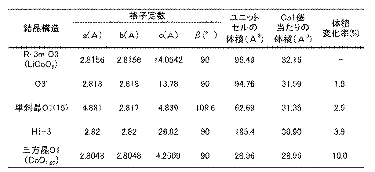
上表のコバルト1個当たりの体積を用いて、同数のコバルト原子あたりで比較した場合、H1−3型結晶構造と放電状態のR−3m O3型結晶構造の体積の差を求めることができる。上表の体積変化率(%)に示すが、分母を放電状態のR−3m O3型結晶構造としたとき、体積の差は3.9%となった。つまり当該体積の差は3.5%を超え、非常に大きいことがわかる。
上表のコバルト1個当たりの体積を用いて、同数のコバルト原子あたりで比較した場合、放電状態のR−3m O3と、O3’型結晶構造の体積の差を求めることができる。上表の体積変化率(%)に示すが、分母を放電状態のR−3m O3型結晶構造としたとき、体積の差は1.8%となった。つまり当該体積の差は、2.5%以下、より詳細には2.2%以下であり、非常に小さいことがわかる。
上表のコバルト1個当たりの体積を用いて、同数のコバルト原子あたりで比較した場合、放電状態のR−3m O3と、単斜晶O1(15)型結晶構造の体積の差を求めることができる。上表の体積変化率(%)に示すが、分母を放電状態のR−3m O3型結晶構造としたとき、体積の差は2.5%となった。つまり当該体積の差は、3.3%以下、より詳細には3.0%以下であり、非常に小さいことがわかる。
このように本発明の一態様の正極活物質では、LixCoO2中のxが小さいとき、つまり多くのリチウムが脱離したときの結晶構造の変化が、従来の正極活物質よりも抑制されている。また同数のコバルト原子あたりで比較した場合の体積の変化も抑制されている。そのため正極活物質は、xが0.24以下になるような充電と、放電とを繰り返しても結晶構造が崩れにくい。そのため、正極活物質は充放電サイクルにおける充放電容量の低下が抑制される。また従来の正極活物質よりも多くのリチウムを安定して利用できるため、正極活物質は重量あたり及び体積あたりの放電容量が大きい。そのため正極活物質を用いることで、重量あたり及び体積あたりの放電容量の高い二次電池を作製できる。
なお本発明の一態様の正極活物質は、LixCoO2中のxが0.15以上0.24以下のときO3’型の結晶構造を有する場合があることが確認され、xが0.24を超えて0.27以下でもO3’型の結晶構造を有すると推定されている。またLixCoO2中のxが0.1を超えて0.2以下、代表的にはxが0.15以上0.17以下のとき単斜晶O1(15)型の結晶構造を有する場合があることが確認されている。しかし結晶構造はLixCoO2中のxだけでなく充放電サイクル数、充放電電流、温度、電解質等の影響を受けるため、必ずしも上記のxの範囲に限定されない。
そのため本発明の一態様の正極活物質はLixCoO2中のxが0.1を超えて0.24以下のとき、O3’型のみを有してもよいし、単斜晶O1(15)型のみを有してもよいし、両方の結晶構造を有してもよい。また本発明の一態様の正極活物質は内部20bの粒子のすべてがO3’型及び/または単斜晶O1(15)型の結晶構造でなくてもよい。他の結晶構造を含んでいてもよいし、一部が非晶質であってもよい。
またLixCoO2中のxが小さい状態にするには、一般的には高い充電電圧で充電する必要がある。そのためLixCoO2中のxが小さい状態を、高い充電電圧で充電した状態と言い換えることができる。本発明の一態様の正極活物質は、高い充電電圧、たとえば25℃において4.6V以上の電圧で充電しても、R−3m O3の対称性を有する結晶構造を保持できるため好ましい、と言い換えることができる。たとえば25℃の環境で、リチウム金属の電位を基準として4.6V以上の電圧で、定電流充電及び定電圧充電(CCCV充電)すると、従来の正極活物質ではH1−3型結晶構造が現れる。そのためリチウム金属の電位を基準として4.6V以上の充電電圧は高い充電電圧ということができる。本明細書等において、特に言及しない場合、充電電圧はリチウム金属の電位を基準として表すとする。
なお、二次電池において例えば負極活物質として黒鉛を用いる場合、上記よりも黒鉛の電位の分だけ二次電池の電圧が低下する。黒鉛の電位はリチウム金属の電位を基準として0.05V乃至0.2V程度である。そのため負極活物質として黒鉛を用いた二次電池の場合は、上記の電圧から黒鉛の電位を差し引いた電圧のとき同様の結晶構造を有する。
<分析方法>
ある正極活物質が、LixCoO2中のxが小さいときO3’型及び/または単斜晶O1(15)型の結晶構造を有する本発明の一態様の正極活物質であるか否かは、LixCoO2中のxが小さい正極活物質を有する正極を、XRD、電子回折、中性子線回折、電子スピン共鳴(Electron Spin Resonance:ESR)、核磁気共鳴(Nuclear Magnetic Resonance:NMR)等を用いて解析することで判断できる。
ある正極活物質が、LixCoO2中のxが小さいときO3’型及び/または単斜晶O1(15)型の結晶構造を有する本発明の一態様の正極活物質であるか否かは、LixCoO2中のxが小さい正極活物質を有する正極を、XRD、電子回折、中性子線回折、電子スピン共鳴(Electron Spin Resonance:ESR)、核磁気共鳴(Nuclear Magnetic Resonance:NMR)等を用いて解析することで判断できる。
特にXRDは、正極活物質が有するコバルト等の遷移金属の対称性を高分解能で解析できる、結晶性の高さ及び結晶の配向性を比較できる、格子の周期性歪み及び結晶子サイズの解析ができる、二次電池を解体して得た正極をそのまま測定しても十分な精度を得られる、等の点で好ましい。
なお粉末XRDで結晶子サイズを解析する場合、加圧等による配向の影響を除いて測定することが好ましい。たとえば二次電池を解体して得た正極から正極活物質を取り出し、粉末サンプルとしてから測定することが好ましい。
また本発明の一態様の正極活物質でも、xが0.1以下など小さすぎる場合、または充電電圧が4.9Vを超えるような条件ではH1−3型または三方晶O1型の結晶構造が生じる場合もある。ただし、xが小さい状態の正極活物質は、大気に触れると結晶構造の変化を起こす場合がある。例えばO3’型及び単斜晶O1(15)型の結晶構造からH1−3型結晶構造に変化する場合がある。そのため、結晶構造の分析に供するサンプルはすべてアルゴン雰囲気等の不活性雰囲気でハンドリングすることが好ましい。
≪充電対象のコインセル≫
ある複合酸化物が、本発明の一態様の正極活物質であるか否かを判断するための充電は、例えば対極リチウムでコインセル(CR2032タイプ、直径20mm高さ3.2mm)を作製して充電することができる。二次電池から取り出した正極を用いてコインセルを作製することも可能である。つまり正極には、正極活物質、導電材及びバインダを混合したスラリーを、アルミニウム箔の正極集電体に塗工されたものを用いる。
ある複合酸化物が、本発明の一態様の正極活物質であるか否かを判断するための充電は、例えば対極リチウムでコインセル(CR2032タイプ、直径20mm高さ3.2mm)を作製して充電することができる。二次電池から取り出した正極を用いてコインセルを作製することも可能である。つまり正極には、正極活物質、導電材及びバインダを混合したスラリーを、アルミニウム箔の正極集電体に塗工されたものを用いる。
対極にはリチウム金属を用いることができる。なお対極にリチウム金属以外の材料を用いたときは、二次電池の電位と正極の電位が異なる。本明細書等における電圧及び電位は、特に言及しない場合、正極の電位である。
電解液が有する電解質には、1mol/Lの六フッ化リン酸リチウム(LiPF6)を用い、電解液には、エチレンカーボネート(EC)とジエチルカーボネート(DEC)がEC:DEC=3:7(体積比)であり、電解液に電解質が溶解したものに対して2wt%のビニレンカーボネート(VC)を混合されたものを用いることができる。
セパレータには厚さ25μmのポリプロピレン多孔質フィルムを用いることができる。
正極缶及び負極缶には、ステンレス(SUS)で形成されているものを用いることができる。
上記条件で作製したコインセルを、任意の電圧(たとえば4.5V、4.55V、4.6V、4.65V、4.7V、4.75Vまたは4.8V)で充電する。任意の電圧で十分に時間をかけて充電できれば充電方法は特に限定されない。たとえば定電流定電圧(CCCV)で充電する場合、CC充電における電流は、20mA/g以上100mA/g以下で行うことができる。CV充電は正極活物質重量あたり2mA/g以上10mA/g以下の電流として終了することができる。正極活物質の相変化を観測するためには、このような小さい電流値で充電を行うことが望ましい。一方で長時間CV充電を行っても電流が2mA/g以上10mA/g以下とならない場合、正極活物質の充電ではなく電解液の分解に電流が消費されていると考えられるため、開始から十分な時間が経過した時点でCV充電を終了してもよい。このときの十分な時間とは、たとえば1.5時間以上3時間以下とすることができる。温度は25℃または45℃とする。このようにして充電した後に、コインセルをアルゴン雰囲気のグローブボックス中で解体して正極を取り出せば、任意の充電容量の正極活物質を得られる。この後に各種分析を行う際、外界成分との反応を抑制するため、アルゴン雰囲気で密封することが好ましい。例えばXRDは、アルゴン雰囲気の密閉容器内に封入して行うことができる。また充電完了後、速やかに正極を取り出し分析に供することが好ましい。具体的には充電完了後1時間以内が好ましく、30分以内がより好ましい。
≪XRD≫
XRDの装置及び条件は特に限定されない。また結晶構造の解析用ソフトウェアについても特に限定されない。精度の高い装置、条件及びそれに対応したソフトウェアを用いるとより正確に結晶構造解析を行うことができ好ましい。たとえば下記のような装置、条件及び解析用ソフトウェアで測定及び解析を行うことができる。
XRD装置 :Bruker AXS社製、D8 ADVANCE
X線源 :CuKα1線
出力 :40kV、40mA
発散角 :Div.Slit、0.5°
検出器:LynxEye
スキャン方式 :2θ/θ連続スキャン
測定範囲(2θ) :15°以上90°以下
ステップ幅(2θ) :0.01°設定
計数時間 :1秒間/ステップ
試料台回転 :15rpm
得られたXRDパターンについて、解析ソフトウェアDIFFRAC.EVA等を用いてバックグラウンドとCuKα2線のピークを除去することができる。
XRDの装置及び条件は特に限定されない。また結晶構造の解析用ソフトウェアについても特に限定されない。精度の高い装置、条件及びそれに対応したソフトウェアを用いるとより正確に結晶構造解析を行うことができ好ましい。たとえば下記のような装置、条件及び解析用ソフトウェアで測定及び解析を行うことができる。
XRD装置 :Bruker AXS社製、D8 ADVANCE
X線源 :CuKα1線
出力 :40kV、40mA
発散角 :Div.Slit、0.5°
検出器:LynxEye
スキャン方式 :2θ/θ連続スキャン
測定範囲(2θ) :15°以上90°以下
ステップ幅(2θ) :0.01°設定
計数時間 :1秒間/ステップ
試料台回転 :15rpm
得られたXRDパターンについて、解析ソフトウェアDIFFRAC.EVA等を用いてバックグラウンドとCuKα2線のピークを除去することができる。
O3’型の結晶構造と、単斜晶O1(15)型の結晶構造と、H1−3型結晶構造のモデルから計算される、CuKα1線による理想的な粉末XRDパターンを図10、図11、図12A及び図12Bに示す。また比較のためLixCoO2中のx=1のLiCoO2 O3と、x=0の三方晶O1の結晶構造から計算される理想的なXRDパターンも示す。図12A及び図12Bは、O3’型結晶構造、単斜晶O1(15)型結晶構造とH1−3型結晶構造のXRDパターンを併記したものであり、図12Aは2θの範囲が18°以上21°以下の領域、図12Bは2θの範囲が42°以上46°以下の領域について拡大したものである。なお、LiCoO2(O3)及びCoO2(O1)のパターンはICSD(Inorganic Crystal Structure DatABase)より入手した結晶構造情報からMaterials Studio(BIOVIA)のモジュールの一つである、Reflex Powder DiffracTionを用いて作成した。2θの範囲は15°から75°とし、Step size=0.01、波長λ1=1.540562×10⁻¹⁰m、λ2は設定なし、Monochromatorはsingleとした。O3’型及び単斜晶O1(15)型の結晶構造のパターンは正極活物質のXRDパターンから結晶構造を推定し、TOPAS ver.3(Bruker社製結晶構造解析ソフトウェア)を用いてフィッティングし、他と同様にXRDパターンを作成した。
図10、図12A及び図12Bに示すように、O3’型の結晶構造では、2θが19.13°以上19.37°未満の範囲、及び2θが45.37°以上45.57°未満の範囲に回折ピークが出現する。
また単斜晶O1(15)型の結晶構造では、2θが19.37°以上19.57°以下の範囲、及び2θが45.57°以上45.67°以下の範囲に回折ピークが出現する。
しかし図11、図12A及び図12Bに示すように、H1−3型結晶構造及び三方晶O1ではこれらの位置に回折ピークは出現しない。そのため、LixCoO2中のxが小さい状態で19.13°以上19.37°未満及び/または19.37°以上19.57°以下、並びに45.37°以上45.57°未満及び/または45.57°以上45.67°以下に回折ピークが出現することは、本発明の一態様の正極活物質の特徴であるといえる。
これは、本発明の一態様の正極活物質ではx=1と、x≦0.24の結晶構造で、XRDの回折ピークが出現する位置が近いということもできる。より具体的には、x=1と、x≦0.24の結晶構造の主な回折ピークのうち2θが42°以上46°以下に出現する回折ピークについて、2θの差が、0.7°以下、より好ましくは0.5°以下であるということができる。
なお、本発明の一態様の正極活物質のXRDパターンについてリートベルト解析を行ったとき、O3’型及び/または単斜晶O1(15)型の結晶構造が50%以上であることが好ましく、60%以上であることがより好ましく、66%以上であることがさらに好ましい。O3’型及び/または単斜晶O1(15)型の結晶構造が50%以上、より好ましくは60%以上、さらに好ましくは66%以上あれば、十分にサイクル特性に優れた正極活物質とすることができる。
また、同様にリートベルト解析を行ったとき、H1−3型及びO1型結晶構造が50%以下であることが好ましい。または34%以下であることが好ましい。または実質的に観測されないことがより好ましい。
また、測定開始から100サイクル以上の充放電を経ても、リートベルト解析を行ったときO3’型及び/または単斜晶O1(15)型の結晶構造が35%以上であることが好ましく、40%以上であることがより好ましく、43%以上であることがさらに好ましい。
またXRDパターンにおける回折ピークの鋭さは結晶性の高さを示す。そのため、充電後の各回折ピークは鋭い、すなわち半値全幅が狭い方が好ましい。たとえば半値全幅が狭い方が好ましい。半値全幅は、同じ結晶相から生じた回折ピークでも、XRDの測定条件及び2θの値によっても異なる。上述した測定条件の場合は、2θ=43°以上46°以下に観測される回折ピークにおいて、半値全幅は例えば0.2°以下が好ましく、0.15°以下がより好ましく、0.12°以下がさらに好ましい。なお必ずしも全ての回折ピークがこの要件を満たしていなくてもよい。一部の回折ピークがこの要件を満たせば、その結晶相の結晶性が高いことがいえる。このような高い結晶性は、十分に充電後の結晶構造の安定化に寄与する。
また、本発明の一態様の正極活物質粒子20が有するO3’型及び単斜晶O1(15)の結晶構造の結晶子サイズは、放電状態のLiCoO2(O3)の1/20程度までしか低下しない。そのため、充放電前の正極と同じXRDの測定条件であっても、LixCoO2中のxが小さいとき明瞭なO3’型及び/または単斜晶O1(15)の結晶構造の回折ピークが確認できる。一方従来のLiCoO2では、一部がO3’型及び/または単斜晶O1(15)の結晶構造に似た構造を取りえたとしても、結晶子サイズが小さくなり、回折ピークはブロードで小さくなる。結晶子サイズは、回折ピークの半値全幅から求めることができる。
≪XPS≫
X線光電子分光(XPS)では、無機酸化物の場合で、X線源として単色アルミニウムのKα線を用いると、表面から2nm乃至8nm程度(通常5nm以下)の深さまでの領域の分析が可能であるため、表層部20aの深さに対して約半分の領域について、各元素の濃度を定量的に分析することができる。また、ナロースキャン分析をすれば元素の結合状態を分析することができる。なおXPSの定量精度は多くの場合±1原子%程度、下限は元素にもよるが約1原子%である。
X線光電子分光(XPS)では、無機酸化物の場合で、X線源として単色アルミニウムのKα線を用いると、表面から2nm乃至8nm程度(通常5nm以下)の深さまでの領域の分析が可能であるため、表層部20aの深さに対して約半分の領域について、各元素の濃度を定量的に分析することができる。また、ナロースキャン分析をすれば元素の結合状態を分析することができる。なおXPSの定量精度は多くの場合±1原子%程度、下限は元素にもよるが約1原子%である。
なお本発明の一態様の正極活物質粒子20の表面及び表層部20aには、正極活物質粒子20作製後に化学吸着した炭酸塩、ヒドロキシ基等は含まないとする。また正極活物質粒子20の表面に付着した電解液、バインダ、導電材、またはこれら由来の化合物も含まないとする。そのため正極活物質が有する元素を定量化するときは、XPSをはじめとする表面分析で検出されうる炭素、水素、過剰な酸素、過剰なフッ素等を除外する補正をしてもよい。例えば、XPSでは結合の種類を解析で分離することが可能であり、バインダ由来のC−F結合を除外する補正をおこなってもよい。
さらに各種分析に供する前に、正極活物質の表面に付着した電解液、バインダ、導電材、またはこれら由来の化合物を除くために、正極活物質及び正極活物質層等の試料に対して洗浄等を行ってもよい。このとき洗浄に用いる溶媒等にリチウムが溶け出す場合があるが、たとえその場合であっても、添加元素は溶け出しにくいため、添加元素の原子数比に影響があるものではない。
また添加元素の濃度は、コバルト濃度と比較してもよい。コバルトとの比を用いることにより、正極活物質を作製後に化学吸着した炭酸塩等の影響を減じて比較することができ好ましい。たとえばXPSの分析によるマグネシウムとコバルトの原子数の比Mg/Coは、0.4以上1.5以下であることが好ましい。一方ICP−MSの分析によるMg/Coは0.001以上0.06以下であることが好ましい。
同様に正極活物質粒子20は、十分にリチウムイオンの挿入脱離の経路を確保するために、表層部20aにおいて各添加元素よりもリチウム及びコバルトの濃度が高いことが好ましい。これはXPS等で測定される表層部20aが有する添加元素から選ばれた一または二以上の各添加元素の濃度よりも、表層部20aのリチウム及びコバルトの濃度が高いことが好ましい、ということができる。たとえばXPS等で測定される表層部20aの少なくとも一部のマグネシウムの濃度よりも、XPS等で測定される表層部20aの少なくとも一部のコバルトの濃度が高いことが好ましい。同様にマグネシウムの濃度よりも、リチウムの濃度が高いことが好ましい。またニッケルの濃度よりも、コバルトの濃度が高いことが好ましい。同様にニッケルの濃度よりも、リチウムの濃度が高いことが好ましい。またアルミニウムよりもコバルトの濃度が高いことが好ましい。同様にアルミニウムの濃度よりも、リチウムの濃度が高いことが好ましい。またフッ素よりもコバルトの濃度が高いことが好ましい。同様にフッ素よりもリチウムの濃度が高いことが好ましい。
さらにアルミニウムは深い領域、たとえば表面、または基準点からの深さが5nm以上50nm以内の領域に広く分布する方がより好ましい。そのため、ICP−MS、GD−MS等を用いた正極活物質粒子20全体の分析ではアルミニウムが検出されるものの、XPS等ではこれの濃度が検出されないか、1原子%以下であると、より好ましい。
XPS分析を行う場合には例えば、X線源として単色化アルミニウムKα線を用いることができる。また、取出角は例えば45°とすることができる。たとえば下記の装置及び条件で測定することができる。
測定装置 :PHI 社製QuanteraII
X線源 :単色化Al Kα(1486.6eV)
検出領域 :100μmφ
検出深さ :約2~5nm(取出角15°~45°)
測定スペクトル :ワイドスキャン,各検出元素のナロースキャン
測定装置 :PHI 社製QuanteraII
X線源 :単色化Al Kα(1486.6eV)
検出領域 :100μmφ
検出深さ :約2~5nm(取出角15°~45°)
測定スペクトル :ワイドスキャン,各検出元素のナロースキャン
また本発明の一態様の正極活物質についてXPS分析したとき、フッ素と他の元素の結合エネルギーを示すピークは682eV以上685eV未満であることが好ましく、684.3eV程度であることがさらに好ましい。これは、フッ化リチウムの結合エネルギーである685eV、及びフッ化マグネシウムの結合エネルギーである686eVのいずれとも異なる値である。
さらに、本発明の一態様の正極活物質についてXPS分析したとき、マグネシウムと他の元素の結合エネルギーを示すピークは、1302eV以上1304eV未満であることが好ましく、1303eV程度であることがさらに好ましい。これは、フッ化マグネシウムの結合エネルギーである1305eVと異なる値であり、酸化マグネシウムの結合エネルギーに近い値である。
またXPSで測定される表層部20aの少なくとも一部において、マグネシウムとフッ素の結合が存在することが好ましく、マグネシウムとフッ素の結合(Mg−F結合)では存在せずに、マグネシウムとフッ素及び酸素の結合(O−Mg−F結合)が存在するとさらに好ましい。表層部20aにおけるマグネシウムとフッ素の結合は、フッ化物による融剤効果が十分に発揮されて、マグネシウムとコバルト酸リチウムの表面が溶融したこと、及びマグネシウムが十分に偏析したことを示す一つの要素である。
XPS測定に用いた励起X線は単色化Al、検出領域は100μmφとすることができる。取出角(サンプル台の傾きと検出器の検出方向のなす角度)は45°または15°とすることができる。取出角45°のときの検出深さはおよそ4~5nm、取出角15°のときの検出深さはおよそ2nmである。
マグネシウム結合状態の一つであるMg1sのXPSスペクトルに、O−Mg−F結合が存在するとは、XPSスペクトルを波形分離した場合、O−Mg−F結合の結合エネルギーがMgOの結合とMgF2の結合の中間になるとして、フィッティングを行う。
取出角45°及び15°のいずれでもO−Mg−F結合が確認されることが好ましい。また取出角45°及び15°において、O−Mg−F結合のピーク値に差が出た場合、XPS検出領域内にてO−Mg−F結合の存在割合が異なるといえる。例えば取出角15°の方が45°より大きいときは、O−Mg−F結合は主に表面から2nmまでのごく浅い領域に存在しているといえる。
≪EDX≫
正極活物質粒子20が有する添加元素から選ばれた一または二以上は濃度勾配を有していることが好ましい。また正極活物質粒子20における添加元素の検出量の最大ピークの位置は、正極活物質粒子20の基準点、代表的には表面からの深さが異なっていることがより好ましい。添加元素の濃度勾配はたとえば、FIB(Focused Ion Beam)等により正極活物質粒子20の断面を露出させ、その断面をEDX、電子プローブ微小分析(EPMA)等を用いて分析することで評価できる。
正極活物質粒子20が有する添加元素から選ばれた一または二以上は濃度勾配を有していることが好ましい。また正極活物質粒子20における添加元素の検出量の最大ピークの位置は、正極活物質粒子20の基準点、代表的には表面からの深さが異なっていることがより好ましい。添加元素の濃度勾配はたとえば、FIB(Focused Ion Beam)等により正極活物質粒子20の断面を露出させ、その断面をEDX、電子プローブ微小分析(EPMA)等を用いて分析することで評価できる。
EDX測定のうち、領域内を走査しながら測定し、領域内を2次元に評価することをEDX面分析と呼ぶ。また線状に走査しながら測定し、原子濃度について正極活物質内の分布を評価することを線分析と呼ぶ。さらにEDXの面分析から、線状の領域のデータを抽出したものを線分析と呼ぶ場合もある。またある領域について走査せずに測定することを点分析と呼ぶ。
EDX面分析(例えば元素マッピング)により、正極活物質粒子20の表層部20a、内部20b及び結晶粒界近傍等における、添加元素の濃度を定量的に分析することができる。また、EDX線分析により、添加元素の分布及びその濃度の最大値を分析することができる。またSTEM−EDXのようにサンプルを薄片化する分析は、奥行き方向の分布の影響を受けずに、特定の領域における正極活物質の表面から中心に向かった深さ方向の濃度分布を分析でき、より好適である。
正極活物質粒子20はリチウムの挿入脱離が可能な遷移金属と酸素を有する化合物であるため、リチウムの挿入脱離に伴い酸化還元する遷移金属M(たとえばCo、Ni、Mn、Fe等)及び酸素が存在する領域と、存在しない領域の界面を、正極活物質の表面とする。正極活物質を分析に供する際、表面に保護膜を付ける場合があるが、保護膜は正極活物質には含まれない。保護膜としては、炭素、金属、酸化物、樹脂などの単層膜または多層膜が用いられる場合がある。
STEM−EDX線分析等では、原理的に、または測定誤差のため、元素の特性X線の検出量のグラフが急峻な変化とならず、厳密に表面を決めることが難しい場合がある。そのためSTEM−EDX線分析等において深さ方向に言及する際は、上記遷移金属Mが、内部の検出量の平均値MAVEと、バックグラウンドの平均値MBGとの和の50%になる点、及び酸素が、内部の検出量の平均値OAVEと、バックグラウンドの平均値OBGとの和の50%になる点を基準点とする。なお、上記遷移金属Mと酸素で、内部とバックグラウンドの和の50%の点が異なる場合は、表面に付着する酸素を含む金属酸化物、炭酸塩等の影響と考えられるため、上記遷移金属Mの内部の検出量の平均値MAVEと、バックグラウンドの平均値MBGとの和の50%の点を採用することができる。また遷移金属Mを複数有する正極活物質の場合、内部20bにおけるカウント数が最も多い元素のMAVE及びMBGを用いて上記基準点を求めることができる。
上記遷移金属Mのバックグラウンドの平均値MBGは、たとえば遷移金属Mの検出量が増加を始める近辺を避けて正極活物質の外側の2nm以上、好ましくは3nm以上の範囲を平均して求めることができる。また内部の検出量の平均値MAVEは、遷移金属M及び酸素のカウントが飽和し安定した領域、たとえば遷移金属Mの検出量が増加を始める領域から深さ30nm以上、好ましくは50nmを超える部分で、2nm以上、好ましくは3nm以上の範囲を平均して求めることができる。酸素のバックグラウンドの平均値OBG及び酸素の内部の検出量の平均値OAVEも同様に求めることができる。
また断面STEM(走査型透過電子顕微鏡)像等における正極活物質粒子20の表面とは、正極活物質の結晶構造に由来する像が観察される領域と、観察されない領域の境界であって、正極活物質を構成する金属元素の中でリチウムより原子番号の大きな金属元素の原子核に由来する原子カラムが確認される領域の最も外側とする。STEM像等における表面は、より空間分解能の高い分析と併せて判断してもよい。
またSTEM−EDX線分析におけるピークとは、元素毎の特性X線強度のグラフに現れる特性X線の極大値(凸形状の頂点)であり、ピークが複数確認された場合は特性X線の最大値をいうこととする。なおSTEM−EDX線分析におけるノイズとしては、空間分解能(R)以下、たとえばR/2以下の半値全幅の測定値などを用いると好ましい。
同一箇所を同一条件で複数回スキャンすることでノイズの影響を軽減できる。たとえば6スキャン測定した積算値を各元素の検出量とすることができる。スキャン回数は6に限られず、それ以上行って、その平均を各元素の検出量とすることもできる。
STEM−EDX線分析の対象となるサンプルは、たとえば以下のように作製する。まず正極活物質の表面に保護膜を蒸着する。たとえばイオンスパッタ装置(日立ハイテク製MC1000)のカーボンコーティングユニットにて、炭素を蒸着することができる。
次に正極活物質を薄片化しSTEM断面試料を作製する。たとえばFIB−SEM(装置(日立ハイテク製XVision200TBS)にて薄片化加工を行うことができる。その際ピックアップはMPS(マイクロプロービングシステム)で行い、仕上げ加工の条件はたとえば加速電圧10kVとすることができる。
STEM−EDX線分析における空間分解能を高くするためには、電子ビームのビーム径(ビーム直径、プローブ径、又はプローブ直径ともいう)が小さいことが好ましい。STEM−EDX線分析におけるビーム径としては、0.3nm以下であることが好ましく、0.2nm以下であることがより好ましく、0.1nm以下であることが更に好ましい。ビーム径を小さくするために、収差補正を実施すると好ましい。具体的には光学系に収差補正機構(Cs−コレクタ)を配置する。
STEM−EDX線分析は、たとえばSTEM装置(日立ハイテク製HD−2700)を用いて、EDX検出器は、EDAXのOctane T Ultra W(Dual EDS)を使用することができる。EDX線分析時は、STEM装置の加速電圧を200kV、エミッション電流が6μA以上10μA以下になるよう設定し、薄片化した試料のうち奥行き及び凹凸の少ない箇所を測定する。倍率はたとえば15万倍程度とする。
<被覆部>
正極活物質粒子20の表面の少なくとも一部に、被覆部が付着していてもよい。図13に被覆部24が付着した正極活物質粒子20の断面図を示す。
正極活物質粒子20の表面の少なくとも一部に、被覆部が付着していてもよい。図13に被覆部24が付着した正極活物質粒子20の断面図を示す。
被覆部24はたとえば充放電に伴い電解質及び電解液の分解物が堆積して形成されたものであることが好ましい。特にLixCoO2中のxが0.24以下となるような充電を繰り返す場合、正極活物質粒子20の表面に電解液由来の被覆部を有することで、充放電サイクル特性が向上することが期待される。これは正極活物質表面のインピーダンスの上昇を抑制する、またはコバルトの溶出を抑制する、等の理由による。被覆部24はたとえば炭素、酸素及びフッ素を有することが好ましい。さらに電解液にLiBOB、及び/またはSUN(スベロニトリル)を用いた場合などは良質な被覆部を得られやすい。そのため、ホウ素、窒素、硫黄及びフッ素から選ばれた一または二以上を有する被覆部24は良質な被覆部である場合があり好ましい。また被覆部24は正極活物質粒子20の全てを覆っていなくてもよい。たとえば、正極活物質粒子20の表面の50%以上を覆っていればよく、70%以上であればより好ましく、90%以上であればさらに好ましい。
≪DCIR(Direct Current Internal Resistence、直流抵抗)≫
上記の≪充電方法≫において、ある複合酸化物が、本発明の一態様の正極活物質であるか否かを判断するための充電として、対極リチウムでコインセル(CR2032タイプ、直径20mm高さ3.2mm)を作製して充電することを説明している。同様に作製されるコインセルを用いて、本発明の一態様の正極活物質の特徴の一つである抵抗DCIRが小さいことを測定することが可能である。
上記の≪充電方法≫において、ある複合酸化物が、本発明の一態様の正極活物質であるか否かを判断するための充電として、対極リチウムでコインセル(CR2032タイプ、直径20mm高さ3.2mm)を作製して充電することを説明している。同様に作製されるコインセルを用いて、本発明の一態様の正極活物質の特徴の一つである抵抗DCIRが小さいことを測定することが可能である。
上記の≪充電方法≫と同じ条件で作製したコインセルを、任意の電圧(たとえば4.50V、4.55V、4.60V、4.65V、4.70V、4.75Vまたは4.80V)で充電する。任意の電圧で十分に時間をかけて充電できれば充電方法は特に限定されない。たとえばCCCVで充電する場合、CC充電における電流は、20mA/g以上100mA/g以下で行うことができる。CV充電は2mA/g以上10mA/g以下で終了することができる。
充電されたコインセルを充電及び放電の何れも行わない状態とする。これを休止期間と呼び、休止期間は5分以上30分以下が好ましい。その後、抵抗DCIRの測定を行う。抵抗DCIRの測定は、正極活物質の重量あたり2mA/g以上10mA/g以下の電流、代表的には6mA/gの電流で1秒間放電することで測定しており、放電前の開回路電圧と放電中の電圧との差を上記の電流(例えば6mA/g)で除して求めることができる。
上記放電前(充電後)の開回路電圧が4.50V以上4.60V以下の場合に、本発明の一態様の正極活物質を有するコインセルの抵抗DCIRは、好ましくは40Ω以下であり、さらに好ましくは25Ω以下である。なお、抵抗DCIRに関する一連の測定は、充放電サイクル試験又はレート別放電容量試験と同じ温度環境で行うとよく例えば25℃環境下、又は45℃環境下で行うことがある。
≪粉体抵抗測定≫
本発明の一態様の正極活物質粒子20は、高い電圧においても安定な結晶構造を有する。充電状態において正極活物質の結晶構造が安定であることにより、充放電の繰り返しに伴う充放電容量の低下を抑制することができる。上記のように優れた特性を有する正極活物質粒子20の特徴として、上記の<<XRD>>において、LixCoO2中のxが小さいときO3’型及び/または単斜晶O1(15)型の結晶構造を有することを説明した。
本発明の一態様の正極活物質粒子20は、高い電圧においても安定な結晶構造を有する。充電状態において正極活物質の結晶構造が安定であることにより、充放電の繰り返しに伴う充放電容量の低下を抑制することができる。上記のように優れた特性を有する正極活物質粒子20の特徴として、上記の<<XRD>>において、LixCoO2中のxが小さいときO3’型及び/または単斜晶O1(15)型の結晶構造を有することを説明した。
本発明の一態様の正極活物質粒子20の特徴として、正極活物質粒子20の粉体における体積抵抗率は、64MPaの圧力において1.0×10⁸Ω・cm以上1.0×10¹⁰Ω・cm以下であることが好ましく、5.0×10⁸Ω・cm以上1.5×10⁹Ω・cm以下であることがより好ましい。
上記の体積抵抗率を有する正極活物質粒子20は、高い電圧においても安定な結晶構造を有し、充電状態において正極活物質の結晶構造が安定であるために重要である表層部20aを、良好に形成できたことを示す指標とすることができる。
本発明の一態様の正極活物質粒子20の粉体における体積抵抗率の測定方法について説明する。
粉体の体積抵抗率の測定は、抵抗測定用の端子を有する機器部分と、測定対象である粉体に圧力を加える機構と、を有することが好ましい。抵抗測定用の端子としては4端子(4探針ともいう)を有することが好ましい。抵抗測定用の端子と、測定対象である粉体(サンプル)に圧力を加える機構と、を有する測定装置として例えば、三菱化学アナリテック社製のMCP−PD51を用いることができる。抵抗測定機器は低抵抗測定器ロレスタ−GPまたは高抵抗測定器ハイレスタ−GPを用いることができる。ロレスタ−GPは低抵抗サンプルの測定に用いることができ、ハイレスタ−GPは高抵抗サンプルの測定に用いることができる。なお、測定環境として、ドライルームなどの安定した環境であることが好ましい。ドライルームの環境として、例えば25℃の温度環境、かつマイナス40℃以下の露点環境であることが好ましい。湿度の高い環境で測定を行う場合、大気中の水分の影響で電気抵抗が下がり、本来の物性値が得られない可能性がある。
上記に示す測定装置を用いる粉体の体積抵抗率の測定について説明する。まず、粉体サンプルを測定部にセットする。測定部において、粉体サンプルと、抵抗測定用の端子と、が接する構造となっており、かつ粉体サンプルに圧力を加えることが可能な構造となっている。また、測定部における粉体サンプルの体積を測定するための構造も有している。具体的には、上記の測定部は円筒状の空間を有し、該空間に粉体サンプルがセットされる。上記した粉体サンプルの体積を測定するための構造は、該空間にセットされた粉体の高さを計測することで、その時の粉体が占める体積を測定することが可能である。
粉体の体積抵抗率の測定において、粉体に圧力を加えた状態で、粉体の電気抵抗測定と、粉体の体積計測を実施する。粉体に加える圧力は、複数条件で実施することができる。例えば、16MPa、25MPa、38MPa、51MPa、及び64MPaのそれぞれの圧力条件において、粉体の電気抵抗と、粉体の体積と、を計測することができる。計測した粉体の電気抵抗と粉体の体積の値から、粉体の体積抵抗率を算出することができる。
上記に示すような測定をおこなう場合、本発明の一態様の正極活物質粒子20の粉体における体積抵抗率が、64MPaの加圧下で測定したとき1.0×10⁸Ω・cm以上1.0×10¹⁰Ω・cm以下である場合に、高い充電電圧条件での充放電サイクル試験において、好ましいサイクル特性を示し、5.0×10⁸Ω・cm以上1.5×10⁹Ω・cm以下である場合に、高い電圧条件での充放電サイクル試験において、さらに好ましいサイクル特性を示す。
なお本発明書等で特に言及しない場合、上記のように測定した体積抵抗率は、粉体の体積抵抗率である。
<釘刺し試験>
次に釘刺し試験について説明する。釘刺し試験とは二次電池を満充電状態として、2mm以上20mm以下から選ばれた所定の直径を満たす釘を、所定の速度で二次電池へ刺しこむ試験である。満充電とは、State Of Charge(以下、SOCと記す)で表される充電率が100%である状態を指す。本実施の形態では、まず釘刺し試験装置について説明する。
次に釘刺し試験について説明する。釘刺し試験とは二次電池を満充電状態として、2mm以上20mm以下から選ばれた所定の直径を満たす釘を、所定の速度で二次電池へ刺しこむ試験である。満充電とは、State Of Charge(以下、SOCと記す)で表される充電率が100%である状態を指す。本実施の形態では、まず釘刺し試験装置について説明する。
図14Aには、釘刺し試験装置1000の横面図を示す。釘刺し試験装置1000は、ステージ1001と、駆動部1002と、釘1003と、電圧測定器1015と、温度測定器1016と、制御部1018と、を有する。駆動部1002は、釘1003を図中矢印方向に動作させる駆動機構1012を有し、駆動機構1012により、釘1003がステージ1001上に設置される二次電池1004を貫通するように動作する。このとき二次電池1004は満充電状態としておき、この動作を釘刺し動作と呼ぶ。なお、図14A中に示す破線は、釘1003が、釘刺し動作において、二次電池1004を貫通した釘1003を収容するために設けられた、ステージ1001の凹部を示している。
電圧測定器1015から釘刺し動作中の二次電池の電圧に関する情報が制御部1018に送信される。具体的には電圧変化量等が制御部1018に送信される。また温度測定器1016から釘刺し動作中の温度に関する情報が制御部1018に送信される。制御部1018は、釘1003の動作条件を制御する場合、駆動部1002へ制御信号を送信することができる。
図14Bは、釘刺し試験装置1000の、ステージ1001の上部付近を説明する斜視図である。ステージ1001上に設置される二次電池1004は、配線1005a及び配線1005bと、電気的に接続される。なお配線1005a及び配線1005bは、電圧測定器1015が有するものであり、当該配線1005a及び配線1005bはそれぞれ、二次電池1004の正極側タブ、及び負極側タブと電気的に接続され、二次電池1004の電圧を測定することができる。二次電池1004の電圧を、単に電圧、正負極間の電圧値、電池電圧、セル電圧、又は開放電圧と呼ぶ。また温度測定器1016として温度センサを用いる場合、温度センサが二次電池1004の外装体の表面に接するように設ける。
図14Bでは二次電池1004に第1の温度センサ1006a及び第2の温度センサ1006bを配置し、さらに図14Aに示す釘1003に第3の温度センサ1006cを設けた例を示すが、二次電池1004における温度センサは1つ、又は3つ以上配置してもよい。二次電池1004において、配線1005a及び配線1005bが配置されない辺側に第1の温度センサ1006aを設け、配線1005a及び配線1005bが配置された辺側に第2の温度センサ1006bを設ける。このように2以上の温度センサを配置すると、外装体の膨張等により一の温度センサが使用できなくなった場合であっても、他の温度センサを使用することができるため好ましい。
さらに配線1005a及び配線1005bが配置された辺には溶着領域があるが、配線1005a及び配線1005bが配置されない辺では外装体は折り返されるため、上記接着領域がない。したがって外装体が膨張した場合であっても、配線1005a及び配線1005bが配置されない辺では膨張が抑制され、第2の温度センサ1006bは第1の温度センサ1006aよりも剥がれにくく好ましい。
図14B中に示す破線の楕円は、釘刺し動作において、釘1003が二次電池1004を貫通する領域である。二次電池1004に設けられる第1の温度センサ1006a及び第2の温度センサ1006bは、釘1003が貫通する領域から等距離となるように設けるとよい。代表的には、釘1003が貫通する領域から5cm以内、好ましくは2cm以内に、第1の温度センサ1006a及び第2の温度センサ1006bを設けるとよい。このようにセンサを設けることで、釘1003が貫通する領域及びその近傍の温度変化を把握することができ好ましい。ここでいう近傍とは、貫通する領域から1cm以内の領域を言う。なお温度センサを2以上配置する場合、互いの温度センサが示す温度の差が±5℃以内、好ましくは±2℃以内であることを確認してから釘刺し動作を開始すると好ましい。
釘刺し試験で非発火となる、又は熱暴走に至らないようにするには、二次電池の温度上昇を抑制すること、負極、正極及び/又は電解液が高温時に安定な特性を持つと好ましい。温度上昇を抑制する構成とは、電流の速度を緩やかにさせる正極活物質の構造が挙げられる。具体的には正極活物質の表層部にマグネシウム等の添加元素が偏析した構成等により、電流の速度を緩やかにさせることができる。
<釘刺し試験における二次電池の特徴>
二次電池において満充電状態で交流インピーダンス測定を行った際、周波数1kHzのときに交流インピーダンス値が100mΩ以下、好ましくは90mΩ未満の内部抵抗が好ましい。このような内部抵抗を有する二次電池は安全性の高いといえる。満充電状態のとき二次電池の充電容量は2000mAh以上、好ましくは2400mAh以上を満たすと好ましい。当該満充電状態の二次電池は経過時間に伴い放電することがあるため、満充電状態としてから24時間以内、好ましくは12時間以内、さらに好ましくは6時間以内に交流インピーダンス測定を行うとよい。
二次電池において満充電状態で交流インピーダンス測定を行った際、周波数1kHzのときに交流インピーダンス値が100mΩ以下、好ましくは90mΩ未満の内部抵抗が好ましい。このような内部抵抗を有する二次電池は安全性の高いといえる。満充電状態のとき二次電池の充電容量は2000mAh以上、好ましくは2400mAh以上を満たすと好ましい。当該満充電状態の二次電池は経過時間に伴い放電することがあるため、満充電状態としてから24時間以内、好ましくは12時間以内、さらに好ましくは6時間以内に交流インピーダンス測定を行うとよい。
本実施の形態は、他の実施の形態と組み合わせ用いることができる。
(実施の形態3)
本実施の形態では、図15及び図16を用いて本発明の一態様の正極の製造方法について説明する。なお本実施の形態では、繊維状の導電材を用いた正極の製法方法について説明する。
本実施の形態では、図15及び図16を用いて本発明の一態様の正極の製造方法について説明する。なお本実施の形態では、繊維状の導電材を用いた正極の製法方法について説明する。
《正極の作製方法1》
<ステップS11>
図15に示すステップS11では、繊維状の導電材1を用意する。繊維状の導電材1として、CNTを用いることとする。さらにCNTの水分を除去するために、乾燥処理を行うとよい。乾燥処理には自然乾燥が含まれるが、好ましい温度は100℃以上200℃以下、より好ましくは150℃以上200℃以下で加熱すると好ましい。さらに本ステップにおける乾燥時間は、12時間以上、好ましくは24時間以上が好ましい。
<ステップS11>
図15に示すステップS11では、繊維状の導電材1を用意する。繊維状の導電材1として、CNTを用いることとする。さらにCNTの水分を除去するために、乾燥処理を行うとよい。乾燥処理には自然乾燥が含まれるが、好ましい温度は100℃以上200℃以下、より好ましくは150℃以上200℃以下で加熱すると好ましい。さらに本ステップにおける乾燥時間は、12時間以上、好ましくは24時間以上が好ましい。
ステップS11では、さらに有機溶媒2及び分散剤3を用意する。有機溶媒2として代表的にはNMPを用意すると好ましい。分散剤3として代表的にはPVPを用意すると好ましい。繊維状の導電材1としてCNTを用いた場合、CNT:PVP:NMP=x:y:(100−x−y)(重量比)(0<(x+y)<100)としたとき、0.1<x<5であると好ましい。CNTの割合が多すぎると、PVPを添加しても凝集がほどけず、均一な分散液を得られない。また、0<y<1であると好ましい。PVPの割合が多すぎると、バインダの割合を減らすこととなり、電極の結着性を低下させうる。
<ステップS12>
図15に示すステップS12では、超音波処理を行って繊維状の導電材1を分散させる。繊維状の導電材1としてCNTを用いた場合、超音波処理により凝集したCNT同士の界面をはがすことができる。超音波処理の条件として、20kHzとすると好ましい。ただし超音波処理の具体的な条件は何ら限定されるものではない。本ステップにて分散剤3を加えたことにより、CNTの再凝集が抑制され、有機溶媒2へ適切に分散するため好ましい。
図15に示すステップS12では、超音波処理を行って繊維状の導電材1を分散させる。繊維状の導電材1としてCNTを用いた場合、超音波処理により凝集したCNT同士の界面をはがすことができる。超音波処理の条件として、20kHzとすると好ましい。ただし超音波処理の具体的な条件は何ら限定されるものではない。本ステップにて分散剤3を加えたことにより、CNTの再凝集が抑制され、有機溶媒2へ適切に分散するため好ましい。
<ステップS13>
上記ステップS12を経て、繊維状の導電材1の分散性が良好な分散液X1を得ることができる。
上記ステップS12を経て、繊維状の導電材1の分散性が良好な分散液X1を得ることができる。
<ステップS15>
図15に示すステップS15では、正極活物質21を用意する。正極活物質21は本発明の一態様の正極活物質粒子を用いればよい。ステップS15ではさらに、バインダ4及び有機溶媒5を用意する。バインダ4は上記実施の形態で述べたものから選択することができる。有機溶媒5はNMPを用意する。
図15に示すステップS15では、正極活物質21を用意する。正極活物質21は本発明の一態様の正極活物質粒子を用いればよい。ステップS15ではさらに、バインダ4及び有機溶媒5を用意する。バインダ4は上記実施の形態で述べたものから選択することができる。有機溶媒5はNMPを用意する。
<ステップS16>
図15に示すステップS16では、分散液X1,正極活物質21、バインダ4及び有機溶媒5を混合する。本ステップでは、ポリプロピレン製容器(PP製容器)に上記材料を入れて、自転・公転方式ミキサーにより混合する。その後、スパチュラを用いた混練作業を追加すると好ましい。さらに自転・公転方式ミキサー及びスパチュラによる混練作業を繰り返すとよい。このような混合により、繊維状の導電材1の分散性を維持しながら、繊維状の導電材1の解砕を抑制することができる。
図15に示すステップS16では、分散液X1,正極活物質21、バインダ4及び有機溶媒5を混合する。本ステップでは、ポリプロピレン製容器(PP製容器)に上記材料を入れて、自転・公転方式ミキサーにより混合する。その後、スパチュラを用いた混練作業を追加すると好ましい。さらに自転・公転方式ミキサー及びスパチュラによる混練作業を繰り返すとよい。このような混合により、繊維状の導電材1の分散性を維持しながら、繊維状の導電材1の解砕を抑制することができる。
<ステップS17>
図15に示すステップS17では、ステップS11及びステップS12を経て得られた分散液X2(分散液X1と同じ組成のもの)をさらに追加する。ステップS15の混合における対象物の粘度を調整しやすくなる。さらに繊維状の導電材1の分散性が良好な分散液X2を新たに追加するため、繊維状の導電材1の分散性が損なわれにくいため好ましい。
図15に示すステップS17では、ステップS11及びステップS12を経て得られた分散液X2(分散液X1と同じ組成のもの)をさらに追加する。ステップS15の混合における対象物の粘度を調整しやすくなる。さらに繊維状の導電材1の分散性が良好な分散液X2を新たに追加するため、繊維状の導電材1の分散性が損なわれにくいため好ましい。
<ステップS18及びステップS19>
図15に示すステップS18では、攪拌し、必要に応じてステップS19で分散液の粘度を調整する。粘度の調整として、有機溶媒5を蒸発させる方法が挙げられる。
図15に示すステップS18では、攪拌し、必要に応じてステップS19で分散液の粘度を調整する。粘度の調整として、有機溶媒5を蒸発させる方法が挙げられる。
<ステップS20>
図15に示すステップS20では、正極用スラリー30を得る。正極用スラリー30における粘度は、正極用スラリー30の固形分比を用いて確かめることができる。正極用スラリー30の固形分率は50%以上85%以下が好ましく、60%以上80%以下であるとより好ましい。
図15に示すステップS20では、正極用スラリー30を得る。正極用スラリー30における粘度は、正極用スラリー30の固形分比を用いて確かめることができる。正極用スラリー30の固形分率は50%以上85%以下が好ましく、60%以上80%以下であるとより好ましい。
このようにして繊維状の導電材の分散性が良好な正極用スラリーを得ることができる。正極用スラリーにおいて、繊維状の導電材、代表的にはCNTは解砕されることが抑制されるため、正極の強度を高めることができる。
《正極の作製方法2》
<ステップS17>
図16に示すステップS11乃至ステップS16は、図15に示すステップS11乃至ステップS16と同様である。正極の作製方法2はステップS17として、先に入れた正極活物質21と異なる正極活物質21bを用意する。異なる正極活物質21bとして、粒子径が異なるものを用意する。
<ステップS17>
図16に示すステップS11乃至ステップS16は、図15に示すステップS11乃至ステップS16と同様である。正極の作製方法2はステップS17として、先に入れた正極活物質21と異なる正極活物質21bを用意する。異なる正極活物質21bとして、粒子径が異なるものを用意する。
その後、図16に示すステップS19は、図15に示すステップS19と同様であり、ステップS20として正極用スラリー30bを得る。正極用スラリー30bにおける粘度は、正極用スラリー30bの固形分比を用いて確かめることができる。正極用スラリー30bの固形成分が55%以上85%以下が好ましく65%以上80%以下であるとより好ましい。
このようにして繊維状の導電材1の分散性が良好な正極用スラリーであって、繊維状の導電材1が正極活物質21を積極的に包んだ構成を得ることができる。正極用スラリーにおいて、繊維状の導電材1、代表的にはCNTは解砕されることが抑制されるため、十分な電極強度を有する正極を得ることができる。
本実施の形態は、他の実施の形態と組み合わせ用いることができる。
(実施の形態4)
本実施の形態では、図17乃至図20を用いて本発明の一態様の複数の正極活物質粒子を有する正極活物質21の製造方法について説明する。
本実施の形態では、図17乃至図20を用いて本発明の一態様の複数の正極活物質粒子を有する正極活物質21の製造方法について説明する。
《正極活物質の作製方法1》
<ステップS110>
図17に示すステップS110では、出発材料として、リチウム源(図中Li源)及びコバルト源(図中Co源)を用意する。リチウム源としては、リチウムを有する化合物を用いると好ましく、例えば炭酸リチウム、水酸化リチウム、硝酸リチウム、又はフッ化リチウム等を用いることができる。リチウム源は純度が高いと好ましく、例えば純度が3N(99.9%)以上、好ましくは4N(99.99%)以上の材料を用いるとよい。コバルト源としては、コバルトを有する化合物を用いると好ましく、例えば四酸化三コバルト等の酸化コバルト、水酸化コバルト等を用いることができる。コバルト源は純度が高いと好ましく、例えば純度が3N(99.9%)以上、好ましくは4N(99.99%)以上、より好ましくは4N5(99.995%)以上の材料を用いるとよい。高純度の材料を用いることで、正極活物質の不純物を制御することができる。その結果、充放電サイクルにおける放電容量の低下を抑制することができる。さらに、二次電池の信頼性が向上するといった効果も奏する。
<ステップS110>
図17に示すステップS110では、出発材料として、リチウム源(図中Li源)及びコバルト源(図中Co源)を用意する。リチウム源としては、リチウムを有する化合物を用いると好ましく、例えば炭酸リチウム、水酸化リチウム、硝酸リチウム、又はフッ化リチウム等を用いることができる。リチウム源は純度が高いと好ましく、例えば純度が3N(99.9%)以上、好ましくは4N(99.99%)以上の材料を用いるとよい。コバルト源としては、コバルトを有する化合物を用いると好ましく、例えば四酸化三コバルト等の酸化コバルト、水酸化コバルト等を用いることができる。コバルト源は純度が高いと好ましく、例えば純度が3N(99.9%)以上、好ましくは4N(99.99%)以上、より好ましくは4N5(99.995%)以上の材料を用いるとよい。高純度の材料を用いることで、正極活物質の不純物を制御することができる。その結果、充放電サイクルにおける放電容量の低下を抑制することができる。さらに、二次電池の信頼性が向上するといった効果も奏する。
<ステップS112>
図17に示すステップS112として、リチウム源及びコバルト源を粉砕しながら混合する。本ステップにより、リチウム源及びコバルト源を有する混合材料が得られる。粉砕しながら混合する方式は、乾式または湿式があり、湿式はより小さく粉砕することができる点が乾式より優れている。湿式で行う場合は、溶媒を準備する。溶媒としてはアセトン等のケトン、エタノール及びイソプロパノール等のアルコール、エーテル、ジオキサン、アセトニトリル、N−メチル−2−ピロリドン(NMP)等を用いることができる。溶媒は、リチウムと反応が起こりにくい、非プロトン性溶媒を用いることがより好ましい。本実施の形態では、純度が99.5%以上の脱水アセトンを用いることとする。脱水アセトンは水分含有量を10ppm以下まで抑えものである。脱水アセトンにリチウム源及びコバルト源を混合して、粉砕しながら混合することで、混合材料への不純物混入を低減することができる。
図17に示すステップS112として、リチウム源及びコバルト源を粉砕しながら混合する。本ステップにより、リチウム源及びコバルト源を有する混合材料が得られる。粉砕しながら混合する方式は、乾式または湿式があり、湿式はより小さく粉砕することができる点が乾式より優れている。湿式で行う場合は、溶媒を準備する。溶媒としてはアセトン等のケトン、エタノール及びイソプロパノール等のアルコール、エーテル、ジオキサン、アセトニトリル、N−メチル−2−ピロリドン(NMP)等を用いることができる。溶媒は、リチウムと反応が起こりにくい、非プロトン性溶媒を用いることがより好ましい。本実施の形態では、純度が99.5%以上の脱水アセトンを用いることとする。脱水アセトンは水分含有量を10ppm以下まで抑えものである。脱水アセトンにリチウム源及びコバルト源を混合して、粉砕しながら混合することで、混合材料への不純物混入を低減することができる。
粉砕及び混合の手段にはボールミル、またはビーズミル等を用いることができる。ビーズミルは攪拌機構を用いた手段である。ボールミルは、メディアをいれたポットを回転させる手段である。メディアには酸化アルミニウムボール又は酸化ジルコニウムボールを用いると好ましい。代表的な酸化ジルコニウムボールは、不純物の排出が少な材料であるため、メディアからのコンタミネーションが少ない。さらに、メディアからのコンタミネーションを抑制するためにボールミルのポットの周速を100mm/s以上2000mm/s以下とすると好ましい。
<ステップS113>
図17に示すステップS113として、上記混合材料を加熱する。加熱は、800℃以上1100℃以下で行うことが好ましく、900℃以上1000℃以下で行うことがより好ましく、950℃程度がさらに好ましい。温度が低すぎると、リチウム源及びコバルト源の溶融が不十分となるおそれがある。一方温度が高すぎると、リチウム源からリチウムが昇華して減少することがあり、またコバルトが過剰に還元されることもある。例えばコバルトが3価から2価へ還元されると、酸素欠陥などが誘発されることがある。このように温度が高すぎることは正極活物質の製造方法にとって好ましくない。
図17に示すステップS113として、上記混合材料を加熱する。加熱は、800℃以上1100℃以下で行うことが好ましく、900℃以上1000℃以下で行うことがより好ましく、950℃程度がさらに好ましい。温度が低すぎると、リチウム源及びコバルト源の溶融が不十分となるおそれがある。一方温度が高すぎると、リチウム源からリチウムが昇華して減少することがあり、またコバルトが過剰に還元されることもある。例えばコバルトが3価から2価へ還元されると、酸素欠陥などが誘発されることがある。このように温度が高すぎることは正極活物質の製造方法にとって好ましくない。
加熱時間は短すぎるとコバルト酸リチウムが合成されないことがあり好ましくないが、長すぎると生産性が低下すると考えらえる。そこで加熱時間は1時間以上50時間以下が好ましく、2時間以上20時間以下とすることがさらに好ましい。
昇温レートは、加熱温度の到達温度によるが、80℃/h以上250℃/h以下がよい。たとえば1000℃で10時間加熱する場合、昇温レートは200℃/hとすると好ましい。
複合酸化物の加熱のため、雰囲気は酸素を有すると好ましい。さらに雰囲気は水が少ないことが好ましく、代表的には加熱雰囲気を乾燥空気とすると好ましい。例えば炉内に乾燥空気を導入し続ける方法がある。この場合、乾燥空気の流量は5L/min以上20L/min以下とすることが好ましい。上記のように雰囲気用のガスを炉へ導入し続け、ガスが炉内を流れている方法をフローと呼ぶ。またフローさせないやり方として、炉を減圧してから雰囲気用のガスを充填し(パージし、といってもよい)、当該ガスが炉から出入りしないようにする方法を用いてもよい。例えば炉が有する差圧計が−970hPaとなるまで減圧してから、50hPaになるまで雰囲気用のガスを炉に充填すると好ましい。パージの場合も雰囲気用のガスには乾燥空気を適用することができる。
加熱後の冷却は自然放冷でよいが、規定温度から室温までの降温時間が10時間以上50時間以下に収まると好ましい。ただし、必ずしも室温までの冷却は要せず、次のステップが許容する温度まで冷却されればよい。
加熱に用いる炉として、ロータリーキルン又はローラーハースキルンを用いてもよい。ロータリーキルンによる加熱は、連続式、バッチ式いずれの場合でも攪拌しながら加熱することができる。
加熱の際に混合材料を収容する容器は、るつぼまたはセッター(さやともいう)が好ましい。容器の純度は3N(99.9%)以上、好ましくは4N(99.99%)以上が好ましい。なお、容器に蓋を配置してから加熱することで、材料の不要な揮発を防ぐことができる。また、るつぼ及びセッターの材質として、酸化アルミニウム、酸化ジルコニウム又はムライト−コーディライトを用いてもよい。
また容器は新品のものよりも、複数回使用した容器を用いることが好ましい。本明細書等において新品の容器とは、リチウム、混合材料を入れて加熱する工程が2回以下のものをいう。また複数回使用した容器とは、混合材料を入れて加熱する工程を3回以上経たものという。新品の容器を用いると、加熱の際に材料の一部が容器に吸収されるおそれ、及び/または当該材料の一部が容器に付着するおそれがあるためである。材料の一部が失われると、良質な正極活物質が得られない懸念が高まる。一方で複数回使用した容器では上記おそれが少なく、充放電サイクルにおける放電容量の低下が抑制されることがある。
加熱が終わったあと、必要に応じて解砕し、さらにふるいを実施してもよい。加熱後の材料を回収する際に、混合材料を容器から乳鉢へ移動させたのち回収してもよい。また、当該乳鉢は酸化アルミニウムのものを用いると好適である。
<ステップS114>
上述のステップを経て、図17に示すステップS114のように、コバルト酸リチウムを合成することができる。コバルト酸リチウムの粒子径、又はメディアン径(D50)は10μm以下とすると、充放電サイクルにおける放電容量の低下が抑制されるため好ましい。
上述のステップを経て、図17に示すステップS114のように、コバルト酸リチウムを合成することができる。コバルト酸リチウムの粒子径、又はメディアン径(D50)は10μm以下とすると、充放電サイクルにおける放電容量の低下が抑制されるため好ましい。
ステップS110乃至ステップS114のように固相法でコバルト酸リチウムを作製する例を示したが、共沈法でコバルト酸リチウムを作製してもよい。また水熱法でコバルト酸リチウムを作製してもよい。
なお、ステップS114としてあらかじめ合成されたコバルト酸リチウムを用いてもよい。あらかじめ合成されたコバルト酸リチウムの粒子径、又はメディアン径(D50)は10μm以下とする。この場合、ステップS110乃至ステップS113を省略することができる。
ステップS114に用いることができる、あらかじめ合成されたコバルト酸リチウムは、主成分以外の元素の濃度が一定の範囲にあると好ましい。なおコバルト酸リチウムの主成分の元素とは、リチウム、酸素及びコバルトを指し、主成分以外の元素とはリチウム、酸素及びコバルト以外を指す。後述する添加元素に該当する元素は、主成分以外の元素といえる。
主成分の濃度及び主成分以外の元素の濃度について説明する。たとえばコバルト酸リチウムをGD−MSを用いて分析すると、各元素の濃度(単位:weight parts per million(wt ppm))を得ることができる。表1乃至表3には4種のコバルト酸リチウム(材料Sm−1、材料Sm−2、材料Sm−3、材料Sm−4)に対する、各元素の濃度を示す。また表において「Matrix」とあるのは主成分であることを意味し、「Binder」は補助電極を意味し、「Source」は測定装置の部材由来の影響があることを意味し、「<」は検出下限未満であったことを意味し、「≦」は妨害元素が重なっているが、数値以下であることを意味し、「~」はばらつきがみられた、又は妨害元素が一部重なっているが、半定量値であることを意味する。
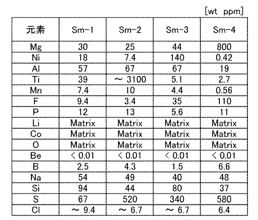


上述の表より、コバルト酸リチウム(材料Sm−1、材料Sm−2、材料Sm−3、材料Sm−4)が有する各元素の濃度範囲を読み取ることができる。たとえばステップS114に用いられるコバルト酸リチウムとして、材料Sm−1を用いる場合、上述の表より、マグネシウム濃度が40wt ppm以下、チタン濃度が40wt ppm以下が好ましいと読み取れる。
<ステップS115>
次に、図17に示すステップS115として、コバルト酸リチウムを加熱する。コバルト酸リチウムに対する最初の加熱のため、ステップS115の加熱を初期加熱と呼ぶことがある。又は以下に示すステップS120の前に加熱するものであるため、予備加熱又は前処理と呼ぶことがある。本ステップに用いる容器及び/又は蓋等は、ステップS113で用いるものと同様である。初期加熱により次の効果が期待されるが、本発明の一態様である正極活物質を得るために初期加熱は必須ではない。
次に、図17に示すステップS115として、コバルト酸リチウムを加熱する。コバルト酸リチウムに対する最初の加熱のため、ステップS115の加熱を初期加熱と呼ぶことがある。又は以下に示すステップS120の前に加熱するものであるため、予備加熱又は前処理と呼ぶことがある。本ステップに用いる容器及び/又は蓋等は、ステップS113で用いるものと同様である。初期加熱により次の効果が期待されるが、本発明の一態様である正極活物質を得るために初期加熱は必須ではない。
初期加熱により、上述したようにコバルト酸リチウムの表層部20aの一部からリチウムが脱離する。また内部20bの結晶性を高める効果が期待できる。またステップS111等で準備したリチウム源及び/又はコバルト源には、不純物が混入していることがある。ステップS114で完成したコバルト酸リチウムから不純物を低減させることが、初期加熱によって可能である。
さらに初期加熱を経ることで、コバルト酸リチウムの表面がなめらかになる効果がある。表面がなめらかとは、凹凸が少なく、複合酸化物が全体的に丸みを帯び、さらに角部が丸みを帯びる様子をいう。さらに、表面へ付着した異物が少ない状態をなめらかと呼ぶ。異物は凹凸の要因となると考えられ、表面へ付着しない方が好ましい。
この初期加熱には、リチウム源を用意しなくてよい。又は、添加元素源を用意しなくてよい。又は、融剤として機能する材料を用意しなくてよい。
本工程の加熱時間は短すぎると十分な効果が得られないが、長すぎると生産性が低下する。例えばステップS113で説明した加熱条件から選択して実施することができる。当該加熱条件に補足すると、本工程の加熱温度は、コバルト酸リチウムの結晶構造を維持するため、ステップS113の温度より低くすると好ましい。また本工程の加熱時間は、コバルト酸リチウムの結晶構造を維持するため、ステップS113の時間より短くすると好ましい。例えば700℃以上1000℃以下の温度で、2時間以上20時間以下の加熱を行うとよい。
また内部20bの結晶性を高める効果とは、例えばステップS113で作製したコバルト酸リチウムが有する収縮差等に由来する歪み、ずれ等を緩和する効果である。
コバルト酸リチウムは、ステップS113の加熱によって、コバルト酸リチウムの表面と内部に温度差が生じることがある。温度差が生じると収縮差が誘発されることがある。温度差により、表面と内部の流動性が異なるため、収縮差が生じうる。収縮差に関連するエネルギーは、コバルト酸リチウムに内部応力の差を与えてしまう。内部応力の差は歪みとも称され、当該エネルギーを歪みエネルギーと呼ぶことがある。内部応力はステップS115の初期加熱により除去され、別言すると歪みエネルギーはステップS115の初期加熱により均質化されうる。歪みエネルギーが均質化されると、コバルト酸リチウムの歪みが緩和される。これに伴い、コバルト酸リチウムの表面がなめらかになる可能性がある。表面が改善されたとも称する。別言すると、ステップS115を経ると、コバルト酸リチウムに生じた収縮差が緩和され、コバルト酸リチウムの表面がなめらかになるため好ましい。
また収縮差は上記コバルト酸リチウムにミクロなずれ、例えば結晶のずれを生じさせることがある。当該ずれを低減するためにも、本工程を実施すると好ましい。本工程を経ると、上記複合酸化物のずれを均一化させることが可能である。ずれが均一化されると、コバルト酸リチウムの表面がなめらかになる可能性がある。結晶粒の整列が行われたとも称する。別言すると、ステップS115を経るとコバルト酸リチウムに生じた結晶等のずれが緩和され、コバルト酸リチウムの表面がなめらかになるため好ましい。
表面がなめらかなコバルト酸リチウムを正極活物質として用いると、二次電池として充放電した際の劣化が少なくなり、正極活物質のクラックを防ぐことができる。
なお、ステップS114として、あらかじめ合成されたコバルト酸リチウムを用いてもよい。この場合、ステップS111乃至ステップS113を省略することができる。あらかじめ合成されたコバルト酸リチウムに対してステップS115を実施することで、表面がなめらかなコバルト酸リチウムを得ることができる。
<ステップS120>
図17に示すステップS120のように、コバルト酸リチウムに添加元素を添加する。具体的には、添加元素を有する化合物(添加元素源と記す)を用意する。本実施の形態で説明する正極活物質の製造方法1では添加元素を複数のステップに分けて加えるため、図17に示すフローにおいて最初に用意する添加元素をA1、2回目に用意する添加元素をA2、3回目に用意する添加元素をA3として区別する。添加元素A1を有する化合物(A1源)は添加元素A2を有する化合物(A2源)と異なる化合物が好ましく、さらにA2源は添加元素A3を有する化合物(A3源)と異なる化合物であると好ましい。添加元素A1を添加するステップS120について、図19Aを用いて詳述する。
図17に示すステップS120のように、コバルト酸リチウムに添加元素を添加する。具体的には、添加元素を有する化合物(添加元素源と記す)を用意する。本実施の形態で説明する正極活物質の製造方法1では添加元素を複数のステップに分けて加えるため、図17に示すフローにおいて最初に用意する添加元素をA1、2回目に用意する添加元素をA2、3回目に用意する添加元素をA3として区別する。添加元素A1を有する化合物(A1源)は添加元素A2を有する化合物(A2源)と異なる化合物が好ましく、さらにA2源は添加元素A3を有する化合物(A3源)と異なる化合物であると好ましい。添加元素A1を添加するステップS120について、図19Aを用いて詳述する。
<ステップS121>
図19Aに示すステップS121では、コバルト酸リチウムに添加するA1源を用意する。A1源と合わせて、リチウム源を準備してもよい。
図19Aに示すステップS121では、コバルト酸リチウムに添加するA1源を用意する。A1源と合わせて、リチウム源を準備してもよい。
添加元素A1としては、マグネシウム、フッ素、ニッケル、アルミニウム、チタン、ジルコニウム、バナジウム、鉄、マンガン、クロム、ニオブ、ヒ素、亜鉛、ケイ素、硫黄、リン及びホウ素から選ばれた一または二以上を用いることができる。
添加元素にマグネシウムを選んだとき、A1源はマグネシウム源(図中Mg源)と呼ぶことができる。当該マグネシウム源としてはマグネシウム化合物を用いることができ、代表的にはフッ化マグネシウム、酸化マグネシウム、水酸化マグネシウム、又は炭酸マグネシウム等を用いることができる。また上述したマグネシウム源を複数用いてもよい。
添加元素にフッ素を選んだとき、A1源はフッ素源(図中F源)と呼ぶことができる。当該フッ素源としてはフッ素化合物を用いることができ、例えばフッ化リチウム(LiF)、フッ化マグネシウム(MgF2)、フッ化アルミニウム(AlF3)、フッ化チタン(TiF4)、フッ化コバルト(CoF2、CoF3)、フッ化ニッケル(NiF2)、フッ化ジルコニウム(ZrF4)、フッ化バナジウム(VF5)、フッ化マンガン、フッ化鉄、フッ化クロム、フッ化ニオブ、フッ化亜鉛(ZnF2)、フッ化カルシウム(CaF2)、フッ化ナトリウム(NaF)、フッ化カリウム(KF)、フッ化バリウム(BaF2)、フッ化セリウム(CeF3、CeF4)、フッ化ランタン(LaF3)、又は六フッ化アルミニウムナトリウム(Na3AlF6)等を用いることができる。なかでも、フッ化リチウムは融点が848℃と比較的低く、後述する加熱工程で溶融しやすいため好ましい。
フッ化マグネシウムはフッ素源としてもマグネシウム源としても用いることができる。またフッ化リチウムはリチウム源としても用いることができる。ステップS121に用いられるその他のリチウム源は炭酸リチウムがある。
またフッ素源は気体であると好ましく、フッ素(F2)、フッ化炭素、フッ化硫黄、又はフッ化酸素(OF2、O2F2、O3F2、O4F2、O5F2、O6F2、O2F)、三フッ化窒素(NF3)等を用い、気体を加熱雰囲気中に混合させてもよい。また気体として上述したフッ素源を複数用いてもよい。
図19Aで説明する製造方法1では、添加元素A1としてマグネシウム及びフッ素を用いることとし、フッ素源にはフッ化リチウム(LiF)を用意し、マグネシウム源にはフッ化マグネシウム(MgF2)を用意する。なおフッ化マグネシウムはマグネシウム源と呼ぶ。
<ステップS122>
次に、図19Aに示すステップS122では、マグネシウム源及びフッ素源を粉砕及び混合する。本工程は、ステップS112で説明した粉砕及び混合の条件から選択して実施することができる。フッ化リチウムとフッ化マグネシウムは、LiF:MgF2=65:35(モル比)程度で混合すると融点を下げる効果が最も高くなる。一方、フッ化リチウムが多くなると、リチウムが過剰になりすぎ、充放電サイクル特性が悪化する懸念がある。そのため、フッ化リチウムとフッ化マグネシウムのモル比は、LiF:MgF2=x:1(0≦x≦1.9)であることが好ましく、LiF:MgF2=x:1(0.1≦x≦0.5)がより好ましく、LiF:MgF2=x:1(x=0.33またはその近傍)がさらに好ましい。なお本明細書等において近傍とは、その値の0.9倍より大きく1.1倍より小さい値とする。
次に、図19Aに示すステップS122では、マグネシウム源及びフッ素源を粉砕及び混合する。本工程は、ステップS112で説明した粉砕及び混合の条件から選択して実施することができる。フッ化リチウムとフッ化マグネシウムは、LiF:MgF2=65:35(モル比)程度で混合すると融点を下げる効果が最も高くなる。一方、フッ化リチウムが多くなると、リチウムが過剰になりすぎ、充放電サイクル特性が悪化する懸念がある。そのため、フッ化リチウムとフッ化マグネシウムのモル比は、LiF:MgF2=x:1(0≦x≦1.9)であることが好ましく、LiF:MgF2=x:1(0.1≦x≦0.5)がより好ましく、LiF:MgF2=x:1(x=0.33またはその近傍)がさらに好ましい。なお本明細書等において近傍とは、その値の0.9倍より大きく1.1倍より小さい値とする。
<ステップS123>
図19Aに示すステップS123では、上記で粉砕、混合した材料を回収して、A1源を得る。回収の際、必要に応じてふるいを実施してもよい。なお、ステップS123に示すA1源は、複数の出発材料を有するものであり、混合物と呼ぶことができる。
図19Aに示すステップS123では、上記で粉砕、混合した材料を回収して、A1源を得る。回収の際、必要に応じてふるいを実施してもよい。なお、ステップS123に示すA1源は、複数の出発材料を有するものであり、混合物と呼ぶことができる。
上記混合物の粒子径又はメディアン径(D50)が600nm以上10μm以下であることが好ましく、1μm以上5μm以下であることがより好ましい。A1源として、一種の材料を用いた場合においても、粒子径又はメディアン径(D50)が600nm以上10μm以下であることが好ましく、1μm以上5μm以下であることがより好ましい。
このような微粉化された混合物(添加元素が1種の場合も含む)であると、後の工程でコバルト酸リチウムと混合したときに、コバルト酸リチウムの粒子の表面に混合物を均一に付着させやすい。コバルト酸リチウムの粒子の表面に混合物が均一に付着していると、加熱後に正極活物質の表層部に均一に添加元素を拡散又は分布させやすいため好ましい。
<ステップS131>
図17に示すステップS131では、コバルト酸リチウムと、A1源とを混合する。コバルト酸リチウム中のコバルトの原子数Coと、A1源が有するマグネシウムの原子数Mgとの比は、Co:Mg=100:y(0.1≦y≦3)であることが好ましく、Co:Mg=100:y(0.3≦y≦1)であることがより好ましい。
図17に示すステップS131では、コバルト酸リチウムと、A1源とを混合する。コバルト酸リチウム中のコバルトの原子数Coと、A1源が有するマグネシウムの原子数Mgとの比は、Co:Mg=100:y(0.1≦y≦3)であることが好ましく、Co:Mg=100:y(0.3≦y≦1)であることがより好ましい。
ステップS131の混合には、機械的エネルギーによる複合化処理を適用することができる。複合化処理とは、ロータ等を用いて粉体層に機械エネルギー(衝撃、圧縮、又はせん断に関するエネルギー)を与えて、メカノケミカル反応を起こし、新たな素材とさせるような処理である。複合化処理におけるロータの回転数は2000rpm以上4000rpm以下が好ましく、処理時間は5分以上30分以下が好ましい。また回転により熱を生じることがあるため、複合化処理装置は水冷機能を加えてもよい。
またステップS131の混合には、ボールミル又はビーズミル等を用いることができる。コバルト酸リチウムの粒子の形状を破壊させないためにステップS112の混合よりも穏やかな条件とすることが好ましい。例えば、ステップS112の混合よりも回転数が少ない、または時間が短い条件とすることが好ましい。また湿式よりも乾式のほうが穏やかな条件であると言える。
<ステップS132>
図17のステップS132において、上記で混合した材料を回収し、混合物901を得る。回収の際、必要に応じてふるいを実施してもよい。
図17のステップS132において、上記で混合した材料を回収し、混合物901を得る。回収の際、必要に応じてふるいを実施してもよい。
<ステップS133>
図17に示すステップS133では、混合物901を加熱する。ステップS113で説明した加熱条件から選択して実施することができる。
図17に示すステップS133では、混合物901を加熱する。ステップS113で説明した加熱条件から選択して実施することができる。
ここで加熱温度について補足する。ステップS133の加熱温度の下限は、コバルト酸リチウムと添加元素源との反応が進む温度以上である必要がある。反応が進む温度とは、コバルト酸リチウムと添加元素源との有する元素の相互拡散が起きる温度が好ましく、これらの材料の溶融温度よりも低くてもよい。酸化物を例にして説明するが、溶融温度Tmの0.757倍(タンマン温度Td)から固相拡散が起こることがわかっている。そのため、ステップS133における加熱温度としては、650℃以上が好ましい。
勿論、混合物901が有する材料から選ばれた一または二以上が溶融する温度以上であると、より反応が進みやすい。LiF及びMgF2を有する場合、LiFとMgF2の共融点は742℃付近であるため、ステップS133の加熱温度は742℃以上とすると好ましい。フッ化リチウムをはじめとするフッ化物の融点が、他の添加元素源の融点より低い場合、その他の添加元素源の融点を下げる融剤(フラックス剤ともいう)として機能しうる。例えば、添加元素源として、LiF及びMgF2を有する場合、LiFとMgF2の共融点は742℃付近であるため、ステップS133の加熱温度は742℃以上とすると好ましい。
また、LiCoO2:LiF:MgF2=100:0.33:1(モル比)となるように混合して得られた混合物903は、示差走査熱量測定(DSC測定)において初期融解温度Timは779℃、融解ピーク温度Tpmは815℃、融解終了温度Temは826℃であった。よって、加熱温度は826℃以上とすると好ましい。
加熱温度はコバルト酸リチウムの融点(1130℃)未満とする。なお融点近傍の温度では、微量ではあるがコバルト酸リチウムの融解が懸念される。さらに混合物903を加熱する際、フッ素源等に起因するフッ素またはフッ化物の分圧を適切な範囲に制御することが好ましい。温度が高すぎると、フッ化物が昇華により減少する。たとえばフッ化リチウムの蒸気圧は900℃から急激に上昇する。そのため、加熱温度は1000℃以下であるとより好ましく、950℃以下であるとさらに好ましく、900℃以下であるとさらに好ましく、850℃以下であるとさらに好ましい。フッ化リチウムの昇華が抑制されると、正極活物質の表層部において、適切な濃度のフッ素及びリチウムを有することができる。さらに表層部が十分なリチウムを有すると、添加元素としてチタンを添加した際に異相(MgTiO3等)を生成しにくくなる利点もある。
これらを踏まえると、ステップS133における加熱温度としては、650℃以上1130℃以下が好ましく、650℃以上1000℃以下がより好ましく、650℃以上950℃以下がさらに好ましく、650℃以上900℃以下がさらに好ましい。また、742℃以上1130℃以下が好ましく、742℃以上1000℃以下がより好ましく、742℃以上950℃以下がさらに好ましく、742℃以上900℃以下がさらに好ましい。また、826℃以上1100℃以下が好ましく、826℃以上1130℃以下が好ましく、826℃以上1000℃以下がより好ましく、826℃以上950℃以下がさらに好ましく、826℃以上900℃以下がさらに好ましい。なおステップS133における加熱温度は、ステップS113よりも低いとよい。
なお製造方法1では、例えばフッ素源であるLiFが融剤として機能する場合がある。この機能により加熱温度を例えば742℃以上950℃以下とすることができ生産性が向上する。しかし、LiFは酸素よりも気体状態での比重が軽いため、加熱によりLiFが昇華する可能性があり、昇華すると混合物903中のLiFが減少してしまう。すると融剤としての機能が弱くなってしまう。よって、LiFの昇華を抑制しつつ、加熱する必要がある。なお、フッ素源としてLiFを用いなかったとしても、コバルト酸リチウムの表面のLiとフッ素源のFが反応してLiFが生じ、当該LiFが昇華する可能性もある。そのため、LiFでないフッ素源を用いたとしても、同じように昇華の抑制が必要である。
そこで、たとえば混合物を収容する容器に蓋を配置することで、LiFを含む雰囲気で混合物901を加熱することが好ましい。混合物901中のLiFの昇華を抑制することができる。
また加熱時の炉は酸素を有する雰囲気とする。酸素が不足すると、コバルト等が還元され、コバルト酸リチウムが層状岩塩型の結晶構造を保てなくなるおそれがある。例えば炉内は大気圧を超えた圧力としてもよい。
本ステップは、混合物901の粒子同士が固着しないように加熱すると好ましい。加熱中に混合物901粒子同士が固着すると、添加元素(例えばフッ素)が拡散する経路を阻害することとなり、表層部への添加元素(例えばマグネシウム及びフッ素)の分布が悪化する可能性がある。さらに粒子同士の固着は、酸素との接触面積が減る恐れもある。
ロータリーキルンによって加熱する場合は、炉内の酸素を含む雰囲気の流量を制御して加熱することが好ましい。また最初に雰囲気をパージし炉内に酸素雰囲気を導入した後は雰囲気のフローはしない。ローラーハースキルンによって加熱する場合は、例えば混合物901の入った容器に蓋を配置することでLiFを含む雰囲気で混合物901を加熱することができる。
加熱温度は高い方が反応が進みやすく、加熱時間が短く済み、生産性が高く好ましい。加熱時間は2時間以上が好ましく、5時間以上20時間以下がより好ましい。
加熱条件について補足する。加熱時間は、加熱温度、ステップS133のコバルト酸リチウムの粒子径又はメディアン径(D50)、及び組成等の条件により変化する。コバルト酸リチウムの粒子径又はメディアン径(D50)が小さい場合は、それが大きい場合よりも低い温度または短い時間がより好ましい場合がある。図17のステップS133のコバルト酸リチウムの粒子径又はメディアン径(D50)が7μm程度の場合、加熱温度は例えば650℃以上950℃以下が好ましく、750℃以上950℃以下がより好ましい。加熱時間は例えば5時間以上20時間以下が好ましく、8時間以上12時間以下がより好ましい。
<ステップS134>
図17に示すステップS134では、加熱した材料を回収し、複合酸化物902を得る。本ステップにおいて、回収の後、必要に応じて解砕してもよい。
図17に示すステップS134では、加熱した材料を回収し、複合酸化物902を得る。本ステップにおいて、回収の後、必要に応じて解砕してもよい。
<ステップS140>
図17に示すステップS140では、A2源を用意する。添加元素A2としては、ステップS121で説明した添加元素を用いることができ、添加元素A2は添加元素A1と異なる元素を選択すると好ましい。製造方法1では、添加元素A2としてニッケル及びアルミニウムを用いることとする。ニッケル源としてはニッケル化合物を用いることができ、代表的には酸化ニッケル、水酸化ニッケル等を用いることができる。アルミニウム源としてはアルミニウム化合物を用いることができ、代表的には酸化アルミニウム、水酸化アルミニウム、等を用いることができる。添加元素A2を添加するステップS140について、図19Bを用いて詳述する。
図17に示すステップS140では、A2源を用意する。添加元素A2としては、ステップS121で説明した添加元素を用いることができ、添加元素A2は添加元素A1と異なる元素を選択すると好ましい。製造方法1では、添加元素A2としてニッケル及びアルミニウムを用いることとする。ニッケル源としてはニッケル化合物を用いることができ、代表的には酸化ニッケル、水酸化ニッケル等を用いることができる。アルミニウム源としてはアルミニウム化合物を用いることができ、代表的には酸化アルミニウム、水酸化アルミニウム、等を用いることができる。添加元素A2を添加するステップS140について、図19Bを用いて詳述する。
<ステップS141乃至ステップS143>
図19BのステップS141では、ニッケル源(図中Ni源)及びアルミニウム源(図中Al源)を用意する。コバルト酸リチウム中のコバルトの原子数Coと、A2源が有するニッケルの原子数Niとの比は、Co:Ni=100:z1(0.2≦z1≦0.7)であることが好ましく、Co:Ni=100:z1(0.4≦z1≦0.6)であることがより好ましい。コバルト酸リチウム中のコバルトの原子数Coと、A2源が有するアルミニウムの原子数Alとの比は、Co:Al=100:z2(0.1≦z2≦0.5)であることが好ましく、Co:Al=100:z2(0.15≦z2≦0.3)であることがより好ましい。さらに述べると本ステップにおいて、アルミニウムの添加濃度はニッケルの添加濃度より低くすると好ましい。
図19BのステップS141では、ニッケル源(図中Ni源)及びアルミニウム源(図中Al源)を用意する。コバルト酸リチウム中のコバルトの原子数Coと、A2源が有するニッケルの原子数Niとの比は、Co:Ni=100:z1(0.2≦z1≦0.7)であることが好ましく、Co:Ni=100:z1(0.4≦z1≦0.6)であることがより好ましい。コバルト酸リチウム中のコバルトの原子数Coと、A2源が有するアルミニウムの原子数Alとの比は、Co:Al=100:z2(0.1≦z2≦0.5)であることが好ましく、Co:Al=100:z2(0.15≦z2≦0.3)であることがより好ましい。さらに述べると本ステップにおいて、アルミニウムの添加濃度はニッケルの添加濃度より低くすると好ましい。
次にステップS142では、ニッケル源及びアルミニウム源をそれぞれ粉砕する。粉砕の条件はステップS122の条件を参照することができる。その後ステップS143では、上記で粉砕した材料を混合して、A2源を得る。
<ステップS151>
図17に示すステップS151では、複合酸化物902と、A2源とを混合する。混合条件はステップS131の記載を参照することができる。
図17に示すステップS151では、複合酸化物902と、A2源とを混合する。混合条件はステップS131の記載を参照することができる。
<ステップS152>
次に図17に示すステップS152おいて、上記で混合した材料を回収し、混合物903を得る。回収の際、ふるいを実施してもよい。
次に図17に示すステップS152おいて、上記で混合した材料を回収し、混合物903を得る。回収の際、ふるいを実施してもよい。
<ステップS153>
次に図17に示すステップS153では、混合物903を加熱する。加熱条件はステップS133の記載を参照することができる。なお本ステップでも混合物を収容する容器に蓋を配置すると好ましい。また本ステップにおいて加熱時間について補足する。加熱時間が短いと生産性が高く好ましい。本ステップの加熱時間はステップS133よりも短くすることができる。具体的には、1時間以上が好ましく、1時間以上5時間以下がより好ましい。
次に図17に示すステップS153では、混合物903を加熱する。加熱条件はステップS133の記載を参照することができる。なお本ステップでも混合物を収容する容器に蓋を配置すると好ましい。また本ステップにおいて加熱時間について補足する。加熱時間が短いと生産性が高く好ましい。本ステップの加熱時間はステップS133よりも短くすることができる。具体的には、1時間以上が好ましく、1時間以上5時間以下がより好ましい。
<ステップS154>
図17に示すステップS154では、加熱した材料を回収し、正極活物質21を得る。本ステップにおいて、回収の後、必要に応じて解砕してもよい。回収の際、ふるいを実施してもよい。以上のような製造方法1により、本発明の一態様の正極活物質を製造することができる。製造方法1は生産性の高い方法であり、コストを抑えた製造方法を提供することができる。
図17に示すステップS154では、加熱した材料を回収し、正極活物質21を得る。本ステップにおいて、回収の後、必要に応じて解砕してもよい。回収の際、ふるいを実施してもよい。以上のような製造方法1により、本発明の一態様の正極活物質を製造することができる。製造方法1は生産性の高い方法であり、コストを抑えた製造方法を提供することができる。
《正極活物質の製造方法2》
本発明を実施する一形態であって、製造方法1とは異なる正極活物質21の製造方法2について、図18を用いて説明する。製造方法2は主に添加元素を加える回数が製造方法1と異なり、その他の記載は製造方法1の記載を参照することができる。
本発明を実施する一形態であって、製造方法1とは異なる正極活物質21の製造方法2について、図18を用いて説明する。製造方法2は主に添加元素を加える回数が製造方法1と異なり、その他の記載は製造方法1の記載を参照することができる。
製造方法1と同様にステップS154まで実施する。ただしステップS115の加熱処理は実施しなくともよい。
<ステップS160>
図18に示すステップS160では、A3源を用意する。添加元素A3としては、ステップS121で説明した添加元素を用いることができ、添加元素A3は添加元素A1及び添加元素A2と異なる元素を選択すると好ましい。製造方法1では、添加元素A3としてチタンを用いることとする。チタン源には、チタンを有する化合物(チタン化合物)を用いるが、チタン化合物にはチタン酸化物、チタン酸リチウム等が挙げられる。チタン酸化物にはTiO2で示される化合物があり、チタン酸リチウムにはLi2TiO3、LiTiO2で示される化合物がある。チタン源として上述した化合物から選ばれた一又は二以上を用いることができる。添加元素A3を添加するステップS160について、図19Cを用いて詳述する。
図18に示すステップS160では、A3源を用意する。添加元素A3としては、ステップS121で説明した添加元素を用いることができ、添加元素A3は添加元素A1及び添加元素A2と異なる元素を選択すると好ましい。製造方法1では、添加元素A3としてチタンを用いることとする。チタン源には、チタンを有する化合物(チタン化合物)を用いるが、チタン化合物にはチタン酸化物、チタン酸リチウム等が挙げられる。チタン酸化物にはTiO2で示される化合物があり、チタン酸リチウムにはLi2TiO3、LiTiO2で示される化合物がある。チタン源として上述した化合物から選ばれた一又は二以上を用いることができる。添加元素A3を添加するステップS160について、図19Cを用いて詳述する。
<ステップS161乃至ステップS163>
図19CのステップS160では、チタン源(図中Ti源)を用意する。コバルト酸リチウム中のコバルトの原子数Coと、A3源が有するチタンの原子数Tiとの比は、Co:Ti=100:z3(0.01≦z3≦0.5)であることが好ましく、Co:Ti=100:z3(0.05≦z3≦0.25)であることがより好ましい。
図19CのステップS160では、チタン源(図中Ti源)を用意する。コバルト酸リチウム中のコバルトの原子数Coと、A3源が有するチタンの原子数Tiとの比は、Co:Ti=100:z3(0.01≦z3≦0.5)であることが好ましく、Co:Ti=100:z3(0.05≦z3≦0.25)であることがより好ましい。
次にステップS162では、チタン源を粉砕する。粉砕の条件はステップS122の条件を参照することができる。その後ステップS163では、上記で粉砕した材料を回収して、A3源を得る。
<ステップS171>
図16に示すステップS171では、複合酸化物904と、A3源とを混合する。混合条件はステップS131の記載を参照することができる。
図16に示すステップS171では、複合酸化物904と、A3源とを混合する。混合条件はステップS131の記載を参照することができる。
<ステップS172>
次に図18に示すステップS172おいて、上記で混合した材料を回収し、混合物905を得る。回収の際、ふるいを実施してもよい。
次に図18に示すステップS172おいて、上記で混合した材料を回収し、混合物905を得る。回収の際、ふるいを実施してもよい。
<ステップS173>
図18に示すステップS173では、混合物905を加熱する。加熱条件はステップS133の記載を参照することができる。なお本ステップでも混合物を収容する容器に蓋を配置すると好ましい。また本ステップにおいて加熱時間について補足する。加熱時間が短いと生産性が高く好ましい。本ステップの加熱時間はステップS133よりも短くすることができる。具体的には、1時間以上が好ましく、1時間以上5時間以下がより好ましい。
図18に示すステップS173では、混合物905を加熱する。加熱条件はステップS133の記載を参照することができる。なお本ステップでも混合物を収容する容器に蓋を配置すると好ましい。また本ステップにおいて加熱時間について補足する。加熱時間が短いと生産性が高く好ましい。本ステップの加熱時間はステップS133よりも短くすることができる。具体的には、1時間以上が好ましく、1時間以上5時間以下がより好ましい。
<ステップS174>
図18に示すステップS174では、加熱した材料を回収し、正極活物質21を得る。回収の際、ふるいを実施してもよい。以上のような製造方法1により、本発明の一態様の正極活物質を製造することができる。製造方法1は生産性の高い方法であり、コストを抑えた製造方法を提供することができる。
図18に示すステップS174では、加熱した材料を回収し、正極活物質21を得る。回収の際、ふるいを実施してもよい。以上のような製造方法1により、本発明の一態様の正極活物質を製造することができる。製造方法1は生産性の高い方法であり、コストを抑えた製造方法を提供することができる。
《正極活物質の製造方法3》
本発明を実施する一形態であって、製造方法1及び2とは異なる正極活物質21の製造方法3について、図20A及び図20Bを用いて説明する。製造方法3は主に添加元素を加える回数が製造方法1と異なり、その他の記載は製造方法1の記載を参照することができる。
本発明を実施する一形態であって、製造方法1及び2とは異なる正極活物質21の製造方法3について、図20A及び図20Bを用いて説明する。製造方法3は主に添加元素を加える回数が製造方法1と異なり、その他の記載は製造方法1の記載を参照することができる。
製造方法2では添加元素A1としてマグネシウム及びフッ素、添加元素A2としてニッケル及びアルミニウムとして、異なるタイミングで添加させたが、マグネシウム、フッ素、ニッケル及びアルミニウムを同じステップで添加してもよい。図20A及び図20BのステップS120aのA1+A2源として、これらを同じステップで添加する方法を示す。この製造方法も、混合及び加熱工程を減らすことができるため生産性が高い方法であるといえ、コストを抑えた製造方法を提供することができる。
《正極活物質の製造方法4》
本発明を実施する一形態であって、製造方法1乃至3とは異なる正極活物質21の製造方法4について説明する。正極活物質の製造方法4はステップS110において、リチウム源及びコバルト源に加えて、添加元素源(A0源)を用意する。製造方法4では、マグネシウム、フッ素、ニッケル及びアルミニウムを同じステップで添加させたが、これらのうち、マグネシウム源及びフッ素源をA0源として、リチウム源及びコバルト源と同じステップで用意する。この製造方法も、混合及び加熱工程を減らすことができるため生産性が高い方法であるといえ、コストを抑えた製造方法を提供することができる。
本発明を実施する一形態であって、製造方法1乃至3とは異なる正極活物質21の製造方法4について説明する。正極活物質の製造方法4はステップS110において、リチウム源及びコバルト源に加えて、添加元素源(A0源)を用意する。製造方法4では、マグネシウム、フッ素、ニッケル及びアルミニウムを同じステップで添加させたが、これらのうち、マグネシウム源及びフッ素源をA0源として、リチウム源及びコバルト源と同じステップで用意する。この製造方法も、混合及び加熱工程を減らすことができるため生産性が高い方法であるといえ、コストを抑えた製造方法を提供することができる。
なお、A0源がリチウム源及びコバルト源と同じステップで添加されたものとして、あらかじめ合成された、マグネシウム及びフッ素を有するコバルト酸リチウムを用いてもよい。この場合、ステップS111乃至ステップS113を省略することができる。
《正極活物質の製造方法5》
本発明を実施する一形態であって、製造方法1乃至4とは異なる正極活物質21の製造方法4について説明する。製造方法5は、A1源を添加した後に、A2源+A3源としてアルミニウム源、ニッケル源及びチタン源等を添加する方法である。この製造方法も、混合及び加熱工程を減らすことができるため生産性が高い方法であるといえ、コストを抑えた製造方法を提供することができる。
本発明を実施する一形態であって、製造方法1乃至4とは異なる正極活物質21の製造方法4について説明する。製造方法5は、A1源を添加した後に、A2源+A3源としてアルミニウム源、ニッケル源及びチタン源等を添加する方法である。この製造方法も、混合及び加熱工程を減らすことができるため生産性が高い方法であるといえ、コストを抑えた製造方法を提供することができる。
A3源としてチタン化合物を用いるが、少なくともA1源が先に添加された状態でA3源を添加する、又はA1源及びA2源が先に添加された状態で、A3源を添加する順序が、充放電サイクルにおける放電容量の低下を抑制するには好ましいステップである。
製造方法1乃至5は適宜組み合わせることができる。
また本実施の形態は、他の実施の形態と組み合わせて用いることができる。
(実施の形態5)
本実施の形態では、二次電池の形態例について説明する。
本実施の形態では、二次電池の形態例について説明する。
[コイン型二次電池]
コイン型二次電池の一例について説明する。図21Aはコイン型(単層偏平型)の二次電池の分解斜視図であり、図21Bは、外観図であり、図21Cは、その断面図である。コイン型二次電池は主に小型の電子機器に用いられる。本明細書等において、コイン型二次電池は、ボタン型二次電池を含む。
コイン型二次電池の一例について説明する。図21Aはコイン型(単層偏平型)の二次電池の分解斜視図であり、図21Bは、外観図であり、図21Cは、その断面図である。コイン型二次電池は主に小型の電子機器に用いられる。本明細書等において、コイン型二次電池は、ボタン型二次電池を含む。
図21Aでは、わかりやすくするために部材の重なり(上下関係、及び位置関係)がわかるように模式図としている。従って図21Aと図21Bは完全に一致する対応図とはしていない。
図21Aでは、正極304、負極307、スペーサ342、ワッシャー332が重なり、負極缶302、正極缶301で封止する様子を示す。なお図21Aでは、上記実施の形態で説明した電解質及びセパレータは図示しない。スペーサ342、及びワッシャー332は、正極缶301と負極缶302を圧着する際に、内部を保護又は缶内の位置を固定するために用いられている。スペーサ342、又はワッシャー332はステンレス又は絶縁材料を用いる。
正極集電体305上に正極活物質層306が形成された積層構造を正極304としている。
図21Bは、完成したコイン型二次電池300の斜視図である。
コイン型二次電池300は、正極端子を兼ねた正極缶301と負極端子を兼ねた負極缶302とが、ポリプロピレン等で形成されたガスケット303で絶縁シールされていてもよい。正極304は、正極集電体305と、これと接するように設けられた正極活物質層306により形成される。また、負極307は、負極集電体308と、これに接するように設けられた負極活物質層309により形成される。正極缶301は正極304と、負極缶302は負極307とそれぞれ電気的に接続される。
なお、コイン型二次電池300に用いる正極304及び負極307は、それぞれ活物質層は片面のみに形成すると好ましい。
図21Cに示すように、正極缶301を下にして正極304、負極307、負極缶302をこの順で積層し、正極缶301と負極缶302とをガスケット303を介して圧着してコイン型二次電池300を製造する。
コイン型二次電池300に、本発明の二次電池を用いることで、安全性の高い二次電池となる。
[円筒型二次電池]
円筒型二次電池の例について図22Aを参照して説明する。円筒型の二次電池616は、図22Aに示すように、上面に正極キャップ(電池蓋)601を有し、側面及び底面に電池缶(外装缶)602を有している。これら正極キャップ601と電池缶(外装缶)602とは、ガスケット(絶縁パッキン)610によって絶縁されている。
円筒型二次電池の例について図22Aを参照して説明する。円筒型の二次電池616は、図22Aに示すように、上面に正極キャップ(電池蓋)601を有し、側面及び底面に電池缶(外装缶)602を有している。これら正極キャップ601と電池缶(外装缶)602とは、ガスケット(絶縁パッキン)610によって絶縁されている。
図22Bは、円筒型二次電池の断面を模式的に示した図である。図22Bに示す円筒型二次電池は、上面に正極キャップ(電池蓋)601を有し、側面及び底面に電池缶(外装缶)602を有している。これら正極キャップと電池缶(外装缶)602とは、ガスケット(絶縁パッキン)610によって絶縁されている。
中空円柱状の電池缶602の内側には、帯状の正極604と負極606とが電解質層605を間に挟んで捲回された電池素子が設けられている。図示しないが、電池素子は中心軸を中心に捲回されている。電池缶602は、一端が閉じられ、他端が開いている。電池缶602の内側において、正極、負極及びセパレータが捲回された電池素子は、対向する一対の絶縁板608、絶縁板609により挟まれている。また、電池素子が設けられた電池缶602の内部は、本発明の一態様の電解質(図示せず)が注入されている。
円筒型の蓄電池に用いる正極及び負極は捲回するため、集電体の両面に活物質を形成することが好ましい。なお図22A乃至図22Dでは円筒の直径よりも円筒の高さの方が大きい二次電池616を図示したが、これに限らない。円筒の直径が、円筒の高さよりも大きい二次電池としてもよい。このような構成により、例えば二次電池の小型化を図ることができる。
正極604には正極端子(正極集電リード)603が接続され、負極606には負極端子(負極集電リード)607が接続される。正極端子603は、アルミニウムなどの金属材料を用いることができる。負極端子607は、銅などの金属材料を用いることができる。正極端子603は安全弁機構613に、負極端子607は電池缶602の底にそれぞれ抵抗溶接される。安全弁機構613は、PTC(Positive Temperature Coefficient)素子611を介して正極キャップ601と電気的に接続されている。安全弁機構613は電池の内圧の上昇が所定の閾値を超えた場合に、正極キャップ601と正極604との電気的な接続を切断するものである。また、PTC素子611は温度が上昇した場合に抵抗が増大する熱感抵抗素子であり、抵抗の増大により電流量を制限して異常発熱を防止するものである。PTC素子には、チタン酸バリウム(BaTiO3)系セラミックス材料等を用いることができる。
図22Cは蓄電システム615の一例を示す。蓄電システム615は複数の二次電池616を有し、バッテリーパックと呼ぶこともある。それぞれの二次電池の正極は、絶縁体625で分離された導電体624に接触し、電気的に接続されている。導電体624は配線623を介して、制御回路620に電気的に接続されている。また、それぞれの二次電池の負極は、配線626を介して制御回路620に電気的に接続されている。制御回路620として、過充電又は過放電を防止する保護回路等を適用することができる。
図22Dは、蓄電システム615の一例を示す。蓄電システム615は複数の二次電池616を有し、複数の二次電池616は、導電板628及び導電板614の間に挟まれている。複数の二次電池616は、配線627により導電板628及び導電板614と電気的に接続される。複数の二次電池616は、並列接続されていてもよいし、直列接続されていてもよいし、並列に接続された後さらに直列に接続されていてもよい。複数の二次電池616を有する蓄電システム615を構成することで、大きな電力を取り出すことができる。
複数の二次電池616が、並列に接続された後、さらに直列に接続されてもよい。
複数の二次電池616の間に温度制御装置を有していてもよい。二次電池616が過熱されたときは、温度制御装置により冷却し、二次電池616が冷えすぎているときは温度制御装置により加熱することができる。そのため蓄電システム615の性能が外気温に影響されにくくなる。
また、図22Dにおいて、蓄電システム615は制御回路620に配線621及び配線622を介して電気的に接続されている。配線621は導電板628を介して複数の二次電池616の正極に、配線622は導電板614を介して複数の二次電池616の負極に、それぞれ電気的に接続される。
円筒型の二次電池616に、本発明の二次電池を用いることで、安全性の高い二次電池とすることができる。
[二次電池の他の構造例]
二次電池の構造例について図23及び図24を用いて説明する。
二次電池の構造例について図23及び図24を用いて説明する。
図23Aに示す二次電池913は、筐体930の内部に端子951と端子952が設けられた捲回体950を有する。捲回体950は、筐体930の内部で本発明の一形態の電解質に含浸される。端子952は、筐体930に接し、端子951は、絶縁材などを用いることにより筐体930に接していない。なお、図23Aでは、便宜のため、筐体930を分離して図示しているが、実際は、捲回体950が筐体930に覆われ、端子951及び端子952が筐体930の外に延在している。筐体930としては、金属材料(例えばアルミニウムなど)又は金属材料と樹脂材料との積層体を用いることができる。
なお、図23Bに示すように、図23Aに示す筐体930を複数の材料によって形成してもよい。例えば、図23Bに示す二次電池913は、筐体930aと筐体930bが貼り合わされており、筐体930a及び筐体930bで囲まれた領域に捲回体950が設けられている。
筐体930aとしては、金属材料と樹脂材料との積層体などを用いることができる。特に、アンテナが形成される面に樹脂材料である有機樹脂を形成することにより、二次電池913による電界を抑制できる。なお、筐体930aによる電界の遮蔽が小さければ、筐体930aの内部にアンテナを設けてもよい。筐体930bとしては、例えば金属材料又は金属材料と樹脂材料との積層体を用いることができる。
さらに、捲回体950の構造について図23Cに示す。捲回体950は、負極931と、正極932と、電解質層933と、を有する。捲回体950は、電解質層933を挟んで負極931と、正極932が重なり合って積層され、該積層シートを捲回させた捲回体である。なお、負極931と、正極932と、電解質層933と、の積層を、さらに複数重ねてもよい。
また、図24A乃至図24Cに示すような捲回体950aを有する二次電池913としてもよい。図24Aに示す捲回体950aは、負極931と、正極932と、電解質層933と、を有する。負極931は負極活物質層931aを有する。正極932は正極活物質層932aを有する。
電解質層933は、負極活物質層931a及び正極活物質層932aよりも広い幅を有し、負極活物質層931a及び正極活物質層932aと重畳するように捲回されている。また正極活物質層932aよりも負極活物質層931aの幅が広いことが安全性の点で好ましい。またこのような形状の捲回体950aは安全性及び生産性がよく好ましい。
図24Bに示すように、負極931は端子951と電気的に接続される。端子951は端子911aと電気的に接続される。また正極932は端子952と電気的に接続される。端子952は端子911bと電気的に接続される。
図24Cに示すように、筐体930により捲回体950aが覆われ、二次電池913となる。筐体930には安全弁、過電流保護素子等を設けることが好ましい。安全弁は筐体930の内部が所定の内圧で開放する弁であり、二次電池破裂を防止することができる。
図24Bに示すように二次電池913は複数の捲回体950aを有していてもよい。複数の捲回体950aを用いることで、より充放電容量の大きい二次電池913とすることができる。図24A及び図24Bに示す二次電池913の他の要素は、図23A乃至図23Cに示す二次電池913の記載を参考にすることができる。
捲回体を有する二次電池913に、本発明の二次電池を用いることで、安全性の高い二次電池とすることができる。
本実施の形態の内容は、他の実施の形態の内容と適宜組み合わせることができる。
(実施の形態6)
本実施の形態では、図25A乃至図25Cを用いて電気自動車(EV)に適用する例を示す。
本実施の形態では、図25A乃至図25Cを用いて電気自動車(EV)に適用する例を示す。
図25Aに示すように電気自動車には、メインの駆動用の二次電池として第1のバッテリ1301a、1301bと、モータ1304を始動させるインバータ1312に電力を供給する第2のバッテリ1311が設置されている。第1のバッテリ1301a、1301bに、本発明の二次電池を用いることで、安全性の高い二次電池とすることができる。
第2のバッテリ1311はクランキングバッテリー(スターターバッテリーとも呼ばれる)とも呼ばれる。第2のバッテリ1311は高出力できればよく、大容量はそれほど必要とされず、第2のバッテリ1311の容量は第1のバッテリ1301a、1301bと比較して小さい。
第1のバッテリ1301aの内部構造は、捲回型であってもよいし、積層型であってもよい。また、第1のバッテリ1301aは、全固体電池を用いてもよい。第1のバッテリ1301aに全固体電池を用いることで高容量とすることができ、安全性が向上し、小型化、軽量化することができる。
本実施の形態では、第1のバッテリ1301a、1301bを2つ並列に接続させている例を示しているが3つ以上並列に接続させてもよい。また、第1のバッテリ1301aで十分な電力を貯蔵できるのであれば、第1のバッテリ1301bはなくてもよい。複数の二次電池を有する電池パックを構成することで、大きな電力を取り出すことができる。複数の二次電池は、並列接続されていてもよいし、直列接続されていてもよいし、並列に接続された後、さらに直列に接続されていてもよい。複数の二次電池を組電池とも呼ぶ。
また、車載用の二次電池において、複数の二次電池からの電力を遮断するため、工具を使わずに高電圧を遮断できるサービスプラグ又はサーキットブレーカを有しており、第1のバッテリ1301aに設けられる。
また、第1のバッテリ1301a、1301bの電力は、主にモータ1304を回転させることに使用されるが、DCDC回路1306を介して42V系の車載部品(電動パワステ1307、ヒータ1308、デフォッガ1309など)に電力を供給する。後輪にリアモータ1317を有している場合にも、第1のバッテリ1301aがリアモータ1317を回転させることに使用される。
また、第2のバッテリ1311は、DCDC回路1310を介して14V系の車載部品(オーディオ1313、パワーウィンドウ1314、ランプ類1315など)に電力を供給する。
また、第1のバッテリ1301aについて、図25Bを用いて説明する。
図25Bでは9個の角型二次電池1300を一つの電池パック1415としている例を示している。また、9個の角型二次電池1300を直列接続し、一方の電極を絶縁体からなる固定部1413で固定し、もう一方の電極を絶縁体からなる固定部1414で固定している。本実施の形態では固定部1413、1414で固定する例を示しているが電池収容ボックス(筐体とも呼ぶ)に収納させる構成としてもよい。車両は外部(路面など)から振動又は揺れが加えられることを想定されているため、固定部1413、1414及び電池収容ボックスなどで複数の二次電池を固定することが好ましい。また、一方の電極は配線1421によって制御回路部1320に電気的に接続されている。他方の電極は配線1422によって制御回路部1320に電気的に接続されている。
また、制御回路部1320は、酸化物半導体を用いたトランジスタを含むメモリ回路を用いてもよい。酸化物半導体を用いたトランジスタを含むメモリ回路を有する充電制御回路、又は電池制御システムを、BTOS(Battery operating system、又はBattery oxide semiconductor)と呼称する場合がある。
酸化物半導体として機能する金属酸化物を用いることが好ましい。例えば、酸化物として、In−M−Zn酸化物(元素Mは、アルミニウム、ガリウム、イットリウム、銅、バナジウム、ベリリウム、ホウ素、チタン、鉄、ニッケル、ゲルマニウム、ジルコニウム、モリブデン、ランタン、セリウム、ネオジム、ハフニウム、タンタル、タングステン、又はマグネシウムから選ばれた一種、又は複数種)等の金属酸化物を用いるとよい。特に、酸化物として適用できるIn−M−Zn酸化物は、CAAC−OS(C−Axis Aligned Crystal Oxide Semiconductor)、CAC−OS(Cloud−Aligned Composite Oxide Semiconductor)であることが好ましい。また、酸化物として、In−Ga酸化物、In−Zn酸化物を用いてもよい。CAAC−OSは、複数の結晶領域を有し、当該複数の結晶領域はc軸が特定の方向に配向している酸化物半導体である。なお、特定の方向とは、CAAC−OS膜の厚さ方向、CAAC−OS膜の被形成面の法線方向、又はCAAC−OS膜の表面の法線方向である。また、結晶領域とは、原子配列に周期性を有する領域である。なお、原子配列を格子配列とみなすと、結晶領域とは、格子配列の揃った領域でもある。さらに、CAAC−OSは、AB面方向において複数の結晶領域が連結する領域を有し、当該領域は歪みを有する場合がある。なお、歪みとは、複数の結晶領域が連結する領域において、格子配列の揃った領域と、別の格子配列の揃った領域と、の間で格子配列の向きが変化している箇所を指す。つまり、CAAC−OSは、c軸配向し、AB面方向には明らかな配向をしていない酸化物半導体である。
また、低温環境下で使用可能であるため、制御回路部1320は酸化物半導体を用いるトランジスタを用いることが好ましい。プロセスを簡略なものとするため、制御回路部1320は単極性のトランジスタを用いて形成してもよい。半導体層に酸化物半導体を用いるトランジスタは、動作周囲温度が単結晶Siよりも広く−40℃以上150℃以下であり、二次電池が加熱しても特性変化が単結晶に比べて小さい。酸化物半導体を用いるトランジスタのオフ電流は、150℃であっても温度によらず測定下限以下であるが、単結晶Siトランジスタのオフ電流特性は、温度依存性が大きい。例えば、150℃では、単結晶Siトランジスタはオフ電流が上昇し、電流オン/オフ比が十分に大きくならない。制御回路部1320は、安全性を向上することができる。
酸化物半導体を用いたトランジスタを含むメモリ回路を用いた制御回路部1320は、マイクロショート等の10項目の不安定性の原因に対し、二次電池の自動制御装置として機能させることもできる。10項目の不安定性の原因を解消する機能としては、過充電の防止、過電流の防止、充電時過熱制御、組電池でのセルバランス、過放電の防止、残量計、温度に応じた充電電圧及び電流量自動制御、劣化度に応じた充電電流量制御、マイクロショート異常挙動検知、マイクロショートに関する異常予測などが挙げられ、そのうちの少なくとも一つの機能を制御回路部1320が有する。また、二次電池の自動制御装置の超小型化が可能である。
また、マイクロショートとは内部ショートの一であり、二次電池の内部の微小な短絡のことを指す。マイクロショートの原因の一つは、充放電が複数回行われることによって、正極活物質の不均一な分布により、正極の一部と負極の一部で局所的な電流の集中が生じ、又は副反応による副反応物の発生によりミクロな短絡が生じていると言われている。
また、マイクロショートの検知だけでなく、制御回路部1320は、二次電池の端子電圧を検知し、二次電池の充放電状態を管理するとも言える。例えば、過充電を防ぐために充電回路の出力トランジスタと遮断用スイッチの両方をほぼ同時にオフ状態とすることができる。
また、図25Bに示す電池パック1415のブロック図の一例を図25Cに示す。
制御回路部1320は、少なくとも過充電を防止するスイッチと、過放電を防止するスイッチを含むスイッチ部1324と、スイッチ部1324を制御する制御回路1322と、第1のバッテリ1301aの電圧測定部と、を有する。制御回路部1320は、使用する二次電池の上限電圧と下限電圧が設定されており、外部からの電流上限、及び外部への出力電流の上限などを制限している。二次電池の下限電圧以上上限電圧以下の範囲内は、使用が推奨されている電圧範囲内であり、その範囲外となるとスイッチ部1324が作動し、保護回路として機能する。また、制御回路部1320は、スイッチ部1324を制御して過放電及び過充電を防止するため、保護回路とも呼べる。例えば、過充電となりそうな電圧を制御回路1322で検知した場合にスイッチ部1324のスイッチをオフ状態とすることで電流を遮断する。さらに充放電経路中にPTC素子を設けて温度の上昇に応じて電流を遮断する機能を設けてもよい。また、制御回路部1320は、外部端子1325(+IN)と、外部端子1326(−IN)とを有している。
スイッチ部1324は、nチャネル型のトランジスタ及びpチャネル型のトランジスタを組み合わせて構成することができる。スイッチ部1324は、単結晶シリコンを用いるSiトランジスタを有するスイッチに限定されず、例えば、Ge(ゲルマニウム)、SiGe(シリコンゲルマニウム)、GaAs(ガリウムヒ素)、GaAlAs(ガリウムアルミニウムヒ素)、InP(リン化インジウム)、SiC(シリコンカーバイド)、ZnSe(セレン化亜鉛)、GaN(窒化ガリウム)、GaOx(酸化ガリウム;xは0より大きい実数)などを有するパワートランジスタでスイッチ部1324を形成してもよい。また、OSトランジスタを用いた記憶素子は、Siトランジスタを用いた回路上などに積層することで自由に配置可能であるため、集積化を容易に行うことができる。スイッチ部1324上にOSトランジスタを用いた制御回路部1320を積層し、集積化することで1チップとすることもでき、小型化が可能となる。
第1のバッテリ1301a、1301bは、主に42V系(高電圧系)の車載機器に電力を供給し、第2のバッテリ1311は14V系(低電圧系)の車載機器に電力を供給する。第2のバッテリ1311は鉛蓄電池がコスト上有利のため採用されることが多い。第2のバッテリ1311を二次電池とすることでメンテナンスフリーとするメリットがあるが、長期間の使用、例えば3年以上となると、製造時には判別できない異常発生が生じる恐れがある。特にインバータを起動する第2のバッテリ1311が動作不能となると、第1のバッテリ1301a、1301bに残容量があってもモータが起動できないことがある。第2のバッテリ1311が鉛蓄電池の場合は、第1のバッテリから第2のバッテリに電力を供給し、常に満充電状態を維持するように充電されているため、上記のようなモータが動作できなくなることはない。
本実施の形態では、第1のバッテリ1301aと第2のバッテリ1311の両方に二次電池を用いる一例を示すが、第2のバッテリ1311は鉛蓄電池、全固体電池、又は電気二重層キャパシタを用いてもよい。上述した二次電池に、本発明の二次電池を用いることで、安全性の高い二次電池とすることができる。
また、タイヤ1316の回転による回生エネルギーは、ギア1305を介してモータ1304に送られ、モータコントローラ1303及びバッテリーコントローラ1302から制御回路部1321を介して第2のバッテリ1311に充電される。又はバッテリーコントローラ1302から制御回路部1320を介して第1のバッテリ1301aに充電される。又はバッテリーコントローラ1302から制御回路部1320を介して第1のバッテリ1301bに充電される。回生エネルギーを効率よく充電するためには、第1のバッテリ1301a、1301bが急速充電可能であることが望ましい。
バッテリーコントローラ1302は第1のバッテリ1301a、1301bの充電電圧及び充電電流などを設定することができる。バッテリーコントローラ1302は、用いる二次電池の充電特性に合わせて充電条件を設定し、急速充電することができる。
また、図示していないが、外部の充電器と接続させる場合、充電器のコンセント又は充電器の接続ケーブルは、バッテリーコントローラ1302に電気的に接続される。外部の充電器から供給された電力はバッテリーコントローラ1302を介して第1のバッテリ1301a、1301bに充電する。また、充電器によっては、制御回路が設けられており、バッテリーコントローラ1302の機能を用いない場合もあるが、過充電を防ぐため制御回路部1320を介して第1のバッテリ1301a、1301bを充電することが好ましい。また、接続ケーブル又は充電器の接続ケーブルに制御回路を備えている場合もある。制御回路部1320は、ECU(Electronic Control Unit)と呼ばれることもある。ECUは、電動車両に設けられたCAN(Controller Area Network)に接続される。CANは、車内LANとして用いられるシリアル通信規格の一つである。また、ECUは、マイクロコンピュータを含む。また、ECUは、CPU又はGPUを用いる。
充電スタンドなどに設置されている外部の充電器は、100Vコンセント、200Vコンセント、3相200V且つ50kWなどがある。また、非接触給電方式等により外部の充電設備から電力供給を受けて、充電することもできる。
次に、本発明の一態様である二次電池を車両、代表的には輸送用車両に実装する例について説明する。
また、二次電池を車両に搭載すると、ハイブリッド車(HV)、電気自動車(EV)、又はプラグインハイブリッド車(PHV)等の次世代クリーンエネルギー自動車を実現できる。また、農業機械、電動アシスト自転車を含む原動機付自転車、自動二輪車、電動車椅子、電動カート、小型又は大型船舶、潜水艦、固定翼機及び回転翼機等の航空機、ロケット、人工衛星、宇宙探査機、惑星探査機、宇宙船などの輸送用車両に二次電池を搭載することもできる。
図26A乃至図26Dにおいて、本発明の一態様を用いた輸送用車両を例示する。図26Aに示す自動車2001は、走行のための動力源として電気モータを用いる電気自動車である。又は、走行のための動力源として電気モータとエンジンを適宜選択して用いることが可能なハイブリッド自動車である。二次電池を車両に搭載する場合、上記実施の形態で示した二次電池の一例を一箇所又は複数個所に設置する。車両に搭載する二次電池に、本発明の二次電池を用いることで、安全性の高い二次電池とすることができる。
図26Aに示す自動車2001は、電池パック2200を有し、電池パックは、複数の二次電池が接続された電池モジュールを有する。さらに電池パック2200は、電池モジュールに電気的に接続された充電制御装置を有すると好ましい。
また、自動車2001は、自動車2001が有する二次電池にプラグイン方式及び非接触給電方式等により外部の充電設備から電力供給を受けて、充電することができる。充電に際しては、充電方法及びコネクタの規格等はCHAdeMO(登録商標)又はコンボ等の所定の方式で適宜行えばよい。充電設備は、商用施設に設けられた充電ステーションであると好ましく、また家庭の電源であってもよい。例えば、プラグイン技術によって、外部からの電力供給により自動車2001に搭載された蓄電装置を充電することができる。充電は、ACDCコンバータ等の変換装置を介して、交流電力を直流電力に変換して行うことができる。
また、図示しないが、受電装置を車両に搭載し、地上の送電装置から電力を非接触で供給して充電することもできる。この非接触給電方式の場合には、道路又は外壁に送電装置を組み込むことで、停車中に限らず走行中に充電を行うこともできる。また、この非接触給電の方式を利用して、2台の車両同士で電力の送受電を行ってもよい。さらに、車両の外装部に太陽電池を設け、停車時及び走行時に二次電池の充電を行ってもよい。このような非接触での電力の供給には、電磁誘導方式又は磁界共鳴方式を用いることができる。
図26Bは、輸送用車両の一例として電気により制御するモータを有した大型の輸送車2002を示している。輸送車2002の電池モジュールは、例えば公称電圧3.0V以上5.0V以下の二次電池を4個セルユニットとし、48セルを直列に接続した170Vの最大電圧とする。電池パック2201の二次電池の数などが違う以外は、図26Bと同様な機能を備えているので説明は省略する。電池パック2201の二次電池に、本発明の二次電池を用いることで、安全性の高い二次電池とすることができる。
図26Cは、一例として電気により制御するモータを有した大型の輸送車両2003を示している。輸送車両2003の電池モジュールは、例えば公称電圧3.0V以上5.0V以下の二次電池を百個以上直列に接続した600Vの最大電圧とするまた、電池パック2202の電池モジュールを構成する二次電池の数などが違う以外は、図25Bと同様な機能を備えているので説明は省略する。モジュールが有する二次電池に、本発明の二次電池を用いることで、安全性の高い二次電池とすることができる。
図26Dは、一例として燃料を燃焼するエンジンを有した航空機2004を示している。図26Dに示す航空機2004は、離着陸用の車輪を有しているため、輸送車両の一部とも言え、複数の二次電池を接続させて電池モジュールを構成し、電池モジュールと充電制御装置とを含む電池パック2203を有している。
航空機2004の電池モジュールは、例えば4Vの二次電池を8個直列に接続した32Vの最大電圧とする。電池パック2203の電池モジュールを構成する二次電池の数などが違う以外は、図25Bと同様な機能を備えているので説明は省略する。
本実施の形態の内容は、他の実施の形態の内容と適宜組み合わせることができる。
(実施の形態7)
本実施の形態では、二輪車、自転車等の車両に本発明の一態様である二次電池を搭載する例を示す。
本実施の形態では、二輪車、自転車等の車両に本発明の一態様である二次電池を搭載する例を示す。
図27Aは、本発明の一態様の二次電池を用いた電動自転車の一例である。図27Aに示す電動自転車8700に、本発明の一態様の二次電池を適用することができる。本発明の一態様の二次電池は保護回路を有してもよい。
電動自転車8700は、蓄電装置8702を備える。蓄電装置8702は、運転者をアシストするモータに電気を供給することができる。また、蓄電装置8702は、持ち運びができ、図27Bに自転車から取り外した状態を示している。また、蓄電装置8702は、本発明の一態様の二次電池8701が複数内蔵されており、そのバッテリ残量などを表示部8703で表示できるようにしている。二次電池8701に、本発明の二次電池を用いることで、安全性の高い二次電池とすることができる。
また蓄電装置8702は、二次電池の充電制御又は異常検知が可能な制御回路8704を有する。制御回路8704は、二次電池8701の正極及び負極と電気的に接続されている。二次電池による火災等の事故撲滅に大きく寄与することができる。
図27Cは、本発明の一態様の二次電池を用いた二輪車の一例である。図27Cに示すスクータ8600は、蓄電装置8602、サイドミラー8601、方向指示灯8603を備える。蓄電装置8602は、方向指示灯8603に電気を供給することができる。二次電池に、本発明の二次電池を用いることで、安全性の高い二次電池とすることができる。
図27Cに示すスクータ8600は、座席下収納8604に、蓄電装置8602を収納することができる。蓄電装置8602は、座席下収納8604が小型であっても、座席下収納8604に収納することができる。
本実施の形態の内容は、他の実施の形態内容と適宜組み合わせることができる。
(実施の形態8)
本実施の形態では、本発明の一態様である二次電池を電子機器に実装する例について説明する。二次電池を実装する電子機器として、例えば、テレビジョン装置(テレビ、又はテレビジョン受信機ともいう)、コンピュータ用などのモニタ、デジタルカメラ、デジタルビデオカメラ、デジタルフォトフレーム、携帯電話機(携帯電話、携帯電話装置ともいう)、携帯型ゲーム機、携帯情報端末、音響再生装置、パチンコ機などの大型ゲーム機などが挙げられる。携帯情報端末としてはノート型パーソナルコンピュータ、タブレット型端末、電子書籍端末、携帯電話機などがある。
本実施の形態では、本発明の一態様である二次電池を電子機器に実装する例について説明する。二次電池を実装する電子機器として、例えば、テレビジョン装置(テレビ、又はテレビジョン受信機ともいう)、コンピュータ用などのモニタ、デジタルカメラ、デジタルビデオカメラ、デジタルフォトフレーム、携帯電話機(携帯電話、携帯電話装置ともいう)、携帯型ゲーム機、携帯情報端末、音響再生装置、パチンコ機などの大型ゲーム機などが挙げられる。携帯情報端末としてはノート型パーソナルコンピュータ、タブレット型端末、電子書籍端末、携帯電話機などがある。
図28Aは、携帯電話機の一例を示している。携帯電話機2100は、筐体2101に組み込まれた表示部2102の他、操作ボタン2103、外部接続ポート2104、スピーカ2105、マイク2106などを備えている。なお、携帯電話機2100は、二次電池2107を有している。二次電池に、本発明の二次電池を用いることで、安全性の高い二次電池とすることができる。
携帯電話機2100は、移動電話、電子メール、文章閲覧及び作成、音楽再生、インターネット通信、コンピュータゲームなどの種々のアプリケーションを実行することができる。
操作ボタン2103は、時刻設定のほか、電源のオン、オフ動作、無線通信のオン、オフ動作、マナーモードの実行及び解除、省電力モードの実行及び解除など、様々な機能を持たせることができる。例えば、携帯電話機2100に組み込まれたオペレーティングシステムにより、操作ボタン2103の機能を自由に設定することもできる。
また、携帯電話機2100は、通信規格された近距離無線通信を実行することが可能である。例えば無線通信可能なヘッドセットと相互通信することによって、ハンズフリーで通話することもできる。
また、携帯電話機2100は外部接続ポート2104を備え、他の情報端末とコネクタを介して直接データのやりとりを行うことができる。また外部接続ポート2104を介して充電を行うこともできる。なお、充電動作は外部接続ポート2104を介さずに無線給電により行ってもよい。
携帯電話機2100はセンサを有することが好ましい。センサとして例えば、指紋センサ、脈拍センサ、体温センサ等の人体センサ、タッチセンサ、加圧センサ、加速度センサ、等が搭載されることが好ましい。
図28Bは複数のローター2302を有する無人航空機2300である。無人航空機2300はドローンと呼ばれることもある。無人航空機2300は、本発明の一態様である二次電池2301と、カメラ2303と、アンテナ(図示しない)を有する。無人航空機2300はアンテナを介して遠隔操作することができる。二次電池に、本発明の二次電池を用いることで、安全性の高い二次電池とすることができる。
図28Cは、ロボットの一例を示している。図28Cに示すロボット6400は、二次電池6409、照度センサ6401、マイクロフォン6402、上部カメラ6403、スピーカ6404、表示部6405、下部カメラ6406及び障害物センサ6407、移動機構6408、演算装置等を備える。
マイクロフォン6402は、使用者の話し声及び環境音等を検知する機能を有する。また、スピーカ6404は、音声を発する機能を有する。ロボット6400は、マイクロフォン6402及びスピーカ6404を用いて、使用者とコミュニケーションをとることが可能である。
表示部6405は、種々の情報の表示を行う機能を有する。ロボット6400は、使用者の望みの情報を表示部6405に表示することが可能である。表示部6405は、タッチパネルを搭載していてもよい。また、表示部6405は取り外しができる情報端末であっても良く、ロボット6400の定位置に設置することで、充電及びデータの受け渡しを可能とする。
上部カメラ6403及び下部カメラ6406は、ロボット6400の周囲を撮像する機能を有する。また、障害物センサ6407は、移動機構6408を用いてロボット6400が前進する際の進行方向における障害物の有無を察知することができる。ロボット6400は、上部カメラ6403、下部カメラ6406及び障害物センサ6407を用いて、周囲の環境を認識し、安全に移動することが可能である。
ロボット6400は、その内部領域に本発明の一態様に係る二次電池6409と、半導体装置又は電子部品を備える。二次電池に、本発明の二次電池を用いることで、安全性の高い二次電池とすることができる。
図28Dは、掃除ロボットの一例を示している。掃除ロボット6300は、筐体6301上面に配置された表示部6302、側面に配置された複数のカメラ6303、ブラシ6304、操作ボタン6305、二次電池6306、各種センサなどを有する。図示されていないが、掃除ロボット6300には、タイヤ、吸い込み口等が備えられている。掃除ロボット6300は自走し、ゴミ6310を検知し、下面に設けられた吸い込み口からゴミを吸引することができる。
例えば、掃除ロボット6300は、カメラ6303が撮影した画像を解析し、壁、家具又は段差などの障害物の有無を判断することができる。また、画像解析により、配線などブラシ6304に絡まりそうな物体を検知した場合は、ブラシ6304の回転を止めることができる。掃除ロボット6300は、その内部領域に本発明の一態様に係る二次電池6306と、半導体装置又は電子部品を備える。二次電池に、本発明の二次電池を用いることで、安全性の高い二次電池とすることができる。
本実施の形態は、他の実施の形態と適宜組み合わせて実施することが可能である。
(実施の形態9)
本実施の形態では、本発明の一態様である二次電池を宇宙用機器に実装する例について説明する。
本実施の形態では、本発明の一態様である二次電池を宇宙用機器に実装する例について説明する。
図29Aには、宇宙用機器の一例として、人工衛星6800を示している。人工衛星6800は、機体6801と、ソーラーパネル6802と、アンテナ6803と、二次電池6805と、を有する。ソーラーパネルは、太陽電池モジュールと呼ばれる場合がある。
ソーラーパネル6802に太陽光が照射されることにより、人工衛星6800が動作するために必要な電力が生成される。しかしながら、たとえばソーラーパネルに太陽光が照射されない状況、またはソーラーパネルに照射される太陽光の光量が少ない状況では、生成される電力が少なくなる。よって、人工衛星6800が動作するために必要な電力が生成されない可能性がある。生成される電力が少ない状況下であっても人工衛星6800を動作させるために、人工衛星6800に二次電池6805を設けるとよい。二次電池に、本発明の二次電池を用いることで、安全性の高い二次電池とすることができる。
人工衛星6800は、信号を生成することができる。当該信号は、アンテナ6803を介して送信され、たとえば地上に設けられた受信機、または他の人工衛星が信号を受信することができる。人工衛星6800が送信した信号を受信することにより、たとえば当該信号を受信した受信機の位置を測定することができる。以上より、人工衛星6800は、たとえば衛星測位システムを構成することができる。
または、人工衛星6800は、センサを有する構成とすることができる。たとえば、可視光センサを有する構成とすることにより、人工衛星6800は、地上に設けられている物体に当たって反射された太陽光を検出する機能を有することができる。または、熱赤外センサを有する構成とすることにより、人工衛星6800は、地表から放出される熱赤外線を検出する機能を有することができる。以上より、人工衛星6800は、たとえば地球観測衛星としての機能を有することができる。
図29Bには、宇宙用機器の一例として、ソーラーセイル(太陽帆ともいう)を有する探査機6900を示している。探査機6900は、機体6901と、ソーラーセイル6902と、二次電池6905と、を有する。二次電池に、本発明の二次電池を用いることで、信頼性の高い二次電池とすることができる。さらに二次電池に、本発明の二次電池を用いることで安全性の高い二次電池とすることができる。太陽から発せられる光子がソーラーセイル6902の表面に当たるとき、ソーラーセイル6902に運動量が伝達される。そのため、ソーラーセイル6902の表面は、高反射率の薄膜を有するとよく、さらに太陽の方向に面することが好ましい。
またソーラーセイル6902は大気圏外に出るまで、小さく折り畳まれた状態であり、地球の大気圏外(宇宙空間)では図29Bに示すように大きなシート状に展開されるように設計してもよい。
図29Cには、宇宙用機器の一例として、宇宙船6910を示している。宇宙船6910は、機体6911と、ソーラーパネル6912と、二次電池6913と、を有する。二次電池に、本発明の二次電池を用いることで、安全性の高い二次電池とすることができる。機体6911はたとえば与圧室と非与圧室を有することができる。与圧室は乗員が乗り込める仕様としてもよい。ソーラーパネル6912に太陽光が照射されることで生じた電力は、二次電池6913に充電することができる。
図29Dには、宇宙用機器の一例として、探査車6920を示している。探査車6920は、機体6921と、二次電池6923と、を有する。二次電池に、本発明の二次電池を用いることで、安全性の高い二次電池とすることができる。探査車6920は、ソーラーパネル6922を有していてもよい。
探査車6920は乗員が乗り込める仕様としてもよい。ソーラーパネル6912に太陽光が照射されることで生じた電力を二次電池6923に充電してもよいし、その他の動力源、たとえば燃料電池、放射性同位体熱電気転換器等により生成した電力を二次電池6923に充電してもよい。
本実施の形態の内容は、他の実施の形態内容と適宜組み合わせることができる。
<正極活物質の製造方法>
本実施例では図17および図19等に基づき本発明の一態様である正極活物質を製造した。製造条件等について詳述する。
本実施例では図17および図19等に基づき本発明の一態様である正極活物質を製造した。製造条件等について詳述する。
図17のステップS114のLiCoO2として、添加元素を特に有さない市販のコバルト酸リチウム(日本化学工業株式会社製、セルシードC−10N)を用意した。レーザ回折式粒度分布測定装置SALD−2200を用いて、セルシードC−10Nの粒度分布を測定したところ、メディアン径(D50)は12.5μmであった。さらにセルシードC−10NはGD−MSにより得られた各元素濃度が上記実施の形態の材料Sm−1を満たし、コバルト、酸素、リチウム以外の元素濃度が低いコバルト酸リチウムであった。
図17のステップS115として、セルシードC−10Nを加熱した。加熱の際、セルシードC−10Nをさやに入れ、蓋を配置した。さやをローラーハースキルンシミュレーター炉(株式会社ノリタケカンパニー製)にいれて、850℃及び2時間加熱した。炉内は酸素を10L/分でフローした(O2フロー)。炉の排気口の開口幅を調整して、炉の差圧計が5Paとなるように酸素フロー量を調節した。加熱後、炉内を冷却する際、200℃/時間の速度で冷却し、炉の温度が200℃になるまで酸素のフローを止めなかった。本ステップの加熱を経たセルシードC−10Nは、表面の凹凸がなくなったか少なくなった。
図17のステップS120、具体的には図19AのステップS120乃至ステップS123に従って、添加元素A1としてマグネシウムおよびフッ素を添加した。まず、図19AのステップS121に示すように、マグネシウム源としてフッ化マグネシウム(MgF2)、フッ素源としてフッ化リチウム(LiF)を用意した。LiF:MgF2を1:3(モル比)となるように、LiFとMgF2を秤量した。次に脱水アセトン中でLiF及びMgF2を、500rpmの回転速度で20時間混合した(ステップS122)。混合にはボールミルを用い、メディアとして酸化ジルコニウムボール(1mmφ)を用いた。混合後、酸化ジルコニウムボール(1cmφ)及び目開き300μmの篩を用いてふるい、添加元素源(A1源)を得た(ステップS123)。
図17のステップS131として、A1源に含まれるMgF2が、コバルト酸リチウムに対して1mol%となるように秤量して、A1源とコバルト酸リチウムとを乾式で混合した。混合には複合化処理用の装置として、ロータとしてノビルタを設置したピコライン(ホソカワミクロン製)を用いた。当該装置を用いて、3000rpmの回転速度で10分攪拌して、混合物901を得た(ステップS132)。複合化処理中は冷却水を用いて発熱を抑えた。
次にステップS133として、混合物901を加熱した。加熱の際、混合物901をさやに入れ、蓋を配置した。さやをローラーハースキルンシミュレーター炉(株式会社ノリタケカンパニー製)に入れて、900℃及び2時間加熱した。炉内は酸素を10L/分でフローした(O2フロー)。炉の排気口の開口幅を調整して、炉の差圧計が5Paとなるように酸素フロー量を調節した。加熱後、炉内を冷却する際、200℃/時間の速度で冷却し、炉の温度が200℃になるまで酸素のフローを止めなかった。加熱によりMg及びFを有する複合酸化物902を得た(ステップS134)。
図17のステップS140、具体的には図19BのステップS141乃至ステップS143に従って、添加元素A2としてニッケルおよびアルミニウムを添加した。図19Bに示すように、ニッケル源として粉砕工程(ステップS142)を経た水酸化ニッケル(Ni(OH)2)を用意し、アルミニウム源として粉砕工程(ステップS142)を経た水酸化アルミニウム(Al(OH)3)を用意した。ニッケル源及びアルミニウム源の粉砕条件はともに、ボールミルを用い、メディアとして酸化ジルコニウムボール(1mmφ)を用い、500rpmの回転速度で20時間粉砕した。
図17のステップS151に示すように、水酸化ニッケルがコバルト酸リチウムに対して0.50mol%となり、水酸化アルミニウムがコバルト酸リチウムに対して0.50mol%となるようにそれぞれ秤量して、複合酸化物902と乾式で混合した。混合には複合化処理用の装置として、ロータとしてノビルタを設置したピコライン(ホソカワミクロン製)を用いた。当該装置を用いて、3000rpmの回転速度で10分攪拌して、混合物903を得た(ステップS152)。複合化処理中は冷却水を用いて発熱を抑えた。
図17のステップS153として、混合物903をさやに入れ、蓋を配置した。さやをローラーハースキルンシミュレーター炉(株式会社ノリタケカンパニー製)にいれて、850℃及び10時間加熱した。炉内は酸素を10L/分でフローした(O2フロー)。炉の排気口の開口幅を調整して、炉の差圧計が5Paとなるように酸素フロー量を調節した。加熱後、炉内を冷却する際、200℃/時間の速度で冷却し、炉の温度が200℃になるまで酸素のフローを止めなかった。加熱によりMg、F、Ni、及びAlを有する複合酸化物904を得た(ステップS154)。本実施例ではこれを正極活物質Aとした。
<正極Aの製造方法>
正極活物質A、及び各導電材等を有する正極Aの製造方法について説明する。
正極活物質A、及び各導電材等を有する正極Aの製造方法について説明する。
図15のステップS11に示すように、繊維状の導電材1としてCNT(Multi−walled CNT、GELON製)を用意し170℃で48時間乾燥させた。有機溶媒2としてNMP(富士フイルム和光純薬製)を用意し、分散剤3としてPVP(K25、富士フイルム和光純薬製)を用意した。CNT:PVP:NMP=0.5:0.1:99.4(重量比)となるように秤量し、ステップS12に示すように超音波処理を実施した。超音波処理は周波数20kHz、7分半として、NMPが揮発しないように冷却しながら行った。得られた分散液X1ではCNTは凝集せず、NMP中に均一に分散していると考えられた(ステップS13)。これは超音波処理によりCNTの凝集が解れたところに、PVPが入り、PVPがCNTの表面に吸着し、CNTを親水化することで、NMPに分散しやすくなるため好ましい。
図15のステップS15に示すようにバインダ4としてポリフッ化ビニリデン(PVDF)を用意した。有機溶媒5としてNMPを用意した。なお、本ステップでは、PVDFとNMPとの混合材料(GE51305、ソルベイ製)として用意した。また本ステップでは、正極活物質21を用意した。
図15のステップS16に示すように、分散液X1、PVDF及びNMPの混合材料、正極活物質21を混合した。本ステップでは、ポリプロピレン製容器(PP製容器)に上記材料をすべて入れて、自転・公転方式ミキサーにより混合した。その後、スパチュラを用いた混練作業を実施した。本ステップでは、上記自転・公転方式ミキサー及びスパチュラによる混練作業を繰り返して混合スラリーを得た。
図15のステップS17に示すように、新たに分散液X2を用意して、混合スラリーと加えて、ステップS18に示すように攪拌を行った。その後、ステップS19に示すように、正極用スラリーにおける適切な粘度であるかを確認した。粘度が低い場合は、NMPを揮発させて粘度を調整した。このようにして正極用スラリーを得た(ステップS20)。正極用スラリーを正極集電体へ塗工して正極を得た。これを正極Aと呼ぶ。
<比較例>
比較例として、図15のステップS11乃至ステップS13に代わりに、CNTを分散させずに凝集した粉末のまま用いて、正極用スラリーXを得た。また別の比較例として、図15のステップS11で分散剤を添加せずに超音波処理を施し、分散が不十分な状態の液体を用いて、正極用スラリーYを得た。
比較例として、図15のステップS11乃至ステップS13に代わりに、CNTを分散させずに凝集した粉末のまま用いて、正極用スラリーXを得た。また別の比較例として、図15のステップS11で分散剤を添加せずに超音波処理を施し、分散が不十分な状態の液体を用いて、正極用スラリーYを得た。
正極用スラリーXを正極集電体へ塗工して正極を得た。これを正極Xと呼ぶ。正極用スラリーYを正極集電体へ塗工して正極を得た。これを正極Yと呼ぶ。正極X及び正極Yを比較例にすると正極Aの効果が理解しやすくなる。
<プレス圧>
正極A、正極X及び正極Yに対して、ロールプレス機を用いてプレスを行った。ロールプレス機は上ロール及び下ロールを有し、上ロール及び下ロールの間を正極A、正極X及び正極Yを通過させてプレスを行った。プレス条件として、上ロール及び下ロールはそれぞれ120℃とし、線圧は210kN/mとした。
正極A、正極X及び正極Yに対して、ロールプレス機を用いてプレスを行った。ロールプレス機は上ロール及び下ロールを有し、上ロール及び下ロールの間を正極A、正極X及び正極Yを通過させてプレスを行った。プレス条件として、上ロール及び下ロールはそれぞれ120℃とし、線圧は210kN/mとした。
<表面SEM観察>
正極A、正極X及び正極Yの表面をSEM観察した。SEM像の観察には、日立ハイテクノロジーズ製のS4800を用いた。加速電圧は1kVとした。倍率5000倍及び倍率20000倍とし、オートフォーカス観察とした。図30には、正極A、正極X及び正極Yに対する表面SEM像を示す。正極A、正極X及び正極Yそれぞれにおいて、正極活物質粒子は10μm以上であった。また正極X及び正極YはCNTが塊で存在することが観察された。正極Aは1本のCNTを確認できる程度に解かれ、正極活物質粒子を包んでいることが観察された。正極Aのように良好な分散状態のCNTを用いることで、CNTが正極活物質粒子を包むことがわかった。
正極A、正極X及び正極Yの表面をSEM観察した。SEM像の観察には、日立ハイテクノロジーズ製のS4800を用いた。加速電圧は1kVとした。倍率5000倍及び倍率20000倍とし、オートフォーカス観察とした。図30には、正極A、正極X及び正極Yに対する表面SEM像を示す。正極A、正極X及び正極Yそれぞれにおいて、正極活物質粒子は10μm以上であった。また正極X及び正極YはCNTが塊で存在することが観察された。正極Aは1本のCNTを確認できる程度に解かれ、正極活物質粒子を包んでいることが観察された。正極Aのように良好な分散状態のCNTを用いることで、CNTが正極活物質粒子を包むことがわかった。
<ハーフセルの作製>
正極A、正極X及び正極Yを有するハーフセルとしてコインセル(CR2032タイプ、直径20mm高さ3.2mm)を組み立てた。当該コインセルをセルA、セルX及びセルYとする。コインセルに用いた電解液、セパレータ及び対極等について説明する。
正極A、正極X及び正極Yを有するハーフセルとしてコインセル(CR2032タイプ、直径20mm高さ3.2mm)を組み立てた。当該コインセルをセルA、セルX及びセルYとする。コインセルに用いた電解液、セパレータ及び対極等について説明する。
<電解液>
電解液は、エチレンカーボネート(EC)とジエチルカーボネート(DEC)をEC:DEC=3:7(体積比)で混合したものに、1mol/Lの六フッ化リン酸リチウム(LiPF6)を溶解させた混合液を用意した。さらに、添加材としてビニレンカーボネート(VC)を混合液の総量に対して2wt%加えた。
電解液は、エチレンカーボネート(EC)とジエチルカーボネート(DEC)をEC:DEC=3:7(体積比)で混合したものに、1mol/Lの六フッ化リン酸リチウム(LiPF6)を溶解させた混合液を用意した。さらに、添加材としてビニレンカーボネート(VC)を混合液の総量に対して2wt%加えた。
<セパレータ>
セパレータは、ポリプロピレンの多孔質フィルムを用いた。
セパレータは、ポリプロピレンの多孔質フィルムを用いた。
<対極>
対極(負極)はリチウム金属を用いた。
対極(負極)はリチウム金属を用いた。
<充放電サイクル試験>
セルA、セルX及びセルYに対して6つの条件で充放電サイクル試験を実施し、正極活物質重量当たりの放電容量(mAh/g)、放電容量維持率(%)を取得した。その結果を図31A乃至図36Bに示す。
セルA、セルX及びセルYに対して6つの条件で充放電サイクル試験を実施し、正極活物質重量当たりの放電容量(mAh/g)、放電容量維持率(%)を取得した。その結果を図31A乃至図36Bに示す。
条件1では、セルA、セルX及びセルYを配置する恒温槽の温度を25℃とし、以下の充放電条件のサイクルを50回繰り返した。
充電条件:CCCV充電、0.5Cレート、4.6V、0.05Cカットオフ
放電条件:CC放電、0.5Cレート、2.5Vカットオフ
充電条件:CCCV充電、0.5Cレート、4.6V、0.05Cカットオフ
放電条件:CC放電、0.5Cレート、2.5Vカットオフ
条件2では、セルA、セルX及びセルYを配置する恒温槽の温度を45℃とし、以下の充放電条件のサイクルを50回繰り返した。
充電条件:CCCV充電、0.5Cレート、4.6V、0.05Cカットオフ
放電条件:CC放電、0.5Cレート、2.5Vカットオフ
充電条件:CCCV充電、0.5Cレート、4.6V、0.05Cカットオフ
放電条件:CC放電、0.5Cレート、2.5Vカットオフ
条件3では、セルA、セルX及びセルYを配置する恒温槽の温度を25℃とし、以下の充放電条件のサイクルを50回繰り返した。
充電条件:CCCV充電、0.5Cレート、4.65V、0.05Cカットオフ
放電条件:CC放電、0.5Cレート、2.5Vカットオフ
充電条件:CCCV充電、0.5Cレート、4.65V、0.05Cカットオフ
放電条件:CC放電、0.5Cレート、2.5Vカットオフ
条件4では、セルA、セルX及びセルYを配置する恒温槽の温度を45℃とし、以下の充放電条件のサイクルを50回繰り返した。
充電条件:CCCV充電、0.5Cレート、4.65V、0.05Cカットオフ
放電条件:CC放電、0.5Cレート、2.5Vカットオフ
充電条件:CCCV充電、0.5Cレート、4.65V、0.05Cカットオフ
放電条件:CC放電、0.5Cレート、2.5Vカットオフ
条件5では、セルA、セルX及びセルYを配置する恒温槽の温度を25℃とし、以下の充放電条件のサイクルを50回繰り返した。
充電条件:CCCV充電、0.5Cレート、4.7V、0.05Cカットオフ
放電条件:CC放電、0.5Cレート、2.5Vカットオフ
充電条件:CCCV充電、0.5Cレート、4.7V、0.05Cカットオフ
放電条件:CC放電、0.5Cレート、2.5Vカットオフ
条件6では、セルA、セルX及びセルYを配置する恒温槽の温度を45℃とし、以下の充放電条件のサイクルを50回繰り返した。
充電条件:CCCV充電、0.5Cレート、4.7V、0.05Cカットオフ
放電条件:CC放電、0.5Cレート、2.5Vカットオフ
充電条件:CCCV充電、0.5Cレート、4.7V、0.05Cカットオフ
放電条件:CC放電、0.5Cレート、2.5Vカットオフ
本充放電サイクル試験において、1Cに相当する電流値は正極活物質重量あたり200mA/gとした。充電条件のカットオフ電流まで到達しない場合、時間で停止する(時間でカットするといい、カット時間と呼ぶ)こともある。本充放電サイクル試験ではカット時間を3時間とした。充電条件の4.6V等は上限電圧と呼び、CV充電の期間は上限電圧に保持される。放電条件の2.5Vは下限電圧と呼ばれる。充電と放電との間には休止期間を設けることとし、本充放電サイクル試験における休止期間を10分とした。
図31Aに条件1の放電容量の結果を示し、図31Bに条件2の放電容量の結果を示し、図32Aに条件3の放電容量の結果を示し、図32Bに条件4の放電容量の結果を示し、図33Bに条件4の放電容量の結果を示し、図34Aに条件5の放電容量の結果を示し、図34Bに条件6の放電容量の結果を示す。図31A乃至図33Bのグラフにおいて横軸はサイクル(回)縦軸は放電容量(mAh/g)とした。
図34Aに条件1の放電容量維持率の結果を示し、図34Bに条件2の放電容量維持率の結果を示し、図35Aに条件3の放電容量維持率の結果を示し、図35Bに条件4の放電容量維持率の結果を示し、図36Aに条件5の放電容量維持率の結果を示し、図36Bに条件6の放電容量の結果を示す。図34A乃至図36Bのグラフにおいて横軸はサイクル(回)、縦軸は放電容量維持率(%)とした。
セルAはセルX及びセルYよりも放電容量の値が高く、放電容量維持率も良好であった。すなわちCNTが適切に分散し、正極活物質を包んだ正極Aは、良好な電池特性を示すことが分かった。
<レート別放電容量測定>
次に、レート別放電容量測定のために、セルA、セルX及びセルYを用意した。本測定では、セルA、セルX及びセルYのそれぞれについて、正極活物質の担持量が異なる8つのセルを用意した。
次に、レート別放電容量測定のために、セルA、セルX及びセルYを用意した。本測定では、セルA、セルX及びセルYのそれぞれについて、正極活物質の担持量が異なる8つのセルを用意した。
はじめにセルA、セルX及びセルYに対してエージング処理を実施した。エージング処理は各ハーフセルを配置する恒温槽の温度を25℃とし、以下の充放電条件のサイクルを2回繰り返した。
充電条件:CCCV充電、0.2Cレート、4.6V、0.02Cカットオフ
放電条件:CC放電、0.2Cレート、2.5V
本エージング処理において、1Cに相当する電流値は正極活物質重量あたり200mA/gとした。充電条件の4.6V等は上限電圧と呼び、CV充電の期間は上限電圧に保持される。放電条件の2.5Vは下限電圧と呼ばれる。充電と放電との間には休止期間を設けることとし、本エージング処理における休止期間を10分とした。
充電条件:CCCV充電、0.2Cレート、4.6V、0.02Cカットオフ
放電条件:CC放電、0.2Cレート、2.5V
本エージング処理において、1Cに相当する電流値は正極活物質重量あたり200mA/gとした。充電条件の4.6V等は上限電圧と呼び、CV充電の期間は上限電圧に保持される。放電条件の2.5Vは下限電圧と呼ばれる。充電と放電との間には休止期間を設けることとし、本エージング処理における休止期間を10分とした。
次いで、セルA、セルX及びセルYを配置する恒温槽の温度を25℃とし、上限電圧4.6Vのレート別放電容量を測定した。レート別放電容量の充電条件は上記充放電サイクル試験の条件1と同じであり、充放電を繰り返す際、充電条件を固定した。放電条件は2.5Vになるまでのレートを0.2C,0.5C、1C、2C、3C、4C、5C、0.2Cとして順に異ならせた。
0.2Cレートの放電容量の値を100としたときの、0.5Cレートの放電容量の割合を、図37Aに示す。0.2Cレートの放電容量の値を100としたときの、1Cレートの放電容量の割合を、図37Bに示す。0.2Cレートの放電容量の値を100としたときの、2Cレートの放電容量の割合を、図38Aに示す。0.2Cレートの放電容量の値を100としたときの、3Cレートの放電容量の割合を、図38Bに示す。0.2Cレートの放電容量の値を100としたときの、4Cレートの放電容量の割合を、図39Aに示す。0.2Cレートの放電容量の値を100としたときの、5Cレートの放電容量の割合を、図39Bに示す。図37A乃至図39Bのグラフにおいて横軸は実測の担持量(mg/cm2)、縦軸は0.2Cレートの放電容量で規格化した放電容量の割合(%)を示す。
セルAはレート特性が良好であった。すなわちCNTが適切に分散し、正極活物質を包んだ正極Aは、良好なレート特性を示すことが分かった。特に4Cレートである図39Aに着目すると、セルA3はセルX及びセルYより0.2Cレートの放電容量で規格化した放電容量の割合が高く、特に横軸の担持量が約10mg/cm2のときに顕著な差が確認された。
20:正極活物質粒子、20a:表層部、20b:内部、21:正極活物質、21b:正極活物質、24:被覆部、30:正極用スラリー、30b:正極用スラリー、100:二次電池、103:正極、103a:第1の正極、103b:第2の正極、103t:突出部、105:セパレータ、105a:第1のセパレータ、105b:第2のセパレータ、105c:第3のセパレータ、105d:第4のセパレータ、106:負極、106a:第1の負極、106b:第2の負極、106c:第3の負極、106t:突出部、107a:正極リード、107b:負極リード、109a:接合部、109b:接合部、110:正極集電体、111:正極活物質層、120:第1の正極活物質粒子、121:第2の正極活物質粒子、123:第1の導電材、124:第2の導電材、125:空隙
Claims (8)
- 正極を有し、
前記正極は、正極活物質粒子と、繊維状の導電材とを有し、
前記正極活物質粒子はコバルト酸リチウムを有し、
前記正極活物質粒子は岩塩型の結晶構造を有する表層部と、層状岩塩型の結晶構造を有する内部とを有し、
前記表層部は、コバルト、ニッケル、マグネシウム及びフッ素を有し、
前記内部は、コバルト及びアルミニウムを有し、
前記正極の上面視又は前記正極の断面視において、前記繊維状の導電材が前記正極活物質粒子の概略全体を包む領域を有する、二次電池。 - 請求項1において、
前記繊維状の導電材は少なくとも、前記正極活物質粒子のエッジ面を包む領域を有する、二次電池。 - 正極を有し、
前記正極は、10μm未満の粒子径を有する第1の正極活物質粒子と、10μm以上50μm以下の粒子径を有する第2の正極活物質粒子と、繊維状の導電材とを有し、
前記第2の正極活物質粒子はコバルト酸リチウムを有し、
前記第2の正極活物質粒子は岩塩型の結晶構造を有する表層部と、層状岩塩型の結晶構造を有する内部とを有し、
前記表層部は、コバルト、ニッケル、マグネシウム及びフッ素を有し、
前記内部は、コバルト及びアルミニウムを有し、
前記正極の上面視又は前記正極の断面視において、前記繊維状の導電材が前記第2の正極活物質粒子の概略全体を包む領域を有する、二次電池。 - 正極を有し、
前記正極は、10μm未満の粒子径を有する第1の正極活物質粒子と、10μm以上50μm以下の粒子径を有する第2の正極活物質粒子と、繊維状の導電材とを有し、
前記第2の正極活物質粒子はコバルト酸リチウムを有し、
前記第2の正極活物質粒子は岩塩型の結晶構造を有する表層部と、層状岩塩型の結晶構造を有する内部とを有し、
前記表層部は、コバルト、ニッケル、チタン、マグネシウム及びフッ素を有し、
前記内部は、コバルト及びアルミニウムを有し、
前記正極の上面視又は前記正極の断面視において、前記繊維状の導電材が前記第2の正極活物質粒子の概略全体を包む領域を有する、二次電池。 - 正極を有し、
前記正極は、10μm未満の粒子径を有する第1の正極活物質粒子と、10μm以上50μm以下の粒子径を有する第2の正極活物質粒子と、繊維状の導電材とを有し、
前記第1の正極活物質粒子はコバルト酸リチウムを有し、
前記第1の正極活物質粒子は岩塩型の結晶構造を有する表層部と、層状岩塩型の結晶構造を有する内部とを有し、
前記表層部は、コバルト、ニッケル、マグネシウム及びフッ素を有し、
前記内部は、コバルト及びアルミニウムを有し、
前記正極の上面視又は前記正極の断面視において、前記繊維状の導電材が前記第1の正極活物質粒子の概略全体を包む領域を有する、二次電池。 - 正極を有し、
前記正極は、10μm未満の粒子径を有する第1の正極活物質粒子と、10μm以上50μm以下の粒子径を有する第2の正極活物質粒子と、繊維状の導電材とを有し、
前記第1の正極活物質粒子はコバルト酸リチウムを有し、
前記第1の正極活物質粒子は岩塩型の結晶構造を有する表層部と、層状岩塩型の結晶構造を有する内部とを有し、
前記表層部は、コバルト、ニッケル、チタン、マグネシウム及びフッ素を有し、
前記内部は、コバルト及びアルミニウムを有し、
前記正極の上面視又は前記正極の断面視において、前記繊維状の導電材が前記第1の正極活物質粒子の概略全体を包む領域を有する、二次電池。 - 請求項1、請求項3乃至請求項6のいずれか一において、
前記繊維状の導電材は炭素繊維を有する、二次電池。 - 請求項1、請求項3乃至請求項6のいずれか一において、
前記繊維状の導電材はカーボンナノチューブを有する、二次電池。
Applications Claiming Priority (2)
| Application Number | Priority Date | Filing Date | Title |
|---|---|---|---|
| JP2023203788 | 2023-12-01 | ||
| JP2023-203788 | 2023-12-01 |
Publications (1)
| Publication Number | Publication Date |
|---|---|
| WO2025114841A1 true WO2025114841A1 (ja) | 2025-06-05 |
Family
ID=95897348
Family Applications (1)
| Application Number | Title | Priority Date | Filing Date |
|---|---|---|---|
| PCT/IB2024/061763 Pending WO2025114841A1 (ja) | 2023-12-01 | 2024-11-25 | 二次電池 |
Country Status (1)
| Country | Link |
|---|---|
| WO (1) | WO2025114841A1 (ja) |
Citations (5)
| Publication number | Priority date | Publication date | Assignee | Title |
|---|---|---|---|---|
| WO2021024789A1 (ja) * | 2019-08-05 | 2021-02-11 | パナソニック株式会社 | 非水電解質二次電池用正極活物質、及び非水電解質二次電池 |
| JP2021163742A (ja) * | 2020-03-30 | 2021-10-11 | Tdk株式会社 | 電極及びリチウムイオン二次電池 |
| JP7183464B1 (ja) * | 2022-07-01 | 2022-12-05 | 積水化学工業株式会社 | 非水電解質二次電池用正極、並びにこれを用いた非水電解質二次電池、電池モジュール、及び電池システム |
| JP2023542196A (ja) * | 2020-11-10 | 2023-10-05 | エルジー エナジー ソリューション リミテッド | リチウム二次電池用正極活物質、その製造方法及びそれを含むリチウム二次電池 |
| JP2023162337A (ja) * | 2016-11-24 | 2023-11-08 | 株式会社半導体エネルギー研究所 | リチウムイオン二次電池 |
-
2024
- 2024-11-25 WO PCT/IB2024/061763 patent/WO2025114841A1/ja active Pending
Patent Citations (5)
| Publication number | Priority date | Publication date | Assignee | Title |
|---|---|---|---|---|
| JP2023162337A (ja) * | 2016-11-24 | 2023-11-08 | 株式会社半導体エネルギー研究所 | リチウムイオン二次電池 |
| WO2021024789A1 (ja) * | 2019-08-05 | 2021-02-11 | パナソニック株式会社 | 非水電解質二次電池用正極活物質、及び非水電解質二次電池 |
| JP2021163742A (ja) * | 2020-03-30 | 2021-10-11 | Tdk株式会社 | 電極及びリチウムイオン二次電池 |
| JP2023542196A (ja) * | 2020-11-10 | 2023-10-05 | エルジー エナジー ソリューション リミテッド | リチウム二次電池用正極活物質、その製造方法及びそれを含むリチウム二次電池 |
| JP7183464B1 (ja) * | 2022-07-01 | 2022-12-05 | 積水化学工業株式会社 | 非水電解質二次電池用正極、並びにこれを用いた非水電解質二次電池、電池モジュール、及び電池システム |
Similar Documents
| Publication | Publication Date | Title |
|---|---|---|
| JP7824942B2 (ja) | 電池、電子機器、蓄電システムおよび移動体 | |
| WO2019102319A1 (ja) | 二次電池および二次電池の作製方法 | |
| JP2025164786A (ja) | 二次電池の作製方法 | |
| KR20250129719A (ko) | 이차 전지, 이차 전지의 제조 방법, 양극 활물질 및 양극 활물질의 제조 방법 | |
| JP7850073B2 (ja) | 二次電池、電子機器および車両 | |
| KR20250034949A (ko) | 양극 활물질의 제조 방법 및 양극 활물질 | |
| KR20250004277A (ko) | 양극 활물질, 리튬 이온 전지, 전자 기기, 및 차량 | |
| WO2024023625A1 (ja) | 電池 | |
| US20260074214A1 (en) | Battery, electronic device, and vehicle | |
| US20250372637A1 (en) | Positive electrode active material, method for manufacturing the positive electrode active material, and lithium-ion battery | |
| WO2025017418A1 (ja) | 二次電池の作製方法又は正極活物質の作製方法 | |
| WO2024161292A1 (ja) | 正極活物質、正極、二次電池、電子機器および車両 | |
| WO2024170994A1 (ja) | 正極活物質、リチウムイオン二次電池、電子機器、車両および複合酸化物の作製方法 | |
| WO2026088041A1 (ja) | 二次電池及び二次電池の製造方法 | |
| KR20250002271A (ko) | 양극 활물질 및 이차 전지 | |
| JP2025098971A (ja) | 正極活物質の作製方法、及び電池 | |
| WO2025172813A1 (ja) | 正極活物質粒子および正極活物質粒子の作製方法 | |
| KR20250025616A (ko) | 양극 활물질, 이차 전지, 전자 기기, 및 차량 | |
| KR20250004249A (ko) | 양극 활물질, 양극, 이차 전지, 전자 기기, 및 차량 | |
| WO2024246719A1 (ja) | 二次電池、電子機器及び車両 | |
| WO2024095112A1 (ja) | 正極、二次電池、電子機器、蓄電システムおよび車両 | |
| WO2024074938A1 (ja) | 二次電池 | |
| KR20250167577A (ko) | 이차 전지 | |
| WO2025177116A1 (ja) | 正極活物質 | |
| WO2025224596A1 (ja) | 正極活物質の作製方法 |
Legal Events
| Date | Code | Title | Description |
|---|---|---|---|
| 121 | Ep: the epo has been informed by wipo that ep was designated in this application |
Ref document number: 24896854 Country of ref document: EP Kind code of ref document: A1 |
|
| ENP | Entry into the national phase |
Ref document number: 2025560369 Country of ref document: JP Kind code of ref document: A |
|
| WWE | Wipo information: entry into national phase |
Ref document number: 2025560369 Country of ref document: JP |